US5751789A - SNID with wireless backup - Google Patents
SNID with wireless backupDownload PDFInfo
- Publication number
- US5751789A US5751789AUS08/557,396US55739695AUS5751789AUS 5751789 AUS5751789 AUS 5751789AUS 55739695 AUS55739695 AUS 55739695AUS 5751789 AUS5751789 AUS 5751789A
- Authority
- US
- United States
- Prior art keywords
- wireless
- network
- telephone
- customer premises
- transceiver
- Prior art date
- Legal status (The legal status is an assumption and is not a legal conclusion. Google has not performed a legal analysis and makes no representation as to the accuracy of the status listed.)
- Expired - Lifetime
Links
- 238000004891communicationMethods0.000claimsabstractdescription56
- 230000004044responseEffects0.000claimsabstractdescription24
- 238000001514detection methodMethods0.000claimsabstractdescription7
- 230000001413cellular effectEffects0.000claimsdescription82
- 238000000034methodMethods0.000claimsdescription22
- 230000008878couplingEffects0.000claimsdescription14
- 238000010168coupling processMethods0.000claimsdescription14
- 238000005859coupling reactionMethods0.000claimsdescription14
- 238000006243chemical reactionMethods0.000claimsdescription5
- 230000007704transitionEffects0.000claimsdescription3
- 238000012544monitoring processMethods0.000claimsdescription2
- 230000003213activating effectEffects0.000claims5
- 101100024437Caenorhabditis elegans msp-33 geneProteins0.000description10
- 230000008439repair processEffects0.000description10
- 238000009434installationMethods0.000description9
- 238000012545processingMethods0.000description7
- 230000011664signalingEffects0.000description6
- 230000008859changeEffects0.000description5
- 230000008569processEffects0.000description4
- IRLPACMLTUPBCL-KQYNXXCUSA-N5'-adenylyl sulfateChemical compoundC1=NC=2C(N)=NC=NC=2N1[C@@H]1O[C@H](COP(O)(=O)OS(O)(=O)=O)[C@@H](O)[C@H]1OIRLPACMLTUPBCL-KQYNXXCUSA-N0.000description3
- 238000013519translationMethods0.000description3
- 230000004913activationEffects0.000description2
- 230000008901benefitEffects0.000description2
- 230000005540biological transmissionEffects0.000description2
- 238000010586diagramMethods0.000description2
- 230000007274generation of a signal involved in cell-cell signalingEffects0.000description2
- 238000003780insertionMethods0.000description2
- 230000037431insertionEffects0.000description2
- 230000001960triggered effectEffects0.000description2
- 230000010267cellular communicationEffects0.000description1
- 238000012508change requestMethods0.000description1
- 230000006378damageEffects0.000description1
- 238000005516engineering processMethods0.000description1
- 230000006870functionEffects0.000description1
- 230000003993interactionEffects0.000description1
- 238000012423maintenanceMethods0.000description1
- 238000012986modificationMethods0.000description1
- 230000004048modificationEffects0.000description1
- NJPPVKZQTLUDBO-UHFFFAOYSA-NnovaluronChemical compoundC1=C(Cl)C(OC(F)(F)C(OC(F)(F)F)F)=CC=C1NC(=O)NC(=O)C1=C(F)C=CC=C1FNJPPVKZQTLUDBO-UHFFFAOYSA-N0.000description1
- 230000001681protective effectEffects0.000description1
- 230000005236sound signalEffects0.000description1
Images
Classifications
- H—ELECTRICITY
- H04—ELECTRIC COMMUNICATION TECHNIQUE
- H04W—WIRELESS COMMUNICATION NETWORKS
- H04W84/00—Network topologies
- H04W84/02—Hierarchically pre-organised networks, e.g. paging networks, cellular networks, WLAN [Wireless Local Area Network] or WLL [Wireless Local Loop]
- H04W84/10—Small scale networks; Flat hierarchical networks
- H04W84/14—WLL [Wireless Local Loop]; RLL [Radio Local Loop]
- H—ELECTRICITY
- H04—ELECTRIC COMMUNICATION TECHNIQUE
- H04M—TELEPHONIC COMMUNICATION
- H04M1/00—Substation equipment, e.g. for use by subscribers
- H04M1/72—Mobile telephones; Cordless telephones, i.e. devices for establishing wireless links to base stations without route selection
- H04M1/725—Cordless telephones
- H—ELECTRICITY
- H04—ELECTRIC COMMUNICATION TECHNIQUE
- H04M—TELEPHONIC COMMUNICATION
- H04M3/00—Automatic or semi-automatic exchanges
- H04M3/22—Arrangements for supervision, monitoring or testing
- H04M3/2272—Subscriber line supervision circuits, e.g. call detection circuits
- H—ELECTRICITY
- H04—ELECTRIC COMMUNICATION TECHNIQUE
- H04M—TELEPHONIC COMMUNICATION
- H04M3/00—Automatic or semi-automatic exchanges
- H04M3/42—Systems providing special services or facilities to subscribers
- H04M3/54—Arrangements for diverting calls for one subscriber to another predetermined subscriber
Definitions
- the present inventionrelates to a smart network interface device (SNID) for coupling customer premises wiring to the subscriber's loop or drop cable of a telephone network, wherein the SNID includes a wireless telephone transceiver to provide backup service via a wireless telephone network.
- SNIDsmart network interface device
- the present inventionalso contemplates interactions with the telephone network and the wireless network to provide a seemless transition between the primary telephone service and the backup wireless telephone service.
- Telephone communicationhas become a virtually ubiquitous aspect of modern life, particularly in developed countries such as the United States. In such countries, subscribers have come to depend on the telephone network to provide fast, dependable communication whenever needed.
- the customer premises wiringconnects telephone station equipment to a central office switching system via a hardwired line.
- the line to the customer premisesmay take many different forms in the field, but most telephone circuit installations still utilize a twisted wire pair type loop or drop for at least the last 500 feet into the customer premises.
- the drop cablemay run along telephone poles and from an aerial terminal to a network interface device on the customer premises. Alternatively, the drop cable may run underground from a pedestal to the network interface device. The network interface device in turn connects the drop cable to the customer premises wiring.
- CPEcustomer premises equipment
- Installations of the type described abovegenerally are extremely dependable. However, even such installations are subject to occasional failures. For example, a loop or drop cable run from telephone poles as an aerial installation may deteriorate over time due to exposure to atmospheric conditions. As another example, persons unaware of the route of an underground drop cable who are digging up the property for some reason may inadvertently cut the buried cable.
- certain landline telephone service subscribershave special needs requiring guaranteed uninterrupted service. For example, many elderly and infirm persons rely on such guaranteed telephone service to permit them to report injuries or illness to people who can provide emergency assistance.
- a telephone companywill guarantee to repair any line faults within a specified short period of time and to supply the customer with alternate telephone service (e.g. a cellular telephone) until the repair is completed.
- alternate telephone servicee.g. a cellular telephone
- the customeris aware of the fault.
- the customermust find some way to report the fault even though that customer's telephone service is inoperative.
- the subscriberis without service until the telephone company can deliver the alternate telephone.
- the telephone companymust dispatch repair people quickly and must arrange delivery of the alternate telephone.
- U.S. Pat. Nos. 4,887,290 and 5,185,779 to Dop et al.disclose an alarm system with a digital communicator that normally reports alarms via a dial-up connection over the subscriber's telephone line.
- the systemincludes a line fault detector, a cellular interface and a cellular transceiver.
- a relayswitches the tip and ring connections for the digital communicator as well as the house telephones to the cellular interface.
- the digital communicatorreports alarms via a cellular telephone call through interface and transceiver.
- the relaylatches the customer premises connections to the interface so that all communications go through the cellular link until there is a manual reset.
- the Dop et al. systemis principally designed for reporting alarm conditions. As such, the system does not provide a seemless back-up for normal telephone communications to and from the customer premises equipment. For example, with the Dop et al. system, an inoperative telephone line would prevent reception of incoming telephone calls directed to the customer's normal landline telephone number.
- the present inventionaddresses the above stated needs by providing an automatic wireless backup communication service.
- the wireless back-up servicerelies on an improved network interface device, referred to as a smart network interface device (SNID), which incorporates a line fault detector and a wireless-to-landline interface.
- SNIDsmart network interface device
- Activation of the wireless-to-landline interfacealso initiates automatic processes within the landline telephone network and/or the wireless telephone network to establish the alternate service in such a manner that the changeover in service to the backup appears transparent to a user at the customer premises. For example, all calls to the subscriber's normal landline telephone number are automatically forwarded to the customer premises via the wireless telephone link and the wireless-to-landline interface.
- the SNIDincludes a switch for selectively connecting customer premises wiring to the wireless-to-landline interface.
- the switchconnects the landline telephone loop to the customer premises wiring. If a fault is detected, the detector triggers a controller within the SNID. The controller activates the switch to connect the customer premises wiring to the wireless-to-landline interface.
- the wireless-to-landline interfaceprovides two-way wireless telephone type communication.
- the wireless-to-landline interfacecomprises a wireless telephone transceiver and a landline interface.
- the landline interfaceincludes circuitry to provide dial-tone, off-hook detection, dialed digit collection and processing, ringing signal generation, etc.
- the wireless-to-landline interfaceemulates a POTS type telephone loop.
- the landline interfaceprovides all signal and/or protocol conversions necessary to provide two way signaling and voice communication between the customer premises telephone equipment and the wireless link through the wireless transceiver.
- the controllerWhen the detector notifies the controller of the fault and the controller activates the switch to connect the customer premises wiring to the wireless-to-landline interface, the controller also issues a wake-up command to the wireless-to-landline interface. In response, the interface goes from a stand-by condition to an active condition and performs all processing (including any necessary wireless network signaling) to initialize the wireless communication capability. Once activated, the customer can make and receive outgoing calls in the normal manner. Often, the customer will not notice any change in service.
- the wireless-to-landline interfaceprovides cellular telephone type service.
- a cellular transceiver in the wireless-to-landline interfaceexecutes a registration procedure with the serving cellular carrier system, typically with the local serving mobile telephone switching office (MTSO).
- the cellular system MTSOassigns a temporary directory number to the cellular transceiver and forwards a command to the appropriate network element to initiate forwarding of calls for the customer's normal POTS number to the temporary directory number.
- the MTSOsupplies a signal to the central office switching system indicating the registration.
- the signalidentifies the customer premises, e.g. via the normal landline telephone number.
- the signal from the MTSOalso includes the assigned temporary directory number in the signal sent to the central office switching system.
- the central office switching systemactivates call forwarding with respect to the customer's line.
- the central office switching systemforwards all telephone calls for the customer's landline telephone number to the MTSO, using the assigned temporary directory number.
- the MTSOin turn routes all such calls via cellular communication and the transceiver in the SNID to the customer premises wiring and the connected customer premises telephone equipment. To the customer, such calls appear as normal incoming telephone calls.
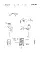
- FIG. 1is a simplified block diagram of a telephone company network, a cellular telephone network and a customer premises installation implementing the concepts of the present invention.
- FIG. 2is a functional block diagram of a smart network interface device (SNID) for use in the customer premises installation illustrated in FIG. 1.
- SNIDsmart network interface device
- FIG. 1provides a simplified representation of a communication system in accord with the present invention.
- An end office switch 11, of the local telephone networkconnects through telephone line loop circuitry to subscriber premises.
- the end office switch 11may be a 1AESS or 5ESS switching system sold by American Telephone and Motorola.
- the loop circuitrymay include a variety of technologies, such as subscriber line carrier (SLC) systems, to combine traffic for a number of lines for longer runs between the subscriber premises and the end office switch 11.
- SLCsubscriber line carrier
- the end office switch 11connects to a number of telephone stations 13 in the normal manner.
- FIG. 1also shows a customer premises 15 having the primary and backup services contemplated by the present invention.
- a wired telephone line 17, typically including a twisted wire drop to the subscriber premises 15,connects from the end office switch 11 to a smart network interface device (SNID) 19.
- the SNID 19is mounted on the outside of the house at the subscriber premises and provides a normal connection from the drop cable of loop 17 to twisted wire pair type subscriber premises wiring 21.
- the subscriber premises wiring 21in turn connects to customer premises equipment, shown as telephone stations 23.
- the SNIDis the demarcation point between the public network elements and the subscriber premises wiring.
- the SNID 19includes interface and transceiver circuitry (as discussed later) to provide wireless telephone communication, as a backup to the normal landline telephone communications.
- FIG. 1shows an antenna 25 connected to the SNID 19 for sending and receiving telephone communication signals via appropriate channels of the wireless telephone network.
- any wireless telephone networkmay be used to carry the backup service communications.
- the wireless telephone networkis a cellular telephone network.
- FIG. 1therefore shows a mobile telephone switching office (MTSO) 27 and one of the base station transceivers 29, of the cellular network servicing the area around the subscriber premises 15.
- MTSOmobile telephone switching office
- the MTSO 27connects to one or more of the switching offices of the local landline telephone network, such as the end office 11, via appropriate line or trunk circuits.
- a number of telephone linesconnect the MTSO to each base station 29.
- the base station 29provides two-way signal conversion between the signal formats on the wireless channels carrying the telephone communications within the particular cell and the signal formats on the lines to the MTSO 27.
- the MTSO 27also conducts wireless signaling with cellular telephones through the base station 29, to set-up and tear down cellular telephone call sessions, to register roaming subscribers' cellular stations, etc.
- the MTSO 27 and the base station 29provide cellular telephone service to mobile and portable cellular telephone units, schematically represented by cellular handset 31, in the normal manner.
- the SNID 19will register with the MTSO 27 as a roaming cellular station, and the MTSO 27 and the base station 29 will provide cellular telephone service through the SNID 19 to the customer premises telephone equipment 23.
- the central processing unit of the MTSO 27also connects to a multi-services platform (MSP) 33 via an appropriate data link.
- MSPmulti-services platform
- the data linkmight provide a 9600 baud data channel over a line to the MSP platform 33.
- the MSP 33provides an interface to the end office switch 11 permitting external programming of certain functions of the switch 11.
- the MTSO 27will activate a call forwarding feature when the SNID 19 registers as active with the MTSO 27.
- the MSP 33connects to the end office switching system 11 via a recent change-memory administration channel (RC-MAC).
- RC-MACis a data link to the processor of the switching system 11 for inputting data into the translation tables used by the end office switching system 11 to control switched communications operations with regard to each subscriber's line.
- the MSP 33is a processor for receiving various service change instructions, including those from the CPU of the MTSO 27 and from other sources.
- the MSP 33processes the instructions as necessary to make them compatible with switch programming and forwards the processed instructions to the switching system 11 to change specific relevant translation table data stored in the memory of the switching system.
- the MTSO 27has a number of directory numbers reserved for use by roaming subscribers. These numbers are referred to as ⁇ temporary directory numbers ⁇ .
- the MTSOassigns one temporary directory number to each roaming subscriber's cellular telephone, as part of the registration procedure when the roamer's telephone enters the area serviced by the MTSO 27.
- the cellular transceiver in the SNID 19has a unit identification, and the MTSO 27 recognizes the SNID transceiver as a valid unit having service through the MTSO 27.
- the cellular systemdoes not assign a normal cellular telephone number to the SNID 19, for regular full time cellular service. Instead, the MTSO 27 treats the SNID 19 as a roaming subscriber.
- the MTSO 27therefore assigns one of the temporary directory numbers to the SNID 19 when the cellular transceiver in the SNID 19 becomes active after interruption of landline telephone service through loop 17.
- the CPU of the MTSO 27supplies a data message to the MSP 33 identifying the SNID 19 (e.g. by landline telephone number or by the transceiver identification).
- the messageincludes the assigned temporary directory number.
- the MSPidentifies the loop 17 from the identification of the SNID and compiles a call forwarding instruction in appropriate format for loading into the profile data associated with the loop 17 in the memory of the end office switching system 11.
- the MSP 33forwards that instruction over an RC-MAC channel to the processor of the end office switch 11.
- the processor of the switching system 11activates call forwarding with respect to the loop 17 and loads the temporary directory number into the appropriate memory location.
- the end office switch 11forwards calls for the telephone number assigned to loop 17 using the assigned temporary directory number.
- the switch 11routes each such call to the MTSO 27, in such a manner that the MTSO can identify the temporary directory number.
- MTSO 27 and base station 29provide cellular routing of the call to the SNID 19 and the customer premises equipment 23.
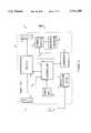
- FIG. 2illustrates the structure of a SNID 19, of the type used in the present invention.
- the SNID 19includes two RJ11 jacks 41, 43.
- the end of the drop cable of telephone line 17terminates in an RJ11 plug (not separately shown). Insertion of the plug on line 17 into the RJ11 jack 41 provides the physical and electrical connection of the SNID 19 to the telephone line.
- An end of the customer premises telephone wiring 21terminates in an RJ11 plug (not separately shown). Insertion of the plug on the wiring 21 into the RJ11 jack 43 provides the physical and electrical connection of the SNID 19 to the customer premises wiring.
- a two position switch 45selectively connects the active pair of wires from the RJ11 jack 43 to either: (1) the active pair of wires of the RJ11 jack 41 or (2) a two-wire line port of a wireless-to-landline interface.
- the switch 45will remain in each state or position until triggered to change to the other position.
- the switch 45connects the active twisted wire pair of the customer premises wiring 21 from RJ11 jack 43 through to the active pair of wires of RJ11 jack 41, and through RJ11 jack 41, to the drop cable of the telephone line 17.
- the switch 45connects the active twisted wire pair of the customer premises wiring 21 from RJ11 jack 43 to the two-wire line port of the wireless-to-landline interface.
- the wireless-to-landline interfaceprovides two-way wireless communication, for wireline equipment connected thereto.
- the wireless-to-landline interfacecomprises a landline-to-cellular interface 49 and a cellular transceiver 51.
- the switch 45connects the active twisted wire pair of the customer premises wiring 21 from RJ11 jack 43 to the two-wire line port of the landline-to-cellular interface 49.
- the switch 45changes between two latched states in response to one or more control signals from a controller 47.
- the switchchanges from the normal line-connected state (1) to the second state (2) connecting the interface 49 in response to a control signal from the controller 47 triggered by a line fault detection, discussed more below.
- the controller 47resets the switch 45 from the second state (2) to the normal line-connected state (1), in response to a manual reset input by a repair technician.
- the switch 45disconnects the line 17 and connects the active twisted wire pair of the customer premises wiring 21 to the landline-to-cellular interface 49.
- the landline-to-cellular interface 49in turn couples the customer premises wiring, connected through the RJ11 jack 43 and the switch 45, to the cellular transceiver 51.
- the landline-to-cellular interface 49presents a two-wire telephone appearance to the switch 45 and through the switch and the RJ11 jack 43 to the customer premises wiring 21. Through this two-wire port connection, the interface 49 emulates a POTS type analog telephone loop from an end office type telephone switching system.
- the interface 49provides line voltage, dial-tone, off-hook detection, digit collection and processing, ringing signal generation, etc., over the two-wire connection to the customer premises wiring 21.
- connection through switch 45 to the interface 49electrically appears virtually the same as the connection through the switch 45 to the drop cable of the telephone line 17.
- the landline-to-cellular interface 49provides all necessary protocol and/or signal format conversions between the signals on the two-wire line side and the signals going to and from the cellular transceiver 51.
- the interface 49will detect dial pulse or DTMF digits representing a telephone number dialed in on one of the stations 23, recognize the end of digit input, and then supply the number as a digit string followed by a ⁇ SEND ⁇ command over the appropriate input connection to the cellular transceiver 51.
- Such an inputcauses the transceiver to initiate an outgoing call through a base station transceiver 29, the MTSO 27 and one or more switches 11 of the PSTN.
- U.S. Pat. No. 4,658,096 to West, Jr. et al.discloses an early example of the landline-to-cellular interface 49.
- the cellular transceiver 51is a standard cellular transceiver unit, without the normally associated control head or handset.
- the interface 49connects to the transceiver 51 in place of the control head or handset.
- the cellular transceiver 51operates in compliance with the communication protocols used by the base station and MTSO of the cellular system serving the particular subscriber. For example, if the cellular system is an AMPS system, then the cellular transceiver 51 is an AMPS compliant transceiver.
- AMPSAMPS compliant transceiver.
- the cellular transceiver 51When activate, the cellular transceiver 51 sends and receives voice frequency information modulated in the relevant cellular telephone RF frequency range via the antenna 25 and the cellular telephone network.
- the interface 49 and cellular transceiver 51thus provide two-way telephone communications for customer premises telephone equipment coupled to wiring 21, as discussed in more detail below.
- the controller 47may take the form of a hard-wired logic circuit. Alternatively, the controller 47 may comprise a programmed microprocessor with associated read only memory (RAM) and random access memory (ROM).
- RAMread only memory
- ROMrandom access memory
- the SNID 19also includes a line fault detector 53, coupled to sense the condition of the telephone line 17 connected to the SNID 19 through the RJ11 jack 41.
- a line fault detector 53coupled to sense the condition of the telephone line 17 connected to the SNID 19 through the RJ11 jack 41.
- a variety of telephone line fault detector circuitsare known (see e.g. above cited Dop et al. Patents). Typically, such a circuit senses the voltage and/or current on the line. For example, a loss of line voltage might indicate either a cut line 17 or a failure of the end office switching system 11.
- the line fault detector 53provides a fault indication to the controller 47 to activate the switch 45, the interface 49 and the cellular transceiver 51.
- the active elements of the SNID 19normally receive power from a power supply circuit 55.
- the power supply 55draws power from the AC mains of the customer premises via an AC plug 57.
- the power supply 55could include a trickle charge circuit and draw operating power from the telephone line 17.
- the SNID 19includes or connects to a back-up battery 59 which provides power to the active elements of the SNID when power supply 55 does not receive power from the AC mains via the plug 57, e.g. due to a power failure.
- a battery charger 61maintains the charge on the back-up battery 59.
- the SNID 19 of the present inventionserves as the demarcation point between the public network(s) and the customer premises wiring.
- the SNID 19normally is installed in some location where it is relatively convenient for telephone company technicians to access the SNID.
- the SNID 19normally is installed on an exterior wall of the dwelling.
- the SNID 19therefore includes a protective housing 63 enclosing all of the connections and electronic components of the SNID.
- the switch 45normally connects the customer premises wiring 21 to the drop cable of the telephone line 17. Persons in the customer premises make and receive telephone calls, using the customer premises telephone equipment 23, via the line 17 and the end office switching system 11 in the normal manner. Assume now that a fault occurs, for example the drop cable portion of the line 17 is accidentally cut.
- the fault detector 53recognizes the loss of line voltage, caused for example by a cut line, as a line fault. In response, the detector 53 provides a fault indication signal to the controller 47. The controller activates the switch 45, the interface 49 and the cellular transceiver 51 in response to the line fault indication from detector 49. The switch 45 disconnects the customer premises wiring 21 from the RJ11 jack 41 and the line 17 and connects the customer premises wiring 21 to the twisted wire pair port of the landline-to-cellular interface 49. The interface 49 begins its operations, e.g. monitoring the customer premises wiring 21 for off-hook and dialing for an outgoing call.
- the cellular transceiver 51executes a normal routine to register as an active unit with the cellular system serving the transceiver's current location. Because the SNID 19 actually is a fixed position installation, the cellular transceiver 51 will execute its registration procedure through standard signaling communications with one local base station 29 and the MTSO 27. As noted above, the MTSO 27 considers the transceiver 49 as a valid cellular unit, albeit of a roaming subscriber.
- the MTSO 27assigns one of its temporary directory numbers to the transceiver 51 in the SNID 19.
- the CPU of the MTSO 27supplies a data message containing the assigned temporary directory number and an identification of the SNID 19 (e.g. by landline telephone number or by the transceiver identification) to the MSP 33.
- the MSP 33identifies the loop 17 from the identification of the SNID contained in the message and compiles a call forwarding instruction in appropriate format for loading into the profile data associated with the loop 17 in the memory of the end office switching system 11.
- the MSP 33forwards that instruction over an RC-MAC channel to the processor of the end office switch 11.
- the processor of the switching system 11activates call forwarding with respect to the loop 17 and loads the temporary number into the appropriate memory location.
- the cellular transceiver 51provides standard two-way cellular telephone call services through the cellular network, and the interface 49 and the switch 45 make those services available to persons at the premises 15 via the customer premises equipment 23. Persons at the customer premises 15 can make and receive calls from the equipment 23 in the normal manner, but such calls now go through the interface 49, the cellular transceiver 51 and the cellular network.
- the end office switch 11forwards calls for the telephone number assigned to loop 17 via the cellular system using the assigned temporary directory number.
- the telephone callgoes through one or more switches of the PSTN, for example through end office switching system 11, to the destination station identified by the dialed digits, e.g. to telephone station 13 shown in FIG. 1.
- the cellular transceiver 51communicates via wireless transmission and reception through antenna 25 with the transceiver in base station 29.
- voice frequency signals from the off-hook station 23go through the wiring 21 and the interface 49 to the outgoing analog audio input of the transceiver 51.
- the transceiver 51in turn modulates the outgoing voice frequency information using the assigned frequency and appropriate modulation techniques utilized on the particular cellular network and applies the modulated RF signal to the antenna 25.
- the antennaradiates the modulated signal for wireless transmission to the antenna associated with base station 29. That antenna supplies the relevant frequency channel to a transceiver in the base station 29 for demodulation.
- the demodulated signalis properly formatted and transmitted over a telephone line or trunk circuit to the MTSO 27.
- the MTSOroutes the signal through the end office switching system 11 to the other party's telephone station 13, and the station 13 provides an audio output thereof to the other party.
- the station 13supplies the audio information through the telephone line to the end office switching system 11.
- the end office switching system 11forwards the audio information to the MTSO 27, and the MTSO forwards that information over the line or trunk circuit to the transceiver in base station 29 that is serving the present call.
- the transceiver in base station 29modulates and broadcasts the audio information using the appropriate modulation technique and the assigned frequency.
- the antenna 25receives the broadcast signal and supplies that signal to the cellular transceiver 51.
- the cellular transceiver 51demodulates the received RF signal to recapture the voice frequency information from the assigned cellular channel.
- the transceiver 51supplies the voice frequency information to the landline-to-cellular interface 49.
- the interface 49supplies the incoming audio signal, at a level compatible with a standard telephone, through the switch 45 and the RJ11 jack 43 to the customer premises wiring 21.
- the off-hook station 23 connected to wiring 21provides an audio output to the calling party at the premises 15, in the normal manner.
- the end office switching system 11forwards the incoming call to the MTSO 27. As part of the forwarding, the end office switching system 11 indicates to the MTSO 27 that the call is for the temporary directory number, i.e. as currently assigned to the transceiver 51.
- the cellular transceiver 51processes cellular call related signaling messages exactly as does a standard cellular telephone.
- the cellular transceiver 51monitors paging or signaling messages on the cellular wireless communications and responds to an addressed paging signal from the MTSO 27 and base station 29 representing the presence of the incoming call.
- the cellular transceiver 51interacts with the base station 29 and the MTSO 27 to receive the incoming call.
- the cellular transceiver 51will provide an appropriate signal indicating the presence of the incoming call to the landline-to-cellular interface 49.
- the interface 49applies a ringing voltage to the two-wire connection.
- the ringing voltagegoes through the switch 45, the RJ11 jack 43 and the customer premises wiring 21 to the customer premises telephone equipment 23. In response, one or more telephones at the premises 15 ring.
- a ring-trip detector in the landline-to-cellular interface 49senses this state transition and terminates the ringing voltage.
- the interface 49signals the answer condition to the cellular transceiver 51 and provides a two-way voice grade analog circuit between the two-wire connection to the telephone station 23 and the voice frequency processing circuitry of the cellular transceiver 51.
- the cellular transceiver 51then provides an answer message to the cellular network, and two-way voice communication commences on the assigned frequency channels in substantially the same manner discussed above relative to the outgoing call example.
- the telephone companywill dispatch a repair crew to repair the cut drop cable portion of the telephone line 17.
- one of the repair technicianswill open the housing 63 and manually activate a reset switch 65 connected to the controller 47.
- the controller 47deactivates the cellular transceiver 51 and the landline interface 49.
- the controller 47also resets the switch 45 to the normal operating position (1). In that position, the switch 45 connects the customer premises wiring 21 through to the drop cable of the telephone line 17.
- the technicianwill also communicate with the switching system 11, using normal maintenance procedures, to cancel call forwarding with respect to the telephone number assigned to the line 17 and the customer premises 15. Persons at the premises 15 can make and receive telephone calls via the line 17 in the normal manner.
- the MTSO 27recognizes that the transceiver is no longer active and lists the temporary directory number as available for reassignment.
Landscapes
- Engineering & Computer Science (AREA)
- Signal Processing (AREA)
- Computer Networks & Wireless Communication (AREA)
- Sub-Exchange Stations And Push- Button Telephones (AREA)
- Mobile Radio Communication Systems (AREA)
Abstract
Description
Claims (21)
Priority Applications (1)
| Application Number | Priority Date | Filing Date | Title |
|---|---|---|---|
| US08/557,396US5751789A (en) | 1995-11-13 | 1995-11-13 | SNID with wireless backup |
Applications Claiming Priority (1)
| Application Number | Priority Date | Filing Date | Title |
|---|---|---|---|
| US08/557,396US5751789A (en) | 1995-11-13 | 1995-11-13 | SNID with wireless backup |
Publications (1)
| Publication Number | Publication Date |
|---|---|
| US5751789Atrue US5751789A (en) | 1998-05-12 |
Family
ID=24225219
Family Applications (1)
| Application Number | Title | Priority Date | Filing Date |
|---|---|---|---|
| US08/557,396Expired - LifetimeUS5751789A (en) | 1995-11-13 | 1995-11-13 | SNID with wireless backup |
Country Status (1)
| Country | Link |
|---|---|
| US (1) | US5751789A (en) |
Cited By (83)
| Publication number | Priority date | Publication date | Assignee | Title |
|---|---|---|---|---|
| US5911123A (en)* | 1996-07-31 | 1999-06-08 | Siemens Information And Communications Networks, Inc. | System and method for providing wireless connections for single-premises digital telephones |
| US5982854A (en)* | 1996-02-23 | 1999-11-09 | Alcatel Usa, Inc. | Fiber optic based subscriber terminal |
| EP0969648A1 (en)* | 1998-06-30 | 2000-01-05 | Siemens Aktiengesellschaft | Methode and system to secure a telecommunication link |
| US6023617A (en)* | 1996-10-09 | 2000-02-08 | Alcatel Usa Sourcing, L.P. | Call routing in a wireless telecommunications system |
| US6081716A (en)* | 1995-05-04 | 2000-06-27 | Interwave Communications, Inc. | Wireless private branch exchange |
| US6088328A (en)* | 1998-12-29 | 2000-07-11 | Nortel Networks Corporation | System and method for restoring failed communication services |
| US6097817A (en)* | 1997-12-10 | 2000-08-01 | Omnipoint Corporation | Encryption and decryption in communication system with wireless trunk |
| US6115604A (en)* | 1998-02-10 | 2000-09-05 | Siemens Information And Communication Networks, Inc. | Method and apparatus for connecting wireless transmissions to analog phone lines |
| US6212375B1 (en)* | 1997-05-15 | 2001-04-03 | Nokia Mobile Phones Limited | Method and apparatus providing residential base carrier inactivation after line failure or line in use |
| WO2001097496A1 (en)* | 2000-06-14 | 2001-12-20 | Mci Worldcom, Inc. | Test unit for use at a network interface device |
| US6353747B1 (en)* | 1997-12-02 | 2002-03-05 | Nec Corporation | Portable cellular phone base station |
| US20020034220A1 (en)* | 2000-09-21 | 2002-03-21 | Tom Duxbury | Apparatus and method for digital subscriber line signal communications |
| US6411802B1 (en) | 1999-03-15 | 2002-06-25 | Bellsouth Intellectual Property Management Corporation | Wireless backup telephone device |
| AU751347B2 (en)* | 1998-01-15 | 2002-08-15 | Interwave Communications International, Ltd. | Wireless private branch exchange |
| US20020155836A1 (en)* | 1998-09-11 | 2002-10-24 | Ameritech Corporation | System and method for providing telecommunications service using a wireless link |
| US6519323B1 (en) | 1999-05-20 | 2003-02-11 | Worldcom, Inc. | Test unit for use at a network interface device |
| US6535480B1 (en)* | 1998-11-20 | 2003-03-18 | At&T Corp. | System and method to provide survivability for broadcast video and interactive IP-based services on cable access networks |
| US6580906B2 (en) | 1997-12-10 | 2003-06-17 | Intel Corporation | Authentication and security in wireless communication system |
| US6591114B1 (en) | 2000-02-24 | 2003-07-08 | Qualicom Systems, Inc. | Fixed cellular communications system |
| US6628947B1 (en)* | 1999-12-09 | 2003-09-30 | Bellsouth Intellectual Property Corporation | Integrated wireless/wireline registration |
| US20030190018A1 (en)* | 2002-04-03 | 2003-10-09 | Bleile Leonard George | Apparatus, method, media and signals for controlling a wireless communication appliance |
| US6661893B1 (en)* | 1999-08-18 | 2003-12-09 | Kenneth Vaughn | Telephone loop monitoring and isolation system |
| US6671883B1 (en)* | 1999-12-15 | 2003-12-30 | At&T Corp. | Method and apparatus for lost connectivity recovery |
| US6714534B1 (en)* | 1997-12-31 | 2004-03-30 | At&T Corp. | Lifeline service for HFCLA network using wireless ISD |
| US20040121726A1 (en)* | 2002-12-18 | 2004-06-24 | Bifano Louis D. | Telecommunications network employing a wireless backup path |
| US20040124976A1 (en)* | 2002-09-12 | 2004-07-01 | Nambi Seshadri | Detecting communications disconnect and enabling wireless emergency call |
| US6775522B2 (en)* | 1994-09-20 | 2004-08-10 | Telular Corporation | Concurrent wireless/landline interface apparatus and method |
| US6775551B1 (en) | 1999-12-30 | 2004-08-10 | Bellsouth Intellectual Property Corporation | Method and apparatus for fixing the location of a fixed wireless terminal in a wireless network |
| US6775552B2 (en) | 1999-12-30 | 2004-08-10 | Bellsouth Intellectual Property Corporation | Method and apparatus for fixing the location of a fixed wireless terminal in a wireless network |
| US6795552B1 (en) | 1999-12-14 | 2004-09-21 | Corning Cable Systems Llc | Enhanced services network interface device |
| US20040208294A1 (en)* | 2003-04-21 | 2004-10-21 | Charlie Sawyer | Communications devices including test circuits and related circuits and methods |
| US20040221213A1 (en)* | 2003-04-21 | 2004-11-04 | Charlie Sawyer | Communications jacks including test circuits and related circuits and methods |
| US20040235483A1 (en)* | 2003-05-21 | 2004-11-25 | Nortel Networks Limited | Call transfer for an integrated wireline and wireless service using a temporary directory number |
| US20040266425A1 (en)* | 2003-06-24 | 2004-12-30 | Sbc, Inc. | Wireless wide area network charger and cradle |
| US20050005001A1 (en)* | 2003-03-28 | 2005-01-06 | Hitachi, Ltd. | Cluster computing system and its failover method |
| US20050003821A1 (en)* | 2003-05-21 | 2005-01-06 | Nortel Networks Limited | Call transfer for an integrated wireline and wireless service |
| US20050054335A1 (en)* | 2003-09-04 | 2005-03-10 | Sbc Knowledge Ventures, L.P. | Call forwarding control device and method of call management |
| US20050063528A1 (en)* | 2003-09-23 | 2005-03-24 | Sbc Knowledge Ventures, L.P. | Location based call routing for call answering services |
| US20050096024A1 (en)* | 2003-11-05 | 2005-05-05 | Sbc Knowledge Ventures, L.P. | System and method of transitioning between cellular and voice over internet protocol communication |
| US6898276B1 (en) | 2002-05-31 | 2005-05-24 | Verizon Communications Inc. | Soft network interface device for digital broadband local carrier networks |
| US20050130646A1 (en)* | 2001-12-26 | 2005-06-16 | Bellsouth Intellectual Property Corporation | Auto sensing home base station for mobile telephone with remote answering capabilities |
| US6961335B1 (en) | 2002-05-31 | 2005-11-01 | Verizon Communications Inc. | Multi-layer ring architecture for fiber-to-the-home telco carrier network |
| US20060003806A1 (en)* | 2004-07-02 | 2006-01-05 | Sbc Knowledge Ventures, L.P. | Phone synchronization device and method of handling personal information |
| US7149514B1 (en) | 1997-07-30 | 2006-12-12 | Bellsouth Intellectual Property Corp. | Cellular docking station |
| US7151943B2 (en) | 1999-09-20 | 2006-12-19 | Cellemetry, Llc | System for communicating messages via a forward overhead control channel for a programmable logic control device |
| US7194243B2 (en) | 2004-04-02 | 2007-03-20 | Maryland Semiconductor Inc. | DC offset and 1/f noise compensation of a direct conversion receiver |
| US7194083B1 (en) | 2002-07-15 | 2007-03-20 | Bellsouth Intellectual Property Corporation | System and method for interfacing plain old telephone system (POTS) devices with cellular networks |
| US7233802B2 (en) | 1999-10-29 | 2007-06-19 | Cellemetry, Llc | Interconnect system and method for multiple protocol short message services |
| US7245928B2 (en) | 2000-10-27 | 2007-07-17 | Cellemetry, Llc | Method and system for improved short message services |
| US7272494B2 (en) | 2002-03-28 | 2007-09-18 | Numerex Investment Corp. | Communications device for conveying geographic location information over capacity constrained wireless systems |
| USRE39989E1 (en)* | 1989-10-31 | 2008-01-01 | Morris Walker C | Method and apparatus for transmission of analog and digital |
| US7323970B1 (en) | 2004-01-21 | 2008-01-29 | Numerex Corporation | Method and system for remote interaction with a vehicle via wireless communication |
| US20080056224A1 (en)* | 2006-08-31 | 2008-03-06 | Hoiness Stuart E | Network interface wireless router |
| US20080192769A1 (en)* | 1997-07-30 | 2008-08-14 | Steven Tischer | Apparatus and method for prioritizing communications between devices |
| US20080194251A1 (en)* | 1997-07-30 | 2008-08-14 | Steven Tischer | Apparatus and method for providing communications and connection-oriented services to devices |
| US7508754B1 (en)* | 2004-02-27 | 2009-03-24 | Sprint Spectrum L.P. | Method and system to support internal calling upon loss of connection with IP Centrex server |
| US20100017583A1 (en)* | 2008-07-15 | 2010-01-21 | International Business Machines Corporation | Call Stack Sampling for a Multi-Processor System |
| US7680471B2 (en) | 2006-05-17 | 2010-03-16 | Numerex Corp. | System and method for prolonging wireless data product's life |
| US7783508B2 (en) | 1999-09-20 | 2010-08-24 | Numerex Corp. | Method and system for refining vending operations based on wireless data |
| US20110019806A1 (en)* | 2008-05-07 | 2011-01-27 | Huawei Device Co., Ltd. | Method and system for switching voice service between different networks, and customer premises equipment |
| US7983670B1 (en)* | 2004-03-18 | 2011-07-19 | Verizon Corporate Services Group Inc. | Wireless fallback for subscribers of wirelined networks |
| US8000682B2 (en) | 2002-07-15 | 2011-08-16 | At&T Intellectual Property I, L.P. | Apparatus and method for restricting access to data |
| US8243908B2 (en) | 2002-07-15 | 2012-08-14 | At&T Intellectual Property I, Lp | Systems and methods for restricting the use and movement of telephony devices |
| US8249570B2 (en) | 1997-07-30 | 2012-08-21 | At&T Intellectual Property I, L.P. | Apparatus, method, and computer-readable medium for interfacing devices with communications networks |
| US8265605B2 (en) | 2007-02-06 | 2012-09-11 | Numerex Corp. | Service escrowed transportable wireless event reporting system |
| US8271024B1 (en) | 2003-11-26 | 2012-09-18 | Genband Us Llc | Messaging service interworking |
| US8275371B2 (en) | 2002-07-15 | 2012-09-25 | At&T Intellectual Property I, L.P. | Apparatus and method for providing communications and connection-oriented services to devices |
| US8285292B1 (en)* | 2000-02-11 | 2012-10-09 | At&T Mobility Ii Llc | Detection of cross-connection between a wireless loop network and another loop network at a subscriber's premises |
| CN1758621B (en)* | 1999-10-22 | 2012-12-05 | 耐克斯特奈特无线公司 | Automatic computerized house equipment register in wireless communication system |
| US8416804B2 (en) | 2002-07-15 | 2013-04-09 | At&T Intellectual Property I, L.P. | Apparatus and method for providing a user interface for facilitating communications between devices |
| US8526466B2 (en) | 2002-07-15 | 2013-09-03 | At&T Intellectual Property I, L.P. | Apparatus and method for prioritizing communications between devices |
| US8543098B2 (en) | 2002-07-15 | 2013-09-24 | At&T Intellectual Property I, L.P. | Apparatus and method for securely providing communications between devices and networks |
| US8554187B2 (en) | 2002-07-15 | 2013-10-08 | At&T Intellectual Property I, L.P. | Apparatus and method for routing communications between networks and devices |
| US8799904B2 (en) | 2011-01-21 | 2014-08-05 | International Business Machines Corporation | Scalable system call stack sampling |
| US8799872B2 (en) | 2010-06-27 | 2014-08-05 | International Business Machines Corporation | Sampling with sample pacing |
| US8843684B2 (en) | 2010-06-11 | 2014-09-23 | International Business Machines Corporation | Performing call stack sampling by setting affinity of target thread to a current process to prevent target thread migration |
| US20150110098A1 (en)* | 2012-12-31 | 2015-04-23 | Huawei Device Co., Ltd. | Data Transmission Method, Device, and Gateway |
| US9094152B2 (en) | 2012-11-07 | 2015-07-28 | Verizon Patent And Licensing Inc. | Rerouting T1 signal over a wide area network |
| US9176783B2 (en) | 2010-05-24 | 2015-11-03 | International Business Machines Corporation | Idle transitions sampling with execution context |
| US9418005B2 (en) | 2008-07-15 | 2016-08-16 | International Business Machines Corporation | Managing garbage collection in a data processing system |
| US9544739B2 (en) | 2013-12-06 | 2017-01-10 | Cellco Partnership | Enhanced 911 for fixed wireless |
| US10530479B2 (en) | 2012-03-02 | 2020-01-07 | Corning Optical Communications LLC | Systems with optical network units (ONUs) for high bandwidth connectivity, and related components and methods |
| US10735838B2 (en) | 2016-11-14 | 2020-08-04 | Corning Optical Communications LLC | Transparent wireless bridges for optical fiber-wireless networks and related methods and systems |
Citations (29)
| Publication number | Priority date | Publication date | Assignee | Title |
|---|---|---|---|---|
| US4456793A (en)* | 1982-06-09 | 1984-06-26 | Bell Telephone Laboratories, Incorporated | Cordless telephone system |
| US4542262A (en)* | 1980-11-12 | 1985-09-17 | Licentia Patent-Verwaltungs-Gmbh | Subscriber telephone station |
| US4628152A (en)* | 1981-12-21 | 1986-12-09 | Telefonaktiebolaget Lm Ericsson | Method and apparatus for transmission of telephone calls to a portable, wireless telephone set |
| US4658096A (en)* | 1984-09-18 | 1987-04-14 | Metrofone, Inc. | System for interfacing a standard telephone set with a radio transceiver |
| US4682351A (en)* | 1984-10-29 | 1987-07-21 | Nec Corporation | Cordless Telephone system |
| US4731812A (en)* | 1985-05-09 | 1988-03-15 | Telefonaktiebolaget Lm Ericsson | Installation with portable, wireless telephone sets |
| US4754473A (en)* | 1986-10-16 | 1988-06-28 | Willie Edwards | Remote telephonic data transcribing system |
| US4776000A (en)* | 1986-01-28 | 1988-10-04 | Raoul Parienti | Telephone communications system with portable handsets |
| US4825457A (en)* | 1988-04-25 | 1989-04-25 | Lebowitz Mayer M | Cellular network data transmission system |
| US4868859A (en)* | 1987-06-12 | 1989-09-19 | Bt Telecom, Inc. | Supervised, interactive alarm reporting system |
| US4878238A (en)* | 1987-12-23 | 1989-10-31 | Rash Mark S | Cordless telephone network |
| US4887290A (en)* | 1987-08-05 | 1989-12-12 | Norbert W. Zawacki | Cellular alarm backup system |
| US4993059A (en)* | 1989-02-08 | 1991-02-12 | Cableguard, Inc. | Alarm system utilizing wireless communication path |
| US5012511A (en)* | 1990-04-06 | 1991-04-30 | Bell Atlantic Network Services, Inc. | Method of and system for control of special services by remote access |
| US5020094A (en)* | 1987-12-23 | 1991-05-28 | Rash Mark S | Cordless telephone network |
| US5027383A (en)* | 1987-06-12 | 1991-06-25 | Versus Technology, Inc. | Supervised, interactive alarm reporting system |
| US5068890A (en)* | 1986-10-22 | 1991-11-26 | Nilssen Ole K | Combined signal and electrical power distribution system |
| US5138651A (en)* | 1989-02-23 | 1992-08-11 | Fujitsu Limited | Cordless loud speaking telephone |
| US5146486A (en)* | 1989-08-31 | 1992-09-08 | Lebowitz Mayer M | Cellular network data transmission system |
| US5185779A (en)* | 1987-08-05 | 1993-02-09 | Norbert Zawacki | Cellular alarm backup system |
| US5210788A (en)* | 1986-10-22 | 1993-05-11 | Nilssen Ole K | Telephone instrument and distribution system |
| US5235638A (en)* | 1991-09-12 | 1993-08-10 | Bell Atlantic Network Services, Inc. | Telephone network interface |
| US5241410A (en)* | 1990-06-21 | 1993-08-31 | Litephone Systems Ltd. | Enhanced infrared-connected telephone system |
| US5247701A (en)* | 1990-06-29 | 1993-09-21 | Motorola, Inc. | On-site/trunking system frequency sharing |
| US5255308A (en)* | 1990-02-08 | 1993-10-19 | Nec Corporation | Wide area cordless telephone system capable of receiving incoming group address calls |
| US5259017A (en)* | 1989-04-04 | 1993-11-02 | Siemens Aktiengesellschaft | Cordless telephone system with a private automatic branch exchange |
| US5327478A (en)* | 1989-08-31 | 1994-07-05 | Lebowitz Mayer M | Cellular network data transmission system |
| US5353311A (en)* | 1992-01-09 | 1994-10-04 | Nec Corporation | Radio transmitter |
| US5572193A (en)* | 1990-12-07 | 1996-11-05 | Motorola, Inc. | Method for authentication and protection of subscribers in telecommunications systems |
- 1995
- 1995-11-13USUS08/557,396patent/US5751789A/ennot_activeExpired - Lifetime
Patent Citations (29)
| Publication number | Priority date | Publication date | Assignee | Title |
|---|---|---|---|---|
| US4542262A (en)* | 1980-11-12 | 1985-09-17 | Licentia Patent-Verwaltungs-Gmbh | Subscriber telephone station |
| US4628152A (en)* | 1981-12-21 | 1986-12-09 | Telefonaktiebolaget Lm Ericsson | Method and apparatus for transmission of telephone calls to a portable, wireless telephone set |
| US4456793A (en)* | 1982-06-09 | 1984-06-26 | Bell Telephone Laboratories, Incorporated | Cordless telephone system |
| US4658096A (en)* | 1984-09-18 | 1987-04-14 | Metrofone, Inc. | System for interfacing a standard telephone set with a radio transceiver |
| US4682351A (en)* | 1984-10-29 | 1987-07-21 | Nec Corporation | Cordless Telephone system |
| US4731812A (en)* | 1985-05-09 | 1988-03-15 | Telefonaktiebolaget Lm Ericsson | Installation with portable, wireless telephone sets |
| US4776000A (en)* | 1986-01-28 | 1988-10-04 | Raoul Parienti | Telephone communications system with portable handsets |
| US4754473A (en)* | 1986-10-16 | 1988-06-28 | Willie Edwards | Remote telephonic data transcribing system |
| US5210788A (en)* | 1986-10-22 | 1993-05-11 | Nilssen Ole K | Telephone instrument and distribution system |
| US5068890A (en)* | 1986-10-22 | 1991-11-26 | Nilssen Ole K | Combined signal and electrical power distribution system |
| US4868859A (en)* | 1987-06-12 | 1989-09-19 | Bt Telecom, Inc. | Supervised, interactive alarm reporting system |
| US5027383A (en)* | 1987-06-12 | 1991-06-25 | Versus Technology, Inc. | Supervised, interactive alarm reporting system |
| US5185779A (en)* | 1987-08-05 | 1993-02-09 | Norbert Zawacki | Cellular alarm backup system |
| US4887290A (en)* | 1987-08-05 | 1989-12-12 | Norbert W. Zawacki | Cellular alarm backup system |
| US5020094A (en)* | 1987-12-23 | 1991-05-28 | Rash Mark S | Cordless telephone network |
| US4878238A (en)* | 1987-12-23 | 1989-10-31 | Rash Mark S | Cordless telephone network |
| US4825457A (en)* | 1988-04-25 | 1989-04-25 | Lebowitz Mayer M | Cellular network data transmission system |
| US4993059A (en)* | 1989-02-08 | 1991-02-12 | Cableguard, Inc. | Alarm system utilizing wireless communication path |
| US5138651A (en)* | 1989-02-23 | 1992-08-11 | Fujitsu Limited | Cordless loud speaking telephone |
| US5259017A (en)* | 1989-04-04 | 1993-11-02 | Siemens Aktiengesellschaft | Cordless telephone system with a private automatic branch exchange |
| US5146486A (en)* | 1989-08-31 | 1992-09-08 | Lebowitz Mayer M | Cellular network data transmission system |
| US5327478A (en)* | 1989-08-31 | 1994-07-05 | Lebowitz Mayer M | Cellular network data transmission system |
| US5255308A (en)* | 1990-02-08 | 1993-10-19 | Nec Corporation | Wide area cordless telephone system capable of receiving incoming group address calls |
| US5012511A (en)* | 1990-04-06 | 1991-04-30 | Bell Atlantic Network Services, Inc. | Method of and system for control of special services by remote access |
| US5241410A (en)* | 1990-06-21 | 1993-08-31 | Litephone Systems Ltd. | Enhanced infrared-connected telephone system |
| US5247701A (en)* | 1990-06-29 | 1993-09-21 | Motorola, Inc. | On-site/trunking system frequency sharing |
| US5572193A (en)* | 1990-12-07 | 1996-11-05 | Motorola, Inc. | Method for authentication and protection of subscribers in telecommunications systems |
| US5235638A (en)* | 1991-09-12 | 1993-08-10 | Bell Atlantic Network Services, Inc. | Telephone network interface |
| US5353311A (en)* | 1992-01-09 | 1994-10-04 | Nec Corporation | Radio transmitter |
Cited By (139)
| Publication number | Priority date | Publication date | Assignee | Title |
|---|---|---|---|---|
| USRE39989E1 (en)* | 1989-10-31 | 2008-01-01 | Morris Walker C | Method and apparatus for transmission of analog and digital |
| US6785517B2 (en)* | 1994-09-20 | 2004-08-31 | Telular Corp. | Concurrent wireless/landline interface apparatus and method |
| US6775522B2 (en)* | 1994-09-20 | 2004-08-10 | Telular Corporation | Concurrent wireless/landline interface apparatus and method |
| US7089034B1 (en)* | 1994-09-20 | 2006-08-08 | Telular Corp. | Concurrent wireless/landline interface |
| US6081716A (en)* | 1995-05-04 | 2000-06-27 | Interwave Communications, Inc. | Wireless private branch exchange |
| US6246750B1 (en)* | 1996-02-23 | 2001-06-12 | Alcatel Usa, Inc. | Fiber optic based subscriber terminal |
| US5982854A (en)* | 1996-02-23 | 1999-11-09 | Alcatel Usa, Inc. | Fiber optic based subscriber terminal |
| US5911123A (en)* | 1996-07-31 | 1999-06-08 | Siemens Information And Communications Networks, Inc. | System and method for providing wireless connections for single-premises digital telephones |
| US6023617A (en)* | 1996-10-09 | 2000-02-08 | Alcatel Usa Sourcing, L.P. | Call routing in a wireless telecommunications system |
| US6212375B1 (en)* | 1997-05-15 | 2001-04-03 | Nokia Mobile Phones Limited | Method and apparatus providing residential base carrier inactivation after line failure or line in use |
| US20080192769A1 (en)* | 1997-07-30 | 2008-08-14 | Steven Tischer | Apparatus and method for prioritizing communications between devices |
| US8249570B2 (en) | 1997-07-30 | 2012-08-21 | At&T Intellectual Property I, L.P. | Apparatus, method, and computer-readable medium for interfacing devices with communications networks |
| US7363034B2 (en) | 1997-07-30 | 2008-04-22 | At&T Delaware Intellectual Property, Inc. | Cellular docking station |
| US8583106B2 (en) | 1997-07-30 | 2013-11-12 | At&T Intellectual Property I, L.P. | Cellular docking station |
| US20080194251A1 (en)* | 1997-07-30 | 2008-08-14 | Steven Tischer | Apparatus and method for providing communications and connection-oriented services to devices |
| US9258845B2 (en) | 1997-07-30 | 2016-02-09 | At&T Intellectual Property I, L.P. | Cellular docking station |
| US7149514B1 (en) | 1997-07-30 | 2006-12-12 | Bellsouth Intellectual Property Corp. | Cellular docking station |
| US6353747B1 (en)* | 1997-12-02 | 2002-03-05 | Nec Corporation | Portable cellular phone base station |
| US6097817A (en)* | 1997-12-10 | 2000-08-01 | Omnipoint Corporation | Encryption and decryption in communication system with wireless trunk |
| US6580906B2 (en) | 1997-12-10 | 2003-06-17 | Intel Corporation | Authentication and security in wireless communication system |
| US6714534B1 (en)* | 1997-12-31 | 2004-03-30 | At&T Corp. | Lifeline service for HFCLA network using wireless ISD |
| AU751347B2 (en)* | 1998-01-15 | 2002-08-15 | Interwave Communications International, Ltd. | Wireless private branch exchange |
| US6115604A (en)* | 1998-02-10 | 2000-09-05 | Siemens Information And Communication Networks, Inc. | Method and apparatus for connecting wireless transmissions to analog phone lines |
| EP0969648A1 (en)* | 1998-06-30 | 2000-01-05 | Siemens Aktiengesellschaft | Methode and system to secure a telecommunication link |
| US6788942B2 (en)* | 1998-09-11 | 2004-09-07 | Sbc Properties, L.P. | System and method for providing telecommunications service using a wireless link |
| US20040264446A1 (en)* | 1998-09-11 | 2004-12-30 | Sbc Properties, L.P. | System and method for providing telecommunications service using a wireless link |
| US20020155836A1 (en)* | 1998-09-11 | 2002-10-24 | Ameritech Corporation | System and method for providing telecommunications service using a wireless link |
| US7590052B2 (en) | 1998-09-11 | 2009-09-15 | At&T Intellectual Property I, L.P. | System and method for providing telecommunications service using a wireless link |
| US6535480B1 (en)* | 1998-11-20 | 2003-03-18 | At&T Corp. | System and method to provide survivability for broadcast video and interactive IP-based services on cable access networks |
| US6088328A (en)* | 1998-12-29 | 2000-07-11 | Nortel Networks Corporation | System and method for restoring failed communication services |
| US6411802B1 (en) | 1999-03-15 | 2002-06-25 | Bellsouth Intellectual Property Management Corporation | Wireless backup telephone device |
| US6757528B1 (en)* | 1999-03-15 | 2004-06-29 | Bellsouth Intellectual Property Management Corporation | Wireless backup telephone device and associated support system |
| US20040214569A1 (en)* | 1999-03-15 | 2004-10-28 | Cardina Donald M. | Wireless backup telephone device |
| US20070054660A1 (en)* | 1999-03-15 | 2007-03-08 | Bellsouth Intellectual Property Corporation | Wireless Backup Telephone Device |
| US7130609B2 (en) | 1999-03-15 | 2006-10-31 | Bellsouth Intellectual Property Corp. | Wireless backup telephone device and associated support system |
| US6519323B1 (en) | 1999-05-20 | 2003-02-11 | Worldcom, Inc. | Test unit for use at a network interface device |
| US6912269B2 (en) | 1999-05-20 | 2005-06-28 | Mci, Inc. | Test unit for use at a network interface device |
| US20030063713A1 (en)* | 1999-05-20 | 2003-04-03 | Worldcom, Inc. | Test unit for use at a network interface device |
| US6661893B1 (en)* | 1999-08-18 | 2003-12-09 | Kenneth Vaughn | Telephone loop monitoring and isolation system |
| US7151943B2 (en) | 1999-09-20 | 2006-12-19 | Cellemetry, Llc | System for communicating messages via a forward overhead control channel for a programmable logic control device |
| US8484070B2 (en) | 1999-09-20 | 2013-07-09 | Numerex Corp. | Method and system for managing vending operations based on wireless data |
| US8214247B2 (en) | 1999-09-20 | 2012-07-03 | Numerex Corp. | Methods and system for managing vending operations based on wireless data |
| US8126764B2 (en) | 1999-09-20 | 2012-02-28 | Numerex, Corporation | Communication of managing vending operations based on wireless data |
| US7783508B2 (en) | 1999-09-20 | 2010-08-24 | Numerex Corp. | Method and system for refining vending operations based on wireless data |
| CN1758621B (en)* | 1999-10-22 | 2012-12-05 | 耐克斯特奈特无线公司 | Automatic computerized house equipment register in wireless communication system |
| US7233802B2 (en) | 1999-10-29 | 2007-06-19 | Cellemetry, Llc | Interconnect system and method for multiple protocol short message services |
| US7130628B2 (en)* | 1999-12-09 | 2006-10-31 | Bellsouth Intellectual Property Corporation | Integrated wireless/wireline registration |
| US20040005891A1 (en)* | 1999-12-09 | 2004-01-08 | Yu Christopher C. | Integrated wireless/wireline registration |
| US6628947B1 (en)* | 1999-12-09 | 2003-09-30 | Bellsouth Intellectual Property Corporation | Integrated wireless/wireline registration |
| US6795552B1 (en) | 1999-12-14 | 2004-09-21 | Corning Cable Systems Llc | Enhanced services network interface device |
| US6671883B1 (en)* | 1999-12-15 | 2003-12-30 | At&T Corp. | Method and apparatus for lost connectivity recovery |
| USRE40641E1 (en) | 1999-12-30 | 2009-02-17 | Jasper Wireless Llc | Method and apparatus for fixing the location of a fixed wireless terminal in a wireless network |
| US6775551B1 (en) | 1999-12-30 | 2004-08-10 | Bellsouth Intellectual Property Corporation | Method and apparatus for fixing the location of a fixed wireless terminal in a wireless network |
| US6775552B2 (en) | 1999-12-30 | 2004-08-10 | Bellsouth Intellectual Property Corporation | Method and apparatus for fixing the location of a fixed wireless terminal in a wireless network |
| US8285292B1 (en)* | 2000-02-11 | 2012-10-09 | At&T Mobility Ii Llc | Detection of cross-connection between a wireless loop network and another loop network at a subscriber's premises |
| US6591114B1 (en) | 2000-02-24 | 2003-07-08 | Qualicom Systems, Inc. | Fixed cellular communications system |
| WO2001097496A1 (en)* | 2000-06-14 | 2001-12-20 | Mci Worldcom, Inc. | Test unit for use at a network interface device |
| US20020034220A1 (en)* | 2000-09-21 | 2002-03-21 | Tom Duxbury | Apparatus and method for digital subscriber line signal communications |
| US8903437B2 (en) | 2000-10-27 | 2014-12-02 | Numerex Corp. | Method and system for efficiently routing messages |
| US7680505B2 (en) | 2000-10-27 | 2010-03-16 | Cellemetry, Llc | Telemetry gateway |
| US8543146B2 (en) | 2000-10-27 | 2013-09-24 | Cellemetry, Llc | Method and system for efficiently routing messages |
| US8060067B2 (en) | 2000-10-27 | 2011-11-15 | Cellemetry Llc | Method and system for efficiently routing messages |
| US7245928B2 (en) | 2000-10-27 | 2007-07-17 | Cellemetry, Llc | Method and system for improved short message services |
| US7120454B1 (en) | 2001-12-26 | 2006-10-10 | Bellsouth Intellectual Property Corp. | Auto sensing home base station for mobile telephone with remote answering capabilites |
| US8515417B2 (en) | 2001-12-26 | 2013-08-20 | At&T Intellectual Property I, L.P. | Auto sensing home base station for mobile telephone with remote answering capabilities |
| US20050130646A1 (en)* | 2001-12-26 | 2005-06-16 | Bellsouth Intellectual Property Corporation | Auto sensing home base station for mobile telephone with remote answering capabilities |
| US8046007B2 (en) | 2001-12-26 | 2011-10-25 | At&T Intellectual Property I, L.P. | Auto sensing home base station for mobile telephone with remote answering capabilities |
| US7221950B2 (en) | 2001-12-26 | 2007-05-22 | Bellsouth Intellectual Property Corp. | Auto sensing home base station for mobile telephone with remote answering capabilities |
| US7272494B2 (en) | 2002-03-28 | 2007-09-18 | Numerex Investment Corp. | Communications device for conveying geographic location information over capacity constrained wireless systems |
| US20030190018A1 (en)* | 2002-04-03 | 2003-10-09 | Bleile Leonard George | Apparatus, method, media and signals for controlling a wireless communication appliance |
| US7162228B2 (en) | 2002-04-03 | 2007-01-09 | Embedded Systems Products Inc. | Apparatus, method, media and signals for controlling a wireless communication appliance |
| US6961335B1 (en) | 2002-05-31 | 2005-11-01 | Verizon Communications Inc. | Multi-layer ring architecture for fiber-to-the-home telco carrier network |
| US6898276B1 (en) | 2002-05-31 | 2005-05-24 | Verizon Communications Inc. | Soft network interface device for digital broadband local carrier networks |
| US8526466B2 (en) | 2002-07-15 | 2013-09-03 | At&T Intellectual Property I, L.P. | Apparatus and method for prioritizing communications between devices |
| US8543098B2 (en) | 2002-07-15 | 2013-09-24 | At&T Intellectual Property I, L.P. | Apparatus and method for securely providing communications between devices and networks |
| US8554187B2 (en) | 2002-07-15 | 2013-10-08 | At&T Intellectual Property I, L.P. | Apparatus and method for routing communications between networks and devices |
| US8885666B2 (en) | 2002-07-15 | 2014-11-11 | At&T Intellectual Property I, L.P. | Apparatus and method for providing a user interface for facilitating communications between devices |
| US8416804B2 (en) | 2002-07-15 | 2013-04-09 | At&T Intellectual Property I, L.P. | Apparatus and method for providing a user interface for facilitating communications between devices |
| US8275371B2 (en) | 2002-07-15 | 2012-09-25 | At&T Intellectual Property I, L.P. | Apparatus and method for providing communications and connection-oriented services to devices |
| US8243908B2 (en) | 2002-07-15 | 2012-08-14 | At&T Intellectual Property I, Lp | Systems and methods for restricting the use and movement of telephony devices |
| US8000682B2 (en) | 2002-07-15 | 2011-08-16 | At&T Intellectual Property I, L.P. | Apparatus and method for restricting access to data |
| US7194083B1 (en) | 2002-07-15 | 2007-03-20 | Bellsouth Intellectual Property Corporation | System and method for interfacing plain old telephone system (POTS) devices with cellular networks |
| US20040124976A1 (en)* | 2002-09-12 | 2004-07-01 | Nambi Seshadri | Detecting communications disconnect and enabling wireless emergency call |
| US7053768B2 (en)* | 2002-09-12 | 2006-05-30 | Broadcom Corporation | Detecting communications disconnect and enabling wireless emergency call |
| US20040121726A1 (en)* | 2002-12-18 | 2004-06-24 | Bifano Louis D. | Telecommunications network employing a wireless backup path |
| US7356348B2 (en)* | 2002-12-18 | 2008-04-08 | General Instrument Corporation | Method and apparatus for providing telecommunications over a cable network employing a wireless communication path as an alternative backup path |
| US7370099B2 (en)* | 2003-03-28 | 2008-05-06 | Hitachi, Ltd. | Cluster computing system and its failover method |
| US20050005001A1 (en)* | 2003-03-28 | 2005-01-06 | Hitachi, Ltd. | Cluster computing system and its failover method |
| US20040221213A1 (en)* | 2003-04-21 | 2004-11-04 | Charlie Sawyer | Communications jacks including test circuits and related circuits and methods |
| US20040208294A1 (en)* | 2003-04-21 | 2004-10-21 | Charlie Sawyer | Communications devices including test circuits and related circuits and methods |
| US7073108B2 (en)* | 2003-04-21 | 2006-07-04 | Bellsouth Intellectual Property Corporation | Communications jacks including test circuits and related circuits and methods |
| US7298829B2 (en)* | 2003-04-21 | 2007-11-20 | At&T Bls Intellectual Property, Inc. | Communications devices including test circuits and related circuits and methods |
| US20040235483A1 (en)* | 2003-05-21 | 2004-11-25 | Nortel Networks Limited | Call transfer for an integrated wireline and wireless service using a temporary directory number |
| US20050003857A1 (en)* | 2003-05-21 | 2005-01-06 | Nortel Networks Limited | Call transfer for an integrated wireline and wireless service using a temporary directory number |
| US9078174B2 (en) | 2003-05-21 | 2015-07-07 | Rpx Clearinghouse Llc | Call transfer for an integrated wireline and wireless service |
| US7844270B2 (en) | 2003-05-21 | 2010-11-30 | Nortel Networks Limited | Call transfer for an integrated wireline and wireless service using a temporary directory number |
| US20050003821A1 (en)* | 2003-05-21 | 2005-01-06 | Nortel Networks Limited | Call transfer for an integrated wireline and wireless service |
| US20040266425A1 (en)* | 2003-06-24 | 2004-12-30 | Sbc, Inc. | Wireless wide area network charger and cradle |
| US20050054335A1 (en)* | 2003-09-04 | 2005-03-10 | Sbc Knowledge Ventures, L.P. | Call forwarding control device and method of call management |
| US7616950B2 (en)* | 2003-09-04 | 2009-11-10 | At&T Intellectual Property I, L.P. | Call forwarding control device and method of call management |
| US20050063528A1 (en)* | 2003-09-23 | 2005-03-24 | Sbc Knowledge Ventures, L.P. | Location based call routing for call answering services |
| US20050096024A1 (en)* | 2003-11-05 | 2005-05-05 | Sbc Knowledge Ventures, L.P. | System and method of transitioning between cellular and voice over internet protocol communication |
| US20090238147A1 (en)* | 2003-11-05 | 2009-09-24 | At&T Intellectual Property I, L.P. | System and Method of Transitioning Between Cellular and Voice Over Internet Protocol Communication |
| US7577427B2 (en) | 2003-11-05 | 2009-08-18 | At&T Intellectual Property I, L.P. | System and method of transitioning between cellular and voice over internet protocol communication |
| US7885657B2 (en) | 2003-11-05 | 2011-02-08 | At&T Intellectual Property I, L.P. | System and method of transitioning between cellular and voice over internet protocol communication |
| US8271024B1 (en) | 2003-11-26 | 2012-09-18 | Genband Us Llc | Messaging service interworking |
| US7936256B2 (en) | 2004-01-21 | 2011-05-03 | Numerex Corp. | Method and system for interacting with a vehicle over a mobile radiotelephone network |
| US8269618B2 (en) | 2004-01-21 | 2012-09-18 | Numerex Corp. | Method and system for remotely monitoring the location of a vehicle |
| US7880599B2 (en) | 2004-01-21 | 2011-02-01 | Numerex Corp. | Method and system for remotely monitoring the operations of a vehicle |
| US8547212B2 (en) | 2004-01-21 | 2013-10-01 | Numerex Corporation | Method and system for interacting with a vehicle over a mobile radiotelephone network |
| US8253549B2 (en) | 2004-01-21 | 2012-08-28 | Numerex Corp. | Method and system for interacting with a vehicle over a mobile radiotelephone network |
| US9084197B2 (en) | 2004-01-21 | 2015-07-14 | Numerex Corp. | Method and system for interacting with a vehicle over a mobile radiotelephone network |
| US7323970B1 (en) | 2004-01-21 | 2008-01-29 | Numerex Corporation | Method and system for remote interaction with a vehicle via wireless communication |
| US7508754B1 (en)* | 2004-02-27 | 2009-03-24 | Sprint Spectrum L.P. | Method and system to support internal calling upon loss of connection with IP Centrex server |
| US7983670B1 (en)* | 2004-03-18 | 2011-07-19 | Verizon Corporate Services Group Inc. | Wireless fallback for subscribers of wirelined networks |
| US7194243B2 (en) | 2004-04-02 | 2007-03-20 | Maryland Semiconductor Inc. | DC offset and 1/f noise compensation of a direct conversion receiver |
| US20060003806A1 (en)* | 2004-07-02 | 2006-01-05 | Sbc Knowledge Ventures, L.P. | Phone synchronization device and method of handling personal information |
| US8483748B2 (en) | 2006-05-17 | 2013-07-09 | Numerex Corp. | Digital upgrade system and method |
| US8041383B2 (en) | 2006-05-17 | 2011-10-18 | Numerex Corporation | Digital upgrade system and method |
| US8868059B2 (en) | 2006-05-17 | 2014-10-21 | Numerex Corp. | Digital upgrade system and method |
| US7680471B2 (en) | 2006-05-17 | 2010-03-16 | Numerex Corp. | System and method for prolonging wireless data product's life |
| US20080056224A1 (en)* | 2006-08-31 | 2008-03-06 | Hoiness Stuart E | Network interface wireless router |
| US8023997B2 (en) | 2006-08-31 | 2011-09-20 | Corning Cable Systems Llc | Network interface wireless router |
| US8265605B2 (en) | 2007-02-06 | 2012-09-11 | Numerex Corp. | Service escrowed transportable wireless event reporting system |
| US8543097B2 (en) | 2007-02-06 | 2013-09-24 | Numerex Corp. | Service escrowed transportable wireless event reporting system |
| US8855716B2 (en) | 2007-02-06 | 2014-10-07 | Numerex Corp. | Service escrowed transportable wireless event reporting system |
| US20110019806A1 (en)* | 2008-05-07 | 2011-01-27 | Huawei Device Co., Ltd. | Method and system for switching voice service between different networks, and customer premises equipment |
| EP2242234A4 (en)* | 2008-05-07 | 2013-01-16 | Huawei Device Co Ltd | Method, system and customer premises equipment for voice service switching between different networks |
| US9418005B2 (en) | 2008-07-15 | 2016-08-16 | International Business Machines Corporation | Managing garbage collection in a data processing system |
| US20100017583A1 (en)* | 2008-07-15 | 2010-01-21 | International Business Machines Corporation | Call Stack Sampling for a Multi-Processor System |
| US9176783B2 (en) | 2010-05-24 | 2015-11-03 | International Business Machines Corporation | Idle transitions sampling with execution context |
| US8843684B2 (en) | 2010-06-11 | 2014-09-23 | International Business Machines Corporation | Performing call stack sampling by setting affinity of target thread to a current process to prevent target thread migration |
| US8799872B2 (en) | 2010-06-27 | 2014-08-05 | International Business Machines Corporation | Sampling with sample pacing |
| US8799904B2 (en) | 2011-01-21 | 2014-08-05 | International Business Machines Corporation | Scalable system call stack sampling |
| US10530479B2 (en) | 2012-03-02 | 2020-01-07 | Corning Optical Communications LLC | Systems with optical network units (ONUs) for high bandwidth connectivity, and related components and methods |
| US9094152B2 (en) | 2012-11-07 | 2015-07-28 | Verizon Patent And Licensing Inc. | Rerouting T1 signal over a wide area network |
| US20150110098A1 (en)* | 2012-12-31 | 2015-04-23 | Huawei Device Co., Ltd. | Data Transmission Method, Device, and Gateway |
| US9544739B2 (en) | 2013-12-06 | 2017-01-10 | Cellco Partnership | Enhanced 911 for fixed wireless |
| US10735838B2 (en) | 2016-11-14 | 2020-08-04 | Corning Optical Communications LLC | Transparent wireless bridges for optical fiber-wireless networks and related methods and systems |
Similar Documents
| Publication | Publication Date | Title |
|---|---|---|
| US5751789A (en) | SNID with wireless backup | |
| US5790631A (en) | Wireless drop | |
| US7035633B2 (en) | Apparatus for providing a gateway between a wired telephone and a wireless telephone network | |
| US5390233A (en) | Telephone call transfer between a wireless and wired telephone | |
| US6411802B1 (en) | Wireless backup telephone device | |
| US6151500A (en) | Method and apparatus for directing a wireless communication to a wireline unit | |
| US7089034B1 (en) | Concurrent wireless/landline interface | |
| JP3229953B2 (en) | Method and apparatus for RF connection to a private branch exchange connecting private subscribers | |
| US5371781A (en) | System and method for identifying the incoming directory number when multiple directory numbers are assigned to one wireless device | |
| US5913176A (en) | System for virtual connection to dedicated PSTN lines | |
| EP0740482A1 (en) | Telephone management system for answering a transfering calls in a system including a mobile cellular phone | |
| US6115604A (en) | Method and apparatus for connecting wireless transmissions to analog phone lines | |
| GB2281481A (en) | Infrastructure equipment in a wireless communication system serves different service providers | |
| EP0684722B1 (en) | Diverter interface between two telecommunication lines and a subscriber station set | |
| US6332073B1 (en) | Emergency number dialing from a fixed cellular terminal | |
| CA2101080A1 (en) | Method for signalling/communication within an entrance telephone system and an entrance telephone system communicating according to the method | |
| US7212804B2 (en) | Method of operating a telecommunication system | |
| JPH04233891A (en) | Interface device for button telephone set | |
| EP0691058B1 (en) | Self-diagnostic system for cellular-transceiver systems | |
| JPS59117851A (en) | Connection method between center and terminal | |
| JPS6320071B2 (en) | ||
| JP3066011B1 (en) | Premises phone | |
| JPH08321886A (en) | Emergency phone system | |
| US7181005B2 (en) | Telephone interface circuit | |
| GB2100957A (en) | Call diverter |
Legal Events
| Date | Code | Title | Description |
|---|---|---|---|
| AS | Assignment | Owner name:BELL ATLANTIC NETWORK SERVICES, INC., VIRGINIA Free format text:ASSIGNMENT OF ASSIGNORS INTEREST;ASSIGNORS:FARRIS, ROBERT D.;BACKUS, RICHARD G.;REEL/FRAME:007763/0315 Effective date:19951103 | |
| STCF | Information on status: patent grant | Free format text:PATENTED CASE | |
| FPAY | Fee payment | Year of fee payment:4 | |
| FPAY | Fee payment | Year of fee payment:8 | |
| AS | Assignment | Owner name:VERIZON SERVICES CORP., VIRGINIA Free format text:CHANGE OF NAME;ASSIGNOR:BELL ATLANTIC NETWORK SERVICES, INC.;REEL/FRAME:020762/0830 Effective date:20000801 Owner name:VERIZON SERVICES CORP., VIRGINIA Free format text:CHANGE OF NAME;ASSIGNOR:BELL ATLANTIC NETWORK SERVICES INC.;REEL/FRAME:020768/0651 Effective date:20000801 | |
| FPAY | Fee payment | Year of fee payment:12 | |
| AS | Assignment | Owner name:VERIZON PATENT AND LICENSING INC., NEW JERSEY Free format text:ASSIGNMENT OF ASSIGNORS INTEREST;ASSIGNOR:VERIZON SERVICES CORP.;REEL/FRAME:032851/0319 Effective date:20140409 |