US5751701A - Rate adaptive digital subscriber line ("RADSL") modem - Google Patents
Rate adaptive digital subscriber line ("RADSL") modemDownload PDFInfo
- Publication number
- US5751701A US5751701AUS08/690,243US69024396AUS5751701AUS 5751701 AUS5751701 AUS 5751701AUS 69024396 AUS69024396 AUS 69024396AUS 5751701 AUS5751701 AUS 5751701A
- Authority
- US
- United States
- Prior art keywords
- transceiver
- central office
- rate
- bit
- symbol
- Prior art date
- Legal status (The legal status is an assumption and is not a legal conclusion. Google has not performed a legal analysis and makes no representation as to the accuracy of the status listed.)
- Expired - Lifetime
Links
- 230000003044adaptive effectEffects0.000titleclaimsdescription4
- 238000004891communicationMethods0.000claimsabstractdescription21
- 238000011144upstream manufacturingMethods0.000claimsabstractdescription6
- 238000000034methodMethods0.000claimsdescription25
- 238000012360testing methodMethods0.000claimsdescription17
- 230000005540biological transmissionEffects0.000claimsdescription13
- 238000012549trainingMethods0.000claimsdescription7
- 230000004044responseEffects0.000claimsdescription3
- 230000000737periodic effectEffects0.000claims2
- 238000012546transferMethods0.000abstractdescription8
- 230000000295complement effectEffects0.000abstractdescription3
- 238000001514detection methodMethods0.000description5
- 238000010586diagramMethods0.000description5
- 230000008901benefitEffects0.000description2
- 238000012937correctionMethods0.000description2
- 230000002596correlated effectEffects0.000description2
- 230000000875corresponding effectEffects0.000description2
- 238000013507mappingMethods0.000description2
- 239000002184metalSubstances0.000description2
- 238000011084recoveryMethods0.000description2
- 238000005311autocorrelation functionMethods0.000description1
- 230000008859changeEffects0.000description1
- 239000013256coordination polymerSubstances0.000description1
- 230000000694effectsEffects0.000description1
- 238000005516engineering processMethods0.000description1
- 230000006870functionEffects0.000description1
- 238000005259measurementMethods0.000description1
- 230000007246mechanismEffects0.000description1
- 230000005055memory storageEffects0.000description1
- 230000008569processEffects0.000description1
- 238000013102re-testMethods0.000description1
- 230000001360synchronised effectEffects0.000description1
Images


Classifications
- H—ELECTRICITY
- H04—ELECTRIC COMMUNICATION TECHNIQUE
- H04L—TRANSMISSION OF DIGITAL INFORMATION, e.g. TELEGRAPHIC COMMUNICATION
- H04L7/00—Arrangements for synchronising receiver with transmitter
- H04L7/04—Speed or phase control by synchronisation signals
- H04L7/041—Speed or phase control by synchronisation signals using special codes as synchronising signal
- H—ELECTRICITY
- H04—ELECTRIC COMMUNICATION TECHNIQUE
- H04L—TRANSMISSION OF DIGITAL INFORMATION, e.g. TELEGRAPHIC COMMUNICATION
- H04L5/00—Arrangements affording multiple use of the transmission path
- H04L5/02—Channels characterised by the type of signal
- H04L5/023—Multiplexing of multicarrier modulation signals, e.g. multi-user orthogonal frequency division multiple access [OFDMA]
- H—ELECTRICITY
- H04—ELECTRIC COMMUNICATION TECHNIQUE
- H04L—TRANSMISSION OF DIGITAL INFORMATION, e.g. TELEGRAPHIC COMMUNICATION
- H04L5/00—Arrangements affording multiple use of the transmission path
- H04L5/14—Two-way operation using the same type of signal, i.e. duplex
- H04L5/143—Two-way operation using the same type of signal, i.e. duplex for modulated signals
- H—ELECTRICITY
- H04—ELECTRIC COMMUNICATION TECHNIQUE
- H04L—TRANSMISSION OF DIGITAL INFORMATION, e.g. TELEGRAPHIC COMMUNICATION
- H04L7/00—Arrangements for synchronising receiver with transmitter
- H04L7/04—Speed or phase control by synchronisation signals
- H04L7/041—Speed or phase control by synchronisation signals using special codes as synchronising signal
- H04L7/043—Pseudo-noise [PN] codes variable during transmission
- H—ELECTRICITY
- H04—ELECTRIC COMMUNICATION TECHNIQUE
- H04L—TRANSMISSION OF DIGITAL INFORMATION, e.g. TELEGRAPHIC COMMUNICATION
- H04L7/00—Arrangements for synchronising receiver with transmitter
- H04L7/04—Speed or phase control by synchronisation signals
- H04L7/041—Speed or phase control by synchronisation signals using special codes as synchronising signal
- H04L7/044—Speed or phase control by synchronisation signals using special codes as synchronising signal using a single bit, e.g. start stop bit
Definitions
- the present inventionrelates to a high speed modem.
- the present inventionrelates to a modem which is intended for use between a subscriber's location and a telephone company central office.
- Modemshave been used for many years to modulate and demodulate digital signals for transmission over telephone lines. As the demand for higher and higher transmission speeds have increased, newer technologies have been used to provide modems which are able to more effectively meet such demands.
- a modemhas been developed which is able to use Plain Old Telephone Service (“POTS”) to provide bit rates ranging from approximately 600 kilobits/second (“kb/s”) to speeds greater than 7 Megabits/second (“MB/s”) from the network (central office) to the customer premises, and from approximately 136 kb/s to at least 1 Mb/s from the customer premises to the network.
- POTSPlain Old Telephone Service
- the present inventionis designed to operate on single twisted metallic cable pairs which extend between the customers premises and the network.
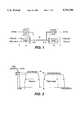
- FIG. 1illustrates a schematic diagram of a typical system of the type used in the present invention
- FIG. 2illustrates the frequency domain multiplexing which is used by the system in accordance with the present invention
- FIG. 3is a diagram illustrating the synchronization signals received by the receiver in response to the receiver's receipt of the PN signal transmitted by the transmitting transceiver when communications are established.
- FIG. 4is a block diagram of the startup handshake/data signal generator of the present invention.
- FIG. 5is a flow chart illustrating the startup procedure used by the preferred embodiment of the transmitting transceiver of the present invention
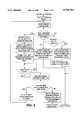
- FIG. 6is a flow chart illustrating the startup procedure used by the preferred embodiment of the receiving transceiver of the present invention.
- FIG. 7is a block diagram of the auto-baud/fixed baud state diagram in accordance with the preferred embodiment of the present invention.
- FIG. 8is a flow chart illustrating the procedure used by the preferred embodiment of the invention for performing auto-baud
- FIG. 9illustrates the constellation used during the initial handshake
- FIG. 10is a high level depiction illustrating the startup signals on the subscriber line.
- a system 10 employing Rate Adaptive Digital Subscriber Line (“RADSL”) transceivers 12, 14 based upon the Carrierless AM/PM (“CAP") modulation schemeis illustrated in FIG. 1.
- RADSLRate Adaptive Digital Subscriber Line
- CAPCarrierless AM/PM
- FIG. 1a system 10 employing Rate Adaptive Digital Subscriber Line (“RADSL”) transceivers 12, 14 based upon the Carrierless AM/PM (“CAP") modulation scheme is illustrated in FIG. 1.
- RADSL modem, or transceiver 12located at a customer's location
- a complementary RADSL transceiver 14located at the central office of the local telephone company.
- the transceivers 12, 14are connected together over a communications channel 16 which generally comprises a standard twisted pair of metal wires, of the type long used in Plain Old Telephone Systems (“POTS").
- POTSPlain Old Telephone Systems
- the transceivers 12, 14are able to communicate digital data between their respective locations at extremely high data rates.
- bit rates ranging from approximately 600 kb/s to approximately 7 MB/scan be achieved for data transferred from the network (central office) to the customer premises, and bit rates of approximately 200 kb/s to 1 Mb/s can be achieved for data transferred from the customer premises to the network.
- the foregoingis accomplished by use of a number of techniques, described herein, which enable the data to be modulated and transmitted over the POTS system.
- one technique used by the present inventionis to separate the bandwidth of the line whereby the actual data being transmitted "upstream”, i.e., from the customer's location to the network, is transmitted in a first band 18, having a frequency which runs upward from f 1 , while the data which is transmitted "downstream", i.e., from the network to the customer's location, is transmitted in a second, higher frequency band 20, which has a frequency which runs upward from f 2 .
- the highest frequency in the upstream band 18is separate (i.e., lower than) from the lowest frequency, f 2 , in the downstream band 20.
- the lowest frequency, f 1in the upstream band 18 separated from, and higher than, the typical POTS frequency of 4 kHz.
- the transceivers 12, 14 of FIG. 1are each transmitting over the communications channel 16 in different frequency ranges 18, 20, as illustrated in FIG. 2. Further, in accordance with the present invention, as the ability to achieve the highest possible data transfer rates in a particular objective of the invention, it is not necessary to have both of the transceivers 12, 14 transmitting at the same rate. Accordingly, it is within the scope of the invention to have either the customer's transceiver 12, or (more typically) the network transceiver 14 transmitting at a higher data rate. Thus, it is within the scope of the invention to have the transceivers 12, 14 provide for asymmetrical data transmission rates.
- An objective, therefore, of the present inventionis to provide a means by which the transceivers 12, 14 can establish a reliable connection with one another while maximizing their ability to reliably transmit data at the highest possible rates.
- the present inventionprovides a means by which the transceivers 12, 14 can initialize communications and establish the highest possible data transmission rates over the communications channel 16, which is comprised of a metal twisted pair which extends between the customer's location and the network.
- the present inventionrequires a robust scheme for providing the initial start-up of communication between the transceivers 12, 14.
- the intent of this start-up procedureis to allow the transceivers 12, 14 to establish their initial handshake, perform rate negotiation, provide a symbol/baud rate, and transfer such other information as fast, reliable communications require.
- tellationrefers to a mechanism by which a data bit stream can be converted into symbols for transmission over the communications channel 16.
- the "size" of the constellationis determined by the number of bits which can be encoded into each symbol, while the largest size constellation which can be transferred over the communications channel 16 is determined by the quality of the communications channel 16.
- the larger the constellationmeaning the greater the number of data bits which are encoded, on a per symbol basis
- the higher the data transfer rate over the channelif a particular channel 16 is able to support both a high symbol rate and a large constellation, a high data transfer rate will be supported on the channel 16. Accordingly, it is an objective of the present invention to determine both the highest symbol rate and the largest constellation which can be reliably supported on the channel 16.
- a handshake/data signal generator 22, illustrated in FIG. 4is used to perform the rate negotiation of the RADSL transceivers 12, 14 of the present invention.
- the inventionemploys a RADSL transceiver which is able to support a predetermined, finite set of constellations and baud rates, one of which will be selected for each startup.
- a RADSL transceiverwhich is able to support a predetermined, finite set of constellations and baud rates, one of which will be selected for each startup.
- there is an initial training sequencewhich uses an extremely robust scheme to assure detection. This is needed, because at startup the receive and the timing recovery function are not yet operational.
- the scheme selected for use in the preferred embodiment of the inventionuses a binary pseudorandom number ("PN") sequence which is spread over a large number of symbols.
- PNbinary pseudorandom number
- the PNis 63 symbols long, although other values (preferably of the form, 2 n -1, may be used). Since the information in the PN is spread over many symbols, detection is very reliable and robust, so can be made without the need for adaptive filters or timing recovery.
- the benefit of using the PNis that a synchronization detection device, in the receiver, can use a correlator, which matches the synchronization signal, and yields distinctive signal characteristics which can be used to differentiate the synchronization signal from the data signal in noisy environments. In the present invention, this feature is used to provide a particular training signal to the receiver.
- the handshake of the present inventionis highly robust in that it is preferably based upon a PN having a length of 63 symbols.
- the long PN sequenceallows the receiving transceiver 14 to use a correlator to uniquely identify that the transmitting transceiver 12 has, in fact, sent a "1".
- the sending transceiver 12in order for the sending transceiver 12 to send a "0" bit, it will send 63 zero symbols.
- This ability of the synchronization detection device in the receiving transceiver 14 to differentiate the synchronization signal from the data signal in a noisy environmentis based upon the use of the PN sequence in the header of the transmitted signal.
- the correlatorproduces a high value (peak) when there is a match and low values (quiet zone) otherwise. Since the sequence is repeated, information known, a priori, about the periodicity and the width of the peaks and quiet zones can be used to enhance detection reliability. Accordingly, the particular synchronization pattern used, has distinctive properties in its autocorrelation function, so its use preferably improves the synchronization reliability of the system. This feature of the invention is the reason for using the PN in the header.
- the "wake up" sequence used by the transmitteris illustrated to be a continuous PN header.
- the correlator in the receivercontinuously looks for a "1", which corresponds to the recognition of the arrival of the PN.
- the receiverUpon receipt of a valid PN signal, as illustrated at 102, 104, 106, the receiver continues to look for either a "1", corresponding to the receipt of another PN signal following a time period indicated by the PN window 108.
- the receiverlooks for a high signal, representative of a "1" bit during a time period represented by the peak detect windows 110, 112, 114, 116, 118.
- these peak detect windows 110, 112, 114, 116, 118are time periods at the end of a PN window during which a bit is expected. Consequently, if the correlator indicates the present of a high signal, as shown at 102, 104, and during the peak detect windows 110, 114, 116, 118, then a "1" is recognized by the receiver. Alternatively, if there is no high signal present, as illustrated in the peak detect window 112, then a "0" bit is presumed to have been sent.
- the present inventionuses a particular data format in the preferred embodiment so that the receiver can both receive data of unspecified length, and remain synchronized with the transmitter, using only the correlator, and without actual synchronization.
- the format of the trailer informationis preferably in the form of 8-bit bytes which follow the "wake-up" signal 100.
- the indication to the receiver that the "wake up" signal 100 has ended and that trailer data is about to be sentis the presence of a "0" bit ("start bit"), as illustrated at 112. Following the transmission of the start bit, ST, the transmitter will send data bits in 8-bit bytes.
- every eighth biti.e., bits I 7 , I 15 , I 23 , I 31 , . . .
- every eighth bitwill be used as a "continuation bit”, and it will be set to either a "1", to indicate that another data byte is to be sent, or to a "0", to indicate that the byte just sent was the last byte to be sent.
- a parity bit and two stop bitsare transmitted in the preferred embodiment of the invention, which happens to use odd parity.
- a particular advantage of using a "1" as the continuation bitis that its presence may be used by the receiver to keep the receiver in synchronization with the transmitter by restarting the PN window, and thereby recentering the peak detect window around the expected time of receipt of the continuation bit, upon the receipt of each continuation bit.
- the handshakestarts with a transmitter operating at the low predetermined baud rate which has previously been established.
- the low baud rateprovides the maximum loop reach for the transmitter.
- the use of a common, low baud rateguarantees the compatibility with other RADSL products.
- the first thing which two transceivers 12, 14 negotiateis the symbol rate which they will use. Since the constellation size (i.e., its bit/baud, or bit/symbol size) does not effect the frequency placement or the bandwidth the transmitter is using, the selection is preferably negotiated at the end of the startup using receive signal to noise ratio measurements.
- Modems of the prior artsuch as CCITT standard V.34 modems, initialized communications with one another by first listing which the baud rates they supported. Then they went into a test mode to determine which of the supported baud rates was the highest one which could be used for each new connection. They perform this testing anew each time a connection is made.
- a transceiver 12 built in accordance with the present inventionnegotiates its symbol rate by first sending a list of the symbol rates which is can support. Then it sends a request to use a particular one of the supported baud rates, but no testing is performed. This can be accomplished by the modems 12, 14 of the present invention, as they are always being used to connect to each other over the same line 16. Due to the fixed line 16 between the modems 12, 14, once testing has been accomplished, and the test results have been stored, there is generally no need to retest on each new connection.
- modems 12, 14 of the present inventiondiffers from those known in the prior art in the event that it becomes necessary to change baud rates due to changes in the line condition. Accordingly, in the event that it becomes necessary to change baud rates due to changes in the line condition, the other transceiver 14 will already known the baud rates which the transceiver 12 can support. Thus, if the modems 12, 14 recognize that they are experiencing a very low error rate over a suitable time period, they can agree to go to a higher baud rate, if they are already aware that a higher, commonly available baud rate is supported. Alternatively, they can go to a lower, commonly supported baud rate if line conditions indicate that too many errors have occurred during some period.
- the number of bits/symboli.e., bits/baud
- other parametersincluding Tomlinson precoder coefficients and forward error correction parameters, such as frame size and interleaving depth, which are used by Reed-Solomon ("RS") codes
- RSReed-Solomon
- Other datasuch as the error count and the signal to noise ratio accumulated during the last startup period in which auto-baud testing (see below) was used, can also be transferred, and it is transferred in the preferred embodiment of the invention.
- the transceivers 12, 14can operate either in fixed mode, or in auto-baud mode.
- the use of auto-baud modeis determined by an initial request made by either modem 12, 14 when communications are established. The determination of which mode to select is included in the trailer data of the initial entry.
- the transceiver 12when a transceiver 12 operates in fixed mode the transceiver 12 requests a single baud rate to establish the connection, although, as always, all of the available baud rates are preferably listed. The lowest common symbol rate which exists between the transceivers 12, 14 will be used.
- the transceivers 12, 14will go into a timed testing mode in which the signal quality and error rate are measured for all possible configurations. The results are then stored and used to request a fixed baud rate connection.
- a feature of the present inventionis that optimum constellation, RS frame size, and interleaving depth can be determined at the end of the receiver training period and before startup is completed.
- Yet another feature, which is of commercial interest to the network owneris the ability to limit the maximum rate at which the transceiver 14 will operate based upon subscription options selected by particular customers. For example, if a customer's transceiver 12 is capable of receiving at 7 Mb/s, but the customer has selected only 1 Mb/s service, then the network owner can program its RADSL transceiver 14 to provide no more than 1 Mb/s service to the transceiver 12.
- the handshake/data signal generator 22accepts serial data into a scrambler 24 on a data line 26.
- the specific bit to symbol mapping which is usedis determined by the startup state machine 30 which also controls various other devices, such as the multiplexers 32, 34, and the symbol/baud and clock generator 36.
- a PNis used during the initial handshake.
- the PNis generated by a PN symbol generator, which provides one of the possible inputs into a multiplexer 40.
- a zero symbol generator 42represented by the "0" symbol provides the other possible input into the multiplexer 40.
- the inputwhether a "1", i.e., the PN, or a "0", from the zero symbol generator 42, is at least 63 symbols long in the preferred embodiment of the invention.
- the data which is actually sent by the multiplexer 40is determined by the initial handshake and rate negotiation which the RADSL transceiver performs.
- the output of the multiplexer 40provides an input into the multiplexer 32, whose output, in turn, is an input into the multiplexer 34.
- the output of multiplexer 34goes through a filter 44 and a digital to analog (“D/A”) converter 46, from which it exists as an analog transmit signal on line 48.
- D/Adigital to analog
- the final handshake negotiation exchangein which Tomlinson precoder coefficients, forward error correction parameters (e.g., RS codes), final baud rate, and constellation settings are transmitted, are accomplished using the multiplexer 50, whose output also goes to multiplexer 32, and then ultimately out onto the line 48 as an analog signal.
- the inputs to multiplexer signalshown as "A”, "B”, “C”, and “D", are representative of the data which is sent during the final handshake.
- the initial handshakefor purposes of maintaining a robust system, uses the constellation illustrated in FIG. 9 for data exchange, as it is highly error resistant.
- a flow chart illustrating the initial handshake procedureis shown.
- a continuous PN CAP signalis sent.
- a 63 symbol PNis sent to represent a data bit of "1”
- a 63 symbol "0" symbolis sent to represent a data bit of "0”.
- datais transmitted using the coding scheme described to transmit bits which make up bytes.
- the operation of the receiving transceiver 14is illustrated in a flow chart. As illustrated, the transceiver 14 continuously searches for a sequence corresponding to a PN. Upon detecting the wake up sequence using the PN correlator, the transceiver 14 looks for a start bit, and follows a procedure which is complementary to that set forth above, the details of which are set forth in the flow chart of FIG. 6.
- FIGS. 7 and 8the auto-baud operation of a transceiver 12 (at the customer's location, CP) and a transceiver 14 (at the central office, CO) are shown.
- the transceivers 12, 14,are controlled by state machines 60 which control data transmission and reception through multiplexers 62.
- Test generators 64which supply inputs to the multiplexers 62, are used, as will be explained with reference to the flow chart of FIG. 8, to generate data which is used by the other transceiver to detect errors using an error rate detector 66.
- the state machines 60are able to collect data from the error rate detectors 66 and store that data in an appropriate memory storage means 68.
- the auto-baud testin accordance with the preferred embodiment of the invention, is described. As illustrated in the flow chart, if an auto-baud test is requested, information about the length of the test will be transmitted. Assuming that the test is successfully completed, the highest allowed baud and optimum constellation for the user programmable noise margin will be selected. As illustrated in the flow chart, if no auto-baud test is selected, the results which were stored when the last, prior auto-baud test will be used. Alternatively, if no auto-baud test was ever completely performed, then the transceivers will start using the lowest baud, or, alternatively, by using a user programmed baud rate.
- the PNis used in the present invention to actually send data, as well as for the initial synchronization.
- This encoding of actual data onto the PNis relatively slow, as it takes 63 symbols (in the preferred embodiment) to send a single bit.
- the transceiversexchange information about themselves, including both the desired symbol rates, and the list of available symbol rates. This negotiation, is based entirely upon the trailer, rather than on line testing.
- transceiversuse frequency division multiplexing, to separate the upstream and downstream data, together with symbol negotiation.
Landscapes
- Engineering & Computer Science (AREA)
- Signal Processing (AREA)
- Computer Networks & Wireless Communication (AREA)
- Communication Control (AREA)
- Bidirectional Digital Transmission (AREA)
Abstract
Description
Claims (21)
Priority Applications (4)
| Application Number | Priority Date | Filing Date | Title |
|---|---|---|---|
| US08/690,243US5751701A (en) | 1996-07-19 | 1996-07-19 | Rate adaptive digital subscriber line ("RADSL") modem |
| PCT/US1997/009443WO1998004060A1 (en) | 1996-07-19 | 1997-06-02 | Rate adaptive digital subscriber line ('radsl') modem |
| TW086109594ATW362206B (en) | 1996-07-19 | 1997-07-08 | Rate adaptive digital subscriber line ("RADSL") modem |
| US09/016,994US6167034A (en) | 1996-07-19 | 1998-02-02 | Rate adaptive digital subscriber line (RADSL) modem |
Applications Claiming Priority (1)
| Application Number | Priority Date | Filing Date | Title |
|---|---|---|---|
| US08/690,243US5751701A (en) | 1996-07-19 | 1996-07-19 | Rate adaptive digital subscriber line ("RADSL") modem |
Related Child Applications (1)
| Application Number | Title | Priority Date | Filing Date |
|---|---|---|---|
| US09/016,994ContinuationUS6167034A (en) | 1996-07-19 | 1998-02-02 | Rate adaptive digital subscriber line (RADSL) modem |
Publications (1)
| Publication Number | Publication Date |
|---|---|
| US5751701Atrue US5751701A (en) | 1998-05-12 |
Family
ID=24771694
Family Applications (2)
| Application Number | Title | Priority Date | Filing Date |
|---|---|---|---|
| US08/690,243Expired - LifetimeUS5751701A (en) | 1996-07-19 | 1996-07-19 | Rate adaptive digital subscriber line ("RADSL") modem |
| US09/016,994Expired - LifetimeUS6167034A (en) | 1996-07-19 | 1998-02-02 | Rate adaptive digital subscriber line (RADSL) modem |
Family Applications After (1)
| Application Number | Title | Priority Date | Filing Date |
|---|---|---|---|
| US09/016,994Expired - LifetimeUS6167034A (en) | 1996-07-19 | 1998-02-02 | Rate adaptive digital subscriber line (RADSL) modem |
Country Status (3)
| Country | Link |
|---|---|
| US (2) | US5751701A (en) |
| TW (1) | TW362206B (en) |
| WO (1) | WO1998004060A1 (en) |
Cited By (48)
| Publication number | Priority date | Publication date | Assignee | Title |
|---|---|---|---|---|
| US5852630A (en)* | 1997-07-17 | 1998-12-22 | Globespan Semiconductor, Inc. | Method and apparatus for a RADSL transceiver warm start activation procedure with precoding |
| WO1999031813A3 (en)* | 1997-12-16 | 1999-08-26 | 3Com Corp | System and method for user information transfer before modem connection |
| US5999540A (en)* | 1998-12-22 | 1999-12-07 | Cisco Technology, Inc. | Rate adaptive XDSL communication system and method |
| WO1999067890A1 (en)* | 1998-06-23 | 1999-12-29 | Pc Tel, Inc. | Spread spectrum handshake for digital subscriber line telecommunications systems |
| US6073179A (en)* | 1997-06-30 | 2000-06-06 | Integrated Telecom Express | Program for controlling DMT based modem using sub-channel selection to achieve scaleable data rate based on available signal processing resources |
| US6130882A (en)* | 1997-09-25 | 2000-10-10 | Motorola, Inc. | Method and apparatus for configuring a communication system |
| US6161203A (en)* | 1997-10-03 | 2000-12-12 | Conexant Systems, Inc. | Communication system utilizing Reed-Solomon code to achieve auto frame synchronization acquistion |
| US6160843A (en)* | 1996-03-29 | 2000-12-12 | Cisco Technology, Inc. | Communication server apparatus providing XDSL services and method |
| US6163599A (en)* | 1997-03-20 | 2000-12-19 | Cisco Technology, Inc. | Communication server apparatus and method |
| US6167034A (en)* | 1996-07-19 | 2000-12-26 | Globespan Technologies, Inc. | Rate adaptive digital subscriber line (RADSL) modem |
| US6169788B1 (en) | 1996-03-29 | 2001-01-02 | Cisco Technology, Inc. | Communication server apparatus having distributed switching and method |
| US6181711B1 (en)* | 1997-06-26 | 2001-01-30 | Cisco Systems, Inc. | System and method for transporting a compressed video and data bit stream over a communication channel |
| US6201830B1 (en)* | 1997-06-11 | 2001-03-13 | Texas Instruments Incorporated | Low computation idle transmission method for DSL modems |
| US6266350B1 (en) | 1998-03-09 | 2001-07-24 | Broadcom Homenetworking, Inc. | Off-line broadband network interface |
| US6353628B1 (en)* | 1998-12-15 | 2002-03-05 | Nortel Networks Limited | Apparatus, method and system having reduced power consumption in a multi-carrier wireline environment |
| US6374288B1 (en) | 1999-01-19 | 2002-04-16 | At&T Corp | Digital subscriber line server system and method for dynamically changing bit rates in response to user requests and to message types |
| US6385203B2 (en)* | 1996-03-29 | 2002-05-07 | Cisco Technology, Inc. | Communication server apparatus and method |
| US6388990B1 (en)* | 1998-12-18 | 2002-05-14 | Covad Communications Company | Method and system for reducing congestion in connection-oriented packet networks having digital subscriber line access |
| US20030112859A1 (en)* | 2001-12-13 | 2003-06-19 | Alcatel | Modem system and modems with tunable analog filters |
| US6731678B1 (en) | 2000-10-30 | 2004-05-04 | Sprint Communications Company, L.P. | System and method for extending the operating range and/or increasing the bandwidth of a communication link |
| US6763097B1 (en) | 1999-06-24 | 2004-07-13 | Coppergate Communications Ltd. | Source adaptive digital subscriber line and method |
| US6771697B1 (en) | 1998-06-23 | 2004-08-03 | Pctel, Inc. | Spread spectrum handshake for digital subscriber line telecommunications systems |
| US6804267B1 (en) | 1997-10-25 | 2004-10-12 | Centillium Communications, Inc. | Transceiver training for DSL modems under TCM-ISDN interference |
| US20050055466A1 (en)* | 2003-09-10 | 2005-03-10 | Nec Corporation | Automatic network provisioning system |
| US7003580B1 (en) | 2000-12-29 | 2006-02-21 | Sprint Communications Company L.P. | Bandwidth boost using a wireless communication path |
| US7170938B1 (en) | 2001-08-21 | 2007-01-30 | Cisco Systems Canada Co. | Rate control method for video transcoding |
| US7295569B1 (en)* | 2003-03-07 | 2007-11-13 | Cisco Technology, Inc. | Selecting a profile for an interface of a network device according to a margin |
| US7295570B1 (en)* | 2003-03-07 | 2007-11-13 | Cisco Technology, Inc. | Determining a profile for an interface of a network device |
| US7299295B1 (en)* | 2000-11-16 | 2007-11-20 | Cisco Technology, Inc. | High-speed dial-up modem session startup method and apparatus |
| US7366236B1 (en) | 2001-06-04 | 2008-04-29 | Cisco Sytems Canada Co. | Source adaptive system and method for 2D iDCT |
| US20080220725A1 (en)* | 2007-03-09 | 2008-09-11 | Infineon Technologies Ag | Data transmission method, communication system, transceiver, transmitter and receiver |
| US7477688B1 (en) | 2000-01-26 | 2009-01-13 | Cisco Technology, Inc. | Methods for efficient bandwidth scaling of compressed video data |
| US20090060151A1 (en)* | 1999-07-20 | 2009-03-05 | Serconet, Ltd | Network for telephony and data communication |
| US7593394B2 (en) | 2000-04-18 | 2009-09-22 | Mosaid Technologies Incorporated | Telephone communication system over a single telephone line |
| US7593426B1 (en) | 2003-05-09 | 2009-09-22 | The Board Of Trustees Of The Leland Stanford Junior University | Bit rate and power allocation for multi-carrier communication systems |
| US7633966B2 (en) | 2000-04-19 | 2009-12-15 | Mosaid Technologies Incorporated | Network combining wired and non-wired segments |
| US7656949B1 (en) | 2001-06-27 | 2010-02-02 | Cisco Technology, Inc. | Methods and apparatus for performing efficient inverse transform operations |
| US7680255B2 (en) | 2001-07-05 | 2010-03-16 | Mosaid Technologies Incorporated | Telephone outlet with packet telephony adaptor, and a network using same |
| US7686653B2 (en) | 2003-09-07 | 2010-03-30 | Mosaid Technologies Incorporated | Modular outlet |
| US7702095B2 (en) | 2003-01-30 | 2010-04-20 | Mosaid Technologies Incorporated | Method and system for providing DC power on local telephone lines |
| US7715534B2 (en) | 2000-03-20 | 2010-05-11 | Mosaid Technologies Incorporated | Telephone outlet for implementing a local area network over telephone lines and a local area network using such outlets |
| US7746905B2 (en) | 2003-03-13 | 2010-06-29 | Mosaid Technologies Incorporated | Private telephone network connected to more than one public network |
| US7779134B1 (en) | 2003-02-25 | 2010-08-17 | Cisco Technology, Inc. | Using modem profiles to improve connectivity, connect timing, and compression performance on a modem relay (MR) gateway |
| US7965735B2 (en) | 1998-07-28 | 2011-06-21 | Mosaid Technologies Incorporated | Local area network of serial intelligent cells |
| US7990908B2 (en) | 2002-11-13 | 2011-08-02 | Mosaid Technologies Incorporated | Addressable outlet, and a network using the same |
| US8582598B2 (en) | 1999-07-07 | 2013-11-12 | Mosaid Technologies Incorporated | Local area network for distributing data communication, sensing and control signals |
| US8611528B2 (en) | 2004-02-16 | 2013-12-17 | Mosaid Technologies Incorporated | Outlet add-on module |
| US10986164B2 (en) | 2004-01-13 | 2021-04-20 | May Patents Ltd. | Information device |
Families Citing this family (14)
| Publication number | Priority date | Publication date | Assignee | Title |
|---|---|---|---|---|
| DE19814439A1 (en)* | 1998-03-31 | 1999-10-07 | Siemens Ag | Communication arrangement for the connection of a communication terminal to services of different communication networks |
| JPH11355435A (en)* | 1998-06-11 | 1999-12-24 | Fujitsu Ltd | High-speed communication system, subscriber transmission device, subscriber device, and communication service setting method |
| US6760383B1 (en)* | 1999-03-09 | 2004-07-06 | Nortel Networks Limited | Long reach SDSL system spectrally compatible with ADSL systems |
| US6700927B1 (en)* | 1999-03-10 | 2004-03-02 | Next Level Communications, Inc. | Method for establishing and adapting communication link parameters in XDSL transmission systems |
| US6535551B1 (en)* | 1999-11-17 | 2003-03-18 | Conexant Systems, Inc. | DSL post-synchronization auto baud |
| US6570915B1 (en)* | 1999-11-17 | 2003-05-27 | Conexant Systems, Inc. | DSL auto baud |
| US6985521B1 (en)* | 2000-01-07 | 2006-01-10 | Ikanos Communication, Inc | Method and apparatus for channel estimation for X-DSL communications |
| WO2002102043A1 (en)* | 2001-06-07 | 2002-12-19 | Aware, Inc. | Variable state length initialization for dsl systems |
| US7130337B2 (en)* | 2001-07-02 | 2006-10-31 | Phonex Broadband Corporation | Method and system for sample and recreation synchronization for digital transmission of analog modem signal |
| US6539081B2 (en) | 2001-07-20 | 2003-03-25 | Adtran Inc. | Method of establishing signaling rate for single-line digital subscriber link providing extended range ADSL service with auxiliary pots channel |
| US6775550B2 (en)* | 2001-07-20 | 2004-08-10 | Adtran, Inc. | Method of inducing ADSL communication device to transmit at downstream signaling rate optimized for extended range ADSL service with auxiliary pots channel over SDSL link |
| US7031346B2 (en)* | 2001-07-20 | 2006-04-18 | Adtran, Inc. | System for providing extended range ADSL service with auxiliary pots channel over single-line digital subscriber link |
| US6952430B2 (en)* | 2001-12-31 | 2005-10-04 | Globespanvirata Incorporated | System and method for interfacing a data link protocol engine and a physical layer |
| JP4680255B2 (en)* | 2005-03-22 | 2011-05-11 | 富士通株式会社 | Information transmission apparatus and information transmission method |
Citations (7)
| Publication number | Priority date | Publication date | Assignee | Title |
|---|---|---|---|---|
| EP0112953A1 (en)* | 1982-12-28 | 1984-07-11 | International Business Machines Corporation | Method of dynamic assignment of speeds in a multiplex transmission system |
| US4756007A (en)* | 1984-03-08 | 1988-07-05 | Codex Corporation | Adaptive communication rate modem |
| US4802189A (en)* | 1983-03-25 | 1989-01-31 | Siemens Aktiengesellshaft | Method and circuit arrangement for the transmission of data signals between subscriber stations of a data network |
| US5023869A (en)* | 1989-03-27 | 1991-06-11 | Alberta Telecommunications Research Centre | Method and apparatus for maximizing the transmission capacity of a multi-channel bidirectional communications link |
| US5394392A (en)* | 1992-12-14 | 1995-02-28 | At&T Corp. | Method for transferring information using modems |
| US5450438A (en)* | 1993-07-26 | 1995-09-12 | At&T Corp. | Fallback method to 1200 bits per second for use in mobile radio |
| US5541955A (en)* | 1992-11-06 | 1996-07-30 | Pericle Communications Company | Adaptive data rate modem |
Family Cites Families (2)
| Publication number | Priority date | Publication date | Assignee | Title |
|---|---|---|---|---|
| US5751701A (en)* | 1996-07-19 | 1998-05-12 | Globespan Technologies, Inc. | Rate adaptive digital subscriber line ("RADSL") modem |
| US6031848A (en)* | 1997-05-07 | 2000-02-29 | 3Com Corporation | Apparatus for an improved ISDN terminal adapter having baud rate unblocking and methods for use therein |
- 1996
- 1996-07-19USUS08/690,243patent/US5751701A/ennot_activeExpired - Lifetime
- 1997
- 1997-06-02WOPCT/US1997/009443patent/WO1998004060A1/enactiveApplication Filing
- 1997-07-08TWTW086109594Apatent/TW362206B/ennot_activeIP Right Cessation
- 1998
- 1998-02-02USUS09/016,994patent/US6167034A/ennot_activeExpired - Lifetime
Patent Citations (7)
| Publication number | Priority date | Publication date | Assignee | Title |
|---|---|---|---|---|
| EP0112953A1 (en)* | 1982-12-28 | 1984-07-11 | International Business Machines Corporation | Method of dynamic assignment of speeds in a multiplex transmission system |
| US4802189A (en)* | 1983-03-25 | 1989-01-31 | Siemens Aktiengesellshaft | Method and circuit arrangement for the transmission of data signals between subscriber stations of a data network |
| US4756007A (en)* | 1984-03-08 | 1988-07-05 | Codex Corporation | Adaptive communication rate modem |
| US5023869A (en)* | 1989-03-27 | 1991-06-11 | Alberta Telecommunications Research Centre | Method and apparatus for maximizing the transmission capacity of a multi-channel bidirectional communications link |
| US5541955A (en)* | 1992-11-06 | 1996-07-30 | Pericle Communications Company | Adaptive data rate modem |
| US5394392A (en)* | 1992-12-14 | 1995-02-28 | At&T Corp. | Method for transferring information using modems |
| US5450438A (en)* | 1993-07-26 | 1995-09-12 | At&T Corp. | Fallback method to 1200 bits per second for use in mobile radio |
Cited By (95)
| Publication number | Priority date | Publication date | Assignee | Title |
|---|---|---|---|---|
| US6160843A (en)* | 1996-03-29 | 2000-12-12 | Cisco Technology, Inc. | Communication server apparatus providing XDSL services and method |
| US6385203B2 (en)* | 1996-03-29 | 2002-05-07 | Cisco Technology, Inc. | Communication server apparatus and method |
| US20050141563A1 (en)* | 1996-03-29 | 2005-06-30 | Cisco Technology, Inc., A California Corporation | Communication server apparatus providing XDSL services and method |
| US6870834B1 (en) | 1996-03-29 | 2005-03-22 | Cisco Technology, Inc. | Communication server apparatus providing XDSL services and method |
| US6169788B1 (en) | 1996-03-29 | 2001-01-02 | Cisco Technology, Inc. | Communication server apparatus having distributed switching and method |
| US8116298B2 (en) | 1996-03-29 | 2012-02-14 | Cisco Technology, Inc. | Communication server apparatus providing XDSL services and method |
| US6167034A (en)* | 1996-07-19 | 2000-12-26 | Globespan Technologies, Inc. | Rate adaptive digital subscriber line (RADSL) modem |
| US6163599A (en)* | 1997-03-20 | 2000-12-19 | Cisco Technology, Inc. | Communication server apparatus and method |
| US6201830B1 (en)* | 1997-06-11 | 2001-03-13 | Texas Instruments Incorporated | Low computation idle transmission method for DSL modems |
| US6891854B2 (en) | 1997-06-26 | 2005-05-10 | Cisco Technology, Inc. | System and method for transporting a compressed video and data bit stream over a communication channel |
| US6181711B1 (en)* | 1997-06-26 | 2001-01-30 | Cisco Systems, Inc. | System and method for transporting a compressed video and data bit stream over a communication channel |
| US7505480B1 (en) | 1997-06-26 | 2009-03-17 | Cisco Technology, Inc. | System and method for transporting a compressed video and data bit stream over a communication channel |
| US6073179A (en)* | 1997-06-30 | 2000-06-06 | Integrated Telecom Express | Program for controlling DMT based modem using sub-channel selection to achieve scaleable data rate based on available signal processing resources |
| WO1999004501A1 (en)* | 1997-07-17 | 1999-01-28 | Globespan Semiconductor Inc. | Method and apparatus for a radsl transceiver warm start activation procedure with precoding |
| US5852630A (en)* | 1997-07-17 | 1998-12-22 | Globespan Semiconductor, Inc. | Method and apparatus for a RADSL transceiver warm start activation procedure with precoding |
| US6130882A (en)* | 1997-09-25 | 2000-10-10 | Motorola, Inc. | Method and apparatus for configuring a communication system |
| US6775241B1 (en) | 1997-09-25 | 2004-08-10 | Freescale Semiconductor, Inc. | Method and apparatus for configuring a communication system |
| US6161203A (en)* | 1997-10-03 | 2000-12-12 | Conexant Systems, Inc. | Communication system utilizing Reed-Solomon code to achieve auto frame synchronization acquistion |
| US6804267B1 (en) | 1997-10-25 | 2004-10-12 | Centillium Communications, Inc. | Transceiver training for DSL modems under TCM-ISDN interference |
| US6317455B1 (en)* | 1997-12-16 | 2001-11-13 | 3Com Corporation | System and method for user information transfer before modem connection |
| WO1999031813A3 (en)* | 1997-12-16 | 1999-08-26 | 3Com Corp | System and method for user information transfer before modem connection |
| US7440410B2 (en) | 1998-03-09 | 2008-10-21 | Broadcom Corporation | Off-line broadband network interface |
| US7142553B1 (en) | 1998-03-09 | 2006-11-28 | Broadcom Corporation | Off-line broadband network interface |
| US6266350B1 (en) | 1998-03-09 | 2001-07-24 | Broadcom Homenetworking, Inc. | Off-line broadband network interface |
| US20090040940A1 (en)* | 1998-03-09 | 2009-02-12 | Eric Ojard | Off-line broadband network interface |
| US6760347B1 (en) | 1998-03-09 | 2004-07-06 | Broadcom Corporation | Off-line broadband network interface |
| US6850493B1 (en) | 1998-03-09 | 2005-02-01 | Broadcom Corporation | Off-line broadband network interface |
| US20040252648A1 (en)* | 1998-03-09 | 2004-12-16 | Broadcom Corporation | Off-line broadband network interface |
| US6771697B1 (en) | 1998-06-23 | 2004-08-03 | Pctel, Inc. | Spread spectrum handshake for digital subscriber line telecommunications systems |
| WO1999067890A1 (en)* | 1998-06-23 | 1999-12-29 | Pc Tel, Inc. | Spread spectrum handshake for digital subscriber line telecommunications systems |
| US8867523B2 (en) | 1998-07-28 | 2014-10-21 | Conversant Intellectual Property Management Incorporated | Local area network of serial intelligent cells |
| US7986708B2 (en) | 1998-07-28 | 2011-07-26 | Mosaid Technologies Incorporated | Local area network of serial intelligent cells |
| US8885660B2 (en) | 1998-07-28 | 2014-11-11 | Conversant Intellectual Property Management Incorporated | Local area network of serial intelligent cells |
| US8908673B2 (en) | 1998-07-28 | 2014-12-09 | Conversant Intellectual Property Management Incorporated | Local area network of serial intelligent cells |
| US7965735B2 (en) | 1998-07-28 | 2011-06-21 | Mosaid Technologies Incorporated | Local area network of serial intelligent cells |
| US8325636B2 (en) | 1998-07-28 | 2012-12-04 | Mosaid Technologies Incorporated | Local area network of serial intelligent cells |
| US8885659B2 (en) | 1998-07-28 | 2014-11-11 | Conversant Intellectual Property Management Incorporated | Local area network of serial intelligent cells |
| US6353628B1 (en)* | 1998-12-15 | 2002-03-05 | Nortel Networks Limited | Apparatus, method and system having reduced power consumption in a multi-carrier wireline environment |
| US6388990B1 (en)* | 1998-12-18 | 2002-05-14 | Covad Communications Company | Method and system for reducing congestion in connection-oriented packet networks having digital subscriber line access |
| US6389065B1 (en) | 1998-12-22 | 2002-05-14 | Cisco Technology Inc. | Rate adaptive XDSL communication system and method |
| US5999540A (en)* | 1998-12-22 | 1999-12-07 | Cisco Technology, Inc. | Rate adaptive XDSL communication system and method |
| US6374288B1 (en) | 1999-01-19 | 2002-04-16 | At&T Corp | Digital subscriber line server system and method for dynamically changing bit rates in response to user requests and to message types |
| US6763097B1 (en) | 1999-06-24 | 2004-07-13 | Coppergate Communications Ltd. | Source adaptive digital subscriber line and method |
| US8582598B2 (en) | 1999-07-07 | 2013-11-12 | Mosaid Technologies Incorporated | Local area network for distributing data communication, sensing and control signals |
| US8929523B2 (en) | 1999-07-20 | 2015-01-06 | Conversant Intellectual Property Management Inc. | Network for telephony and data communication |
| US8351582B2 (en) | 1999-07-20 | 2013-01-08 | Mosaid Technologies Incorporated | Network for telephony and data communication |
| US20090060151A1 (en)* | 1999-07-20 | 2009-03-05 | Serconet, Ltd | Network for telephony and data communication |
| US7477688B1 (en) | 2000-01-26 | 2009-01-13 | Cisco Technology, Inc. | Methods for efficient bandwidth scaling of compressed video data |
| US20090097551A1 (en)* | 2000-01-26 | 2009-04-16 | Cisco Technology, Inc. | Methods for Efficient Bandwidth Scaling of Compressed Video Data |
| US8363797B2 (en) | 2000-03-20 | 2013-01-29 | Mosaid Technologies Incorporated | Telephone outlet for implementing a local area network over telephone lines and a local area network using such outlets |
| US8855277B2 (en) | 2000-03-20 | 2014-10-07 | Conversant Intellectual Property Managment Incorporated | Telephone outlet for implementing a local area network over telephone lines and a local area network using such outlets |
| US7715534B2 (en) | 2000-03-20 | 2010-05-11 | Mosaid Technologies Incorporated | Telephone outlet for implementing a local area network over telephone lines and a local area network using such outlets |
| US8223800B2 (en) | 2000-04-18 | 2012-07-17 | Mosaid Technologies Incorporated | Telephone communication system over a single telephone line |
| US7593394B2 (en) | 2000-04-18 | 2009-09-22 | Mosaid Technologies Incorporated | Telephone communication system over a single telephone line |
| US8559422B2 (en) | 2000-04-18 | 2013-10-15 | Mosaid Technologies Incorporated | Telephone communication system over a single telephone line |
| US8000349B2 (en) | 2000-04-18 | 2011-08-16 | Mosaid Technologies Incorporated | Telephone communication system over a single telephone line |
| US8873575B2 (en) | 2000-04-19 | 2014-10-28 | Conversant Intellectual Property Management Incorporated | Network combining wired and non-wired segments |
| US8873586B2 (en) | 2000-04-19 | 2014-10-28 | Conversant Intellectual Property Management Incorporated | Network combining wired and non-wired segments |
| US8982903B2 (en) | 2000-04-19 | 2015-03-17 | Conversant Intellectual Property Management Inc. | Network combining wired and non-wired segments |
| US7633966B2 (en) | 2000-04-19 | 2009-12-15 | Mosaid Technologies Incorporated | Network combining wired and non-wired segments |
| US8982904B2 (en) | 2000-04-19 | 2015-03-17 | Conversant Intellectual Property Management Inc. | Network combining wired and non-wired segments |
| US8867506B2 (en) | 2000-04-19 | 2014-10-21 | Conversant Intellectual Property Management Incorporated | Network combining wired and non-wired segments |
| US8848725B2 (en) | 2000-04-19 | 2014-09-30 | Conversant Intellectual Property Management Incorporated | Network combining wired and non-wired segments |
| US6731678B1 (en) | 2000-10-30 | 2004-05-04 | Sprint Communications Company, L.P. | System and method for extending the operating range and/or increasing the bandwidth of a communication link |
| US7299295B1 (en)* | 2000-11-16 | 2007-11-20 | Cisco Technology, Inc. | High-speed dial-up modem session startup method and apparatus |
| US7003580B1 (en) | 2000-12-29 | 2006-02-21 | Sprint Communications Company L.P. | Bandwidth boost using a wireless communication path |
| US7366236B1 (en) | 2001-06-04 | 2008-04-29 | Cisco Sytems Canada Co. | Source adaptive system and method for 2D iDCT |
| US7656949B1 (en) | 2001-06-27 | 2010-02-02 | Cisco Technology, Inc. | Methods and apparatus for performing efficient inverse transform operations |
| US7680255B2 (en) | 2001-07-05 | 2010-03-16 | Mosaid Technologies Incorporated | Telephone outlet with packet telephony adaptor, and a network using same |
| US8472593B2 (en) | 2001-07-05 | 2013-06-25 | Mosaid Technologies Incorporated | Telephone outlet with packet telephony adaptor, and a network using same |
| US7769030B2 (en) | 2001-07-05 | 2010-08-03 | Mosaid Technologies Incorporated | Telephone outlet with packet telephony adapter, and a network using same |
| US8761186B2 (en) | 2001-07-05 | 2014-06-24 | Conversant Intellectual Property Management Incorporated | Telephone outlet with packet telephony adapter, and a network using same |
| US7170938B1 (en) | 2001-08-21 | 2007-01-30 | Cisco Systems Canada Co. | Rate control method for video transcoding |
| EP1324584A1 (en)* | 2001-12-13 | 2003-07-02 | Alcatel | Modem system and modems with tunable analog filters |
| US20030112859A1 (en)* | 2001-12-13 | 2003-06-19 | Alcatel | Modem system and modems with tunable analog filters |
| US7990908B2 (en) | 2002-11-13 | 2011-08-02 | Mosaid Technologies Incorporated | Addressable outlet, and a network using the same |
| US8107618B2 (en) | 2003-01-30 | 2012-01-31 | Mosaid Technologies Incorporated | Method and system for providing DC power on local telephone lines |
| US7702095B2 (en) | 2003-01-30 | 2010-04-20 | Mosaid Technologies Incorporated | Method and system for providing DC power on local telephone lines |
| US8787562B2 (en) | 2003-01-30 | 2014-07-22 | Conversant Intellectual Property Management Inc. | Method and system for providing DC power on local telephone lines |
| US7779134B1 (en) | 2003-02-25 | 2010-08-17 | Cisco Technology, Inc. | Using modem profiles to improve connectivity, connect timing, and compression performance on a modem relay (MR) gateway |
| US20080031272A1 (en)* | 2003-03-07 | 2008-02-07 | Cisco Technology, Inc. | Determining a Profile for an Interface of a Network Device |
| US7295569B1 (en)* | 2003-03-07 | 2007-11-13 | Cisco Technology, Inc. | Selecting a profile for an interface of a network device according to a margin |
| US7796634B2 (en) | 2003-03-07 | 2010-09-14 | Cisco Technology, Inc. | Determining a profile for an interface of a network device |
| US7295570B1 (en)* | 2003-03-07 | 2007-11-13 | Cisco Technology, Inc. | Determining a profile for an interface of a network device |
| US8238328B2 (en) | 2003-03-13 | 2012-08-07 | Mosaid Technologies Incorporated | Telephone system having multiple distinct sources and accessories therefor |
| US7746905B2 (en) | 2003-03-13 | 2010-06-29 | Mosaid Technologies Incorporated | Private telephone network connected to more than one public network |
| US7593426B1 (en) | 2003-05-09 | 2009-09-22 | The Board Of Trustees Of The Leland Stanford Junior University | Bit rate and power allocation for multi-carrier communication systems |
| US7686653B2 (en) | 2003-09-07 | 2010-03-30 | Mosaid Technologies Incorporated | Modular outlet |
| US20050055466A1 (en)* | 2003-09-10 | 2005-03-10 | Nec Corporation | Automatic network provisioning system |
| US10986164B2 (en) | 2004-01-13 | 2021-04-20 | May Patents Ltd. | Information device |
| US11032353B2 (en) | 2004-01-13 | 2021-06-08 | May Patents Ltd. | Information device |
| US8611528B2 (en) | 2004-02-16 | 2013-12-17 | Mosaid Technologies Incorporated | Outlet add-on module |
| US20080220725A1 (en)* | 2007-03-09 | 2008-09-11 | Infineon Technologies Ag | Data transmission method, communication system, transceiver, transmitter and receiver |
| US9379762B2 (en) | 2007-03-09 | 2016-06-28 | Lantiq Deutschland Gmbh | Reconfigurable communication device and method |
| US9577701B2 (en) | 2007-03-09 | 2017-02-21 | Lantiq Deutschland Gmbh | Reconfigurable communication device and method |
Also Published As
| Publication number | Publication date |
|---|---|
| US6167034A (en) | 2000-12-26 |
| WO1998004060A1 (en) | 1998-01-29 |
| TW362206B (en) | 1999-06-21 |
Similar Documents
| Publication | Publication Date | Title |
|---|---|---|
| US5751701A (en) | Rate adaptive digital subscriber line ("RADSL") modem | |
| JP4263483B2 (en) | System and processing for digital transmission of point-to-multipoint data over power line networks | |
| US7072386B1 (en) | Digital subscriber line communicating system and a transceiver in the system | |
| EP1848138B1 (en) | Protection of communication systems against repetitive electrical impulse noise | |
| US6434119B1 (en) | Initializing communications in systems using multi-carrier modulation | |
| US6201830B1 (en) | Low computation idle transmission method for DSL modems | |
| US7295620B2 (en) | Digital subscriber line communicating system | |
| US6374375B1 (en) | Monitoring line conditions in the data transmission mode | |
| US7218642B2 (en) | Methods and systems for high speed broadband digital link | |
| US6560321B1 (en) | Method and apparatus for quick startup in a half-duplex modem system | |
| JP2005531163A (en) | Data communication using broadband communication | |
| EP0169548A2 (en) | Method and apparatus for automatically identifying a responding modem in a multi-drop network | |
| US6981186B2 (en) | Loop diagnostic mode for ADSL modems | |
| US7260117B2 (en) | Synchronizing initial handshake in ADSL annex C to TTR | |
| WO1999027702A1 (en) | Communicating terminal equipment sets | |
| US7227890B2 (en) | VDSL system based on DMT line coding, and method for determining length of cyclic prefix samples using the system | |
| US6714589B1 (en) | Communication device with primitive synchronization signal | |
| EP1295403A1 (en) | Method and apparatus for start-up procedure for digital and analog modems utilizing pcm | |
| JP4236486B2 (en) | ADSL Annex C transceiver TTR synchronization | |
| JP2002314504A (en) | Communication device and sample clock adjustment method | |
| WO2021183091A1 (en) | Method of quick connection of pstn modems and pstn modem with fast connection according to such method | |
| KR20020035956A (en) | Method for initialization protocol of discrete multi-tone system for time division duplexing/time division multiple access type using power line communication | |
| CA2455924A1 (en) | Loop diagnostic mode for adsl modems | |
| JP2002300134A (en) | Communication device and communication method | |
| JP2002314498A (en) | Communication device and communication method |
Legal Events
| Date | Code | Title | Description |
|---|---|---|---|
| AS | Assignment | Owner name:AT&T PARADYNE CORPORATION, FLORIDA Free format text:ASSIGNMENT OF ASSIGNORS INTEREST;ASSIGNORS:LANGBERG, EDHUD;SCHOLTZ, WILLIAM HENRY;REEL/FRAME:008134/0937 Effective date:19960718 | |
| AS | Assignment | Owner name:PARADYNE CORPORATION, FLORIDA Free format text:CHANGE OF NAME;ASSIGNOR:AT&T PARADYNE CORP.;REEL/FRAME:008602/0362 Effective date:19960805 | |
| AS | Assignment | Owner name:GLOBESPAN TECHNOLOGIES INC., NEW JERSEY Free format text:ASSIGNMENT OF ASSIGNORS INTEREST;ASSIGNOR:PARADYNE CORPORATION;REEL/FRAME:008612/0058 Effective date:19970708 | |
| STCF | Information on status: patent grant | Free format text:PATENTED CASE | |
| AS | Assignment | Owner name:BANKAMERICA BUSINESS CREDIT, INC., CALIFORNIA Free format text:SECURITY AGREEMENT;ASSIGNOR:GLOBESPAN SEMICONDUCTOR INC.;REEL/FRAME:009257/0806 Effective date:19980514 | |
| FEPP | Fee payment procedure | Free format text:PAYOR NUMBER ASSIGNED (ORIGINAL EVENT CODE: ASPN); ENTITY STATUS OF PATENT OWNER: LARGE ENTITY | |
| FPAY | Fee payment | Year of fee payment:4 | |
| AS | Assignment | Owner name:GLOBESPAN VIRATE, INC., NEW JERSEY Free format text:CHANGE OF NAME;ASSIGNOR:GLOBESPAN, INC.;REEL/FRAME:012621/0019 Effective date:20011214 | |
| FPAY | Fee payment | Year of fee payment:8 | |
| AS | Assignment | Owner name:CONEXANT, INC.,NEW JERSEY Free format text:CHANGE OF NAME;ASSIGNOR:GLOBESPANVIRATA, INC.;REEL/FRAME:018471/0286 Effective date:20040528 Owner name:GLOBESPAN, INC., NEW JERSEY Free format text:CHANGE OF NAME;ASSIGNOR:GLOBESPAN SEMICONDUCTOR INC.;REEL/FRAME:018471/0138 Effective date:19990504 Owner name:GLOBESPANVIRATA, INC., NEW JERSEY Free format text:CHANGE OF NAME;ASSIGNOR:GLOBESPAN, INC.;REEL/FRAME:018471/0253 Effective date:20011214 Owner name:CONEXANT, INC., NEW JERSEY Free format text:CHANGE OF NAME;ASSIGNOR:GLOBESPANVIRATA, INC.;REEL/FRAME:018471/0286 Effective date:20040528 | |
| AS | Assignment | Owner name:BANK OF NEW YORK TRUST COMPANY, N.A., THE,ILLINOIS Free format text:SECURITY AGREEMENT;ASSIGNOR:BROOKTREE BROADBAND HOLDING, INC.;REEL/FRAME:018573/0337 Effective date:20061113 Owner name:BANK OF NEW YORK TRUST COMPANY, N.A., THE, ILLINOI Free format text:SECURITY AGREEMENT;ASSIGNOR:BROOKTREE BROADBAND HOLDING, INC.;REEL/FRAME:018573/0337 Effective date:20061113 | |
| AS | Assignment | Owner name:GLOBESPAN SEMICONDUCTOR, INC., NEW JERSEY Free format text:CHANGE OF NAME;ASSIGNOR:GLOBESPAN TECHNOLOGIES, INC.;REEL/FRAME:018757/0448 Effective date:19971121 | |
| AS | Assignment | Owner name:BROOKTREE BROADBAND HOLDING, INC.,CALIFORNIA Free format text:ASSIGNMENT OF ASSIGNORS INTEREST;ASSIGNOR:GLOBESPANVIRATA, INC.;REEL/FRAME:018826/0939 Effective date:20040228 Owner name:BROOKTREE BROADBAND HOLDING, INC., CALIFORNIA Free format text:ASSIGNMENT OF ASSIGNORS INTEREST;ASSIGNOR:GLOBESPANVIRATA, INC.;REEL/FRAME:018826/0939 Effective date:20040228 | |
| AS | Assignment | Owner name:BROOKTREE BROADBAND HOLDING, INC, CALIFORNIA Free format text:RELEASE BY SECURED PARTY;ASSIGNOR:THE BANK OF NEW YORK MELLON TRUST COMPANY, N.A.;REEL/FRAME:023148/0566 Effective date:20090821 Owner name:BROOKTREE BROADBAND HOLDING, INC,CALIFORNIA Free format text:RELEASE BY SECURED PARTY;ASSIGNOR:THE BANK OF NEW YORK MELLON TRUST COMPANY, N.A.;REEL/FRAME:023148/0566 Effective date:20090821 | |
| AS | Assignment | Owner name:IKANOS COMMUNICATIONS, INC., CALIFORNIA Free format text:ASSIGNMENT OF ASSIGNORS INTEREST;ASSIGNORS:CONEXANT SYSTEMS, INC.;CONEXANT, INC.;BROOKTREE BROADBAND HOLDING INC.;REEL/FRAME:023163/0723 Effective date:20090824 Owner name:IKANOS COMMUNICATIONS, INC.,CALIFORNIA Free format text:ASSIGNMENT OF ASSIGNORS INTEREST;ASSIGNORS:CONEXANT SYSTEMS, INC.;CONEXANT, INC.;BROOKTREE BROADBAND HOLDING INC.;REEL/FRAME:023163/0723 Effective date:20090824 | |
| FPAY | Fee payment | Year of fee payment:12 | |
| AS | Assignment | Owner name:CONEXANT SYSTEMS, INC. (SUCCESSOR TO GLOBESPAN SEM Free format text:RELEASE BY SECURED PARTY;ASSIGNOR:BANK OF AMERICA, N.A. (SUCCESSOR TO BANKAMERICA BUSINESS CREDIT, INC.);REEL/FRAME:024523/0455 Effective date:20100524 | |
| FEPP | Fee payment procedure | Free format text:PAYER NUMBER DE-ASSIGNED (ORIGINAL EVENT CODE: RMPN); ENTITY STATUS OF PATENT OWNER: LARGE ENTITY Free format text:PAYOR NUMBER ASSIGNED (ORIGINAL EVENT CODE: ASPN); ENTITY STATUS OF PATENT OWNER: LARGE ENTITY | |
| AS | Assignment | Owner name:ALCATEL-LUCENT USA, INC., NEW JERSEY Free format text:NOTICE OF GRANT OF SECURITY INTEREST IN PATENTS;ASSIGNOR:IKANOS COMMUNICATIONS, INC.;REEL/FRAME:035581/0710 Effective date:20150430 | |
| AS | Assignment | Owner name:SILICON VALLEY BANK, CALIFORNIA Free format text:SECURITY INTEREST;ASSIGNOR:IKANOS COMMUNICATIONS, INC.;REEL/FRAME:035874/0351 Effective date:20150602 | |
| AS | Assignment | Owner name:IKANOS COMMUNICATIONS, INC., CALIFORNIA Free format text:RELEASE BY SECURED PARTY;ASSIGNOR:ALCATEL-LUCENT USA, INC.;REEL/FRAME:036732/0876 Effective date:20150929 Owner name:IKANOS COMMUNICATIONS, INC., CALIFORNIA Free format text:RELEASE BY SECURED PARTY;ASSIGNOR:SILICON VALLEY BANK;REEL/FRAME:036733/0031 Effective date:20150930 | |
| AS | Assignment | Owner name:PARADYNE CORPORATION, FLORIDA Free format text:CHANGE OF NAME;ASSIGNOR:AT&T PARADYNE CORPORATION;REEL/FRAME:037066/0265 Effective date:19960801 |