US5751211A - Obstacle warning system for a vehicle - Google Patents
Obstacle warning system for a vehicleDownload PDFInfo
- Publication number
- US5751211A US5751211AUS08/777,196US77719696AUS5751211AUS 5751211 AUS5751211 AUS 5751211AUS 77719696 AUS77719696 AUS 77719696AUS 5751211 AUS5751211 AUS 5751211A
- Authority
- US
- United States
- Prior art keywords
- obstacle
- detecting means
- guardrail
- detected
- vehicle
- Prior art date
- Legal status (The legal status is an assumption and is not a legal conclusion. Google has not performed a legal analysis and makes no representation as to the accuracy of the status listed.)
- Expired - Lifetime
Links
Images


Classifications
- B—PERFORMING OPERATIONS; TRANSPORTING
- B60—VEHICLES IN GENERAL
- B60K—ARRANGEMENT OR MOUNTING OF PROPULSION UNITS OR OF TRANSMISSIONS IN VEHICLES; ARRANGEMENT OR MOUNTING OF PLURAL DIVERSE PRIME-MOVERS IN VEHICLES; AUXILIARY DRIVES FOR VEHICLES; INSTRUMENTATION OR DASHBOARDS FOR VEHICLES; ARRANGEMENTS IN CONNECTION WITH COOLING, AIR INTAKE, GAS EXHAUST OR FUEL SUPPLY OF PROPULSION UNITS IN VEHICLES
- B60K28/00—Safety devices for propulsion-unit control, specially adapted for, or arranged in, vehicles, e.g. preventing fuel supply or ignition in the event of potentially dangerous conditions
- B60K28/10—Safety devices for propulsion-unit control, specially adapted for, or arranged in, vehicles, e.g. preventing fuel supply or ignition in the event of potentially dangerous conditions responsive to conditions relating to the vehicle
- B—PERFORMING OPERATIONS; TRANSPORTING
- B60—VEHICLES IN GENERAL
- B60W—CONJOINT CONTROL OF VEHICLE SUB-UNITS OF DIFFERENT TYPE OR DIFFERENT FUNCTION; CONTROL SYSTEMS SPECIALLY ADAPTED FOR HYBRID VEHICLES; ROAD VEHICLE DRIVE CONTROL SYSTEMS FOR PURPOSES NOT RELATED TO THE CONTROL OF A PARTICULAR SUB-UNIT
- B60W10/00—Conjoint control of vehicle sub-units of different type or different function
- B60W10/04—Conjoint control of vehicle sub-units of different type or different function including control of propulsion units
- B—PERFORMING OPERATIONS; TRANSPORTING
- B60—VEHICLES IN GENERAL
- B60W—CONJOINT CONTROL OF VEHICLE SUB-UNITS OF DIFFERENT TYPE OR DIFFERENT FUNCTION; CONTROL SYSTEMS SPECIALLY ADAPTED FOR HYBRID VEHICLES; ROAD VEHICLE DRIVE CONTROL SYSTEMS FOR PURPOSES NOT RELATED TO THE CONTROL OF A PARTICULAR SUB-UNIT
- B60W10/00—Conjoint control of vehicle sub-units of different type or different function
- B60W10/10—Conjoint control of vehicle sub-units of different type or different function including control of change-speed gearings
- B—PERFORMING OPERATIONS; TRANSPORTING
- B60—VEHICLES IN GENERAL
- B60W—CONJOINT CONTROL OF VEHICLE SUB-UNITS OF DIFFERENT TYPE OR DIFFERENT FUNCTION; CONTROL SYSTEMS SPECIALLY ADAPTED FOR HYBRID VEHICLES; ROAD VEHICLE DRIVE CONTROL SYSTEMS FOR PURPOSES NOT RELATED TO THE CONTROL OF A PARTICULAR SUB-UNIT
- B60W30/00—Purposes of road vehicle drive control systems not related to the control of a particular sub-unit, e.g. of systems using conjoint control of vehicle sub-units
- B60W30/18—Propelling the vehicle
- B60W30/1819—Propulsion control with control means using analogue circuits, relays or mechanical links
- G—PHYSICS
- G01—MEASURING; TESTING
- G01S—RADIO DIRECTION-FINDING; RADIO NAVIGATION; DETERMINING DISTANCE OR VELOCITY BY USE OF RADIO WAVES; LOCATING OR PRESENCE-DETECTING BY USE OF THE REFLECTION OR RERADIATION OF RADIO WAVES; ANALOGOUS ARRANGEMENTS USING OTHER WAVES
- G01S13/00—Systems using the reflection or reradiation of radio waves, e.g. radar systems; Analogous systems using reflection or reradiation of waves whose nature or wavelength is irrelevant or unspecified
- G01S13/88—Radar or analogous systems specially adapted for specific applications
- G01S13/93—Radar or analogous systems specially adapted for specific applications for anti-collision purposes
- G01S13/931—Radar or analogous systems specially adapted for specific applications for anti-collision purposes of land vehicles
- G—PHYSICS
- G01—MEASURING; TESTING
- G01S—RADIO DIRECTION-FINDING; RADIO NAVIGATION; DETERMINING DISTANCE OR VELOCITY BY USE OF RADIO WAVES; LOCATING OR PRESENCE-DETECTING BY USE OF THE REFLECTION OR RERADIATION OF RADIO WAVES; ANALOGOUS ARRANGEMENTS USING OTHER WAVES
- G01S17/00—Systems using the reflection or reradiation of electromagnetic waves other than radio waves, e.g. lidar systems
- G01S17/88—Lidar systems specially adapted for specific applications
- G01S17/93—Lidar systems specially adapted for specific applications for anti-collision purposes
- G01S17/931—Lidar systems specially adapted for specific applications for anti-collision purposes of land vehicles
- G—PHYSICS
- G03—PHOTOGRAPHY; CINEMATOGRAPHY; ANALOGOUS TECHNIQUES USING WAVES OTHER THAN OPTICAL WAVES; ELECTROGRAPHY; HOLOGRAPHY
- G03C—PHOTOSENSITIVE MATERIALS FOR PHOTOGRAPHIC PURPOSES; PHOTOGRAPHIC PROCESSES, e.g. CINE, X-RAY, COLOUR, STEREO-PHOTOGRAPHIC PROCESSES; AUXILIARY PROCESSES IN PHOTOGRAPHY
- G03C1/00—Photosensitive materials
- G03C1/005—Silver halide emulsions; Preparation thereof; Physical treatment thereof; Incorporation of additives therein
- G03C1/06—Silver halide emulsions; Preparation thereof; Physical treatment thereof; Incorporation of additives therein with non-macromolecular additives
- G03C1/08—Sensitivity-increasing substances
- G03C1/10—Organic substances
- G03C1/12—Methine and polymethine dyes
- G03C1/14—Methine and polymethine dyes with an odd number of CH groups
- G03C1/16—Methine and polymethine dyes with an odd number of CH groups with one CH group
- B—PERFORMING OPERATIONS; TRANSPORTING
- B60—VEHICLES IN GENERAL
- B60W—CONJOINT CONTROL OF VEHICLE SUB-UNITS OF DIFFERENT TYPE OR DIFFERENT FUNCTION; CONTROL SYSTEMS SPECIALLY ADAPTED FOR HYBRID VEHICLES; ROAD VEHICLE DRIVE CONTROL SYSTEMS FOR PURPOSES NOT RELATED TO THE CONTROL OF A PARTICULAR SUB-UNIT
- B60W2552/00—Input parameters relating to infrastructure
- B60W2552/20—Road profile, i.e. the change in elevation or curvature of a plurality of continuous road segments
- B—PERFORMING OPERATIONS; TRANSPORTING
- B60—VEHICLES IN GENERAL
- B60W—CONJOINT CONTROL OF VEHICLE SUB-UNITS OF DIFFERENT TYPE OR DIFFERENT FUNCTION; CONTROL SYSTEMS SPECIALLY ADAPTED FOR HYBRID VEHICLES; ROAD VEHICLE DRIVE CONTROL SYSTEMS FOR PURPOSES NOT RELATED TO THE CONTROL OF A PARTICULAR SUB-UNIT
- B60W2552/00—Input parameters relating to infrastructure
- B60W2552/30—Road curve radius
- B—PERFORMING OPERATIONS; TRANSPORTING
- B60—VEHICLES IN GENERAL
- B60W—CONJOINT CONTROL OF VEHICLE SUB-UNITS OF DIFFERENT TYPE OR DIFFERENT FUNCTION; CONTROL SYSTEMS SPECIALLY ADAPTED FOR HYBRID VEHICLES; ROAD VEHICLE DRIVE CONTROL SYSTEMS FOR PURPOSES NOT RELATED TO THE CONTROL OF A PARTICULAR SUB-UNIT
- B60W2554/00—Input parameters relating to objects
- B60W2554/20—Static objects
- B—PERFORMING OPERATIONS; TRANSPORTING
- B60—VEHICLES IN GENERAL
- B60W—CONJOINT CONTROL OF VEHICLE SUB-UNITS OF DIFFERENT TYPE OR DIFFERENT FUNCTION; CONTROL SYSTEMS SPECIALLY ADAPTED FOR HYBRID VEHICLES; ROAD VEHICLE DRIVE CONTROL SYSTEMS FOR PURPOSES NOT RELATED TO THE CONTROL OF A PARTICULAR SUB-UNIT
- B60W2554/00—Input parameters relating to objects
- B60W2554/80—Spatial relation or speed relative to objects
- B60W2554/802—Longitudinal distance
- G—PHYSICS
- G01—MEASURING; TESTING
- G01S—RADIO DIRECTION-FINDING; RADIO NAVIGATION; DETERMINING DISTANCE OR VELOCITY BY USE OF RADIO WAVES; LOCATING OR PRESENCE-DETECTING BY USE OF THE REFLECTION OR RERADIATION OF RADIO WAVES; ANALOGOUS ARRANGEMENTS USING OTHER WAVES
- G01S13/00—Systems using the reflection or reradiation of radio waves, e.g. radar systems; Analogous systems using reflection or reradiation of waves whose nature or wavelength is irrelevant or unspecified
- G01S13/02—Systems using reflection of radio waves, e.g. primary radar systems; Analogous systems
- G01S13/06—Systems determining position data of a target
- G01S13/42—Simultaneous measurement of distance and other co-ordinates
- G01S13/44—Monopulse radar, i.e. simultaneous lobing
- G—PHYSICS
- G01—MEASURING; TESTING
- G01S—RADIO DIRECTION-FINDING; RADIO NAVIGATION; DETERMINING DISTANCE OR VELOCITY BY USE OF RADIO WAVES; LOCATING OR PRESENCE-DETECTING BY USE OF THE REFLECTION OR RERADIATION OF RADIO WAVES; ANALOGOUS ARRANGEMENTS USING OTHER WAVES
- G01S13/00—Systems using the reflection or reradiation of radio waves, e.g. radar systems; Analogous systems using reflection or reradiation of waves whose nature or wavelength is irrelevant or unspecified
- G01S13/88—Radar or analogous systems specially adapted for specific applications
- G01S13/93—Radar or analogous systems specially adapted for specific applications for anti-collision purposes
- G01S13/931—Radar or analogous systems specially adapted for specific applications for anti-collision purposes of land vehicles
- G01S2013/93185—Controlling the brakes
- G—PHYSICS
- G01—MEASURING; TESTING
- G01S—RADIO DIRECTION-FINDING; RADIO NAVIGATION; DETERMINING DISTANCE OR VELOCITY BY USE OF RADIO WAVES; LOCATING OR PRESENCE-DETECTING BY USE OF THE REFLECTION OR RERADIATION OF RADIO WAVES; ANALOGOUS ARRANGEMENTS USING OTHER WAVES
- G01S13/00—Systems using the reflection or reradiation of radio waves, e.g. radar systems; Analogous systems using reflection or reradiation of waves whose nature or wavelength is irrelevant or unspecified
- G01S13/88—Radar or analogous systems specially adapted for specific applications
- G01S13/93—Radar or analogous systems specially adapted for specific applications for anti-collision purposes
- G01S13/931—Radar or analogous systems specially adapted for specific applications for anti-collision purposes of land vehicles
- G01S2013/9319—Controlling the accelerator
- G—PHYSICS
- G01—MEASURING; TESTING
- G01S—RADIO DIRECTION-FINDING; RADIO NAVIGATION; DETERMINING DISTANCE OR VELOCITY BY USE OF RADIO WAVES; LOCATING OR PRESENCE-DETECTING BY USE OF THE REFLECTION OR RERADIATION OF RADIO WAVES; ANALOGOUS ARRANGEMENTS USING OTHER WAVES
- G01S13/00—Systems using the reflection or reradiation of radio waves, e.g. radar systems; Analogous systems using reflection or reradiation of waves whose nature or wavelength is irrelevant or unspecified
- G01S13/88—Radar or analogous systems specially adapted for specific applications
- G01S13/93—Radar or analogous systems specially adapted for specific applications for anti-collision purposes
- G01S13/931—Radar or analogous systems specially adapted for specific applications for anti-collision purposes of land vehicles
- G01S2013/932—Radar or analogous systems specially adapted for specific applications for anti-collision purposes of land vehicles using own vehicle data, e.g. ground speed, steering wheel direction
- G—PHYSICS
- G01—MEASURING; TESTING
- G01S—RADIO DIRECTION-FINDING; RADIO NAVIGATION; DETERMINING DISTANCE OR VELOCITY BY USE OF RADIO WAVES; LOCATING OR PRESENCE-DETECTING BY USE OF THE REFLECTION OR RERADIATION OF RADIO WAVES; ANALOGOUS ARRANGEMENTS USING OTHER WAVES
- G01S13/00—Systems using the reflection or reradiation of radio waves, e.g. radar systems; Analogous systems using reflection or reradiation of waves whose nature or wavelength is irrelevant or unspecified
- G01S13/88—Radar or analogous systems specially adapted for specific applications
- G01S13/93—Radar or analogous systems specially adapted for specific applications for anti-collision purposes
- G01S13/931—Radar or analogous systems specially adapted for specific applications for anti-collision purposes of land vehicles
- G01S2013/9321—Velocity regulation, e.g. cruise control
- G—PHYSICS
- G01—MEASURING; TESTING
- G01S—RADIO DIRECTION-FINDING; RADIO NAVIGATION; DETERMINING DISTANCE OR VELOCITY BY USE OF RADIO WAVES; LOCATING OR PRESENCE-DETECTING BY USE OF THE REFLECTION OR RERADIATION OF RADIO WAVES; ANALOGOUS ARRANGEMENTS USING OTHER WAVES
- G01S13/00—Systems using the reflection or reradiation of radio waves, e.g. radar systems; Analogous systems using reflection or reradiation of waves whose nature or wavelength is irrelevant or unspecified
- G01S13/88—Radar or analogous systems specially adapted for specific applications
- G01S13/93—Radar or analogous systems specially adapted for specific applications for anti-collision purposes
- G01S13/931—Radar or analogous systems specially adapted for specific applications for anti-collision purposes of land vehicles
- G01S2013/9324—Alternative operation using ultrasonic waves
- G—PHYSICS
- G01—MEASURING; TESTING
- G01S—RADIO DIRECTION-FINDING; RADIO NAVIGATION; DETERMINING DISTANCE OR VELOCITY BY USE OF RADIO WAVES; LOCATING OR PRESENCE-DETECTING BY USE OF THE REFLECTION OR RERADIATION OF RADIO WAVES; ANALOGOUS ARRANGEMENTS USING OTHER WAVES
- G01S13/00—Systems using the reflection or reradiation of radio waves, e.g. radar systems; Analogous systems using reflection or reradiation of waves whose nature or wavelength is irrelevant or unspecified
- G01S13/88—Radar or analogous systems specially adapted for specific applications
- G01S13/93—Radar or analogous systems specially adapted for specific applications for anti-collision purposes
- G01S13/931—Radar or analogous systems specially adapted for specific applications for anti-collision purposes of land vehicles
- G01S2013/9325—Radar or analogous systems specially adapted for specific applications for anti-collision purposes of land vehicles for inter-vehicle distance regulation, e.g. navigating in platoons
- G—PHYSICS
- G01—MEASURING; TESTING
- G01S—RADIO DIRECTION-FINDING; RADIO NAVIGATION; DETERMINING DISTANCE OR VELOCITY BY USE OF RADIO WAVES; LOCATING OR PRESENCE-DETECTING BY USE OF THE REFLECTION OR RERADIATION OF RADIO WAVES; ANALOGOUS ARRANGEMENTS USING OTHER WAVES
- G01S13/00—Systems using the reflection or reradiation of radio waves, e.g. radar systems; Analogous systems using reflection or reradiation of waves whose nature or wavelength is irrelevant or unspecified
- G01S13/88—Radar or analogous systems specially adapted for specific applications
- G01S13/93—Radar or analogous systems specially adapted for specific applications for anti-collision purposes
- G01S13/931—Radar or analogous systems specially adapted for specific applications for anti-collision purposes of land vehicles
- G01S2013/9327—Sensor installation details
- G01S2013/93271—Sensor installation details in the front of the vehicles
- G—PHYSICS
- G01—MEASURING; TESTING
- G01S—RADIO DIRECTION-FINDING; RADIO NAVIGATION; DETERMINING DISTANCE OR VELOCITY BY USE OF RADIO WAVES; LOCATING OR PRESENCE-DETECTING BY USE OF THE REFLECTION OR RERADIATION OF RADIO WAVES; ANALOGOUS ARRANGEMENTS USING OTHER WAVES
- G01S13/00—Systems using the reflection or reradiation of radio waves, e.g. radar systems; Analogous systems using reflection or reradiation of waves whose nature or wavelength is irrelevant or unspecified
- G01S13/88—Radar or analogous systems specially adapted for specific applications
- G01S13/93—Radar or analogous systems specially adapted for specific applications for anti-collision purposes
- G01S13/931—Radar or analogous systems specially adapted for specific applications for anti-collision purposes of land vehicles
- G01S2013/9329—Radar or analogous systems specially adapted for specific applications for anti-collision purposes of land vehicles cooperating with reflectors or transponders
- Y—GENERAL TAGGING OF NEW TECHNOLOGICAL DEVELOPMENTS; GENERAL TAGGING OF CROSS-SECTIONAL TECHNOLOGIES SPANNING OVER SEVERAL SECTIONS OF THE IPC; TECHNICAL SUBJECTS COVERED BY FORMER USPC CROSS-REFERENCE ART COLLECTIONS [XRACs] AND DIGESTS
- Y10—TECHNICAL SUBJECTS COVERED BY FORMER USPC
- Y10S—TECHNICAL SUBJECTS COVERED BY FORMER USPC CROSS-REFERENCE ART COLLECTIONS [XRACs] AND DIGESTS
- Y10S367/00—Communications, electrical: acoustic wave systems and devices
- Y10S367/909—Collision avoidance
Definitions
- This inventionrelates to an obstacle warning system for a vehicle where the system detects an obstacle or obstacles within a forward detection zone defined by a given angle in a width direction of a system vehicle equipped with the system and issues an alarm according to the result of the detection.
- An obstacle warning system for a vehiclewhich includes: obstacle detecting means for detecting a distance to and an angle of an obstacle within a range of a given angle in a width direction of a system vehicle equipped with the system, and warning mean for issuing an alarm when the obstacle detected by the obstacle detecting means satisfies a given warning condition.
- This type of systemissues an alarm when the system vehicle moves into proximity to an obstacle such as a preceding vehicle so that a clash accident can be avoided.
- Japanese published patent application No. 5-159199discloses a system, which when the distance to an obstacle strictly increases or decreases according to changes in angle, obstacle regards the obstacle such as a guardrail or reflectors on a road shoulder so that no alarm will be generated.
- Even such a systemmay issue a false alarm in the following case.
- a large objectsuch as a billboard 105
- the distance to the billboard 105does not strictly increase according to changes in angle.
- the systemprocesses data representing the billboard 105 as if a stationary vehicle were on the road 101.
- warning distancea distance between a subject vehicle 107 and an obstacle
- the settingis difficult because the distance between the subject vehicle 107 and the billboard 105 varies according to changes in curvature (curved state). If the warning distance is set too short, the system may be late issuing an alarm in the case where an actual obstacle is on the road 101. Since no prior-art warning system takes curved states of a road into account when issuing an alarm, occurrence of false alarms cannot be controlled sufficiently.
- a first aspect of the present inventionprovides an obstacle warning system for a vehicle, as shown in FIG. 19, which includes obstacle detecting means for detecting a distance to and an angle of an obstacle within a range of a given angle in a width direction of the vehicle, and warning means for issuing an alarm when the detected obstacle satisfies a given warning condition; charge.
- the obstacle warning systemcomprises: guardrail detecting means, which when the obstacle detected by the obstacle detecting means extends a long distance along a forward direction of the vehicle, recognizes the obstacle as a guardrail on the basis of the distance to and angle of the obstacle detected by the obstacle detecting means; curved state detecting means for detecting the curved state of a road on the basis of position of the guardrail detected by the guardrail detecting means; and warning condition correcting means for correcting the warning condition on the basis of the curved state of the road detected by the curved state detecting means.
- the guardrail detecting meansrecognizes the obstacle as a guardrail on the basis of the distance to and angle of the obstacle detected by the obstacle detecting means because most of the time an object extending a long distance along the forward direction of the vehicle is a guardrail.
- the curved state detecting meansdetects the curved state of the road on the basis of the position of the guardrail detected by the guardrail detecting means. For example, the guardrail's presence immediately ahead of the vehicle indicates that the vehicle has entered a sharp curve section of the road, whereas the guardrail's present in the width direction at a distance away from the vehicle indicates that the current road is a straight road.
- the curved state detecting meansaccurately detects the curved state of the road. Consequently, the warning condition correcting means corrects the warning condition on the basis of the curved state of the road detected by the curved state detecting means, so that the warning means issues an alarm on the basis of the corrected warning condition, thereby issuing an alarm accurately according to the curved state of the road even when the vehicle has entered a curved road. Since the guardrail detecting means and the curved state detecting means detect the curved state on the basis of the distance to and angle of the obstacle, means for detecting a steering angle or the like do not need to be provided in this system, thereby simplifying the system structure.
- a second aspect of the present inventionis based on the first aspect of the present invention, and provides an obstacle warning system further comprising curvature radius calculating means for calculating a curvature radius from the path or locus of the stationary object detected by the obstacle detecting means, wherein the curved state detecting means detects the curved state on the basis of both the position of the guardrail and the curvature radius calculated by the curvature radius calculating means.
- the warning condition correcting meansis able to issue an alarm on the basis of the warning condition corrected by the curvature radius. Therefore, the obstacle warning system according to the second aspect of the present invention can issue an alarm more accurately than the system according to the first aspect of the present invention. Further, this obstacle warning system is able to calculate the curvature radius from the path or locus of a stationary object such as a reflector, so that an alarm can be generated according to the curved state even when only a reflector or reflectors are arranged on the road shoulder without a guardrail.
- a third aspect of the present inventionis based on the first or second aspect of the present invention, and provides an obstacle warning system wherein the curved state detecting means detects the curved state on the basis of both the position of the guardrail and whether or not the number of obstacles detected by the obstacle detecting means exceeds a given value.
- the obstacle warning systemdetects the curved state on the basis of both the position of the guardrail and whether or not the number of detected obstacles exceeds the given value.
- the obstacle warning system according to the third aspect of the present inventionenables more accurate detection of the curved state, and hence more accurate generation of an alarm than the system according to the first or second aspect of the present invention. Further, this obstacle warning system can issue an alarm according to the curved state, as is similar to the system according to the second aspect of the present invention, even when only a reflector or reflectors are arranged on the road shoulder without a guardrail.
- a fourth aspect of the present inventionis based on any one of first to third aspects of the present invention, and provides an obstacle warning system further comprising acceleration calculating means for calculating relative acceleration between the subject vehicle and the obstacle detected by the obstacle detecting means, and erroneously-recognized object detecting means for identifying the obstacle as an erroneously-recognized object when the relative acceleration of the obstacle provided by the acceleration calculating means is out of a given range, wherein the curved state detecting means detects the curved state on the basis of both the position of the guardrail and whether or not the erroneously-recognized object is detected in a given detection zone defined ahead of the subject vehicle.
- each of the reflectorsmay be recognized erroneously as if it were an obstacle.
- the obstaclewhich is erroneously recognized as an obstacle, moves very randomly, such that the relative acceleration thereof cannot exist within a range in which relative acceleration of an object such as a preceding vehicle can exist.
- the erroneously-recognized object detecting meansdetects and identifies such an obstacle as an erroneously-recognized object because the obstacle has the relative acceleration which is out of the above range.
- the obstacle warning system according to the fourth aspect of the present inventiondetects the curved state on the basis of both the position of the guardrail and whether or not an erroneously-recognized object is detected in the given forward detection zone of the subject vehicle.
- the obstacle warning system according to the fourth aspect of the present inventionenables still more accurate detection of the curved state, and hence still more accurate generation of the alarm than the system according to any one of the first to third aspects of the present invention. Further, this obstacle warning system can issue an alarm in response to the curved state, as is similar to the system according to the second and third aspects of the present invention, even when only a reflector or reflectors are arranged on the road shoulder without a guardrail.
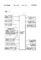
- FIG. 1is a block diagram showing a structure of a vehicle control system to which the present invention is applied;
- FIG. 2is a flowchart showing a portion of an obstacle warning operation of the vehicle control system
- FIG. 3is a flowchart showing a remaining portion of the obstacle warning operation of the vehicle control system
- FIG. 4is a flowchart showing a preceding obstacle recognition routine in FIG. 2;
- FIGS. 5A and 5Bare diagrams explaining creation of line segments in the preceding obstacle recognition routine
- FIG. 6is a diagram explaining definition of corresponding line segments in the preceding obstacle recognition routine
- FIGS. 7A and 7Bare diagrams explaining selection of the corresponding line segments in the preceding obstacle recognition routine
- FIG. 8is a flowchart showing a data update routine for updating an object label data in the preceding obstacle recognition routine
- FIG. 9is a flowchart showing an error-recognition judgment routine in the preceding obstacle recognition routine
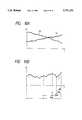
- FIGS. 10A and 10Bare graphs explaining how the error recognition is judged in the error-recognition judgment routine
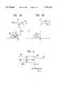
- FIG. 11is a diagram explaining calculation of a curvature radius of a road in the obstacle warning operation
- FIG. 12is a diagram explaining selection of points to be used for the calculation of the curvature radius
- FIG. 13is a diagram explaining exception to the calculation of the curvature radius
- FIG. 14is an illustration explaining an example of sharp curve judgment in the obstacle warning operation
- FIG. 15is a diagram explaining setting of a warning area in the obstacle warning operation
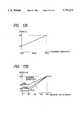
- FIGS. 16A, 16B and 16Care graphs each showing the relation between a constant for calculating a moving object warning distance and a warning sensitivity
- FIGS. 17A and 17Bare graphs each showing the relation between a constant for calculating a stationary object warning distance and a warning sensitivity
- FIG. 18is an illustration explaining an example of a prior art problem.
- FIG. 19is a block diagram of an exemplary structure of the present invention.
- FIG. 1is a block diagram showing a structure of a vehicle control system 1 to which the present invention is applied.
- the vehicle control system 1includes a distance/angle measuring device 3 serving as obstacle detecting means.
- the vehicle control system 1executes either or both of control processes in response to a setting position of a mode switch, not shown, one is a collision avoiding process in which the vehicle control system 1 detects a preceding vehicle ahead of a subject vehicle using the distance/angle measuring device 3 and generates an alarm sound when the preceding vehicle enters a given warning area in a forward direction of the subject vehicle, and the other is traveling control process in which the vehicle control system 1 controls the speed of the subject vehicle to hold the distance between the preceding vehicle and the subject vehicle at a predetermined value.
- a detection signal output from the distance/angle measuring device 3is supplied to an electronic control circuit 5.
- the electronic control circuit 5recognizes a preceding vehicle ahead of the subject vehicle in response to the detection signal output from the distance/angle measuring device 3. Further, the electronic control circuit 5 outputs a drive signal to a distance indicator 7 so that a inter-vehicle distance between the subject vehicle and the preceding vehicle will be indicated.
- the electronic control circuit 5outputs a drive signal to an alarm sound generator 9 serving as warning means so that an alarm sound will be generated by the alarm sound generator 9.
- An alarm volume setting device 11 and an alarm sensitivity setting device 13are connected to the electronic control circuit 5 so that the alarm volume and the alarm sensitivity will be adjusted by the electronic control circuit 5.
- the electronic control circuit 5serves to adjust the speed of the subject vehicle. To this end, the electronic control circuit 5 outputs drive signals to a throttle driver 15 for actuating a throttle valve, a brake driver 17 for actuate a brake and an automatic transmission controller 19 for adjusting an automatic transmission, respectively.
- the electronic control circuit 5is also connected to a vehicle speed sensor 21 for outputting a signal representing a speed of the subject vehicle, a brake switch 23 for outputting a signal representing an operational condition of the brake and a throttle position sensor 25 for outputting a signal representing the degree of opening of the throttle valve.
- the electronic control circuit 5thus receives data, which are needed to execute the collision avoiding process and the traveling control process, from the vehicle speed sensor 21, the brake switch 23 and the throttle position sensor 25. Further, the electronic circuit 5 is connected to a power supply switch 27 and a sensor abnormality indicator 29.
- the power supply switch 23serves to feed electric power from a power supply circuit, not shown, to the electronic control circuit 5 in response to operation of a key switch.
- the sensor abnormality indicator 29serves to indicate occurrence of a sensor abnormality among the sensors 21 to 25 in response to a drive signal output from the electronic control circuit 5.
- the distance/angle measuring device 3includes a transmitting/receiving section 31 and a distance/angle calculating section 33.
- the transmitting/receiving section 31emits pulses of a laser light beam at each given angle, for example, 0.5 degree, to scan a given angular range in a forward direction of the subject vehicle, and detects a reflected light beam from an object ahead of the subject vehicle.
- the distance/angle calculation section 33calculates a distance to and an angle (direction) of the preceding object ahead of the subject vehicle on the basis of time after the transmitting/receiving section 31 emitted the laser light beam until capturing the reflected light beam.
- Such a distance/angle measuring deviceis well known to those skilled persons in the art and the detailed description thereof will be omitted.
- the distance/angle measuring device 3may use an electric wave, such as a microwave or an ultrasonic wave, instead of laser light. Further, the distance/angle measuring device 3 may adopt a mono-pulsed system instead of the scan type system, in which the transmitting/receiving section 31 has two or more receivers and the distance/angle calculating section 33 calculates a distance to and an angle of an obstacle ahead of the subject vehicle on the basis of differences in strength and phase (time) between received signals.
- an electric wavesuch as a microwave or an ultrasonic wave
- the distance/angle calculating section 33After calculating the distance to and the angle of the obstacle, the distance/angle calculating section 33 inputs the results of calculation (hereinbelow, referred to as one-dimensional distance data) to the electronic control circuit 5. During execution of the collision avoiding process, the electronic control circuit 5 issues an alarm in response to the input of the one-dimensional distance data in the following manner.
- FIGS. 2 and 3show a flowchart of the main routines of an obstacle warning program executed by the electronic control circuit 5. The electronic control circuit 5 repeats the program every 128 ms.
- the programhas a first step 101.
- the step 101receives the one-dimensional distance data from the distance/angle calculating section 33, and transforms the received data in a given manner for recognizing or determining the position of the obstacle in orthogonal coordinates. Since the distance/angle measuring device 3 emits pulses of the laser light beam at each given angle, for example, 0.5 degree, to scan a given angular range, an obstacle or obstacles are recognized as discrete points, as exemplified by points P1 to P6 in FIG. 5A.
- a step 102 following the step 101executes a preceding obstacle recognition routine for recognizing an obstacle ahead of the subject vehicle as an object label.
- FIG. 4is a flowchart showing details of the preceding obstacle recognition routine corresponding to the step 102.
- a first step 103unites adjacent points among the points provided by the step 101 and recognizes each adjacent-point set as a line segment having a length only along the width direction of the subject vehicle.
- the "adjacent" points to form a line segmentare generally defined on the basis of given conditions.
- points spaced with each other by a given angular interval along an X-axis direction (the width direction of the subject vehicle) equal to or less than the emission interval of the laser light beam and by a given distance along a Y-axis direction (the longitudinal direction of the subject vehicle) less than 0.3 mare defined as adjacent points.
- the points P1 and P2are spaced from each other by an angular interval ⁇ X12 along the X-axis direction equal to or less than the emission interval of the laser light beam and by a distance ⁇ Y12 along the Y-axis direction less than 3.0 m.
- the step 103units points P1 and P2 into an adjacent-point set.
- the points P3 and P4are spaced from each other by a distance ⁇ Y34 along the Y-axis direction more than 3.0 m, so that the step 103 does not unite points P3 and P4 into an adjacent-point set.
- the step 103thus recognizes sets of unitable points (points P1 to P3 and points 4 to 6) as line segments S1 and S2 having widths W1 and W2 (i.e., lengths along the width direction of the subject vehicle), respectively.
- the widthdenotes a distance between the left-hand end point and the right-hand end point of each line segment.
- each pointhas a width defined by the emission interval of the laser light beam.
- the Y position of each of the line segments S1 and S2is set to a mean of the Y positions of the points P1, P2 and P3 or the points P4, P5 and P6.
- the electronic control circuit 5defines each of the line segments S1 and S2 by parameters including its center position (X1, Y1) or (X2, Y2) and its width W1 or W2. Such defined line segments are used for calculations as described later.
- the step 103does not recognize it as a line segment.
- a step 104 following the step 103recognizes such a point set as a guardrail, and memorizes, as guardrail data, the coordinates of the left-hand point, the coordinates of the right-hand point and the coordinates of the mid-point between the left-hand end and the right-hand end (hereinbelow, referred to as the center coordinates or center position of the guardrail data).
- a step 105 following the step 104sets a variable "i" to 1.
- the programadvances to a step 107.
- the step 107determines whether an object label Bi is present or absent, where "i" denotes a natural number.
- the object label Bicorresponds to a model of an obstacle which is created for a set of line segments. Since the object label Bi is not created for the first time, the step 107 determines that the object label Bi is absent.
- the programadvances to a step 111.
- the step 111determines whether or not there is at least one line segment to which an object label Bi has not yet been given. As previously described, no object label Bi is created for the first time.
- the programadvances from the step 111 to the step 113.
- Every object label Bjhas the following data pieces: a data piece representing the current coordinates (X, Y) of the center of the related line segment, a data piece representing the width W of the related line segment, a data piece representing the speed VX of the related line segment relative to the subject vehicle along the X-axis direction, a data piece representing the speed VY of the related line segment relative to the subject vehicle along the Y-axis direction, data pieces representing the 16 previous coordinates (X, Y) of the center of the related line segment, and a data piece representing a condition flag Fj.
- these data piecesare set as follows.
- the current center coordinates (X, Y) and the width Ware directly used as the center position and the width of a related line segment.
- the other data piecesare set as follows.
- the relative speed VXis set to zero.
- the relative speed VYis set to a speed which multiplies the speed of the subject vehicle by -1/2.
- the data pieces representing the 16 previous center coordinates (X, Y)are made vacant or empty.
- the condition flag Fjis set to "0".
- the condition flag Fjindicates which of an undecided state, a recognition state, and an extrapolation state the related object label Bj is in.
- the condition flag Fjis set to any one of "0", "1" and "2" according to the state.
- the condition flag Fjis set to "0" indicating that the object label Bj is in the undecided state. The definition of every state will be described later.
- the programadvances to a step 121.
- the step 121detects a line segment corresponding to the object label Bi.
- the definition of a line segment corresponding to the object label Biwill be described below. It is assumed that, as shown in FIG. 6, the position represented by the object label Bi moves from the previous position Bi(n-1) to a position (an estimated position) Bi(n) at a relative speed (VX, VY) where the position Bi(n-1) is provided in the last execution cycle of the program. After the calculation of the estimated position Bi(n), an estimated moving area BB is set around the estimated position Bi(n).
- the estimated moving area BBhas a given dimension ⁇ X along the X-axis direction and a given dimension ⁇ Y along the Y-axis direction.
- a line segment SSa at least partially in the estimated moving range Bbis defined as corresponding to the object label Bi, whereas a line segment SSb fully outside the estimated moving range BB is defined as not corresponding to the object label Bi.
- the given dimensions ⁇ X and ⁇ Yare set as follows.
- the given dimension ⁇ Xis set to 2.5 m while the given dimension ⁇ Y is set to 5.0 m.
- the given dimension ⁇ Xis set to 2.0 m while the given dimension ⁇ Y is set to 4.0 m.
- the given dimension ⁇ Xis set to 1.5 m while the given dimension ⁇ Y is set to 3.0 m.
- the step 121selects one of the line segments as corresponding to the object label Bi in a manner described below.
- FIG. 7Ais a diagram explaining how to select one of the line segments from N line segments at least partially in the estimated moving range BB.
- Numbers SS1, SS2, . . . , SSNare sequentially assigned to the N line segments in the order of the positions of the line segments in the direction from the left to the right. Then, five line segments SS1, SS1+INT(N+1/4), SSINT(N+1/2), SSN-INT(N+1/4), and SSN are selected from among the N line segments SS1, SS2,. . . . , SSN.
- INT(N+1/4)means INT ⁇ (N+1)/4 ⁇ .
- the line segments SS1, SS3, SS5, SS8 and SS10are selected.
- six candidates K1 to K6are created on the basis of the five selected line segments.
- the candidate K1is composed of only the line segment SS1.
- the candidate K2is composed of the line segments SS1+INT(N+1/4) to SSN-INT(N+1/4).
- the candidate K3is composed of only the line segment SSN.
- the candidate K4is composed of the line segments SS1 to SSINT(N+1/2).
- the candidate K5is composed of the line segments SSINT(N+1/2) to SSN.
- the candidate K6is composed of all the line segments SS1 to SSN.
- the line segments SS in each of the candidates K1 to K6are united as follows. At first, there is provided a new line segment having a width which extends between the left-hand end point and the right-hand end point of the combination of the line segments related to the candidates K1 to K6.
- the Y coordinate of the center of the new line segmentis equal to the mean or average value which results from weighting the Y coordinates of the line segments SS using the widths of the line segments SS as weighting factors.
- the center coordinates and the width of the new line segmentare compared with the center coordinates and the width of the object label Bi at the estimated position Bi(n), and hence an X-direction difference ⁇ X, a Y-direction difference ⁇ Y, and a width difference ⁇ W therebetween are evaluated by referring to the following performance index:
- the other line segments at least partially in the estimated moving range BBare regarded as not corresponding to the object label Bi.
- the above-indicated processing by the step 121makes it possible to accurately judge whether or not a line segment currently recognized by the step 103 is the same as a previously-recognized line segment.
- the number of line segments at least partially in the estimated moving range BBis between 2 and 4
- duplicate use of line segmentsis permitted in the five line segments SS1 to SSN so that six candidates can be created as well.
- the candidate K2is composed of only the line segment SS2.
- the candidate K4is composed of the line segments SS1 and SS2.
- the candidate K5is composed of the line segments SS2 and SS3.
- Steps 123 and 124 following the step 121execute update of the object label Bi and judgment of error recognition, respectively. Then, after the variable "i" is incremented in a step 125, the program returns to the step 107.
- FIG. 8is a flowchart showing an object-label data update routine for updating the object label Bi.
- This routinehas a first step 201 which follows the step 121 in FIG. 4.
- the step 201determines whether or not the preceding step 121 has detected the line segment corresponding to the object label Bi. In the case where the line segment corresponding to the object label Bi has been detected, i.e., in the case where a YES answer is obtained in the step 201, the object label Bi is considered to be in the recognition state.
- the programadvances from the step 201 to a step 203.
- the step 203sets the condition flag Fi to "1".
- a step 205 following the step 203resets a value Cni to "0".
- the value Cnidenotes a counter which serves to count the number of times the line segment corresponding to the object label Bi has not been detected by the step 121.
- a step 207 following the step 205increments a value Cai by one.
- the value Caidenotes a counter which serves to count the number of times the line segment corresponding to the object label Bi has been detected by the step 121.
- a step 209 following the step 207updates the data in the object label Bi in response to the data representing the line segment corresponding to the object label Bi. After the step 209, the program returns to the main routine.
- the line segment corresponding to the object label Biincludes a data piece representing the center coordinates and a data piece representing the width.
- the data piece representing the center coordinatesis denoted by (Xs, Ys) while the data piece representing the width is denoted by Ws. Therefore, new center coordinates and width represented by the object label Bi are set equal to the center coordinates (Xs, Ys) and the width Ws, respectively.
- the programadvances from the step 201 to a step 211.
- the step 211determines whether or not the condition flag Fi in the object label Bi is "2". In other words, the step 211 determines whether or not the object label Bi is in the extrapolation state. If the program advances to the step 211 for the first time, the condition flag Fi in the object label Bi is "0" or "1", so that the step 211 determines that the condition flag Fi in the object label Bi is not "2". After the step 211, the program sequentially advances to a step 213.
- the step 213determines whether or not the counter value Cai is 6 or more. In the case the counter value Cai is smaller than "6", i.e., in the case a No answer is obtained in the step 213, the program advances from the step 213 to a step 215. The step 215 erases all the data pieces related to the object label Bi. After the step 215, the program returns to the main routine. While the line segment corresponding to the object label Bi remains successively detected, the sequence of the steps 201 to 209 are periodically executed, so that the counter Cai continues to be incremented by the step 207.
- the programadvances from the step 213 to a step 221.
- the step 221regards the object label Bi as being in the extrapolation state, and sets the condition flag Fi in the object label Bi to "2".
- the programadvances to a step 225.
- the step 225increments the counter value Cni by one.
- a step 227 following the step 225determines whether or not the counter value Cni is 5 or more. When the counter value Cni is smaller than "5", the step 227 goes to NO.
- a step 229 following the step 227updates the data in the object label Bi in response to calculated values. Specifically, the step 229 calculates new center coordinates (X, Y) represented by the object label Bi on the assumption that the previously-indicated relative speeds (VX, VY) and the previously-indicated width W are unchanged.
- the step 221sets the condition flag Fi in the object label Bi to "2" representing the extrapolation state. Then, the step 229 updates the data in the object label Bi in response to the calculated values.
- the programdirectly advances from the step 221 to the step 225, so that the counter Cni continues to be incremented by the step 225.
- the programadvances from the step 227 to the step 215.
- the step 215erases all the data related to the object label Bi. Therefore, even when an obstacle (corresponding to the object label Bi) disappears in an interval corresponding to less than five execution cycles, if it appears again at the step 201 (the answer to the step 201 becomes YES) and continues to be detected during six or more execution cycles of this program portion, the obstacle is regarded as corresponding to the same object label Bi. It is thus possible to continue to detect such an obstacle.
- FIG. 9is a flowchart showing an error-recognition judgment routine.
- This routinehas a first step 301 which follows the step 124 in FIG. 4.
- the step 301set a variable "j" to 1.
- the programadvances to a step 303.
- the step 303calculates a relative acceleration ⁇ j of the object label Bi by referring to the following equation: ##EQU2## where "Ys" denotes a Y coordinate of the current object label Bi, "Ys-j" denotes a Y coordinate of the object label Bi detected j times before, and ⁇ t denotes one cycle of detection of the object label Bi, for example, 128 ms.
- the relative accelerationis set to "0".
- a step 307 following the step 303determines whether or not an absolute value of the calculated relative acceleration ⁇ j is equal to or less than " ⁇ 0+ ⁇ n/j 2 ".
- “ ⁇ 0" and “an”are given constants respectively.
- “ ⁇ 0”is set equal to 10 m/s 2
- " ⁇ n”is set equal to 120 m/s 2 .
- the programadvances to a step 309.
- the step 309sets "j" to a numerical value which is multiplied by 2.
- the programadvances to a step 311.
- the step 311determines whether or not "j" is eight or less. When “j" is equal to eight or less, i.e., a YES answer is obtained in the step 311, the program returns to the step 303. Then, the sequence of steps 303 to 311 are repeatedly executed. In four execution cycles of this program portion, "j" becomes 16 in excess of 8, so that a NO answer is obtained in the step 311. After that, the program returns to the main routine.
- the programadvances from the step 307 to a step 313.
- the step 313erases all the data related to the object label Bi.
- the programreturns to the main routine. It is thus possible to erase the data related to a negligible road-side thing erroneously recognized as an obstacle corresponding to the object label Bi. Such data related to the negligible road-side thing are erased as follows.
- a curve 91represents a case where the object label Bi corresponds to a preceding vehicle which gradually goes away from the subject vehicle while a curve 93 represents a case where the object label Bi corresponds to a preceding vehicle which is approaching the subject vehicle.
- the absolute value of the relative acceleration ⁇ jis equal to or less than ⁇ 0+ ⁇ n/j 2 . The condition provided by the step 307 is thus satisfied.
- the Y coordinate represented by the object Bichanges with time irregularly or unpredictably.
- the speed of the subject vehiclebecomes substantially equal to a numerical value which is obtained by dividing a scanning cycle of the transmitting/receiving section 31 into the given space between the reflectors
- the reflectorsare erroneously recognized as if it were an object.
- the Y coordinate represented by the object label Bitends to change with time irregularly as shown in FIG. 10B.
- the absolute value of the relative acceleration ⁇ jmay exceed ⁇ 0+ ⁇ n/j 2 . If such a condition is established, i.e., when a NO answer is obtained in the step 307, the object label Bi is regarded as corresponding to an erroneously-recognized object such as a thing on the road shoulder, so that the step 313 erases all the data related the object label Bi but the center coordinates which are memorized as data pieces representing erroneously-recognized object.
- the object label Bicorresponding to the number "i" incremented last by the step 125 is absent. Therefore, a NO answer is obtained in the step 107 and the program advances from the step 107 to the step 111.
- the programadvances to the step 113.
- the step 113sequentially creates new object labels Bj with respect to the line segments to which corresponding object labels have not yet been given.
- the new object labels Bjare created in the order of from the line segment having the smallest number "j".
- the current execution cycle of the program portionends and the program returns to the main routine.
- the current execution cycle of the program portionends without creating the new object labels Bj.
- a step 403 following the step 102executes a correction-time counter setting routine for setting a correction time counter.
- the correction time counteris used as a condition provided by a step 423.
- the correction-time counter setting routineis executed as follow.
- a curvature radius R of a curved road on which the subject vehicle is travelingis calculated on the basis of data representing the object label Bi.
- it is determined whether the object label Bi corresponds to a stationary object or a moving object on the basis of the speed of the subject vehicle and the speed of the object label Bi relative to the subject vehicleby using a well-known processing method.
- a plurality of stationary objectsare detected, a plurality of curvature radii R are calculated for the respective stationary objects, and an absolute value of the minimum curvature radius is selected from among the calculated curvature radii R.
- the curvature radiusis defined in the following three steps (1) to (3).
- FIG. 11it is assumed that five loci B0 to B4 of the identical stationary object recognized by the step 101 are obtained at respective regular time intervals.
- (Xj, Yj)denotes each of the coordinates of the left ends, the centers, and the right ends, respectively, corresponding to a locus Bj.
- coordinates (Xt, Yt) and (Xb, Yb) of both ends of one of the line segments L, C and R provided by (b) in the step (1)are determined from the five points selected by (d) in the step (1).
- the curvature radius Ris determined by solving the following simultaneous equations using the coordinates (Xt, Yt) and (Xb, Yb) provided by the step (2).
- An equation of circleis defined by an arc extending through the two points (Xt, Yt) and (Xb, Yb), intersecting at the point (X, 0) the X-axis passing through the center of the subject vehicle.
- the equation of circlealso approximates a parabola under the condition that
- the following setting conditionsmay add a value to the correction time counter.
- the correction time counteris configured to reduce its value to 0 sec. gradually with time during the execution cycle of the electronic control circuit 5.
- the lateral Gdenotes a gravity accelerated in the width direction of the subject vehicle, which is given by solving the following equation.
- FIG. 14illustrates a case where the distance/angle measuring device 3 is detecting a reflected light beam from a guardrail 97 while a subject vehicle 95 travels a curved road 96.
- the guardrail data representing the guardrail 97is parallel to the Y coordinate of the subject vehicle 95, and the center coordinates Pa of the guardrail data does not fall into a range 99 of the above condition (
- the guardrail datais not parallel to the Y coordinate of the subject vehicle 95, but the center coordinates Pb of the guardrail data has not yet fall into the range 99 although comes close to the range.
- the center coordinates Pcfall into the range 99.
- the step (3)thus detects a sharp curve and adds the correction time counter value.
- the programAfter setting a value of the correction time counter on the basis of any one of the above conditions (1) to (5), the program advances to a step 405.
- the step 405sets a variable "i" to 0.
- a step 407 following the step 405increments the variable "i".
- the programadvances to a step 409.
- the step 409determines whether or not there is possibility of collision between the subject vehicle and an obstacle represented by the current object label Bi (collision judgment) in a manner described below.
- a warning area WAIis set by using a curvature radius R calculated from the object label Bi by the step 403. Even when the object label Bi corresponds to a moving object, the curvature radius R representing the path of the object label Bi is calculated in the same manner so that the warning area WAI can be set. As shown in FIG. 15, the warning area WAI is set as follows. When the curvature radius R provided by the step 403 is represented by an arc L1, a concentric arc L2 is defined such as passing through the center of the subject vehicle along the longitudinal direction.
- the starting and ending locations in the Y-axis direction of the warning area WAIare determined by the points (Xt, Yt) and (Xb, Yb) of both ends of the guardrail data, while the lateral range of the warning area WAI are set at both sides of the arc L2 by a width of ⁇ 1 m.
- the warning area WAIis made to approximate to a parallelogram. Four vertices of the parallelogram are determined by parallelogram approximation according to the following equation. ##EQU3##
- the warning area WAI provided such aboveis used for the collision judgment.
- the step 409determines whether or not there is possibility of collision between the subject vehicle and the obstacle represented by the current object label Bi by determining whether or not the object label Bi exists within the warning area WAI for a given time interval.
- a step 411 following the step 409refers to the determination provided by the step 409.
- the programadvances to a step 413.
- the step 413determines whether the object label Bi corresponds to a stationary object or a moving object on the basis of the speed of the subject vehicle and the speed of the object label Bi relative to the subject vehicle.
- the programadvances to a step 415.
- the step 415calculates a warning distance to the moving object by solving the following equation:
- VRdenotes a speed (m/s) of the subject vehicle
- VRRdenotes a relative speed (m/s) of the moving object under the condition that a direction away from the subject vehicle is positive
- OFFSETdenotes a constant, for example, 3.0 m
- TIMEK"TIMEN, and "GR” denote constants determined by the warning sensitivity (see FIGS. 16A, 16B and 16C).
- the programadvances to a step 421.
- the step 421calculates a warning distance to the moving object by solving the following equation:
- VRRdenotes a relative speed (m/s) of the stationary object under the condition that a direction away from the subject vehicle is positive
- OFFSETdenotes a constant, for example, 3.0 m
- TIMEN and GRdenote constants determined by the warning sensitivity (see FIG. 17).
- the warning distanceis set to a distance enough to brake down and stop the subject vehicle on this side of the obstacle.
- a step 423 following the step 421determines whether or not the value of the correction time counter is larger than 0.
- the programjumps to a step 417.
- the programadvances to the step 417 after correcting the warning distance in a step 425.
- the step 425calculates the warning distance by solving the following equation.
- the step 425determines whether or not the value of the warning distance calculated here is smaller than the warning distance provided by the step 421.
- the warning distanceis replaced by the value calculated in the step 425. Otherwise, the value provided by the step 421 is used as the warning distance. In both cases, the warning distance is to be set to a distance enough to brake down and stop the subject vehicle on this side of the object.
- the sequential step 417determines whether the object label Bi corresponds to a stationary object and the width W of the object label Bi does not correspond to the width of the subject vehicle (W ⁇ 1.0 m or W ⁇ 3.0 m). In the case where the object label Bi satisfies both conditions, the object label Bi is regarded as corresponding to a road-side thing. Therefore, the object label Bi is removed from the warning object data to be considered.
- the programadvances to a step 429.
- the step 429determines whether or not the object vehicle Bi exists within a range of the warning distance provided by the step 415, 421 or 425.
- the programadvances to a step 431.
- the step 431recognizes the object label Bi as a warning object. After the step 431, the program advances to a step 433.
- the step 417determines that the object label Bi satisfies the above conditions (and goes to YES)
- the step 429determines that the object label Bi does not exist within the range of the warning distance (and goes to NO)
- the step 411determines, as previously described, that there is no possibility of collision with the object corresponding to the object label Bi (and goes to No), the object label Bi is not recognized as a warning object.
- the programjumps to the step 433.
- the step 433determines whether at least one undecided object label Bi is present or absent. In the case where at least one unjudged object label Bi is present, i.e., in the case where a YES answer is obtained in the step 433, the program returns to the step 407 and the program portion after the step 407 is repeated. In other words, the step 407 increments "i" by one. After the step 407, the sequence of the steps 409 to 431 are executed. When this program portion is executed for all the object labels Bi, i.e., when a NO answer is obtained in the step 433, the program advances to a step 435. The step 435 determines whether at least one object label Bi recognized as the warning object is present or absent.
- the programadvances to a step 437.
- the step 437executes a warning process by actuating the alarm sound generator 9 on the basis of the setting of the alarm volume setting device 11. After the step 437, the current execution cycle of the program portion ends.
- the programadvances to a step 441.
- the step 441determines whether or not the alarm remains generated.
- the programadvances to a step 443.
- the step 443stops the alarm and the current execution cycle of the program portion ends.
- no alarmi.e., when a NO answer is obtained in the step 441
- the current execution cycle of the program portionimmediately ends.
- the step 403sets the correction time counter on the basis of the curved state of the road, and steps 423 and 425 corrects the warning distance in response to the value of the correction time counter.
- the vehicle control system 1issues an alarm in the step 437. It is thus possible to avoid an accident such as collision with or clash into a preceding vehicle.
- the vehicle control system 1Since the step 403 detects the curved state of the road on the basis of the curvature radius (conditions (1) and (2)), the position in which a guardrail is detected (condition (3)), the position in which an erroneously-recognized objected is detected (condition (4)), and the number of obstacles recognized as object labels Bi (condition (5)), the vehicle control system 1 enables remarkably accurate detection of the curved state, and hence accurate generation of the alarm, thereby avoiding a false alarm properly.
- the curved stateis calculated on the basis of the distance to and angle of the obstacle detected by the distance/angle measuring device 3, so that means or device for detecting a steering angle or the like does not need to be provided in the system, thereby simplifying the system structure.
- the vehicle control system 1is able to correct the warning distance to the stationary object which is susceptible to the curved state, so that the alarm can be generated more accurately. Furthermore, the vehicle control system 1 is able to remove road-side things from warning objects on the basis of the conditions that the object label Bi corresponds to a stationary object and the width W of the object label Bi does not correspond to the width of the subject vehicle (step 417), so that the alarm can be generated still more accurately, thereby avoiding a false alarm more properly.
- the condition (3) for detecting the curved statecan be also used in a case where only a guardrail is present on the road shoulder without a reflector.
- the other conditionscan be used to a road-side thing even if there is no guardrail on the road shoulder. Therefore, the curved state can be detected properly as long as either the guardrail or the road-side thing such as the reflector is present on the road shoulder. It is thus possible to avoid a false alarm irrespective of the road type.
- the step 104corresponds to the guardrail detecting means
- the step 403corresponds to the curved state detecting means and the curvature radius calculating means
- the steps 423 and 425correspond to the warning condition correcting means
- the step 303corresponds to the acceleration calculating means
- the step 313corresponds to the erroneously-recognized object detecting means, respectively.
- the present inventionis not limited by the embodiment, and other embodiments or modification can be embodied without departing from the scope of the invention as set forth in the appended claims.
- the detection of the curved statecan be executed by other type of means or on the basis of conditions other than the conditions (1) to (5) provided by the embodiment. Otherwise, part or parts of the conditions (1) to (5) may be used to detect the curved state.
- the embodimentis configured to correct the warning distance on the basis of whether or not the counter value is greater than 0, the correction may be performed such that the warning distance is gradually increased or decreased according to the counter value.
- the warning distancemay be corrected without the counter value, for example, by setting up a flag when each of the conditions (1) to (5) is satisfied.
- the embodimentis configured to correct the warning distance as a warning condition, other warning conditions may be corrected, such as the size of the object label corresponding to the warning object, or the approaching speed of the object label.
Landscapes
- Engineering & Computer Science (AREA)
- Chemical & Material Sciences (AREA)
- Physics & Mathematics (AREA)
- Transportation (AREA)
- Mechanical Engineering (AREA)
- Combustion & Propulsion (AREA)
- Radar, Positioning & Navigation (AREA)
- Remote Sensing (AREA)
- General Physics & Mathematics (AREA)
- Electromagnetism (AREA)
- Automation & Control Theory (AREA)
- Computer Networks & Wireless Communication (AREA)
- Chemical Kinetics & Catalysis (AREA)
- Materials Engineering (AREA)
- Spectroscopy & Molecular Physics (AREA)
- Traffic Control Systems (AREA)
- Control Of Driving Devices And Active Controlling Of Vehicle (AREA)
- Radar Systems Or Details Thereof (AREA)
Abstract
Description
INT(11/4)=INT(2.75)=2
INT(11/2)=INT(5.5)=5
α ΔX+β Δ Y+γ Δ W,
St=Σ{(aYj+b-Yj)·(aYj+b-Xj)},Xt-Xz=Yt·Yt/2R
Xb-Xz=Yb·Yb/2R
|x|<<|Y| and |x|<<|R|.
a=V.sup.2 /R (m/s.sup.2)
OFFSET+VR×TIMEK-VRR×TIMEN+VRR.sup.2 /2GR,
OFFSET-VRR×TIMEN+VRR.sup.2 /2GR,
ma×{(speed of subject vehicle km/h!×0.7) m!, 30 m!}Claims (8)
Applications Claiming Priority (2)
| Application Number | Priority Date | Filing Date | Title |
|---|---|---|---|
| JP7-343624 | 1995-12-28 | ||
| JP34362495AJP3656301B2 (en) | 1995-12-28 | 1995-12-28 | Obstacle warning device for vehicles |
Publications (1)
| Publication Number | Publication Date |
|---|---|
| US5751211Atrue US5751211A (en) | 1998-05-12 |
Family
ID=18362972
Family Applications (1)
| Application Number | Title | Priority Date | Filing Date |
|---|---|---|---|
| US08/777,196Expired - LifetimeUS5751211A (en) | 1995-12-28 | 1996-12-27 | Obstacle warning system for a vehicle |
Country Status (3)
| Country | Link |
|---|---|
| US (1) | US5751211A (en) |
| JP (1) | JP3656301B2 (en) |
| DE (1) | DE19654691B4 (en) |
Cited By (127)
| Publication number | Priority date | Publication date | Assignee | Title |
|---|---|---|---|---|
| US5917443A (en)* | 1997-07-15 | 1999-06-29 | Mitsubishi Denki Kabushiki Kaisha | Vehicle-mounted radar apparatus |
| US5939976A (en)* | 1997-07-31 | 1999-08-17 | Toyota Jidosha Kabushiki Kaisha, Hino Jidosha Kogyo Kabushiki Kaisha, Aisin Seiki Kabushiki Kaisha, And Denso Corporation | Intersection warning system |
| US6122040A (en)* | 1997-11-06 | 2000-09-19 | Omron Corporation | System and method of detecting deviation of an axis and adjusting the axis of a range finder |
| EP1020736A3 (en)* | 1999-01-13 | 2001-04-11 | Honda Giken Kogyo Kabushiki Kaisha | Radar apparatus |
| US6223117B1 (en)* | 1997-05-27 | 2001-04-24 | General Motors Corporation | Cut-in management for an adaptive cruise control system |
| US6265990B1 (en) | 1998-07-17 | 2001-07-24 | Denso Corporation | Apparatus and method for controlling a distance between two traveling vehicles and a recording medium for storing the control method |
| US6269308B1 (en)* | 1998-08-20 | 2001-07-31 | Honda Giken Kogyo Kabushiki Kaisha | Safety running system for vehicle |
| FR2807195A1 (en)* | 2000-03-28 | 2001-10-05 | Renault | DEVICE FOR AIDING THE DRIVING OF A MOTOR VEHICLE WHEN CHANGING THE ROUTE OF TRAFFIC OF THE VEHICLE |
| US6327530B1 (en) | 1998-07-13 | 2001-12-04 | Denso Corporation | Apparatus and method for controlling a distance between two traveling vehicles and a recording medium for storing the control method |
| US6418370B1 (en) | 1998-08-04 | 2002-07-09 | Denso Corporation | Apparatus and method for controlling a target distance and a warning distance between traveling vehicles and a recording medium for storing the control method |
| US20020105418A1 (en)* | 2000-12-22 | 2002-08-08 | Masayuki Yurimoto | Vehicular alarm system and apparatus |
| WO2002030792A3 (en)* | 2000-10-10 | 2002-09-06 | Dbt America Inc | Automated continuous haulage system |
| US20020157887A1 (en)* | 2001-04-27 | 2002-10-31 | Ryoichi Sugawara | Optical object detection apparatus designed to monitor front and lateral zones of vehicle |
| US6498972B1 (en) | 2002-02-13 | 2002-12-24 | Ford Global Technologies, Inc. | Method for operating a pre-crash sensing system in a vehicle having a countermeasure system |
| US6519519B1 (en) | 2002-02-01 | 2003-02-11 | Ford Global Technologies, Inc. | Passive countermeasure methods |
| FR2828741A1 (en)* | 2001-08-14 | 2003-02-21 | Denso Corp | OBSTACLE DETECTION DEVICE AND RELATED COMMUNICATION DEVICE |
| US6542111B1 (en)* | 2001-08-13 | 2003-04-01 | Yazaki North America, Inc. | Path prediction for vehicular collision warning system |
| US6553283B2 (en)* | 2000-03-09 | 2003-04-22 | Denso Corporation | Method and apparatus for recognizing shape of road |
| US20030076981A1 (en)* | 2001-10-18 | 2003-04-24 | Smith Gregory Hugh | Method for operating a pre-crash sensing system in a vehicle having a counter-measure system |
| US20030099400A1 (en)* | 2001-11-26 | 2003-05-29 | Takahiro Ishikawa | Obstacle monitoring device using one-dimensional signal |
| US20030139864A1 (en)* | 2002-01-24 | 2003-07-24 | Ford Global Technologies, Inc. | Post collision restraints control module |
| WO2003000522A3 (en)* | 2001-06-26 | 2003-08-21 | Medius Inc | Method and apparatus for managing audio devices |
| US6624782B2 (en)* | 2000-02-28 | 2003-09-23 | Veridian Engineering, Inc. | System and method for avoiding accidents in intersections |
| US6721659B2 (en) | 2002-02-01 | 2004-04-13 | Ford Global Technologies, Llc | Collision warning and safety countermeasure system |
| US20040111200A1 (en)* | 2001-11-29 | 2004-06-10 | Rao Manoharprasad K. | Vehicle sensing based pre-crash threat assessment system |
| US6775605B2 (en) | 2001-11-29 | 2004-08-10 | Ford Global Technologies, Llc | Remote sensing based pre-crash threat assessment system |
| US6831572B2 (en) | 2002-01-29 | 2004-12-14 | Ford Global Technologies, Llc | Rear collision warning system |
| US20050105773A1 (en)* | 2003-09-24 | 2005-05-19 | Mitsuru Saito | Automated estimation of average stopped delay at signalized intersections |
| US20050179580A1 (en)* | 2002-07-15 | 2005-08-18 | Shan Cong | Road curvature estimation and automotive target state estimation system |
| US20050192769A1 (en)* | 2004-02-20 | 2005-09-01 | Von Reyher Alexander | Process for evaluating a signal from a motor vehicle environment sensor |
| EP1571638A1 (en)* | 2004-03-05 | 2005-09-07 | Robert Bosch Gmbh | Method for distance warning for a vehicle and distance warning unit |
| US20050228580A1 (en)* | 2002-04-27 | 2005-10-13 | Hermann Winner | Method and device for predicting the course of motor vehicles |
| US7009500B2 (en) | 2002-02-13 | 2006-03-07 | Ford Global Technologies, Llc | Method for operating a pre-crash sensing system in a vehicle having a countermeasure system using stereo cameras |
| US20060220951A1 (en)* | 2005-04-04 | 2006-10-05 | Raytheon Company | System and method for coherently combining a plurality of radars |
| US20070008211A1 (en)* | 2005-03-31 | 2007-01-11 | Denso It Laboratory, Inc. | Vehicle mounted radar apparatus |
| RU2304078C2 (en)* | 2001-10-09 | 2007-08-10 | Дбт Америка Инк. | Automated continuous haulage system |
| US20070277175A1 (en)* | 2002-04-24 | 2007-11-29 | Medius, Inc. | Method for multi-tasking multiple java virtual machines in a secure environment |
| US20080183419A1 (en)* | 2002-07-15 | 2008-07-31 | Automotive Systems Laboratory, Inc. | Road curvature estimation system |
| US20080218340A1 (en)* | 2007-03-07 | 2008-09-11 | Gregory Royer | System and method for improving infrared detector performance in dual detector system |
| US20080218339A1 (en)* | 2007-03-07 | 2008-09-11 | Gregory Royer | System and method for improving microwave detector performance using ranging microwave function |
| US20080218341A1 (en)* | 2007-03-07 | 2008-09-11 | Gregory Royer | System and method for implementing ranging microwave for detector range reduction |
| US7446650B2 (en) | 1998-01-07 | 2008-11-04 | Donnelly Corporation | Accessory system suitable for use in a vehicle |
| US20080291522A1 (en)* | 1994-05-05 | 2008-11-27 | Donnelly Corporation | Exterior reflective mirror element for a vehicle rearview mirror assembly |
| US7474963B2 (en) | 2000-03-02 | 2009-01-06 | Donnelly Corporation | Navigational mirror system for a vehicle |
| US20090045972A1 (en)* | 2001-04-24 | 2009-02-19 | Medius, Inc. | Method and apparatus for dynamic configuration of multiprocessor system |
| US7494231B2 (en) | 1994-05-05 | 2009-02-24 | Donnelly Corporation | Vehicular signal mirror |
| US7586666B2 (en) | 2002-09-20 | 2009-09-08 | Donnelly Corp. | Interior rearview mirror system for a vehicle |
| US7619508B2 (en) | 2001-01-23 | 2009-11-17 | Donnelly Corporation | Video mirror system for a vehicle |
| US7667579B2 (en) | 1998-02-18 | 2010-02-23 | Donnelly Corporation | Interior mirror system |
| US7728721B2 (en) | 1998-01-07 | 2010-06-01 | Donnelly Corporation | Accessory system suitable for use in a vehicle |
| US7815326B2 (en) | 2002-06-06 | 2010-10-19 | Donnelly Corporation | Interior rearview mirror system |
| US7826123B2 (en) | 2002-09-20 | 2010-11-02 | Donnelly Corporation | Vehicular interior electrochromic rearview mirror assembly |
| US7832882B2 (en) | 2002-06-06 | 2010-11-16 | Donnelly Corporation | Information mirror system |
| US7855755B2 (en) | 2005-11-01 | 2010-12-21 | Donnelly Corporation | Interior rearview mirror assembly with display |
| US7864399B2 (en) | 2002-09-20 | 2011-01-04 | Donnelly Corporation | Reflective mirror assembly |
| US7888629B2 (en) | 1998-01-07 | 2011-02-15 | Donnelly Corporation | Vehicular accessory mounting system with a forwardly-viewing camera |
| US7898719B2 (en) | 2003-10-02 | 2011-03-01 | Donnelly Corporation | Rearview mirror assembly for vehicle |
| US7906756B2 (en) | 2002-05-03 | 2011-03-15 | Donnelly Corporation | Vehicle rearview mirror system |
| US7914188B2 (en) | 1997-08-25 | 2011-03-29 | Donnelly Corporation | Interior rearview mirror system for a vehicle |
| US7926960B2 (en) | 1999-11-24 | 2011-04-19 | Donnelly Corporation | Interior rearview mirror system for vehicle |
| US8001860B1 (en) | 2004-11-09 | 2011-08-23 | Eagle Harbor Holdings LLC | Method and apparatus for the alignment of multi-aperture systems |
| US8019505B2 (en) | 2003-10-14 | 2011-09-13 | Donnelly Corporation | Vehicle information display |
| US8049640B2 (en) | 2003-05-19 | 2011-11-01 | Donnelly Corporation | Mirror assembly for vehicle |
| US20110295548A1 (en)* | 2010-05-26 | 2011-12-01 | Mitsubishi Electric Corporation | Road configuration estimation apparatus, computer program, and road configuration estimation method |
| US8083386B2 (en) | 2001-01-23 | 2011-12-27 | Donnelly Corporation | Interior rearview mirror assembly with display device |
| US8154418B2 (en) | 2008-03-31 | 2012-04-10 | Magna Mirrors Of America, Inc. | Interior rearview mirror system |
| US8194133B2 (en) | 2000-03-02 | 2012-06-05 | Donnelly Corporation | Vehicular video mirror system |
| US20120154200A1 (en)* | 2010-12-17 | 2012-06-21 | Fujitsu Limited | Control apparatus, radar detection system, and radar detection method |
| US8288711B2 (en) | 1998-01-07 | 2012-10-16 | Donnelly Corporation | Interior rearview mirror system with forwardly-viewing camera and a control |
| US8294975B2 (en) | 1997-08-25 | 2012-10-23 | Donnelly Corporation | Automotive rearview mirror assembly |
| US8339526B2 (en) | 2006-03-09 | 2012-12-25 | Gentex Corporation | Vehicle rearview mirror assembly including a high intensity display |
| US20130030686A1 (en)* | 2010-04-05 | 2013-01-31 | Morotomi Kohei | Collision judgment apparatus for vehicle |
| US8369967B2 (en) | 1999-02-01 | 2013-02-05 | Hoffberg Steven M | Alarm system controller and a method for controlling an alarm system |
| US8417490B1 (en) | 2009-05-11 | 2013-04-09 | Eagle Harbor Holdings, Llc | System and method for the configuration of an automotive vehicle with modeled sensors |
| US8462204B2 (en) | 1995-05-22 | 2013-06-11 | Donnelly Corporation | Vehicular vision system |
| US8503062B2 (en) | 2005-05-16 | 2013-08-06 | Donnelly Corporation | Rearview mirror element assembly for vehicle |
| US8525703B2 (en) | 1998-04-08 | 2013-09-03 | Donnelly Corporation | Interior rearview mirror system |
| US8879139B2 (en) | 2012-04-24 | 2014-11-04 | Gentex Corporation | Display mirror assembly |
| US8886392B1 (en) | 2011-12-21 | 2014-11-11 | Intellectual Ventures Fund 79 Llc | Methods, devices, and mediums associated with managing vehicle maintenance activities |
| US8892495B2 (en) | 1991-12-23 | 2014-11-18 | Blanding Hovenweep, Llc | Adaptive pattern recognition based controller apparatus and method and human-interface therefore |
| US9019091B2 (en) | 1999-11-24 | 2015-04-28 | Donnelly Corporation | Interior rearview mirror system |
| CN104602982A (en)* | 2012-09-04 | 2015-05-06 | 丰田自动车株式会社 | Collision avoidance assistance device and collision avoidance assistance method |
| US20150353132A1 (en)* | 2013-01-28 | 2015-12-10 | Jaguar Land Rover Limited | Motor vehicle system and method |
| US9310805B2 (en) | 2012-05-02 | 2016-04-12 | Atlas Copco Rock Drills Ab | Method and system for maneuvering a mobile mining machine in a tunnel and a mobile mining machine |
| US9358924B1 (en) | 2009-05-08 | 2016-06-07 | Eagle Harbor Holdings, Llc | System and method for modeling advanced automotive safety systems |
| US9487144B2 (en) | 2008-10-16 | 2016-11-08 | Magna Mirrors Of America, Inc. | Interior mirror assembly with display |
| US9511715B2 (en) | 2014-01-31 | 2016-12-06 | Gentex Corporation | Backlighting assembly for display for reducing cross-hatching |
| US9575315B2 (en) | 2013-09-24 | 2017-02-21 | Gentex Corporation | Display mirror assembly |
| US9598018B2 (en) | 2013-03-15 | 2017-03-21 | Gentex Corporation | Display mirror assembly |
| USD783480S1 (en) | 2014-12-05 | 2017-04-11 | Gentex Corporation | Rearview device |
| US9694752B2 (en) | 2014-11-07 | 2017-07-04 | Gentex Corporation | Full display mirror actuator |
| US9694751B2 (en) | 2014-09-19 | 2017-07-04 | Gentex Corporation | Rearview assembly |
| WO2017120842A1 (en)* | 2016-01-14 | 2017-07-20 | 邓娟 | Alarm method and device for unduly close vehicle distances |
| WO2017120841A1 (en)* | 2016-01-14 | 2017-07-20 | 邓娟 | Information reminding method when warning according to vehicle distance and warning device |
| WO2017120840A1 (en)* | 2016-01-14 | 2017-07-20 | 邓娟 | Method and device for data collection when raising alarm |
| US9720278B2 (en) | 2015-01-22 | 2017-08-01 | Gentex Corporation | Low cost optical film stack |
| US9744907B2 (en) | 2014-12-29 | 2017-08-29 | Gentex Corporation | Vehicle vision system having adjustable displayed field of view |
| USD797627S1 (en) | 2015-10-30 | 2017-09-19 | Gentex Corporation | Rearview mirror device |
| USD798207S1 (en) | 2015-10-30 | 2017-09-26 | Gentex Corporation | Rearview mirror assembly |
| USD800618S1 (en) | 2015-11-02 | 2017-10-24 | Gentex Corporation | Toggle paddle for a rear view device |
| US9834146B2 (en) | 2014-04-01 | 2017-12-05 | Gentex Corporation | Automatic display mirror assembly |
| USD809984S1 (en) | 2016-12-07 | 2018-02-13 | Gentex Corporation | Rearview assembly |
| USD817238S1 (en) | 2016-04-29 | 2018-05-08 | Gentex Corporation | Rearview device |
| US9995854B2 (en) | 2015-04-20 | 2018-06-12 | Gentex Corporation | Rearview assembly with applique |
| US9994156B2 (en) | 2015-10-30 | 2018-06-12 | Gentex Corporation | Rearview device |
| US10025138B2 (en) | 2016-06-06 | 2018-07-17 | Gentex Corporation | Illuminating display with light gathering structure |
| US10071689B2 (en) | 2014-11-13 | 2018-09-11 | Gentex Corporation | Rearview mirror system with a display |
| US10112540B2 (en) | 2015-05-18 | 2018-10-30 | Gentex Corporation | Full display rearview device |
| US10131279B2 (en) | 2014-12-03 | 2018-11-20 | Gentex Corporation | Display mirror assembly with an RF shield bezel |
| CN108839615A (en)* | 2018-05-21 | 2018-11-20 | 浙江吉利汽车研究院有限公司 | A kind of driving warning method, device and electronic equipment |
| CN109263644A (en)* | 2018-09-28 | 2019-01-25 | 潍柴动力股份有限公司 | A kind of target identification method and device |
| USD845851S1 (en) | 2016-03-31 | 2019-04-16 | Gentex Corporation | Rearview device |
| US10298735B2 (en) | 2001-04-24 | 2019-05-21 | Northwater Intellectual Property Fund L.P. 2 | Method and apparatus for dynamic configuration of a multiprocessor health data system |
| CN109952518A (en)* | 2016-09-09 | 2019-06-28 | 克诺尔商用车制动系统有限公司 | Vehicle driver used for vehicles carries out the equipment of the warning of object and the vehicle with this equipment |
| USD854473S1 (en) | 2016-12-16 | 2019-07-23 | Gentex Corporation | Rearview assembly |
| US10361802B1 (en) | 1999-02-01 | 2019-07-23 | Blanding Hovenweep, Llc | Adaptive pattern recognition based control system and method |
| US10583832B2 (en) | 2017-05-02 | 2020-03-10 | Cnh Industrial America Llc | Obstacle detection system for a work vehicle |
| CN111186438A (en)* | 2020-01-16 | 2020-05-22 | 张殿英 | Filtering method for curve obstacle vehicle |
| US10685623B2 (en) | 2015-10-30 | 2020-06-16 | Gentex Corporation | Toggle paddle |
| US10705332B2 (en) | 2014-03-21 | 2020-07-07 | Gentex Corporation | Tri-modal display mirror assembly |
| US10735638B2 (en) | 2017-03-17 | 2020-08-04 | Gentex Corporation | Dual display reverse camera system |
| US11178353B2 (en) | 2015-06-22 | 2021-11-16 | Gentex Corporation | System and method for processing streamed video images to correct for flicker of amplitude-modulated lights |
| US20210380082A1 (en)* | 2020-06-04 | 2021-12-09 | Hyundai Mobis Co., Ltd. | System and method for controlling driving of vehicle |
| US20230008744A1 (en)* | 2021-07-07 | 2023-01-12 | Subaru Corporation | Driving assistance device for vehicle |
| US11567172B2 (en)* | 2016-03-24 | 2023-01-31 | Valeo Schalter Und Sensoren Gmbh | Method for capturing at least one object, device of a sensor apparatus, sensor apparatus and driver assistance system with at least one sensor apparatus |
| US11800050B2 (en) | 2016-12-30 | 2023-10-24 | Gentex Corporation | Full display mirror with on-demand spotter view |
| US11994272B2 (en) | 2021-08-20 | 2024-05-28 | Gentex Corporation | Lighting assembly and illumination system having a lighting assembly |
Families Citing this family (9)
| Publication number | Priority date | Publication date | Assignee | Title |
|---|---|---|---|---|
| JP3465591B2 (en)* | 1998-05-27 | 2003-11-10 | 三菱自動車工業株式会社 | Rear monitor system for vehicles |
| DE102009045286A1 (en) | 2009-10-02 | 2011-04-21 | Robert Bosch Gmbh | Method for imaging the environment of a vehicle |
| JP2011196943A (en)* | 2010-03-23 | 2011-10-06 | Denso Corp | Recognition device |
| JP5556317B2 (en)* | 2010-04-07 | 2014-07-23 | 株式会社デンソー | Object recognition device |
| JP2013036978A (en)* | 2011-07-12 | 2013-02-21 | Denso Corp | Target detection apparatus and wall determination method |
| JP2014071012A (en)* | 2012-09-28 | 2014-04-21 | Daimler Ag | Control object detection device and emergency automatic braking system |
| JP5979259B2 (en)* | 2015-01-20 | 2016-08-24 | トヨタ自動車株式会社 | Collision avoidance control device |
| JP6657673B2 (en)* | 2015-08-28 | 2020-03-04 | いすゞ自動車株式会社 | Vehicle control device and vehicle control method |
| DE102015119658A1 (en) | 2015-11-13 | 2017-05-18 | Valeo Schalter Und Sensoren Gmbh | Method for detecting an environmental region of a motor vehicle with object classification, control device, driver assistance system and motor vehicle |
Citations (18)
| Publication number | Priority date | Publication date | Assignee | Title |
|---|---|---|---|---|
| US4011563A (en)* | 1976-02-06 | 1977-03-08 | Rca Corporation | Variable range automotive radar system |
| US4016566A (en)* | 1974-12-24 | 1977-04-05 | Nissan Motor Co., Ltd. | Method for avoiding unwanted echo signals and automotive radar embodying same |
| US4097864A (en)* | 1976-04-12 | 1978-06-27 | Nissan Motor Company, Limited | Radar-operated vehicle safety apparatus |
| US4165511A (en)* | 1976-10-15 | 1979-08-21 | Robert Bosch Gmbh | Reduction of echoes of irrelevant targets in a vehicle anti-collision radar system |
| JPH05159199A (en)* | 1991-12-10 | 1993-06-25 | Nissan Motor Co Ltd | Device for detecting approach |
| JPH05180933A (en)* | 1991-12-27 | 1993-07-23 | Honda Motor Co Ltd | Method for estimating position of concerning obstacle from vehicle |
| JPH05288847A (en)* | 1992-04-09 | 1993-11-05 | Nissan Motor Co Ltd | Approach detection apparatus |
| US5343206A (en)* | 1990-07-05 | 1994-08-30 | Fiat Auto S.P.A. | Method and means for avoiding collision between a motor vehicle and obstacles |
| JPH07134179A (en)* | 1993-09-14 | 1995-05-23 | Omron Corp | Inter-vehicle distance measuring device and vehicle having it on board |
| JPH07262499A (en)* | 1994-03-25 | 1995-10-13 | Nippondenso Co Ltd | Obstacle alarm device for vehicle |
| JPH07262498A (en)* | 1994-03-25 | 1995-10-13 | Nippondenso Co Ltd | Detecting device for distance between vehicles and alarm device about the distance |
| US5461357A (en)* | 1992-01-29 | 1995-10-24 | Mazda Motor Corporation | Obstacle detection device for vehicle |
| JPH07291063A (en)* | 1994-04-22 | 1995-11-07 | Nippondenso Co Ltd | Device for alarming distance to stationary material |
| JPH07294634A (en)* | 1994-04-26 | 1995-11-10 | Nippondenso Co Ltd | Obstacle alarm device of vehicle |
| JPH07296298A (en)* | 1994-04-20 | 1995-11-10 | Nippondenso Co Ltd | Warning device for distance between vihicles |
| JPH07318652A (en)* | 1994-05-26 | 1995-12-08 | Nippondenso Co Ltd | Obstacle recognition device for vehicles |
| US5479173A (en)* | 1993-03-08 | 1995-12-26 | Mazda Motor Corporation | Obstacle sensing apparatus for vehicles |
| JPH08279099A (en)* | 1995-04-06 | 1996-10-22 | Nippondenso Co Ltd | Vehicle-to-vehicle distance control unit |
Family Cites Families (1)
| Publication number | Priority date | Publication date | Assignee | Title |
|---|---|---|---|---|
| US5754099A (en)* | 1994-03-25 | 1998-05-19 | Nippondenso Co., Ltd. | Obstacle warning system for a vehicle |
- 1995
- 1995-12-28JPJP34362495Apatent/JP3656301B2/ennot_activeExpired - Lifetime
- 1996
- 1996-12-27USUS08/777,196patent/US5751211A/ennot_activeExpired - Lifetime
- 1996-12-30DEDE19654691.5Apatent/DE19654691B4/ennot_activeExpired - Lifetime
Patent Citations (20)
| Publication number | Priority date | Publication date | Assignee | Title |
|---|---|---|---|---|
| US4016566A (en)* | 1974-12-24 | 1977-04-05 | Nissan Motor Co., Ltd. | Method for avoiding unwanted echo signals and automotive radar embodying same |
| US4011563A (en)* | 1976-02-06 | 1977-03-08 | Rca Corporation | Variable range automotive radar system |
| US4097864A (en)* | 1976-04-12 | 1978-06-27 | Nissan Motor Company, Limited | Radar-operated vehicle safety apparatus |
| US4165511A (en)* | 1976-10-15 | 1979-08-21 | Robert Bosch Gmbh | Reduction of echoes of irrelevant targets in a vehicle anti-collision radar system |
| US5343206A (en)* | 1990-07-05 | 1994-08-30 | Fiat Auto S.P.A. | Method and means for avoiding collision between a motor vehicle and obstacles |
| JPH05159199A (en)* | 1991-12-10 | 1993-06-25 | Nissan Motor Co Ltd | Device for detecting approach |
| JPH05180933A (en)* | 1991-12-27 | 1993-07-23 | Honda Motor Co Ltd | Method for estimating position of concerning obstacle from vehicle |
| US5291207A (en)* | 1991-12-27 | 1994-03-01 | Honda Giken Kogyo Kabushiki Kaisha | Method for estimating position of objective obstacle for vehicle |
| US5461357A (en)* | 1992-01-29 | 1995-10-24 | Mazda Motor Corporation | Obstacle detection device for vehicle |
| JPH05288847A (en)* | 1992-04-09 | 1993-11-05 | Nissan Motor Co Ltd | Approach detection apparatus |
| US5479173A (en)* | 1993-03-08 | 1995-12-26 | Mazda Motor Corporation | Obstacle sensing apparatus for vehicles |
| JPH07134179A (en)* | 1993-09-14 | 1995-05-23 | Omron Corp | Inter-vehicle distance measuring device and vehicle having it on board |
| JPH07262499A (en)* | 1994-03-25 | 1995-10-13 | Nippondenso Co Ltd | Obstacle alarm device for vehicle |
| JPH07262498A (en)* | 1994-03-25 | 1995-10-13 | Nippondenso Co Ltd | Detecting device for distance between vehicles and alarm device about the distance |
| JPH07296298A (en)* | 1994-04-20 | 1995-11-10 | Nippondenso Co Ltd | Warning device for distance between vihicles |
| JPH07291063A (en)* | 1994-04-22 | 1995-11-07 | Nippondenso Co Ltd | Device for alarming distance to stationary material |
| JPH07294634A (en)* | 1994-04-26 | 1995-11-10 | Nippondenso Co Ltd | Obstacle alarm device of vehicle |
| JPH07318652A (en)* | 1994-05-26 | 1995-12-08 | Nippondenso Co Ltd | Obstacle recognition device for vehicles |
| US5574463A (en)* | 1994-05-26 | 1996-11-12 | Nippondenso Co., Ltd. | Obstacle recognition system for a vehicle |
| JPH08279099A (en)* | 1995-04-06 | 1996-10-22 | Nippondenso Co Ltd | Vehicle-to-vehicle distance control unit |
Cited By (334)
| Publication number | Priority date | Publication date | Assignee | Title |
|---|---|---|---|---|
| US8892495B2 (en) | 1991-12-23 | 2014-11-18 | Blanding Hovenweep, Llc | Adaptive pattern recognition based controller apparatus and method and human-interface therefore |
| US7589883B2 (en) | 1994-05-05 | 2009-09-15 | Donnelly Corporation | Vehicular exterior mirror |
| US7821697B2 (en) | 1994-05-05 | 2010-10-26 | Donnelly Corporation | Exterior reflective mirror element for a vehicular rearview mirror assembly |
| US7771061B2 (en) | 1994-05-05 | 2010-08-10 | Donnelly Corporation | Display mirror assembly suitable for use in a vehicle |
| US7643200B2 (en) | 1994-05-05 | 2010-01-05 | Donnelly Corp. | Exterior reflective mirror element for a vehicle rearview mirror assembly |
| US7871169B2 (en) | 1994-05-05 | 2011-01-18 | Donnelly Corporation | Vehicular signal mirror |
| US8511841B2 (en) | 1994-05-05 | 2013-08-20 | Donnelly Corporation | Vehicular blind spot indicator mirror |
| US7572017B2 (en) | 1994-05-05 | 2009-08-11 | Donnelly Corporation | Signal mirror system for a vehicle |
| US7543947B2 (en) | 1994-05-05 | 2009-06-09 | Donnelly Corporation | Vehicular rearview mirror element having a display-on-demand display |
| US7494231B2 (en) | 1994-05-05 | 2009-02-24 | Donnelly Corporation | Vehicular signal mirror |
| US20080291522A1 (en)* | 1994-05-05 | 2008-11-27 | Donnelly Corporation | Exterior reflective mirror element for a vehicle rearview mirror assembly |
| US8164817B2 (en) | 1994-05-05 | 2012-04-24 | Donnelly Corporation | Method of forming a mirrored bent cut glass shape for vehicular exterior rearview mirror assembly |
| US8559093B2 (en) | 1995-04-27 | 2013-10-15 | Donnelly Corporation | Electrochromic mirror reflective element for vehicular rearview mirror assembly |
| US8462204B2 (en) | 1995-05-22 | 2013-06-11 | Donnelly Corporation | Vehicular vision system |
| US8842176B2 (en) | 1996-05-22 | 2014-09-23 | Donnelly Corporation | Automatic vehicle exterior light control |
| US6223117B1 (en)* | 1997-05-27 | 2001-04-24 | General Motors Corporation | Cut-in management for an adaptive cruise control system |
| US5917443A (en)* | 1997-07-15 | 1999-06-29 | Mitsubishi Denki Kabushiki Kaisha | Vehicle-mounted radar apparatus |
| US5939976A (en)* | 1997-07-31 | 1999-08-17 | Toyota Jidosha Kabushiki Kaisha, Hino Jidosha Kogyo Kabushiki Kaisha, Aisin Seiki Kabushiki Kaisha, And Denso Corporation | Intersection warning system |
| US8294975B2 (en) | 1997-08-25 | 2012-10-23 | Donnelly Corporation | Automotive rearview mirror assembly |
| US8309907B2 (en) | 1997-08-25 | 2012-11-13 | Donnelly Corporation | Accessory system suitable for use in a vehicle and accommodating a rain sensor |
| US8267559B2 (en) | 1997-08-25 | 2012-09-18 | Donnelly Corporation | Interior rearview mirror assembly for a vehicle |
| US8100568B2 (en) | 1997-08-25 | 2012-01-24 | Donnelly Corporation | Interior rearview mirror system for a vehicle |
| US8779910B2 (en) | 1997-08-25 | 2014-07-15 | Donnelly Corporation | Interior rearview mirror system |
| US8063753B2 (en) | 1997-08-25 | 2011-11-22 | Donnelly Corporation | Interior rearview mirror system |
| US8610992B2 (en) | 1997-08-25 | 2013-12-17 | Donnelly Corporation | Variable transmission window |
| US7898398B2 (en) | 1997-08-25 | 2011-03-01 | Donnelly Corporation | Interior mirror system |
| US7914188B2 (en) | 1997-08-25 | 2011-03-29 | Donnelly Corporation | Interior rearview mirror system for a vehicle |
| US6122040A (en)* | 1997-11-06 | 2000-09-19 | Omron Corporation | System and method of detecting deviation of an axis and adjusting the axis of a range finder |
| US7579940B2 (en) | 1998-01-07 | 2009-08-25 | Donnelly Corporation | Information display system for a vehicle |
| US7579939B2 (en) | 1998-01-07 | 2009-08-25 | Donnelly Corporation | Video mirror system suitable for use in a vehicle |
| US8325028B2 (en) | 1998-01-07 | 2012-12-04 | Donnelly Corporation | Interior rearview mirror system |
| US7728721B2 (en) | 1998-01-07 | 2010-06-01 | Donnelly Corporation | Accessory system suitable for use in a vehicle |
| US7446650B2 (en) | 1998-01-07 | 2008-11-04 | Donnelly Corporation | Accessory system suitable for use in a vehicle |
| US8288711B2 (en) | 1998-01-07 | 2012-10-16 | Donnelly Corporation | Interior rearview mirror system with forwardly-viewing camera and a control |
| US7916009B2 (en) | 1998-01-07 | 2011-03-29 | Donnelly Corporation | Accessory mounting system suitable for use in a vehicle |
| US7888629B2 (en) | 1998-01-07 | 2011-02-15 | Donnelly Corporation | Vehicular accessory mounting system with a forwardly-viewing camera |
| US8134117B2 (en) | 1998-01-07 | 2012-03-13 | Donnelly Corporation | Vehicular having a camera, a rain sensor and a single-ball interior electrochromic mirror assembly attached at an attachment element |
| US8094002B2 (en) | 1998-01-07 | 2012-01-10 | Donnelly Corporation | Interior rearview mirror system |
| US7994471B2 (en) | 1998-01-07 | 2011-08-09 | Donnelly Corporation | Interior rearview mirror system with forwardly-viewing camera |
| US7667579B2 (en) | 1998-02-18 | 2010-02-23 | Donnelly Corporation | Interior mirror system |
| US8884788B2 (en) | 1998-04-08 | 2014-11-11 | Donnelly Corporation | Automotive communication system |
| US9481306B2 (en) | 1998-04-08 | 2016-11-01 | Donnelly Corporation | Automotive communication system |
| US9221399B2 (en) | 1998-04-08 | 2015-12-29 | Magna Mirrors Of America, Inc. | Automotive communication system |
| US8525703B2 (en) | 1998-04-08 | 2013-09-03 | Donnelly Corporation | Interior rearview mirror system |
| US6327530B1 (en) | 1998-07-13 | 2001-12-04 | Denso Corporation | Apparatus and method for controlling a distance between two traveling vehicles and a recording medium for storing the control method |
| US6265990B1 (en) | 1998-07-17 | 2001-07-24 | Denso Corporation | Apparatus and method for controlling a distance between two traveling vehicles and a recording medium for storing the control method |
| US6418370B1 (en) | 1998-08-04 | 2002-07-09 | Denso Corporation | Apparatus and method for controlling a target distance and a warning distance between traveling vehicles and a recording medium for storing the control method |
| US6269308B1 (en)* | 1998-08-20 | 2001-07-31 | Honda Giken Kogyo Kabushiki Kaisha | Safety running system for vehicle |
| US6317692B2 (en) | 1998-08-20 | 2001-11-13 | Honda Giken Kogyo Kabushiki Kaisha | Safety running system for vehicle |
| US6317693B2 (en) | 1998-08-20 | 2001-11-13 | Honda Giken Kogyo Kabushiki Kaisha | Safety running system for vehicle |
| EP1557690A1 (en)* | 1999-01-13 | 2005-07-27 | Honda Giken Kogyo Kabushiki Kaisha | Radar apparatus |
| EP1020736A3 (en)* | 1999-01-13 | 2001-04-11 | Honda Giken Kogyo Kabushiki Kaisha | Radar apparatus |
| US6380884B1 (en) | 1999-01-13 | 2002-04-30 | Honda Giken Kogyo Kabushiki Kaisha | Radar apparatus |
| US8369967B2 (en) | 1999-02-01 | 2013-02-05 | Hoffberg Steven M | Alarm system controller and a method for controlling an alarm system |
| US9535563B2 (en) | 1999-02-01 | 2017-01-03 | Blanding Hovenweep, Llc | Internet appliance system and method |
| US10361802B1 (en) | 1999-02-01 | 2019-07-23 | Blanding Hovenweep, Llc | Adaptive pattern recognition based control system and method |
| US10144355B2 (en) | 1999-11-24 | 2018-12-04 | Donnelly Corporation | Interior rearview mirror system for vehicle |
| US9019091B2 (en) | 1999-11-24 | 2015-04-28 | Donnelly Corporation | Interior rearview mirror system |
| US9278654B2 (en) | 1999-11-24 | 2016-03-08 | Donnelly Corporation | Interior rearview mirror system for vehicle |
| US7926960B2 (en) | 1999-11-24 | 2011-04-19 | Donnelly Corporation | Interior rearview mirror system for vehicle |
| US9376061B2 (en) | 1999-11-24 | 2016-06-28 | Donnelly Corporation | Accessory system of a vehicle |
| US8162493B2 (en) | 1999-11-24 | 2012-04-24 | Donnelly Corporation | Interior rearview mirror assembly for vehicle |
| US6624782B2 (en)* | 2000-02-28 | 2003-09-23 | Veridian Engineering, Inc. | System and method for avoiding accidents in intersections |
| US7474963B2 (en) | 2000-03-02 | 2009-01-06 | Donnelly Corporation | Navigational mirror system for a vehicle |
| US7822543B2 (en) | 2000-03-02 | 2010-10-26 | Donnelly Corporation | Video display system for vehicle |
| US10179545B2 (en) | 2000-03-02 | 2019-01-15 | Magna Electronics Inc. | Park-aid system for vehicle |
| US8121787B2 (en) | 2000-03-02 | 2012-02-21 | Donnelly Corporation | Vehicular video mirror system |
| US10053013B2 (en) | 2000-03-02 | 2018-08-21 | Magna Electronics Inc. | Vision system for vehicle |
| US7571042B2 (en) | 2000-03-02 | 2009-08-04 | Donnelly Corporation | Navigation system for a vehicle |
| US8676491B2 (en) | 2000-03-02 | 2014-03-18 | Magna Electronics Inc. | Driver assist system for vehicle |
| US10239457B2 (en) | 2000-03-02 | 2019-03-26 | Magna Electronics Inc. | Vehicular vision system |
| US8095310B2 (en) | 2000-03-02 | 2012-01-10 | Donnelly Corporation | Video mirror system for a vehicle |
| US7583184B2 (en) | 2000-03-02 | 2009-09-01 | Donnelly Corporation | Video mirror system suitable for use in a vehicle |
| US9019090B2 (en) | 2000-03-02 | 2015-04-28 | Magna Electronics Inc. | Vision system for vehicle |
| US9014966B2 (en) | 2000-03-02 | 2015-04-21 | Magna Electronics Inc. | Driver assist system for vehicle |
| US8179236B2 (en) | 2000-03-02 | 2012-05-15 | Donnelly Corporation | Video mirror system suitable for use in a vehicle |
| US8908039B2 (en) | 2000-03-02 | 2014-12-09 | Donnelly Corporation | Vehicular video mirror system |
| US10131280B2 (en) | 2000-03-02 | 2018-11-20 | Donnelly Corporation | Vehicular video mirror system |
| US9315151B2 (en) | 2000-03-02 | 2016-04-19 | Magna Electronics Inc. | Driver assist system for vehicle |
| US8044776B2 (en) | 2000-03-02 | 2011-10-25 | Donnelly Corporation | Rear vision system for vehicle |
| US8194133B2 (en) | 2000-03-02 | 2012-06-05 | Donnelly Corporation | Vehicular video mirror system |
| US9783114B2 (en) | 2000-03-02 | 2017-10-10 | Donnelly Corporation | Vehicular video mirror system |
| US7711479B2 (en) | 2000-03-02 | 2010-05-04 | Donnelly Corporation | Rearview assembly with display |
| US8543330B2 (en) | 2000-03-02 | 2013-09-24 | Donnelly Corporation | Driver assist system for vehicle |
| US8000894B2 (en) | 2000-03-02 | 2011-08-16 | Donnelly Corporation | Vehicular wireless communication system |
| US8271187B2 (en) | 2000-03-02 | 2012-09-18 | Donnelly Corporation | Vehicular video mirror system |
| US9809171B2 (en) | 2000-03-02 | 2017-11-07 | Magna Electronics Inc. | Vision system for vehicle |
| US8427288B2 (en) | 2000-03-02 | 2013-04-23 | Donnelly Corporation | Rear vision system for a vehicle |
| US9809168B2 (en) | 2000-03-02 | 2017-11-07 | Magna Electronics Inc. | Driver assist system for vehicle |
| US7490007B2 (en) | 2000-03-02 | 2009-02-10 | Donnelly Corporation | Video mirror system for a vehicle |
| US6553283B2 (en)* | 2000-03-09 | 2003-04-22 | Denso Corporation | Method and apparatus for recognizing shape of road |
| FR2807195A1 (en)* | 2000-03-28 | 2001-10-05 | Renault | DEVICE FOR AIDING THE DRIVING OF A MOTOR VEHICLE WHEN CHANGING THE ROUTE OF TRAFFIC OF THE VEHICLE |
| EP1143403A1 (en)* | 2000-03-28 | 2001-10-10 | Renault | Driving aid for motor vehicles |
| CN100400360C (en)* | 2000-10-10 | 2008-07-09 | Dbt美洲有限公司 | Automated continuous haulage system and method |
| US20040054434A1 (en)* | 2000-10-10 | 2004-03-18 | Sturges Robert H. | Automated continuous haulage system |
| CN1991305B (en)* | 2000-10-10 | 2010-08-18 | 布西勒斯美洲股份有限公司 | Path planning method of aautomated haulage tool for passing through curved path |
| US7076346B2 (en) | 2000-10-10 | 2006-07-11 | DBT America, Inc. | Automated continuous haulage system |
| AU2002213066B2 (en)* | 2000-10-10 | 2008-01-31 | Caterpillar Global Mining America Llc | Automated continuous haulage system |
| WO2002030792A3 (en)* | 2000-10-10 | 2002-09-06 | Dbt America Inc | Automated continuous haulage system |
| US6844826B2 (en)* | 2000-12-22 | 2005-01-18 | Sony Corporation | Vehicular alarm system and apparatus |
| US20020105418A1 (en)* | 2000-12-22 | 2002-08-08 | Masayuki Yurimoto | Vehicular alarm system and apparatus |
| US10272839B2 (en) | 2001-01-23 | 2019-04-30 | Magna Electronics Inc. | Rear seat occupant monitoring system for vehicle |
| US9352623B2 (en) | 2001-01-23 | 2016-05-31 | Magna Electronics Inc. | Trailer hitching aid system for vehicle |
| US8654433B2 (en) | 2001-01-23 | 2014-02-18 | Magna Mirrors Of America, Inc. | Rearview mirror assembly for vehicle |
| US8653959B2 (en) | 2001-01-23 | 2014-02-18 | Donnelly Corporation | Video mirror system for a vehicle |
| US8083386B2 (en) | 2001-01-23 | 2011-12-27 | Donnelly Corporation | Interior rearview mirror assembly with display device |
| US8072318B2 (en) | 2001-01-23 | 2011-12-06 | Donnelly Corporation | Video mirror system for vehicle |
| US9694749B2 (en) | 2001-01-23 | 2017-07-04 | Magna Electronics Inc. | Trailer hitching aid system for vehicle |
| US7619508B2 (en) | 2001-01-23 | 2009-11-17 | Donnelly Corporation | Video mirror system for a vehicle |
| US7731403B2 (en) | 2001-01-23 | 2010-06-08 | Donnelly Corpoation | Lighting system for a vehicle, with high-intensity power LED |
| US10102013B2 (en) | 2001-04-24 | 2018-10-16 | Northwater Intellectual Property Fund, L.P. 2 | Method and system for dynamic configuration of multiprocessor system |
| US8165057B2 (en) | 2001-04-24 | 2012-04-24 | Eagle Harbor Holdings, Llc | Wireless telecommunications method |
| US8953816B1 (en) | 2001-04-24 | 2015-02-10 | Eagle Harbor Holdings LLC | Method and apparatus to dynamically configure a vehicle audio system |
| US9645832B2 (en) | 2001-04-24 | 2017-05-09 | Dan A. Preston | Dynamic configuration of a home multiprocessor system |
| US8958315B2 (en) | 2001-04-24 | 2015-02-17 | Eagle Harbor Holdings, Llc | Method and apparatus for dynamic configuration of multiprocessor system |
| US9652257B2 (en) | 2001-04-24 | 2017-05-16 | Eagle Harbor Holdings, Llc | Vehicle safety system |
| US20100241312A1 (en)* | 2001-04-24 | 2010-09-23 | Medius, Inc. | Wireless telecommunications method |
| US20090045972A1 (en)* | 2001-04-24 | 2009-02-19 | Medius, Inc. | Method and apparatus for dynamic configuration of multiprocessor system |
| US8027268B2 (en) | 2001-04-24 | 2011-09-27 | Eagle Harbor Holdings, Llc | Method and apparatus for dynamic configuration of multiprocessor system |
| US8045729B2 (en) | 2001-04-24 | 2011-10-25 | Eagle Harbor Holdings, Llc | Audio system with application management system for operating different types of audio sources |
| US9697015B2 (en) | 2001-04-24 | 2017-07-04 | Eagle Harbor Holdings, Llc | Vehicle audio application management system using logic circuitry |
| US8762610B2 (en) | 2001-04-24 | 2014-06-24 | Eagle Harbor Holdings, Llc | Processing method for reprioritizing software application tasks |
| US8751712B2 (en) | 2001-04-24 | 2014-06-10 | Eagle Harbor Holdings, Llc | Method and apparatus for a priority based processing system |
| US9811354B2 (en) | 2001-04-24 | 2017-11-07 | Eagle Harbor Holdings, Llc | Home audio system for operating different types of audio sources |
| US8744672B1 (en) | 2001-04-24 | 2014-06-03 | Eagle Harbor Holdings, Llc | Method and apparatus for dynamic configuration of multiprocessor system |
| US9336043B2 (en) | 2001-04-24 | 2016-05-10 | Dan Alan Preston | Method and apparatus for a task priority processing system |
| US20110066318A1 (en)* | 2001-04-24 | 2011-03-17 | Medius, Inc. | Wireless telecommunications method |
| US8346186B1 (en) | 2001-04-24 | 2013-01-01 | Eagle Harbor Holdings, Llc | Method and apparatus for dynamic configuration of multiprocessor system |
| US8331279B2 (en) | 2001-04-24 | 2012-12-11 | Eagle Harbor Holdings, Llc | Wireless telecommunications method and apparatus |
| US20100332357A1 (en)* | 2001-04-24 | 2010-12-30 | Medius, Inc. | Method and apparatus for dynamic configuration of multiprocessor system |
| US8380383B2 (en) | 2001-04-24 | 2013-02-19 | Eagle Harbor Holdings, Llc | Distributed vehicle control system |
| US9292334B2 (en) | 2001-04-24 | 2016-03-22 | Eagle Harbor Holdings, Llc | Method and apparatus for dynamic configuration of multiprocessor system |
| US8386113B2 (en) | 2001-04-24 | 2013-02-26 | Eagle Harbor Holdings, Llc | Multiprocessor system for managing devices in a home |
| US20100312433A1 (en)* | 2001-04-24 | 2010-12-09 | Medius, Inc. | System and method for restricting access to vehicle software systems |
| US11042385B2 (en) | 2001-04-24 | 2021-06-22 | Micropairing Technologies Llc. | Method and system for dynamic configuration of multiprocessor system |
| US8630196B2 (en) | 2001-04-24 | 2014-01-14 | Eagle Harbor Holdings, Llc | Multiprocessor system and method for conducting transactions from a vehicle |
| US9348637B2 (en) | 2001-04-24 | 2016-05-24 | Eagle Harbor Holdings, Llc | Dynamic configuration of a home multiprocessor system |
| US8364335B1 (en) | 2001-04-24 | 2013-01-29 | Eagle Harbor Holdings, Llc | Method and apparatus for dynamic configuration of multiprocessors system |
| US10298735B2 (en) | 2001-04-24 | 2019-05-21 | Northwater Intellectual Property Fund L.P. 2 | Method and apparatus for dynamic configuration of a multiprocessor health data system |
| US10387166B2 (en) | 2001-04-24 | 2019-08-20 | Northwater Intellectual Property Fund L.P. 2 | Dynamic configuration of a multiprocessor system |
| US8583292B2 (en) | 2001-04-24 | 2013-11-12 | Eagle Harbor Holdings, Llc | System and method for restricting access to vehicle software systems |
| US7000721B2 (en)* | 2001-04-27 | 2006-02-21 | Denso Corporation | Optical object detection apparatus designed to monitor front and lateral zones of vehicle |
| US20020157887A1 (en)* | 2001-04-27 | 2002-10-31 | Ryoichi Sugawara | Optical object detection apparatus designed to monitor front and lateral zones of vehicle |
| WO2003000522A3 (en)* | 2001-06-26 | 2003-08-21 | Medius Inc | Method and apparatus for managing audio devices |
| US6542111B1 (en)* | 2001-08-13 | 2003-04-01 | Yazaki North America, Inc. | Path prediction for vehicular collision warning system |
| US6897768B2 (en) | 2001-08-14 | 2005-05-24 | Denso Corporation | Obstacle detecting apparatus and related communication apparatus |
| FR2828741A1 (en)* | 2001-08-14 | 2003-02-21 | Denso Corp | OBSTACLE DETECTION DEVICE AND RELATED COMMUNICATION DEVICE |
| RU2304078C2 (en)* | 2001-10-09 | 2007-08-10 | Дбт Америка Инк. | Automated continuous haulage system |
| US20030076981A1 (en)* | 2001-10-18 | 2003-04-24 | Smith Gregory Hugh | Method for operating a pre-crash sensing system in a vehicle having a counter-measure system |
| US7170548B2 (en)* | 2001-11-26 | 2007-01-30 | Denso Corporation | Obstacle monitoring device using one-dimensional signal |
| US20030099400A1 (en)* | 2001-11-26 | 2003-05-29 | Takahiro Ishikawa | Obstacle monitoring device using one-dimensional signal |
| US20040111200A1 (en)* | 2001-11-29 | 2004-06-10 | Rao Manoharprasad K. | Vehicle sensing based pre-crash threat assessment system |
| US6775605B2 (en) | 2001-11-29 | 2004-08-10 | Ford Global Technologies, Llc | Remote sensing based pre-crash threat assessment system |
| US6819991B2 (en) | 2001-11-29 | 2004-11-16 | Ford Global Technologies, Llc | Vehicle sensing based pre-crash threat assessment system |
| US20030139864A1 (en)* | 2002-01-24 | 2003-07-24 | Ford Global Technologies, Inc. | Post collision restraints control module |
| US7158870B2 (en) | 2002-01-24 | 2007-01-02 | Ford Global Technologies, Llc | Post collision restraints control module |
| US6831572B2 (en) | 2002-01-29 | 2004-12-14 | Ford Global Technologies, Llc | Rear collision warning system |
| US6721659B2 (en) | 2002-02-01 | 2004-04-13 | Ford Global Technologies, Llc | Collision warning and safety countermeasure system |
| US6519519B1 (en) | 2002-02-01 | 2003-02-11 | Ford Global Technologies, Inc. | Passive countermeasure methods |
| US7009500B2 (en) | 2002-02-13 | 2006-03-07 | Ford Global Technologies, Llc | Method for operating a pre-crash sensing system in a vehicle having a countermeasure system using stereo cameras |
| US6498972B1 (en) | 2002-02-13 | 2002-12-24 | Ford Global Technologies, Inc. | Method for operating a pre-crash sensing system in a vehicle having a countermeasure system |
| US8375243B1 (en) | 2002-04-24 | 2013-02-12 | Eagle Harbor Holdings, Llc | Failure determination system |
| US8006118B1 (en) | 2002-04-24 | 2011-08-23 | Eagle Harbor Holdings | System and method for application failure detection |
| US8020028B1 (en) | 2002-04-24 | 2011-09-13 | Eagle Harbor Holdings | Application management system for mobile devices |
| US20070277175A1 (en)* | 2002-04-24 | 2007-11-29 | Medius, Inc. | Method for multi-tasking multiple java virtual machines in a secure environment |
| US7793136B2 (en) | 2002-04-24 | 2010-09-07 | Eagle Harbor Holdings LLC | Application management system with configurable software applications |
| US8006117B1 (en) | 2002-04-24 | 2011-08-23 | Eagle Harbor Holdings | Method for multi-tasking multiple java virtual machines in a secure environment |
| US8006119B1 (en) | 2002-04-24 | 2011-08-23 | Eagle Harbor Holdings | Application management system |
| US8126640B2 (en)* | 2002-04-27 | 2012-02-28 | Robert Bosch Gmbh | Method and device for predicting the course of motor vehicles |
| US20050228580A1 (en)* | 2002-04-27 | 2005-10-13 | Hermann Winner | Method and device for predicting the course of motor vehicles |
| US8304711B2 (en) | 2002-05-03 | 2012-11-06 | Donnelly Corporation | Vehicle rearview mirror system |
| US8106347B2 (en) | 2002-05-03 | 2012-01-31 | Donnelly Corporation | Vehicle rearview mirror system |
| US7906756B2 (en) | 2002-05-03 | 2011-03-15 | Donnelly Corporation | Vehicle rearview mirror system |
| US8608327B2 (en) | 2002-06-06 | 2013-12-17 | Donnelly Corporation | Automatic compass system for vehicle |
| US8047667B2 (en) | 2002-06-06 | 2011-11-01 | Donnelly Corporation | Vehicular interior rearview mirror system |
| US8282226B2 (en) | 2002-06-06 | 2012-10-09 | Donnelly Corporation | Interior rearview mirror system |
| US7918570B2 (en) | 2002-06-06 | 2011-04-05 | Donnelly Corporation | Vehicular interior rearview information mirror system |
| US7815326B2 (en) | 2002-06-06 | 2010-10-19 | Donnelly Corporation | Interior rearview mirror system |
| US7832882B2 (en) | 2002-06-06 | 2010-11-16 | Donnelly Corporation | Information mirror system |
| US8177376B2 (en) | 2002-06-06 | 2012-05-15 | Donnelly Corporation | Vehicular interior rearview mirror system |
| US8465163B2 (en) | 2002-06-06 | 2013-06-18 | Donnelly Corporation | Interior rearview mirror system |
| US8465162B2 (en) | 2002-06-06 | 2013-06-18 | Donnelly Corporation | Vehicular interior rearview mirror system |
| US7522091B2 (en) | 2002-07-15 | 2009-04-21 | Automotive Systems Laboratory, Inc. | Road curvature estimation system |
| US7034742B2 (en)* | 2002-07-15 | 2006-04-25 | Automotive Systems Laboratory, Inc. | Road curvature estimation and automotive target state estimation system |
| US20080183419A1 (en)* | 2002-07-15 | 2008-07-31 | Automotive Systems Laboratory, Inc. | Road curvature estimation system |
| US7626533B2 (en) | 2002-07-15 | 2009-12-01 | Automotive Systems Laboratory, Inc. | Road curvature estimation system |
| US20050179580A1 (en)* | 2002-07-15 | 2005-08-18 | Shan Cong | Road curvature estimation and automotive target state estimation system |
| US7859737B2 (en) | 2002-09-20 | 2010-12-28 | Donnelly Corporation | Interior rearview mirror system for a vehicle |
| US7864399B2 (en) | 2002-09-20 | 2011-01-04 | Donnelly Corporation | Reflective mirror assembly |
| US10363875B2 (en) | 2002-09-20 | 2019-07-30 | Donnelly Corportion | Vehicular exterior electrically variable reflectance mirror reflective element assembly |
| US9073491B2 (en) | 2002-09-20 | 2015-07-07 | Donnelly Corporation | Exterior rearview mirror assembly |
| US8400704B2 (en) | 2002-09-20 | 2013-03-19 | Donnelly Corporation | Interior rearview mirror system for a vehicle |
| US9545883B2 (en) | 2002-09-20 | 2017-01-17 | Donnelly Corporation | Exterior rearview mirror assembly |
| US7586666B2 (en) | 2002-09-20 | 2009-09-08 | Donnelly Corp. | Interior rearview mirror system for a vehicle |
| US8727547B2 (en) | 2002-09-20 | 2014-05-20 | Donnelly Corporation | Variable reflectance mirror reflective element for exterior mirror assembly |
| US9090211B2 (en) | 2002-09-20 | 2015-07-28 | Donnelly Corporation | Variable reflectance mirror reflective element for exterior mirror assembly |
| US8506096B2 (en) | 2002-09-20 | 2013-08-13 | Donnelly Corporation | Variable reflectance mirror reflective element for exterior mirror assembly |
| US7826123B2 (en) | 2002-09-20 | 2010-11-02 | Donnelly Corporation | Vehicular interior electrochromic rearview mirror assembly |
| US10538202B2 (en) | 2002-09-20 | 2020-01-21 | Donnelly Corporation | Method of manufacturing variable reflectance mirror reflective element for exterior mirror assembly |
| US8797627B2 (en) | 2002-09-20 | 2014-08-05 | Donnelly Corporation | Exterior rearview mirror assembly |
| US9341914B2 (en) | 2002-09-20 | 2016-05-17 | Donnelly Corporation | Variable reflectance mirror reflective element for exterior mirror assembly |
| US8335032B2 (en) | 2002-09-20 | 2012-12-18 | Donnelly Corporation | Reflective mirror assembly |
| US9878670B2 (en) | 2002-09-20 | 2018-01-30 | Donnelly Corporation | Variable reflectance mirror reflective element for exterior mirror assembly |
| US10029616B2 (en) | 2002-09-20 | 2018-07-24 | Donnelly Corporation | Rearview mirror assembly for vehicle |
| US8228588B2 (en) | 2002-09-20 | 2012-07-24 | Donnelly Corporation | Interior rearview mirror information display system for a vehicle |
| US8277059B2 (en) | 2002-09-20 | 2012-10-02 | Donnelly Corporation | Vehicular electrochromic interior rearview mirror assembly |
| US10661716B2 (en) | 2002-09-20 | 2020-05-26 | Donnelly Corporation | Vehicular exterior electrically variable reflectance mirror reflective element assembly |
| US11433816B2 (en) | 2003-05-19 | 2022-09-06 | Magna Mirrors Of America, Inc. | Vehicular interior rearview mirror assembly with cap portion |
| US8508384B2 (en) | 2003-05-19 | 2013-08-13 | Donnelly Corporation | Rearview mirror assembly for vehicle |
| US8325055B2 (en) | 2003-05-19 | 2012-12-04 | Donnelly Corporation | Mirror assembly for vehicle |
| US8049640B2 (en) | 2003-05-19 | 2011-11-01 | Donnelly Corporation | Mirror assembly for vehicle |
| US9783115B2 (en) | 2003-05-19 | 2017-10-10 | Donnelly Corporation | Rearview mirror assembly for vehicle |
| US9557584B2 (en) | 2003-05-19 | 2017-01-31 | Donnelly Corporation | Rearview mirror assembly for vehicle |
| US10166927B2 (en) | 2003-05-19 | 2019-01-01 | Donnelly Corporation | Rearview mirror assembly for vehicle |
| US10829052B2 (en) | 2003-05-19 | 2020-11-10 | Donnelly Corporation | Rearview mirror assembly for vehicle |
| US10449903B2 (en) | 2003-05-19 | 2019-10-22 | Donnelly Corporation | Rearview mirror assembly for vehicle |
| US7747041B2 (en)* | 2003-09-24 | 2010-06-29 | Brigham Young University | Automated estimation of average stopped delay at signalized intersections |
| US20050105773A1 (en)* | 2003-09-24 | 2005-05-19 | Mitsuru Saito | Automated estimation of average stopped delay at signalized intersections |
| US8379289B2 (en) | 2003-10-02 | 2013-02-19 | Donnelly Corporation | Rearview mirror assembly for vehicle |
| US8705161B2 (en) | 2003-10-02 | 2014-04-22 | Donnelly Corporation | Method of manufacturing a reflective element for a vehicular rearview mirror assembly |
| US7898719B2 (en) | 2003-10-02 | 2011-03-01 | Donnelly Corporation | Rearview mirror assembly for vehicle |
| US8179586B2 (en) | 2003-10-02 | 2012-05-15 | Donnelly Corporation | Rearview mirror assembly for vehicle |
| US8019505B2 (en) | 2003-10-14 | 2011-09-13 | Donnelly Corporation | Vehicle information display |
| US8577549B2 (en) | 2003-10-14 | 2013-11-05 | Donnelly Corporation | Information display system for a vehicle |
| US8095260B1 (en) | 2003-10-14 | 2012-01-10 | Donnelly Corporation | Vehicle information display |
| US8170748B1 (en) | 2003-10-14 | 2012-05-01 | Donnelly Corporation | Vehicle information display system |
| US8355839B2 (en) | 2003-10-14 | 2013-01-15 | Donnelly Corporation | Vehicle vision system with night vision function |
| EP1566660A3 (en)* | 2004-02-20 | 2006-06-07 | DaimlerChrysler AG | Method for evaluating signals of a vehicle environment sensor |
| US20050192769A1 (en)* | 2004-02-20 | 2005-09-01 | Von Reyher Alexander | Process for evaluating a signal from a motor vehicle environment sensor |
| US7289018B2 (en) | 2004-03-05 | 2007-10-30 | Robert Bosch Gmbh | Method for distance alert and distance alerting unit |
| EP1571638A1 (en)* | 2004-03-05 | 2005-09-07 | Robert Bosch Gmbh | Method for distance warning for a vehicle and distance warning unit |
| US20050195071A1 (en)* | 2004-03-05 | 2005-09-08 | Frank Ewerhart | Method for distance alert and distance alerting unit |
| US8001860B1 (en) | 2004-11-09 | 2011-08-23 | Eagle Harbor Holdings LLC | Method and apparatus for the alignment of multi-aperture systems |
| US8978439B1 (en) | 2004-11-09 | 2015-03-17 | Eagle Harbor Holdings, Llc | System and apparatus for the alignment of multi-aperture systems |
| US8282253B2 (en) | 2004-11-22 | 2012-10-09 | Donnelly Corporation | Mirror reflective element sub-assembly for exterior rearview mirror of a vehicle |
| US20070008211A1 (en)* | 2005-03-31 | 2007-01-11 | Denso It Laboratory, Inc. | Vehicle mounted radar apparatus |
| US20060220951A1 (en)* | 2005-04-04 | 2006-10-05 | Raytheon Company | System and method for coherently combining a plurality of radars |
| US8503062B2 (en) | 2005-05-16 | 2013-08-06 | Donnelly Corporation | Rearview mirror element assembly for vehicle |
| US10308186B2 (en) | 2005-09-14 | 2019-06-04 | Magna Mirrors Of America, Inc. | Vehicular exterior rearview mirror assembly with blind spot indicator |
| US10150417B2 (en) | 2005-09-14 | 2018-12-11 | Magna Mirrors Of America, Inc. | Mirror reflective element sub-assembly for exterior rearview mirror of a vehicle |
| US11285879B2 (en) | 2005-09-14 | 2022-03-29 | Magna Mirrors Of America, Inc. | Vehicular exterior rearview mirror assembly with blind spot indicator element |
| US8833987B2 (en) | 2005-09-14 | 2014-09-16 | Donnelly Corporation | Mirror reflective element sub-assembly for exterior rearview mirror of a vehicle |
| US9758102B1 (en) | 2005-09-14 | 2017-09-12 | Magna Mirrors Of America, Inc. | Mirror reflective element sub-assembly for exterior rearview mirror of a vehicle |
| US11072288B2 (en) | 2005-09-14 | 2021-07-27 | Magna Mirrors Of America, Inc. | Vehicular exterior rearview mirror assembly with blind spot indicator element |
| US10829053B2 (en) | 2005-09-14 | 2020-11-10 | Magna Mirrors Of America, Inc. | Vehicular exterior rearview mirror assembly with blind spot indicator |
| US9045091B2 (en) | 2005-09-14 | 2015-06-02 | Donnelly Corporation | Mirror reflective element sub-assembly for exterior rearview mirror of a vehicle |
| US9694753B2 (en) | 2005-09-14 | 2017-07-04 | Magna Mirrors Of America, Inc. | Mirror reflective element sub-assembly for exterior rearview mirror of a vehicle |
| US7855755B2 (en) | 2005-11-01 | 2010-12-21 | Donnelly Corporation | Interior rearview mirror assembly with display |
| US11970113B2 (en) | 2005-11-01 | 2024-04-30 | Magna Electronics Inc. | Vehicular vision system |
| US11124121B2 (en) | 2005-11-01 | 2021-09-21 | Magna Electronics Inc. | Vehicular vision system |
| US8339526B2 (en) | 2006-03-09 | 2012-12-25 | Gentex Corporation | Vehicle rearview mirror assembly including a high intensity display |
| US20080218341A1 (en)* | 2007-03-07 | 2008-09-11 | Gregory Royer | System and method for implementing ranging microwave for detector range reduction |
| US20080218340A1 (en)* | 2007-03-07 | 2008-09-11 | Gregory Royer | System and method for improving infrared detector performance in dual detector system |
| US7671739B2 (en) | 2007-03-07 | 2010-03-02 | Robert Bosch Gmbh | System and method for implementing ranging microwave for detector range reduction |
| US7705730B2 (en) | 2007-03-07 | 2010-04-27 | Robert Bosch Gmbh | System and method for improving microwave detector performance using ranging microwave function |
| US7679509B2 (en) | 2007-03-07 | 2010-03-16 | Robert Bosch Gmbh | System and method for improving infrared detector performance in dual detector system |
| US20080218339A1 (en)* | 2007-03-07 | 2008-09-11 | Gregory Royer | System and method for improving microwave detector performance using ranging microwave function |
| US10175477B2 (en) | 2008-03-31 | 2019-01-08 | Magna Mirrors Of America, Inc. | Display system for vehicle |
| US8508383B2 (en) | 2008-03-31 | 2013-08-13 | Magna Mirrors of America, Inc | Interior rearview mirror system |
| US8154418B2 (en) | 2008-03-31 | 2012-04-10 | Magna Mirrors Of America, Inc. | Interior rearview mirror system |
| US11807164B2 (en) | 2008-10-16 | 2023-11-07 | Magna Mirrors Of America, Inc. | Vehicular video camera display system |
| US12054098B2 (en) | 2008-10-16 | 2024-08-06 | Magna Mirrors Of America, Inc. | Vehicular video camera display system |
| US10583782B2 (en) | 2008-10-16 | 2020-03-10 | Magna Mirrors Of America, Inc. | Interior mirror assembly with display |
| US11577652B2 (en) | 2008-10-16 | 2023-02-14 | Magna Mirrors Of America, Inc. | Vehicular video camera display system |
| US12391183B2 (en) | 2008-10-16 | 2025-08-19 | Magna Mirrors Of America, Inc. | Vehicular video camera display system |
| US11021107B2 (en) | 2008-10-16 | 2021-06-01 | Magna Mirrors Of America, Inc. | Vehicular interior rearview mirror system with display |
| US9487144B2 (en) | 2008-10-16 | 2016-11-08 | Magna Mirrors Of America, Inc. | Interior mirror assembly with display |
| US9358924B1 (en) | 2009-05-08 | 2016-06-07 | Eagle Harbor Holdings, Llc | System and method for modeling advanced automotive safety systems |
| US8417490B1 (en) | 2009-05-11 | 2013-04-09 | Eagle Harbor Holdings, Llc | System and method for the configuration of an automotive vehicle with modeled sensors |
| US8868325B2 (en)* | 2010-04-05 | 2014-10-21 | Toyota Jidosha Kabushiki Kaisha | Collision judgment apparatus for vehicle |
| US20130030686A1 (en)* | 2010-04-05 | 2013-01-31 | Morotomi Kohei | Collision judgment apparatus for vehicle |
| US8606539B2 (en)* | 2010-05-26 | 2013-12-10 | Mitsubishi Electric Corporation | Road configuration estimation apparatus, computer program, and road configuration estimation method |
| US20110295548A1 (en)* | 2010-05-26 | 2011-12-01 | Mitsubishi Electric Corporation | Road configuration estimation apparatus, computer program, and road configuration estimation method |
| US8593336B2 (en)* | 2010-12-17 | 2013-11-26 | Fujitsu Limited | Control apparatus, radar detection system, and radar detection method |
| US20120154200A1 (en)* | 2010-12-17 | 2012-06-21 | Fujitsu Limited | Control apparatus, radar detection system, and radar detection method |
| US8886392B1 (en) | 2011-12-21 | 2014-11-11 | Intellectual Ventures Fund 79 Llc | Methods, devices, and mediums associated with managing vehicle maintenance activities |
| US9505349B2 (en) | 2012-04-24 | 2016-11-29 | Gentex Corporation | Display mirror assembly |
| US9057875B2 (en) | 2012-04-24 | 2015-06-16 | Gentex Corporation | Display mirror assembly |
| US8879139B2 (en) | 2012-04-24 | 2014-11-04 | Gentex Corporation | Display mirror assembly |
| US9310805B2 (en) | 2012-05-02 | 2016-04-12 | Atlas Copco Rock Drills Ab | Method and system for maneuvering a mobile mining machine in a tunnel and a mobile mining machine |
| CN104602982A (en)* | 2012-09-04 | 2015-05-06 | 丰田自动车株式会社 | Collision avoidance assistance device and collision avoidance assistance method |
| CN104602982B (en)* | 2012-09-04 | 2017-04-26 | 丰田自动车株式会社 | Collision avoidance assistance device and collision avoidance assistance method |
| US9944319B2 (en)* | 2013-01-28 | 2018-04-17 | Jaguar Land Rover Limited | Motor vehicle system and method |
| US20150353132A1 (en)* | 2013-01-28 | 2015-12-10 | Jaguar Land Rover Limited | Motor vehicle system and method |
| US9598018B2 (en) | 2013-03-15 | 2017-03-21 | Gentex Corporation | Display mirror assembly |
| US10018843B2 (en) | 2013-09-24 | 2018-07-10 | Gentex Corporation | Display mirror assembly |
| US9575315B2 (en) | 2013-09-24 | 2017-02-21 | Gentex Corporation | Display mirror assembly |
| US10739591B2 (en) | 2013-09-24 | 2020-08-11 | Gentex Corporation | Display mirror assembly |
| US9511715B2 (en) | 2014-01-31 | 2016-12-06 | Gentex Corporation | Backlighting assembly for display for reducing cross-hatching |
| US10705332B2 (en) | 2014-03-21 | 2020-07-07 | Gentex Corporation | Tri-modal display mirror assembly |
| US9834146B2 (en) | 2014-04-01 | 2017-12-05 | Gentex Corporation | Automatic display mirror assembly |
| US9694751B2 (en) | 2014-09-19 | 2017-07-04 | Gentex Corporation | Rearview assembly |
| US10343608B2 (en) | 2014-09-19 | 2019-07-09 | Gentex Corporation | Rearview assembly |
| US9694752B2 (en) | 2014-11-07 | 2017-07-04 | Gentex Corporation | Full display mirror actuator |
| US10071689B2 (en) | 2014-11-13 | 2018-09-11 | Gentex Corporation | Rearview mirror system with a display |
| US10131279B2 (en) | 2014-12-03 | 2018-11-20 | Gentex Corporation | Display mirror assembly with an RF shield bezel |
| USD783480S1 (en) | 2014-12-05 | 2017-04-11 | Gentex Corporation | Rearview device |
| US10195995B2 (en) | 2014-12-29 | 2019-02-05 | Gentex Corporation | Vehicle vision system having adjustable displayed field of view |
| US9744907B2 (en) | 2014-12-29 | 2017-08-29 | Gentex Corporation | Vehicle vision system having adjustable displayed field of view |
| US9720278B2 (en) | 2015-01-22 | 2017-08-01 | Gentex Corporation | Low cost optical film stack |
| US9995854B2 (en) | 2015-04-20 | 2018-06-12 | Gentex Corporation | Rearview assembly with applique |
| US10823882B2 (en) | 2015-04-20 | 2020-11-03 | Gentex Corporation | Rearview assembly with applique |
| US10112540B2 (en) | 2015-05-18 | 2018-10-30 | Gentex Corporation | Full display rearview device |
| US10807535B2 (en) | 2015-05-18 | 2020-10-20 | Gentex Corporation | Full display rearview device |
| US11178353B2 (en) | 2015-06-22 | 2021-11-16 | Gentex Corporation | System and method for processing streamed video images to correct for flicker of amplitude-modulated lights |
| US9994156B2 (en) | 2015-10-30 | 2018-06-12 | Gentex Corporation | Rearview device |
| USD798207S1 (en) | 2015-10-30 | 2017-09-26 | Gentex Corporation | Rearview mirror assembly |
| USD797627S1 (en) | 2015-10-30 | 2017-09-19 | Gentex Corporation | Rearview mirror device |
| US10685623B2 (en) | 2015-10-30 | 2020-06-16 | Gentex Corporation | Toggle paddle |
| USD800618S1 (en) | 2015-11-02 | 2017-10-24 | Gentex Corporation | Toggle paddle for a rear view device |
| WO2017120840A1 (en)* | 2016-01-14 | 2017-07-20 | 邓娟 | Method and device for data collection when raising alarm |
| WO2017120841A1 (en)* | 2016-01-14 | 2017-07-20 | 邓娟 | Information reminding method when warning according to vehicle distance and warning device |
| WO2017120842A1 (en)* | 2016-01-14 | 2017-07-20 | 邓娟 | Alarm method and device for unduly close vehicle distances |
| US11567172B2 (en)* | 2016-03-24 | 2023-01-31 | Valeo Schalter Und Sensoren Gmbh | Method for capturing at least one object, device of a sensor apparatus, sensor apparatus and driver assistance system with at least one sensor apparatus |
| USD845851S1 (en) | 2016-03-31 | 2019-04-16 | Gentex Corporation | Rearview device |
| USD817238S1 (en) | 2016-04-29 | 2018-05-08 | Gentex Corporation | Rearview device |
| US10025138B2 (en) | 2016-06-06 | 2018-07-17 | Gentex Corporation | Illuminating display with light gathering structure |
| CN109952518A (en)* | 2016-09-09 | 2019-06-28 | 克诺尔商用车制动系统有限公司 | Vehicle driver used for vehicles carries out the equipment of the warning of object and the vehicle with this equipment |
| USD809984S1 (en) | 2016-12-07 | 2018-02-13 | Gentex Corporation | Rearview assembly |
| USD854473S1 (en) | 2016-12-16 | 2019-07-23 | Gentex Corporation | Rearview assembly |
| USD924761S1 (en) | 2016-12-16 | 2021-07-13 | Gentex Corporation | Rearview assembly |
| US11800050B2 (en) | 2016-12-30 | 2023-10-24 | Gentex Corporation | Full display mirror with on-demand spotter view |
| US10735638B2 (en) | 2017-03-17 | 2020-08-04 | Gentex Corporation | Dual display reverse camera system |
| US10583832B2 (en) | 2017-05-02 | 2020-03-10 | Cnh Industrial America Llc | Obstacle detection system for a work vehicle |
| CN108839615A (en)* | 2018-05-21 | 2018-11-20 | 浙江吉利汽车研究院有限公司 | A kind of driving warning method, device and electronic equipment |
| CN109263644A (en)* | 2018-09-28 | 2019-01-25 | 潍柴动力股份有限公司 | A kind of target identification method and device |
| CN111186438B (en)* | 2020-01-16 | 2021-06-25 | 北京中科怡驰科技有限公司 | Filtering method for curve obstacle vehicle |
| CN111186438A (en)* | 2020-01-16 | 2020-05-22 | 张殿英 | Filtering method for curve obstacle vehicle |
| US20210380082A1 (en)* | 2020-06-04 | 2021-12-09 | Hyundai Mobis Co., Ltd. | System and method for controlling driving of vehicle |
| US12397754B2 (en)* | 2020-06-04 | 2025-08-26 | Hyundai Mobis Co., Ltd. | System and method for controlling driving of vehicle |
| US20230008744A1 (en)* | 2021-07-07 | 2023-01-12 | Subaru Corporation | Driving assistance device for vehicle |
| US12122371B2 (en)* | 2021-07-07 | 2024-10-22 | Subaru Corporation | Driving assistance device for vehicle |
| US11994272B2 (en) | 2021-08-20 | 2024-05-28 | Gentex Corporation | Lighting assembly and illumination system having a lighting assembly |
| US12435864B2 (en) | 2021-08-20 | 2025-10-07 | Gentex Corporation | Lighting assembly and illumination system having a lighting assembly |
Also Published As
| Publication number | Publication date |
|---|---|
| DE19654691B4 (en) | 2015-12-24 |
| JPH09184882A (en) | 1997-07-15 |
| JP3656301B2 (en) | 2005-06-08 |
| DE19654691A1 (en) | 1997-07-03 |
Similar Documents
| Publication | Publication Date | Title |
|---|---|---|
| US5751211A (en) | Obstacle warning system for a vehicle | |
| US5574463A (en) | Obstacle recognition system for a vehicle | |
| US6246949B1 (en) | Apparatus for calculating deflection of central axis of an obstacle detecting apparatus mounted on a vehicle and apparatus for correcting the deflection of central axis, and system for controlling distance to a preceding vehicle traveling ahead | |
| US5798727A (en) | Obstacle recognition system for vehicle | |
| US6553283B2 (en) | Method and apparatus for recognizing shape of road | |
| US6484087B2 (en) | Method of selecting a preceding vehicle, a preceding vehicle selecting apparatus, and a recording medium for selecting a preceding vehicle | |
| US6025797A (en) | Angular shift determining apparatus for determining angular shift of central axis of radar used in automotive obstacle detection system | |
| US5841366A (en) | Traveling-path deduction apparatus and method for vehicles | |
| US6147637A (en) | Obstacle detecting system for automotive vehicle | |
| KR100204619B1 (en) | Radar device for precise path detection of target vehicle in lane | |
| US5955967A (en) | Scan-type radar apparatus for a vehicle to accurately detect an object in a lane of the radar equipped vehicle | |
| US6823261B2 (en) | Monitor system of vehicle outside and the method thereof | |
| US6553282B2 (en) | Method and apparatus for recognizing shape of road | |
| US6859730B2 (en) | Monitor system of vehicle outside and method of monitoring same | |
| JP3414267B2 (en) | Central axis deflection amount calculation device, center axis deflection amount correction device, and inter-vehicle distance control device of vehicle obstacle detection device | |
| KR100679542B1 (en) | Radar Scanning Method | |
| US6834254B2 (en) | Monitor system of vehicle outside and the method thereof | |
| JPH036472B2 (en) | ||
| JP3324325B2 (en) | Vehicle front monitoring device | |
| JP2000180537A (en) | Method for identifying target to be controlled of scan- type radar | |
| JP3653862B2 (en) | Vehicle curve diameter estimation device and target preceding vehicle detection device | |
| JP3376863B2 (en) | Vehicle ahead detection device | |
| JPH05159199A (en) | Device for detecting approach | |
| JPH06156170A (en) | Obstacle detecting device of vehicle | |
| JPH05113482A (en) | Rear end collision prevention device mounted on car |
Legal Events
| Date | Code | Title | Description |
|---|---|---|---|
| AS | Assignment | Owner name:DENSO CORPORATION, JAPAN Free format text:ASSIGNMENT OF ASSIGNORS INTEREST;ASSIGNORS:SHIRAI, NORIAKI;HIBINO, KATUSHIKO;NISHIMURA, TAKAO;REEL/FRAME:008386/0254;SIGNING DATES FROM 19961206 TO 19961212 | |
| AS | Assignment | Owner name:DENSO CORPORATON, JAPAN Free format text:CORRECTIVE ASSIGNMENT TO CORRECT ASSIGNOR'S NAME. AN ASSIGNMENT WAS PREVIOUSLY RECORDED AT REEL 8386, FRAME 0254;ASSIGNORS:SHIRAI, NORIAKI;HIBINO, KATSUHIKO;NISHIMURA, TAKAO;REEL/FRAME:008678/0981;SIGNING DATES FROM 19961206 TO 19961212 Owner name:DENSO CORPORATION, JAPAN Free format text:REQUEST FOR CORRECTION OF NOTICE;ASSIGNORS:SHIRAI, NORIAKI;HIBINO, KATSUHIKO;NISHIMURA, TAKAO;REEL/FRAME:008902/0061;SIGNING DATES FROM 19961206 TO 19961212 Owner name:DENSO CORPORATION, JAPAN Free format text:RE-RECORD TO CORRECT THE SPELLING OF THE 2ND ASSIGNOR, PREVIOUSLY RECORDED ON REEL 8550, FRAME 0102.;ASSIGNORS:SHIRAI, NORIAKI;HIBINO, KATSUHIKO;NISHIMURA, TAKAO;REEL/FRAME:008746/0806;SIGNING DATES FROM 19961206 TO 19961212 Owner name:DENSO CORPORATION, JAPAN Free format text:;ASSIGNORS:SHIRAI, NORIAKI;HIBINO, KATUSHIKO;NISHIMURA, TAKAO;REEL/FRAME:008550/0102;SIGNING DATES FROM 19961206 TO 19961212 | |
| STCF | Information on status: patent grant | Free format text:PATENTED CASE | |
| FPAY | Fee payment | Year of fee payment:4 | |
| FPAY | Fee payment | Year of fee payment:8 | |
| FPAY | Fee payment | Year of fee payment:12 |