US5750975A - Hand held bar code dataform reader having a rotatable reading assembly - Google Patents
Hand held bar code dataform reader having a rotatable reading assemblyDownload PDFInfo
- Publication number
- US5750975A US5750975AUS08/519,849US51984995AUS5750975AUS 5750975 AUS5750975 AUS 5750975AUS 51984995 AUS51984995 AUS 51984995AUS 5750975 AUS5750975 AUS 5750975A
- Authority
- US
- United States
- Prior art keywords
- support
- housing
- bar code
- dataform
- exit window
- Prior art date
- Legal status (The legal status is an assumption and is not a legal conclusion. Google has not performed a legal analysis and makes no representation as to the accuracy of the status listed.)
- Expired - Lifetime
Links
Images


Classifications
- G—PHYSICS
- G06—COMPUTING OR CALCULATING; COUNTING
- G06K—GRAPHICAL DATA READING; PRESENTATION OF DATA; RECORD CARRIERS; HANDLING RECORD CARRIERS
- G06K7/00—Methods or arrangements for sensing record carriers, e.g. for reading patterns
- G06K7/10—Methods or arrangements for sensing record carriers, e.g. for reading patterns by electromagnetic radiation, e.g. optical sensing; by corpuscular radiation
- G06K7/10544—Methods or arrangements for sensing record carriers, e.g. for reading patterns by electromagnetic radiation, e.g. optical sensing; by corpuscular radiation by scanning of the records by radiation in the optical part of the electromagnetic spectrum
- G06K7/10821—Methods or arrangements for sensing record carriers, e.g. for reading patterns by electromagnetic radiation, e.g. optical sensing; by corpuscular radiation by scanning of the records by radiation in the optical part of the electromagnetic spectrum further details of bar or optical code scanning devices
- G06K7/10881—Methods or arrangements for sensing record carriers, e.g. for reading patterns by electromagnetic radiation, e.g. optical sensing; by corpuscular radiation by scanning of the records by radiation in the optical part of the electromagnetic spectrum further details of bar or optical code scanning devices constructional details of hand-held scanners
- G—PHYSICS
- G06—COMPUTING OR CALCULATING; COUNTING
- G06K—GRAPHICAL DATA READING; PRESENTATION OF DATA; RECORD CARRIERS; HANDLING RECORD CARRIERS
- G06K7/00—Methods or arrangements for sensing record carriers, e.g. for reading patterns
- G06K7/10—Methods or arrangements for sensing record carriers, e.g. for reading patterns by electromagnetic radiation, e.g. optical sensing; by corpuscular radiation
- G06K7/10544—Methods or arrangements for sensing record carriers, e.g. for reading patterns by electromagnetic radiation, e.g. optical sensing; by corpuscular radiation by scanning of the records by radiation in the optical part of the electromagnetic spectrum
- G06K7/10554—Moving beam scanning
- G06K7/10594—Beam path
- G06K7/10603—Basic scanning using moving elements
Definitions
- This inventionrelates to a hand held bar code dataform reader and, more particularly, to a hand held bar code dataform reader having a bar code reading assembly mounted on a rotatable support permitting a plurality of reading orientations.
- Hand held bar code dataform readershave achieved widespread use in a variety of industrial and commercial applications. Hand held readers are advantageously utilized by manufacturers, merchandisers, and service firms for production and inventory control purposes and product and package routing control.
- Hand held bar code dataform readersgenerally comprise a housing which supports a bar code dataform reading assembly.
- the reading assemblyincludes a light source component such as a laser or a plurality of light emitting diodes which, upon actuation of the assembly emits a light beam.
- the assemblyalso includes an optical component such as a focusing lens and a mirror for focusing and directing the light beam along an optical path toward the bar code dataform to be read.
- a photodetector componentsuch as a photodiode is provided to receive reflected light from the bar code dataform being read and to generate an electrical signal representative of an intensity of the reflected light.
- At least one of the mirror, the focusing lens and the light sourcereciprocates to oscillate or "play" the emitted light beam back and forth across the bar code dataform to be read.
- the oscillating optical path of the light beamdefines a bar code dataform reading plane.
- the light beam emitted by the light sourceexits the housing through an exit window which is transparent or semi-transparent.
- the light reflected from the bar code dataformenters the housing and strikes the photodetector.
- the photodetectormay be positioned adjacent the exit window or a separate light return window.
- a typical one dimensional (1D) bar code dataformcontains coded data or information in a single row of varying width adjacent bars and spaces.
- the coded informationis encompassed in a particular pattern bars and spaces.
- Start and stop patternsare provided at the beginning and end of the bar code dataform to indicate the boundaries of the actual coding area.
- the bars and the spaces of a bar code dataformhave differing coefficients of light reflectivity.
- the magnitude of the electrical signal generated by the photodetectorvaries with the intensity of the light received by the photodetector.
- the intensity of the reflected lightchanges over time as the light beam oscillates across and is reflected by the sequence of bars and spaces comprising the bar code dataform.
- a decoder electrically coupled to the photodetectoris also disposed within the housing.
- the time varying electric signal generated by the photodetectoris processed and converted by the decoder to generate machine-readable data corresponding to the data or information encoded in the read bar code dataform.
- Previously proposed bar code dataform readershave included a bar code reading assembly and an exit window in a fixed orientation with respect to the housing. That is, the optical path of the oscillating light beam which defines the reading plane is fixed with respect to the housing and the exit window. To use such a bar code reader, the exit window was pointed toward or "aimed" at the bar code dataform to be read and a reading actuation mechanism was actuated to energized the bar code reading assembly and read the bar code.
- Such bar code readerswere often configured in the shape of a "gun.”
- U.S. Pat. No. 5,130,520 to Shepard et al.is a typical example of a proposed "gun"-type bar code dataform reader.
- a "gun"-type bar code dataform readerhas limited flexibility due to the fixed orientation of the bar code dataform reading assembly with respect to the housing and exit window.
- the reading assemblycannot be reoriented to provide a different bar code reading orientation. That is, to change the reading plane the reader housing would have to be repositioned to aim at a target of interest.
- Thishas proven to be a significant disadvantage in situations where bar code dataforms to be read are affixed to items that are in close proximity. Closely spaced items often will prevent the "gun"-type bar code dataform reader from being positioned to "aim" at and read the target item bar code dataforms.
- the fixed orientation of the reading assembly with respect to the housingmay result in ergonomic problems.
- the bar code dataforms to be readare positioned such that the operator of the "gun"-type dataform reader must bend or his or her hand, wrist and/or arm into an awkward and uncomfortable position to "aim” and actuate the reader to read a bar code dataform, fatigue will result if a large number of bar codes are to be read. Repetitive motion injuries resulting from continual straining of the hand, wrist and arm have been is well recognized in the medical field.
- the proposed hand held bar code dataform reader disclosed in U.S. Pat. No. 5,367,152 to Krichever et al.provides for repositioning a structure supporting an exit window.
- the support structureis removably attachable to a housing in a selected one of two possible positions.
- This proposed readerthereby provides for bar code reading in two directions or reading planes. While providing greater flexibility in reading orientation with respect to the housing than a "gun"-type reader, this proposal has significant disadvantages.
- Repositioning the exit windowrequires removing the exit window support structure from its attached position on the top of the housing. Removal of the support structure is both time consuming and additionally exposes the reading assembly and other electronic components disposed in the housing to environmental contaminants.
- Yet another disadvantage of the aforementioned dataform readeris that only two reading orientations are possible, the positions being angularly displaced by 180°.
- a bar code dataform readerfor reading a bar code dataform.
- the readerincludes a bar code dataform reading assembly mounted on a rotatable support within a housing interior region.
- the supportis rotatable with respect to the housing and can be indexed to a selected one of a plurality of positions. Each indexing position corresponds to a different bar code reading orientation.
- the housingincludes one or more exit windows through which a beam of light generated by the bar code reading assembly exits the housing and through which reflected light returns.
- the bar code dataform readerfurther includes structure coupled to the support and accessible from an exterior of the housing to permit an operator to rotate the support between the plurality of indexed positions.
- One or more actuation switchesare provided for actuating the bar code reading assembly to commence a bar code reading session.
- the bar code dataform reading assemblyincludes a light source component, a optical component such as a lens or mirror and a photodetector for sensing light reflected from a bar code being read.
- the reading assemblyis configured such that the light beam emitted by the light source component exits through one of the exit windows. At each of the support indexed positions, the light beam exits an exit window at a difference orientation with respect to the housing.
- a mirrormay advantageously be coupled to an interior wall of the housing to deflect or fold the emitted light beam through the exit window at a desired orientation, including orientations which are not perpendicular to a plane defined by the exit window through which the light beam exits.
- cover platesrotatably supported on the support and positioned with respect to the reading assembly such that exit windows other than the one that the light beam will exit through will be overlied by the cover plates to provide a visual indication to the operator which exit window the light beam will be emitted through.
- a turretis attached to the support.
- the turretextends through an aperture in the housing and includes a knob at an end of the turret exterior of the housing. Rotation of the turret knob correspondingly rotates the support and the reading assembly.
- the bar code dataform readerfurther includes a plurality of actuation switches extending through openings in the housing for actuation of the reading assembly.
- a stepper motoris provided to rotate the support.
- a plurality of position switchesare provided extending through openings in the housing. Each switch is associated with a different reading orientation.
- the stepper motoris coupled through gears to the support. Actuating a switch causes the stepper motor to drive the support to the reading orientation associated with that switch.
- the bar code dataform reader of the present inventionis durable, rugged and provides a plurality of bar code dataform reading orientation. Moving between reading orientations is simple and speedy.
- the bar code dataform reader of the present inventionalso provides a housing defining an interior region which is effectively sealed from outside environmental contaminants.
- the multiple reading orientations of the scanning mechanism of the present inventionmake the reader adaptable for use by both left and right handed users. By appropriately changing the bar code reading orientation, user hand, wrist and arm strain can be mitigated when reading bar code dataforms that are not accessible for "straight ahead" reading with a conventional bar code reader.
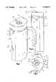
- FIG. 1is a perspective view of a hand held bar code dataform reader of the present invention
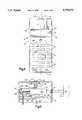
- FIG. 2is a side elevation view of the bar code dataform reader of FIG. 1;
- FIG. 3is a top plan view of the bar code dataform reader of FIG. 1 as seen from a plane indicated by the line 3--3 in FIG. 1;
- FIG. 4is a front elevation view of the bar code dataform reader of FIG. 1 is seen from a plane indicated by the line 4--4 in FIG. 3;
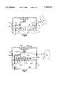
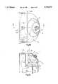
- FIG. 5is an enlarged fragmentary sectional view of a reading assembly of the bar code dataform reader of FIG. 1 showing the reading assembly mounted on rotatable support;
- FIG. 6is an enlarged fragmentary sectional view of the reading assembly of FIG. 4 with a mirror supported by the housing to deflect a direction of a light beam emitted by the reading assembly;
- FIG. 7is an enlarged fragmentary sectional view of a reading assembly mounted on a rotatable support, the support being rotatably driven by a stepper motor;
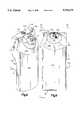
- FIG. 8is a perspective view of an alternate embodiment of the bar code dataform reader of present invention wherein the reading assembly is mounted on a support which rotates nearly 360° to permit reading along a cone shaped reading plane;
- FIG. 9is a back elevation view of the bar code dataform reader of FIG. 8;
- FIG. 10is top plan view of the bar code dataform reader of FIG. 8 as seen from a plane indicated by the line 10--10 in FIG. 9;
- FIG. 11is a side elevation view of the bar code dataform reader of FIG. 8 as seen from a plane indicated by the line 11--11 in FIG. 8;
- FIG. 12is an enlarged fragmentary sectional view of a reading assembly of the bar code dataform reader of FIG. 8 showing the reading assembly mounted on rotatable support;
- FIG. 13is another embodiment of the bar code dataform reader of the present invention having a single wraparound exit window
- FIG. 14is a front elevation view of the bar code dataform reader of FIG. 13.
- FIG. 15is a side elevation view of the bar code dataform reader of FIG. 13 as seen from a plane indicated by the line 15--15 in FIG. 14.
- FIG. 1-5illustrate a portable, hand held bar code dataform reader of the present invention.
- the readershown generally at 10, includes a housing 12 comprised of a durable, light-weight high impact polymer material.
- the housing 12defines an interior region 13 (FIG. 5) in which electrical circuitry of the reader (not shown), including a microprocessor mounted on one or more printed circuit boards, (not shown) is supported.
- the housing 12includes a front face 14 (best seen in FIG. 4) and an arcuate back face 16 (best seen in FIG. 1) separated by a side wall.
- the side wallincludes two vertical portions 18, 20, a top portion 20 and a bottom portion 21.
- the front face 14comprises an upper surface 22 and a lower surface 24.
- the upper surface 22is generally planar and is connected to the lower surface 24, which is also generally planar, by a slanted portion 25 of the front face.
- the front face lower surface 24supports a keypad including a plurality of key switches 26.
- the upper surface 22supports a display panel 28.
- the key switches 26 and the display panel 28are appropriately coupled to the electrical circuitry of the reader 10.
- the housing 12is adapted to be grasped in one hand of an operator (not shown) with the operator's thumb, palm and fingers cradling the back face 16 and vertical side walls 22, 24. The operator's free hand is used to actuate the keypad key switches 26.
- the display panel 28 and the keypad key switches 26face the operator.
- the display panel 28may be a liquid crystal display or any other suitable visual display panel.
- the housing 12additionally includes three rectangular openings which support three exit windows 30, 32, 34.
- One exit window 30is arcuate and is disposed in an opening in the housing back face 16, while the exit windows 32, 34 are disposed in the openings in the vertical side walls 18, 20 respectively.
- the exit windows 30, 32, 34are comprised of transparent plastic or glass.
- the housing 12also includes apertures through which button portions of momentary actuation switches 36, 38, 40, 42 extend.
- the actuation switches 36, 38, 40, 42are coupled between power supply circuitry (not shown) and a bar code dataform reading assembly 50 (FIG. 5) disposed in the housing interior region 13. Depressing any of the actuation switches 36, 38, 40, 42 energizes the reading assembly 50 and commences a bar code dataform reading session to read a bar code dataform 52 (shown in profile in FIG. 5) affixed to an item 54.
- the button portions of the actuation switches 36, 38, 40, 42are overlied by a durable, flexible material (not shown) which adheres to the housing to seal the apertures and prevent environmental contaminants from entering the housing interior region 13.
- the actuation switch 36extends through the housing front face 14 and is positioned to be depressed by a thumb of the operator's hand cradling the reader 10.
- the actuation switches 38, 40, 42are mounted in the top side wall 20 and the vertical side walls 18, 20 respectively. These actuation switches 38, 40, 42 are provided to allow the operator to easily institute a bar code dataform reading session with his or her free hand regardless of the position of reader 10.
- the bar code dataform reader 10includes the bar code dataform reading assembly 50 (shown schematically in FIG. 5).
- the reading assembly 50is mounted on a rotatable support 56.
- the rotatable support 56is, in turn, disposed on a horizontal member 58.
- the horizontal member 58is attached to an inner wall 60 of the housing 12 and includes a circular recess 62 into which an extending portion 64 of the rotatable support 56 rotatably interfits. Because the bar code dataform reading assembly 50 is mounted on the support 56, rotating the support also rotates the reading assembly.
- the bar code dataform reading assembly 50is of conventional design and a number of suitable reading assemblies are available from various vendors.
- One category of suitable reading assembliesincludes laser scanning assemblies.
- Another category of suitable bar code reading assembliesincludes image sensing array readers.
- a laser scanning assemblyincludes a laser and optics, for generating a beam of light.
- An oscillating mirrordirects the light beam toward a bar code to be read and sweeps the beam back and forth across the bar code.
- the oscillation of the mirrorcauses the light beam to reciprocate defining a reading plane which is perpendicular to an axis of oscillation of the mirror.
- the reading planeis triangular in shape and has as its origin the oscillating mirror.
- the lasermay be mounted to an oscillating mechanism to cause the laser itself to oscillate thereby sweeping the emitted light beam back and forth across the bar code to be read. Some of the light striking the bar code is reflected.
- An intensity of the reflected lightvaries as a function of composition of the bar code, that is, the individual bars and spaces comprising the bar code.
- the laser scanning assemblyincludes a photodiode which is positioned to detect the variable intensity of reflected illumination from the bar code.
- Signal processing circuitryoperates to generate a signal representative of the variable intensity reflected illumination.
- Appropriate laser scanning assembliesinclude the Model SE-1000 from Symbol Technologies of Bohemia, New York or the Model 5303 available from PSC Inc. of Webster, N.Y.
- the reading assembly 50includes an oscillating light source, schematically represented at 66 (as noted above the "light source” may be, for example, an oscillating mirror in a laser scanning assembly in which the mirror oscillates or the "light source” may be an oscillating laser in a laser scanning assembly in which the laser oscillates).
- the light source 66directs an oscillating beam of light through the exit window 32 along an optical path labeled X toward the bar code dataform 52 affixed to the item 54. The light strikes the bar code 52 and is reflected.
- Some of the light reflected from the bar code dataform 52follows a path labeled Y which enters the housing 12 through the exit window 32 where the reflected light strikes a light sensitive member such as a photodiode 68.
- the photodiode 68generates electrical signals which vary as a function of an intensity of the reflected light striking it.
- Decoder circuitry(not shown) is electrically coupled to the photodiode 68. The decoder circuitry converts signals generated by the photodiode 68 into machine readable data corresponding to the data encoded in the bar code dataform 52.
- the light source 66oscillates or reciprocates to repetitively sweep the light beam across the bar code dataform 52.
- the oscillation of the light source 66is along an axis of oscillation parallel to a central longitudinal axis L-L of the housing 12 (FIG. 4).
- the rotatable support 58has been rotated 90 degrees from the position shown in FIG. 5.
- the support 58is positioned such that the reading assembly 50 reads a bar code through the exit window 30.
- the optical path defined by the oscillating light beamforms a triangular shaped bar code reading plane represented by S in FIG. 3.
- the reading plane Sis extends outwardly from the light source 66 between boundaries which are represented by rays X 1 and X 2 .
- the rays X 1 X 2define a sweep angle A.
- the light beamsweeps over the bar code dataform 52.
- a turret 70is attached to the rotatable support 56 and extends through an opening in the housing 12. Attached to the turret 70, exterior of the housing 12, is knurled knob 72. The knob 72 is disposed in a recessed portion 74 of the housing 12. The knob 70 permits an operator to rotate the support 56 and the reading assembly 50 mounted to it. By turning the knob 70 the operator can selectively position the reading assembly 50 to read out of exit window 30 (FIG. 3), exit window 32 (FIG. 5) or exit window 34 (not shown).
- the knob 72includes a raised portion 76 (best seen in FIGS. 1 & 3) forming an arrow. As can be seen in FIG.
- the raised portion 66is aligned with the reading assembly 50 such that the arrow points in a direction of reading, that is, the arrow generally points along a line which, when viewed from above the reader 10, would approximately bisect the reading plane S (see FIG. 3).
- a biasing spring 77is disposed between the support 56 and the housing inner wall 60 to bias the support against the horizontal member 58.
- a sealing 0-ring 79is disposed between the turret 70 and the opening of the housing 12 to prevent contaminants from entering the housing interior region 13.
- the support 56is indexed between three positions which are 90 degrees apart.
- the three indexing positionscorrespond to the three reading positions of the reading assembly 50. That is, in one index position of the rotatable support 56, the reading assembly 50 reads a bar code through the exit window 30. In a second support index position, the reading assembly 50 reads a bar code through the exit window 32. In the third support index position,.the reading assembly 50 reads a bar code through the exit window 34 (also not shown).
- the indexing positions of the support 56are defined by a detent locking mechanism which releasably locks the support in a selected one of the indexing positions.
- the rotatable support 56includes a recess.
- the detent locking mechanismincludes a ball 80 and a spring 82 which are confine between the recess and an upper surface 84 of the horizontal member 58.
- the horizontal member 58includes three spaced apart indentations 86 (only one of which can be seen in FIG. 5).
- the ball 80biased downwardly against the member 58 by the spring 82, rolls across the horizontal member upper surface until it "drops" into one of the indentations 86.
- the indentation 86defines one of the support indexing positions.
- the ball 80 resting in the indentation 86locks the support 56 in place for a reading session through the exit window 34.
- the indentation 86is relatively shallow so the ball 80 only drops part way into the indentation. The operator, therefore, does not have to exert a large rotational force on the knob 72 to move the support between indexing positions.
- the configuration of the indentations 86, the rotatable support 56 and the reading assembly 50is such that at each of the detent locking positions, the reading assembly 50 is oriented to read (that is, direct the oscillating light beam) out a different one of the exit windows 30, 32, 34. Stops (not shown) are provided to prevent the operator from rotating the knob 72 toward the operator, that is, past the indexing positions associated with exit windows 32, 34. The stops are necessary for two reasons. First, since there are only three support indexing positions, there is no need for the operator to rotate the support 56 to any other position. Second, a ribbon cable 88 connects the reading assembly 50 to other electronic circuitry (not shown) mounted on one or more printed circuit boards in the housing interior region 13.
- An exit window blocking plate 89extends outwardly from the support 56 opposite a direction of the light source 66.
- the blocking plate 89has three plate portions which are at the level of the exit windows 30, 32, 34. Whichever exit window the reading assembly 50 is oriented to read through, two of the plate portions will be adjacent to and overlying the other two exit window.
- the outwardly facing sides of the plate portionsmay be advantageously coated with a high luminescence coating so the operator can easily see which exit windows are "covered", that is, which windows the light beam will not be emitted through.
- the optical path Xis generally perpendicular to the exit windows 30, 32, 34. However, it may be desirable to have the light beam travel along an optical path which is not perpendicular to the exit windows, for example, along a path X' as shown in FIG. 6. Such a deflection or folding of the light beam is easily accomplished in the present invention with minor modification.
- a light folding mirror 90 affixed to a support 91is positioned to fold a light beam emitted by a bar code reading assembly 50' along the optical path X'.
- the support 91is affixed to the housing inner wall 60 and folds the light beam emitted by the light source 66' along the optical path X'.
- each of the exit windows 30, 32, 34may or may not be equipped with a beam folding mirror.
- the angle of folding for each exit windowmay be different, e.g., a mirror adjacent one exit window may be oriented to fold the light beam upwardly through the exit window at a 30 degree angle (as shown in FIG. 6) while another mirror adjacent another exit window may be oriented to fold the light beam at a downward angle of 45 degrees through the exit window.
- the reader 100includes a housing 102 defining an interior region 103 (FIG. 12). Disposed in the interior region 103 is a bar code dataform reading assembly 104 coupled by a ribbon cable 106 to electrical circuitry (not shown) of the reader 100.
- the housing 102includes a front face 108 and back face 110 separated by a side wall.
- the side wallincludes two vertical portions 112, 114, a top portion 116 and a bottom portion 118.
- the back face 110includes a curved upper region 119.
- the upper region 119includes an outer portion 119a and an inner portion 119b which are an aligned series of arcuate openings into which circular shaped exit window 120 is disposed.
- the reading assembly 104is mounted on a rotatable support 122.
- the support 122in turn, is affixed to a turret 124.
- One end of the turret 126is rotatably mounted in an opening in a right angled support member 128 which extends vertically downward from the top side wall 116 and horizontally inward from the front face 110.
- a knurled knob 130is affixed to an opposite end the turret 126.
- the knob 130seats in a recessed circular portion of the inner portion 119b of the upper region 119.
- the reading assembly 104includes a light source 132.
- the reading assembly 104is actuated for a bar code reading session by depressing one of the actuation switches 140, 142, 144, 146.
- a light beam generated by the light source 132 upon actuation of the reading assemblyis directed through the exit window 120 along an optical path Y.
- turning the knob 130 180 degreesrotates the support 122 and the reading assembly 104 such that, upon actuation, the light beam generated by the light source 132 exits the exit window 120 along an optical path Y'.
- Angle B1represents the angle between the optical path Y and a central axis T--T through the turret 124 while angle B2 represents the angle between the angle between the optical path Y' and the central axis T--T.
- angles B1 and B1are shown as approximately 45 degree angles, it should be understood that by changing the shape of the reading assembly 104 and/or the support 122, the optical path Y and therefore the angles B1 and B2 could easily be changed.
- FIG. 11shows in dashed line a circle C representing all possible optical paths including Y and Y' as the knob 130 is rotated.
- the optical pathsform a cone having an imaginary vertex represented by R in FIGS. 11 and 12.
- the vertex Rlies along the central axis T--T of the turret 124.
- the vertex Ris imaginary, of course, because the optical paths do not originate at R but rather originate from the light source 122.
- the light source 122moves along a circular path of travel having a center point on the central axis T--T. Projecting the optical paths backward through the light source 122 as shown in dashed lines in FIG. 11 and 12 results in the intersection point or vertex R.
- the shape of the exit window 120is easily determined by projecting the cone shaped optical paths onto the housing 102. That is, where the cone represented by circle C and vertex R intersects the housing 102, the exit window 120 must be present to allow the light beam to exit the housing. Points P and P' in FIG. 12 are illustrative of two points of intersection between the cone and the housing. The exit window 120 must be present at P and P' to permit optical paths Y and Y' to be realized. Optical path Y would be utilized to read bar code 52 on item 54, while optical path Y' would be utilized to read bar code 52' on item 54'.
- a detent mechanism(not shown) is provided between the turret 124 and the support member 128 to releasably secure the support in a selected one of a plurality of bar code dataform reading positions. Since the exit window 120 is for all intents and purposes continuous and the reading assembly 104 is always oriented to read through the window, the detent mechanism may provide for a large number of support positions in almost a full 360 degree range of support positions. For example, the detent mechanism may provide for locking positions for the support every 20 degrees. That is, at every 20 degree turn of the knob, a ball (not shown) will drop into a corresponding indentation (not shown) to lock the support 122 and the reading mechanism 104 is a stable position so a reading session may be commenced.
- a stopis also provided to prevent the knob 130 from being turned more than 360 degrees. The stop is necessary to prevent the ribbon cable 106 from being pulled away from the reader electronic circuitry and/or the reading assembly 104 which would likely result in damage to the cable, the circuitry and/or the reading assembly.
- the reader 200includes a housing 202 defining an interior region 204 in which a bar code dataform reading assembly 250 is disposed.
- the interior region 204also supports reader electronic circuitry (not shown) mounted on one or more printed circuit boards.
- the housing 202includes a front face 206 and a back face 208 separated by a side wall.
- the side wallincludes a top portion 210, a bottom portion 212 and two vertical portions 214, 216.
- the front face 206supports a visual display panel 218 and key switches 220 defining a keypad.
- the housing 202includes an opening which supports an exit window 230.
- the exit window 230extends across the back face 208 and substantially all of the vertical side walls 214, 216, of the housing and portions of vertical side walls 206, 208.
- Momentary actuation switches 232, 234, 236, 238extend through apertures in the housing 202.
- the reading assembly 250is actuated to commence a bar code reading session by depressing any one of the actuation switches.
- the reading assembly 250is mounted on a rotatable support 256.
- the support 256in turn, is mounted on a horizontal member 258 which extends from an inner wall 260 of the housing 202.
- a bottom portion of the support 256includes an extending member 262 which rotatably fits into an opening in the horizontal member 258.
- the bottom portion of the support 256also includes an annular portion 264 having gear teeth on its outer periphery.
- a stepper motor 270is secured to the housing inner wall 260 by a bracket 272.
- the motor 270includes a shaft 274 to which is pinned a gear 276.
- the gear 276interfits with the geared periphery of the annular portion 264 of the support 256 to rotate the support into a bar code reading position.
- three stepper motor actuation key switches 280, 282, 284extend through apertures in the housing 202. The operator depresses a selected one of three switches to actuate the stepper motor 270.
- Each switch 280, 282, 284is associated with a different support position.
- depressing switch 280would cause the stepper motor 270 to rotate the support 256 and the reading assembly 250 mounted thereto so that reading a bar code 52 will occur along an optical path X" which exits through a portion of the exit window 230 in the vertical side wall 216.
- Depressing switch 282would cause the stepper motor 270 to rotate the support 256 and the reading assembly 250 mounted thereto so that the optical path X" exits through a portion of the exit window 230 in the back face 208.
- depressing switch 284would cause the stepper motor 270 to rotate the support 256 and the reading assembly 250 mounted thereto so that the optical path X" exits through a portion of the exit window 230 in the vertical side wall 216.
- the support 256includes a turret 290 which extends through an opening in the housing 202.
- An end of the turret 290 which is exterior of the housing 202includes a knob 292 with a raised arrow 294 (best seen in FIG. 13).
- the arrow 294points in the direction of the optical path X" so the operator can visually verify that the reader 200 will be reading in the desired reading direction prior to actuating the reading assembly 250.
Landscapes
- Physics & Mathematics (AREA)
- Electromagnetism (AREA)
- Engineering & Computer Science (AREA)
- Health & Medical Sciences (AREA)
- General Health & Medical Sciences (AREA)
- Toxicology (AREA)
- Artificial Intelligence (AREA)
- Computer Vision & Pattern Recognition (AREA)
- General Physics & Mathematics (AREA)
- Theoretical Computer Science (AREA)
- Mechanical Optical Scanning Systems (AREA)
Abstract
Description
Claims (20)
Priority Applications (1)
| Application Number | Priority Date | Filing Date | Title |
|---|---|---|---|
| US08/519,849US5750975A (en) | 1995-08-25 | 1995-08-25 | Hand held bar code dataform reader having a rotatable reading assembly |
Applications Claiming Priority (1)
| Application Number | Priority Date | Filing Date | Title |
|---|---|---|---|
| US08/519,849US5750975A (en) | 1995-08-25 | 1995-08-25 | Hand held bar code dataform reader having a rotatable reading assembly |
Publications (1)
| Publication Number | Publication Date |
|---|---|
| US5750975Atrue US5750975A (en) | 1998-05-12 |
Family
ID=24070060
Family Applications (1)
| Application Number | Title | Priority Date | Filing Date |
|---|---|---|---|
| US08/519,849Expired - LifetimeUS5750975A (en) | 1995-08-25 | 1995-08-25 | Hand held bar code dataform reader having a rotatable reading assembly |
Country Status (1)
| Country | Link |
|---|---|
| US (1) | US5750975A (en) |
Cited By (7)
| Publication number | Priority date | Publication date | Assignee | Title |
|---|---|---|---|---|
| US6513716B2 (en)* | 2000-05-29 | 2003-02-04 | Sysmex Corporation | Automatic apparatus for reading bar codes and an automatic analyzer provided therewith |
| US20030034395A1 (en)* | 1999-06-07 | 2003-02-20 | Metrologic Instruments, Inc. | Planar light illumination and imaging (PLIIM) based system having a linear image detection chip mounting assembly with means for preventing misalignment between the field of view (FOV) of said linear image detection chip and the co-planar laser illumination beam (PLIB) produced by said PLIIM based system, in response to thermal expansion and/or contraction within said PLIIM based system |
| US6575368B1 (en)* | 1996-01-31 | 2003-06-10 | Psc Scanning, Inc. | Multiple aperture data reader for multi-mode operation |
| US20040134989A1 (en)* | 2003-01-09 | 2004-07-15 | Hand Held Products, Inc. | Decoder board for an optical reader utilizing a plurality of imaging formats |
| USD527008S1 (en)* | 2004-10-20 | 2006-08-22 | Edward Pryor & Son Limited | Optical code reader |
| USD724088S1 (en)* | 2014-07-16 | 2015-03-10 | Spx Corporation | Remote fare reader |
| US20200380218A1 (en)* | 2019-06-03 | 2020-12-03 | Zebra Technologies Corporation | Digital Barcode Reader |
Citations (37)
| Publication number | Priority date | Publication date | Assignee | Title |
|---|---|---|---|---|
| US4387297A (en)* | 1980-02-29 | 1983-06-07 | Symbol Technologies, Inc. | Portable laser scanning system and scanning methods |
| US4412751A (en)* | 1981-08-25 | 1983-11-01 | Omega Sa | Jointed electronic watch |
| US4460120A (en)* | 1982-01-25 | 1984-07-17 | Symbol Technologies, Inc. | Narrow bodied, single- and twin-windowed portable laser scanning head for reading bar code symbols |
| US4593186A (en)* | 1980-02-29 | 1986-06-03 | Symbol Technologies, Inc. | Portable laser scanning system and scanning methods |
| US4621189A (en)* | 1985-10-08 | 1986-11-04 | Telxon Corporation | Hand held data entry apparatus |
| US4660221A (en)* | 1983-07-18 | 1987-04-21 | Pitney Bowes Inc. | System for printing encrypted messages with bar-code representation |
| US4758717A (en)* | 1982-01-25 | 1988-07-19 | Symbol Technologies, Inc. | Narrow-bodied, single-and twin-windowed portable laser scanning head for reading bar code symbols |
| USD297939S (en) | 1986-05-12 | 1988-10-04 | Clinicom Incorporated | Combined portable handheld terminal and optical bar code reader |
| US4794239A (en)* | 1987-10-13 | 1988-12-27 | Intermec Corporation | Multitrack bar code and associated decoding method |
| US4835713A (en)* | 1985-08-06 | 1989-05-30 | Pitney Bowes Inc. | Postage meter with coded graphic information in the indicia |
| USD303663S (en) | 1986-10-01 | 1989-09-26 | Telxon Corporation | Combined hand held keyboard and display terminal and optical scanning head |
| US4889982A (en)* | 1987-08-19 | 1989-12-26 | Storage Technology Corporation | Encoded label having redundant and scrambled indicia for identifying a magnetic tape cartridge |
| US4916441A (en)* | 1988-09-19 | 1990-04-10 | Clinicom Incorporated | Portable handheld terminal |
| USD309295S (en) | 1988-01-29 | 1990-07-17 | Marquette Electronics, Inc. | Data terminal |
| US5015831A (en)* | 1988-11-07 | 1991-05-14 | Photographic Sciences Corporation | Scan modules for bar code readers and the like in which scan elements are flexurally supported |
| US5043854A (en)* | 1990-08-10 | 1991-08-27 | Gammache Richard J | Flashlight with swivel head |
| US5113445A (en)* | 1990-07-09 | 1992-05-12 | Symbol Technologies Inc. | System for encoding data in machine readable graphic form |
| US5123064A (en)* | 1989-09-29 | 1992-06-16 | Norand Corporation | Hand-held data entry system and removable signature pad module therefor |
| US5130207A (en)* | 1990-11-13 | 1992-07-14 | Alliant Tech Systems Inc. | Thin wall steel cartridge cases |
| US5144120A (en)* | 1988-05-11 | 1992-09-01 | Symbol Technologies, Inc. | Mirrorless scanners with movable laser, optical and sensor components |
| US5202817A (en)* | 1989-06-07 | 1993-04-13 | Norand Corporation | Hand-held data capture system with interchangeable modules |
| USD334922S (en) | 1991-09-25 | 1993-04-20 | Telxon Corporation | Bar code scanner |
| US5216233A (en)* | 1989-03-09 | 1993-06-01 | Norand Corporation | Versatile RF terminal-scanner system |
| US5227617A (en)* | 1989-12-28 | 1993-07-13 | Monarch Marking Systems, Inc. | Hand-held label applicator with scanned data acquistion and selective data retrieval acquistion |
| US5227614A (en)* | 1986-08-15 | 1993-07-13 | Norand Corporation | Core computer processor module, and peripheral shell module assembled to form a pocket size data capture unit |
| US5237161A (en)* | 1991-06-05 | 1993-08-17 | Psc, Inc. | System for automatically reading symbols, such as bar codes, on objects which are placed in the detection zone of a symbol reading unit, such as a bar code scanner |
| US5243655A (en)* | 1990-01-05 | 1993-09-07 | Symbol Technologies Inc. | System for encoding and decoding data in machine readable graphic form |
| USD340034S (en) | 1991-06-14 | 1993-10-05 | Telxon Corporation | Handheld computer with built-in bar code scanner |
| US5304786A (en)* | 1990-01-05 | 1994-04-19 | Symbol Technologies, Inc. | High density two-dimensional bar code symbol |
| US5324925A (en)* | 1992-09-25 | 1994-06-28 | Norand Corporation | Hand-held data terminal and communicator |
| US5331136A (en)* | 1990-01-18 | 1994-07-19 | Norand Corporation | Hand-held data capture system with interchangeable modules |
| US5337361A (en)* | 1990-01-05 | 1994-08-09 | Symbol Technologies, Inc. | Record with encoded data |
| US5367152A (en)* | 1988-05-11 | 1994-11-22 | Symbol Technologies, Inc. | Method of reading indicia from either side of scanner housing |
| US5406063A (en)* | 1993-05-07 | 1995-04-11 | Telxon Corporation | Hand-held data scanner having adjustable keyboard panel |
| US5471042A (en)* | 1988-05-11 | 1995-11-28 | Symbol Technologies, Inc. | Handheld data entry terminal having dual trigger switches |
| US5477044A (en)* | 1994-07-22 | 1995-12-19 | Intermec Corporation | Symbology reader with a variable orientation head |
| US5479002A (en)* | 1988-05-11 | 1995-12-26 | Symbol Technologies, Inc. | Bar code scanner with scanning beam and/or field of view adjustable about three mutually orthogonal axes |
- 1995
- 1995-08-25USUS08/519,849patent/US5750975A/ennot_activeExpired - Lifetime
Patent Citations (39)
| Publication number | Priority date | Publication date | Assignee | Title |
|---|---|---|---|---|
| US4387297A (en)* | 1980-02-29 | 1983-06-07 | Symbol Technologies, Inc. | Portable laser scanning system and scanning methods |
| US4387297B1 (en)* | 1980-02-29 | 1995-09-12 | Symbol Technologies Inc | Portable laser scanning system and scanning methods |
| US4593186A (en)* | 1980-02-29 | 1986-06-03 | Symbol Technologies, Inc. | Portable laser scanning system and scanning methods |
| US4412751A (en)* | 1981-08-25 | 1983-11-01 | Omega Sa | Jointed electronic watch |
| US4758717A (en)* | 1982-01-25 | 1988-07-19 | Symbol Technologies, Inc. | Narrow-bodied, single-and twin-windowed portable laser scanning head for reading bar code symbols |
| US4460120A (en)* | 1982-01-25 | 1984-07-17 | Symbol Technologies, Inc. | Narrow bodied, single- and twin-windowed portable laser scanning head for reading bar code symbols |
| US4660221A (en)* | 1983-07-18 | 1987-04-21 | Pitney Bowes Inc. | System for printing encrypted messages with bar-code representation |
| US4835713A (en)* | 1985-08-06 | 1989-05-30 | Pitney Bowes Inc. | Postage meter with coded graphic information in the indicia |
| US4621189A (en)* | 1985-10-08 | 1986-11-04 | Telxon Corporation | Hand held data entry apparatus |
| USD297939S (en) | 1986-05-12 | 1988-10-04 | Clinicom Incorporated | Combined portable handheld terminal and optical bar code reader |
| US5227614A (en)* | 1986-08-15 | 1993-07-13 | Norand Corporation | Core computer processor module, and peripheral shell module assembled to form a pocket size data capture unit |
| USD303663S (en) | 1986-10-01 | 1989-09-26 | Telxon Corporation | Combined hand held keyboard and display terminal and optical scanning head |
| US4889982A (en)* | 1987-08-19 | 1989-12-26 | Storage Technology Corporation | Encoded label having redundant and scrambled indicia for identifying a magnetic tape cartridge |
| US4794239A (en)* | 1987-10-13 | 1988-12-27 | Intermec Corporation | Multitrack bar code and associated decoding method |
| USD309295S (en) | 1988-01-29 | 1990-07-17 | Marquette Electronics, Inc. | Data terminal |
| US5367152A (en)* | 1988-05-11 | 1994-11-22 | Symbol Technologies, Inc. | Method of reading indicia from either side of scanner housing |
| US5471042A (en)* | 1988-05-11 | 1995-11-28 | Symbol Technologies, Inc. | Handheld data entry terminal having dual trigger switches |
| US5479002A (en)* | 1988-05-11 | 1995-12-26 | Symbol Technologies, Inc. | Bar code scanner with scanning beam and/or field of view adjustable about three mutually orthogonal axes |
| US5144120A (en)* | 1988-05-11 | 1992-09-01 | Symbol Technologies, Inc. | Mirrorless scanners with movable laser, optical and sensor components |
| US4916441A (en)* | 1988-09-19 | 1990-04-10 | Clinicom Incorporated | Portable handheld terminal |
| US5015831A (en)* | 1988-11-07 | 1991-05-14 | Photographic Sciences Corporation | Scan modules for bar code readers and the like in which scan elements are flexurally supported |
| US5216233A (en)* | 1989-03-09 | 1993-06-01 | Norand Corporation | Versatile RF terminal-scanner system |
| US5202817A (en)* | 1989-06-07 | 1993-04-13 | Norand Corporation | Hand-held data capture system with interchangeable modules |
| US5123064A (en)* | 1989-09-29 | 1992-06-16 | Norand Corporation | Hand-held data entry system and removable signature pad module therefor |
| US5227617A (en)* | 1989-12-28 | 1993-07-13 | Monarch Marking Systems, Inc. | Hand-held label applicator with scanned data acquistion and selective data retrieval acquistion |
| US5337361C1 (en)* | 1990-01-05 | 2001-05-15 | Symbol Technologies Inc | Record with encoded data |
| US5243655A (en)* | 1990-01-05 | 1993-09-07 | Symbol Technologies Inc. | System for encoding and decoding data in machine readable graphic form |
| US5304786A (en)* | 1990-01-05 | 1994-04-19 | Symbol Technologies, Inc. | High density two-dimensional bar code symbol |
| US5337361A (en)* | 1990-01-05 | 1994-08-09 | Symbol Technologies, Inc. | Record with encoded data |
| US5331136A (en)* | 1990-01-18 | 1994-07-19 | Norand Corporation | Hand-held data capture system with interchangeable modules |
| US5113445A (en)* | 1990-07-09 | 1992-05-12 | Symbol Technologies Inc. | System for encoding data in machine readable graphic form |
| US5043854A (en)* | 1990-08-10 | 1991-08-27 | Gammache Richard J | Flashlight with swivel head |
| US5130207A (en)* | 1990-11-13 | 1992-07-14 | Alliant Tech Systems Inc. | Thin wall steel cartridge cases |
| US5237161A (en)* | 1991-06-05 | 1993-08-17 | Psc, Inc. | System for automatically reading symbols, such as bar codes, on objects which are placed in the detection zone of a symbol reading unit, such as a bar code scanner |
| USD340034S (en) | 1991-06-14 | 1993-10-05 | Telxon Corporation | Handheld computer with built-in bar code scanner |
| USD334922S (en) | 1991-09-25 | 1993-04-20 | Telxon Corporation | Bar code scanner |
| US5324925A (en)* | 1992-09-25 | 1994-06-28 | Norand Corporation | Hand-held data terminal and communicator |
| US5406063A (en)* | 1993-05-07 | 1995-04-11 | Telxon Corporation | Hand-held data scanner having adjustable keyboard panel |
| US5477044A (en)* | 1994-07-22 | 1995-12-19 | Intermec Corporation | Symbology reader with a variable orientation head |
Non-Patent Citations (6)
| Title |
|---|
| Article by Symbol Technologies, Inc. Entitled "A Primer for Two Dimensional Bar Codes, Portable Data Files and PDF417", Bohemia, NY, dated Oct. 1990. |
| Article by Symbol Technologies, Inc. Entitled A Primer for Two Dimensional Bar Codes, Portable Data Files and PDF417 , Bohemia, NY, dated Oct. 1990.* |
| Monicor Electronic Corp. brochure for Monicor Model IC 100 radio modem entitled Monicor snap on radio modem for Mars Electronics MEQ terminals. To the best of Applicants knowledge, the Monicor brochure was published more than one year prior to Applicants filing date of Aug. 25, 1995.* |
| Monicor Electronic Corp. Brochure for Monicor Model IC 100 Radio Modern Entitled Monicor Snap On Radio Modem for Mars Electronics MEQ Terminals, undated.* |
| Monicor Electronic Corp. brochure for Monicor Model IC-100 radio modem entitled "Monicor snap-on radio modem for Mars Electronics MEQ™ terminals." To the best of Applicants' knowledge, the Monicor brochure was published more than one year prior to Applicants' filing date of Aug. 25, 1995. |
| Monicor Electronic Corp. Brochure for Monicor Model IC-100 Radio Modern Entitled "Monicor Snap-On Radio Modem for Mars Electronics MEQ™ Terminals," undated. |
Cited By (20)
| Publication number | Priority date | Publication date | Assignee | Title |
|---|---|---|---|---|
| US7243850B2 (en) | 1996-01-31 | 2007-07-17 | Psc Scanning, Inc. | Data reader for multi-mode operation |
| US6575368B1 (en)* | 1996-01-31 | 2003-06-10 | Psc Scanning, Inc. | Multiple aperture data reader for multi-mode operation |
| US6719201B2 (en) | 1996-01-31 | 2004-04-13 | Psc Scanning, Inc. | Multiple aperture data reader for multi-mode operation |
| US20040169084A1 (en)* | 1996-01-31 | 2004-09-02 | Psc Scanning, Inc. | Multiple aperture data reader for multi-mode operation |
| US20050224583A1 (en)* | 1996-01-31 | 2005-10-13 | Psc Scanning, Inc. | Multiple aperture data reader for multi-mode operation |
| US7051940B2 (en) | 1996-01-31 | 2006-05-30 | Psc Scanning, Inc. | Data reader for multi-mode operation |
| US20030034395A1 (en)* | 1999-06-07 | 2003-02-20 | Metrologic Instruments, Inc. | Planar light illumination and imaging (PLIIM) based system having a linear image detection chip mounting assembly with means for preventing misalignment between the field of view (FOV) of said linear image detection chip and the co-planar laser illumination beam (PLIB) produced by said PLIIM based system, in response to thermal expansion and/or contraction within said PLIIM based system |
| US6978935B2 (en)* | 1999-06-07 | 2005-12-27 | Metrologic Instruments, Inc. | Planar light illumination and imaging (pliim) based system having a linear image detection chip mounting assembly with means for preventing misalignment between the field of view (fov) of said linear image detection chip and the co-planar laser illumination beam (plib) produced by said pliim based system, in response to thermal expansion and/or contraction within said pliim based system |
| US6513716B2 (en)* | 2000-05-29 | 2003-02-04 | Sysmex Corporation | Automatic apparatus for reading bar codes and an automatic analyzer provided therewith |
| US8622303B2 (en) | 2003-01-09 | 2014-01-07 | Hand Held Products, Inc. | Decoding utilizing image data |
| US7086596B2 (en) | 2003-01-09 | 2006-08-08 | Hand Held Products, Inc. | Decoder board for an optical reader utilizing a plurality of imaging formats |
| US7690572B2 (en) | 2003-01-09 | 2010-04-06 | Hand Held Products, Inc. | Decoder board for an optical reader utilizing a plurality of imaging formats |
| US20100187310A1 (en)* | 2003-01-09 | 2010-07-29 | Hand Held Products, Inc. | Decoder board for an optical reader utilizing a plurality of imaging formats |
| US8016196B2 (en) | 2003-01-09 | 2011-09-13 | Hand Held Products, Inc. | Decoder board for an optical reader utilizing a plurality of imaging formats |
| US20040134989A1 (en)* | 2003-01-09 | 2004-07-15 | Hand Held Products, Inc. | Decoder board for an optical reader utilizing a plurality of imaging formats |
| US9152835B2 (en) | 2003-01-09 | 2015-10-06 | Hand Held Products, Inc. | Decoding utilizing image data |
| USD527008S1 (en)* | 2004-10-20 | 2006-08-22 | Edward Pryor & Son Limited | Optical code reader |
| USD724088S1 (en)* | 2014-07-16 | 2015-03-10 | Spx Corporation | Remote fare reader |
| US20200380218A1 (en)* | 2019-06-03 | 2020-12-03 | Zebra Technologies Corporation | Digital Barcode Reader |
| US12141651B2 (en)* | 2019-06-03 | 2024-11-12 | Zebra Technologies Corporation | Digital barcode reader |
Similar Documents
| Publication | Publication Date | Title |
|---|---|---|
| EP0653722B1 (en) | Handheld data entry terminal having dual trigger switches | |
| AU650833B2 (en) | Mirrorless scanners with movable laser, optical and sensor components | |
| EP0431831B1 (en) | Optical scanning apparatus | |
| US5633489A (en) | Combination mouse and scanner for reading optically encoded indicia | |
| US6247647B1 (en) | Scan pattern generator convertible between multiple and single line patterns | |
| US6899271B2 (en) | Arrangement for and method of collecting and displaying information in real time along a line of sight | |
| US5021641A (en) | Hand-held bar code scanner with jointly mounted scanning mirrors | |
| EP0778538B1 (en) | Optical scanner | |
| US5656804A (en) | Apparatus and method for sensing motion of a portable terminal | |
| EP0742530B1 (en) | Mirrorless scanners with movable laser, optical and sensor components | |
| EP0517958B1 (en) | Combined range laser scanner | |
| EP0412680B1 (en) | Optical scanning system | |
| EP0490601B1 (en) | Optical scanning apparatus for reading coded symbols | |
| US5314631A (en) | Stationary bar code reader which can be detected and separated into a hand-held bar code reader | |
| EP0755018A2 (en) | Optical mark reader | |
| EP0490604B1 (en) | Optical scanning apparatus | |
| US5750975A (en) | Hand held bar code dataform reader having a rotatable reading assembly | |
| WO2001013158A1 (en) | Laser focusing aperture and method | |
| EP0995167B1 (en) | Method and device for reading of a barcode on an article | |
| EP0425274B1 (en) | Separate type bar code reader | |
| US5818025A (en) | Selective pattern scanner | |
| JP2002117370A (en) | Optical reading device | |
| JP3803240B2 (en) | Optical reader | |
| JPH04291477A (en) | Bar code scanning device | |
| JP3069191B2 (en) | Scanning head of optical scanning device |
Legal Events
| Date | Code | Title | Description |
|---|---|---|---|
| AS | Assignment | Owner name:TELETRANSACTIONS, INC., OHIO Free format text:ASSIGNMENT OF ASSIGNORS INTEREST;ASSIGNORS:MEYERSON, ROBERT F.;WALL, DANIEL G.;O'HAGAN, TIMOTHY P.;REEL/FRAME:007782/0424;SIGNING DATES FROM 19950925 TO 19951020 | |
| STCF | Information on status: patent grant | Free format text:PATENTED CASE | |
| AS | Assignment | Owner name:TELXON CORPORATION, OHIO Free format text:ASSIGNMENT OF ASSIGNORS INTEREST;ASSIGNOR:TELETRANSACTIONS, INC.;REEL/FRAME:009781/0759 Effective date:19990201 | |
| AS | Assignment | Owner name:BANK OF NEW YORK, THE, NEW YORK Free format text:SECURITY INTEREST;ASSIGNOR:TELXON CORPORATION;REEL/FRAME:009817/0901 Effective date:19990326 | |
| AS | Assignment | Owner name:BANK ONE, NA, OHIO Free format text:ASSIGNMENT OF ASSIGNORS INTEREST;ASSIGNOR:TELXON CORPORATION, A DELAWARE CORPORATION;REEL/FRAME:009866/0723 Effective date:19990326 | |
| AS | Assignment | Owner name:TELXON CORPORATION, OHIO Free format text:RELEASE BY SECURED PARTY;ASSIGNOR:THE BANK OF NEW YORK, AS AGENT;REEL/FRAME:010216/0776 Effective date:19990830 Owner name:TELXON CORPORATION, OHIO Free format text:RELEASE OF SECURITY INTEREST;ASSIGNOR:BANK ONE, NA;REEL/FRAME:010216/0050 Effective date:19990830 Owner name:FOOTHILL CAPITAL CORPORATION AS AGENT, CALIFORNIA Free format text:SECURITY INTEREST;ASSIGNOR:TELXON CORPORATION;REEL/FRAME:010216/0081 Effective date:19990826 | |
| FPAY | Fee payment | Year of fee payment:4 | |
| AS | Assignment | Owner name:SYMBOL TECHNOLOGIES, INC., NEW YORK Free format text:ASSIGNMENT OF ASSIGNORS INTEREST;ASSIGNOR:TELXON CORPORATION;REEL/FRAME:012795/0070 Effective date:20020327 | |
| AS | Assignment | Owner name:JPMORGAN CHASE BANK, N.A., NEW YORK Free format text:SECURITY INTEREST;ASSIGNOR:SYMBOL TECHNOLOGIES, INC.;REEL/FRAME:016116/0203 Effective date:20041229 | |
| AS | Assignment | Owner name:TELXON CORPORATION, OHIO Free format text:RELEASE OF SECURITY AGREEMENT;ASSIGNOR:WELLS FARGO FOOTHILL, INC. (FORMERLY FOOTHILL CAPITAL CORPORATION);REEL/FRAME:016621/0303 Effective date:20050716 | |
| FPAY | Fee payment | Year of fee payment:8 | |
| FPAY | Fee payment | Year of fee payment:12 | |
| AS | Assignment | Owner name:SYMBOL TECHNOLOGIES, INC., NEW YORK Free format text:RELEASE BY SECURED PARTY;ASSIGNOR:JPMORGANCHASE BANK, N.A.;REEL/FRAME:025441/0228 Effective date:20060901 | |
| AS | Assignment | Owner name:MORGAN STANLEY SENIOR FUNDING, INC. AS THE COLLATERAL AGENT, MARYLAND Free format text:SECURITY AGREEMENT;ASSIGNORS:ZIH CORP.;LASER BAND, LLC;ZEBRA ENTERPRISE SOLUTIONS CORP.;AND OTHERS;REEL/FRAME:034114/0270 Effective date:20141027 Owner name:MORGAN STANLEY SENIOR FUNDING, INC. AS THE COLLATE Free format text:SECURITY AGREEMENT;ASSIGNORS:ZIH CORP.;LASER BAND, LLC;ZEBRA ENTERPRISE SOLUTIONS CORP.;AND OTHERS;REEL/FRAME:034114/0270 Effective date:20141027 | |
| AS | Assignment | Owner name:SYMBOL TECHNOLOGIES, LLC, NEW YORK Free format text:CHANGE OF NAME;ASSIGNOR:SYMBOL TECHNOLOGIES, INC.;REEL/FRAME:036083/0640 Effective date:20150410 | |
| AS | Assignment | Owner name:SYMBOL TECHNOLOGIES, INC., NEW YORK Free format text:RELEASE BY SECURED PARTY;ASSIGNOR:MORGAN STANLEY SENIOR FUNDING, INC.;REEL/FRAME:036371/0738 Effective date:20150721 |