US5750966A - Plant for pasteurizing or sterilising solid or liquid food products using microwaves - Google Patents
Plant for pasteurizing or sterilising solid or liquid food products using microwavesDownload PDFInfo
- Publication number
- US5750966A US5750966AUS08/756,188US75618896AUS5750966AUS 5750966 AUS5750966 AUS 5750966AUS 75618896 AUS75618896 AUS 75618896AUS 5750966 AUS5750966 AUS 5750966A
- Authority
- US
- United States
- Prior art keywords
- tubular
- pressure
- plant
- tubular element
- elements
- Prior art date
- Legal status (The legal status is an assumption and is not a legal conclusion. Google has not performed a legal analysis and makes no representation as to the accuracy of the status listed.)
- Expired - Lifetime
Links
Images


Classifications
- A—HUMAN NECESSITIES
- A23—FOODS OR FOODSTUFFS; TREATMENT THEREOF, NOT COVERED BY OTHER CLASSES
- A23B—PRESERVATION OF FOODS, FOODSTUFFS OR NON-ALCOHOLIC BEVERAGES; CHEMICAL RIPENING OF FRUIT OR VEGETABLES
- A23B2/00—Preservation of foods or foodstuffs, in general
- A23B2/003—Control or safety devices for sterilisation or pasteurisation systems
- A—HUMAN NECESSITIES
- A23—FOODS OR FOODSTUFFS; TREATMENT THEREOF, NOT COVERED BY OTHER CLASSES
- A23B—PRESERVATION OF FOODS, FOODSTUFFS OR NON-ALCOHOLIC BEVERAGES; CHEMICAL RIPENING OF FRUIT OR VEGETABLES
- A23B2/00—Preservation of foods or foodstuffs, in general
- A23B2/05—Preservation of foods or foodstuffs, in general by heating using irradiation or electric treatment
- A23B2/08—Preservation of foods or foodstuffs, in general by heating using irradiation or electric treatment using microwaves or dielectric heating
- A—HUMAN NECESSITIES
- A23—FOODS OR FOODSTUFFS; TREATMENT THEREOF, NOT COVERED BY OTHER CLASSES
- A23B—PRESERVATION OF FOODS, FOODSTUFFS OR NON-ALCOHOLIC BEVERAGES; CHEMICAL RIPENING OF FRUIT OR VEGETABLES
- A23B2/00—Preservation of foods or foodstuffs, in general
- A23B2/20—Preservation of foods or foodstuffs, in general by heating materials in packages which are progressively transported, continuously or stepwise, through the apparatus
- Y—GENERAL TAGGING OF NEW TECHNOLOGICAL DEVELOPMENTS; GENERAL TAGGING OF CROSS-SECTIONAL TECHNOLOGIES SPANNING OVER SEVERAL SECTIONS OF THE IPC; TECHNICAL SUBJECTS COVERED BY FORMER USPC CROSS-REFERENCE ART COLLECTIONS [XRACs] AND DIGESTS
- Y10—TECHNICAL SUBJECTS COVERED BY FORMER USPC
- Y10S—TECHNICAL SUBJECTS COVERED BY FORMER USPC CROSS-REFERENCE ART COLLECTIONS [XRACs] AND DIGESTS
- Y10S99/00—Foods and beverages: apparatus
- Y10S99/14—Induction heating
Definitions
- the inventionconcerns a plant for pasteurizing or sterilising solid or liquid food products using microwaves, and subjecting a foodstuff, previously packaged, to heat treatment using microwaves to destroy the bacteria contained in it, in order to guarantee its conservation for long periods of time.
- the prior artinvolves the Italian patent for industrial invention No. 1224377 by the same applicant concerning a method and an oven for the sterilisation of foodstuffs by means of microwaves: the method consists of introducing into and steadily advancing the solid or liquid product to be treated, contained in a wrapping completely transparent to microwaves, in a chamber pressurised at about 2.5 bar, made multiresonant by the diffusion in it of high frequency microwaves, subjecting the product to a phase of rapid heating by means of microwaves, followed by a temperature-equalizing phase by means of microwaves and hot air, a temperature maintenance phase by means of hot air and a cooling phase by means of cold air, with the final extraction of the product from the pressurised chamber.
- the ovenconsists of a cylindrical casing, the inside of which is subdivided longitudinally into two separate, superimposed parts, the phases of rapid heating and temperature equalization taking place in the upper part, while the cooling of the treated products takes place in the lower part.
- the advancement of the packages of products inside the oventakes place on frames operated by pairs of push rods, while the transfer of the frames with the products from the upper part to the lower part of the oven is effected by means of a lowering device, situated in a vertical end-chamber which connects the two parts of the oven and in which the temperature reached by the products at the end of the equalizing phase is maintained substantially constant.
- the presence of the compensation chambersmeans the oven can only work intermittently, since the products have to stay in the two chambers for the time required to obtain the required variation in pressure, limiting, therefore, its productivity.
- the transverse dimensions of the ovenare considerable, requiring considerable thickness in the external walls, with consequently high construction costs and difficulty in obtaining uniform distribution of the microwaves in the treatment area; also, due to the said considerable size, there are large quantities of product in the oven during treatment, with the risk of large quantities of waste should there be a breakdown.
- the present inventionsets out to resolve the said technical problems by pasteurizing or sterilising food products with microwaves in a pressurised chamber, in which the pressure is varied according to the temperature reached by the products.
- the first heating phasetakes place in a refrigerated chamber, maintaining a substantially constant temperature.
- the plantcomprises a series of tubular elements, consisting of a small-diameter, cylindrical casing, joined together by connecting sections with airtight doors, the products being introduced into or extracted from these elements by means of conveyor devices, for example, belt or chain conveyors.
- the plantmay consist of a plurality of sections functioning in parallel, inside each of which the complete treatment of the products to be pasteurized or sterilised takes place.
- the advantages offered by the inventionare: the elimination of the risk of damaging the containers of the products and the of squashing the products inside the said containers; the elimination of the risk of overheating the surface of the products, in the case of solid or semisolid products, thereby considerably improving the organoleptic qualities of the products treated; considerable simplification in the construction of the plant and considerable reduction of relative costs; the possibility of being able to construct a continuous-cycle plant, thereby considerably increasing productivity; the possibility of varying the treatment time of the products in function of the number of sections of plant operating in parallel; lower energy consumption as the products are supported on microwave-transparent elements; the possibility of varying the treatment times of the single phases independently, without varying the total duration of the treatment; treatment time independent of reductions or interruptions in the supply of products to be treated; the possibility of spreading production over a number of sections operating in parallel, with considerable reduction of waste in cases of breakdown; reduced linear dimensions for each section of the plant and, therefore, reduced thermal expansion.
- FIG. 1is a schematic, plan view of a plant according to the invention for the sterilisation or pasteurization, in three phases, of liquid substances;
- FIG. 2is a view as in FIG. 1, relative, however, to a plant for the sterilisation or pasteurization, in four phases, of solid substances;
- FIG. 3is a schematic, plan view of two plants as in FIG. 1, joined in parallel to obtain a continuous operation cycle;
- FIG. 4is a schematic plan view as in FIG. 2, joined in parallel to obtain a continuous operation cycle
- FIG. 5is a lateral view of one of the connecting elements placed between the various tubular elements of the plant as in FIG. 1 or FIG. 2;
- FIG. 6is the section VI--VI of FIG. 5;
- FIG. 7is a lateral view of a first tubular element of the plant as in FIG. 2, in which the first phase of the sterilisation or pasteurization procedure of solid, semiliquid or soft foodstuffs is carried out;
- FIG. 8is a plan view of the first tubular element of the plant as in FIG. 7;
- FIG. 9is a longitudinal section of a first tubular element of the plant of FIG. 1, in which the first phases of the sterilisation or pasteurization procedure of liquid foodstuffs is carried out;
- FIG. 10is a longitudinal section of a first version of a second element of the plant of FIG. 2, in which the second phase of the sterilisation or pasteurization procedure of solid, soft or semiliquid foodstuffs takes place, the said second tubular element may also be used to carry out the second phase of the pasteurization or sterilisation of liquid foodstuffs in the plant in FIG. 1;
- FIG. 11is a lateral view of a second version of the second tubular element of the plant in FIG. 2 in which the second phase of the pasteurization or sterilisation treatment of solid, soft or semiliquid foodstuffs is carried out;
- FIG. 12is section XII--XII of FIG. 11;
- FIG. 13is a longitudinal section of a third tubular element of the plant in FIG. 2, in which a third phase of the sterilising or pasteurizing procedure of solid, semiliquid or soft foodstuffs is carried out;
- FIG. 14is section XIV--XIV of FIG. 13;
- FIG. 15is a longitudinal section of a second version of the third tubular element of the plant in FIG. 2;
- FIG. 16is section XVI--XVI of FIG. 15;
- FIG. 17is a longitudinal section of a fourth tubular element of the plant in FIG. 2, in which a fourth phase of the sterilisation or pasteurization procedure of solid, semisolid, or soft foodstuffs is carried out, or of a third tubular element of the plant in FIG. 1, in which a third phase of the sterilisation or pasteurization procedure for liquid foodstuffs is carried out;
- FIG. 18is a section as in FIG. 17, relative to a second version of the fourth tubular element of the plant in FIG. 2 or of the third tubular element of the plant in FIG. 1;
- FIG. 19is section XIX--XIX of FIG. 18;
- FIG. 20is a diagram showing the variations in time of the pressure and temperature inside the plant and of the temperature of the product during the treatment phases of liquid products;
- FIG. 21is a diagram as in FIG. 20, relative, however, to the treatment phases of solid or semisolid products.
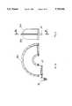
- FIG. 1shows, schematically, a plant 1 according to the invention for pasteurizing or sterilising substances in a liquid state in a discontinuous cycle.
- the plantincludes a first tubular element 2 for the rapid heating of the product, made up of a plurality of small-diameter, cylindrical tubular sections 2a, substantially the same as each other and of an end tubular section 2b, with curved axis and angular development up to 180° and of a diameter substantially equal to that of the cylindrical tubular sections 2a, the said end section 2b connecting the said first tubular element 2 and a second tubular element 3 in which the phase of the maintenance of the final pasteurization or sterilisation temperature is carried out.
- the second tubular element 3similarly to the tubular element 2, is also made up of a plurality of small-diameter, cylindrical tubular sections 3a, which are substantially the same as each other, and of a end section 3b, tubular with curved axis and angular development up to 180°, which connects the second tubular element 3 to a third tubular element 4 in which cooling of the product after the pasteurization or sterilisation treatment is carried out.
- the third tubular element 4is made up of a plurality of smalldiameter cylindrical tubular sections 4a, substantially the same as each other.
- the products to be sterilised or pasteurized, packaged in sealed containers 49 (FIG. 9) of materials transparent to microwaves,are inserted in the plant 1 and removed from it by means of a first conveyor device 5 and a second conveyor device 6, for example a conveyor belt.
- the first conveyor device 5inserts the containers 49 in an entrance element 7, which on the inside has opening and airtight closing devices (not shown), which is communicating with the first cylindrical, tubular section 2a of the first tubular element 2.
- the second conveyor device 6collects the containers 49 from an exit element 10, which on the inside has opening and airtight closing devices (not shown), which is communicating with the last cylindrical, tubular section 4a of the third tubular element 4.
- a first connecting element 8is inserted between the end section 2b of the first tubular element 2 and the second tubular element 3 of plant 1
- a second connecting element 9is inserted between the end section 3b of the second tubular element 3 and the third tubular element 4 of plant 1.
- the elements 8 and 9, which are analogous to the entrance element 7 and to the exit element 10,are both have opening and airtight closing devices.
- curved tubular sections 2b, 3bmay be omitted, if the space available for the installation of the plant 1 enables the tubular elements 2, 3 and 4 to be positioned in line.
- FIG. 2shows, schematically, a plant 10a for pasteurizing or sterilising solid, soft or semiliquid products in a discontinuous cycle, consisting of four tubular elements.
- the plant of FIG. 2consists of a first tubular element 11 for the rapid heating of the product, made up of a plurality of smalldiameter, cylindrical, tubular sections 11a, substantially of the same as each other and a tubular end section 11b with a curved axis and angular development up to 180°, which connects said first tubular element 11 and a second tubular element 12, in which the final heating phase and the equalisation of the final treatment temperature of the product is carried out.
- the said second tubular elementis also composed of a plurality of small-diameter cylindrical, tubular sections 12a, substantially the same as each other, and of one tubular end section 12b with curved axis and angular development up to 180° and a third tubular element 13, for the maintenance of the final treatment temperature.
- the said tubular element 13is also composed of a plurality of small-diameter, cylindrical tubular sections 13a, substantially the same as each other and of a tubular end section 13b with curved axis and angular development up to 180°, which connects said third tubular element to a fourth tubular element 14 in which the cooling of the product takes place after it has been treated.
- Said fourth tubular element 14is composed of a plurality of small-diameter, cylindrical tubular elements, substantially the same as each other.
- the products to be sterilised or pasteurized, packaged in sealed containers 49 of material transparent to microwaves,are inserted in the plant 10a and removed from it by means of a first conveyor device 15 and a second conveyor device 16, for example a conveyor belt.
- the first conveyor device 15inserts the containers 49 in an entrance element 17, which on the inside has opening and airtight closing device (not shown), which is communicating with the first cylindrical, tubular section 11 a and the first tubular element 11.
- the second conveyor device 16collects the containers 49 from an exiting element 21, which on the inside has opening and airtight closing device (not shown), which is communicating with the last cylindrical tubular section 14a of the fourth tubular element 14.
- a first connecting element 18is inserted between the end section 11b of the first tubular element 11 and the second tubular element 12 of the plant 10a
- a second connecting element 19is inserted between the end section 12b of the second tubular element 12 and the third tubular element 13 of the plant 10a
- a third connecting element 20is inserted between the end section 13b of the third tubular element 13 and the fourth tubular element 14 of the plant 10a.
- curved tubular sections 11b, 12b, 13bmay be omitted if the space available for the installation of the plant 10a allows the tubular elements to be positioned in line.
- FIG. 3shows a plant 22 for the treatment of substances in a liquid state in a continuous cycle, consisting of two or more plants 1, side-by-side or superimposed, fed in parallel by a conveyor belt 23, by means of a switching device 24.
- FIG. 4shows a plant 25 for the treatment of solid, soft or semiliquid substances in a continuous cycle, consisting of two or more plants 10a , side-by-side or superimposed, fed by a conveyor belt 23, by means of a switching device 24.
- FIGS. 5 and 6show one of the end sections 2b, 3b ; 11b, 12b, 13b which connects the tubular elements 2, 3, 4; 11, 12, 13, 14 of plants 1 or 10a.
- Each one of the said end sectionsconsists of two flanged halves 26a, 26b, inside which is placed a conveyor device 27, for example a conveyor belt, driven by a motor reducer 28, for transporting containers 49 with the product to be pasteurized or sterilised.
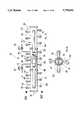
- FIG. 7shows a first tubular element 11 of the plant 10a for pasteurizing or sterilising solid, soft or semiliquid products, in which the first phase of the of the pasteurization or sterilisation treatment is carried out, consisting of the rapid heating of the products, at progressively increasing pressure in function of the temperature.
- a number of microwave generators 29, for example magnetronare arranged in staggered longitudinal or circumferential rows, having wave guides 30 that, preferably, have a rectangular section.
- the wave guides of the microwave generators 29 of the same roware preferably alternatively rotated 90° with respect to each other.
- the containers 49 containing the products to be pasteurized or sterilisedare conveyed through the said first tubular element 11 by means of a conveyor device 31, for example a conveyor belt, made in microwave transparent material to allow the products to be radiated from below, through the base of the containers 49.
- the tubular element 11also has a pair of air cooling ducts 32, which communicate with the inside of the tubular sections 11a, each duct 32 having a heat exchanger 33 and a fan 34.
- the exchanger 33is supplied with a primary refrigerating fluid, for example, glycol, by means of a supply tube 35 and a discharge tube 36.
- a primary refrigerating fluidfor example, glycol
- the flow of the refrigerating fluid in the exchangeris controlled by means of a three-way valve 37.
- the inside of the tubular element 11is pressurised, with progressively increasing pressure, in function of the temperature reached by the product, by means of compressed air introduced through a tube 38 with a valve 39, preferably pneumatically operated, to modulate the pressure inside the said tubular element 11.
- the valve 39is linked to a pressure transducer 40, through a PLC (not shown).
- a discharge tube 41 with a discharge valve 42for example pneumatically operated, which permits the slow or rapid decompression of the tubular element 11.
- the tubular element 11also has a pressure limiting safety valve 43, a pressure gauge 44 to check the pressure, two safety manostats 45 and 46, respectively for minimum and maximum pressure, which control, through the PLC, the discharge valve 42, and a temperature sensor 47 which is linked to the valve 37 through the PLC.
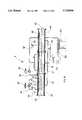
- FIG. 9shows a first tubular element 2 of the plant of FIG. 1 for the sterilisation of liquid products in which a first phase of rapid heating of the product is carried out by means of pressurised water vapour, which is introduced into said first tubular element 2 by means of an inlet pipe 50 with a valve 51, for example pneumatically operated, to control the flow of the vapour, said valve 51 being linked through the PLC to a temperature sensor 47.
- the vapour introduced through the inlet pipe 50is distributed inside the tubular element 2 by means of a tube 52 that has nebulizer nozzles 53.
- the containers 49 containing the products to be pasteurized or sterilisedare conveyed through said first tubular element 2 by means of a conveyor device 48, for example a conveyor belt.
- the inside of the tubular element 2is pressurised, with progressively increasing pressure, in function of the temperature reached by the product, by means of compressed air supplied through a tube 38 with a valve 39, preferably pneumatically operated, to vary the pressure inside said tubular element 2.
- the valve 39is linked to a pressure transducer 40, through a PLC (not shown).
- a discharge pipe 41equipped with a discharge valve 42, for example pneumatically operated, which enables the slow or rapid decompression of the tubular element 2.
- tubular element 2has a pressure limiting safety valve 43 a pressure gauge 44 to check the pressure, two safety manostats 45 and 46, respectively for minimum and maximum pressure, which control the discharge valve 42 through the PLC, and a temperature sensor 47.
- FIG. 10shows a second tubular element 3 of the plant 1 for pasteurizing or sterilising liquid products or a first version of the second tubular element 12 of the plant 10a for pasteurizing or sterilising solid, semiliquid or soft products.
- the second phase of the pasteurization or sterilisation treatmentis carried out, consisting of the equalisation of the temperature reached by the products at the end of the first rapid heating phase, in the case of solid, semiliquid or soft products, and of the maintenance of the pasteurization or sterilisation temperature phase, in the case of liquid products.
- a number of microwave generators 29, for example magnetronare arranged in staggered longitudinal or circumferential rows, having wave guides 30 that, preferably, have a rectangular section.
- the wave guides of the microwave generators 29 of the same roware preferably alternatively rotated 90° with respect to each other.
- the containers 49 containing the products to be pasteurized or sterilisedare conveyed through the said second tubular element 3, 12 by means of a conveyor device 31, for example a conveyor belt, made in microwave transparent material to allow the products to be radiated from below, through the base of the containers 49.
- a conveyor device 31for example a conveyor belt, made in microwave transparent material to allow the products to be radiated from below, through the base of the containers 49.
- the inside of the tubular element 3, 12is pressurised, with progressively increasing pressure, in function of the temperature reached by the product, by means of compressed air introduced through a tube 38 with a valve 39, preferably pneumatically operated, to modulate the pressure inside the said tubular element 3, 12.
- the valve 39is linked to a pressure transducer 40, through a PLC (not shown).
- a discharge tube 41With a discharge valve 42, for example pneumatically operated, which permits a slow or rapid decompression of the tubular element 3, 12.
- the tubular element 11also has a pressure limiting safety valve 43, a pressure gauge 44 to check the pressure, two safety manostats 45 and 46, respectively for minimum and maximum pressure, which control the discharge valve 42 through the PLC, and a temperature sensor 47.
- the equalisation of the temperature in the throughout the entire mass of products subjected to the pasteurization or sterilisation treatmentis achieved by means of pressurised water vapour which is introduced into the said second tubular element 3, 12 through inlet pipe 50 with a valve 51, for example pneumatically operated, to control the flow of the vapour, said valve 51 being linked through the PLC to a temperature sensor 47.
- a valve 51for example pneumatically operated
- the vapour introduced through the inlet pipe 50is distributed inside the tubular element 3, 12 by means of a tube 52 that has nebulizer nozzles 53.
- FIGS. 11 and 12show a second version of the second tubular element 12 of plant 10a for pasteurizing or sterilising solid, semiliquid or soft products.
- tubular element 12differs from the first version shown in FIG. 10 in that the temperature equalisation throughout the entire mass of products subjected to the pasteurization or sterilisation treatment is achieved by means of pressurised hot air.
- tubular element 12has a pair of channels 32a that are communicating with the inside of tubular sections 12a, each channel 32a having fan 34 and electric radiator 55.
- FIGS. 13 and 14show a third tubular element 13 of plant 10a for pasteurizing or sterilising solid, semiliquid and soft products, inside which the third phase of the pasteurization or sterilisation procedure is carried out, consisting of maintaining the temperature of the products at the value reached at he end of the first two phases for a predetermined length of time.
- the structure of the third tubular elementis essentially identical to that of the second tubular element 12, the only difference being possibly in the number and power rating of the microwave generator elements 29, in that the thermal power required in the said third phase of the pasteurization or sterilisation procedure is lower than that required for the second phase.
- FIGS. 15 and 16show a second version of the said third tubular element 13 in which the temperature is maintained using only hot air.
- the said second version of the said third tubular elementdiffers from the first version, shown in FIGS. 13 and 14, in that it does not have any microwave generator elements.
- FIG. 17a third tubular element 4 of plant 2 for pasteurizing or sterilising liquid products, or a first version of a fourth tubular element 14 of plant 10a for pasteurizing or sterilising solid, semiliquid or soft products, in which the products are cooled at the end of the pasteurization or sterilisation procedure treatment.
- the coolingis carried out using water which is sprinkled on containers 49 from a cooling water distribution tube 56, supplied by a pipe 57 originating at a refrigerating heat exchanger 58.
- the refrigerator 58is supplied by a feed pump 59 which takes the water to be cooled from a reservoir 60 which collects the cooling water used in tubular element 4, 14 by means of collection pipes 61.
- FIGS. 18 and 19show a second version of the fourth tubular element 14 of plant 10a in which the products are cooled by means of refrigerated air introduced into tubular element 14 through a pair of channels 32 each of which is has a heat exchanger 33 and fan 34.
- the exchanger 33is supplied with a primary refrigerating fluid, for example ethylene glycol, by means of a supply tube 35 and a discharge tube 36.
- a primary refrigerating fluidfor example ethylene glycol
- the flow of the refrigerating fluid in the exchangeris controlled by means of a three-way valve 37.
- All the tubular elements of the plant 1 or of the plant 10a that have microwave generator elementshave a screening element 62 to screen the sides of the packages 49 from the microwaves with a view to preventing the products contained in them from overheating in the areas adjacent to the said sides.
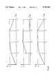
- FIG. 20there are three diagrams that show the variation, in function of time, of the ambient pressure pc, the ambient temperature T c and the temperature of the product T p during the three phases of the pasteurization or sterilisation treatment of a liquid product.
- the ambient pressure P c and the ambient temperature T care the pressure and the temperature inside the tubular elements 2, 3 and 4 of plant 1.
- the times t 1 , t 2 , t 3represent the duration of the various phases of the treatment; T s and P s are, respectively, the pasteurizing, or sterilising, temperature and pressure.
- FIG. 21there are three diagrams, similar to those in FIG. 20, that show the variation, in function of time, of the ambient pressure P c , the ambient temperature T c and the temperature of the product T p during the four phases of the pasteurization or sterilisation treatment of solid, semisolid products.
- the ambient pressure pc and the ambient temperature T care the pressure and the temperature inside the tubular elements 11, 12, 13 and 14 of plant 10a.
- the times t 1 , t 2 , t 3represent the duration of the various phases of the treatment; T s and p s are, respectively, the pasteurizing, or sterilising, temperature and pressure.
- Operation of the plant 10a for pasteurizing or sterilising solid, semiliquid or soft productsis as follows: the packages 49 containing the products to be subjected to the pasteurization or sterilisation treatment are inserted in the first tubular element 11 of the plant by conveyor device 15 through the entry element 17 and transported inside the said first tubular element by the conveyor device 31 until the sections 11 a and 11b of tubular element are completely filled.
- the first phase of the pasteurization or sterilisation treatmentis started, consisting of the rapid heating of the product, activating magnetrons 29 and refrigerator 33, whilst the containers of the products are made to oscillate back and forth by the conveyor device 31.
- the refrigerator 33maintains the ambient temperature inside the said first tubular element 11 at a value of between 5° C. to 15° C. depending on the type of product being treated: this so as to avoid overheating the product, with a nonuniform absorption of the microwaves, in particular on the outside surface of the product itself.
- the pressure inside the said first tubular element 11 of the plantis increased, with a substantially linear progression, by introducing compressed air into the tubular element through the control valve 39, for example pneumatically operated, in such a way that the pressure corresponds substantially, at every moment, to the vapour pressure of water at the temperature reached by the product.
- the second tubular element 12a of plant 11is pressurised to a point where the pressure inside it corresponds to the vapour pressure of water at the temperature reached by the product at the end of the first phase.
- the electric radiator 55is switched on, which, with fan 34 sends hot air inside the tubular element 12a until the temperature inside it reaches a value corresponding to that reached by the product at the end of the said first phase.
- the magnetrons 29 of the said second tubular elementare switched on, while, at the same time, the pressure inside the first tubular element 11 is reduced to atmospheric pressure discharging the pressurised air through valve 42, for example pneumatically operated.
- the productis subjected to the second phase of the sterilisation or pasteurization constment consisting of a further heating using microwaves and pressurised water vapour, or hot air, at a slightly higher temperature, for example by 5° C., than sterilising or pasteurizing temperature, the vapour being introduced by means of nozzles 53 supplied by inlet tubing 50, through a flow control valve 52, for example pneumatically operated.
- the heating of the product in the second phase of the treatmentoccurs with a lower temperature gradient than the temperature gradient in the first phase, the pressure inside the second tubular element 12 being gradually increased so that it corresponds substantially, at every moment, to the vapour pressure of water at the temperature reached by the product.
- the first tubular element 11is loaded with another series of containers and the first phase of the treatment of the product is started.
- the third tubular element 13is prepared for receiving the product subjected to the second phase of the treatment bringing the pressure inside it, by introducing compressed air through control valve 39, to a value substantially the same as the pressure reached in the second tubular element 12 at the end of the second phase of the treatment; at the same time the temperature of the third tubular element 13 is also brought up to a value corresponding substantially to that reached by the product at the end of the second phase of the treatment, heating the air inside the said third tubular element 13 using electric radiator 55 and circulating it by means of fan 34 and channels 32.
- the containers 49are made to pass through into the third tubular element 13 of the plant, through connecting element 19, by means of conveyor devices 31 and 27 of the second tubular element 12 and conveyor device 31, or 48, of the third tubular element 13 of the plant.
- the third phase of the pasteurizing or sterilising treatment of the productis carried out, consisting of maintaining the pasteurizing or sterilising temperature for the time required to kill 100% of the microorganisms present in the product.
- the third phase of the treatmentis carried out at a constant pressure and the maintenance of the pasteurizing or sterilising temperature can be achieved with microwaves and hot air (FIGS. 13, 14), with microwave radiation of considerably reduced power with respect to that used in the second phase, or only with hot air (FIGS. 15, 16).
- the containers of the product previously introduced into the first tubular element 11 and subjected to the first phase of the pasteurization or sterilisation treatmentare transferred to the second tubular element 12 where they are to be subjected to the second phase of the pasteurization or sterilisation treatment and the first tubular element 11 is loaded with another series of containers after the pressure inside it has been reduced to atmospheric pressure, so as to start the first phase of the treatment of the product.
- the fourth tubular elementis pressurised to a value equal to that of the third tubular element 13 and heated to a temperature equal to that of the third tubular element 13 of the plant.
- the containers in the third tubular element 13 of the plantare transferred to the fourth tubular element 14 where they are subjected to the fourth and final phase of the treatment: the transfer is achieved with conveyor devices 27 and 31, or 48, of the third tubular element 13 and the conveyor device 48 of the fourth tubular element 14.
- the containers in the second tubular element 12are transferred to the third tubular element 13
- the containers in the first tubular element 11are transferred to the second tubular element 12 and the first tubular element 11 is filled with another series of containers in accordance with the procedures described previously.
- the fourth phase of the pasteurization or sterilisation treatmentconsists of the progressive cooling of containers 49 and of the products contained in them with a simultaneous progressive reduction in the pressure inside the said fourth tubular element 14 of the plant down to ambient temperature and pressure.
- the coolingis carried out with refrigerated water (FIG. 17), sprinkled on the containers 49 by a distribution pipe 56, or with refrigerated air (FIG. 18), the pressure inside the said fourth tubular element 14 being progressively reduced, discharging pressurised air through discharge tube 41 and discharge valve 42, for example pneumatically operated.
- the pressureis reduced in such a way that the value of the pressure corresponds, at every moment, to the vapour pressure of water at the temperature reached by the product.
- the pressure in the fourth tubular element 14is restored to the value at the start of the cooling and the containers 49 in the first three tubular elements are transferred to the next tubular element and the first tubular element 11 is loaded with another series of containers.
- conveyor device 23for example a conveyor belt, having a switching device 24, to transfer the containers 49 onto the conveyor devices 15 feeding the various plants it is possible achieve operation in a continuous cycle, that is, without ever interrupting the flow of containers arriving from conveyor device 23.
- the pasteurization or sterilisation treatment for liquid foodstuffscan only include three phases, that is, two heating phases of the product at different speeds and a cooling phase, as the pasteurization or sterilisation temperature equalisation phase is not required in that the convection currents set up within the liquid product during the heating phases brings about a satisfactory equalisation of the temperature throughout the mass of the product.
- the heating and cooling phases of the pasteurization or sterilisation treatment of foodstuffs in the liquid stateare carried out in an analogous way to that already described for solid products, apart from in the rapid heating phase, in which, for liquid products, the tubular element of the plant in which the said rapid heating takes place does not need to be refrigerated as there is no risk of the product overheating locally or on the surface due to the internal convective currents.
- the heatingcan, thereby, be carried out in a plant 1 in which the product in the first tubular element 2 is heated by means of pressurised vapour (FIG. 9) fed into the tubular element itself through pipe 52 having nebulizer nozzles 53 supplied by tubing 50, through flow control valve 51, for example pneumatically operated.
- pressurised vapourFIG. 9
- the second heating phasecan be carried out with microwaves and vapour, or microwaves and hot air, with the same procedure already described for the sterilisation or pasteurization of solid, soft or semiliquid products.
- the cooling phaseis also carried in an analogous way to that already described for solid, soft or semiliquid products.
Landscapes
- Life Sciences & Earth Sciences (AREA)
- Engineering & Computer Science (AREA)
- Wood Science & Technology (AREA)
- Zoology (AREA)
- Chemical & Material Sciences (AREA)
- Food Science & Technology (AREA)
- Polymers & Plastics (AREA)
- Food Preservation Except Freezing, Refrigeration, And Drying (AREA)
Abstract
Description
Claims (30)
Priority Applications (1)
| Application Number | Priority Date | Filing Date | Title |
|---|---|---|---|
| US08/756,188US5750966A (en) | 1993-12-09 | 1996-11-25 | Plant for pasteurizing or sterilising solid or liquid food products using microwaves |
Applications Claiming Priority (4)
| Application Number | Priority Date | Filing Date | Title |
|---|---|---|---|
| ITMO930155AIT1262686B (en) | 1993-12-09 | 1993-12-09 | Method and equipment for the pasteurisation or sterilisation of solid or liquid food products using microwaves |
| ITMO93A0155 | 1993-12-09 | ||
| US35317494A | 1994-12-08 | 1994-12-08 | |
| US08/756,188US5750966A (en) | 1993-12-09 | 1996-11-25 | Plant for pasteurizing or sterilising solid or liquid food products using microwaves |
Related Parent Applications (1)
| Application Number | Title | Priority Date | Filing Date |
|---|---|---|---|
| US35317494AContinuation | 1993-12-09 | 1994-12-08 |
Publications (1)
| Publication Number | Publication Date |
|---|---|
| US5750966Atrue US5750966A (en) | 1998-05-12 |
Family
ID=11385512
Family Applications (1)
| Application Number | Title | Priority Date | Filing Date |
|---|---|---|---|
| US08/756,188Expired - LifetimeUS5750966A (en) | 1993-12-09 | 1996-11-25 | Plant for pasteurizing or sterilising solid or liquid food products using microwaves |
Country Status (2)
| Country | Link |
|---|---|
| US (1) | US5750966A (en) |
| IT (1) | IT1262686B (en) |
Cited By (23)
| Publication number | Priority date | Publication date | Assignee | Title |
|---|---|---|---|---|
| US6014212A (en)* | 1997-08-08 | 2000-01-11 | Pfizer Inc. | Method and apparatus for spectrophotometrically analysing characteristics of a tablet |
| KR20020059318A (en)* | 2002-06-21 | 2002-07-12 | 주식회사 삶과기술 | A fluid sterillizer |
| US20040131519A1 (en)* | 2002-10-18 | 2004-07-08 | Pagotto Amedeo | Tunnel for conditioning of products, especially for sterilization of food in prepackaged containers |
| US20090181139A1 (en)* | 2005-04-12 | 2009-07-16 | Mohammed Mehid Farid | Pressure Assisted Thermal Sterilisation or Pasteurisation Method and Apparatus |
| US20100071475A1 (en)* | 2008-09-24 | 2010-03-25 | Krones Ag | Device for monitoring the flow of water vapor |
| US20100126988A1 (en)* | 2008-11-24 | 2010-05-27 | Mackay Jeffrey H | Apparatus and method for mass sterilization and pasteurization of food products |
| US20130118969A1 (en)* | 2011-11-16 | 2013-05-16 | Chun Il Koh | Food waste disposal system including BOD reduction apparatus |
| US9066376B2 (en) | 2012-03-14 | 2015-06-23 | Microwave Materials Technologies, Inc. | Locking gate device |
| WO2016044571A1 (en)* | 2014-09-17 | 2016-03-24 | Kraft Foods Group Brands Llc | A microwave retort system, a process for heating food products using a microwave retort system, and food products formulated for microwave retort |
| US20160183333A1 (en)* | 2014-12-17 | 2016-06-23 | Campbell Soup Company | Electromagnetic wave food processing system and methods |
| EP3075397A1 (en)* | 2015-04-03 | 2016-10-05 | Enbio Technology Spolka z o.o. | The method and system for microwave sterilisation of liquid media |
| WO2016161330A1 (en) | 2015-04-01 | 2016-10-06 | Printpack Illinois, Inc. | Multi-ply films for sterilization or pasteurization processes |
| WO2018063469A1 (en) | 2016-09-28 | 2018-04-05 | Printpack Illinois, Inc. | Multi-ply structures, packages, and methods of sterilization |
| WO2018063468A1 (en) | 2016-09-28 | 2018-04-05 | Printpack Illinois, Inc. | Microwaved multi-ply structures, microwaved packages, and methods of sterilization |
| GB2573331A (en)* | 2018-05-04 | 2019-11-06 | Donal Oflynn | Thermal processing apparatus |
| WO2020006481A1 (en)* | 2018-06-29 | 2020-01-02 | 915 Labs, LLC | Modular electromagnetic heating system |
| US10966293B2 (en) | 2017-04-17 | 2021-03-30 | 915 Labs, LLC | Microwave-assisted sterilization and pasteurization system using synergistic packaging, carrier and launcher configurations |
| US11032879B2 (en) | 2017-03-15 | 2021-06-08 | 915 Labs, Inc. | Energy control elements for improved microwave heating of packaged articles |
| US11129243B2 (en) | 2017-03-15 | 2021-09-21 | 915 Labs, Inc. | Multi-pass microwave heating system |
| IT202000008830A1 (en)* | 2020-04-23 | 2021-10-23 | M I T Srl | TUNNEL EQUIPMENT FOR CONTINUOUS AND AUTOMATIC MICROWAVE TREATMENT OF VARIOUS PRODUCTS, WITH SHIELDING DEVICES AGAINST MICROWAVES |
| US20220212954A1 (en)* | 2019-06-24 | 2022-07-07 | Dhf America, Llc. | System and method of decomposing fluidic product having particles |
| WO2023233089A1 (en)* | 2022-06-03 | 2023-12-07 | Sairem Societe Pour L'application Industrielle De La Recherche En Electronique Et Micro Ondes | Microwave pasteurisation facility incorporating a ventilation cooling system |
| DE102024109254A1 (en)* | 2024-04-03 | 2025-10-09 | Krones Aktiengesellschaft | Thermal container treatment machine, filling system and method for thermally treating containers filled with product and sealed with the thermal container treatment machine |
Families Citing this family (1)
| Publication number | Priority date | Publication date | Assignee | Title |
|---|---|---|---|---|
| AUPP346998A0 (en)* | 1998-05-12 | 1998-06-04 | Davis, Jeffree Timothy | Method and apparatus for processing foodstuffs |
Citations (23)
| Publication number | Priority date | Publication date | Assignee | Title |
|---|---|---|---|---|
| FR1351489A (en)* | 1962-12-11 | 1964-02-07 | Technoexp | Method and equipment for heating and sterilizing products in non-metallic packaging with high frequency energy |
| US3335253A (en)* | 1963-09-11 | 1967-08-08 | Cryodry Corp | Microwave heating of substances under hydrostatic pressure |
| FR1571833A (en)* | 1967-12-05 | 1969-06-20 | ||
| US3611582A (en)* | 1969-11-07 | 1971-10-12 | Canadian Patents Dev | Microwave package for control of moisture content and insect infestations of grain |
| FR2107422A5 (en)* | 1970-09-08 | 1972-05-05 | Alfa Laval Ab | |
| FR2107423A5 (en)* | 1970-09-08 | 1972-05-05 | Alfa Laval Ab | |
| US3889009A (en)* | 1972-07-31 | 1975-06-10 | Samuel P Lipoma | Method for continuous electromagnetic sterilization of food in a pressure zone |
| US3961569A (en)* | 1974-08-15 | 1976-06-08 | The United States Of America As Represented By The Secretary Of The Army | Apparatus for continuous microwave sterilization of food in pouches |
| SU584703A1 (en)* | 1976-08-16 | 1980-02-15 | Предприятие П/Я В-2058 | Superhighfrequency device for drying granulated dielectric materials |
| FR2432845A1 (en)* | 1978-08-07 | 1980-03-07 | Bach Hannelore | METHOD AND DEVICE FOR THE HEAT TREATMENT OF FOOD PRODUCTS |
| US4294858A (en)* | 1980-03-27 | 1981-10-13 | Moule Rex E | Self-surfaced meat product manufacturing method and apparatus |
| US4358652A (en)* | 1978-12-21 | 1982-11-09 | Kaarup Darrell R | Fluid heater apparatus |
| US4388511A (en)* | 1980-05-23 | 1983-06-14 | Jung Gmbh | Microwave heating apparatus for circulable media |
| FR2547732A1 (en)* | 1983-06-21 | 1984-12-28 | Lequeux Sa | Method and installation for heat sterilisation of liquid substances contained in hermetically sealed containers |
| US4714812A (en)* | 1985-05-08 | 1987-12-22 | John F. Woodhead, III | Apparatus and method for processing dielectric materials with microwave energy |
| EP0344408A1 (en)* | 1988-06-03 | 1989-12-06 | BARILLA G. e R. F.lli - Società per Azioni | A method for heat stabilizing pre-packaged food products on a continuous basis |
| EP0347623A1 (en)* | 1988-06-07 | 1989-12-27 | BARILLA G. e R. F.lli - Società per Azioni | A method of pasteurizing or sterilizing foodstuffs utilizing microwaves, and an oven for the implementation of such a method |
| EP0350564A1 (en)* | 1988-07-13 | 1990-01-17 | BARILLA G. e R. F.lli - Società per Azioni | An apparatus for thermally stabilizing pre-packaged food articles |
| US4962298A (en)* | 1988-07-18 | 1990-10-09 | Barilla G.E.R. F.LII-Societa per Azoni | Machine for thermally treating and sterilizing pre-packaged food articles by means of microwaves |
| WO1992002150A1 (en)* | 1990-08-03 | 1992-02-20 | Kansas State University Research Foundation | Heat processing of a product |
| US5122633A (en)* | 1989-06-07 | 1992-06-16 | Wolfgang Moshammer | Method and apparatus for radiation microwave energy into material containing water or mixed with water |
| US5283033A (en)* | 1991-11-29 | 1994-02-01 | Advanced Retort Systems, Inc. | Process for sterilizing the contents of a sealed deformable package |
| NL9201232A (en)* | 1992-07-09 | 1994-02-01 | Stork Amsterdam | Method and device for subjecting a packaged product, in particular a foodstuff, to a heat treatment, such as sterilization |
- 1993
- 1993-12-09ITITMO930155Apatent/IT1262686B/enactiveIP Right Grant
- 1996
- 1996-11-25USUS08/756,188patent/US5750966A/ennot_activeExpired - Lifetime
Patent Citations (25)
| Publication number | Priority date | Publication date | Assignee | Title |
|---|---|---|---|---|
| FR1351489A (en)* | 1962-12-11 | 1964-02-07 | Technoexp | Method and equipment for heating and sterilizing products in non-metallic packaging with high frequency energy |
| US3335253A (en)* | 1963-09-11 | 1967-08-08 | Cryodry Corp | Microwave heating of substances under hydrostatic pressure |
| FR1571833A (en)* | 1967-12-05 | 1969-06-20 | ||
| US3611582A (en)* | 1969-11-07 | 1971-10-12 | Canadian Patents Dev | Microwave package for control of moisture content and insect infestations of grain |
| FR2107422A5 (en)* | 1970-09-08 | 1972-05-05 | Alfa Laval Ab | |
| FR2107423A5 (en)* | 1970-09-08 | 1972-05-05 | Alfa Laval Ab | |
| US3889009A (en)* | 1972-07-31 | 1975-06-10 | Samuel P Lipoma | Method for continuous electromagnetic sterilization of food in a pressure zone |
| US3961569A (en)* | 1974-08-15 | 1976-06-08 | The United States Of America As Represented By The Secretary Of The Army | Apparatus for continuous microwave sterilization of food in pouches |
| SU584703A1 (en)* | 1976-08-16 | 1980-02-15 | Предприятие П/Я В-2058 | Superhighfrequency device for drying granulated dielectric materials |
| FR2432845A1 (en)* | 1978-08-07 | 1980-03-07 | Bach Hannelore | METHOD AND DEVICE FOR THE HEAT TREATMENT OF FOOD PRODUCTS |
| US4358652A (en)* | 1978-12-21 | 1982-11-09 | Kaarup Darrell R | Fluid heater apparatus |
| US4294858A (en)* | 1980-03-27 | 1981-10-13 | Moule Rex E | Self-surfaced meat product manufacturing method and apparatus |
| US4388511A (en)* | 1980-05-23 | 1983-06-14 | Jung Gmbh | Microwave heating apparatus for circulable media |
| FR2547732A1 (en)* | 1983-06-21 | 1984-12-28 | Lequeux Sa | Method and installation for heat sterilisation of liquid substances contained in hermetically sealed containers |
| US4714812A (en)* | 1985-05-08 | 1987-12-22 | John F. Woodhead, III | Apparatus and method for processing dielectric materials with microwave energy |
| EP0344408A1 (en)* | 1988-06-03 | 1989-12-06 | BARILLA G. e R. F.lli - Società per Azioni | A method for heat stabilizing pre-packaged food products on a continuous basis |
| EP0347623A1 (en)* | 1988-06-07 | 1989-12-27 | BARILLA G. e R. F.lli - Società per Azioni | A method of pasteurizing or sterilizing foodstuffs utilizing microwaves, and an oven for the implementation of such a method |
| US5066503A (en)* | 1988-06-07 | 1991-11-19 | Officine Meccaniche Attrezzature Per Ceramiche | Method of pasteurizing or sterilizing foodstuffs utilizing microwaves |
| US5074200A (en)* | 1988-06-07 | 1991-12-24 | Officine Meccaniche Attrezzature Per Ceramiche | System for pasteurizing or sterilizing foodstuffs utilizing microwaves |
| EP0350564A1 (en)* | 1988-07-13 | 1990-01-17 | BARILLA G. e R. F.lli - Società per Azioni | An apparatus for thermally stabilizing pre-packaged food articles |
| US4962298A (en)* | 1988-07-18 | 1990-10-09 | Barilla G.E.R. F.LII-Societa per Azoni | Machine for thermally treating and sterilizing pre-packaged food articles by means of microwaves |
| US5122633A (en)* | 1989-06-07 | 1992-06-16 | Wolfgang Moshammer | Method and apparatus for radiation microwave energy into material containing water or mixed with water |
| WO1992002150A1 (en)* | 1990-08-03 | 1992-02-20 | Kansas State University Research Foundation | Heat processing of a product |
| US5283033A (en)* | 1991-11-29 | 1994-02-01 | Advanced Retort Systems, Inc. | Process for sterilizing the contents of a sealed deformable package |
| NL9201232A (en)* | 1992-07-09 | 1994-02-01 | Stork Amsterdam | Method and device for subjecting a packaged product, in particular a foodstuff, to a heat treatment, such as sterilization |
Cited By (50)
| Publication number | Priority date | Publication date | Assignee | Title |
|---|---|---|---|---|
| US6014212A (en)* | 1997-08-08 | 2000-01-11 | Pfizer Inc. | Method and apparatus for spectrophotometrically analysing characteristics of a tablet |
| KR20020059318A (en)* | 2002-06-21 | 2002-07-12 | 주식회사 삶과기술 | A fluid sterillizer |
| US8372350B2 (en) | 2002-10-18 | 2013-02-12 | Pagotto Amedeo | Tunnel for conditioning of products, especially for sterilization of food in prepackaged containers |
| US20040131519A1 (en)* | 2002-10-18 | 2004-07-08 | Pagotto Amedeo | Tunnel for conditioning of products, especially for sterilization of food in prepackaged containers |
| US7993603B2 (en) | 2002-10-18 | 2011-08-09 | Pagotto Amedeo | Tunnel for conditioning of products, especially for sterilization of food in prepackaged containers |
| US9307784B2 (en) | 2002-10-18 | 2016-04-12 | Teo, Inc. | Tunnel for conditioning of products, especially for sterilization of food in prepackaged containers |
| WO2004036991A3 (en)* | 2002-10-18 | 2004-08-12 | Modofood Usa | Tunnel for conditioning of products, especially for sterilization of food in prepackaged containers |
| US20090181139A1 (en)* | 2005-04-12 | 2009-07-16 | Mohammed Mehid Farid | Pressure Assisted Thermal Sterilisation or Pasteurisation Method and Apparatus |
| US8678645B2 (en)* | 2008-09-24 | 2014-03-25 | Krones Ag | Device for monitoring the flow of water vapor |
| US20100071475A1 (en)* | 2008-09-24 | 2010-03-25 | Krones Ag | Device for monitoring the flow of water vapor |
| US8586899B2 (en)* | 2008-11-24 | 2013-11-19 | Jeffrey H. Mackay | Apparatus and method for mass sterilization and pasteurization of food products |
| US20100126988A1 (en)* | 2008-11-24 | 2010-05-27 | Mackay Jeffrey H | Apparatus and method for mass sterilization and pasteurization of food products |
| US20130118969A1 (en)* | 2011-11-16 | 2013-05-16 | Chun Il Koh | Food waste disposal system including BOD reduction apparatus |
| US9642195B2 (en) | 2012-03-14 | 2017-05-02 | Microwave Materials Technologies, Inc. | Enhanced microwave system utilizing tilted launchers |
| US9380650B2 (en) | 2012-03-14 | 2016-06-28 | 915 Labs, LLC | Multi-line microwave heating system with optimized launcher configuration |
| US9980325B2 (en) | 2012-03-14 | 2018-05-22 | Microwave Materials Technologies, Inc. | Enhanced control of a microwave heating system |
| US9179505B2 (en) | 2012-03-14 | 2015-11-03 | Microwave Materials Technologies, Inc. | Optimized motion and location of intense microwave fields within a heating system |
| US9357590B2 (en) | 2012-03-14 | 2016-05-31 | Microwave Materials Technologies, Inc. | Microwave heating system with enhanced temperature control |
| US9370052B2 (en) | 2012-03-14 | 2016-06-14 | Microwave Materials Technologies, Inc. | Optimized allocation of microwave power in multi-launcher systems |
| US9357589B2 (en) | 2012-03-14 | 2016-05-31 | Microwave Materials Technologies, Inc. | Commercial scale microwave heating system |
| US10448465B2 (en) | 2012-03-14 | 2019-10-15 | 915 Labs, LLC | Multi-line microwave heating system with optimized launcher configuration |
| US10798790B2 (en) | 2012-03-14 | 2020-10-06 | Microwave Materials Technologies, Inc. | Enhanced microwave system utilizing tilted launchers |
| US9271338B2 (en) | 2012-03-14 | 2016-02-23 | Microwave Materials Technologies, Inc. | Pressurized heating system with enhanced pressure locks |
| US9681500B2 (en) | 2012-03-14 | 2017-06-13 | Microwave Materials Technologies, Inc. | Enhanced microwave system employing inductive iris |
| US9066376B2 (en) | 2012-03-14 | 2015-06-23 | Microwave Materials Technologies, Inc. | Locking gate device |
| US9622298B2 (en) | 2012-03-14 | 2017-04-11 | Microwave Materials Technologies, Inc. | Microwave launchers providing enhanced field uniformity |
| US9301345B2 (en) | 2012-03-14 | 2016-03-29 | Microwave Materials Technologies, Inc. | Determination of a heating profile for a large-scale microwave heating system |
| CN106793812A (en)* | 2014-09-17 | 2017-05-31 | 卡夫食品集团品牌有限责任公司 | Microwave retort systems, methods for heating food products using microwave retort systems, and formulating food products for microwave retort |
| US20170245528A1 (en)* | 2014-09-17 | 2017-08-31 | Kraft Foods Group Brands Llc | A Microwave Retort System, A Process For Heating Food Products Using A Microwave Retort System, And Food Products Formulated For Microwave Retort |
| AU2015317664B2 (en)* | 2014-09-17 | 2019-07-25 | 915 Labs, LLC | A microwave retort system, a process for heating food products using a microwave retort system, and food products formulated for microwave retort |
| WO2016044571A1 (en)* | 2014-09-17 | 2016-03-24 | Kraft Foods Group Brands Llc | A microwave retort system, a process for heating food products using a microwave retort system, and food products formulated for microwave retort |
| US11229095B2 (en)* | 2014-12-17 | 2022-01-18 | Campbell Soup Company | Electromagnetic wave food processing system and methods |
| US20160183333A1 (en)* | 2014-12-17 | 2016-06-23 | Campbell Soup Company | Electromagnetic wave food processing system and methods |
| WO2016161330A1 (en) | 2015-04-01 | 2016-10-06 | Printpack Illinois, Inc. | Multi-ply films for sterilization or pasteurization processes |
| EP3075397A1 (en)* | 2015-04-03 | 2016-10-05 | Enbio Technology Spolka z o.o. | The method and system for microwave sterilisation of liquid media |
| WO2018063469A1 (en) | 2016-09-28 | 2018-04-05 | Printpack Illinois, Inc. | Multi-ply structures, packages, and methods of sterilization |
| WO2018063468A1 (en) | 2016-09-28 | 2018-04-05 | Printpack Illinois, Inc. | Microwaved multi-ply structures, microwaved packages, and methods of sterilization |
| US11129243B2 (en) | 2017-03-15 | 2021-09-21 | 915 Labs, Inc. | Multi-pass microwave heating system |
| US12309905B2 (en) | 2017-03-15 | 2025-05-20 | 915 Labs, Inc. | Energy control elements for improved microwave heating of packaged articles |
| US11032879B2 (en) | 2017-03-15 | 2021-06-08 | 915 Labs, Inc. | Energy control elements for improved microwave heating of packaged articles |
| US10966293B2 (en) | 2017-04-17 | 2021-03-30 | 915 Labs, LLC | Microwave-assisted sterilization and pasteurization system using synergistic packaging, carrier and launcher configurations |
| GB2573331A (en)* | 2018-05-04 | 2019-11-06 | Donal Oflynn | Thermal processing apparatus |
| WO2020006481A1 (en)* | 2018-06-29 | 2020-01-02 | 915 Labs, LLC | Modular electromagnetic heating system |
| US11511002B2 (en) | 2018-06-29 | 2022-11-29 | 915 Labs, Inc. | Modular electromagnetic heating system |
| US20220212954A1 (en)* | 2019-06-24 | 2022-07-07 | Dhf America, Llc. | System and method of decomposing fluidic product having particles |
| IT202000008830A1 (en)* | 2020-04-23 | 2021-10-23 | M I T Srl | TUNNEL EQUIPMENT FOR CONTINUOUS AND AUTOMATIC MICROWAVE TREATMENT OF VARIOUS PRODUCTS, WITH SHIELDING DEVICES AGAINST MICROWAVES |
| WO2023233089A1 (en)* | 2022-06-03 | 2023-12-07 | Sairem Societe Pour L'application Industrielle De La Recherche En Electronique Et Micro Ondes | Microwave pasteurisation facility incorporating a ventilation cooling system |
| FR3136145A1 (en)* | 2022-06-03 | 2023-12-08 | Sairem Societe Pour L'application Industrielle De La Recherche En Electronique Et Micro Ondes | Microwave pasteurization installation integrating a ventilation cooling system |
| US20250261658A1 (en)* | 2022-06-03 | 2025-08-21 | Sairem Societe Pour L'application Industrielle De La Recherche En Electronique Et Micro Ondes | Microwave pasteurization facility incorporating a ventilation cooling system |
| DE102024109254A1 (en)* | 2024-04-03 | 2025-10-09 | Krones Aktiengesellschaft | Thermal container treatment machine, filling system and method for thermally treating containers filled with product and sealed with the thermal container treatment machine |
Also Published As
| Publication number | Publication date |
|---|---|
| IT1262686B (en) | 1996-07-04 |
| ITMO930155A1 (en) | 1995-06-09 |
| ITMO930155A0 (en) | 1993-12-09 |
Similar Documents
| Publication | Publication Date | Title |
|---|---|---|
| US5750966A (en) | Plant for pasteurizing or sterilising solid or liquid food products using microwaves | |
| US5066503A (en) | Method of pasteurizing or sterilizing foodstuffs utilizing microwaves | |
| US4999471A (en) | Method for heat prepackaged food products using microwaves in a heated superatmospheric chamber | |
| EP2368405B1 (en) | Apparatus and method for mass sterilization and pasteurization of food products | |
| US5436432A (en) | Microwave autoclave apparatus | |
| KR20100015776A (en) | Sterilisation of liquids in hermetically closed vessels | |
| US5546854A (en) | Apparatus for heating and sterilizing food | |
| EP0983003B1 (en) | Inductive heating method and apparatus | |
| RO125073B1 (en) | Process and plant for the thermal processing of milk | |
| GB2071833A (en) | Vacuum drying apparatus | |
| US6436343B1 (en) | Method for the cold sterilization of a tunnel-type oven for pharmaceutical use, and oven for carrying out said method | |
| US5617781A (en) | Food sterilizing apparatus | |
| JP3754368B2 (en) | Continuous processing equipment | |
| USRE30310E (en) | Method and apparatus for treating heat-sensitive products | |
| EP0692197B1 (en) | Apparatus and method for sterilizing food | |
| EP0923871A1 (en) | Pasteurization-sterilization process for meat products and plant for implementing such process | |
| US3476574A (en) | Canning | |
| JPH0321147B2 (en) | ||
| JPS6021975Y2 (en) | Continuous pressurized microwave heating device | |
| US1588374A (en) | Apparatus for treating canned products | |
| GB2223926A (en) | Apparatus for, and method of, processing a food product | |
| KR200266155Y1 (en) | Sterilizer for Food or Drugs in Liquid or Semiliquid status by utiliging Microwave dielectric heating | |
| JPS608710Y2 (en) | Microwave heat sterilizer | |
| UA35432A (en) | Process of thermal processing of products in glass containers and a device for realization thereof | |
| JP2001253415A (en) | Continuous processing method and continuous processing device |
Legal Events
| Date | Code | Title | Description |
|---|---|---|---|
| STCF | Information on status: patent grant | Free format text:PATENTED CASE | |
| FPAY | Fee payment | Year of fee payment:4 | |
| SULP | Surcharge for late payment | ||
| REMI | Maintenance fee reminder mailed | ||
| AS | Assignment | Owner name:INDUSTRIAL MICROWAVE SYSTEMS, L.L.C., NORTH CAROLI Free format text:ASSIGNMENT OF ASSIGNORS INTEREST;ASSIGNOR:CLASSICA MICROWAVE TECHNOLOGIES, INC. AND CLASSICA GROUP, INC. BY ROBERT B. WASSERMAN, TRUSTEE IN US BANKRUPTCY COURT, DISTRICT OF NEW JERSEY;REEL/FRAME:014972/0769 Effective date:20040610 | |
| FEPP | Fee payment procedure | Free format text:PAT HOLDER NO LONGER CLAIMS SMALL ENTITY STATUS, ENTITY STATUS SET TO UNDISCOUNTED (ORIGINAL EVENT CODE: STOL); ENTITY STATUS OF PATENT OWNER: LARGE ENTITY | |
| REFU | Refund | Free format text:REFUND - PAYMENT OF MAINTENANCE FEE, 8TH YR, SMALL ENTITY (ORIGINAL EVENT CODE: R2552); ENTITY STATUS OF PATENT OWNER: LARGE ENTITY | |
| FPAY | Fee payment | Year of fee payment:8 | |
| AS | Assignment | Owner name:CLASSICA MICROWAVE TECHNOLOGIES, INC, NEW JERSEY Free format text:AGREEMENT TO WAIVE CERTAIN CLAIMS AND TO TRANSFER CERTAIN PROPERTY, INCLUDING US PAT. 5,750,966, AND THE ENGLISH TRANSLATION CERTIFIED BY THE TRANSLATOR.;ASSIGNOR:MICROMAC SRL;REEL/FRAME:019140/0703 Effective date:20020221 | |
| AS | Assignment | Owner name:MICROMAC S.R.L., ITALY Free format text:CHANGE OF NAME;ASSIGNOR:I.P.I. IMPIANTI E PROCESSI INNOVATIVI SRL;REEL/FRAME:019215/0136 Effective date:19970912 Owner name:I.P.I. IMPIANTI E PROCESSI INNOVATIVI SRL, ITALY Free format text:LEASE AGREEMENT WITH RIGHT OF BUYOUT OF CERTAIN ASSETS, INCLUDING US EXTENSION OF ITALIAN PATENT APPLICATION MO93A00015 (US 5,750,966);ASSIGNOR:OMAC SPA;REEL/FRAME:019215/0001 Effective date:19951030 | |
| FPAY | Fee payment | Year of fee payment:12 |