US5750157A - Apparatus for the manufacture of pharmaceutical cellulose capsules - Google Patents
Apparatus for the manufacture of pharmaceutical cellulose capsulesDownload PDFInfo
- Publication number
- US5750157A US5750157AUS08/716,932US71693296AUS5750157AUS 5750157 AUS5750157 AUS 5750157AUS 71693296 AUS71693296 AUS 71693296AUS 5750157 AUS5750157 AUS 5750157A
- Authority
- US
- United States
- Prior art keywords
- capsule
- pins
- pin
- cellulose
- forming
- Prior art date
- Legal status (The legal status is an assumption and is not a legal conclusion. Google has not performed a legal analysis and makes no representation as to the accuracy of the status listed.)
- Expired - Lifetime
Links
- 239000002775capsuleSubstances0.000titleclaimsabstractdescription362
- 238000004519manufacturing processMethods0.000titleclaimsabstractdescription46
- 229920002678cellulosePolymers0.000titleclaimsdescription89
- 239000001913celluloseSubstances0.000titleclaimsdescription88
- 238000001035dryingMethods0.000claimsabstractdescription109
- 238000007598dipping methodMethods0.000claimsabstractdescription74
- 238000010438heat treatmentMethods0.000claimsabstractdescription67
- 239000000243solutionSubstances0.000claimsabstractdescription58
- 239000007903gelatin capsuleSubstances0.000claimsabstractdescription42
- 239000000203mixtureSubstances0.000claimsabstractdescription32
- 239000007864aqueous solutionSubstances0.000claimsabstractdescription17
- 229920003086cellulose etherPolymers0.000claimsabstractdescription11
- 230000000153supplemental effectEffects0.000claimsabstract2
- 238000011049fillingMethods0.000claimsdescription44
- 238000009966trimmingMethods0.000claimsdescription5
- 235000010980celluloseNutrition0.000description58
- 238000000034methodMethods0.000description56
- 230000008569processEffects0.000description33
- 239000000499gelSubstances0.000description30
- 108010010803GelatinProteins0.000description13
- 239000008273gelatinSubstances0.000description13
- 229920000159gelatinPolymers0.000description13
- 235000019322gelatineNutrition0.000description13
- 235000011852gelatine dessertsNutrition0.000description13
- 238000001816coolingMethods0.000description12
- 239000000314lubricantSubstances0.000description11
- XLYOFNOQVPJJNP-UHFFFAOYSA-NwaterSubstancesOXLYOFNOQVPJJNP-UHFFFAOYSA-N0.000description11
- 230000009467reductionEffects0.000description10
- YLGXILFCIXHCMC-JHGZEJCSSA-Nmethyl celluloseChemical compoundCOC1C(OC)C(OC)C(COC)O[C@H]1O[C@H]1C(OC)C(OC)C(OC)OC1COCYLGXILFCIXHCMC-JHGZEJCSSA-N0.000description9
- 239000002245particleSubstances0.000description9
- 238000013459approachMethods0.000description6
- 238000007664blowingMethods0.000description6
- 230000001447compensatory effectEffects0.000description6
- 229920000609methyl cellulosePolymers0.000description6
- 239000001923methylcelluloseSubstances0.000description6
- 235000010981methylcelluloseNutrition0.000description6
- 239000011248coating agentSubstances0.000description4
- 238000000576coating methodMethods0.000description4
- 238000001879gelationMethods0.000description4
- 238000009413insulationMethods0.000description4
- PTHCMJGKKRQCBF-UHFFFAOYSA-NCellulose, microcrystallineChemical compoundOC1C(O)C(OC)OC(CO)C1OC1C(O)C(O)C(OC)C(CO)O1PTHCMJGKKRQCBF-UHFFFAOYSA-N0.000description3
- 238000004458analytical methodMethods0.000description3
- 238000013461designMethods0.000description3
- 238000003618dip coatingMethods0.000description3
- 230000006698inductionEffects0.000description3
- 238000005461lubricationMethods0.000description3
- 238000012545processingMethods0.000description3
- 230000003014reinforcing effectEffects0.000description3
- 230000037303wrinklesEffects0.000description3
- 230000009471actionEffects0.000description2
- 239000008186active pharmaceutical agentSubstances0.000description2
- 238000010420art techniqueMethods0.000description2
- 239000011324beadSubstances0.000description2
- 230000007547defectEffects0.000description2
- 210000002249digestive systemAnatomy0.000description2
- 239000012530fluidSubstances0.000description2
- 125000002768hydroxyalkyl groupChemical group0.000description2
- 238000005304joiningMethods0.000description2
- 230000007257malfunctionEffects0.000description2
- 239000000463materialSubstances0.000description2
- GRVDJDISBSALJP-UHFFFAOYSA-NmethyloxidanylChemical group[O]CGRVDJDISBSALJP-UHFFFAOYSA-N0.000description2
- 238000009987spinningMethods0.000description2
- 229910001220stainless steelInorganic materials0.000description2
- 239000010935stainless steelSubstances0.000description2
- IIZPXYDJLKNOIY-JXPKJXOSSA-N1-palmitoyl-2-arachidonoyl-sn-glycero-3-phosphocholineChemical compoundCCCCCCCCCCCCCCCC(=O)OC[C@H](COP([O-])(=O)OCC[N+](C)(C)C)OC(=O)CCC\C=C/C\C=C/C\C=C/C\C=C/CCCCCIIZPXYDJLKNOIY-JXPKJXOSSA-N0.000description1
- 229920000875Dissolving pulpPolymers0.000description1
- 239000001856Ethyl celluloseSubstances0.000description1
- ZZSNKZQZMQGXPY-UHFFFAOYSA-NEthyl celluloseChemical compoundCCOCC1OC(OC)C(OCC)C(OCC)C1OC1C(O)C(O)C(OC)C(CO)O1ZZSNKZQZMQGXPY-UHFFFAOYSA-N0.000description1
- 239000004235Orange GGNSubstances0.000description1
- 241000833020PadillaSpecies0.000description1
- 241000555745SciuridaeSpecies0.000description1
- 235000021355Stearic acidNutrition0.000description1
- 238000013019agitationMethods0.000description1
- 238000004378air conditioningMethods0.000description1
- 230000009286beneficial effectEffects0.000description1
- 230000015572biosynthetic processEffects0.000description1
- 239000006227byproductSubstances0.000description1
- CJZGTCYPCWQAJB-UHFFFAOYSA-Lcalcium stearateChemical compound[Ca+2].CCCCCCCCCCCCCCCCCC([O-])=O.CCCCCCCCCCCCCCCCCC([O-])=OCJZGTCYPCWQAJB-UHFFFAOYSA-L0.000description1
- 239000008116calcium stearateSubstances0.000description1
- 235000013539calcium stearateNutrition0.000description1
- 230000008859changeEffects0.000description1
- 238000010961commercial manufacture processMethods0.000description1
- 239000000498cooling waterSubstances0.000description1
- 230000000593degrading effectEffects0.000description1
- 238000004090dissolutionMethods0.000description1
- 230000000694effectsEffects0.000description1
- 230000008030eliminationEffects0.000description1
- 238000003379elimination reactionMethods0.000description1
- 238000005516engineering processMethods0.000description1
- 235000019325ethyl celluloseNutrition0.000description1
- 229920001249ethyl cellulosePolymers0.000description1
- 238000009472formulationMethods0.000description1
- 239000004519greaseSubstances0.000description1
- 238000010348incorporationMethods0.000description1
- 238000007373indentationMethods0.000description1
- 238000002955isolationMethods0.000description1
- 235000010445lecithinNutrition0.000description1
- 239000000787lecithinSubstances0.000description1
- 229940067606lecithinDrugs0.000description1
- 229940059904light mineral oilDrugs0.000description1
- 239000007788liquidSubstances0.000description1
- 238000005259measurementMethods0.000description1
- 229910052751metalInorganic materials0.000description1
- 239000002184metalSubstances0.000description1
- QIQXTHQIDYTFRH-UHFFFAOYSA-Noctadecanoic acidChemical compoundCCCCCCCCCCCCCCCCCC(O)=OQIQXTHQIDYTFRH-UHFFFAOYSA-N0.000description1
- OQCDKBAXFALNLD-UHFFFAOYSA-Noctadecanoic acidNatural productsCCCCCCCC(C)CCCCCCCCC(O)=OOQCDKBAXFALNLD-UHFFFAOYSA-N0.000description1
- 230000003287optical effectEffects0.000description1
- 238000002360preparation methodMethods0.000description1
- 238000007493shaping processMethods0.000description1
- 239000008117stearic acidSubstances0.000description1
- 238000001248thermal gelationMethods0.000description1
- 230000032258transportEffects0.000description1
Images


Classifications
- A—HUMAN NECESSITIES
- A61—MEDICAL OR VETERINARY SCIENCE; HYGIENE
- A61J—CONTAINERS SPECIALLY ADAPTED FOR MEDICAL OR PHARMACEUTICAL PURPOSES; DEVICES OR METHODS SPECIALLY ADAPTED FOR BRINGING PHARMACEUTICAL PRODUCTS INTO PARTICULAR PHYSICAL OR ADMINISTERING FORMS; DEVICES FOR ADMINISTERING FOOD OR MEDICINES ORALLY; BABY COMFORTERS; DEVICES FOR RECEIVING SPITTLE
- A61J3/00—Devices or methods specially adapted for bringing pharmaceutical products into particular physical or administering forms
- A61J3/07—Devices or methods specially adapted for bringing pharmaceutical products into particular physical or administering forms into the form of capsules or similar small containers for oral use
- A61J3/071—Devices or methods specially adapted for bringing pharmaceutical products into particular physical or administering forms into the form of capsules or similar small containers for oral use into the form of telescopically engaged two-piece capsules
- A61J3/077—Manufacturing capsule shells
- B—PERFORMING OPERATIONS; TRANSPORTING
- B29—WORKING OF PLASTICS; WORKING OF SUBSTANCES IN A PLASTIC STATE IN GENERAL
- B29C—SHAPING OR JOINING OF PLASTICS; SHAPING OF MATERIAL IN A PLASTIC STATE, NOT OTHERWISE PROVIDED FOR; AFTER-TREATMENT OF THE SHAPED PRODUCTS, e.g. REPAIRING
- B29C33/00—Moulds or cores; Details thereof or accessories therefor
- B29C33/02—Moulds or cores; Details thereof or accessories therefor with incorporated heating or cooling means
- B29C33/06—Moulds or cores; Details thereof or accessories therefor with incorporated heating or cooling means using radiation, e.g. electro-magnetic waves, induction heating
- B—PERFORMING OPERATIONS; TRANSPORTING
- B29—WORKING OF PLASTICS; WORKING OF SUBSTANCES IN A PLASTIC STATE IN GENERAL
- B29C—SHAPING OR JOINING OF PLASTICS; SHAPING OF MATERIAL IN A PLASTIC STATE, NOT OTHERWISE PROVIDED FOR; AFTER-TREATMENT OF THE SHAPED PRODUCTS, e.g. REPAIRING
- B29C33/00—Moulds or cores; Details thereof or accessories therefor
- B29C33/30—Mounting, exchanging or centering
- B—PERFORMING OPERATIONS; TRANSPORTING
- B29—WORKING OF PLASTICS; WORKING OF SUBSTANCES IN A PLASTIC STATE IN GENERAL
- B29C—SHAPING OR JOINING OF PLASTICS; SHAPING OF MATERIAL IN A PLASTIC STATE, NOT OTHERWISE PROVIDED FOR; AFTER-TREATMENT OF THE SHAPED PRODUCTS, e.g. REPAIRING
- B29C35/00—Heating, cooling or curing, e.g. crosslinking or vulcanising; Apparatus therefor
- B29C35/02—Heating or curing, e.g. crosslinking or vulcanizing during moulding, e.g. in a mould
- B29C35/0277—Apparatus with continuous transport of the material to be cured
- B—PERFORMING OPERATIONS; TRANSPORTING
- B29—WORKING OF PLASTICS; WORKING OF SUBSTANCES IN A PLASTIC STATE IN GENERAL
- B29C—SHAPING OR JOINING OF PLASTICS; SHAPING OF MATERIAL IN A PLASTIC STATE, NOT OTHERWISE PROVIDED FOR; AFTER-TREATMENT OF THE SHAPED PRODUCTS, e.g. REPAIRING
- B29C35/00—Heating, cooling or curing, e.g. crosslinking or vulcanising; Apparatus therefor
- B29C35/02—Heating or curing, e.g. crosslinking or vulcanizing during moulding, e.g. in a mould
- B29C35/04—Heating or curing, e.g. crosslinking or vulcanizing during moulding, e.g. in a mould using liquids, gas or steam
- B—PERFORMING OPERATIONS; TRANSPORTING
- B29—WORKING OF PLASTICS; WORKING OF SUBSTANCES IN A PLASTIC STATE IN GENERAL
- B29C—SHAPING OR JOINING OF PLASTICS; SHAPING OF MATERIAL IN A PLASTIC STATE, NOT OTHERWISE PROVIDED FOR; AFTER-TREATMENT OF THE SHAPED PRODUCTS, e.g. REPAIRING
- B29C41/00—Shaping by coating a mould, core or other substrate, i.e. by depositing material and stripping-off the shaped article; Apparatus therefor
- B29C41/02—Shaping by coating a mould, core or other substrate, i.e. by depositing material and stripping-off the shaped article; Apparatus therefor for making articles of definite length, i.e. discrete articles
- B29C41/14—Dipping a core
- B—PERFORMING OPERATIONS; TRANSPORTING
- B29—WORKING OF PLASTICS; WORKING OF SUBSTANCES IN A PLASTIC STATE IN GENERAL
- B29C—SHAPING OR JOINING OF PLASTICS; SHAPING OF MATERIAL IN A PLASTIC STATE, NOT OTHERWISE PROVIDED FOR; AFTER-TREATMENT OF THE SHAPED PRODUCTS, e.g. REPAIRING
- B29C33/00—Moulds or cores; Details thereof or accessories therefor
- B29C33/34—Moulds or cores; Details thereof or accessories therefor movable, e.g. to or from the moulding station
- B29C33/36—Moulds or cores; Details thereof or accessories therefor movable, e.g. to or from the moulding station continuously movable in one direction, e.g. in a closed circuit
- B—PERFORMING OPERATIONS; TRANSPORTING
- B29—WORKING OF PLASTICS; WORKING OF SUBSTANCES IN A PLASTIC STATE IN GENERAL
- B29C—SHAPING OR JOINING OF PLASTICS; SHAPING OF MATERIAL IN A PLASTIC STATE, NOT OTHERWISE PROVIDED FOR; AFTER-TREATMENT OF THE SHAPED PRODUCTS, e.g. REPAIRING
- B29C33/00—Moulds or cores; Details thereof or accessories therefor
- B29C33/44—Moulds or cores; Details thereof or accessories therefor with means for, or specially constructed to facilitate, the removal of articles, e.g. of undercut articles
- B—PERFORMING OPERATIONS; TRANSPORTING
- B29—WORKING OF PLASTICS; WORKING OF SUBSTANCES IN A PLASTIC STATE IN GENERAL
- B29C—SHAPING OR JOINING OF PLASTICS; SHAPING OF MATERIAL IN A PLASTIC STATE, NOT OTHERWISE PROVIDED FOR; AFTER-TREATMENT OF THE SHAPED PRODUCTS, e.g. REPAIRING
- B29C33/00—Moulds or cores; Details thereof or accessories therefor
- B29C33/56—Coatings, e.g. enameled or galvanised; Releasing, lubricating or separating agents
- B29C33/60—Releasing, lubricating or separating agents
- B—PERFORMING OPERATIONS; TRANSPORTING
- B29—WORKING OF PLASTICS; WORKING OF SUBSTANCES IN A PLASTIC STATE IN GENERAL
- B29C—SHAPING OR JOINING OF PLASTICS; SHAPING OF MATERIAL IN A PLASTIC STATE, NOT OTHERWISE PROVIDED FOR; AFTER-TREATMENT OF THE SHAPED PRODUCTS, e.g. REPAIRING
- B29C35/00—Heating, cooling or curing, e.g. crosslinking or vulcanising; Apparatus therefor
- B29C35/02—Heating or curing, e.g. crosslinking or vulcanizing during moulding, e.g. in a mould
- B29C35/04—Heating or curing, e.g. crosslinking or vulcanizing during moulding, e.g. in a mould using liquids, gas or steam
- B29C35/045—Heating or curing, e.g. crosslinking or vulcanizing during moulding, e.g. in a mould using liquids, gas or steam using gas or flames
- B—PERFORMING OPERATIONS; TRANSPORTING
- B29—WORKING OF PLASTICS; WORKING OF SUBSTANCES IN A PLASTIC STATE IN GENERAL
- B29C—SHAPING OR JOINING OF PLASTICS; SHAPING OF MATERIAL IN A PLASTIC STATE, NOT OTHERWISE PROVIDED FOR; AFTER-TREATMENT OF THE SHAPED PRODUCTS, e.g. REPAIRING
- B29C35/00—Heating, cooling or curing, e.g. crosslinking or vulcanising; Apparatus therefor
- B29C35/02—Heating or curing, e.g. crosslinking or vulcanizing during moulding, e.g. in a mould
- B29C35/08—Heating or curing, e.g. crosslinking or vulcanizing during moulding, e.g. in a mould by wave energy or particle radiation
- B29C35/0805—Heating or curing, e.g. crosslinking or vulcanizing during moulding, e.g. in a mould by wave energy or particle radiation using electromagnetic radiation
- B—PERFORMING OPERATIONS; TRANSPORTING
- B29—WORKING OF PLASTICS; WORKING OF SUBSTANCES IN A PLASTIC STATE IN GENERAL
- B29K—INDEXING SCHEME ASSOCIATED WITH SUBCLASSES B29B, B29C OR B29D, RELATING TO MOULDING MATERIALS OR TO MATERIALS FOR MOULDS, REINFORCEMENTS, FILLERS OR PREFORMED PARTS, e.g. INSERTS
- B29K2001/00—Use of cellulose, modified cellulose or cellulose derivatives, e.g. viscose, as moulding material
- Y—GENERAL TAGGING OF NEW TECHNOLOGICAL DEVELOPMENTS; GENERAL TAGGING OF CROSS-SECTIONAL TECHNOLOGIES SPANNING OVER SEVERAL SECTIONS OF THE IPC; TECHNICAL SUBJECTS COVERED BY FORMER USPC CROSS-REFERENCE ART COLLECTIONS [XRACs] AND DIGESTS
- Y10—TECHNICAL SUBJECTS COVERED BY FORMER USPC
- Y10S—TECHNICAL SUBJECTS COVERED BY FORMER USPC CROSS-REFERENCE ART COLLECTIONS [XRACs] AND DIGESTS
- Y10S264/00—Plastic and nonmetallic article shaping or treating: processes
- Y10S264/37—Processes and molds for making capsules
- Y—GENERAL TAGGING OF NEW TECHNOLOGICAL DEVELOPMENTS; GENERAL TAGGING OF CROSS-SECTIONAL TECHNOLOGIES SPANNING OVER SEVERAL SECTIONS OF THE IPC; TECHNICAL SUBJECTS COVERED BY FORMER USPC CROSS-REFERENCE ART COLLECTIONS [XRACs] AND DIGESTS
- Y10—TECHNICAL SUBJECTS COVERED BY FORMER USPC
- Y10S—TECHNICAL SUBJECTS COVERED BY FORMER USPC CROSS-REFERENCE ART COLLECTIONS [XRACs] AND DIGESTS
- Y10S425/00—Plastic article or earthenware shaping or treating: apparatus
- Y10S425/804—Capsule making
Definitions
- the inventionrelates generally to methods and apparatus used in the manufacture of pharmaceutical capsules.
- compositions for cellulose capsulesare also well known, but the first cellulose composition that was used commercially to manufacture cellulose capsules did not reliably break down in the user's digestive system. When this fact was discovered the commercial manufacture of cellulose capsules was discontinued.
- An improved cellulose compositionwas later patented by Sarkar and several patents disclose methods for manufacturing cellulose capsules from the improved cellulose composition.
- Sarkar patent issuedand in spite of many attempts, none have succeeded in manufacturing cellulose capsules in quantity, using the improved composition, with sufficient uniformity to be suitable for filling in modern high-speed filling machines.
- cellulose capsules manufactured in quantity from the improved compositionsuffered imperfections such as wrinkles, starred ends and corrugations. These imperfections result in capsules either breaking, failing to separate, or jamming in the high-speed filling machine.
- Prior art gelatin capsulesare made in a range of sizes including sizes listed in the first column of each of Tables 1 and 2. These tables are copied from the February, 1987 Specification Sheet of the CAPSUGEL Division of Warner-Lambert Company for its PRE-FITTM, SNAP-FITTM and CONI-SNAPTM series of hard gelatin capsules.
- Table 1shows the external diameter, obtained by optical measurements, of a body and a cap of each size of CAPSUGEL capsule. (Diameter is difficult to measure precisely because of the slightly tapered shape and the flexibility of the gelatin capsule parts.)
- Table 2shows the target wall thickness of a body and a cap of each type and size of CAPSUGEL capsule.
- U.S. Pat. No. 3,399,803 to Oglevee et al.is directed to a hard-shell self-locking pharmaceutical capsule having a cap part and a body part, the parts adapted for machine filling.
- Ogleveediscloses mold pins having a uniform taper or candle-shape such as to avoid suction when the part is removed from the pin and to provide a wedging fit between the capsule cap and the capsule body.
- Ogleveealso discloses the shaping of the cap and body to provide a semi-locked position and a locked position. A single groove in the cap and a matching single groove in the body provide a mechanical lock.
- U.S. Pat. Nos. 3,508,678 and 3,664,495 both to Graham et al.disclose a capsule cap having an indent, in addition to a locking groove, which defines a prelock position by providing either an elastic friction fit with the capsule body (U.S. Pat. No. 3,664,495) or a mechanical lock between the indent of the cap and the groove in the body (U.S. Pat. No. 3,508,678).
- U.S. Pat. No. 4,247,006 to Bodenmann et al.discloses a capsule body having a reduced diameter in the area of its open end, and further the capsule cap and the capsule body each having an indentation to provide for a positive engagement of the body and the cap.
- FIG. 1Ashows the parts of a capsule having a body 1 and a cap 2.
- the partsare shown in FIG. 1B in a prelock position 3 held in position by prelock dimples 4.
- the partsare also shown in FIG. 1C in a filled position 5 held in position by locking rings 6.
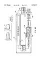
- FIG. 2shows elements of the traditional "Colton" capsule manufacturing machine.
- the elementsare a greaser section 21, a dipper section 22, spinners 23, upper drying kiln 24, lower drying kiln 26, table section 27 and automatics 28.
- FIG. 3A pinbar, having thirty pins 31 mounted to a bar 32, is shown in FIG. 3.
- FIG. 4shows gel 41 formed around a pin 31 to a dip line 42. Also shown is the trim line (cut-point) 43 and the area 44 on the pin above the dip line.
- FIG. 5shows a prior art stripper 51 about to push a capsule part 53 off a pin from the area 44 above the dip line with pushing face 52.
- FIG. 6shows a side view of a prior art stripper having a pivot 61 and a spring 62 in FIG. 6.
- FIG. 7shows a knife 71 trimming a capsule part to remove the rough edge 72 and create a clean edge 73.
- U.S. Pat. Nos. 1,978,829 (to Wilkie), 3,632,700 (to Oglevee), 3,794,453 (to Padilla et al.), 4,705,658 (to Lukas) and 4,997,359 (to Lebrun)are all directed to processes for manufacturing gelatin capsules.
- the Wilkie patentdiscloses an apparatus for drying capsules by directing a stream of air at the part of the capsule that contains the most moisture. A fine stream of air passing through a hole in a plate is directed to the closed end of the capsule so that a greater drying effect is experienced on the closed ends of the capsule than on the sides of the capsule.
- a plateis provided having multiple holes spaced to match the position of the pins.
- the Oglevee patentdiscloses a method for insuring capsule wall thickness uniformity by measuring the viscosity of the liquid gel solution in the dipping tank and causing corrective change in viscosity by changing the evaporative exposure or by adding lower viscosity gel to the tank.
- the Padilla patentdiscloses an air duct directing cooling air onto freshly dipped capsule mold pins for improved wall thickness characteristics.
- the ductis an air conduit for moving cool air upwardly against the rounded ends of the coated pins for uniform flow.
- the ductencloses a zone surrounding the array of pins.
- the Lukas patentis directed to reducing the drying time in the manufacture of hard shell gelatin capsules. Pins are irradiated with microwave energy until the gelatin dries.
- the Lebrun patentdiscloses a dipping bath, having a plurality of small wells and an impeller for maintaining the solution in the wells at a constant temperature. The pins dip into the wells.
- U.S. Pat. No. 4,758,149 to Sauteris directed to a capsule forming pin having a cylindrical sidewall and a groove extending around the cylindrical sidewall, the groove having a non-angular cross-sectional profile, both the cylindrical sidewall and the groove having a smooth burnished-hardened surface.
- Sauterdiscloses in FIG. 3A, item C and column 4, line 45, that a prior-art capsule cap pin for a "0" ("zero") size capsule has a diameter at the cut-point of 0.2973-0.2978 inch (7.551-7.564 mm).
- the prior-art capsule body pin at the cut-pointis 0.2848-0.2853 inch (7.234-7.247 mm).
- Table 4shows the nominal cut-point diameter for the prior art body pin and the prior art cap pin used in forming, respectively, the gelatin capsule body and the gelatin capsule cap.
- An improved methyl cellulose ether compositionthat may be used in the present invention is disclosed in U.S. Pat. No. 4,001,211 to Sarkar. Sarkar also discloses a process for the manufacture of capsules from his improved methyl cellulose ether composition.
- the improved methyl cellulose ether composition disclosed by Sarkaris an aqueous solution of a thermal gelling methyl cellulose ether composition suitable for use in preparing pharmaceutical capsules by an aqueous dip coating process using preheated pins and having a methoxyl DS of about 1.5-2.0, a C 2 -C 3 hydroxyalkyl MS of about 0.1-0.4, a 2 wt. percent aqueous solution viscosity of about 2-10 cps at 20° C.
- compositionhaving as a 15-30 wt. percent aqueous solution: (A) essentially Newtonian fluid properties as defined by a power law coefficient, n, of 0.9-1.0 at shear rates of between 0.1-10 sec -1 , and (B) a 50 sec gel yield strength of at least 150 dynes/cm 2 at 65° C.
- U.S. Pat. No. 4,993,137 to Mutois directed to the manufacture of capsules made from the improved methyl cellulose ether composition of Sarkar.
- Mutodiscloses a process for gelling the solution by dipping solution-coated pins into thermally controlled water. In the Muto process, the solution is gelled on the surface of the pins by first dipping the pins into solution and thereby coating the pins with solution and then dipping the coated pins into heated water to set the gel.
- U.S. Pat. Nos. 2,526,683 (to Murphy), 2,671,245 (to Kath), 3,617,588 (to Langman) and 3,842,242 (to Chisholm)are directed to methods of manufacture of capsules from methyl cellulose (the original methyl cellulose, not the improved methyl cellulose disclosed by Sarkar).
- the Murphy patentis the original patent for the manufacture of methyl cellulose capsules. This patent discloses the preheating of pins prior to dipping so that the solution adheres to pins in gelled form, the use of a sequence of different "successively warmer temperatures" through the drying kiln, drying using infrared lamps, and cooling by air. Murphy accomplished a mechanization for the manufacture of cellulose capsules.
- the Kath patentdiscloses apparatus for manufacturing either gelatin or methyl cellulose capsules. It discloses the use of tracks and a plurality of pins. The pins are moved along the tracks and moved, rotated and gyrated as needed through the various stations. This patent contains detailed mechanical disclosure.
- the Langman patentis directed to elimination of unwanted thermal gelation in the coating bath by the use of low viscosity hydroxyalkayl cellulose ethers and the rapid immobilization of the dip coating by induction heating after removal of the pins from the bath.
- the Chisholm patentis directed to heating the pins prior to dipping and discloses apparatus for preheating capsule pins in a "Colton" capsule machine.
- a trayis provided containing spheroidal particles heated to a predetermined temperature. The pins are dipped into the heated particles just prior to being dipped in the solution.
- a method and apparatus for manufacturing pharmaceutical capsuleseach capsule consisting of a capsule body and a capsule cap, uses an aqueous solution of a thermogelling cellulose ether composition and uses capsule body pins and capsule cap pins as molds.
- a group of pinsis mounted on a bar. The method involves heating the pins; dipping the pins into the solution to cause the solution to gelatinize on the surface of the pins; removing the pins from the solution; drying the gelatinized solution on the surface of the pins to form capsule bodies and capsule caps; and removing the capsule bodies and capsule caps from the pins.
- the time interval between heating and dippingmay vary from bar to bar. To compensate, each bar is heated to a different temperature according to the time interval associated with the bar.
- Pinsmay be heated by radiant energy or by hot air or via the bar at a plurality of thermally isolated stations. Additionally a portion of the bar may be heated to a predetermined temperature.
- the processincludes heating the pins before dipping and heating the pins after dipping.
- the dipping dishes for capsule bodies and capsule capsare spaced apart farther than in the traditional Colton machine and a pre-dip heating area is located between the dipping dishes.
- Drying the pinsincludes providing counterflow movement of air through an enclosure over the pins such that the pins initially encounter relatively humid air and, as they become drier, they encounter increasingly drier air.
- the pinsare heated so that the capsule bodies and capsule caps are dried from the inside-out. Removing the capsule parts from the pins involves gripping the capsule parts between opposing gripping surfaces.
- the capsule partshave a thicker wall than the equivalent size gelatin capsule and capsule bodies include a stiffening ring.
- thermally isolated heating elementsare provided below the bars and radiant heaters are provided above the bars to allow selective heating of bars or portions of bars to eliminate temperature differences at the time of dip.
- the dipping dishesare moved away from the centerline and thermal convection heaters and radiant heaters are inserted.
- thermal conduction heating via the back of the barsis also provided.
- inside-out dryingis provided.
- Post-dip heatingis used in addition to pre-dip heating.
- Post-dip heatingcontinues the gelling process after dip, assures rapid firming of the cellulose film, and supports inside-out drying.
- a fully enclosed drying kilnis provided to support inside-out drying, humidity control of air surrounding the pins, and energy efficiency.
- a gripperis provided.
- the pinis undersized to compensate for the unexpected differential in shrinkage between the cellulose capsule and the gelatin capsule.
- a pinis further undersized to allow a thicker capsule wall. Also the body pin adds an extra circumferential reinforcing ring to the capsule body between the lock ring and the dome.
- FIGS. 1A, 1B and 1Cshow a prior art capsule body and cap.
- FIG. 2shows the elements of the traditional (prior art) capsule manufacturing machine.
- FIG. 3shows pins mounted on a pinbar (prior art).
- FIG. 4shows a pin dipped to a dip line (prior art).
- FIG. 5shows a prior art stripper pushing a capsule part off a pin.
- FIG. 6.shows a prior art stripper
- FIG. 7shows a knife trimming the rough edge of the capsule (prior art).
- FIG. 8Ashows a schematic embodiment of the present invention, including a preheat section and a kiln enclosure.
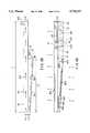
- FIG. 8Bis a schematic cross-sectional elevation view of the drying kiln showing the enclosure and air flow.
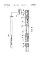
- FIG. 8Cshows location of the heating elements and fans in the enclosure of FIG. 8B.
- FIG. 8Dshows a schematic plan view of all sections between the split deck and the spinners.
- FIGS. 8E and 8Fshow two elevation views of the convection preheat system.
- FIG. 8Gshows the insulation box for the table section.
- FIG. 9shows a schematic embodiment of the present invention, including locations of the several preheat sections.
- FIGS. 10A and 10Bshow temperature sensors and underdeck heaters associated with the split deck.
- FIG. 10Cshows a group of cap pinbars and the corresponding group of body pinbars.
- FIG. 10Dshows the split deck layout for the bars of FIG. 10C.
- FIG. 11shows non-contact temperature sensors and overhead heaters associated with the split deck.
- FIGS. 12 and 13show a plan and elevation view respectively of a dipper section preheat arrangement.
- FIGS. 14A and 14Bshow two views of a preheater with air ducts for selectively heating pins.
- FIG. 15shows the gel dish temperature control scheme.
- FIGS. 16A, 16B and 16Cshow apparatus for heating the pins through the pinbar to permit post-dip gelling in the spinner section and "inside-out drying" in the drying kiln.
- FIG. 17illustrates the process of removing the capsule part from the pin.
- FIG. 18gives detail of the stripper of FIG. 6 as modified for the present invention.
- the present inventionprovides improvements over the method of manufacture of pharmaceutical capsules disclosed in U.S. Pat. No. 4,001,211 to Sarkar.
- the Sarkar cellulose compositionis particularly suited for preparing pharmaceutical capsule shells which dissolve at a rate comparable to gelatin capsules.
- Delay release characteristicscan be obtained by incorporation of a less water-soluble cellulose such as ethyl cellulose as described by Greminger and Windover in U.S. Pat. No. 2,887,440.
- the present inventionuses the improved thermogelling methyl cellulose ether compositions disclosed in the Sarkar patent, including a thermal gelling methyl cellulose ether composition suitable for use in preparing pharmaceutical capsules by an aqueous dip coating process using preheated pins and having a methoxyl DS of about 1.5-2.0, a C 2 -C 3 hydroxyalkyl MS of about 0.1-0.4, a 2 wt. percent aqueous solution viscosity of about 2-10 cps at 20° C. and a thermal gel point of about 50°-80° C., and a 15-30 wt.
- a thermal gelling methyl cellulose ether compositionsuitable for use in preparing pharmaceutical capsules by an aqueous dip coating process using preheated pins and having a methoxyl DS of about 1.5-2.0, a C 2 -C 3 hydroxyalkyl MS of about 0.1-0.4, a 2 wt. percent aqueous solution viscosity of about 2-10 cps at
- percent aqueous solution viscosityof about 1,000-10,000 cps at 20° C., said composition being further characterized by having as a 15-30 wt. percent aqueous solution: (A) essentially Newtonian fluid properties as defined by a power law coefficient, n, of 0.9-1.0 at shear rates of between 0.1-10 sec -1 , and (B) a 50 sec gel yield strength of at least 150 dynes/cm 2 at 65° C.
- Aessentially Newtonian fluid properties as defined by a power law coefficient, n, of 0.9-1.0 at shear rates of between 0.1-10 sec -1
- Ba 50 sec gel yield strength of at least 150 dynes/cm 2 at 65° C.
- the apparatus of the present inventionin a preferred embodiment, is based on the type of capsule machine disclosed in U.S. Pat. No. 1,787,777 to Colton and U.S. Pat. No. 2,671,245 to Kath.
- the machine that was modified to embody the present inventionwas a "Colton" capsule machine manufactured by R & J Engineering Corporation, 100 Hansen Avenue, Kitchener, Ontario, Canada N2C 2 E2.
- the present inventionprovides a production process and a fully mechanized production apparatus that may use the modified cellulose in U.S. Pat. No. 4,001,211 to Sarkar for manufacturing pharmaceutical capsules of sufficient uniformity and rigidity that they may be filled on modern high-speed capsule filling machines.
- Capsulesmay be made in a range of sizes similar to the range of sizes in Tables 1-3.
- the capsule bodies and capsule capshave different dimensions as illustrated for the prior art capsules in FIGS. 1A-1C.
- the processinvolves a series of steps performed by one machine. Each capsule part is made by dipping a hot stainless steel pin into a cellulose gel solution and drying the gel to form a hard film over the pin. The pins are mounted in a row on a bar as illustrated in FIG. 3.
- FIG. 4shows a pin with a gel coating.
- Body pinsare mounted on one set of bars and cap pins are mounted on a corresponding set of bars so that corresponding bodies and caps may pass through the entire process in phase with each other and emerge from the process facing each other positioned for assembly as a capsule.
- the processin a first embodiment, is arranged so that the bars travel in a continuous loop illustrated in FIG. 8A.
- the process steps in this embodimentare:
- FIGS. 17 and 7Removing and trimming the caps and bodies is illustrated in FIGS. 17 and 7 respectively. Joining the caps and bodies to form a capsule in a prelock position, ready for filling, is illustrated in FIGS. 1A and 1B. FIG. 1C shows a capsule with the lock ring engaged as it would be after filling.
- the processis similar to the process for manufacturing gelatin capsules except that the process for manufacturing gelatin capsules involves dipping cold pins into a gel whose temperature is above the gel point whereas the process for manufacturing cellulose capsules involves dipping hot pins into a gel whose temperature is below the gel point.
- Novel aspects of the present inventioninclude process steps designed to overcome the peculiar difficulties of manufacturing cellulose capsules using the cellulose composition disclosed in the Sarkar patent.
- the present inventionuses temperature, humidity and air flow control components including heaters, sensors, enclosures, fans and thermal isolation components.
- This embodimentalso uses pins that are narrower than the pins used in the prior art and in one embodiment provides a capsule body having a stiffening ring.
- Capsulesmust have consistent wall thicknesses from capsule to capsule for them to be filled on high-speed filling machines. To accomplish this, the temperature of the stainless steel pin molds, which are attached to a pinbar, must be controlled throughout the process. The pins must be heated uniformly so that a repeatable amount of gel is picked up on each pin in the dipping operation. While several patents speak about the need to heat the pinbars prior to dip, none address the critical need for heating all pins from bar to bar to substantially the same temperature to produce capsules sufficiently uniform for high-speed filling. In the process of making cellulose capsules on a traditional "Colton" capsule machine, some pinbars must wait longer than others to dip.
- the present inventionincludes compensatory temperature control where some bars or parts of bars are independently heated to higher temperatures than others to compensate for the longer wait these bars have before dipping and for the different ambient temperature (due to temperature gradients within the machine) experienced during the wait, and also for temperature gradients resulting from differing pin, pinbar, and/or deck conductivities.
- the compensatory temperature control systemoperates to maintain predetermined temperatures in the bars prior to dipping to achieve substantially equal temperatures in the pins at the time of dipping.
- Compensatory temperature controlcan be provided by a variety of equipment configurations as follows:
- Groups of twenty barsmove from drying station to drying station on a metal deck. Since bars sit in each position for some time before moving, heating sources may be positioned under the deck and also over the bars in such a manner so that heat may be applied to raise the temperature of selected bars in the group of twenty.
- the last station of the lower deck, just prior to the table section,provides separate heating areas that are thermally isolated from each other so as to heat bars and portions of bars selectively.
- bars leave the drying decks and load onto the table sectionthey are fed one at a time into the center elevator for processing one at a time in the automatics section.
- the last bar in the group of twentymust wait the longest. By selectively heating these later bars to higher temperatures, the delay before dip is compensated for. At time of dip, these later bars will have a temperature substantially equal to the earlier bars that had less time to cool down before entering the dipping station.
- barsare fed from the deck onto a Table Section which takes the group of twenty bars and feeds them one at a time into the T-slides for continued processing.
- heatcan be applied by any means to maintain the later bars at the required temperature so that they do not cool as they wait their turn for further processing.
- the table sectionis covered with an insulated box with heat sources to maintain temperatures and further accommodate the later bars so that all bars reach the dipping bath at substantially the same temperature.
- the differential heating mentioned abovealso may be set up to compensate for temperature gradients within the machine in order to ensure uniformity of temperature, pin to pin, along a given bar. This is accomplished by applying heat selectively via the deck supporting the bars and from overhead radiant heaters.
- Drying techniques used in prior art mechanized capsule manufactureinvolves overhead kilns with perforations on the bottom plate through which air blows over the capsules. The air then escapes into the room.
- the present inventionuses enclosed kilns where air is only introduced at the pin-exit end of the lower kiln (i.e., the end of the drying process) and then proceeds in a counterflow direction to the pinbar movement, all air being contained in the enclosed kilns and being removed at the pin-entry end of the top kiln, which is the beginning point of the drying process.
- the pins, on entering the drying processencounter relatively humid air and, as the pins move through the drying process and become drier, they encounter increasingly drier air.
- All capsule dryingwas formerly accomplished by drying from the outside by blowing air over the pins from above.
- the present inventiondries from the inside-out by using heat both from beneath the deck and also from above the pins (radiant or infrared, microwave, etc.) to heat the pins themselves, thus driving the moisture out from the inside. This gives more uniform capsules free from defects of wrinkles and corrugations common with outside-in drying, and avoids the case hardening or skinning over that occurs in cellulose capsule production by drying with air alone.
- the present inventionprovides a preheat area whose specific purpose is to apply heat to the pins without contact in preparation for dipping. This preheat area can be in any or all of the following places:
- the present inventionalso includes extending the dipper section on both cap and body sides to move the dipping dishes further out from the centerline of the longitudinal axis of the traditional capsule machine. This allows space to accommodate a preheat process that does not involve contact with the pins.
- FIG. 8Ashows some elements of a first schematic embodiment the apparatus of the present invention, most notably a preheat section 80, a kiln enclosure 81, with air ingress aperture 82 and air egress aperture 83, an insulated, heated table section enclosure 84, an insulated, heated spinner section enclosure 85 and a dipper section having a built-in preheat portion 86.
- the arrows in FIG. 8Aindicate the direction of pin movement through the machine.
- FIG. 9shows a schematic embodiment of the apparatus of the present invention including several preheat sections, as follows: in the drying kiln 80, between the drying kiln and the table section 91, on the table section 92, between table and automatics 93, between automatics and greaser 94, between greaser and dipper 95, and in the dipper section 96.
- FIG. 8Bshows the overall physical shape of kiln.
- the overall length L1 of the machinei.e., the length of the upper kiln, is 44 feet (13.4 m). This is longer than the traditional Colton machine, the upper kiln having been extended by three table-lengths to accommodate a new preheat section 94 (shown in FIG. 8C) between the automatics and the greaser.
- the height H1 of the upper kilnis 2 feet (61 cm).
- the length L2 of the lower kilnis 26 feet (7.9 m).
- the height H2 of the lower kiln at the split deckis 2 feet (61 cm) and the height H3 of the lower kiln at the back elevator is 1 foot (30 cm).
- the walls of the kilnare insulated.
- the kilncomprises an enclosure 81 having air entrance duct 801 and air exit duct 802.
- the direction of air flowis indicated by arrows 803.
- FIG. 8Clocates the two 6-inch (152-mm) circular duct fans 805 and the single 10-inch (254 mm) duct fan 807, all mounted in the lower kiln 26, which power the air flow though both kilns.
- the two duct fans 805are mounted side by side so as to blow air in a direction substantially parallel to the axis of the lower kiln toward the back of the machine, drawing air from inlet 801 and driving it into the upper kiln 24.
- agitator fans 804 in the upper kilnare arranged in four pairs of side by side fans, each pair directed to blow air downwardly onto the pins so as to speed local drying of the gel with agitated (i.e., temperature-equalized) air.
- Heat for inside-out drying and preheatis supplied by a series of five 22 inch by 17 inch (56 cm by 43 cm) radiant panels 808 mounted directly above the moving pinbars in the lower kiln.
- General preheat of the pinbars in the split deck positionis provided from above by a 22 inch by 17 inch (56 cm by 43 cm) group of radiant panels 809 directly above the pinbars and preheat is applied selectively to portions of pinbars by conduction from the split deck assembly 810 that supports the pinbars.
- a "dome-setter" radiant panel 811is provided for post-dip heating to facilitate post-dip gelling and inside-out drying.
- the fan and heater configuration described aboveapplies to one side, cap or body, and, in this respect, the cap and body sides are substantially identical, except that they are the mirror image of each other.
- Inlet air temperature to the kilnis controlled in the range 125°-180° F. and is preferably 160° F. Absolute humidity of the air at the inlet is controlled in the range 0.006-0.012 lb moisture/lb air (0.6-1.2 percent) and is preferably 0.009 lb moisture/lb air (0.9 percent).
- Air flow rate through the body side of the kilnis 63 feet/min (0.32 m/sec) measured at the 8 inch (203 mm) body side inlet duct.
- the corresponding flow rate through the cap side kiln measured at a cap side inlet duct of the same sizeis 7 feet/min (0.036 m/sec).
- the flowing airis cooled by evaporative cooling and is heated by heat from the bars and from the radiant panels.
- the temperature profile found to provide acceptable capsule partsis given in Table 5.
- Heat from the radiant panels and thermal conduction heatersis adjusted to maintain the predetermined temperatures of Table 5.
- Pressure drop across the kilnis 0.020 inches of water (0.005 kPa) (body side) and 0.005 inches of water (0.012 kPa) (cap side). This indicates how much greater the air flow rate through the body side is than the air flow rate through the cap side.
- FIGS. 10A and 10Bshow temperature sensors and under-deck heaters for preheat on the split deck in the drying kiln.
- FIGS. 10A and 11give details of split deck 810 and radiant panel 809 respectively from FIG. 8C.
- FIG. 10Ashows sensors 104 mounted in deck 101. Heaters 103 are mounted under the deck. Both sensors and heaters are electrically connected to controllers 105 which maintain the predetermined temperatures given in Tables 6A and 6B.
- the deckitself contains thermal isolators 102, so that the several sections of deck beneath a given pinbar are thermally isolated one from another. Cap pinbars move in groups of twenty from station to station approximately every 40-70 seconds in the drying kilns and body pinbars do likewise.
- FIG. 10CThe direction of movement of the pinbars is shown by the arrows in FIG. 10C.
- Such a group of pinbarshas a length of 22 inches (56 cm), the length of one pinbar, and a width of 17 inches (43 cm), the width of twenty pinbars.
- Supporting the pinbars in the last station of the drying kilnis the split deck shown in plan view in FIG. 10D.
- the thermal isolators 102 and the portions of the deck 101 enclosed by the thermal isolatorsare also shown in cross-section elevation view in FIG. 10A.
- Selective heating of different portions of twenty pinbars to compensate for pre-dip dwell time and for temperature gradient in the machineis achieved by controllers 105 controlling each of the several enclosed deck portions at a predetermined temperature.
- a temperature profile for a preferred embodiment of the present inventionis given for each enclosed deck portion 101 of FIG. 10D in Table 6A for the cap side and Table 6B for the body side.
- FIG. 11shows non-contact temperature sensors and overhead radiant heaters for general preheat on the split-deck in the drying kiln, detail 809 of FIG. 8C.
- Non-contact sensors 111measure the temperature of the pins (or local area of pinbar) from above.
- Overhead radiant heaters 112are mounted to the thermal enclosure 113. Controllers 106 are used (in conjunction with controllers 105) to maintain the predetermined temperatures of Tables 6A and 6B on the split deck.
- hot airmay be used for heating in the split deck area.
- FIG. 8Gshows the insulation box 831 for preserving preheat in the table section 27.
- the boxhas a top and only two sides, one side being omitted to allow a group of twenty bars to enter and another side being omitted to allow bars to exit (in a direction transverse to their length) one at a time.
- FIG. 8Clocates (schematically) the table section 27, the automatics 28, the convection preheat section 94, the greaser section 21, the dipper section 22 and the spinners 23.
- the convection preheat section 94includes up to three convection heat systems 812 on each side. Arrows 813 indicate the direction of flow of heated air across the pinbar after the pinbar has left the automatics where capsules were removed and before the pinbar enters the greaser section 21 and the dipper 22.
- the location of each of the six convection preheat systems 812is shown in FIG. 8D between automatics 28 and greaser section 21.
- the convection preheat systemis shown in greater detail in FIGS. 8E and 8F.
- FIG. 8E and 8FThe convection preheat system is shown in greater detail in FIGS. 8E and 8F.
- FIG. 8Eshows the squirrel cage blower 821, the heating element 822, the supply duct 823, the pinbar 824, the pin 825 and the return duct 826.
- the original Colton machinewas extended by three table-lengths, i.e., the upper kiln was extended by three table-lengths and the greaser section was moved three table-lengths away from the automatics.
- four convection preheat systemsare used, two on each side.
- FIG. 8Dalso shows a schematic plan view of all sections between the split deck 810 and the spinners 23, including the accumulators 832 and the final preheat section 95, whose location necessitates that the dishes are located farther apart than they are in the traditional Colton machine.
- Lubrication used in the greaser section 21consists of admixture of light mineral oil (59 percent), stearic acid (16 percent), calcium stearate (16 percent), and lecithin (9 percent). A very small measured quantity is delivered by a metering pump to a felt or brush which applies the lubricant directly to the pins. Then a felt-lined barrel distributes the lubricant uniformly over the pin surface.
- FIGS. 12 and 13show a plan and elevation view respectively of a dipper section preheat arrangement.
- Body pinbars and cap pinbarsslide into the dipper section preheat area in T-slides 121 and drop onto guide rails 124.
- the dipper dishesare spaced apart to allow an area for the final preheat section 95. See also FIG. 9. Heated air is blown across the pinbars via inlet ducts 123 and preheat hoods 122.
- the pinbars, leaving the preheat areaare dipped in groups of five in the dipping dish 125 and spun in the spinners 23 within an enclosure 161.
- FIG. 13shows a group of five bars in the accumulator 832 (five bars having fallen from the T-slides one at a time until five bars are accumulated in the accumulator). This group of five bars moves to station 131 in the final preheat section 95 where final preheat is applied.
- the dishesare moved apart further to accommodate a sufficient number of stations 131.
- all preheatis performed between the accumulator and the dishes and is performed without disturbing the layer of grease that was applied to the pins on the greaser.
- Heatis preferably applied by thermal convection from hot air flowing over the pins as shown in FIG. 13, or by radiant heat. Heat may also be applied by moving a conducting bar into contact with the top surface of the bars, the pins pointing down as shown in FIG. 13. Alternatively, induction heating may be used.
- FIGS. 14A and 14Bshow two views of a preheater with air ducts for selectively heating pins in the T-Slides. Air for heating the pins passes through supply ducts 141 and return ducts 142. The local temperature of the pinbar is measured by non-contact sensor 143. This is an alternative to the convection preheat section of FIGS. 8E and 8F.
- FIG. 15shows the schematic for control of the dish temperatures.
- Water 157is pumped by circulating pump 151 through a chiller 152 and a heater 153.
- the heateris controlled by a PID controller 154 connected to a temperature sensor in the body dish 155. After the water leaves the heater, it flows through jackets around both the body dish 155 and the cap dish 156. The temperature in both dishes is controlled to 81° F. ⁇ 1° F. (27.2° C. ⁇ 0.6° C.).
- Body pinsshould enter the dish at a temperature of 152° F. (66.7° C.) (range 144° F.-156° F. (62.2° C.-68.9° C.)) and cap pins at a temperature of 151° F. (66.1° C.) (range 149° F.-156° F. (65.0° C.-68.9° C.)). After a pin has been dipped, its temperature should be in the range shown in Table 8.
- FIGS. 16A, 16B and 16Cshow apparatus for heating the pins through the pinbar to permit post-dip gelation in the spinner section and "inside-out drying" in the drying kiln.
- the spinner sectionis enclosed and heat is applied to the pins to cause continued gelation and inside-out drying.
- Heatis applied in the spinner section by blowing hot air over the pins via ducts 163 and 164 and by heating the pins from radiant panels 162 mounted to the walls of the enclosure 161.
- Panels 162are substantially parallel to the longitudinal axes of the bars. It has been found that using a pin temperature at dipping that is cooler than the temperature used by Murphy, and heating the pins after dipping to continue gelation, provides a better consistency and fewer defects in the finished capsule.
- Heat applied to the pinbar in the drying sectiondrives moisture from the inside-out as shown in FIGS. 16B and 16C (inside-out drying). Arrows in FIG. 16C in the bar and pin indicate flow of heat. Arrows in FIG. 16C in the gel and in the air indicate flow of moisture. Inside-out drying prevents the formation of "skin" on the outer surface of the capsule that can occur when drying from the outside with blown air alone.
- FIG. 17illustrates the process of removing the capsule part from the pin.
- a gripper 171modified stripper pivots about pivot 172, when driven by wedge 173, to grip the capsule part 174 prior to sliding it off the pin.
- the gripperhas opposed gripping faces.
- FIG. 18gives details of the gripper of FIG. 6.
- the gripping faces 181may be provided with raised ridges or rows of teeth (which may be longitudinal or circumferential to the axis of the pin), or have surface composition or texture, so as to grip the capsule.
- An important factor in achieving production quantities of capsule bodies and caps that will run problem-free in high-speed filling machinesis to meet close specifications, especially on external dimensions. For example, if the external diameter of each capsule part is even slightly too large, caps and bodies will not consistently separate in the filling chamber because they are too tight a fit.
- the external diameter of a capsule partis determined by the diameter of the pin mold, the shrinkage of the capsule material after removal from the mold, and the thickness of the capsule wall.
- the thickness of the capsule walldepends on a number of factors including the initial moisture content and viscosity of the gel and the drying conditions. Accordingly, it is recommended, for the manufacture of a cellulose capsule part, to use a pin whose diameter is undersized compared to the capsule pin for the corresponding size gelatin capsule part.
- the pin diametermay be undersized proportionately. From Table 4, the cut-point diameter of the prior art capsule cap pin is 0.2975 inch (7.56 mm) so a reduction range of 0.002-0.006 inch (0.05-0.15 mm) represents a reduction range of 0.7%-2.0% and a reduction of 0.004 inch (0.1 mm) represents a reduction of 0.13%.
- the pin diametermay be reduced further as discussed under "Increasing Capsule Stiffness" hereinbelow.
- Cellulose capsules made from the improved methyl cellulose ether composition disclosed by Sarkarare found to be less rigid than gelatin or earlier cellulose capsules of an equivalent shape, size and wall thickness. Also, it is essential that the capsule parts retain their shape in order to pass freely through the high-speed filling machine. For these reasons it has been found beneficial to increase the wall thickness of the capsule parts without increasing the external diameter of the capsule. (The external diameter of the capsule is the external diameter of the capsule cap.) Increasing the wall thickness for a given capsule size is accomplished by using a thinner cap pin, a thinner body pin and a combination of hotter pin and/or thicker solution.
- To increase the wall thickness of a capsule cap by an additional dimension ⁇ w without increasing the external diameterit is necessary to reduce the diameter of the cap pin by approximately 2 ⁇ w.
- To make the corresponding capsule bodyit is necessary to reduce the diameter of the body pin by approximately 4 ⁇ w so that the body will fit into the smaller inside diameter of the cap.
- the cap pin diameteris reduced by 0.001 inch (0.026 mm) and the body pin diameter is reduced by 0.002 inch (0.052 mm) in addition to the reduction discussed hereinbelow under "Capsule External Diameter and Pin Mold Diameter.”
- the cut-point diameter of the prior art cap pinis 0.2975 inch (7.56 mm), so an additional reduction 0.001 inch (0.026 mm) represents an additional reduction of 0.3%.
- the cut-point diameter of the prior art body pinis 0.2855 inch (7.25 mm), so an additional reduction of 0.002 inch (0.052 mm) represents an additional reduction of 0.7%.
- the stiffness of the capsulemay be increased by providing in the capsule body a reinforcing ring, similar to the locking ring, located between the locking ring and the dome of the capsule body.
- a reinforcing ringsimilar to the locking ring, located between the locking ring and the dome of the capsule body. This approach provides, for a given capsule wall thickness, a stiffer capsule with a reduced penalty in terms of material content of the capsule body and reduction in interior volume of the finished capsule.
- One or more reinforcing ringsmay be provided.
- An alternative embodiment of the present inventionuses serial dipping of pins instead of the batch dipping using a modified Colton machine as described hereinabove.
- Serial dippingpermits every pin to proceed through an identical preheat process. This eliminates the need to compensate for different elapsed time pin-to-pin between preheat and dipping. Dipping one pin at a time would, of course reduce the throughput rate by a factor of 150 over the embodiment of FIG. 8A in which there are thirty pins per bar and five bars are dipped together as a batch.
- the most acceptable areas for preheatingare those prior to the table section where the bars are assembled in groups of twenty and are stationary for a period during which they can all be heated together.
- the problem with preheating prior to the table sectionis that the action of the table section causes some bars to wait longer than others for their turn to dip and this can result in some bars cooling more than others prior to dipping, with the cooler bars making thinner capsule walls than the other bars.
- the pins on one end of the barmight be hotter or cooler than the pins on the other end of the bar simply due to temperature gradients across the machine.
- the size of the pin mold used in the prior artis a well accepted standard with little variation in size.
- the combination of the standard pin mold diameter, accepted standards of wall thickness, and shrinkagecontribute to an overall dimensional standard for the outside diameter of a capsule of a given size which can be accommodated without difficulty on high-speed filling machines where tolerances are tight.
- the prior artteaches that the same pin mold may be used for cellulose as is used for gelatin, and there is no prior art that has stated otherwise.
- using the prior art pin for a given capsule sizemakes a cellulose capsule that is often oversized compared the given standard size capsule. This causes difficulties in the high-speed filling machines.
- the traditional drying kilns in the prior artemploy plates with holes above the pins to introduce a stream of air in proximity to the capsules (Wilkie). Blowing air over the pins causes evaporative cooling which works well with gelatin since the cooling helps set the gel. However, with cellulose the object is to keep the gel above its thermal gel point until it is thermally set to a sufficient firmness.
- the traditional (Wilkie) designcools the wet cellulose gel through evaporative cooling, and can cause the gel to flow unevenly and uncontrolled down the mold pin. This makes an uneven capsule which cannot be filled on the precise high-speed filling machines.
- the improved celluloselacks the rigidity necessary for a clean release from the pin when contacted by the stripper cheek. There is a tendency for the cellulose part to continue to adhere to the pin and to deform and break under stripper pressure rather than releasing freely.
- cellulose capsulesA further complication in stripping cellulose capsules is the low moisture content. Whereas moisture can aid capsule removal in the gelatin process, cellulose capsules become soft at even modest moisture levels. Thus stripping must always be accomplished under dry capsule conditions. As with gelatin, dry capsules make capsule removal more difficult.
- the present inventionaddresses the issue of differential cooling and temperature compensation by selectively heating some bars to a higher temperature than other bars so that all bars have substantially the same temperature when dipped as a group of five or more. This is accomplished by using a pattern of thermally isolated heating elements below the bars (the "split deck") and above the bars (radiant heaters). These heating elements selectively heat certain bars to predetermined temperatures so that substantially equal temperatures are achieved at dip.
- the temperature of a barmay vary along its length or front to back.
- the split deckallows the selective heating of portions of bars, those portions which are otherwise repeatedly cooler than other portions.
- Thermal sensorsare used to maintain the individual heating areas at an appropriate temperature to consistently deliver all bars and portions of bars at substantially the same dip temperature.
- Preheating in the dipper sectionmay be accomplished by heating the pins by a non-contact heating method which overcomes the problems associated with Chisholm's heated particle method.
- Hot air, radiant elements, etc.may be used in proximity to the pins without disturbing the lubricant layer, and without the concern of deposits of lubricant on the contact particles.
- the present inventionmodifies the Colton style machine by extending it away from centerline on both the cap side and the body side.
- contact to the back of the bars(away from the pins) may be used to aid preheating in the dipper. Heated elements may be moved directly in contact with the back of the bars as sole preheating, or in conjunction with a non-contact heating method applied to the pin side of the bar.
- the apparatus of the present inventionincludes a pin mold which is undersized to compensate for the differential in shrinkage between capsules made from the improved cellulose composition and capsules made from gelatin. This results in a cellulose capsule which has the same overall diameter and wall thickness as the equivalent gelatin capsule, and is therefore capable of running in existing high-speed filling machines.
- the present inventiondoes not use plates with air blowing directly over the pins, but uses a fully enclosed drying tunnel (kiln), in which drying is accomplished by inside-out drying in the most critical stages of drying. This is accomplished by using heating elements directly under the deck (or bottom) of the drying tunnel and radiant elements overhead in the drying tunnel, keeping pins above the thermal gel point of the cellulose in the early drying stages. This drives moisture out from the inside. It avoids the skinning over and wrinkling associated with the outside-in drying of the prior art.
- Process airis directed through the enclosed drying tunnel in counterflow to the direction of motion of the pins.
- the purpose of the counterflow airis not so much to dry the capsule walls, but rather to move moisture through the system which has been driven out of the capsule parts by inside-out drying so the moisture can be exhausted from the drying kilns.
- drier capsules at the end of the drying tunnelcome into contact with dry air which is introduced at the end of the drying tunnel.
- wet capsules at beginning of the drying tunnelcome into contact with wet air and drier capsules at the end of the drying process come in contact with drier air.
- the "stripper" deviceis modified into a gripper, which has two opposed surfaces which grab the capsule above the dipped edge, on the capsule wall itself, and remove the capsule using pressure to the side walls in conjunction with a motion along the longitudinal axis of the pin mold.
- the Colton machineis modified to allow the grippers to open wider than normal strippers and the machine is also modified to move the gripper into a position closer to the closed end of the capsule so that it contacts on the capsule surface, rather than behind it. This action removes the capsule without damage to the open end, which often occurs when the prior art technique is used on cellulose capsule parts.
- the flexibility of capsules made from the improved cellulosecan cause capsules to malfunction in filling machines, particularly if deformed out of round.
- the apparatus of the present inventionprovides a pin which is undersized (in the correct amount) to allow a thicker capsule wall, and therefore better rigidity, while maintaining the accepted overall diameter of a given standard capsule size, such as "0", "1", etc.
- the apparatus of the present inventionalso provides a body pin which adds an extra circumferential ring to the capsule body between the lock ring and the dome which physically reinforces the capsule wall.
- One or more extra ringsmay be added to increase the overall strength of the capsule body part, and to assure capsule bodies remain circular.
Landscapes
- Health & Medical Sciences (AREA)
- Engineering & Computer Science (AREA)
- Mechanical Engineering (AREA)
- Physics & Mathematics (AREA)
- Oral & Maxillofacial Surgery (AREA)
- Thermal Sciences (AREA)
- Chemical & Material Sciences (AREA)
- Manufacturing & Machinery (AREA)
- Toxicology (AREA)
- Medicinal Chemistry (AREA)
- Pharmacology & Pharmacy (AREA)
- Life Sciences & Earth Sciences (AREA)
- Animal Behavior & Ethology (AREA)
- General Health & Medical Sciences (AREA)
- Public Health (AREA)
- Veterinary Medicine (AREA)
- Medical Preparation Storing Or Oral Administration Devices (AREA)
- Medicinal Preparation (AREA)
Abstract
Description
TABLE 1 ______________________________________ CAPSUGEL CAPSULE PART, EXTERNAL DIAMETER PRE-FIT ™ SNAP-FIT ™ or CONI-SNAP ™ Body Cap Sizes Inches mm Inches mm ______________________________________ 000 0.378 9.60 0.394 10.00 00 0.324 8.23 0.339 8.60 0 el 0.291 7.38 0.300 7.70 0 0.291 7.38 0.303 7.70 1 0.263 6.68 0.275 6.98 2 0.241 6.13 0.252 6.41 3 0.221 5.61 0.231 5.88 4 el 0.201 5.11 0.212 5.38 4 0.201 5.11 0.212 5.38 5 0.185 4.70 0.193 4.89 ______________________________________ Tolerance: ±0.001 (±0.03 mm)
TABLE 2 __________________________________________________________________________PRE-FIT ™ SNAP-FIT ™ or CONI-SNAP ™ Body Cap Body Cap Size Inches mm Inches mm Inches mm Inches mm __________________________________________________________________________000 0.0042 0.107 0.0044 0.112 -- -- -- -- ±0.0009 ±0.023 ±0.0012 ±0.030 00 0.0041 0.104 0.0042 0.109 0.0042 0.107 0.0043 0.109 ±0.0009 ±0.023 ±0.0012 ±0.030 ±0.0009 ±0.023 ±0.0012 ±0.030 0 el -- -- -- -- 0.0041 0.104 0.0042 0.107 ±0.0008 ±0.020 ±0.0010 ±0.025 0 0.0040 0.102 0.0042 0.107 0.0041 0.104 0.0042 0.107 ±0.0008 ±0.020 ±0.0010 ±0.025 ±0.0008 ±0.020 ±0.0010 ±0.025 1 0.0039 0.099 0.0041 0.104 0.0040 0.102 0.0041 0.104 ±0.0008 ±0.020 ±0.0010 ±0.025 ±0.0008 ±0.020 ±0.0010 ±0.025 2 0.0038 0.096 0.0040 0.102 0.0039 0.099 0.0040 0.102 ±0.0008 ±0.020 ±0.0010 ±0.025 ±0.0008 ±0.020 ±0.0010 ±0.025 3* 0.0034 0.086 0.0036 0.092 0.0035 0.089 0.0036 0.092 ±0.0008 ±0.020 ±0.0010 ±0.025 ±0.0008 ±0.020 ±0.0010 ±0.025 4 el -- -- -- -- 0.0037 0.094 0.0038 0.096 ±0.0008 ±0.020 ±0.0010 ±0.025 4 0.0034 0.086 0.0036 0.089 0.0034 0.086 0.0035 0.091 ±0.0008 ±0.020 ±0.0010 ±0.025 ±0.0008 ±0.020 ±0.0010 ±0.025 5 0.0034 0.086 0.0036 0.092 -- -- -- -- ±0.0008 ±0.020 ±0.0010 ±0.025 __________________________________________________________________________ 3* SNAPFIT ™ Body Target -- 0.0034 ± 0.0008
TABLE 3 ______________________________________ SCHERER LOX-IT ™ CAPSULE PART DIAMETER Size 0 1 2 3 4 ______________________________________ CAP 0.301" 0.272" 0.250" 0.230" 0.210" DIAMETER* (±0.003) BODY 0.289" 0.262" 0.240" 0.220" 0.200" DIAMETER* (±0.003) ______________________________________ *DETERMINED AT CUT EDGE
TABLE 4 ______________________________________ PIN CUT-POINT DIAMETER Body Cap Sizes Inches mm Inches min ______________________________________ 00 0.3195 8.12 0.3355 8.52 0 0.2855 7.25 0.2975 7.56 1 0.2575 6.54 0.2685 6.82 2 0.2355 5.98 0.2455 6.24 3 0.2155 5.47 0.2255 5.73 4 0.1955 4.97 0.2045 5.19 ______________________________________
TABLE 5 ______________________________________ ACCEPTABLE AIR TEMPERATURE PROFILE Body Kiln Cap Kiln Location Air Temperature Air Temperature in Kiln °F. °C. °F. °C. ______________________________________ A 111 43.9 111 43.9 B 109 42.8 108 42.2 C 110 43.3 107 41.7 D 110 43.3 106 41.1E 111 43.9 104 40.0 F 114 45.6 104 40.0 G 120 48.9 105 40.6H 123 50.6 112 44.4 I 142 61.1 140 60.0J 151 66.1 159 70.6 K 149 65.0 147 63.9 ______________________________________
TABLE 6A ______________________________________ CAP SIDE SPLIT DECK TEMPERATURE PROFILE A B C D °F. (°C.) °F. (°C.) °F. (°C.) °F. (°C.) ______________________________________ 1 306 (152) 251 (122) 235 (113) 267 (131) 2 181 (82.8) 178 (81.1) 153 (67.2) 174 (78.9) 3 193 (89.4) 165 (73.9) 135 (57.2) 142 (61.1) ______________________________________
TABLE 6B ______________________________________ BODY SIDE SPLIT DECK TEMPERATURE PROFILE A B C D °F. (°C.) °F. (°C.) °F. (°C.) °F. (°C.) ______________________________________ 1 246 (119) 191 (88.3) 252 (122) 288 (142) 2 213 (101) 125 (51.7) 193 (89.4) 154 (51.1) 3 209 (98.3) 195 (90.6) 273 (134) 261 (127) ______________________________________
TABLE 7 __________________________________________________________________________CAP AND BODY SIDE, DECK SECTION DIMENSIONS A B C D Inch (mm) Inch (mm) Inch (mm) inch (mm) __________________________________________________________________________1 3 × 4 (76 × 102) 5 × 4 (127 × 102) 5 × 4 (127 × 102) 3 × 4 (76 × 102) 2 3 × 10 (76 × 254) 5 × 10 (127 × 254) 5 × 10 (127 × 254) 3 × 10 (76 × 254) 3 3 × 4 (76 × 102) 5 × 4 (127 × 102) 5 × 4 (127 × 102) 3 × 4 (76 × 102) __________________________________________________________________________
TABLE 8 ______________________________________ PIN TEMPERATURE AFTER DIPPING Optimum Minimum Maximum Temperature °F. (°C.) °F. (°C.) °F. (°C.) ______________________________________ Location Table Load Body 124 (51.1) 123 (50.6) 126 (52.2) (Spinner) Cap 122 (50.0) 121 (49.4) 124 (51.1) Table 1 of Body -- 119 (48.3) 121 (49.4) Upper Deck Cap -- 120 (48.9) 124 (51.1) ______________________________________
Claims (41)
Priority Applications (1)
| Application Number | Priority Date | Filing Date | Title |
|---|---|---|---|
| US08/716,932US5750157A (en) | 1991-05-31 | 1996-10-10 | Apparatus for the manufacture of pharmaceutical cellulose capsules |
Applications Claiming Priority (5)
| Application Number | Priority Date | Filing Date | Title |
|---|---|---|---|
| US70802391A | 1991-05-31 | 1991-05-31 | |
| US89309192A | 1992-05-29 | 1992-05-29 | |
| US08/377,669US5698155A (en) | 1991-05-31 | 1995-01-24 | Method for the manufacture of pharmaceutical cellulose capsules |
| US46305395A | 1995-06-05 | 1995-06-05 | |
| US08/716,932US5750157A (en) | 1991-05-31 | 1996-10-10 | Apparatus for the manufacture of pharmaceutical cellulose capsules |
Related Parent Applications (1)
| Application Number | Title | Priority Date | Filing Date |
|---|---|---|---|
| US46305395AContinuation | 1991-05-31 | 1995-06-05 |
Publications (1)
| Publication Number | Publication Date |
|---|---|
| US5750157Atrue US5750157A (en) | 1998-05-12 |
Family
ID=27108006
Family Applications (4)
| Application Number | Title | Priority Date | Filing Date |
|---|---|---|---|
| US08/377,669Expired - LifetimeUS5698155A (en) | 1991-05-31 | 1995-01-24 | Method for the manufacture of pharmaceutical cellulose capsules |
| US08/461,026Expired - LifetimeUS5756036A (en) | 1991-05-31 | 1995-06-05 | Method for the manufacture of pharmaceutical cellulose capsules |
| US08/716,932Expired - LifetimeUS5750157A (en) | 1991-05-31 | 1996-10-10 | Apparatus for the manufacture of pharmaceutical cellulose capsules |
| US08/896,873Expired - LifetimeUS6337045B1 (en) | 1991-05-31 | 1997-04-21 | Method for the manufacture of pharmaceutical cellulose capsules |
Family Applications Before (2)
| Application Number | Title | Priority Date | Filing Date |
|---|---|---|---|
| US08/377,669Expired - LifetimeUS5698155A (en) | 1991-05-31 | 1995-01-24 | Method for the manufacture of pharmaceutical cellulose capsules |
| US08/461,026Expired - LifetimeUS5756036A (en) | 1991-05-31 | 1995-06-05 | Method for the manufacture of pharmaceutical cellulose capsules |
Family Applications After (1)
| Application Number | Title | Priority Date | Filing Date |
|---|---|---|---|
| US08/896,873Expired - LifetimeUS6337045B1 (en) | 1991-05-31 | 1997-04-21 | Method for the manufacture of pharmaceutical cellulose capsules |
Country Status (1)
| Country | Link |
|---|---|
| US (4) | US5698155A (en) |
Cited By (22)
| Publication number | Priority date | Publication date | Assignee | Title |
|---|---|---|---|---|
| US5945136A (en)* | 1997-04-03 | 1999-08-31 | Technophar Equipment & Service Limited | Heating elevator for capsule making machine |
| US5993185A (en)* | 1996-03-21 | 1999-11-30 | Farmacapsulas S.A. | Deck plate assemblies for forming capsules |
| US6000928A (en)* | 1997-04-03 | 1999-12-14 | Technophar Equipment & Service Limited | Capsule making machine having improved pin bars and air flow characteristics |
| US6344163B1 (en)* | 1998-04-23 | 2002-02-05 | Louis S. Ashley | Method and apparatus for dipped forming PVC gloves and cot-like articles |
| US6546702B1 (en) | 2001-03-30 | 2003-04-15 | Nutricia Manufacturing U.S.A., Inc. | Method and apparatus for preparation of capsule with improved closing/ejection pins |
| US20050184427A1 (en)* | 2001-10-12 | 2005-08-25 | Monosolrx, Llc. | Thin film with non-self-aggregating uniform heterogeneity and drug delivery systems made therefrom |
| US20070184184A1 (en)* | 2003-06-25 | 2007-08-09 | Linda Green | Production of capsule shells and capsules |
| US8652378B1 (en) | 2001-10-12 | 2014-02-18 | Monosol Rx Llc | Uniform films for rapid dissolve dosage form incorporating taste-masking compositions |
| US8765167B2 (en) | 2001-10-12 | 2014-07-01 | Monosol Rx, Llc | Uniform films for rapid-dissolve dosage form incorporating anti-tacking compositions |
| US8900498B2 (en) | 2001-10-12 | 2014-12-02 | Monosol Rx, Llc | Process for manufacturing a resulting multi-layer pharmaceutical film |
| US8900497B2 (en) | 2001-10-12 | 2014-12-02 | Monosol Rx, Llc | Process for making a film having a substantially uniform distribution of components |
| US8906277B2 (en) | 2001-10-12 | 2014-12-09 | Monosol Rx, Llc | Process for manufacturing a resulting pharmaceutical film |
| US9108340B2 (en) | 2001-10-12 | 2015-08-18 | Monosol Rx, Llc | Process for manufacturing a resulting multi-layer pharmaceutical film |
| US10272607B2 (en) | 2010-10-22 | 2019-04-30 | Aquestive Therapeutics, Inc. | Manufacturing of small film strips |
| US10285910B2 (en) | 2001-10-12 | 2019-05-14 | Aquestive Therapeutics, Inc. | Sublingual and buccal film compositions |
| US10821074B2 (en) | 2009-08-07 | 2020-11-03 | Aquestive Therapeutics, Inc. | Sublingual and buccal film compositions |
| US11077068B2 (en) | 2001-10-12 | 2021-08-03 | Aquestive Therapeutics, Inc. | Uniform films for rapid-dissolve dosage form incorporating anti-tacking compositions |
| US11191737B2 (en) | 2016-05-05 | 2021-12-07 | Aquestive Therapeutics, Inc. | Enhanced delivery epinephrine compositions |
| US11207805B2 (en) | 2001-10-12 | 2021-12-28 | Aquestive Therapeutics, Inc. | Process for manufacturing a resulting pharmaceutical film |
| US11273131B2 (en) | 2016-05-05 | 2022-03-15 | Aquestive Therapeutics, Inc. | Pharmaceutical compositions with enhanced permeation |
| US12427121B2 (en) | 2016-05-05 | 2025-09-30 | Aquestive Therapeutics, Inc. | Enhanced delivery epinephrine compositions |
| US12433850B2 (en) | 2016-05-05 | 2025-10-07 | Aquestive Therapeutics, Inc. | Enhanced delivery epinephrine and prodrug compositions |
Families Citing this family (286)
| Publication number | Priority date | Publication date | Assignee | Title |
|---|---|---|---|---|
| US5698155A (en)* | 1991-05-31 | 1997-12-16 | Gs Technologies, Inc. | Method for the manufacture of pharmaceutical cellulose capsules |
| JP2002502908A (en) | 1998-02-06 | 2002-01-29 | ユニオン・カーバイド・ケミカルズ・アンド・プラスティックス・テクノロジー・コーポレイション | Alkylene oxide polymer composition |
| US6703050B1 (en)* | 1998-09-04 | 2004-03-09 | The Regents Of The University Of Michigan | Methods and compositions for the prevention or treatment of cancer |
| ATE432993T1 (en) | 1999-10-04 | 2009-06-15 | Univ New Jersey Med | TAR RNA BINDING PEPTIDES |
| SK14882002A3 (en)* | 2000-04-27 | 2004-11-03 | Pfizer Prod Inc | The use of azalide antibiotic compositions for treating or preventing a bacterial or protozoal infection in mammals |
| US7256257B2 (en)* | 2001-04-30 | 2007-08-14 | Seattle Genetics, Inc. | Pentapeptide compounds and uses related thereto |
| EP1262174A1 (en) | 2001-06-01 | 2002-12-04 | Celanese Ventures GmbH | Two part hard shell capsule made of poly(1,4-alpha-D-glucane) and starch |
| US8048917B2 (en)* | 2005-04-06 | 2011-11-01 | Xenoport, Inc. | Prodrugs of GABA analogs, compositions and uses thereof |
| CN1533270A (en)* | 2001-06-11 | 2004-09-29 | ʲŵ��������˾ | Orally administrable dosage forms of prodrugs of GABA analogs having reduced toxicity |
| US7186855B2 (en) | 2001-06-11 | 2007-03-06 | Xenoport, Inc. | Prodrugs of GABA analogs, compositions and uses thereof |
| US7232924B2 (en)* | 2001-06-11 | 2007-06-19 | Xenoport, Inc. | Methods for synthesis of acyloxyalkyl derivatives of GABA analogs |
| US6818787B2 (en)* | 2001-06-11 | 2004-11-16 | Xenoport, Inc. | Prodrugs of GABA analogs, compositions and uses thereof |
| US20030079369A1 (en)* | 2001-10-29 | 2003-05-01 | Power Paper Ltd. | Process and apparatus for drying drying a thick film layer |
| US7157493B2 (en)* | 2001-11-28 | 2007-01-02 | Nashai Biotech, Llc | Methods of making and using theaflavin, theaflavin-3-gallate, theaflavin-3′-gallate and theaflavin 3,3′-digallate and mixtures thereof |
| US6752953B2 (en)* | 2001-12-03 | 2004-06-22 | Yung Shin Pharmaceutical Co., Ltd. | Method for manufacturing hard non-gelatin pharmaceutical capsules |
| EP2033951A3 (en) | 2002-02-01 | 2009-12-23 | Euro-Celtique S.A. | 2-Piperazine-pyridines useful for treating pain |
| AU2002316231A1 (en) | 2002-02-19 | 2003-09-29 | Xenoport, Inc. | Methods for synthesis of prodrugs from 1-acyl-alkyl derivatives and compositions thereof |
| US6995168B2 (en)* | 2002-05-31 | 2006-02-07 | Euro-Celtique S.A. | Triazaspiro compounds useful for treating or preventing pain |
| US7189865B2 (en)* | 2002-07-23 | 2007-03-13 | Attenuon, Llc | Thiomolybdate analogues and uses thereof |
| JP2005538093A (en) | 2002-07-23 | 2005-12-15 | ザ リージェンツ オブ ザ ユニバーシティー オブ ミシガン | Tetrapolyammonium tetrathiomolybdate and related compounds for anti-angiogenic therapy |
| CA2802205C (en) | 2002-07-31 | 2016-01-19 | Seattle Genetics, Inc. | Drug conjugates and their use for treating cancer, an autoimmune disease or an infectious disease |
| EP1543010B1 (en) | 2002-09-25 | 2007-04-25 | Euro-Celtique S.A. | N-substituted hydromorphones and the use thereof |
| AU2003282534A1 (en)* | 2002-10-07 | 2004-05-04 | Radiorx, Inc. | X-nitro compounds, pharmaceutical compositions thereof and uses therof |
| AU2003291726A1 (en)* | 2002-11-04 | 2004-06-07 | Xenoport, Inc. | Gemcitabine prodrugs, pharmaceutical compositions and uses thereof |
| US7202259B2 (en)* | 2002-11-18 | 2007-04-10 | Euro-Celtique S.A. | Therapeutic agents useful for treating pain |
| BR0316523A (en)* | 2002-11-25 | 2005-10-18 | Attenuon Llc | Compound, pharmaceutical composition and method for treating or preventing cancer in a patient |
| WO2004052360A1 (en)* | 2002-12-11 | 2004-06-24 | Xenoport, Inc. | Prodrugs of fused gaba analogs, pharmaceutical compositions and uses thereof |
| US7582635B2 (en)* | 2002-12-24 | 2009-09-01 | Purdue Pharma, L.P. | Therapeutic agents useful for treating pain |
| AU2004204817C1 (en) | 2003-01-13 | 2011-01-20 | Macrogenics, Inc. | Soluble FcyR fusion proteins and methods of use thereof |
| EP2402300B1 (en) | 2003-01-23 | 2016-05-25 | Esperion Therapeutics Inc. | Hydroxyl compounds and compositions for cholesterol management and related uses |
| ZA200504940B (en)* | 2003-01-28 | 2006-09-27 | Xenoport Inc | Amino acid derived prodrugs of propofol, compositions and uses thereof |
| EP1613158A4 (en) | 2003-03-27 | 2007-08-22 | Ptc Therapeutics Inc | METHODS OF IDENTIFYING COMPOUNDS THAT TARGET tRNA SPLICING ENDONUCLEASE AND USES OF SAID COMPOUNDS AS ANTI-PROLIFERATIVE AGENTS |
| US20070178456A1 (en) | 2003-03-27 | 2007-08-02 | Trotta Christopher R | Targeting enzymes of the trna splicing pathway for identification of anti-fungal and/or anti-proliferative molecules |
| EP1622585A4 (en)* | 2003-05-02 | 2009-07-01 | Aronex Pharmaceuticals Inc | Lipid platinum complexes and methods of use thereof |
| EP1631258A1 (en)* | 2003-05-20 | 2006-03-08 | Aronex Pharmaceuticals Inc. | Combination chemotherapy comprising gemcitabine and a liposomal platinum complex |
| WO2004105747A1 (en)* | 2003-05-20 | 2004-12-09 | Aronex Pharmaceuticals, Inc | Combination chemotherapy comprising capecitabine and a liposomal platinum complex |
| US20080050425A1 (en)* | 2003-05-20 | 2008-02-28 | Jonathan Lewis | Combination Chemotherapy Comprising 5-Fluorouracil or a Derivative Thereof and a Liposomal Platinum Complex |
| EP1663153A4 (en)* | 2003-05-20 | 2011-01-05 | Aronex Pharmaceuticals Inc | Combination chemotherapy comprising a liposomal platinum complex |
| KR20060013561A (en)* | 2003-05-27 | 2006-02-10 | 아테뉴온, 엘엘씨 | Thiotungstic acid analogs and uses thereof |
| TWI287010B (en)* | 2003-06-12 | 2007-09-21 | Euro Celtique Sa | Therapeutic agents useful for treating pain |
| PT1641775E (en) | 2003-07-03 | 2009-04-23 | Euro Celtique Sa | 2-pyridine alkyne derivatives useful for treating pain |
| US7842835B2 (en) | 2003-07-07 | 2010-11-30 | Georgetown University | Histone deacetylase inhibitors and methods of use thereof |
| EP1867644B1 (en) | 2003-07-24 | 2009-05-20 | Euro-Celtique S.A. | Heteroaryl-tetrahydropiperidyl compounds useful for treating or preventing pain |
| KR100977242B1 (en)* | 2003-07-24 | 2010-08-24 | 유로-셀띠끄 소시에떼 아노님 | Piperidine Compounds and Pharmaceutical Compositions Comprising the Same |
| EP2080757A1 (en)* | 2003-07-24 | 2009-07-22 | Euro-Celtique S.A. | Heteroaryl-tetrahydropiperidyl compounds useful for treating or preventing pain |
| CN1832935A (en)* | 2003-08-01 | 2006-09-13 | 欧洲凯尔特公司 | Therapeutic drugs used to treat pain |
| EP2354120A1 (en) | 2003-08-20 | 2011-08-10 | XenoPort, Inc. | Synthesis of acyloxyalkyl carbamate prodrugs and intermediates thereof |
| PT1660440E (en)* | 2003-08-20 | 2012-05-15 | Xenoport Inc | Acyloxyalkyl carbamate prodrugs, methods of synthesis and use |
| WO2005023503A1 (en)* | 2003-09-02 | 2005-03-17 | Ngk Insulators, Ltd. | Method and apparatus for drying honeycomb formed article |
| WO2005023204A2 (en)* | 2003-09-09 | 2005-03-17 | Xenoport, Inc. | Aromatic prodrugs of propofol, compositions and uses thereof |
| US7700652B2 (en)* | 2003-09-11 | 2010-04-20 | Xenoport, Inc. | Treating urinary incontinence using prodrugs of GABA analogs |
| SG146643A1 (en)* | 2003-09-17 | 2008-10-30 | Xenoport Inc | Treating or preventing restless legs syndrome using prodrugs of gaba analogs |
| AU2004276252B2 (en)* | 2003-09-22 | 2007-11-22 | Euro-Celtique S.A. | Therapeutic agents useful for treating pain |
| WO2005030766A1 (en) | 2003-09-22 | 2005-04-07 | Euro-Celtique S.A. | Phenyl - carboxamide compounds useful for treating pain |
| RU2412162C2 (en)* | 2003-10-14 | 2011-02-20 | Ксенопорт, Инк. | Crystalline form of (-aminobutyric acid analogue |
| US20050096365A1 (en)* | 2003-11-03 | 2005-05-05 | David Fikstad | Pharmaceutical compositions with synchronized solubilizer release |
| WO2005104674A2 (en)* | 2003-11-12 | 2005-11-10 | National Paintball Supply, Inc. | Projectile, projectile core, and method of making |
| JP2005187376A (en)* | 2003-12-25 | 2005-07-14 | Shin Etsu Chem Co Ltd | Low substituted cellulose ether-containing capsule and method for producing the same |
| CN1902178A (en)* | 2003-12-30 | 2007-01-24 | 欧洲凯尔特公司 | Therapeutic agents useful for treating pain |
| US7872123B2 (en) | 2004-02-20 | 2011-01-18 | Japan Science And Technology Agency | Process of making α-aminooxyketone/α-aminooxyaldehyde and α-hydroxyketone/α-hydroxyaldehyde compounds and a process making reaction products from cyclic α,β-unsaturated ketone substrates and nitroso substrates |
| EP1729784A1 (en)* | 2004-02-23 | 2006-12-13 | Attenuon, LLC | Formulations of thiomolybdate or thiotungstate compounds and uses thereof |
| US20080138282A1 (en)* | 2004-06-03 | 2008-06-12 | The Trustees Of Columbia University In The City Of New York | Radiolabeled Arylsulfonyl Compounds and Uses Thereof |
| WO2005121069A1 (en)* | 2004-06-04 | 2005-12-22 | Xenoport, Inc. | Levodopa prodrugs, and compositions and uses thereof |
| WO2006017351A1 (en)* | 2004-07-12 | 2006-02-16 | Xenoport, Inc. | Prodrugs of propofol, compositions and uses thereof |
| DE602005010270D1 (en)* | 2004-07-12 | 2008-11-20 | Xenoport Inc | DERIVED FROM AMINO ACIDS PRODRUGS OF PROPOFOL COMPOSITIONS AND APPLICATIONS THEREOF |
| US20060128676A1 (en)* | 2004-07-13 | 2006-06-15 | Pharmacofore, Inc. | Compositions of nicotinic agonists and therapeutic agents and methods for treating or preventing diseases or pain |
| WO2006050472A2 (en)* | 2004-11-03 | 2006-05-11 | Xenoport, Inc. | Acyloxyalkyl carbamate prodrugs of 3-aminopropylphosphonous and -phosphinic acids |
| US7566738B2 (en)* | 2004-11-03 | 2009-07-28 | Xenoport, Inc. | Acyloxyalkyl carbamate prodrugs of sulfinic acids, methods of synthesis, and use |
| MX2007005306A (en)* | 2004-11-04 | 2007-06-11 | Xenoport Inc | Gabapentin prodrug sustained release oral dosage forms. |
| WO2006053184A2 (en)* | 2004-11-10 | 2006-05-18 | The Trustees Of Columbia University In The City Of New York | Methods for treating or preventing a vascular disease |
| ATE456552T1 (en)* | 2004-12-23 | 2010-02-15 | Xenoport Inc | SERINAMINIC ACID DERIVED PRODRUGS OF PROPOFOL, COMPOSITIONS, USES AND CRYSTALLINE FORMS THEREOF |
| US7378508B2 (en) | 2007-01-22 | 2008-05-27 | Optimer Pharmaceuticals, Inc. | Polymorphic crystalline forms of tiacumicin B |
| WO2006081632A1 (en)* | 2005-02-07 | 2006-08-10 | Edith Rachel Dorig | Protective device and method for dyeing hair using the protective device |
| WO2006091790A1 (en)* | 2005-02-23 | 2006-08-31 | Xenoport, Inc. | Platinum-containing compounds exhibiting cytostatic activity, synthesis and methods of use |
| US20060223807A1 (en) | 2005-03-29 | 2006-10-05 | University Of Massachusetts Medical School, A Massachusetts Corporation | Therapeutic methods for type I diabetes |
| US20070041944A1 (en)* | 2005-05-05 | 2007-02-22 | The Trustees Of Columbia University In The City Of New York | Treating tumors by ENH dislocation of ID proteins |
| US8088773B2 (en) | 2005-05-12 | 2012-01-03 | The Texas A&M University System | Therapeutic compositions and methods |
| US8252326B2 (en)* | 2005-06-01 | 2012-08-28 | Catalent Australia Pty Ltd. | Self-microemulsifying dosage forms of low solubility active ingredients such as co-enzyme Q10 |
| US20070054868A1 (en)* | 2005-06-20 | 2007-03-08 | The Trustees Of Columbia University In The City Of New York | Synergistic polyphenol compounds, compositions thereof, and uses thereof |
| DE602006014694D1 (en) | 2005-06-20 | 2010-07-15 | Xenoport Inc | ACYLOXYALKYL CARBAMATE PRODRUGS OF TRANEXAN ACID AND APPLICATION |
| US20070135380A1 (en) | 2005-08-12 | 2007-06-14 | Radiorx, Inc. | O-nitro compounds, pharmaceutical compositions thereof and uses thereof |
| US7507842B2 (en) | 2005-08-12 | 2009-03-24 | Radiorx, Inc. | Cyclic nitro compounds, pharmaceutical compositions thereof and uses thereof |
| CA2620065C (en) | 2005-08-22 | 2011-03-29 | Melior Discovery, Inc. | Methods and formulations for modulating lyn kinase activity and treating related disorders |
| WO2007027476A2 (en)* | 2005-08-26 | 2007-03-08 | Xenoport, Inc. | Treating premature ejaculation using gabapentin and pregabalin prodrugs |
| WO2007041506A1 (en)* | 2005-10-03 | 2007-04-12 | Melior Discovery, Inc. | Purine formulations and methods for managing disorders |
| ES2670927T3 (en) | 2005-11-18 | 2018-06-04 | Cornell Research Foundation, Inc. | Nicotinoyl riboside compositions and methods of use |
| UA91250C2 (en) | 2005-11-21 | 2010-07-12 | Пердью Фарма Л.П. | 4-oxadiazolyl-piperidine compounds and use thereof |
| EP1959948B1 (en)* | 2005-12-05 | 2012-07-18 | XenoPort, Inc. | Levodopa prodrug mesylate, compositions thereof, and uses thereof |
| US20080058316A1 (en) | 2006-02-27 | 2008-03-06 | The Johns Hopkins University | Cancer treatment with gama-secretase inhibitors |
| US8058260B2 (en)* | 2006-05-22 | 2011-11-15 | Xenoport, Inc. | 2′-C-methyl-ribofuranosyl cytidine prodrugs, pharmaceutical compositions and uses thereof |
| RU2469038C2 (en) | 2006-05-26 | 2012-12-10 | Фармакофор, Инк. | Controlled release of phenol opiate |
| EP1886784A1 (en)* | 2006-08-09 | 2008-02-13 | Pfizer Products Inc. | Clamping apparatus and method |
| WO2008030539A2 (en) | 2006-09-07 | 2008-03-13 | Frankel Arthur E | Methods and compositions based on diphtheria toxin-interleukin-3 conjugates |
| BRPI0716952A2 (en) | 2006-09-15 | 2013-10-29 | Reviva Pharmaceuticals Inc | COMPOUND, METHODS FOR TREATING AND / OR PREVENTING OBESITY OR CO-MORBID INDICATION RELATED TO OBESITY, AND FOR SYNTHESIZING CYCLOalkylmethylamine Derivatives |
| WO2008033572A1 (en)* | 2006-09-15 | 2008-03-20 | Xenoport, Inc. | Acyloxyalkyl carbamate prodrugs, methods of synthesis and use |
| US8604244B2 (en) | 2010-07-02 | 2013-12-10 | Reviva Pharmaceuticals, Inc. | Compositions, synthesis, and methods of using cycloalkylmethylamine derivatives |
| WO2008127302A2 (en)* | 2006-10-27 | 2008-10-23 | Genyous BioMed International, Inc. | Compositions for treatment and inhibition of pain |
| US8066981B2 (en)* | 2006-11-14 | 2011-11-29 | The Texas A & M University System | Compositions and methods related to toll-like receptor-3 |
| EP2094726B1 (en) | 2006-11-15 | 2016-06-08 | The Texas A & M University System | Compositions and methods related to toll-like receptor-3 |
| BRPI0720252A2 (en)* | 2006-12-08 | 2014-01-07 | Xenoport Inc | Use of GABA ANALOG PRODUCTS TO TREAT DISEASES |
| CA2672212A1 (en)* | 2006-12-11 | 2008-06-19 | Reviva Pharmaceuticals, Inc. | Compositions, synthesis, and methods of using indanone based cholinesterase inhibitors |
| WO2008076458A1 (en) | 2006-12-21 | 2008-06-26 | Xenoport, Inc. | Levodopa dimethyl-substituted diester prodrugs, compositions, and methods of use |
| WO2008079387A1 (en)* | 2006-12-21 | 2008-07-03 | Xenoport, Inc. | Catechol protected levodopa diester prodrugs, compositions, and methods of use |
| MX2009007644A (en) | 2007-01-16 | 2009-07-27 | Purdue Pharma Lp | Heterocyclic-substituted piperdine compounds and the uses thereof. |
| US20100152215A1 (en)* | 2007-02-20 | 2010-06-17 | Melior Pharmaceuticals I, Inc. | Methods of identifying activators of lyn kinase |
| KR20090130422A (en) | 2007-04-27 | 2009-12-23 | 퍼듀 퍼머 엘피 | Useful remedies for the treatment of pain |
| ES2571533T3 (en) | 2007-04-27 | 2016-05-25 | Purdue Pharma Lp | TRPV1 antagonists and uses thereof |
| EP2155769B1 (en) | 2007-05-04 | 2012-06-27 | Katholieke Universiteit Leuven KU Leuven Research & Development | Tissue degeneration protection |
| NZ582124A (en)* | 2007-05-21 | 2012-07-27 | Reviva Pharmaceuticals Inc | Compositions, synthesis, and methods of using quinolinone based atypical antipsychotic agents |
| US7928111B2 (en) | 2007-06-08 | 2011-04-19 | Senomyx, Inc. | Compounds including substituted thienopyrimidinone derivatives as ligands for modulating chemosensory receptors |
| US8633186B2 (en) | 2007-06-08 | 2014-01-21 | Senomyx Inc. | Modulation of chemosensory receptors and ligands associated therewith |
| US20080306076A1 (en)* | 2007-06-08 | 2008-12-11 | Senomyx, Inc. | Modulation of chemosensory receptors and ligands associated therewith |
| US9603848B2 (en)* | 2007-06-08 | 2017-03-28 | Senomyx, Inc. | Modulation of chemosensory receptors and ligands associated therewith |
| BRPI0813147A2 (en)* | 2007-06-15 | 2014-12-30 | Texas A & M Univ Sys | RICH OILS IN PHYTOCHEMICALS AND METHODS RELATED TO THEM |
| CA2693809A1 (en)* | 2007-07-23 | 2009-01-29 | Melior Discovery, Inc. | Methods of activating irs-1 and akt |
| HUE034563T2 (en) | 2007-08-10 | 2018-02-28 | Vm Discovery Inc | Compositions and methods for apoptosis modulators |
| KR20120102172A (en) | 2007-08-31 | 2012-09-17 | 시오노기세이야쿠가부시키가이샤 | Substituted-quinoxaline-type piperidine compounds and the uses thereof |
| WO2009120365A2 (en) | 2008-03-27 | 2009-10-01 | Agigma, Inc. | Methods and compositions for the delivery of agents |
| EP2299814A4 (en)* | 2008-05-27 | 2011-06-15 | Reviva Pharmaceuticals Inc | Compositions, synthesis, and methods of using piperazine based antipsychotic agents |
| US8552184B2 (en)* | 2008-07-03 | 2013-10-08 | Melior Pharmaceuticals I, Inc. | Compounds and methods for treating disorders related to glucose metabolism |
| US9060990B2 (en)* | 2008-07-18 | 2015-06-23 | The Texas A&M University System | Marek's disease virus vaccine compositions and methods of using thereof |
| MY153948A (en) | 2008-07-21 | 2015-04-15 | Purdue Pharma Lp | Substituted-quinoxaline-type bridged-piperidine compounds and the uses thereof |
| JP5525524B2 (en) | 2008-07-30 | 2014-06-18 | パーデュー、ファーマ、リミテッド、パートナーシップ | Buprenorphine analogue |
| KR101523126B1 (en) | 2008-07-31 | 2015-05-26 | 세노믹스, 인코포레이티드 | Processes and intermediates for making sweet taste enhancers |
| ES2525551T3 (en) | 2008-07-31 | 2014-12-26 | Senomyx, Inc. | Compositions comprising sweetness enhancers and methods of producing them |
| US8728478B2 (en) | 2008-09-03 | 2014-05-20 | Board Of Trustees Of Michigan State University | Immunogenic Escherichia coli heat stable enterotoxin |
| US9322831B2 (en) | 2008-09-23 | 2016-04-26 | The Johns Hopkins University | DDX3 as a biomarker for cancer and methods related thereto |
| US8518901B2 (en) | 2008-09-23 | 2013-08-27 | The Johns Hopkins University | Fused diimidazodiazepine compounds and methods of use and manufacture thereof |
| US20100081622A1 (en)* | 2008-09-29 | 2010-04-01 | Sanos Bioscience A/S | Reduction of parathyroid hormone levels |
| PT3135672T (en) | 2008-10-10 | 2020-04-02 | Vm Discovery Inc | Compositions and methods for treating alcohol use disorders, pain and other diseases |
| JP2012505885A (en)* | 2008-10-20 | 2012-03-08 | ゼノポート,インコーポレーテッド | Methods for synthesizing levodopa ester prodrugs |
| US8399513B2 (en) | 2008-10-20 | 2013-03-19 | Xenoport, Inc. | Levodopa prodrug mesylate hydrate |
| US8703962B2 (en)* | 2008-10-24 | 2014-04-22 | Purdue Pharma L.P. | Monocyclic compounds and their use as TRPV1 ligands |
| US8759362B2 (en)* | 2008-10-24 | 2014-06-24 | Purdue Pharma L.P. | Bicycloheteroaryl compounds and their use as TRPV1 ligands |
| US8546388B2 (en) | 2008-10-24 | 2013-10-01 | Purdue Pharma L.P. | Heterocyclic TRPV1 receptor ligands |
| NZ593937A (en) | 2008-12-08 | 2014-05-30 | Vm Pharma Llc | Compositions of protein receptor tyrosine kinase inhibitors |
| US9056857B2 (en) | 2008-12-22 | 2015-06-16 | Sloan-Kettering Institute For Cancer Research | Methods for treating or preventing cancer and neurodegenerative diseases |
| CA2747811A1 (en) | 2008-12-22 | 2010-07-01 | Sloan-Kettering Institute For Cancer Research | Coumarin-based compounds |
| US11304960B2 (en) | 2009-01-08 | 2022-04-19 | Chandrashekar Giliyar | Steroidal compositions |
| DK2400968T3 (en) | 2009-02-26 | 2017-01-02 | Reviva Pharmaceuticals Inc | COMPOSITIONS, SYNTHESIS AND PROCEDURES FOR USING ARYLPIPERAZINE DERIVATIVES |
| WO2010132570A1 (en)* | 2009-05-12 | 2010-11-18 | Board Of Regents The University Of Texas System | Synthesis of morphine and related derivatives |
| WO2011011333A2 (en) | 2009-07-20 | 2011-01-27 | Nanoink, Inc. | Nanomolding micron and nano scale features |
| US20110060040A1 (en)* | 2009-09-04 | 2011-03-10 | Xenoport, Inc. | Uses of acyloxyalkyl carbamate prodrugs of tranexamic acid |
| MX342548B (en) | 2009-09-18 | 2016-10-04 | Merck Sharp & Dohme Corp * | Use of opioid receptor antagonist for gastrointestinal tract disorders. |
| US20110136751A1 (en) | 2009-10-06 | 2011-06-09 | Green Molecular | Use of Polyphenols in the Treatment of Cancer |
| US20110082198A1 (en)* | 2009-10-07 | 2011-04-07 | Jiangsu Dehe Bio-Tech Co., Ltd. | Theaflavin compositions, production, and methods to control physiological disorders in mammals |
| US8282970B2 (en) | 2009-10-07 | 2012-10-09 | Jiahgsu Dehe Bio-Tech Co., Ltd | Theaflavin compositions, related processes and methods of use |
| WO2011057206A1 (en) | 2009-11-07 | 2011-05-12 | University Of Iowa Research Foundation | Cellulose capsules and methods for making them |
| WO2011056240A2 (en) | 2009-11-09 | 2011-05-12 | Xenoport, Inc. | Pharmaceutical compositions and oral dosage forms of a levodopa prodrug and methods of use |
| US8471041B2 (en)* | 2010-02-09 | 2013-06-25 | Alliant Techsystems Inc. | Methods of synthesizing and isolating N-(bromoacetyl)-3,3-dinitroazetidine and a composition including the same |
| US8377956B2 (en)* | 2010-03-01 | 2013-02-19 | Xenoport, Inc. | Use of (3R)-4-{[(1S)-2-methyl-1-(2-methylpropanoyloxy)propoxy]carbonylamino}-3-(4-chlorophenyl) butanoic acid for treating urinary incontinence |
| WO2011140360A1 (en) | 2010-05-05 | 2011-11-10 | The Trustees Of Columbia University In The City Of New York | Radiolabeled compounds and uses thereof |
| WO2011150183A1 (en) | 2010-05-28 | 2011-12-01 | Ge Healthcare Limited | Radiolabeled compounds and methods thereof |
| US20130158055A1 (en) | 2010-05-28 | 2013-06-20 | Andrew G. Reaume | Prevention Of Pancreatic Beta Cell Degeneration |
| WO2012021837A2 (en) | 2010-08-12 | 2012-02-16 | Senomyx, Inc. | Method of improving stability of sweet enhancer and composition containing stabilized sweet enhancer |
| US9248176B2 (en) | 2010-10-07 | 2016-02-02 | The Texas A&M University System | Controlled release vaccines and methods for treating Brucella diseases and disorders |
| CN106167483B (en) | 2010-10-18 | 2019-02-15 | 塞伦尼斯医疗控股有限公司 | It can be used for compound, composition and the method for cholesterol mobilization |
| US9198868B2 (en) | 2010-10-26 | 2015-12-01 | Capsugel Belgium Nv | Bulk enteric capsule shells |
| US20140066439A1 (en) | 2010-11-10 | 2014-03-06 | Katholieke Universiteit Leuen, K.U.Leuven R&D | Osteoclast activity |
| US9034858B2 (en) | 2010-11-30 | 2015-05-19 | Lipocine Inc. | High-strength testosterone undecanoate compositions |
| US9358241B2 (en) | 2010-11-30 | 2016-06-07 | Lipocine Inc. | High-strength testosterone undecanoate compositions |
| US20180153904A1 (en) | 2010-11-30 | 2018-06-07 | Lipocine Inc. | High-strength testosterone undecanoate compositions |
| US20120148675A1 (en) | 2010-12-10 | 2012-06-14 | Basawaraj Chickmath | Testosterone undecanoate compositions |
| ES2613631T3 (en) | 2010-12-22 | 2017-05-25 | Purdue Pharma L.P. | Phosphorus-substituted quinoxaline-type piperidine compounds and uses thereof |
| CN102173019B (en)* | 2011-03-13 | 2013-06-12 | 徐家业 | Rubbing bar type capsule mould stripper |
| AU2012273652B2 (en) | 2011-06-22 | 2015-09-03 | Purdue Pharma L.P. | TRPV1 antagonists including dihydroxy substituent and uses thereof |
| GB201112987D0 (en) | 2011-07-28 | 2011-09-14 | Ge Healthcare Ltd | Novel compound |
| AU2012293417A1 (en) | 2011-08-10 | 2013-05-02 | Purdue Pharma L.P. | TRPV1 antagonists including dihydroxy substituent and uses thereof |
| US8664247B2 (en) | 2011-08-26 | 2014-03-04 | Radiorx, Inc. | Acyclic organonitro compounds for use in treating cancer |
| US20140046052A1 (en) | 2011-09-21 | 2014-02-13 | Bruce A. Daniels | Therapeutic Sulfated Polysaccharides, Compositions Thereof, and Methods for Treating Patients |
| ES2676279T3 (en) | 2011-10-06 | 2018-07-18 | Combocap, Inc. | Capsule |
| ES2935573T3 (en) | 2011-10-07 | 2023-03-08 | Epicentrx Inc | Organonitro thioether compounds and medical uses of these |
| US20140308260A1 (en) | 2011-10-07 | 2014-10-16 | Radiorx, Inc. | Methods and compositions comprising a nitrite-reductase promoter for treatment of medical disorders and preservation of blood products |
| WO2013080036A1 (en) | 2011-12-01 | 2013-06-06 | Purdue Pharma L.P. | Azetidine-substituted quinoxaline-type piperidine compounds and uses thereof |
| AU2012324012A1 (en) | 2011-12-08 | 2013-06-27 | Purdue Pharma L.P. | Quaternized buprenorphine analogs |
| CA2858837C (en) | 2011-12-30 | 2022-08-30 | Reviva Pharmaceuticals, Inc. | Compositions, synthesis, and methods of using phenylcycloalkylmethylamine derivatives |
| US9682093B2 (en) | 2012-03-30 | 2017-06-20 | Charles R. Drew University Of Medicine And Science | Compositions and methods for treating or preventing metabolic syndrome disorders |
| JP6133969B2 (en)* | 2012-04-11 | 2017-05-24 | ダウ グローバル テクノロジーズ エルエルシー | Esterified cellulose ether with specific substituent distribution |
| CH708257B1 (en) | 2012-04-17 | 2019-05-15 | Purdue Pharma Lp | Composition for the treatment of an opioid-induced undesired pharmacodynamic reaction. |
| ES2656292T3 (en) | 2012-05-01 | 2018-02-26 | Translatum Medicus Inc. | Methods of treatment and diagnosis of eye diseases that cause blindness |
| US20150210646A1 (en) | 2012-05-11 | 2015-07-30 | Purdue Pharma L.P. | Benzomorphan compounds as opioid receptors modulators |
| US20150133664A1 (en) | 2012-06-07 | 2015-05-14 | Board Of Regents, The University Of Texas System | Chemical transformations of (-)-codeine to afford derivatives of codeine and morphine thereof |
| WO2013188217A1 (en) | 2012-06-11 | 2013-12-19 | Macuclear, Inc. | Therapeutic formulation and methods of treatment |
| KR20150038212A (en) | 2012-07-23 | 2015-04-08 | 다우 글로벌 테크놀로지스 엘엘씨 | Film composition for hard capsule shells |
| US9085561B2 (en) | 2012-07-30 | 2015-07-21 | Purdue Pharma L.P. | Cyclic urea- or lactam-substituted quinoxaline-type piperidines as ORL-1 modulators |
| WO2014025706A1 (en) | 2012-08-06 | 2014-02-13 | Senomyx, Inc. | Sweet flavor modifier |
| US9315514B2 (en) | 2012-08-27 | 2016-04-19 | Rhodes Technologies | 1,3-dioxanomorphides and 1,3-dioxanocodides |
| JP6400592B2 (en) | 2012-11-09 | 2018-10-03 | パーデュー、ファーマ、リミテッド、パートナーシップ | Benzomorphan analogs and uses thereof |
| US9175000B2 (en) | 2012-12-07 | 2015-11-03 | Purdue Pharma L.P. | Buprenorphine analogs |
| CA2894971C (en) | 2012-12-14 | 2018-06-26 | Purdue Pharma L.P. | Nitrogen containing morphinan derivatives and the use thereof |
| US8987287B2 (en) | 2012-12-14 | 2015-03-24 | Purdue Pharma L.P. | Spirocyclic morphinans and their use |
| ES2631197T3 (en) | 2012-12-14 | 2017-08-29 | Purdue Pharma Lp | Pyridonamorfinan analogs and biological activity on opioid receptors |
| EP2935257B1 (en) | 2012-12-20 | 2018-02-07 | Purdue Pharma LP | Cyclic sulfonamides as sodium channel blockers |
| WO2014102590A1 (en) | 2012-12-27 | 2014-07-03 | Purdue Pharma L.P. | Substituted piperidin-4-amino-type compounds and uses thereof |
| US9090618B2 (en) | 2012-12-27 | 2015-07-28 | Purdue Pharma L.P. | Substituted benzimidazole-type piperidine compounds and uses thereof |
| WO2014102592A2 (en) | 2012-12-27 | 2014-07-03 | Purdue Pharma L.P. | Oxime/substituted quinoxaline-type piperidine compounds and uses thereof |
| US9951038B2 (en) | 2012-12-27 | 2018-04-24 | Purdue Pharma L.P. | Quinazolin-4(3H)-one-type piperidine compounds and uses thereof |
| WO2014102588A2 (en) | 2012-12-27 | 2014-07-03 | Purdue Pharma L.P. | Indole and indoline-type piperidine compounds and uses thereof |
| ES2653265T3 (en) | 2012-12-28 | 2018-02-06 | Purdue Pharma Lp | Substituted morphinanes and their use |
| JP6159416B2 (en) | 2012-12-28 | 2017-07-05 | パーデュー、ファーマ、リミテッド、パートナーシップ | 7,8-cyclic morphinan analogs |
| US9617607B2 (en) | 2013-01-08 | 2017-04-11 | Enzo Biochem, Inc. | Diagnosis and treatment of viral diseases |
| EP2943593B1 (en) | 2013-01-08 | 2019-04-24 | Enzo Biochem, Inc. | Diagnosis and treatment of herpesvirus saimiri associated diseases |
| HK1212254A1 (en) | 2013-01-30 | 2016-06-10 | Pharmorx Therapeutics, Inc. | Treatments for depression and other diseases with a low dose agent |
| US9056836B2 (en) | 2013-01-31 | 2015-06-16 | Purdue Pharma L.P. | Benzomorphan analogs and the use thereof |
| JO3155B1 (en) | 2013-02-19 | 2017-09-20 | Senomyx Inc | Sweet flavor modifier |
| US10716784B2 (en) | 2013-03-07 | 2020-07-21 | Mindlab LLC | Pain medicine combination and uses thereof |
| US20140271923A1 (en) | 2013-03-14 | 2014-09-18 | Christopher Brian Reid | Compositions & formulations for preventing and treating chronic diseases that cluster in patients such as cardiovascular disease, diabetes, obesity, polycystic ovary syndrome, hyperlipidemia and hypertension, as well as for preventing and treating other diseases and conditions |
| US8969358B2 (en) | 2013-03-15 | 2015-03-03 | Purdue Pharma L.P. | Buprenorphine analogs |
| US9724348B2 (en) | 2013-03-15 | 2017-08-08 | Vm Therapeutics Llc | Crystalline forms |
| SG11201507249PA (en) | 2013-03-15 | 2015-10-29 | Greenstract Llc | Plant-based compositions and uses thereof |
| MX373177B (en) | 2013-03-15 | 2020-04-24 | Melior Pharmaceuticals Ii Llc | TREATMENT METHODS FOR DYSKINESIA AND RELATED DISORDERS. |
| US8999992B2 (en) | 2013-03-15 | 2015-04-07 | Vm Pharma Llc | Crystalline forms of tryosine kinase inhibitors and their salts |
| CN103203823B (en)* | 2013-03-22 | 2015-05-13 | 新昌县祥瑞机械设备有限公司 | Capsule production line |
| US9456987B2 (en) | 2013-04-03 | 2016-10-04 | Binutra, Inc. | Capsule with internal diaphragm |
| EP3013344B1 (en) | 2013-06-28 | 2018-10-24 | Purdue Pharma L.P. | Opioid antagonists for use in the treatment of an opioid analgesic-induced arrhythmia |
| ES2729642T3 (en) | 2013-09-24 | 2019-11-05 | Purdue Pharma Lp | Treatment of burn pain using TRPV1 modulators |
| EP3065720A1 (en) | 2013-11-04 | 2016-09-14 | Capsugel Belgium NV | Methods and systems for improved bioavailability of active pharmaceutical ingredients including esomeprazole |
| KR102476969B1 (en) | 2013-11-11 | 2022-12-12 | 나투렉스 인코포레이티드 | Compositions and methods useful in treatment of lower urinary tract symptoms, benign prostatic hyperplasia, erectile dysfunction |
| CN103637913B (en)* | 2013-12-18 | 2015-04-22 | 翰林航宇(天津)实业有限公司 | Hard capsule shell detaching machine |
| WO2015097546A1 (en) | 2013-12-26 | 2015-07-02 | Purdue Pharma L.P. | Propellane-based compounds and their use as opioid receptor modulators |
| US9994571B2 (en) | 2013-12-26 | 2018-06-12 | Purdue Pharma L.P. | 10-substituted morphinan hydantoins |
| EP3087078B1 (en) | 2013-12-26 | 2019-05-15 | Purdue Pharma LP | 7-beta-alkyl analogs of orvinols |
| WO2015097545A1 (en) | 2013-12-26 | 2015-07-02 | Purdue Pharma L.P. | Opioid receptor modulating oxabicyclo[2.2.2]octane morphinans |
| WO2015099863A1 (en) | 2013-12-27 | 2015-07-02 | Purdue Pharma L.P. | 6-substituted and 7-substituted morphinan analogs and the use thereof |
| WO2015102682A1 (en) | 2013-12-30 | 2015-07-09 | Purdue Pharma L.P. | Pyridone-sulfone morphinan analogs as opioid receptor ligands |
| PL3102555T3 (en) | 2014-02-05 | 2021-12-20 | VM Oncology LLC | Compositions of compounds and uses thereof |
| CN106170488B (en) | 2014-02-12 | 2020-09-18 | 弗门尼舍公司 | Improved process for the synthesis of substituted 1-benzyl-3- (1- (isoxazol-4-ylmethyl) -1H-pyrazol-4-yl) imidazolidine-2, 4-diones |
| JP6588962B2 (en) | 2014-03-21 | 2019-10-09 | アルジオン, インコーポレイテッド | Methods for treating neurological diseases |
| ES2967976T3 (en) | 2014-05-19 | 2024-05-06 | Univ Northeastern | Compounds targeting serotonin receptor |
| US20170246187A1 (en) | 2014-08-28 | 2017-08-31 | Lipocine Inc. | (17-ß)-3-OXOANDROST-4-EN-17-YL TRIDECANOATE COMPOSITIONS AND METHODS OF THEIR PREPARATION AND USE |
| WO2016033556A1 (en) | 2014-08-28 | 2016-03-03 | Lipocine Inc. | BIOAVAILABLE SOLID STATE (17-β)-HYDROXY-4-ANDROSTEN-3-ONE ESTERS |
| JP2017529356A (en) | 2014-09-17 | 2017-10-05 | ムンディファーマ インターナショナル コーポレイション リミテッド | Crystal forms of tyrosine kinase inhibitors and salts thereof |
| WO2016109002A2 (en) | 2014-10-16 | 2016-07-07 | Cleveland Biolabs, Inc. | Methods and compositions for the treatment of radiation-related disorders |
| EP3236993B1 (en) | 2014-12-23 | 2023-09-13 | Theriva Biologics, Inc. | Methods and compositions for inhibiting or preventing adverse effects of oral antibiotics |
| HK1245081A1 (en) | 2015-01-12 | 2018-08-24 | 雷维瓦药品公司 | Methods for treating alzheimer's disease |
| EP3244896B1 (en) | 2015-01-12 | 2024-06-12 | Reviva Pharmaceuticals, Inc. | Methods for treating pulmonary hypertension |
| EA201792014A1 (en) | 2015-03-10 | 2018-01-31 | Родс Текнолоджис | ACETATE SALT BUPRENORPHINE AND METHODS FOR OBTAINING BUPRENORPHINE |
| WO2016157212A2 (en)* | 2015-03-28 | 2016-10-06 | Anand Goldie | Radial guide table section |
| US20160361322A1 (en) | 2015-06-15 | 2016-12-15 | Lipocine Inc. | Composition and method for oral delivery of androgen prodrugs |
| WO2017027582A1 (en) | 2015-08-10 | 2017-02-16 | Alzheon, Inc. | Compositions and methods for treating and preventing neurodegenerative disorders |
| WO2017044840A1 (en) | 2015-09-10 | 2017-03-16 | Alzheon, Inc. | Methods of treating neurodegenerative disorders in a particular patient population |
| JP2018534269A (en) | 2015-10-01 | 2018-11-22 | エリージウム セラピューティクス, インコーポレイテッド | Polysubunit opioid prodrugs resistant to overdose and abuse |
| JP6865743B2 (en) | 2015-10-01 | 2021-04-28 | フィルメニッヒ インコーポレイテッドFirmenich Incorporated | Compounds useful as activity regulators of TRPM8 |
| US10335406B2 (en) | 2015-10-01 | 2019-07-02 | Elysium Therapeutics, Inc. | Opioid compositions resistant to overdose and abuse |
| SG10201913597VA (en) | 2015-10-01 | 2020-02-27 | Heat Biologics Inc | Compositions and methods for adjoining type i and type ii extracellular domains as heterologous chimeric proteins |
| US10342778B1 (en) | 2015-10-20 | 2019-07-09 | Epicentrx, Inc. | Treatment of brain metastases using organonitro compound combination therapy |
| US9987270B1 (en) | 2015-10-29 | 2018-06-05 | Epicentrix, Inc. | Treatment of gliomas using organonitro compound combination therapy |
| MX2018008528A (en) | 2016-01-11 | 2019-05-16 | Epicentrx Inc | COMPOSITIONS AND METHODS FOR THE INTRAVENOUS ADMINISTRATION OF 2-BROMO-1- (3,3 DINITROAZETIDIN-1-IL) ETANONA. |
| CN109071518A (en) | 2016-05-04 | 2018-12-21 | 普渡制药公司 | Oxazoline vacation dimer, medical composition and its use |
| US11345653B2 (en) | 2016-06-17 | 2022-05-31 | The Henry M. Jackson Foundation For The Advancement Of Military Medicine Inc. | Compositions and methods for reactivating cholinesterases |
| JOP20190008A1 (en) | 2016-07-26 | 2019-01-24 | Purdue Pharma Lp | Treatment and prevention of sleep disorders |
| WO2018022880A1 (en) | 2016-07-28 | 2018-02-01 | Sanofi | Compositions and methods for muscle progenitor cell-based therapies |
| CN110446533A (en) | 2016-09-13 | 2019-11-12 | 思想实验室有限责任公司 | The drug combination of restless leg syndrome and treatment |
| WO2018069312A1 (en) | 2016-10-11 | 2018-04-19 | Deutsches Zentrum Für Neurodegenerative Erkrankungen E. V. (Dzne) | Treatment of synucleinopathies |
| AU2017342436C1 (en) | 2016-10-14 | 2022-11-03 | Epicentrx, Inc. | Sulfoxyalkyl organonitro and related compounds and pharmaceutical compositions for use in medicine |
| CA3078723A1 (en) | 2016-11-28 | 2018-05-31 | Nachiappan Chidambaram | Oral testosterone undecanoate therapy |
| JP7244428B2 (en) | 2017-02-27 | 2023-03-22 | シャタック ラボ,インコーポレイテッド | VSIG8-based chimeric protein |
| EP3595663A4 (en) | 2017-03-17 | 2021-01-13 | Elysium Therapeutics, Inc. | Polysubunit opioid prodrugs resistant to overdose and abuse |
| EP3609500B1 (en) | 2017-04-10 | 2024-11-13 | Melior Pharmaceuticals I, Inc. | Treatment of adipocytes |
| AU2018297348B2 (en) | 2017-07-07 | 2024-07-25 | Epicentrx, Inc. | Compositions for parenteral administration of therapeutic agents |
| WO2019079716A1 (en) | 2017-10-20 | 2019-04-25 | The Texas A&M University System | Brucella canis vaccine for dogs |
| EP3713916A1 (en) | 2017-11-20 | 2020-09-30 | Kiakos, Konstantinos | 3,5-diarylidenyl-n-substituted-piperid-4-one-derived inhibitors of stat3 pathway acitivty and uses therof |
| WO2019126136A2 (en) | 2017-12-18 | 2019-06-27 | Sterngreene, Inc. | Pyrimidine compounds useful as tyrosine kinase inhibitors |
| WO2019133901A1 (en) | 2017-12-28 | 2019-07-04 | Reviva Pharmaceuticals, Inc. | Methods for treating pulmonary fibrosis |
| WO2019164593A2 (en) | 2018-01-08 | 2019-08-29 | Epicentrx, Inc. | Methods and compositions utilizing rrx-001 combination therapy for radioprotection |
| JP7108041B2 (en) | 2018-01-24 | 2022-07-27 | パーデュー、ファーマ、リミテッド、パートナーシップ | Treatment and prevention of sleep disorders |
| RU2694527C1 (en) | 2018-02-06 | 2019-07-16 | Шмуэль Борис Левит | Combination for regenerative therapy of type 1 diabetes mellitus |
| US11535648B2 (en) | 2018-07-19 | 2022-12-27 | Northeastern University | Isolated darobactin A analog compounds and compositions thereof |
| CA3107214A1 (en) | 2018-07-20 | 2020-01-23 | Lipocine Inc. | Liver disease |
| MX2021001193A (en) | 2018-08-07 | 2021-04-28 | Firmenich Incorporated | 5-substituted 4-amino-1h-benzo[c][1,2,6]thiadiazine 2,2-dioxides and formulations and uses thereof. |
| CN112839952A (en) | 2018-08-29 | 2021-05-25 | 沙塔克实验室有限公司 | Combination therapy comprising PD-1-based chimeric protein |
| BR112021010184A2 (en) | 2019-01-31 | 2021-08-17 | Purdue Pharma L.P. | polymorphic forms of a Substituted-Quinoxaline-Type Bridged-Piperidine Compound |
| CN110281431A (en)* | 2019-06-17 | 2019-09-27 | 江苏力凡胶囊有限公司 | A kind of Capsules release agent of low viscosity and preparation method thereof |
| WO2021030404A1 (en) | 2019-08-12 | 2021-02-18 | Deciphera Pharmaceuticals, Llc | Methods and compositions for treating vascular malformations |
| US12006318B2 (en) | 2019-11-13 | 2024-06-11 | Rapt Therapeutics, Inc. | Crystalline forms of C-C chemokine receptor type 4 antagonist and uses thereof |
| WO2021214048A1 (en) | 2020-04-20 | 2021-10-28 | Johann Wolfgang Goethe-Universität Frankfurt am Main | Dual inhibitors of soluble epoxide hydrolase and 5-lipoxygenase |
| WO2021226033A1 (en) | 2020-05-07 | 2021-11-11 | President And Fellows Of Harvard College | Hyaluronic acid drug conjugates |
| WO2022189010A1 (en) | 2021-03-07 | 2022-09-15 | Givaudan Sa | Methods and compositions for treating and preventing urinary tract infections |
| JP2024518804A (en) | 2021-05-21 | 2024-05-02 | パーデュー、ファーマ、リミテッド、パートナーシップ | Methods for Treating Interstitial Cystitis/Bladder Pain Syndrome |
| US20250280861A1 (en) | 2022-03-07 | 2025-09-11 | Firmenich Incorporated | Sweetener compositions |
| CN118973993A (en) | 2022-03-10 | 2024-11-15 | 弗门尼舍有限公司 | Sweetener composition |
| WO2023178283A1 (en) | 2022-03-18 | 2023-09-21 | Epicentrx, Inc. | Co-crystals of 2-bromo-1-(3,3-dinitroazetidin-1-yl)ethanone and methods |
| JP2025510598A (en) | 2022-04-11 | 2025-04-15 | フイルメニツヒ ソシエテ アノニム | Sweetener Composition |
| US20250034115A1 (en) | 2023-07-12 | 2025-01-30 | Rapt Therapeutics, Inc. | Crystalline forms of c-c chemokine receptor type 4 antagonist and uses thereof |
| WO2025078239A1 (en) | 2023-10-09 | 2025-04-17 | Givaudan Sa | Compositions |
| WO2025085818A1 (en) | 2023-10-19 | 2025-04-24 | Purdue Pharma L.P. | Sunobinop for use in method of treating alcohol use disorder |
Citations (35)
| Publication number | Priority date | Publication date | Assignee | Title |
|---|---|---|---|---|
| US1125619A (en)* | 1911-07-19 | 1915-01-19 | Sharp And Dohme | Capsule-machine. |
| US1787777A (en)* | 1926-12-10 | 1931-01-06 | Parke Davis & Co | Capsule machine |
| US1978829A (en)* | 1930-07-21 | 1934-10-30 | Parke Davis & Co | Method and apparatus for drying capsules |
| US2299039A (en)* | 1940-03-05 | 1942-10-13 | Robert P Scherer | Method of fabricating capsules |
| US2526683A (en)* | 1946-04-13 | 1950-10-24 | Lilly Co Eli | Methyl cellulose capsules and process of manufacture |
| US2575789A (en)* | 1948-11-15 | 1951-11-20 | Parke Davis & Co | Process and apparatus for manufacturing capsules |
| US2671245A (en)* | 1949-02-03 | 1954-03-09 | Lilly Co Eli | Capsule machine |
| US2869178A (en)* | 1953-12-07 | 1959-01-20 | Scherer Corp R P | Machine for making hard-shell gelatine capsules |
| US3399803A (en)* | 1966-10-11 | 1968-09-03 | Parke Davis & Co | Self-locking medicament capsule |
| US3493407A (en)* | 1965-09-07 | 1970-02-03 | Dow Chemical Co | Preparation of medicinal capsules from hydroxyalkylcellulose ethers |
| US3508678A (en)* | 1968-04-29 | 1970-04-28 | Parke Davis & Co | Locking capsule |
| US3617588A (en)* | 1969-06-16 | 1971-11-02 | Dow Chemical Co | Dip-coating process for preparing cellulose ether capsule shells |
| US3632700A (en)* | 1970-03-23 | 1972-01-04 | Parke Davis & Co | Capsule production apparatus and method |
| US3664495A (en)* | 1970-12-21 | 1972-05-23 | Parke Davis & Co | Locking capsule |
| US3794453A (en)* | 1972-08-02 | 1974-02-26 | S Padilla | Capsule making apparatus |
| DE2259387A1 (en)* | 1972-12-05 | 1974-06-06 | Kupferberg Odle Geb Kupferberg | Medical socket capsules - coated with ambient conditions resisting agents using dipping process |
| US3842242A (en)* | 1974-02-01 | 1974-10-15 | Dow Chemical Co | Apparatus for heating capsule forming pins |
| US4001211A (en)* | 1974-12-02 | 1977-01-04 | The Dow Chemical Company | Pharmaceutical capsules from improved thermogelling methyl cellulose ethers |
| JPS5527378A (en)* | 1978-05-22 | 1980-02-27 | Economics Lab | Stabilizing of enzyme containing liquid detergent composition and enzyme containing detergent composition and removing of protein stain |
| US4247006A (en)* | 1977-05-20 | 1981-01-27 | Capsugel Ag | Capsule body, in particular for use with a joined capsule for a pharmaceutical preparation, and method of and apparatus for producing it |
| EP0056825A1 (en)* | 1981-01-22 | 1982-08-04 | Capsugel A.G. | A process for producing a pharmaceutical capsule having enteric properties |
| EP0102832A2 (en)* | 1982-09-02 | 1984-03-14 | R.P. Scherer Corporation | Hard shell gelatin capsule dipping apparatus and method |
| JPS59222676A (en)* | 1983-06-01 | 1984-12-14 | Nippon Denso Co Ltd | Diaphragm device |
| US4627808A (en)* | 1985-05-31 | 1986-12-09 | Hughes Raymond J | Apparatus for making capsule having plural chambers |
| JPS62120179A (en)* | 1985-11-14 | 1987-06-01 | ブリテイシユ・テレコミユニケ−シヨンズ・パブリツク・リミテツド・カンパニ | image synthesis device |
| JPS62120178A (en)* | 1985-11-20 | 1987-06-01 | Matsushita Electric Ind Co Ltd | Character and graphic display device |
| US4705658A (en)* | 1986-04-07 | 1987-11-10 | Capsule Technology International, Ltd. | Method for drying gelatin in the manufacture of hard shell gelatin capsules |
| US4758149A (en)* | 1984-06-29 | 1988-07-19 | Sauter Manufacturing Co. | Capsule forming pin having a burnish-hardened surface |
| JPH01145626A (en)* | 1987-12-01 | 1989-06-07 | Seiko Instr & Electron Ltd | Multicolor display device and production thereof |
| US4917885A (en)* | 1984-10-23 | 1990-04-17 | Shin-Etsu Chemical Co., Ltd. | Hard medicinal capsule |
| EP0401832A2 (en)* | 1989-06-08 | 1990-12-12 | Shin-Etsu Chemical Co., Ltd. | Method for preparing hard capsules for medicaments |
| US4993137A (en)* | 1986-05-12 | 1991-02-19 | Shin-Etsu Chemicals Co., Ltd. | Method of manufacturing hard capsules |
| US4997359A (en)* | 1989-07-17 | 1991-03-05 | Warner-Lambert Company | Multi-well dish for capsule making |
| WO1991019487A1 (en)* | 1990-06-14 | 1991-12-26 | Allied Colloids Limited | Polymeric films for forming capsule shells |
| US5116551A (en)* | 1987-05-07 | 1992-05-26 | Davidson Roderick I | Method and apparatus for producing an article by microwave heating |
Family Cites Families (11)
| Publication number | Priority date | Publication date | Assignee | Title |
|---|---|---|---|---|
| GB189603724A (en)* | 1896-02-18 | 1896-03-21 | Sidney Alonzo Rickard | Improvements in Capsule Machines. |
| US2254262A (en)* | 1936-05-13 | 1941-09-02 | Neocell Products Corp | Method of and apparatus for producing hollow bodies |
| US4153406A (en)* | 1978-04-25 | 1979-05-08 | Amp Incorporated | Stripper ring for a capsule-making machine |
| JPS5627378A (en)* | 1979-08-14 | 1981-03-17 | Tokyo Electric Co Ltd | Rolling up device for recording paper of printer |
| US4260357A (en)* | 1980-02-15 | 1981-04-07 | Lilly Industries Limited | Stripper ring for capsule pins |
| EG16028A (en)* | 1982-03-26 | 1986-12-30 | Warner Lambert Co | Apparatus and method for molding capsules |
| JPS63287543A (en)* | 1987-05-19 | 1988-11-24 | Eisai Co Ltd | Production of microcapsule |
| JP2582574B2 (en)* | 1987-05-19 | 1997-02-19 | エーザイ株式会社 | Manufacturing method of microcapsules |
| US4993935A (en)* | 1989-08-21 | 1991-02-19 | Acc Automation, Inc. | Bead former and loosener for dipping machine |
| US5698155A (en)* | 1991-05-31 | 1997-12-16 | Gs Technologies, Inc. | Method for the manufacture of pharmaceutical cellulose capsules |
| RO118521B1 (en)* | 1991-05-31 | 2003-06-30 | Gs Technologies Inc | Process and apparatus for producing pharmaceutical cellulose capsules |
- 1995
- 1995-01-24USUS08/377,669patent/US5698155A/ennot_activeExpired - Lifetime
- 1995-06-05USUS08/461,026patent/US5756036A/ennot_activeExpired - Lifetime
- 1996
- 1996-10-10USUS08/716,932patent/US5750157A/ennot_activeExpired - Lifetime
- 1997
- 1997-04-21USUS08/896,873patent/US6337045B1/ennot_activeExpired - Lifetime
Patent Citations (35)
| Publication number | Priority date | Publication date | Assignee | Title |
|---|---|---|---|---|
| US1125619A (en)* | 1911-07-19 | 1915-01-19 | Sharp And Dohme | Capsule-machine. |
| US1787777A (en)* | 1926-12-10 | 1931-01-06 | Parke Davis & Co | Capsule machine |
| US1978829A (en)* | 1930-07-21 | 1934-10-30 | Parke Davis & Co | Method and apparatus for drying capsules |
| US2299039A (en)* | 1940-03-05 | 1942-10-13 | Robert P Scherer | Method of fabricating capsules |
| US2526683A (en)* | 1946-04-13 | 1950-10-24 | Lilly Co Eli | Methyl cellulose capsules and process of manufacture |
| US2575789A (en)* | 1948-11-15 | 1951-11-20 | Parke Davis & Co | Process and apparatus for manufacturing capsules |
| US2671245A (en)* | 1949-02-03 | 1954-03-09 | Lilly Co Eli | Capsule machine |
| US2869178A (en)* | 1953-12-07 | 1959-01-20 | Scherer Corp R P | Machine for making hard-shell gelatine capsules |
| US3493407A (en)* | 1965-09-07 | 1970-02-03 | Dow Chemical Co | Preparation of medicinal capsules from hydroxyalkylcellulose ethers |
| US3399803A (en)* | 1966-10-11 | 1968-09-03 | Parke Davis & Co | Self-locking medicament capsule |
| US3508678A (en)* | 1968-04-29 | 1970-04-28 | Parke Davis & Co | Locking capsule |
| US3617588A (en)* | 1969-06-16 | 1971-11-02 | Dow Chemical Co | Dip-coating process for preparing cellulose ether capsule shells |
| US3632700A (en)* | 1970-03-23 | 1972-01-04 | Parke Davis & Co | Capsule production apparatus and method |
| US3664495A (en)* | 1970-12-21 | 1972-05-23 | Parke Davis & Co | Locking capsule |
| US3794453A (en)* | 1972-08-02 | 1974-02-26 | S Padilla | Capsule making apparatus |
| DE2259387A1 (en)* | 1972-12-05 | 1974-06-06 | Kupferberg Odle Geb Kupferberg | Medical socket capsules - coated with ambient conditions resisting agents using dipping process |
| US3842242A (en)* | 1974-02-01 | 1974-10-15 | Dow Chemical Co | Apparatus for heating capsule forming pins |
| US4001211A (en)* | 1974-12-02 | 1977-01-04 | The Dow Chemical Company | Pharmaceutical capsules from improved thermogelling methyl cellulose ethers |
| US4247006A (en)* | 1977-05-20 | 1981-01-27 | Capsugel Ag | Capsule body, in particular for use with a joined capsule for a pharmaceutical preparation, and method of and apparatus for producing it |
| JPS5527378A (en)* | 1978-05-22 | 1980-02-27 | Economics Lab | Stabilizing of enzyme containing liquid detergent composition and enzyme containing detergent composition and removing of protein stain |
| EP0056825A1 (en)* | 1981-01-22 | 1982-08-04 | Capsugel A.G. | A process for producing a pharmaceutical capsule having enteric properties |
| EP0102832A2 (en)* | 1982-09-02 | 1984-03-14 | R.P. Scherer Corporation | Hard shell gelatin capsule dipping apparatus and method |
| JPS59222676A (en)* | 1983-06-01 | 1984-12-14 | Nippon Denso Co Ltd | Diaphragm device |
| US4758149A (en)* | 1984-06-29 | 1988-07-19 | Sauter Manufacturing Co. | Capsule forming pin having a burnish-hardened surface |
| US4917885A (en)* | 1984-10-23 | 1990-04-17 | Shin-Etsu Chemical Co., Ltd. | Hard medicinal capsule |
| US4627808A (en)* | 1985-05-31 | 1986-12-09 | Hughes Raymond J | Apparatus for making capsule having plural chambers |
| JPS62120179A (en)* | 1985-11-14 | 1987-06-01 | ブリテイシユ・テレコミユニケ−シヨンズ・パブリツク・リミテツド・カンパニ | image synthesis device |
| JPS62120178A (en)* | 1985-11-20 | 1987-06-01 | Matsushita Electric Ind Co Ltd | Character and graphic display device |
| US4705658A (en)* | 1986-04-07 | 1987-11-10 | Capsule Technology International, Ltd. | Method for drying gelatin in the manufacture of hard shell gelatin capsules |
| US4993137A (en)* | 1986-05-12 | 1991-02-19 | Shin-Etsu Chemicals Co., Ltd. | Method of manufacturing hard capsules |
| US5116551A (en)* | 1987-05-07 | 1992-05-26 | Davidson Roderick I | Method and apparatus for producing an article by microwave heating |
| JPH01145626A (en)* | 1987-12-01 | 1989-06-07 | Seiko Instr & Electron Ltd | Multicolor display device and production thereof |
| EP0401832A2 (en)* | 1989-06-08 | 1990-12-12 | Shin-Etsu Chemical Co., Ltd. | Method for preparing hard capsules for medicaments |
| US4997359A (en)* | 1989-07-17 | 1991-03-05 | Warner-Lambert Company | Multi-well dish for capsule making |
| WO1991019487A1 (en)* | 1990-06-14 | 1991-12-26 | Allied Colloids Limited | Polymeric films for forming capsule shells |
Non-Patent Citations (4)
| Title |
|---|
| Parke, R.F., "Hydroxypropylmethylcellulose Capsules", Oct. 20, 1966. |
| Parke, R.F., Hydroxypropylmethylcellulose Capsules , Oct. 20, 1966.* |
| Ridgway, K., Ed. (1987) "Hard Capsules Development and Technology," The Pharmaceutical Press, London, pp. 56-58. |
| Ridgway, K., Ed. (1987) Hard Capsules Development and Technology, The Pharmaceutical Press, London, pp. 56 58.* |
Cited By (30)
| Publication number | Priority date | Publication date | Assignee | Title |
|---|---|---|---|---|
| US5993185A (en)* | 1996-03-21 | 1999-11-30 | Farmacapsulas S.A. | Deck plate assemblies for forming capsules |
| US5945136A (en)* | 1997-04-03 | 1999-08-31 | Technophar Equipment & Service Limited | Heating elevator for capsule making machine |
| US6000928A (en)* | 1997-04-03 | 1999-12-14 | Technophar Equipment & Service Limited | Capsule making machine having improved pin bars and air flow characteristics |
| US6344163B1 (en)* | 1998-04-23 | 2002-02-05 | Louis S. Ashley | Method and apparatus for dipped forming PVC gloves and cot-like articles |
| US6546702B1 (en) | 2001-03-30 | 2003-04-15 | Nutricia Manufacturing U.S.A., Inc. | Method and apparatus for preparation of capsule with improved closing/ejection pins |
| US9108340B2 (en) | 2001-10-12 | 2015-08-18 | Monosol Rx, Llc | Process for manufacturing a resulting multi-layer pharmaceutical film |
| US20050184427A1 (en)* | 2001-10-12 | 2005-08-25 | Monosolrx, Llc. | Thin film with non-self-aggregating uniform heterogeneity and drug delivery systems made therefrom |
| US20090181069A1 (en)* | 2001-10-12 | 2009-07-16 | Monosol Rx, Llc | Thin film with non-self-aggregating uniform heterogeneity and drug delivery systems made therefrom |
| US8652378B1 (en) | 2001-10-12 | 2014-02-18 | Monosol Rx Llc | Uniform films for rapid dissolve dosage form incorporating taste-masking compositions |
| US8685437B2 (en) | 2001-10-12 | 2014-04-01 | Monosol Rx, Llc | Thin film with non-self-aggregating uniform heterogeneity and drug delivery systems made therefrom |
| US8765167B2 (en) | 2001-10-12 | 2014-07-01 | Monosol Rx, Llc | Uniform films for rapid-dissolve dosage form incorporating anti-tacking compositions |
| US8900498B2 (en) | 2001-10-12 | 2014-12-02 | Monosol Rx, Llc | Process for manufacturing a resulting multi-layer pharmaceutical film |
| US8900497B2 (en) | 2001-10-12 | 2014-12-02 | Monosol Rx, Llc | Process for making a film having a substantially uniform distribution of components |
| US8906277B2 (en) | 2001-10-12 | 2014-12-09 | Monosol Rx, Llc | Process for manufacturing a resulting pharmaceutical film |
| US11077068B2 (en) | 2001-10-12 | 2021-08-03 | Aquestive Therapeutics, Inc. | Uniform films for rapid-dissolve dosage form incorporating anti-tacking compositions |
| US9855221B2 (en) | 2001-10-12 | 2018-01-02 | Monosol Rx, Llc | Uniform films for rapid-dissolve dosage form incorporating anti-tacking compositions |
| US9931305B2 (en) | 2001-10-12 | 2018-04-03 | Monosol Rx, Llc | Uniform films for rapid dissolve dosage form incorporating taste-masking compositions |
| US11207805B2 (en) | 2001-10-12 | 2021-12-28 | Aquestive Therapeutics, Inc. | Process for manufacturing a resulting pharmaceutical film |
| US10888499B2 (en) | 2001-10-12 | 2021-01-12 | Aquestive Therapeutics, Inc. | Thin film with non-self-aggregating uniform heterogeneity and drug delivery systems made therefrom |
| US10285910B2 (en) | 2001-10-12 | 2019-05-14 | Aquestive Therapeutics, Inc. | Sublingual and buccal film compositions |
| US10111810B2 (en) | 2002-04-11 | 2018-10-30 | Aquestive Therapeutics, Inc. | Thin film with non-self-aggregating uniform heterogeneity and drug delivery systems made therefrom |
| US20070184184A1 (en)* | 2003-06-25 | 2007-08-09 | Linda Green | Production of capsule shells and capsules |
| US10821074B2 (en) | 2009-08-07 | 2020-11-03 | Aquestive Therapeutics, Inc. | Sublingual and buccal film compositions |
| US10272607B2 (en) | 2010-10-22 | 2019-04-30 | Aquestive Therapeutics, Inc. | Manufacturing of small film strips |
| US10940626B2 (en) | 2010-10-22 | 2021-03-09 | Aquestive Therapeutics, Inc. | Manufacturing of small film strips |
| US11191737B2 (en) | 2016-05-05 | 2021-12-07 | Aquestive Therapeutics, Inc. | Enhanced delivery epinephrine compositions |
| US11273131B2 (en) | 2016-05-05 | 2022-03-15 | Aquestive Therapeutics, Inc. | Pharmaceutical compositions with enhanced permeation |
| US12023309B2 (en) | 2016-05-05 | 2024-07-02 | Aquestive Therapeutics, Inc. | Enhanced delivery epinephrine compositions |
| US12427121B2 (en) | 2016-05-05 | 2025-09-30 | Aquestive Therapeutics, Inc. | Enhanced delivery epinephrine compositions |
| US12433850B2 (en) | 2016-05-05 | 2025-10-07 | Aquestive Therapeutics, Inc. | Enhanced delivery epinephrine and prodrug compositions |
Also Published As
| Publication number | Publication date |
|---|---|
| US6337045B1 (en) | 2002-01-08 |
| US5756036A (en) | 1998-05-26 |
| US5698155A (en) | 1997-12-16 |
Similar Documents
| Publication | Publication Date | Title |
|---|---|---|
| US5750157A (en) | Apparatus for the manufacture of pharmaceutical cellulose capsules | |
| EP0781540B1 (en) | Method and apparatus for manufacturing pharmaceutical cellulose capsules - drying the capsule | |
| US4979888A (en) | Apparatus for molding an article from a fusible synthetic resin | |
| GB1603336A (en) | Modular slush moulding machine | |
| US4683098A (en) | Apparatus for reducing waste in a plastic mold | |
| JPS62109614A (en) | Molding equipment | |
| JPS61127315A (en) | Method and device for molding article from heat fusion material | |
| US10772368B2 (en) | Method and apparatus for manufacturing a silica gel glove | |
| US2469892A (en) | Hollow article and method and apparatus for producing the same | |
| US4180918A (en) | Microwave drying of ceramic shell molds | |
| EP0247744A2 (en) | Powder slush process and apparatus for making plastic articles | |
| US3679342A (en) | Dipping form for making skin-type articles from plastic material | |
| WO2006043284A1 (en) | A process for manufacturing neutraceutical, pharmaceutical cellulose derivatives capsule | |
| US2274426A (en) | Method and apparatus for manufacturing pottery ware | |
| US3079274A (en) | Production of articles of protective clothing | |
| US2205650A (en) | Mold drying method and apparatus | |
| JP3378887B2 (en) | Bar-shaped cosmetic product manufacturing equipment | |
| JP2005028773A (en) | Powder slush molding machine and powder slush molding method | |
| JP3357995B2 (en) | Bar-shaped cosmetic product manufacturing equipment | |
| US338754A (en) | John keehbiel | |
| KR960001342Y1 (en) | Lipstick molding machine | |
| RU2363239C1 (en) | Application method of protective coat for additional fertilising for bees | |
| JPWO2018025442A1 (en) | Powder slush molding machine and powder slush molding method | |
| WO2017171156A1 (en) | Method for manufacturing polylactic acid container having improved heat resistance, polylactic acid container manufactured by manufacturing method, and apparatus for manufacturing polylactic acid container | |
| US3640664A (en) | Shaping molds for producing filmlike articles |
Legal Events
| Date | Code | Title | Description |
|---|---|---|---|
| FEPP | Fee payment procedure | Free format text:PAT HLDR NO LONGER CLAIMS SMALL ENT STAT AS INDIV INVENTOR (ORIGINAL EVENT CODE: LSM1); ENTITY STATUS OF PATENT OWNER: LARGE ENTITY | |
| AS | Assignment | Owner name:AMERICAN HOME PRODUCTS CORPORATION, NEW JERSEY Free format text:ASSIGNMENT OF ASSIGNORS INTEREST;ASSIGNOR:G.S. TECHNOLOGIES, INC.;REEL/FRAME:009857/0353 Effective date:19980730 | |
| AS | Assignment | Owner name:AMERICAN HOME PRODUCTS CORPORATION, NEW JERSEY Free format text:ASSIGNMENT OF ASSIGNORS INTEREST;ASSIGNOR:G.S. TECHNOLOGIES, INC.;REEL/FRAME:009857/0132 Effective date:19980730 Owner name:AMERICAN HOME PRODUCTS CORPORATION, NEW JERSEY Free format text:ASSIGNMENT OF ASSIGNORS INTEREST;ASSIGNOR:G.S. TECHNOLOGIES, INC.;REEL/FRAME:009883/0279 Effective date:19980730 Owner name:AMERICAN HOME PRODUCTS CORPORATION, NEW JERSEY Free format text:ASSIGNMENT OF ASSIGNORS INTEREST;ASSIGNOR:G.S. TECHNOLOGIES, INC.;REEL/FRAME:009883/0226 Effective date:19980730 | |
| AS | Assignment | Owner name:AMERICAN HOME PRODUCTS CORPORATION, NEW JERSEY Free format text:ASSIGNMENT OF ASSIGNORS INTEREST;ASSIGNOR:G.S. TECHNOLOGIES, INC.;REEL/FRAME:009883/0260 Effective date:19980730 | |
| AS | Assignment | Owner name:R.P. SCHERER TECHNOLOGIES, INC., A NEVADA CORPORAT Free format text:ASSIGNMENT OF ASSIGNORS INTEREST;ASSIGNOR:AMERICAN HOME PRODUCTS CORPORATION;REEL/FRAME:011887/0372 Effective date:20001222 | |
| REMI | Maintenance fee reminder mailed | ||
| REIN | Reinstatement after maintenance fee payment confirmed | ||
| LAPS | Lapse for failure to pay maintenance fees | Free format text:PATENT EXPIRED FOR FAILURE TO PAY MAINTENANCE FEES (ORIGINAL EVENT CODE: EXP.); ENTITY STATUS OF PATENT OWNER: LARGE ENTITY | |
| FP | Lapsed due to failure to pay maintenance fee | Effective date:20020512 | |
| FEPP | Fee payment procedure | Free format text:PETITION RELATED TO MAINTENANCE FEES GRANTED (ORIGINAL EVENT CODE: PMFG); ENTITY STATUS OF PATENT OWNER: LARGE ENTITY | |
| FPAY | Fee payment | Year of fee payment:4 | |
| SULP | Surcharge for late payment | ||
| PRDP | Patent reinstated due to the acceptance of a late maintenance fee | Effective date:20030514 | |
| STCF | Information on status: patent grant | Free format text:PATENTED CASE | |
| FPAY | Fee payment | Year of fee payment:8 | |
| AS | Assignment | Owner name:MORGAN STANLEY SENIOR FUNDING, INC.,NEW YORK Free format text:SECURITY AGREEMENT;ASSIGNORS:PTS ACQUISITION CORP.;PTS INTERMEDIATE HOLDINGS LLC;CARDINAL HEALTH 400, INC.;AND OTHERS;REEL/FRAME:019323/0302 Effective date:20070410 Owner name:MORGAN STANLEY SENIOR FUNDING, INC., NEW YORK Free format text:SECURITY AGREEMENT;ASSIGNORS:PTS ACQUISITION CORP.;PTS INTERMEDIATE HOLDINGS LLC;CARDINAL HEALTH 400, INC.;AND OTHERS;REEL/FRAME:019323/0302 Effective date:20070410 | |
| AS | Assignment | Owner name:CATALENT USA WOODSTOCK, INC., NEW JERSEY Free format text:CHANGE OF NAME;ASSIGNORS:CARDINAL HEALTH 400, INC.;CARDINAL HEALTH 406, LLC;CARDINAL HEALTH 409, INC.;AND OTHERS;REEL/FRAME:019588/0622 Effective date:20070619 Owner name:CATALENT USA PACKAGING, LLC, NEW JERSEY Free format text:CHANGE OF NAME;ASSIGNORS:CARDINAL HEALTH 400, INC.;CARDINAL HEALTH 406, LLC;CARDINAL HEALTH 409, INC.;AND OTHERS;REEL/FRAME:019588/0622 Effective date:20070619 Owner name:CATALENT PHARMA SOLUTIONS, INC., NEW JERSEY Free format text:CHANGE OF NAME;ASSIGNORS:CARDINAL HEALTH 400, INC.;CARDINAL HEALTH 406, LLC;CARDINAL HEALTH 409, INC.;AND OTHERS;REEL/FRAME:019588/0622 Effective date:20070619 Owner name:CATALENT USA PAINTBALL, INC., NEW JERSEY Free format text:CHANGE OF NAME;ASSIGNORS:CARDINAL HEALTH 400, INC.;CARDINAL HEALTH 406, LLC;CARDINAL HEALTH 409, INC.;AND OTHERS;REEL/FRAME:019588/0622 Effective date:20070619 Owner name:CATALENT PHARMA SOLUTIONS, LLC, NEW JERSEY Free format text:CHANGE OF NAME;ASSIGNORS:CARDINAL HEALTH 400, INC.;CARDINAL HEALTH 406, LLC;CARDINAL HEALTH 409, INC.;AND OTHERS;REEL/FRAME:019588/0622 Effective date:20070619 Owner name:CATALENT USA WOODSTOCK, INC.,NEW JERSEY Free format text:CHANGE OF NAME;ASSIGNORS:CARDINAL HEALTH 400, INC.;CARDINAL HEALTH 406, LLC;CARDINAL HEALTH 409, INC.;AND OTHERS;REEL/FRAME:019588/0622 Effective date:20070619 Owner name:CATALENT USA PACKAGING, LLC,NEW JERSEY Free format text:CHANGE OF NAME;ASSIGNORS:CARDINAL HEALTH 400, INC.;CARDINAL HEALTH 406, LLC;CARDINAL HEALTH 409, INC.;AND OTHERS;REEL/FRAME:019588/0622 Effective date:20070619 Owner name:CATALENT PHARMA SOLUTIONS, INC.,NEW JERSEY Free format text:CHANGE OF NAME;ASSIGNORS:CARDINAL HEALTH 400, INC.;CARDINAL HEALTH 406, LLC;CARDINAL HEALTH 409, INC.;AND OTHERS;REEL/FRAME:019588/0622 Effective date:20070619 Owner name:CATALENT USA PAINTBALL, INC.,NEW JERSEY Free format text:CHANGE OF NAME;ASSIGNORS:CARDINAL HEALTH 400, INC.;CARDINAL HEALTH 406, LLC;CARDINAL HEALTH 409, INC.;AND OTHERS;REEL/FRAME:019588/0622 Effective date:20070619 Owner name:CATALENT PHARMA SOLUTIONS, LLC,NEW JERSEY Free format text:CHANGE OF NAME;ASSIGNORS:CARDINAL HEALTH 400, INC.;CARDINAL HEALTH 406, LLC;CARDINAL HEALTH 409, INC.;AND OTHERS;REEL/FRAME:019588/0622 Effective date:20070619 | |
| FPAY | Fee payment | Year of fee payment:12 |