US5750028A - Biomass separation apparatus and method with media return - Google Patents
Biomass separation apparatus and method with media returnDownload PDFInfo
- Publication number
- US5750028A US5750028AUS08/715,199US71519996AUS5750028AUS 5750028 AUS5750028 AUS 5750028AUS 71519996 AUS71519996 AUS 71519996AUS 5750028 AUS5750028 AUS 5750028A
- Authority
- US
- United States
- Prior art keywords
- media
- flow
- return passage
- slurry
- fluidized bed
- Prior art date
- Legal status (The legal status is an assumption and is not a legal conclusion. Google has not performed a legal analysis and makes no representation as to the accuracy of the status listed.)
- Expired - Lifetime
Links
- 239000002028BiomassSubstances0.000titleclaimsabstractdescription57
- 238000000034methodMethods0.000titleclaimsdescription16
- 238000000926separation methodMethods0.000titledescription6
- 239000002002slurrySubstances0.000claimsabstractdescription53
- 239000007788liquidSubstances0.000claimsabstractdescription33
- 238000007599dischargingMethods0.000claimsabstract6
- 239000012530fluidSubstances0.000claimsdescription46
- 238000006243chemical reactionMethods0.000claimsdescription26
- 238000004140cleaningMethods0.000claimsdescription21
- 239000000356contaminantSubstances0.000claimsdescription12
- 238000011010flushing procedureMethods0.000claimsdescription3
- XLYOFNOQVPJJNP-UHFFFAOYSA-NwaterSubstancesOXLYOFNOQVPJJNP-UHFFFAOYSA-N0.000description11
- 239000000463materialSubstances0.000description6
- 238000012856packingMethods0.000description5
- 230000008901benefitEffects0.000description4
- 239000002609mediumSubstances0.000description4
- 244000005700microbiomeSpecies0.000description4
- 230000004048modificationEffects0.000description4
- 238000012986modificationMethods0.000description4
- UHOVQNZJYSORNB-UHFFFAOYSA-NBenzeneChemical compoundC1=CC=CC=C1UHOVQNZJYSORNB-UHFFFAOYSA-N0.000description3
- YXFVVABEGXRONW-UHFFFAOYSA-NTolueneChemical compoundCC1=CC=CC=C1YXFVVABEGXRONW-UHFFFAOYSA-N0.000description3
- 239000002699waste materialSubstances0.000description3
- YNQLUTRBYVCPMQ-UHFFFAOYSA-NEthylbenzeneChemical compoundCCC1=CC=CC=C1YNQLUTRBYVCPMQ-UHFFFAOYSA-N0.000description2
- 241000237858GastropodaSpecies0.000description2
- 230000009286beneficial effectEffects0.000description2
- 235000015097nutrientsNutrition0.000description2
- 230000000737periodic effectEffects0.000description2
- 230000008569processEffects0.000description2
- 241000186046ActinomycesSpecies0.000description1
- 241000894006BacteriaSpecies0.000description1
- 241000233866FungiSpecies0.000description1
- 241000589516PseudomonasSpecies0.000description1
- XSTXAVWGXDQKEL-UHFFFAOYSA-NTrichloroethyleneChemical compoundClC=C(Cl)ClXSTXAVWGXDQKEL-UHFFFAOYSA-N0.000description1
- 239000011149active materialSubstances0.000description1
- 239000000969carrierSubstances0.000description1
- 230000015556catabolic processEffects0.000description1
- 230000006835compressionEffects0.000description1
- 238000007906compressionMethods0.000description1
- 239000007857degradation productSubstances0.000description1
- 238000006731degradation reactionMethods0.000description1
- 230000000593degrading effectEffects0.000description1
- 238000013461designMethods0.000description1
- 230000001627detrimental effectEffects0.000description1
- 238000011161developmentMethods0.000description1
- 230000003292diminished effectEffects0.000description1
- 230000007613environmental effectEffects0.000description1
- 238000009293extended aerationMethods0.000description1
- -1for example)Substances0.000description1
- 239000001963growth mediumSubstances0.000description1
- 231100001261hazardousToxicity0.000description1
- 229930195733hydrocarbonNatural products0.000description1
- 150000002430hydrocarbonsChemical class0.000description1
- 238000010297mechanical methods and processMethods0.000description1
- 230000007246mechanismEffects0.000description1
- VNWKTOKETHGBQD-UHFFFAOYSA-NmethaneChemical compoundCVNWKTOKETHGBQD-UHFFFAOYSA-N0.000description1
- 239000000203mixtureSubstances0.000description1
- 239000003208petroleumSubstances0.000description1
- 230000003134recirculating effectEffects0.000description1
- 239000010865sewageSubstances0.000description1
- 239000000126substanceSubstances0.000description1
- 238000011144upstream manufacturingMethods0.000description1
- 239000008096xyleneSubstances0.000description1
- 150000003738xylenesChemical class0.000description1
Images


Classifications
- C—CHEMISTRY; METALLURGY
- C02—TREATMENT OF WATER, WASTE WATER, SEWAGE, OR SLUDGE
- C02F—TREATMENT OF WATER, WASTE WATER, SEWAGE, OR SLUDGE
- C02F3/00—Biological treatment of water, waste water, or sewage
- C02F3/02—Aerobic processes
- C02F3/12—Activated sludge processes
- C02F3/1205—Particular type of activated sludge processes
- C02F3/1226—Particular type of activated sludge processes comprising an absorbent material suspended in the mixed liquor
- Y—GENERAL TAGGING OF NEW TECHNOLOGICAL DEVELOPMENTS; GENERAL TAGGING OF CROSS-SECTIONAL TECHNOLOGIES SPANNING OVER SEVERAL SECTIONS OF THE IPC; TECHNICAL SUBJECTS COVERED BY FORMER USPC CROSS-REFERENCE ART COLLECTIONS [XRACs] AND DIGESTS
- Y02—TECHNOLOGIES OR APPLICATIONS FOR MITIGATION OR ADAPTATION AGAINST CLIMATE CHANGE
- Y02W—CLIMATE CHANGE MITIGATION TECHNOLOGIES RELATED TO WASTEWATER TREATMENT OR WASTE MANAGEMENT
- Y02W10/00—Technologies for wastewater treatment
- Y02W10/10—Biological treatment of water, waste water, or sewage
Definitions
- the present inventionrelates to a fluidized-bed bioreactor, particularly to a bioreactor for separating contaminants from liquids and degrading the separated contaminants.
- U.S. Pat. No. 4,545,909issued to Bernard Atkinson et al, describes a reactor for treating sewage. Media bodies are delivered to a straining device and separated bodies are transported to a machine which separates biomass. The separation machine separates biomass by compression, intense vibration or other mechanical methods. Alternatively, a chemical or biological separation method, such as extended aeration, is used.
- U.S. Pat. No. 5,494,574issued to Ronald Unterman et al, discloses an improved packed-bed bioreactor that cleans the packing to remove buildup materials. Packing material is circulated from an outlet at the bottom of the packed bed to an inlet near the top of the packed bed. A motor operates a conveyor to cause the packing material to circulate to the top of the packed bed. Waste material such as dead microorganisms, degradation products and the like flow to the bottom of the conveyor and out through a waste conduit.
- One aspect of the inventionprovides a separator for use with a bioreactor having a reaction chamber containing a slurry of liquid, media and biomass.
- a liftis provided to urge the slurry to the separator from the fluidized bed.
- a biomass discharge, a media discharge and a media return lineare connected to the lift.
- Meansis provided to permit flow of media into the media return line from the media discharge.
- meansis provided to permit flow of an influent into the media return line.
- a cleaning fluid inletis optionally provided as well.
- a lift fluid such as gasis preferably used to urge a portion of slurry through the lift to the separator.
- the separatoris preferably positioned outside the reaction chamber, but is alternatively positioned within the reaction chamber.
- biomassis separated from a slurry of liquid, media and biomass through the biomass discharge.
- Media from the slurryis discharged through the media discharge.
- the mediaenters the media return line.
- additional mediais prevented from entering the media return line, and influent is introduced to flush media in the media return line to the fluidized bed.
- FIG. 1is a schematic view of an embodiment of a fluidized-bed bioreactor including an external separator embodiment according to this invention.
- FIG. 2is a schematic view of an embodiment of a fluidized-bed bioreactor including an internal separator embodiment according to this invention.
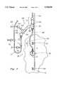
- FIG. 3is a side view of an embodiment of a separator according to this invention.
- FIG. 4is a cross-sectional side view of a detail of the separator embodiment shown in FIG. 3.
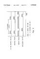
- FIG. 5illustrates an embodiment of a cleaning cycle, graphically represented, that can be used to perform a method according to the invention.
- FIGS. 1 and 2illustrate embodiments of a bioreactor system that can utilize a separator according to this invention.
- the embodiment shown in FIG. 1includes an external separator and the embodiment shown in FIG. 2 includes an internal separator.
- FIGS. 3 and 4illustrate details of one possible embodiment of the system illustrated schematically in FIG. 1.
- FIG. 5illustrates an embodiment of a preferred cleaning cycle.
- bioreactor 10generally designates a fluidized-bed bioreactor adapted for removing contaminants from liquids.
- bioreactor 10includes a reaction chamber 12 adapted to contain a fluidized reactor bed.
- An inlet 14is provided for the introduction of a contaminated waste liquid to be treated in bioreactor 10.
- Representative contaminantsinclude water containing petroleum hydrocarbons, benzene/toluene/ethylbenzene/xylenes (BTEX) and trichloroethylene (TCE), although other contaminants are possible, either alone or in combination.
- An outlet 16is provided for the removal of treated effluent or other liquid.
- the liquid level in reaction chamber 12extends upwardly to an upper level 18.
- a mixer or agitator 20is rotated by means of a motor 22 in order to control the height of the fluidized bed.
- the fluidized bedcomprises a slurry 24 including liquid, a growth media or packing material (such as carbon granules, for example), and biomass.
- a growth media or packing materialsuch as carbon granules, for example
- biomassMany suitable forms of media are known in the art.
- the mediais supplied with microorganisms such as Pseudomonas, Actinomyces, or other bacteria, fungi or molds, for example, which can degrade contaminants carried by the liquid introduced through the inlet. Upon passing into contact with the microorganisms, contaminants within the contaminated liquid are degraded. Degradation of the contaminant occurs by the usual mechanism of the particular microorganisms employed. As the quantity of biomass increases during the bioreaction process, it becomes beneficial to remove some of the biomass that can be considered excess to the bioreaction system. In most instances, the excess biomass includes dead cell mass and residual nutrients and carrier fluid. Frequently, no special disposal procedures or apparatus is required.
- separator 30In order to remove excess biomass from slurry 24, a separator 30 is provided. As shown in FIG. 1, separator 30 is optionally positioned outside of reaction chamber 12. However, as shown in FIG. 2, separator 30 is alternatively positioned within reaction chamber 12, depending upon design choices and the specific application with which the bioreactor is used.
- separator inlet 32is provided for the flow of slurry 24 into separator 30 from the fluidized bed. Separator inlet 32 is optionally a lift, as will be described later. Also provided is a media return 34 through which media returns to the fluidized bed after passing through separator 30. Media return 34 is optionally a media discharge port, as will be described later.
- Separator 30also includes a biomass discharge 36 through which excess biomass removed from slurry 24 is removed from the system. As shown in FIGS. 1 and 2, separator 30 and/or biomass discharge 36 is preferably adjustable in position or height in the direction generally designated "A". This preferred feature, as well as various benefits thereof, is described in detail in co-pending application Ser. No. 08/715,561, incorporated herein by reference.
- FIGS. 3 and 4a particular embodiment of an external separator (such as the one illustrated schematically in FIG. 1, for example) is shown.
- FIG. 3shows an external separator assembly 38 that is connected to the outside of a reaction chamber such as reaction chamber 12.
- Separator assembly 38includes a supply or lift assembly 40, details of which are provided in the cross-sectional view presented in FIG. 4.
- Supply or lift assembly 40is attached to the wall of a reaction chamber by means of a flange 78.
- flange 78Connected to flange 78 is an outlet line 80 and a baffle 82 through which slurry (such as slurry 24 shown in FIGS. 1 and 2) flows from within the reaction chamber in the direction designated "C.”
- a motive fluid supply line 84is provided for the introduction of motive fluid--preferably a motive gas such as air is used, but a motive liquid is contemplated as well.
- the motive fluidwhen in gaseous form, is introduced via supply line 84 (FIG. 4) and creates bubbles that urge the slurry in slugs upwardly through a lift line or passage 42 in the general direction labeled "B".
- Passage 42extends upwardly for connection to a separator body 44.
- Separator body 44is attached to a channel 46 in a manner that permits height adjustability in the direction "A”.
- Separator body 44is attached to channel 46 by means of clamps 48.
- channel 46is attached to the reaction chamber by means of brackets 50. Accordingly, adjustment to the height of separator body 44 can be made easily by moving separator body 44 upwardly or downwardly along channel 46 and, when a desired height is established, fixing separator body 44 with respect to channel 46.
- a tee 52is provided to receive slurry from the passage 42.
- Motive fluidsuch as gas separates from the slurry in a pipe section (not labeled) above tee 52, and such separated fluid is discharged upwardly through vent line 54.
- the slurrywhich arrives in separator body 44 in slugs when motive gas is used, travels from tee 52, through an elbow 56, and arrives at a second tee 58.
- separationoccurs between excess biomass in the slurry and media in the slurry. The separation occurs mostly due to a difference between the density of the biomass and the density of the media. Biomass tends to move upwardly by virtue of a controlled upward velocity, while the media tends to sink.
- a pipe 60extends upwardly at an angle from tee 58 and terminates at an elbow 62 to which a biomass discharge opening 64 and biomass line 66 are connected. As previously described, biomass discharge 64 is most preferably adjusted to a height that provides a desired biomass outflow rate. The length of pipe 60 is optionally adjustable as well to accomplish desired outflow rate. Details are provided in co-pending application Ser. No. 08/715,561.
- a media discharge 70Downstream from tee 58 is provided an elbow 68 which terminates at a media discharge 70. Out through media discharge 70 flows the media that remains in the extracted slurry as well as the majority of liquid from the slurry (it is contemplated that some amount of liquid will be discharged through biomass discharge 64).
- a media return line 72is connected to media discharge 70 through which media returns to the fluidized bed by means of a valved return assembly.
- valve return assembly illustrated in FIG. 3is beneficial for urging media to the fluidized bed.
- An alternative return assemblyis described in co-pending application Ser. No. 08/715,561, which also describes other possible separator details and is therefore incorporated herein by reference.
- the preferred valve return assemblyincludes a media valve 71 positioned downstream from media discharge 70.
- Media valve 71is normally open to permit the flow of media from media discharge 70 into media return line 72. When closed, media valve 71 prevents such flow and also prevents the flow of media back upstream through the discharge from the return line.
- a valveis preferred, any known component for controlling flow is optionally substituted.
- a pumpmay be used as can any other equivalent device. If a valve is used, any type of valve is optionally selected. Also, whatever device is selected, it is optionally adapted for on/off control or for proportional or throttled control.
- media return motive fluid valve 73is connected to a source of pressurized fluid, such as a liquid or gas (not shown) and is normally closed to prevent the flow of such influent into media return line 72.
- a source of pressurized fluidsuch as a liquid or gas (not shown)
- media return motive fluid valve 73introduces pressurized fluid into the return line in order to urge media to the fluidized bed through the return line.
- the pressurized fluidcan be selected from any available liquid or gas, but is most preferably liquid that has already been treated in the bioreactor, liquid yet-to-be treated, or some mixture thereof. Alternatively, water, nutrients, or other materials are used.
- the pressurized fluidis most preferably introduced through a valve, other means are contemplated as described above with respect to the media valve.
- Clean water valve 75is connected to a source of clean water or another suitable cleaning medium (not shown). Valve 75 is normally closed to prevent the flow of cleaning water into media return line 72. When opened, valve 75 introduces cleaning medium such as water into the return line in order to clean the media, preferably in counter-current flow, in the return line.
- valves 71, 73 and 75may be separate valves or any alternative or equivalent means of controlling flow.
- valves 71, 73 and 75are optionally combined into a three-way valve or into one or more multiport valves, in any combination.
- Other combinationsare contemplated.
- a motive fluidsuch as gas or air is injected to urge a portion of slurry through a lift passage.
- Biomassis discharged through a biomass discharge that is preferably maintained at a height above the height of liquid in the reaction chamber.
- Media from the slurryis discharged through a media discharge for return to the fluidized bed by means of a media return line.
- the separation and media return process according to this inventionis preferably performed in periodic cycles, referred to as cleaning cycles herein.
- Each cleaning cyclepreferably includes a cleaning stage during which slurry is delivered to the separator from the fluidized bed and optional cleaning medium is introduced.
- Each cleaning cyclealso preferably includes a flushing stage during which media collected in the media return line is returned to the fluidized bed.
- FIG. 5an embodiment of a cleaning cycle according to this invention is illustrated graphically.
- This figureillustrates a preferred cycle as time progresses to the right along the abscissa. It also illustrates the relative on/off or opened/closed positions of an optional clean water valve (such as valve 75), a motive fluid supply (such as at supply line 84), a media valve (such as valve 71), and a media return motive fluid valve (such as valve 73).
- an optional clean water valvesuch as valve 75
- a motive fluid supplysuch as at supply line 84
- a media valvesuch as valve 71
- a media return motive fluid valvesuch as valve 73
- the clean water valveis preferably opened at the start of the cycle to begin a cleaning stage as motive fluid is introduced. During this cleaning stage, slurry is lifted to the separator from the fluidized bed, biomass is discharged through the biomass discharge, media is discharged through the open media valve into the media return line, and media is cleaned in the return line by the introduced water in counter-current flow.
- the motive fluidis cut off, the clean water valve is closed, the media valve is closed, and the media return motive fluid valve is opened to urge the cleaned media in a downstream direction back to the bioreactor through the return line.
- the cleaning cycleis repeated in periodic intervals or on command as needed.
- the separator assemblycan be located within the reaction chamber or outside the reaction chamber.
- the biomass dischargeis preferably positioned at a height greater than that of the liquid in the reaction chamber, the height of the biomass discharge is preferably adjustable upwardly or downwardly.
- Other possible modificationsare described in co-pending application Ser. No. 08/715,566 and are incorporated herein by reference. Many additional modifications are contemplated.
- a separator and method according to this inventionprovides significant benefits. Specifically, it permits the separation-out of excess biomass that often accumulates during a continuous fluidized-bed bioreaction. Without removing such excess biomass, the performance of the bioreaction system can otherwise be diminished. Accordingly, the separator and method according to this invention provide substantial improvements to the effectiveness of fluidized-bed bioreactors.
Landscapes
- Life Sciences & Earth Sciences (AREA)
- Biodiversity & Conservation Biology (AREA)
- Microbiology (AREA)
- Hydrology & Water Resources (AREA)
- Engineering & Computer Science (AREA)
- Environmental & Geological Engineering (AREA)
- Water Supply & Treatment (AREA)
- Chemical & Material Sciences (AREA)
- Organic Chemistry (AREA)
- Biological Treatment Of Waste Water (AREA)
Abstract
Description
Claims (20)
Priority Applications (1)
| Application Number | Priority Date | Filing Date | Title |
|---|---|---|---|
| US08/715,199US5750028A (en) | 1996-09-18 | 1996-09-18 | Biomass separation apparatus and method with media return |
Applications Claiming Priority (1)
| Application Number | Priority Date | Filing Date | Title |
|---|---|---|---|
| US08/715,199US5750028A (en) | 1996-09-18 | 1996-09-18 | Biomass separation apparatus and method with media return |
Publications (1)
| Publication Number | Publication Date |
|---|---|
| US5750028Atrue US5750028A (en) | 1998-05-12 |
Family
ID=24873044
Family Applications (1)
| Application Number | Title | Priority Date | Filing Date |
|---|---|---|---|
| US08/715,199Expired - LifetimeUS5750028A (en) | 1996-09-18 | 1996-09-18 | Biomass separation apparatus and method with media return |
Country Status (1)
| Country | Link |
|---|---|
| US (1) | US5750028A (en) |
Cited By (9)
| Publication number | Priority date | Publication date | Assignee | Title |
|---|---|---|---|---|
| US5985149A (en)* | 1995-12-08 | 1999-11-16 | Raetz; Richard M. | Bioremediation system |
| US20030036191A1 (en)* | 2001-08-16 | 2003-02-20 | Samuel Frisch | Bed cleaning system for fluidized-bed bioreactors |
| AT410273B (en)* | 2000-05-25 | 2003-03-25 | Herbert Josef Karlsreiter | Apparatus for biodegrading biomass, e.g. grass, has shafts fitted with swiveling plates or rakes for adding or removing material, mat at base absorbing liquid and distributing recycled gas |
| US20050287659A1 (en)* | 2004-06-25 | 2005-12-29 | Samuel Frisch | System and method for separating biomass from media in a fluidized bed reactor |
| US7156985B1 (en) | 2004-07-16 | 2007-01-02 | Shaw Intellectual Property Holdings, Inc. | Bioreactor system having improved temperature control |
| US20070188507A1 (en)* | 2006-02-14 | 2007-08-16 | Akihiro Mannen | Storage control device and storage system |
| US20100210003A1 (en)* | 2009-02-16 | 2010-08-19 | Advanced Lab Group Llc | System and related method for concentrating biological culture and circulating biological culture and process fluid |
| US10888806B2 (en)* | 2013-11-12 | 2021-01-12 | William Bloomfield | Scrubbing backwash filter |
| US12422138B2 (en) | 2019-12-26 | 2025-09-23 | Anellotech, Inc. | Process and apparatus for removing impurities from solid biomass feeds |
Citations (29)
| Publication number | Priority date | Publication date | Assignee | Title |
|---|---|---|---|---|
| US2146326A (en)* | 1935-11-22 | 1939-02-07 | Int Suiker En Alcohol Cie Inte | Process for obtaining alcohol by fermentation of liquids containing carbohydrate |
| US3705082A (en)* | 1968-10-18 | 1972-12-05 | British Petroleum Co | Cultivation and recovery of micro-organisms |
| US3855120A (en)* | 1971-07-09 | 1974-12-17 | P Garbo | Oxygenation of waste water |
| US3910826A (en)* | 1973-01-29 | 1975-10-07 | Dainippon Ink & Chemicals | Cultivation apparatus for micro-organisms |
| US4026674A (en)* | 1975-10-30 | 1977-05-31 | Commonwealth Oil Refining Co., Inc. | Multi-stage reactor |
| US4177144A (en)* | 1978-07-19 | 1979-12-04 | Ecolotrol, Inc. | Excess-growth control system for fluidized-bed reactor |
| US4250033A (en)* | 1979-07-06 | 1981-02-10 | Ecolotrol, Inc. | Excess-growth control system for fluidized-bed reactor |
| US4357424A (en)* | 1979-12-13 | 1982-11-02 | Sim-Chem Limited | Process for the continuous production of fermentation alcohol |
| US4545909A (en)* | 1977-10-20 | 1985-10-08 | The University Of Manchester Institute Of Science And Technology | Growth of biomass |
| US4561974A (en)* | 1983-02-03 | 1985-12-31 | Degremont | Apparatus for the anaerobic filtration of waste water |
| US4589927A (en)* | 1984-05-29 | 1986-05-20 | Battelle Development Corporation | Liquid multisolid fluidized bed processing |
| US4681685A (en)* | 1985-06-25 | 1987-07-21 | Dorr-Oliver Inc. | Method and apparatus for concentrating bioparticles |
| US4707252A (en)* | 1985-08-09 | 1987-11-17 | Societe Degremont | Fluid bed reactor for the biological treatment of water |
| US4708936A (en)* | 1985-02-27 | 1987-11-24 | Lonza Ltd. | Process for the continuous production of L-carnitine |
| US4882068A (en)* | 1988-05-02 | 1989-11-21 | Parkson Corporation | Method and apparatus for removing liquid from suspensions |
| US4892818A (en)* | 1987-02-05 | 1990-01-09 | Floyd Ramp | Bioreactor |
| US4904600A (en)* | 1987-02-05 | 1990-02-27 | Floyd Ramp | Bioreactor for continuous processing of a reactant fluid |
| US4954259A (en)* | 1984-05-23 | 1990-09-04 | Mornex Limited | Process for the treatment and purification of water by the flocculation of suspended particles in a fluidized bed |
| US4959084A (en)* | 1989-05-26 | 1990-09-25 | The United States Of America As Represented By The Administrator Of The National Aeronautics And Space Administration | Combined air and water pollution control system |
| US5166072A (en)* | 1986-06-26 | 1992-11-24 | Bayer Aktiengesellschaft | Apparatus for the cultivation of immobilized micro-organisms |
| US5173194A (en)* | 1989-12-05 | 1992-12-22 | Hering Jr Carl J | Filtration method and apparatus having a filtrate collection chamber within the filter bed |
| US5260216A (en)* | 1990-09-21 | 1993-11-09 | Ajinomoto Co., Inc. | Apparatus for amino acid fermentation |
| US5277829A (en)* | 1992-07-14 | 1994-01-11 | Andritz Sprout-Bauer, Inc. | Deep bed sand filter |
| US5316945A (en)* | 1991-12-14 | 1994-05-31 | Will Minuth | Cell carrier arrangement |
| US5342781A (en)* | 1993-07-15 | 1994-08-30 | Su Wei Wen W | External-loop perfusion air-lift bioreactor |
| US5487829A (en)* | 1994-03-03 | 1996-01-30 | The United States Of America As Represented By The Administrator Of The United States Environmental Protection Agency | Internal media cleaning device for aerobic fluidized bed reactors |
| US5494574A (en)* | 1994-08-09 | 1996-02-27 | Envirogen, Inc. | Mechanically mixed packed bed bioreactor |
| US5573671A (en)* | 1993-12-08 | 1996-11-12 | Hans Brochier Gmbh & Co. | Method of and apparatus for water purification |
| US5573663A (en)* | 1994-01-10 | 1996-11-12 | Junius; John H. | Fluid filter using floating media |
- 1996
- 1996-09-18USUS08/715,199patent/US5750028A/ennot_activeExpired - Lifetime
Patent Citations (30)
| Publication number | Priority date | Publication date | Assignee | Title |
|---|---|---|---|---|
| US2146326A (en)* | 1935-11-22 | 1939-02-07 | Int Suiker En Alcohol Cie Inte | Process for obtaining alcohol by fermentation of liquids containing carbohydrate |
| US3705082A (en)* | 1968-10-18 | 1972-12-05 | British Petroleum Co | Cultivation and recovery of micro-organisms |
| US3717552A (en)* | 1968-10-18 | 1973-02-20 | British Petroleum Co | Apparatus for the cultivation and recovery of microorganisms |
| US3855120A (en)* | 1971-07-09 | 1974-12-17 | P Garbo | Oxygenation of waste water |
| US3910826A (en)* | 1973-01-29 | 1975-10-07 | Dainippon Ink & Chemicals | Cultivation apparatus for micro-organisms |
| US4026674A (en)* | 1975-10-30 | 1977-05-31 | Commonwealth Oil Refining Co., Inc. | Multi-stage reactor |
| US4545909A (en)* | 1977-10-20 | 1985-10-08 | The University Of Manchester Institute Of Science And Technology | Growth of biomass |
| US4177144A (en)* | 1978-07-19 | 1979-12-04 | Ecolotrol, Inc. | Excess-growth control system for fluidized-bed reactor |
| US4250033A (en)* | 1979-07-06 | 1981-02-10 | Ecolotrol, Inc. | Excess-growth control system for fluidized-bed reactor |
| US4357424A (en)* | 1979-12-13 | 1982-11-02 | Sim-Chem Limited | Process for the continuous production of fermentation alcohol |
| US4561974A (en)* | 1983-02-03 | 1985-12-31 | Degremont | Apparatus for the anaerobic filtration of waste water |
| US4954259A (en)* | 1984-05-23 | 1990-09-04 | Mornex Limited | Process for the treatment and purification of water by the flocculation of suspended particles in a fluidized bed |
| US4589927A (en)* | 1984-05-29 | 1986-05-20 | Battelle Development Corporation | Liquid multisolid fluidized bed processing |
| US4708936A (en)* | 1985-02-27 | 1987-11-24 | Lonza Ltd. | Process for the continuous production of L-carnitine |
| US4681685A (en)* | 1985-06-25 | 1987-07-21 | Dorr-Oliver Inc. | Method and apparatus for concentrating bioparticles |
| US4707252A (en)* | 1985-08-09 | 1987-11-17 | Societe Degremont | Fluid bed reactor for the biological treatment of water |
| US5166072A (en)* | 1986-06-26 | 1992-11-24 | Bayer Aktiengesellschaft | Apparatus for the cultivation of immobilized micro-organisms |
| US4892818A (en)* | 1987-02-05 | 1990-01-09 | Floyd Ramp | Bioreactor |
| US4904600A (en)* | 1987-02-05 | 1990-02-27 | Floyd Ramp | Bioreactor for continuous processing of a reactant fluid |
| US4882068A (en)* | 1988-05-02 | 1989-11-21 | Parkson Corporation | Method and apparatus for removing liquid from suspensions |
| US4959084A (en)* | 1989-05-26 | 1990-09-25 | The United States Of America As Represented By The Administrator Of The National Aeronautics And Space Administration | Combined air and water pollution control system |
| US5173194A (en)* | 1989-12-05 | 1992-12-22 | Hering Jr Carl J | Filtration method and apparatus having a filtrate collection chamber within the filter bed |
| US5260216A (en)* | 1990-09-21 | 1993-11-09 | Ajinomoto Co., Inc. | Apparatus for amino acid fermentation |
| US5316945A (en)* | 1991-12-14 | 1994-05-31 | Will Minuth | Cell carrier arrangement |
| US5277829A (en)* | 1992-07-14 | 1994-01-11 | Andritz Sprout-Bauer, Inc. | Deep bed sand filter |
| US5342781A (en)* | 1993-07-15 | 1994-08-30 | Su Wei Wen W | External-loop perfusion air-lift bioreactor |
| US5573671A (en)* | 1993-12-08 | 1996-11-12 | Hans Brochier Gmbh & Co. | Method of and apparatus for water purification |
| US5573663A (en)* | 1994-01-10 | 1996-11-12 | Junius; John H. | Fluid filter using floating media |
| US5487829A (en)* | 1994-03-03 | 1996-01-30 | The United States Of America As Represented By The Administrator Of The United States Environmental Protection Agency | Internal media cleaning device for aerobic fluidized bed reactors |
| US5494574A (en)* | 1994-08-09 | 1996-02-27 | Envirogen, Inc. | Mechanically mixed packed bed bioreactor |
Cited By (15)
| Publication number | Priority date | Publication date | Assignee | Title |
|---|---|---|---|---|
| US5985149A (en)* | 1995-12-08 | 1999-11-16 | Raetz; Richard M. | Bioremediation system |
| AT410273B (en)* | 2000-05-25 | 2003-03-25 | Herbert Josef Karlsreiter | Apparatus for biodegrading biomass, e.g. grass, has shafts fitted with swiveling plates or rakes for adding or removing material, mat at base absorbing liquid and distributing recycled gas |
| US20030036191A1 (en)* | 2001-08-16 | 2003-02-20 | Samuel Frisch | Bed cleaning system for fluidized-bed bioreactors |
| US6706521B2 (en)* | 2001-08-16 | 2004-03-16 | Envirogen, Inc. | Bed cleaning system for fluidized-bed bioreactors |
| US7611890B2 (en) | 2004-06-25 | 2009-11-03 | Samuel Frisch | System and method for separating biomass from media in a fluidized bed reactor |
| US20080213137A1 (en)* | 2004-06-25 | 2008-09-04 | Shaw Intellectual Property Holdings, Inc. | System and method for separating biomass from media in a fluidized bed reactor |
| US7572626B2 (en) | 2004-06-25 | 2009-08-11 | Shaw Intellectual Property Holdings, Inc. | System and method for separating biomass from media in a fluidized bed reactor |
| US20050287659A1 (en)* | 2004-06-25 | 2005-12-29 | Samuel Frisch | System and method for separating biomass from media in a fluidized bed reactor |
| US7156985B1 (en) | 2004-07-16 | 2007-01-02 | Shaw Intellectual Property Holdings, Inc. | Bioreactor system having improved temperature control |
| US20070188507A1 (en)* | 2006-02-14 | 2007-08-16 | Akihiro Mannen | Storage control device and storage system |
| US20100210003A1 (en)* | 2009-02-16 | 2010-08-19 | Advanced Lab Group Llc | System and related method for concentrating biological culture and circulating biological culture and process fluid |
| US8434626B2 (en) | 2009-02-16 | 2013-05-07 | Combined Power, Llc | System and related method for concentrating biological culture and circulating biological culture and process fluid |
| US10888806B2 (en)* | 2013-11-12 | 2021-01-12 | William Bloomfield | Scrubbing backwash filter |
| US11291932B2 (en) | 2013-11-12 | 2022-04-05 | William Bloomfield | Scrubbing backwash filter |
| US12422138B2 (en) | 2019-12-26 | 2025-09-23 | Anellotech, Inc. | Process and apparatus for removing impurities from solid biomass feeds |
Similar Documents
| Publication | Publication Date | Title |
|---|---|---|
| US5227136A (en) | Bioslurry reactor for treatment of slurries containing minerals, soils and sludges | |
| US4259185A (en) | Sludge thickening apparatus | |
| US5779996A (en) | Microbial remediation reactor and process | |
| US7785479B1 (en) | Apparatus and method of separating | |
| US5057284A (en) | Bioslurry reactor for treatment of slurries containing minerals, soils and sludges | |
| US4775467A (en) | Reactor piping with pump column | |
| KR101892276B1 (en) | advanced water treating apparatus using media filtering | |
| US5599450A (en) | Anaerobic upflow batch reactor | |
| US5750028A (en) | Biomass separation apparatus and method with media return | |
| US5788842A (en) | Biomass separation apparatus and method | |
| US4724073A (en) | Reactor piping and flow control system | |
| US4645592A (en) | Reactor piping and flow control system | |
| US6461509B1 (en) | Method and installation for purifying contaminated water | |
| JP3772028B2 (en) | Anaerobic water treatment device | |
| US20070051675A1 (en) | Filter device and method for filtering | |
| US5145589A (en) | Solid-liquid separator and process for washing the same | |
| JP4574830B2 (en) | Sewage treatment apparatus and treatment method | |
| JP2001259674A (en) | Treating device and treating method of sewage | |
| EP1734014A1 (en) | Device and method for filtration of fluids | |
| KR200179035Y1 (en) | Disposal device of waste water with oil | |
| KR100328338B1 (en) | A waste water disposal plant | |
| KR100243646B1 (en) | Apparatus for purifying wastewater | |
| JPH0824516A (en) | Water treatment equipment | |
| KR100239805B1 (en) | Continuous Operation Wastewater Biofiltration Treatment System Using Floating Filter Media | |
| KR200315761Y1 (en) | A precipitator for a nursery to cycle filtration |
Legal Events
| Date | Code | Title | Description |
|---|---|---|---|
| AS | Assignment | Owner name:ENVIROGEN, INC., A CORPORATION OF DELAWARE, NEW JE Free format text:ASSIGNMENT OF ASSIGNORS INTEREST;ASSIGNOR:FRISCH, SAM;REEL/FRAME:008188/0058 Effective date:19960924 | |
| STCF | Information on status: patent grant | Free format text:PATENTED CASE | |
| FPAY | Fee payment | Year of fee payment:4 | |
| FPAY | Fee payment | Year of fee payment:8 | |
| FEPP | Fee payment procedure | Free format text:PAT HOLDER NO LONGER CLAIMS SMALL ENTITY STATUS, ENTITY STATUS SET TO UNDISCOUNTED (ORIGINAL EVENT CODE: STOL); ENTITY STATUS OF PATENT OWNER: SMALL ENTITY | |
| SULP | Surcharge for late payment | ||
| FEPP | Fee payment procedure | Free format text:PAYOR NUMBER ASSIGNED (ORIGINAL EVENT CODE: ASPN); ENTITY STATUS OF PATENT OWNER: SMALL ENTITY | |
| AS | Assignment | Owner name:BASIN WATER, INC., CALIFORNIA Free format text:ASSIGNMENT OF ASSIGNORS INTEREST;ASSIGNORS:SHAW ENVIRONMENTAL & INFRASTRUCTURE, INC.;ENVIROGEN, INC.;REEL/FRAME:022939/0350 Effective date:20080918 Owner name:BASIN WATER, INC.,CALIFORNIA Free format text:ASSIGNMENT OF ASSIGNORS INTEREST;ASSIGNORS:SHAW ENVIRONMENTAL & INFRASTRUCTURE, INC.;ENVIROGEN, INC.;REEL/FRAME:022939/0350 Effective date:20080918 | |
| FPAY | Fee payment | Year of fee payment:12 | |
| FEPP | Fee payment procedure | Free format text:PAT HOLDER CLAIMS SMALL ENTITY STATUS, ENTITY STATUS SET TO SMALL (ORIGINAL EVENT CODE: LTOS); ENTITY STATUS OF PATENT OWNER: SMALL ENTITY | |
| REFU | Refund | Free format text:REFUND - PAYMENT OF MAINTENANCE FEE, 12TH YEAR, LARGE ENTITY (ORIGINAL EVENT CODE: R1553); ENTITY STATUS OF PATENT OWNER: SMALL ENTITY | |
| AS | Assignment | Owner name:ENVIROGEN TECHNOLOGIES, INC., NEW JERSEY Free format text:ASSIGNMENT OF ASSIGNORS INTEREST;ASSIGNOR:BASIN WATER, INC.;REEL/FRAME:024915/0109 Effective date:20090715 | |
| AS | Assignment | Owner name:HSBC BANK PLC, UNITED KINGDOM Free format text:ASSIGNMENT OF ASSIGNORS INTEREST;ASSIGNOR:ENVIROGEN TECHNOLOGIES, INC.;REEL/FRAME:038735/0602 Effective date:20160527 | |
| AS | Assignment | Owner name:ENVIORNGEN TECHNOLOGIES, INC., TEXAS Free format text:RELEASE BY SECURED PARTY;ASSIGNOR:HSBC BANK PLC;REEL/FRAME:047798/0403 Effective date:20181213 |