US5749904A - Electrotherapy method utilizing patient dependent electrical parameters - Google Patents
Electrotherapy method utilizing patient dependent electrical parametersDownload PDFInfo
- Publication number
- US5749904A US5749904AUS08/690,529US69052996AUS5749904AUS 5749904 AUS5749904 AUS 5749904AUS 69052996 AUS69052996 AUS 69052996AUS 5749904 AUS5749904 AUS 5749904A
- Authority
- US
- United States
- Prior art keywords
- patient
- waveform
- phase
- capacitors
- electrical parameter
- Prior art date
- Legal status (The legal status is an assumption and is not a legal conclusion. Google has not performed a legal analysis and makes no representation as to the accuracy of the status listed.)
- Expired - Lifetime
Links
- 238000000034methodMethods0.000titleclaimsabstractdescription48
- 238000001827electrotherapyMethods0.000titleclaimsabstractdescription20
- 230000001419dependent effectEffects0.000titleclaimsabstractdescription16
- 239000003990capacitorSubstances0.000claimsabstractdescription79
- 238000007599dischargingMethods0.000claimsabstractdescription16
- 238000012544monitoring processMethods0.000claimsabstractdescription10
- 238000007493shaping processMethods0.000claimsdescription5
- 230000002051biphasic effectEffects0.000description31
- 230000035939shockEffects0.000description21
- 238000010586diagramMethods0.000description11
- 230000004044responseEffects0.000description8
- 230000007246mechanismEffects0.000description7
- 238000013194cardioversionMethods0.000description5
- 230000008901benefitEffects0.000description4
- 238000013461designMethods0.000description4
- 230000016507interphaseEffects0.000description4
- 208000003663ventricular fibrillationDiseases0.000description4
- 206010049418Sudden Cardiac DeathDiseases0.000description3
- 206010003119arrhythmiaDiseases0.000description3
- 230000006793arrhythmiaEffects0.000description3
- 238000006243chemical reactionMethods0.000description3
- 230000006870functionEffects0.000description3
- 238000005259measurementMethods0.000description3
- 230000004083survival effectEffects0.000description3
- 238000013459approachMethods0.000description2
- 230000008859changeEffects0.000description2
- 238000001514detection methodMethods0.000description2
- 230000000694effectsEffects0.000description2
- 230000000977initiatory effectEffects0.000description2
- 238000002955isolationMethods0.000description2
- 230000035479physiological effects, processes and functionsEffects0.000description2
- 238000012360testing methodMethods0.000description2
- 238000011282treatmentMethods0.000description2
- XUIMIQQOPSSXEZ-UHFFFAOYSA-NSiliconChemical compound[Si]XUIMIQQOPSSXEZ-UHFFFAOYSA-N0.000description1
- 230000017531blood circulationEffects0.000description1
- 230000004087circulationEffects0.000description1
- 230000001862defibrillatory effectEffects0.000description1
- 238000004146energy storageMethods0.000description1
- 238000005516engineering processMethods0.000description1
- 230000036039immunityEffects0.000description1
- 238000002513implantationMethods0.000description1
- 210000001087myotubuleAnatomy0.000description1
- 230000010287polarizationEffects0.000description1
- 229910052710siliconInorganic materials0.000description1
- 239000010703siliconSubstances0.000description1
- 239000007787solidSubstances0.000description1
- 238000001356surgical procedureMethods0.000description1
- 238000002560therapeutic procedureMethods0.000description1
- 210000001519tissueAnatomy0.000description1
Images


Classifications
- A—HUMAN NECESSITIES
- A61—MEDICAL OR VETERINARY SCIENCE; HYGIENE
- A61N—ELECTROTHERAPY; MAGNETOTHERAPY; RADIATION THERAPY; ULTRASOUND THERAPY
- A61N1/00—Electrotherapy; Circuits therefor
- A61N1/18—Applying electric currents by contact electrodes
- A61N1/32—Applying electric currents by contact electrodes alternating or intermittent currents
- A61N1/38—Applying electric currents by contact electrodes alternating or intermittent currents for producing shock effects
- A61N1/39—Heart defibrillators
- A61N1/3925—Monitoring; Protecting
- A61N1/3937—Monitoring output parameters
- A—HUMAN NECESSITIES
- A61—MEDICAL OR VETERINARY SCIENCE; HYGIENE
- A61N—ELECTROTHERAPY; MAGNETOTHERAPY; RADIATION THERAPY; ULTRASOUND THERAPY
- A61N1/00—Electrotherapy; Circuits therefor
- A61N1/18—Applying electric currents by contact electrodes
- A61N1/32—Applying electric currents by contact electrodes alternating or intermittent currents
- A61N1/38—Applying electric currents by contact electrodes alternating or intermittent currents for producing shock effects
- A61N1/39—Heart defibrillators
- A61N1/3906—Heart defibrillators characterised by the form of the shockwave
- A61N1/3912—Output circuitry therefor, e.g. switches
Definitions
- This inventionrelates generally to an electrotherapy method and apparatus for delivering a shock to a patient's heart.
- this inventionrelates to a method and apparatus for shaping the electrical waveform delivered by an external defibrillator based on an electrical parameter measured during delivery of the waveform.
- Sudden cardiac deathis the leading cause of death in the United States. Most sudden cardiac death is caused by ventricular fibrillation, in which the heart's muscle fibers contract without coordination, thereby interrupting normal blood flow to the body. The only effective treatment for ventricular fibrillation is electrical defibrillation, which applies an electrical shock to the patient's heart.
- the defibrillation shockmust be delivered to the patient within minutes of the onset of ventricular fibrillation. Studies have shown that defibrillation shocks delivered within one minute after ventricular fibrillation begins achieve up to 100% survival rate. The survival rate falls to approximately 30% if 6 minutes elapse before the shock is administered. Beyond 12 minutes, the survival rate approaches zero.
- Implantable defibrillatorsare surgically implanted in patients who have a high likelihood of needing electrotherapy in the future. Implanted defibrillators typically monitor the patient's heart activity and automatically supply electrotherapeutic pulses directly to the patient's heart when indicated. Thus, implanted defibrillators permit the patient to function in a somewhat normal fashion away from the watchful eye of medical personnel. Implantable defibrillators are expensive, however, and are used on only a small fraction of the total population at risk for sudden cardiac death.
- External defibrillatorssend electrical pulses to the patient's heart through electrodes applied to the patient's torso. External defibrillators are useful in the emergency room, the operating room, emergency medical vehicles or other situations where there may be an unanticipated need to provide electrotherapy to a patient on short notice.
- the advantage of external defibrillatorsis that they may be used on a patient as needed, then subsequently moved to be used with another patient.
- external defibrillatorsdeliver their electrotherapeutic pulses to the patient's heart indirectly (ie., from the surface of the patients skin rather than directly to the heart), they must operate at higher energies, voltages and/or currents than implanted defibrillators. These high energy, voltage and current requirements have made existing external defibrillators large, heavy and expensive, particularly due to the large size of the capacitors or other energy storage media required by these prior art devices. The size and weight of prior art external defibrillators have limited their utility for rapid response by emergency medical response teams.
- Defibrillator waveformsie., time plots of the delivered current or voltage pulses, are characterized according to the shape, polarity, duration and number of pulse phases. Most current external defibrillators deliver monophasic current or voltage electrotherapeutic pulses, although some deliver biphasic sinusoidal pulses. Some prior art implantable defibrillators, on the other hand, use truncated exponential, biphasic waveforms. Examples of biphasic implantable defibrillators may be found in U.S. Pat. No. 4,821,723 to Baker, Jr., et al.; U.S. Pat. No. 5,083,562 to de Coriolis et al.; U.S. Pat. No.
- each implanted defibrillatoris dedicated to a single patient, its operating parameters, such as electrical pulse amplitudes and total energy delivered, may be effectively titrated to the physiology of the patient to optimize the defibrillator's effectiveness.
- the initial voltage, first phase duration and total pulse durationmay be set when the device is implanted to deliver the desired amount of energy or to achieve a desired start and end voltage differential (i.e., a constant tilt).
- external defibrillator electrodesare not in direct contact with the patient's heart, and because external defibrillators must be able to be used on a variety of patients having a variety of physiological differences, external defibrillators must operate according to pulse amplitude and duration parameters that will be effective in most patients, no matter what the patient's physiology.
- the impedance presented by the tissue between external defibrillator electrodes and the patient's heartvaries from patient to patient, thereby varying the intensity and waveform shape of the shock actually delivered to the patient's heart for a given initial pulse amplitude and duration.
- Pulse amplitudes and durations effective to treat low impedance patientsdo not necessarily deliver effective and energy efficient treatments to high impedance patients.
- External defibrillatorsmay be subjected to extreme load conditions which could potentially damage the waveform generator circuits.
- improperly applied defibrillator electrodesmay create a very low impedance current path during the shock delivery, which could result in excessively high current within the waveform circuit.
- an external defibrillatorhas an additional design requirement to limit the peak current to safe levels in the waveform circuit, which is not normally a concern for implanted defibrillators.
- Prior art defibrillatorshave not fully addressed the patient variability problem.
- One prior art approach to this problemwas to provide an external defibrillator with multiple energy settings that could be selected by the user.
- a common protocol for using such a defibrillatorwas to attempt defibrillation at an initial energy setting suitable for defibrillating a patient of average impedance, then raise the energy setting for subsequent defibrillation attempts in the event that the initial setting failed. The repeated defibrillation attempts require additional energy and add to patient risk.
- Some prior art defibrillatorsmeasure the patient impedance, or a parameter related to patient impedance and alter the shape of a subsequent defibrillation shock based on the earlier measurement.
- the implanted defibrillator described in the Fain patentdelivers a defibrillation shock of predetermined shape to the patient's heart in response to a detected arrhythmia.
- the Fain devicemeasures the system impedance during delivery of that shock and uses the measured impedance to alter the shape of a subsequently delivered shock.
- the defibrillatorhas an energy source that may be discharged through electrodes on the patient to provide a biphasic voltage or current pulse.
- the first and second phase duration and initial first phase amplitudeare predetermined values.
- the duration of the first phase of the pulsemay be extended if the amplitude of the first phase of the pulse fails to fall to a threshold value by the end of the predetermined first phase duration, as might occur with a high impedance patient.
- the first phaseends when the first phase amplitude drops below a threshold value or when the first phase duration reaches a threshold time value, whichever comes first, as might occur with a low to average impedance patient.
- the inventionprovides a method for delivering electrotherapy to a patient through electrodes connected to a plurality of capacitors, including the steps of discharging at least one of the capacitors across the electrodes to deliver electrical energy to the patient, monitoring a patient-dependent electrical parameter (such as voltage, current or charge) during the discharging step, and adjusting energy delivered to the patient based on a value of the electrical parameter.
- the adjusting stepmay include selecting a serial or parallel arrangement for the capacitors based on a value of the electrical parameter.
- the inventionprovides a method for delivering electrotherapy to a patient through electrodes connectable to a plurality of capacitors including the steps of discharging at least one of the capacitors across the electrodes to deliver electrical energy to the patient in a waveform having at least a first phase and a second phase, monitoring a patient-dependent electrical parameter (such as voltage, current or charge) during the discharging step, and modifying second phase initial voltage based on a value of the electrical parameter.
- the adjusting stepmay include selecting a serial or a parallel arrangement for the capacitors based on a value of the electrical parameter.
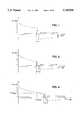
- FIG. 1is a schematic representation of a low-tilt biphasic electrotherapeutic waveform according to a first aspect of this invention.
- FIG. 2is a schematic representation of a high-tilt biphasic electrotherapeutic waveform according to the first aspect of this invention.
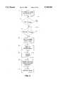
- FIG. 3is a flow chart demonstrating part of an electrotherapy method according to a second aspect of this invention.
- FIG. 4is a schematic representation of a biphasic waveform delivered according to the second aspect of this invention.
- FIG. 5is a schematic representation of a biphasic waveform delivered according to the second aspect of this invention.
- FIG. 6is a flow chart demonstrating part of an electrotherapy method according to a third aspect of this invention.
- FIG. 7is a schematic representation of a biphasic waveform delivered according to the third aspect of this invention.
- FIG. 8is a schematic representation of a biphasic waveform delivered according to the third aspect of this invention.
- FIG. 9is a flow chart demonstrating part of an electrotherapy method according to a combination of the second and third aspects of this invention.
- FIG. 10is a block diagram of a defibrillator system according to a preferred embodiment of this invention.
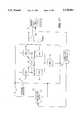
- FIG. 11is a schematic circuit diagram of a defibrillator system according to a preferred embodiment of this invention.
- FIG. 12is a block diagram showing another embodiment of the external defibrillator system of this invention.
- FIG. 13is a schematic diagram of a defibrillator system according to a preferred embodiment of this invention.
- FIG. 14is a schematic diagram of yet another embodiment of this invention.
- FIG. 15is a schematic representation of a biphasic waveform delivered by the external defibrillator shown in FIG. 14.
- FIG. 16is a schematic diagram of another embodiment of this invention.
- FIG. 17is a schematic diagram of yet another embodiment of this invention.
- FIGS. 1 and 2illustrate the patient-to-patient differences that an external defibrillator design must take into account.
- These figuresare schematic representations of truncated exponential biphasic waveforms delivered to two different patients from an external defibrillator according to the electrotherapy method of this invention for defibrillation or cardioversion.
- the vertical axisis voltage
- the horizontal axisis time. The principles discussed here are applicable to waveforms described in terms of current versus time as well, however.
- the waveform shown in FIG. 1is called a low-tilt waveform, and the waveform shown in FIG. 2 is called a high-tilt waveform, where tilt H is defined as a percent as follows: ##EQU1##
- Ais the initial first phase voltage
- Dis the second phase terminal voltage.
- the first phase terminal voltage Bresults from the exponential decay over time of the initial voltage A through the patient
- the second phase terminal voltage Dresults from the exponential decay of the second phase initial voltage C in the same manner.
- the starting voltages and first and second phase durations of the FIG. 1 and FIG. 2 waveformsare the same; the differences in end voltages B and D reflect differences in patient impedance.
- Low-tilt biphasic waveformsachieve effective defibrillation rates with less delivered energy than high-tilt waveforms.
- low-tilt waveformsare energy inefficient, since much of the stored energy is not delivered to the patient.
- defibrillators delivering high-tilt biphasic waveformsdeliver more of the stored energy to the patient than defibrillators delivering low-tilt waveforms while maintaining high efficacy up to a certain critical tilt value.
- high impedance patientsreceive a waveform with less total energy and lower peak currents but better conversion properties per unit of energy delivered
- low impedance patientsreceive a waveform with more delivered energy and higher peak currents.
- An optimum capacitor charged to a predetermined voltagecan be chosen to deliver an effective and efficient waveform across a population of patients having a variety of physiological differences.
- This inventionis a defibrillator and defibrillation method that takes advantage of this relationship between waveform tilt and total energy delivered in high and low impedance patients.
- the defibrillatoroperates in an open loop, i.e., without any feedback regarding patient impedance parameters and with preset pulse phase durations.
- the preset parameters of the waveforms shown in FIG. 1 and 2are therefore the initial voltage A of the first phase of the pulse, the duration E of the first phase, the interphase duration G, and the duration F of the second phase.
- the terminal voltage B of the first phase, the initial voltage C of the second phase, and the terminal voltage D of the second phaseare dependent upon the physiological parameters of the patient and the physical connection between the electrodes and the patient.
- the patient impedanceie., the total impedance between the two electrodes
- the amount of voltage drop (exponential decay) from the initial voltage A to the terminal voltage B during time Ewill be lower (FIG. 1) than if the patient impedance is low (FIG. 2).
- the sameis true for the initial and terminal voltages of the second phase during time F.
- the values of A, E, G and Fare set to optimize defibrillation and/or cardioversion efficacy across a population of patients.
- high impedance patientsreceive a low-tilt waveform that is more effective per unit of delivered energy
- low impedance patientsreceive a high-tilt waveform that delivers more of the stored energy and is therefore more energy efficient.
- FIGS. 3-5demonstrate a defibrillation method according to this second aspect of the invention in which information related to patient impedance is fed back to the defibrillator to change the parameters of the delivered electrotherapeutic pulse.
- FIG. 3is a flow chart showing the method steps following the decision (by an operator or by the defibrillator itself) to apply an electrotherapeutic shock to the patient through electrodes attached to the patient and charging of the energy source, e.g., the defibrillator's capacitor or capacitor bank, to the initial first phase voltage A.
- Block 10represents initiation of the first phase of the pulse in a first polarity. Discharge may be initiated manually by the user or automatically in response to patient heart activity measurements (e.g., ECG signals) received by the defibrillator through the electrodes and analyzed by the defibrillator controller in a manner known in the art.
- patient heart activity measurementse.g., ECG signals
- Discharge of the first phasecontinues for at least a threshold time t THRESH , as shown by block 12 of FIG. 3. If, at the end of time t THRESH , the voltage measured across the energy source has not dropped below the minimum first phase terminal voltage threshold V THRESH , first phase discharge continues, as shown in block 14 of FIG. 3. For high impedance patients, this situation results in an extension of the first phase duration beyond V THRESH , as shown in FIG. 4, until the measured voltage drops below the threshold V THRESH . Discharge then ends to complete the first phase, as represented by block 16 of FIG. 3. If, on the other hand, the patient has low impedance, the voltage will have dropped below V THRESH when the time threshold is reached, resulting in a waveform like the one shown in FIG. 5.
- the polarity of the energy source connection to the electrodesis switched, as represented by blocks 18 and 20 of FIG. 3.
- Discharge of the second phase of the biphasic pulsethen commences and continues for a predetermined second phase duration F, as represented by block 22 of FIG. 3, then ceases.
- This compensating electrotherapy methodensures that the energy is delivered by the defibrillator in the most efficacious manner by providing for a minimum waveform tilt and by extending the first phase duration to meet the requirements of a particular patient.
- the defibrillator's energy sourcecan be smaller than in prior art external defibrillators, thereby minimizing defibrillator size, weight and expense. It should be noted that the waveforms shown in FIGS. 4 and 5 could be expressed in terms of current versus time using a predetermined current threshold value without departing from the scope of the invention.
- FIGS. 6-8illustrate a third aspect of this invention that prevents the delivered waveform from exceeding a maximum tilt (i.e., maximum delivered energy) in low impedance patients.
- the first phase dischargestops either at the end of a predetermined time t THRESH or when the first phase voltage drops below V' THRESH .
- the second phasebegins after an interim period G and continues for a preset period F as in the second aspect of the invention.
- the first phaseends at time t THRESH , even if the voltage has not yet fallen below V' THRESH , as shown in FIG. 7.
- the first phase of the delivered waveformcould be shorter in duration than the time t THRESH , as shown in FIG. 8.
- FIG. 9is a flow chart illustrating a combination of the defibrillation methods illustrated in FIGS. 3 and 6.
- the first phase of the biphasic waveformwill end if the voltage reaches a first voltage threshold V' THRESH prior to the first phase duration threshold T THRESH , as shown by blocks 91 and 92.
- This defibrillator decision pathdelivers a waveform like that shown in FIG. 8 for low impedance patients.
- the second phase pulsecould be a function of the first phase voltage, current or time instead of having a fixed time duration.
- any of the above embodimentscould provide for alternating initial polarities in successive monophasic or biphasic pulses.
- the first biphasic waveform delivered by the systemthe first phase is a positive voltage or current pulse followed by a second phase negative voltage or current pulse
- the second biphasic waveform delivered by the systemwould be a negative first phase voltage or current pulse followed by a positive second phase voltage or current pulse. This arrangement would minimize electrode polarization, ie., build-up of charge on the electrodes.
- the initial first phase voltage Amay be the same for all patients or it may be selected automatically or by the defibrillator user.
- the defibrillatormay have a selection of initial voltage settings, one for an infant, a second for an adult, and a third for use in open heart surgery.
- the defibrillatormay deliver a waveform that has a minimum voltage or current at the beginning and/or at the end of a waveform phase.
- FIG. 10is a schematic block diagram of a defibrillator system according to a preferred embodiment of this invention.
- the defibrillator system 30comprises an energy source 32 to provide the voltage or current pulses described above.
- energy source 32is a single capacitor or a capacitor bank arranged to act as a single capacitor.
- a connecting mechanism 34selectively connects and disconnects energy source 32 to and from a pair of electrodes 36 electrically attached to a patient, represented here as a resistive load 37.
- the connections between the electrodes and the energy sourcemay be in either of two polarities with respect to positive and negative terminals on the energy source.
- the defibrillator systemis controlled by a controller 38.
- controller 38operates the connecting mechanism 34 to connect energy source 32 with electrodes 36 in one of the two polarities or to disconnect energy source 32 from electrodes 36.
- Controller 38receives timing information from a timer 40, and timer 40 receives electrical information from electrical sensor 42 connected across energy source 32.
- sensor 42is a voltage sensor; in other preferred embodiments, sensor 42 is a current sensor.
- FIG. 11is a schematic circuit diagram illustrating a device according to the preferred embodiments discussed above.
- Defibrillator controller 70activates a high voltage power supply 72 to charge storage capacitor 74 via diode 76 to a predetermined voltage.
- switches SW1, SW2, SW3 and SW4are turned off so that no voltage is applied to the patient (represented here as resistor 78) connected between electrodes 80 and 82.
- SW5is turned on during this time.
- controller 70de-activates supply 72 and activates biphase switch timer 84.
- Timer 84initiates discharge of the first phase of the biphasic waveform through the patient in a first polarity by simultaneously turning on switches SW1 and SW4 via control signals T1 and T4, while switch SW5 remains on to deliver the initial voltage A through electrodes 80 and 82 to the patient 78.
- delivery of the first phase of the biphasic pulsemay be terminated by the timer 84 after the end of a predetermined period or when the voltage across the electrodes has dropped below a predetermined value as measured by comparator 86.
- Timer 84terminates pulse delivery by turning off switch SW5 via control signal T5, followed by turning off switches SW1 and SW4. The voltage across electrodes 80 and 82 then returns to zero.
- timer 84initiates delivery of the second phase by simultaneously turning on switches SW2 and SW3 via control signals T2 and T3 while switch SW5 remains on.
- This configurationapplies voltage from the capacitor to the electrodes at an initial second phase voltage C and in a polarity opposite to the first polarity.
- Timer 84terminates delivery of the second phase by turning off switch SW5 via control signal T5, followed by turning off switches SW2 and SW3.
- the second phasemay be terminated at the end of a predetermined period or when the voltage measured by comparator 86 drops below a second phase termination voltage threshold.
- switch SW5is an insulated gate bipolar transistor (IGBT) and switches SW1-SW4 are silicon-controlled rectifiers (SCRs).
- the SCRsare avalanche-type switches which can be turned on to a conductive state by the application of a control signal, but cannot be turned off until the current through the switch falls to zero or near zero.
- the five switchescan be configured so that any of the switches SW1-SW4 will close when SW5 is closed and will reopen only upon application of a specific control signal to SW5.
- switch SW5does not need to withstand the maximum capacitor voltage.
- the maximum voltage that will be applied across switch SW5will occur when the first phase is terminated by turning SW5 off, at which time the capacitor voltage has decayed to some fraction of its initial value.
- FIGS. 10 and 11may be used to deliver electric pulses of any polarity, amplitude, and duration singly and in any combination.
- FIG. 12is a block diagram showing another embodiment of the defibrillator system of this invention.
- the defibrillator system 90comprises an energy source 92 to provide a voltage or current pulse.
- energy source 92is a single capacitor or a capacitor bank arranged to act as a single capacitor.
- a connecting mechanism 94selectively connects and disconnects a pair of electrodes 96 electrically attached to a patient (represented here as a resistive load 97) to and from the energy source.
- the connections between the electrodes and the energy sourcemay be in either of two polarities with respect to positive and negative terminals on the energy source.
- the defibrillator systemis controlled by a controller 98.
- controller 98operates the connecting mechanism 94 to connect energy source 92 with electrodes 96 in one of the two polarities or to disconnect energy source 92 from electrodes 96.
- Controller 98receives discharge information (such as current, charge and/or voltage) from the discharge circuit.
- Controller 98may also receive timing information from a timer 99.
- Controller 98uses information from the discharge circuit and/or the timer to control the shape of the waveform delivered to the patient in real time (i.e., during delivery of the waveform), such as by selecting appropriate waveform parameters from a memory location associated with the controller or by otherwise adjusting the duration of the phases of the biphasic waveform.
- the systemcontrols the duration, tilt and total delivered energy of the waveform. For example, biphasic waveforms with relatively longer first phases have better conversion properties than waveforms with equal or shorter first phases, provided the total duration exceeds a critical minimum.
- the duration of the first phase of the biphasic waveformmay be desirable to increase the duration of the first phase of the biphasic waveform relative to the duration of the second phase to increase the overall efficacy of the electrotherapy by delivering a more efficacious waveform and to increase the total amount of energy delivered.
- FIG. 13A preferred embodiment of a defibrillator system according to the invention is shown schematically in FIG. 13.
- the energy sourceis a capacitor 92 preferably having a size between 60 and 150 microfarads, most preferably 100 microfarads.
- the systemalso includes a charging mechanism (not shown) for charging the capacitor to an initial voltage.
- a controller 98controls the operation of the defibrillator to deliver a shock to the patient 97 through electrodes 96 automatically in response to a detected arrhythmia or manually in response to a human operator.
- FIG. 13shows an ECG system 100 attached to the electrodes to provide ECG monitoring and/or arrhythmia detection.
- FIG. 13also shows a pair of switches 102 and 104 isolating the patient and the ECG system from the defibrillation circuitry.
- Switches 102 and 104may be any suitable kind of isolators, such as mechanical relays, solid state devices, spark gaps, or other gas discharge devices.
- the ECG system and the isolation switchesare not essential parts of this invention.
- the connecting mechanism 94includes four switches 106, 108, 110 and 112 operated by the controller 98 to deliver a shock from the energy source 92 to the patient.
- the preferred embodimentalso may include an optional current limiting circuit comprising a resistor 114 and switch 116 to provide additional protection to the defibrillator circuit components and to the defibrillator operator. The operation of the isolation switches and the connecting mechanism to deliver a waveform to the patient is described below.
- switches 106, 112 and 116could start out in the closed position, with the operating sequence of the switches modified accordingly.
- the controllerIn response to a request for a shock, the controller first closes switches 102 and 104, then switch 112, then switch 108 to initiate delivery of a limited shock to the patient.
- a current sensor 118monitors the current delivered by the capacitor. If the peak current is below a circuit safety threshold, then switch 116 is closed to take safety resistor 114 out of the circuit. Peak current values above the threshold could indicate a short circuit condition.
- the duration of the first and second phases of the biphasic waveformare determined by measuring a patient-dependent electrical parameter.
- the measured parameter in the preferred embodimentis the time it takes for a predetermined amount of charge to be delivered by the energy source to the patient.
- Charge controlcan provide better noise immunity than other waveform monitoring methods, such as voltage or current monitoring.
- the system shown in FIG. 13uses a current integrator 120 to provide charge information to the controller.
- the controllersets the duration of the first and second waveform phases (thereby controlling the waveform shape) based on charge information from current integrator 120.
- Other means of determining phase durationsmay be used, of course, without departing from the scope of the invention.
- the controlleropens switch 112 to terminate delivery of the shock.
- Switch 116may also be opened at any time from this point on.
- the controlleropens switch 108 as well.
- the controllercloses switches 106 and 110 to initiate delivery of the second phase of the waveform.
- the second phase durationis determined by the first phase duration. Other means of determining second phase duration are within the scope of the invention, however.
- the controlleropens switch 106 to terminate delivery of the shock. Switches 110, 102 and 104 are opened thereafter.
- switches 102 and 104are implemented as a double pole, double throw mechanical relay.
- Switches 108 and 110are each implemented as a pair of SCR's in series in order to meet required standoff voltages with currently available components.
- Switch 106is implemented as two insulated gate bipolar transistors ("IGBT's") in series, again due to high voltage requirements.
- switches 116 and 112are shared among three IGBT's to meet voltage standoff requirements, with one IGBT being on at the same time as switch 116 and off at the same time as switch 112.
- resistor 114is split into two resistors to equally divide the voltage across the IGBT's.
- the current sensor 118may be used to send current information to the controller for purposes of, e.g., short circuit protection, leads off detection, etc. The manner in which the short circuit or leads off conditions are detected are beyond the scope of this invention.
- the integrator 120 and current sensor 118may each be an op-amp feeding a threshold comparator for detecting charge and current limits, respectively.
- the integratorcould be provided with a switch for resetting to initial conditions prior to a waveform delivery.
- a comparator associated with the current integratormonitors the charge delivered to the patient and sends a signal to the waveform controller when the charge reaches 0.06182 Coulombs (referred to as "Qt").
- the time required to reach that charge(“t(Qt)”) is monitored by the controller using an up/down counter which counts a scaled down reference frequency.
- One element of the frequency scaleris a selectable 2:3 pre-scaler.
- the pre-scaleris set to 3 during the first phase.
- eleven time thresholdsare stored in the controller, which determines the first phase duration ("t( ⁇ 1)") based on the time required to reach Qt. At each time threshold, a new value of t( ⁇ 1) is loaded until Qt is reached. If Qt is not reached within 6.35 mS, then t( ⁇ 1) is set to 12 mS.
- the counterruns at the scaled down frequency during delivery of the entire first phase.
- the interphase delayis set at 300 82 S.
- the first phase IGBT'sare opened, terminating the first phase.
- the second phase IGBT'sare closed.
- the second phase SCR'sare closed, initiating the second phase.
- second phase timingis determined by first phase timing. Specifically, the count value accumulated during phase one (2.3 mS to 12 mS) is used to control the duration of the second phase.
- the counter that had been counted up during the first phaseis counted down to 0, at which time the second phase is terminated.
- the actual duration of the second phasedepends on the scaled down frequency used to run down the counter. If the first phase t(Qt) was less than 3.07 mS, then the reference clock prescaler is set to 3 to a give second phase duration equal to the first phase duration. If t(Qt) is greater than or equal to 3.07 mS, then the pre-scaler is set to 2, giving a second phase duration which is 2/3 of the first phase duration.
- the measured patient-dependent electrical parameteris capacitor voltage.
- a comparatormonitors the capacitor voltage and sends a signal to the waveform controller when the voltage decays to 1000 volts (Vt).
- Vt1000 volts
- the time required to reach that voltageis monitored by the controller using an up/down counter which counts a scaled down reference frequency.
- the first phase duration (t( ⁇ 1))is based on the time required to reach Vt.
- the method of selecting the appropriate t( ⁇ 1)is identical to the charge control embodiment. If Vt is not reached within 6.18 mS, then t( ⁇ 1) is set to 12 mS. Table II shows the t(Vt) thresholds and their associated t( ⁇ 1).
- Interphase delay and second phase timingis identical to the charge control method.
- FIG. 14Yet another embodiment of the invention is shown in FIG. 14.
- the energy source for the external defibrillator 130 of FIG. 14is a battery 132 providing power (via a charging device 134) to two capacitors 136 and 138 under the control of controller 140.
- Controller 140also controls switches 144-154 to deliver energy from capacitors 136 and/or 138 to a patient (represented in FIG. 14 by resistor 160) through electrodes 156 and 158.
- the embodiment of FIG. 14may also include a safety resistor 164 and a safety resistor switch 166 to limit the current delivered by the capacitor(s) until it can be determined whether a short circuit condition exists, as discussed above.
- a sensor 162which is preferably either a current sensor or a voltage sensor, monitors a patient-dependent electrical parameter and sends information regarding the monitored parameter to controller 140.
- the arrangement of the capacitors and switches in the embodiment of FIG. 14permits the defibrillator to modify the parameters of the delivered waveform to compensate for patient-to-patient impedance differences, as monitored by sensor 162. For example, if the patient's impedance is high (e.g., over 125 ⁇ ), the defibrillator could deliver a truncated exponential biphasic waveform as follows: (1) Deliver the first phase with switches 145, 146, 166 (assuming the device has determined there is no short circuit), 150 and 152 closed and switches 144, 148, 154 open.
- Capacitors 136 and 138are thus connected in parallel.
- Monitor a patient-dependent electrical parametersuch as voltage, current or charge
- a patient-dependent electrical parametersuch as voltage, current or charge
- the patient-dependent electrical parameterindicates that the electrodes are connected to a high-impedance patient
- the resulting waveformhas a shape similar to that shown in FIG. 15. Note that the leading edge of the second phase of the waveform has a higher voltage than the trailing edge of the first phase.
- the defibrillatorcould deliver a truncated exponential biphasic waveform using only capacitor 136 by keeping switches 144 and 146 open from the start of waveform delivery (if the patient's impedance is known before waveform delivery begins) or by opening switches 144 and 146 shortly after waveform delivery begins to remove capacitor 136 from the circuit.
- the defibrillatorcould deliver a waveform with capacitors 136 and 138 arranged in series from the start of waveform delivery (if the patient's impedance is known before waveform delivery begins) or by opening switches 145 and 146 and closing switch 144 shortly after waveform delivery begins.
- the defibrillatorcould use information regarding patient impedance gathered prior to waveform delivery (such as during a prior waveform delivery) to determine the position of the switches and the configuration of the capacitors.
- FIG. 14uses two capacitors, any number of capacitors greater than one could be used without departing from the scope of the invention.
- FIG. 16is a schematic drawing of another embodiment of this invention. (Elements common with the FIG. 14 embodiment have been given the same element numbers.)
- three capacitors 208, 210, and 212are connectable in series via a three-way switch 206. In the position shown in FIG. 16 (i.e., at switch position 208), only capacitor 200 is connected to the external defibrillator waveform delivery circuit. If switch 206 is at switch position 210, capacitors 200 and 202 are connected to the waveform delivery circuit in series. Finally, if switch 206 is at switch position 212, all three capacitors are connected to the waveform delivery circuit in series.
- an optional three-way switch 201can be positioned to charge only capacitor 200 (when configured as shown), capacitors 200 and 202 together, or all capacitors together. Alternatively, all capacitors could be charged together each time, even if fewer than all capacitors will be discharged to treat a patient.
- the capacitors in FIG. 16can be configured to provide an optimal voltage or current (and thereby optimal energy) to the patient.
- the capacitorsmay be arranged during delivery of the waveform based on a value of a patient-dependent electrical parameter (such as voltage, current or charge) as monitored by sensor 162, e.g., by adjusting the initial voltage or current of a phase of a multiphasic waveform.
- a patient-dependent electrical parametersuch as voltage, current or charge
- the external defibrillatorcould use information regarding patient impedance gathered prior to waveform delivery (such as during a prior waveform delivery) to determine the position of the switch 206 and the configuration of the capacitors. It should be understood that any number of capacitors may be used in the serial capacitor arrangement of FIG. 16. The greater the number of capacitors, the more likely the waveform delivered by the external defibrillator will be titrated to be most efficacious for a particular patient.
- FIG. 17Yet another embodiment of the invention is shown in FIG. 17.
- three capacitors 220, 222 and 224are arranged in parallel.
- switches 228 and 226in the open position as shown in FIG. 17, only capacitor 224 will provide energy to the external defibrillator waveform delivery circuit.
- switch 228could be closed by controller 140 to add capacitor 222 to the circuit.
- switch 226could be closed by controller 140 to place all three capacitors in a parallel arrangement within the waveform delivery circuit.
- the positions of the switches and the arrangement of the capacitorscan be adjusted during waveform delivery, based on a value of a patient-dependent electrical parameter monitored by sensor 162. Alternatively, the optimal switch positions (and therefore optimal energy delivery and/or waveform phase durations) can be determined prior to delivery of the waveform.
Landscapes
- Health & Medical Sciences (AREA)
- Cardiology (AREA)
- Heart & Thoracic Surgery (AREA)
- Engineering & Computer Science (AREA)
- Biomedical Technology (AREA)
- Nuclear Medicine, Radiotherapy & Molecular Imaging (AREA)
- Radiology & Medical Imaging (AREA)
- Life Sciences & Earth Sciences (AREA)
- Animal Behavior & Ethology (AREA)
- General Health & Medical Sciences (AREA)
- Public Health (AREA)
- Veterinary Medicine (AREA)
- Electrotherapy Devices (AREA)
- Finger-Pressure Massage (AREA)
Abstract
Description
TABLE I ______________________________________ If t(Qt) < (mS) Then t(φ1) is (mS) ______________________________________ 1.13 2.3 1.60 2.85 2.07 3.79 2.56 4.02 3.07 4.83 3.58 6.76 4.10 7.73 4.64 8.69 5.20 9.66 5.77 10.62 6.35 11.59 ______________________________________
TABLE II ______________________________________ If t(Vt) < (mS) Then t(φ1) is (mS) ______________________________________ 1.24 2.3 1.73 2.85 2.23 3.79 2.72 4.02 3.22 4.83 3.71 6.76 4.20 7.73 4.70 8.69 5.19 9.66 5.69 10.62 6.18 11.59 ______________________________________
Claims (17)
Priority Applications (1)
| Application Number | Priority Date | Filing Date | Title |
|---|---|---|---|
| US08/690,529US5749904A (en) | 1993-08-06 | 1996-07-31 | Electrotherapy method utilizing patient dependent electrical parameters |
Applications Claiming Priority (3)
| Application Number | Priority Date | Filing Date | Title |
|---|---|---|---|
| US10383793A | 1993-08-06 | 1993-08-06 | |
| US08/227,553US5607454A (en) | 1993-08-06 | 1994-04-14 | Electrotherapy method and apparatus |
| US08/690,529US5749904A (en) | 1993-08-06 | 1996-07-31 | Electrotherapy method utilizing patient dependent electrical parameters |
Related Parent Applications (2)
| Application Number | Title | Priority Date | Filing Date |
|---|---|---|---|
| US10383793AContinuation-In-Part | 1993-08-06 | 1993-08-06 | |
| US08/227,553Continuation-In-PartUS5607454A (en) | 1993-08-06 | 1994-04-14 | Electrotherapy method and apparatus |
Publications (1)
| Publication Number | Publication Date |
|---|---|
| US5749904Atrue US5749904A (en) | 1998-05-12 |
Family
ID=26800907
Family Applications (3)
| Application Number | Title | Priority Date | Filing Date |
|---|---|---|---|
| US08/227,553Expired - LifetimeUS5607454A (en) | 1993-08-06 | 1994-04-14 | Electrotherapy method and apparatus |
| US08/690,529Expired - LifetimeUS5749904A (en) | 1993-08-06 | 1996-07-31 | Electrotherapy method utilizing patient dependent electrical parameters |
| US08/824,713Expired - LifetimeUS5803927A (en) | 1993-08-06 | 1997-02-19 | Electrotherapy method and apparatus for external defibrillation |
Family Applications Before (1)
| Application Number | Title | Priority Date | Filing Date |
|---|---|---|---|
| US08/227,553Expired - LifetimeUS5607454A (en) | 1993-08-06 | 1994-04-14 | Electrotherapy method and apparatus |
Family Applications After (1)
| Application Number | Title | Priority Date | Filing Date |
|---|---|---|---|
| US08/824,713Expired - LifetimeUS5803927A (en) | 1993-08-06 | 1997-02-19 | Electrotherapy method and apparatus for external defibrillation |
Country Status (10)
| Country | Link |
|---|---|
| US (3) | US5607454A (en) |
| EP (2) | EP0712321B1 (en) |
| JP (4) | JPH09500309A (en) |
| AT (1) | ATE263598T1 (en) |
| AU (1) | AU7367294A (en) |
| CA (1) | CA2168978A1 (en) |
| DE (2) | DE69433686T2 (en) |
| ES (1) | ES2215998T3 (en) |
| NO (1) | NO960470L (en) |
| WO (1) | WO1995005215A2 (en) |
Cited By (85)
| Publication number | Priority date | Publication date | Assignee | Title |
|---|---|---|---|---|
| US6198967B1 (en)* | 1996-07-01 | 2001-03-06 | Survivalink Corporation | Continual waveform shape reforming method and apparatus for transchest resistance dynamics |
| US6241751B1 (en) | 1999-04-22 | 2001-06-05 | Agilent Technologies, Inc. | Defibrillator with impedance-compensated energy delivery |
| US6266562B1 (en) | 1999-04-30 | 2001-07-24 | Agilent Technologies, Inc. | Defibrillator with automated test load |
| US6298266B1 (en) | 1999-08-10 | 2001-10-02 | Intermedics Inc. | Methods and apparatus for treating fibrillation and creating defibrillation waveforms |
| WO2001064281A3 (en)* | 2000-03-01 | 2002-02-21 | Medtronic Physio Control Mfg | Solid-state multiphasic defibrillation circuit |
| US20030055460A1 (en)* | 1997-03-07 | 2003-03-20 | Owen James M. | Defibrillator with configurable capacitor arrangement |
| US6539255B1 (en) | 1998-07-16 | 2003-03-25 | Cardiac Science, Inc. | Full-tilt exponential defibrillation waveform |
| US6546287B1 (en) | 1999-10-08 | 2003-04-08 | Purdue Research Foundation | Controlled-power defibrillator and method of defibrillation |
| US20030125771A1 (en)* | 2001-08-01 | 2003-07-03 | Medical Research Laboratories, Inc. | Multiphasic defibrillator utilizing controlled energy pulses |
| US20030125773A1 (en)* | 2001-12-03 | 2003-07-03 | Havel William J. | Control of arbitrary waveforms for constant delivered energy |
| US20030167075A1 (en)* | 2001-08-31 | 2003-09-04 | Randall Fincke | Automated external defibrillator (AED) system |
| US6643545B2 (en) | 1993-10-06 | 2003-11-04 | Duke University | Method and apparatus for delivering an optimum shock duration in treating cardiac arrhythmias |
| US6647290B2 (en)* | 2000-01-18 | 2003-11-11 | Koninklijke Philips Electronics N.V. | Charge-based defibrillation method and apparatus |
| US6650936B2 (en) | 2001-04-23 | 2003-11-18 | Medtronic Physio-Control Manufacturing Corporation. | Method and apparatus for delivering electrotherapy having an equivalent probability of success for different patients |
| US6668193B2 (en) | 2001-01-04 | 2003-12-23 | Cardiac Pacemakers, Inc. | Method and apparatus for cardiac shock therapy |
| US20040116967A1 (en)* | 2002-12-03 | 2004-06-17 | Degroot Paul J. | Slow rise defibrillation waveforms to minimize stored energy for a pulse modulated circuit and maximize charge transfer to myocardial membrane |
| US20040249417A1 (en)* | 2003-06-04 | 2004-12-09 | Terrance Ransbury | Implantable intravascular device for defibrillation and/or pacing |
| US20040249431A1 (en)* | 2003-06-04 | 2004-12-09 | Terrance Ransbury | Device and method for retaining a medical device within a vessel |
| US20050021094A1 (en)* | 2001-11-05 | 2005-01-27 | Cameron Health, Inc. | Switched capacitor defibrillation circuit |
| US20050154437A1 (en)* | 2003-12-12 | 2005-07-14 | Williams Michael S. | Implantable medical device having pre-implant exoskeleton |
| US20050228471A1 (en)* | 2003-06-04 | 2005-10-13 | Williams Michael S | Method and apparatus for retaining medical implants within body vessels |
| US20050234431A1 (en)* | 2004-02-10 | 2005-10-20 | Williams Michael S | Intravascular delivery system for therapeutic agents |
| US20070010134A1 (en)* | 2003-10-06 | 2007-01-11 | Koninklijke Philips Electronics N.V. | Apparatus and method for packaging a capacitor |
| US20070060956A1 (en)* | 2005-09-09 | 2007-03-15 | Nassif Rabih C | Method and apparatus for variable capacitance defibrillation |
| DE10012503B4 (en)* | 1999-03-25 | 2007-06-21 | Agilent Technologies, Inc. (n.d.Ges.d.Staates Delaware), Palo Alto | Electrotherapy apparatus, in particular defibrillator, for impedance estimation with dynamic waveform control |
| US20070162077A1 (en)* | 2004-07-16 | 2007-07-12 | Cardiac Pacemakers, Inc. | Method and apparatus for high voltage aluminum capacitor design |
| US20080030927A1 (en)* | 2006-08-03 | 2008-02-07 | Sherwood Gregory J | Method and apparatus for partitioned capacitor |
| US20080032473A1 (en)* | 2006-08-03 | 2008-02-07 | Bocek Joseph M | Method and apparatus for charging partitioned capacitors |
| US20080029482A1 (en)* | 2006-08-03 | 2008-02-07 | Sherwood Gregory J | Method and apparatus for selectable energy storage partitioned capacitor |
| US20080077219A1 (en)* | 2003-06-04 | 2008-03-27 | Williams Michael S | Intravascular electrophysiological system and methods |
| US20080208284A1 (en)* | 2005-04-13 | 2008-08-28 | The Cleveland Clinic Foundation | Systems and methods for neuromodulation using pre-recorded waveforms |
| DE10031514B4 (en)* | 1999-06-30 | 2008-09-18 | Agilent Technologies, Inc. (n.d.Ges.d. Staates Delaware), Santa Clara | Electrotherapy device |
| US20090036943A1 (en)* | 2007-08-02 | 2009-02-05 | Cameron Health, Inc. | Multiple battery configurations in an implantable medical device |
| US20090099624A1 (en)* | 2007-10-12 | 2009-04-16 | Intelect Medical, Inc. | Inplantable system with inputs |
| US20090105787A1 (en)* | 2007-10-17 | 2009-04-23 | Intelect Medical., Inc. | Patient Programmer with Input and Sensing Capabilities |
| US20100219769A1 (en)* | 2007-10-11 | 2010-09-02 | Panasonic Corporation | High voltage generation circuit, puncture device, and blood test device |
| WO2010146492A1 (en) | 2009-06-19 | 2010-12-23 | Koninklijke Philips Electronics, N.V. | Biphasic defibrillator waveform with adjustable second phase tilt |
| US8831720B2 (en) | 2000-09-18 | 2014-09-09 | Cameron Health, Inc. | Method of implanting and using a subcutaneous defibrillator |
| US8942800B2 (en) | 2012-04-20 | 2015-01-27 | Cardiac Science Corporation | Corrective prompting system for appropriate chest compressions |
| US9126055B2 (en) | 2012-04-20 | 2015-09-08 | Cardiac Science Corporation | AED faster time to shock method and device |
| US9138589B2 (en) | 2001-11-21 | 2015-09-22 | Cameron Health, Inc. | Apparatus and method for identifying atrial arrhythmia by far-field sensing |
| US9211408B2 (en) | 2005-04-13 | 2015-12-15 | The Cleveland Clinic Foundation | System and method for neuromodulation using composite patterns of stimulation or waveforms |
| US9339650B2 (en) | 2005-04-13 | 2016-05-17 | The Cleveland Clinic Foundation | Systems and methods for neuromodulation using pre-recorded waveforms |
| US9501829B2 (en) | 2011-03-29 | 2016-11-22 | Boston Scientific Neuromodulation Corporation | System and method for atlas registration |
| US9526902B2 (en) | 2008-05-15 | 2016-12-27 | Boston Scientific Neuromodulation Corporation | VOA generation system and method using a fiber specific analysis |
| US9545510B2 (en) | 2008-02-12 | 2017-01-17 | Intelect Medical, Inc. | Directional lead assembly with electrode anchoring prongs |
| US9561380B2 (en) | 2012-08-28 | 2017-02-07 | Boston Scientific Neuromodulation Corporation | Point-and-click programming for deep brain stimulation using real-time monopolar review trendlines |
| US9592389B2 (en) | 2011-05-27 | 2017-03-14 | Boston Scientific Neuromodulation Corporation | Visualization of relevant stimulation leadwire electrodes relative to selected stimulation information |
| US9604067B2 (en) | 2012-08-04 | 2017-03-28 | Boston Scientific Neuromodulation Corporation | Techniques and methods for storing and transferring registration, atlas, and lead information between medical devices |
| US9760688B2 (en) | 2004-07-07 | 2017-09-12 | Cleveland Clinic Foundation | Method and device for displaying predicted volume of influence |
| US9776003B2 (en) | 2009-12-02 | 2017-10-03 | The Cleveland Clinic Foundation | Reversing cognitive-motor impairments in patients having a neuro-degenerative disease using a computational modeling approach to deep brain stimulation programming |
| US9792412B2 (en) | 2012-11-01 | 2017-10-17 | Boston Scientific Neuromodulation Corporation | Systems and methods for VOA model generation and use |
| US9867989B2 (en) | 2010-06-14 | 2018-01-16 | Boston Scientific Neuromodulation Corporation | Programming interface for spinal cord neuromodulation |
| US9925382B2 (en) | 2011-08-09 | 2018-03-27 | Boston Scientific Neuromodulation Corporation | Systems and methods for stimulation-related volume analysis, creation, and sharing |
| US9959388B2 (en) | 2014-07-24 | 2018-05-01 | Boston Scientific Neuromodulation Corporation | Systems, devices, and methods for providing electrical stimulation therapy feedback |
| US9956419B2 (en) | 2015-05-26 | 2018-05-01 | Boston Scientific Neuromodulation Corporation | Systems and methods for analyzing electrical stimulation and selecting or manipulating volumes of activation |
| US9974959B2 (en) | 2014-10-07 | 2018-05-22 | Boston Scientific Neuromodulation Corporation | Systems, devices, and methods for electrical stimulation using feedback to adjust stimulation parameters |
| US10029109B2 (en) | 2016-12-12 | 2018-07-24 | Revive Solutions, Inc. | Defibrillator |
| US10071249B2 (en) | 2015-10-09 | 2018-09-11 | Boston Scientific Neuromodulation Corporation | System and methods for clinical effects mapping for directional stimulation leads |
| US10265528B2 (en) | 2014-07-30 | 2019-04-23 | Boston Scientific Neuromodulation Corporation | Systems and methods for electrical stimulation-related patient population volume analysis and use |
| US10272247B2 (en) | 2014-07-30 | 2019-04-30 | Boston Scientific Neuromodulation Corporation | Systems and methods for stimulation-related volume analysis, creation, and sharing with integrated surgical planning and stimulation programming |
| US10350404B2 (en) | 2016-09-02 | 2019-07-16 | Boston Scientific Neuromodulation Corporation | Systems and methods for visualizing and directing stimulation of neural elements |
| US10360511B2 (en) | 2005-11-28 | 2019-07-23 | The Cleveland Clinic Foundation | System and method to estimate region of tissue activation |
| US10434302B2 (en) | 2008-02-11 | 2019-10-08 | Intelect Medical, Inc. | Directional electrode devices with locating features |
| US10441800B2 (en) | 2015-06-29 | 2019-10-15 | Boston Scientific Neuromodulation Corporation | Systems and methods for selecting stimulation parameters by targeting and steering |
| US10449380B2 (en) | 2016-12-12 | 2019-10-22 | Revive Solutions, Inc. | Defibrillator |
| US10589104B2 (en) | 2017-01-10 | 2020-03-17 | Boston Scientific Neuromodulation Corporation | Systems and methods for creating stimulation programs based on user-defined areas or volumes |
| US10603498B2 (en) | 2016-10-14 | 2020-03-31 | Boston Scientific Neuromodulation Corporation | Systems and methods for closed-loop determination of stimulation parameter settings for an electrical simulation system |
| US10625082B2 (en) | 2017-03-15 | 2020-04-21 | Boston Scientific Neuromodulation Corporation | Visualization of deep brain stimulation efficacy |
| US10716505B2 (en) | 2017-07-14 | 2020-07-21 | Boston Scientific Neuromodulation Corporation | Systems and methods for estimating clinical effects of electrical stimulation |
| US10716942B2 (en) | 2016-04-25 | 2020-07-21 | Boston Scientific Neuromodulation Corporation | System and methods for directional steering of electrical stimulation |
| US10776456B2 (en) | 2016-06-24 | 2020-09-15 | Boston Scientific Neuromodulation Corporation | Systems and methods for visual analytics of clinical effects |
| US10780282B2 (en) | 2016-09-20 | 2020-09-22 | Boston Scientific Neuromodulation Corporation | Systems and methods for steering electrical stimulation of patient tissue and determining stimulation parameters |
| US10780283B2 (en) | 2015-05-26 | 2020-09-22 | Boston Scientific Neuromodulation Corporation | Systems and methods for analyzing electrical stimulation and selecting or manipulating volumes of activation |
| US10792501B2 (en) | 2017-01-03 | 2020-10-06 | Boston Scientific Neuromodulation Corporation | Systems and methods for selecting MRI-compatible stimulation parameters |
| US10903675B2 (en) | 2016-12-12 | 2021-01-26 | Avive Solutions, Inc. | Medical device draw current regulation |
| US20210031047A1 (en)* | 2019-08-02 | 2021-02-04 | Biotronik Se & Co. Kg | Therapy in the event of electrode failure |
| US10960214B2 (en) | 2017-08-15 | 2021-03-30 | Boston Scientific Neuromodulation Corporation | Systems and methods for controlling electrical stimulation using multiple stimulation fields |
| US11160981B2 (en) | 2015-06-29 | 2021-11-02 | Boston Scientific Neuromodulation Corporation | Systems and methods for selecting stimulation parameters based on stimulation target region, effects, or side effects |
| US11285329B2 (en) | 2018-04-27 | 2022-03-29 | Boston Scientific Neuromodulation Corporation | Systems and methods for visualizing and programming electrical stimulation |
| US11298553B2 (en) | 2018-04-27 | 2022-04-12 | Boston Scientific Neuromodulation Corporation | Multi-mode electrical stimulation systems and methods of making and using |
| US11357986B2 (en) | 2017-04-03 | 2022-06-14 | Boston Scientific Neuromodulation Corporation | Systems and methods for estimating a volume of activation using a compressed database of threshold values |
| US11607555B2 (en) | 2016-12-12 | 2023-03-21 | Avive Solutions, Inc. | Defibrillator discharge control |
| US12403315B2 (en) | 2021-04-27 | 2025-09-02 | Boston Scientific Neuromodulation Corporation | Systems and methods for automated programming of electrical stimulation |
| US12403313B2 (en) | 2021-06-15 | 2025-09-02 | Boston Scientific Neuromodulation Corporation | Methods and systems for estimating neural activation by stimulation using a stimulation system |
Families Citing this family (166)
| Publication number | Priority date | Publication date | Assignee | Title |
|---|---|---|---|---|
| US5601612A (en)* | 1993-08-06 | 1997-02-11 | Heartstream, Inc. | Method for applying a multiphasic waveform |
| US6853859B1 (en)* | 1994-05-31 | 2005-02-08 | Galvani, Ltd. | Electrical cardiac output forcer |
| US6185457B1 (en)* | 1994-05-31 | 2001-02-06 | Galvani, Ltd. | Method and apparatus for electrically forcing cardiac output in an arrhythmia patient |
| US5691881A (en)* | 1995-05-16 | 1997-11-25 | Hewlett-Packard Company | Electronic device having E-PAC chassis for spatial arrangement of components and cable organization including channel with retaining wall preventing cable from dislodging from an edge connector |
| US5620465A (en)* | 1995-06-08 | 1997-04-15 | Survivalink Corporation | External defibrillator for producing and testing biphasic waveforms |
| US5797969A (en)* | 1995-08-01 | 1998-08-25 | Survivalink Corporation | One button lid activated automatic external defibrillator |
| US5645571B1 (en)* | 1995-08-01 | 1999-08-24 | Surviva Link Corp | Automated external defibrillator with lid activated self-test system |
| US5967817A (en) | 1995-11-21 | 1999-10-19 | Heartstream, Inc. | Medical connector apparatus |
| WO1997031680A1 (en)* | 1996-03-01 | 1997-09-04 | Heartstream, Inc. | Electrotherapy method and apparatus |
| EP0892656A4 (en) | 1996-04-12 | 2000-08-30 | Survivalink Corp | External defibrillator having low capacitance and small time constant |
| US5899924A (en) | 1996-04-12 | 1999-05-04 | Survivalink Corporation | Single capacitor truncated damped sinusoidal defibrillation waveform |
| US5741306A (en)* | 1996-05-23 | 1998-04-21 | Lifecor, Inc. | Patient-worn energy delivery apparatus |
| US5909138A (en)* | 1996-06-27 | 1999-06-01 | Survivalink Corporation | Fast isolated IGBT driver for high voltage switching circuitry |
| US5836972A (en)* | 1996-06-27 | 1998-11-17 | Survivalink Corp. | Parallel charging of mixed capacitors |
| US5891172A (en)* | 1996-06-27 | 1999-04-06 | Survivalink Corporation | High voltage phase selector switch for external defibrillators |
| US6411846B1 (en) | 1999-08-26 | 2002-06-25 | Survivalink Corporation | Method and apparatus for delivering a biphasic defibrillation pulse with variable energy |
| US5968080A (en)* | 1996-07-01 | 1999-10-19 | Survivalink Corporation | Method for determining the second phase of external defibrillator devices |
| US6263239B1 (en) | 1996-07-01 | 2001-07-17 | Survivalink Corporation | Method and apparatus for determining the second phase of defibrillator devices |
| US5893049A (en)* | 1996-08-06 | 1999-04-06 | Pacesetter, Inc. | Rapid response voltage threshold determination circuit for electrophysiology diagnostic device |
| JP4108758B2 (en) | 1996-12-18 | 2008-06-25 | ズィーエムディー コーポレーション | Current waveform of electrotherapy |
| US5797968A (en)* | 1996-12-18 | 1998-08-25 | Zmd Corporation | Electrotherapy circuit for producing current waveform with sawtooth ripple |
| US6096063A (en)* | 1996-12-18 | 2000-08-01 | Zmd Corporation | Electrotherapy circuit having controlled current discharge based on patient-dependent electrical parameter |
| US5800462A (en)* | 1996-12-18 | 1998-09-01 | Zmd Corporation | Electrotherapy circuit for producing therapeutic discharge waveform based on high-current sensing pulse |
| US5769872A (en)* | 1996-12-18 | 1998-06-23 | Zmd Corporation | Electrotherapy circuit and method for shaping current waveforms |
| US5904706A (en)* | 1996-12-18 | 1999-05-18 | Zmd Corporation | Method and apparatus for producing electrotherapy current waveform with ripple |
| US5800463A (en)* | 1996-12-18 | 1998-09-01 | Zmd Corporation | Electrotherapy circuit having controlled peak current |
| US5733310A (en)* | 1996-12-18 | 1998-03-31 | Zmd Corporation | Electrotherapy circuit and method for producing therapeutic discharge waveform immediately following sensing pulse |
| US6175765B1 (en) | 1997-03-05 | 2001-01-16 | Medtronic Physio-Control Manufacturing Corp. | H-bridge circuit for generating a high-energy biphasic waveform in an external defibrillator |
| US6963773B2 (en)* | 1997-03-05 | 2005-11-08 | Medtronic Physio-Control Manufacturing Corp. | H-bridge circuit for generating a high-energy biphasic waveform in an external defibrillator using single SCR and IGBT switches in an integrated package |
| US5824017A (en)* | 1997-03-05 | 1998-10-20 | Physio-Control Corporation | H-bridge circuit for generating a high-energy biphasic waveform in an external defibrillator |
| US5873893A (en)* | 1997-03-05 | 1999-02-23 | Physio-Control Corporation | Method and apparatus for verifying the integrity of an output circuit before and during application of a defibrillation pulse |
| WO1998044990A1 (en)* | 1997-04-08 | 1998-10-15 | Survivlink Corporation | Aami specification optimized truncated exponential waveform |
| US6088616A (en)* | 1997-04-10 | 2000-07-11 | Survivalink Corporation | Field programmable automated external defibrillator |
| IL131821A (en)* | 1997-04-18 | 2004-07-25 | Physio Control Mfg Corp | Heart defibrillator apparatus and method |
| US5899925A (en)* | 1997-08-07 | 1999-05-04 | Heartstream, Inc. | Method and apparatus for aperiodic self-testing of a defibrillator |
| US5931791A (en)* | 1997-11-05 | 1999-08-03 | Instromedix, Inc. | Medical patient vital signs-monitoring apparatus |
| DE69829358T2 (en) | 1997-11-06 | 2006-04-06 | Koninklijke Philips Electronics N.V. | EXTERNAL DEFIBRILLATOR WITH CPR INDICATIONS AND WITH ACLS INDICATIONS |
| US5974339A (en)* | 1997-11-26 | 1999-10-26 | Procath Corporation | High energy defibrillator employing current control circuitry |
| USD414870S (en) | 1998-01-02 | 1999-10-05 | Instromedix, Inc. | Vital signs monitor |
| US6083246A (en)* | 1998-04-08 | 2000-07-04 | Survivalink Corporation | Lid open detection circuit for automated external defibrillators |
| US6693431B1 (en) | 1998-08-28 | 2004-02-17 | Koninklijke Philips Electronics N.V. | Battery system and method of determining battery condition |
| US6108578A (en) | 1998-09-02 | 2000-08-22 | Heartstream, Inc. | Configurable arrhythmia analysis algorithm |
| US6173204B1 (en) | 1998-10-13 | 2001-01-09 | Physio-Control Manufacturing Corporation | Semiconductor assisted relay in a biphasic defibrillator |
| US6212429B1 (en) | 1998-10-13 | 2001-04-03 | Physio-Control Manufacturing Corporation | Method and apparatus for converting a monophasic defibrillator to a biphasic defibrillator |
| US6208895B1 (en)* | 1998-10-13 | 2001-03-27 | Physio-Control Manufacturing Corporation | Circuit for performing external pacing and biphasic defibrillation |
| US6208896B1 (en) | 1998-11-13 | 2001-03-27 | Agilent Technologies, Inc. | Method and apparatus for providing variable defibrillation waveforms using switch-mode amplification |
| US6887244B1 (en)* | 1998-12-16 | 2005-05-03 | Medtronic, Inc. | Cordless surgical handpiece with disposable battery; and method |
| FR2788699B1 (en) | 1999-01-27 | 2001-05-25 | Bruker Medical Sa | PULSES OR SERIES OF DEFIBRILLATION PULSES AND DEVICE FOR GENERATING THE SAME |
| AU2568200A (en)* | 1999-02-08 | 2000-08-29 | James Allen | Apparatus for determining when a patient is susceptible to defibrillation |
| US6234816B1 (en) | 1999-03-30 | 2001-05-22 | Agilant Technologies, Inc. | Medical connector apparatus |
| US6266561B1 (en) | 1999-04-01 | 2001-07-24 | Agilent Technologies, Inc. | Method of adjusting electrotherapy in response to an arrhythmia |
| US20020193844A1 (en)* | 1999-07-08 | 2002-12-19 | Michelson Steve A. | Combination electrode-battery assembly for a miniature wireless transcutaneous electrical neuro or muscular-stimulation unit |
| US6445955B1 (en) | 1999-07-08 | 2002-09-03 | Stephen A. Michelson | Miniature wireless transcutaneous electrical neuro or muscular-stimulation unit |
| US20020019652A1 (en) | 1999-07-08 | 2002-02-14 | Cyclotec Advanced Medical Technologies | Two part tens bandage |
| US6738664B1 (en) | 1999-09-24 | 2004-05-18 | The Curators Of The University Of Missouri | Method of and apparatus for atrial and ventricular defibrillation or cardioversion with an electrical waveform optimized in the frequency domain |
| US6353758B1 (en) | 1999-09-29 | 2002-03-05 | Bradford E Gliner | Apparatus and method for delivering a low energy therapeutic pulse to a patient |
| US6438415B1 (en) | 1999-10-01 | 2002-08-20 | Daniel J Powers | Method and apparatus for controlling the operation and functionality of an electrotherapy device |
| US6314320B1 (en)* | 1999-10-01 | 2001-11-06 | Daniel J Powers | Method and apparatus for selectively inactivating AED functionality |
| US6360120B1 (en) | 1999-10-13 | 2002-03-19 | Daniel J Powers | Method and apparatus for transferring patient data generated by an external defibrillator |
| US6304783B1 (en) | 1999-10-14 | 2001-10-16 | Heartstream, Inc. | Defibrillator system including a removable monitoring electrodes adapter and method of detecting the monitoring adapter |
| US6990371B2 (en) | 1999-10-14 | 2006-01-24 | Koninklijke Philips Electronics N.V. | Method and apparatus for providing on-screen incident review in an AED |
| DE10064965B4 (en)* | 1999-12-29 | 2007-01-04 | Metrax Gmbh | Medical device for applying electrical energy to a patient |
| WO2001060454A1 (en)* | 2000-02-18 | 2001-08-23 | Heartsine Technologies, Inc. | A defibrillator |
| JP4221687B2 (en) | 2000-03-08 | 2009-02-12 | 日本光電工業株式会社 | ELECTROTHERAPY DEVICE AND ITS ELECTRIC ENERGY OUTPUT METHOD |
| US6441582B1 (en) | 2000-03-29 | 2002-08-27 | Koninklijke Phillips Electronics N.V. | Battery arrangement for improved defibrillator safety |
| US7016726B1 (en) | 2000-05-17 | 2006-03-21 | Koninklijke Philips Electronics N.V. | Smart medical connector system and method of use |
| US7463922B1 (en) | 2000-07-13 | 2008-12-09 | Koninklijke Philips Electronics, N.V. | Circuit and method for analyzing a patient's heart function using overlapping analysis windows |
| US6539258B1 (en) | 2000-10-06 | 2003-03-25 | Medtronic Physio-Control Manufacturing Corp. | Energy adjusting circuit for producing an ultra-low energy defibrillation waveform with fixed pulse width and fixed tilt |
| US6556864B1 (en) | 2000-11-13 | 2003-04-29 | Koninklijke Philips Electronics N.V. | Object activated defibrillator |
| US6675051B2 (en) | 2000-12-22 | 2004-01-06 | Koninklijke Philips Electronics N.V. | See-through electrode-pad package and method for using a storage system that includes the package |
| US6662056B2 (en) | 2000-12-22 | 2003-12-09 | Koninklijke Philips Electronics N.V. | Cartridge for storing an electrode pad |
| US6493581B2 (en) | 2000-12-28 | 2002-12-10 | Koninklijke Philips Electronics N.V. | System and method for rapid recruitment of widely distributed easily operated automatic external defibrillators |
| US6871093B2 (en) | 2000-12-28 | 2005-03-22 | Koninklijke Philips Electronics N.V. | Reporting the status for an external defibrillator with an audible report in response to a specified user input |
| US6546286B2 (en) | 2001-02-27 | 2003-04-08 | Koninklijke Philips Electronics N.V. | Battery-less, human-powered electrotherapy device |
| US6935889B2 (en)* | 2001-02-28 | 2005-08-30 | Koninklijke Philips Electronics N.V. | Electrode-pad package that is removable from an electrode-pad lead and method for opening the package |
| US6553257B2 (en) | 2001-03-13 | 2003-04-22 | Koninklijke Philips Electronics N.V. | Interactive method of performing cardipulmonary resuscitation with minimal delay to defibrillation shocks |
| US6560485B2 (en) | 2001-03-27 | 2003-05-06 | Koninklijke Philips Electronics N.V. | Four contact identification defibrillator electrode system |
| US6671547B2 (en) | 2001-06-13 | 2003-12-30 | Koninklijke Philips Electronics N.V. | Adaptive analysis method for an electrotherapy device and apparatus |
| US6625487B2 (en) | 2001-07-17 | 2003-09-23 | Koninklijke Philips Electronics N.V. | Bioelectrical impedance ECG measurement and defibrillator implementing same |
| US6567698B2 (en) | 2001-07-17 | 2003-05-20 | Koninklijke Philips Electronics N.V. | System and method for applying sequential low energy defibrillation pulses |
| US20030028219A1 (en) | 2001-07-20 | 2003-02-06 | Powers Daniel J. | Modular medical device, base unit and module thereof, and automated external defibrillator (AED), methods for assembling and using the AED |
| US7848805B2 (en)* | 2001-07-20 | 2010-12-07 | Koninklijke Philips Electronics N.V. | Modular medical device, base unit and module thereof, and automated external defibrillator (AED), methods for assembling and using the AED |
| USD452012S1 (en) | 2001-08-14 | 2001-12-11 | Barney L. Phillips | Medical monitoring device |
| US7016727B2 (en) | 2001-11-05 | 2006-03-21 | Koninklijke Philips Electronics N.V. | Cartridge having a power source and electrode pad for defibrillator having a rechargeable battery |
| US6813517B2 (en) | 2001-11-06 | 2004-11-02 | Medtronic Physio-Control Corp. | Configuring defibrillator energy dosing |
| US6662046B2 (en) | 2001-12-21 | 2003-12-09 | Koninklijke Philips Electronics N.V. | Defibrillator with automatic turn on, defibrillator storage case, and related system and method |
| US6965796B2 (en)* | 2002-03-11 | 2005-11-15 | Medtronic Physio-Control Manufacturing Corp. | Method and apparatus for self-test of defibrillation and pacing circuits including a patient isolation switch |
| US7096062B2 (en)* | 2002-03-11 | 2006-08-22 | Medtronic Physio-Control Manufacturing Corp. | Method for self-test of defibrillation and pacing circuits including a patient isolation switch |
| US6980859B2 (en) | 2002-03-22 | 2005-12-27 | Koninklijke Philips Electronics N.V. | Automated external defibrillator with a plurality of power sources |
| US8417327B2 (en)* | 2002-06-20 | 2013-04-09 | Physio-Control, Inc. | Variable frequency impedance measurement |
| US6968230B2 (en) | 2002-06-26 | 2005-11-22 | Medtronic Physio-Control Manufacturing Corp | H-bridge circuit for generating a high-energy biphasic and external pacing waveform in an external defibrillator |
| EP1382369A1 (en)* | 2002-07-20 | 2004-01-21 | Schiller AG | Device for electrotherapy and method of testing and operating the same |
| US20040044371A1 (en)* | 2002-09-04 | 2004-03-04 | Medtronic Physio-Control Manufacturing Corp. | Defibrillator with H-bridge output circuit referenced to common ground |
| US6873133B1 (en)* | 2002-09-11 | 2005-03-29 | Medtronic Physio-Control Manufacturing Corporation | Defibrillator with a reconfigurable battery module |
| US7920917B2 (en)* | 2003-07-17 | 2011-04-05 | Physio-Control, Inc. | External defibrillator and methods for operating the external defibrillator |
| US7242979B1 (en) | 2002-09-20 | 2007-07-10 | Medtronic Physio-Control Manufacturing Corporation | External defibrillator and methods for operating the external defibrillator |
| US20040064154A1 (en)* | 2002-09-30 | 2004-04-01 | Norton John D. | Apparatus and method for optimizing capacitor charge in a medical device |
| US20040088011A1 (en)* | 2002-10-31 | 2004-05-06 | Koninklijke Philips Electronics N.V. | Defibrillation circuit that can compensate for a variation in a patient parameter and related defibrillator and method |
| US7272441B1 (en) | 2002-11-13 | 2007-09-18 | Medtronic Physio-Control Manufacturing Corp. | External defibrillator and methods for operating the external defibrillator |
| US20050049654A1 (en)* | 2003-08-28 | 2005-03-03 | Peter Lathrop | Ultralight pre-programmed microprocessor based electrotherapy technology |
| US20050065558A1 (en)* | 2003-09-19 | 2005-03-24 | Powers Daniel J. | External defibrillator having a removable battery pack using off-the-shelf cells |
| US20050070983A1 (en)* | 2003-09-25 | 2005-03-31 | Rugnetta Jaime L. | Lead system having lead body with minimized cross-section |
| EP1673144B1 (en)* | 2003-09-30 | 2008-10-15 | Koninklijke Philips Electronics N.V. | Identification system for defibrillator electrode package |
| USD499183S1 (en) | 2003-10-01 | 2004-11-30 | Defibtech, Llc | Enclosure for an automatic external defibrillator |
| US8014859B2 (en)* | 2003-10-02 | 2011-09-06 | Defibtech, Llc | External defibrillator enclosure with accessory storage slot |
| KR20060134064A (en)* | 2004-02-19 | 2006-12-27 | 코닌클리케 필립스 일렉트로닉스 엔.브이. | Method and apparatus for broadcasting audible information induced from extracorporeal ventricular defibrillators |
| US20060111750A1 (en)* | 2004-11-24 | 2006-05-25 | Bowers Kyle R | Automated external defibrillator (AED) with discrete sensing pulse for use in configuring a therapeutic biphasic waveform |
| US8401637B2 (en)* | 2004-11-24 | 2013-03-19 | Galvani, Ltd. | Medium voltage therapy applications in treating cardiac arrest |
| US7904152B2 (en)* | 2004-12-09 | 2011-03-08 | Physio-Control, Inc. | External defibrillator with charge advisory algorithm |
| CN101084040B (en) | 2004-12-20 | 2012-12-05 | 皇家飞利浦电子股份有限公司 | Automatic external defibrillator for adult and pediatric patients |
| FR2879937B1 (en)* | 2004-12-23 | 2008-01-11 | Schiller Medical Sas | DEFIBRILLATOR WHERE THE DISCHARGE CIRCUIT IS SECURED AND HAS AN H-BRIDGE |
| CN101098730A (en) | 2005-01-05 | 2008-01-02 | 皇家飞利浦电子股份有限公司 | Defibrillator event data with time correlation |
| JP5047942B2 (en)* | 2005-03-29 | 2012-10-10 | コーニンクレッカ フィリップス エレクトロニクス エヌ ヴィ | Impedance compensated defibrillator with energy supply function |
| CN105013085A (en)* | 2005-08-04 | 2015-11-04 | 赛昂国际医疗控股有限公司 | automatic external defibrillator (AED) with wireless communication |
| US7821766B2 (en)* | 2007-04-19 | 2010-10-26 | Taser International, Inc. | Systems and methods for pulse delivery |
| US8150511B2 (en)* | 2006-06-29 | 2012-04-03 | Pacesetter, Inc. | Systems and methods for determining an optimal defibrillation shock waveform |
| US8024037B2 (en)* | 2006-08-01 | 2011-09-20 | Kumar Uday N | External defibrillator |
| US20100131024A1 (en)* | 2006-10-06 | 2010-05-27 | Peter Lathrop | Electrotherapy orthopedic device |
| US8369944B2 (en) | 2007-06-06 | 2013-02-05 | Zoll Medical Corporation | Wearable defibrillator with audio input/output |
| WO2009036316A1 (en) | 2007-09-14 | 2009-03-19 | Corventis, Inc. | Energy management, tracking and security for adherent patient monitor |
| US8116841B2 (en) | 2007-09-14 | 2012-02-14 | Corventis, Inc. | Adherent device with multiple physiological sensors |
| US9186089B2 (en) | 2007-09-14 | 2015-11-17 | Medtronic Monitoring, Inc. | Injectable physiological monitoring system |
| WO2009036327A1 (en) | 2007-09-14 | 2009-03-19 | Corventis, Inc. | Adherent device for respiratory monitoring and sleep disordered breathing |
| EP3922171A1 (en) | 2007-09-14 | 2021-12-15 | Medtronic Monitoring, Inc. | Adherent cardiac monitor with advanced sensing capabilities |
| WO2009036369A1 (en) | 2007-09-14 | 2009-03-19 | Corventis, Inc. | System and methods for wireless body fluid monitoring |
| EP2194858B1 (en) | 2007-09-14 | 2017-11-22 | Corventis, Inc. | Medical device automatic start-up upon contact to patient tissue |
| EP2257216B1 (en) | 2008-03-12 | 2021-04-28 | Medtronic Monitoring, Inc. | Heart failure decompensation prediction based on cardiac rhythm |
| WO2009146214A1 (en) | 2008-04-18 | 2009-12-03 | Corventis, Inc. | Method and apparatus to measure bioelectric impedance of patient tissue |
| JP5559810B2 (en) | 2008-12-15 | 2014-07-23 | コーヴェンティス,インク. | Patient monitoring system and method |
| US20100268292A1 (en)* | 2009-04-16 | 2010-10-21 | Vishay Sprague, Inc. | Hermetically sealed wet electrolytic capacitor |
| US8483822B1 (en) | 2009-07-02 | 2013-07-09 | Galvani, Ltd. | Adaptive medium voltage therapy for cardiac arrhythmias |
| WO2011050283A2 (en) | 2009-10-22 | 2011-04-28 | Corventis, Inc. | Remote detection and monitoring of functional chronotropic incompetence |
| US9451897B2 (en) | 2009-12-14 | 2016-09-27 | Medtronic Monitoring, Inc. | Body adherent patch with electronics for physiologic monitoring |
| US8965498B2 (en) | 2010-04-05 | 2015-02-24 | Corventis, Inc. | Method and apparatus for personalized physiologic parameters |
| WO2012135062A1 (en) | 2011-03-25 | 2012-10-04 | Zoll Medical Corporation | Selection of optimal channel for rate determination |
| WO2012135028A1 (en) | 2011-03-25 | 2012-10-04 | Zoll Medical Corporation | Method of detecting signal clipping in a wearable ambulatory medical device |
| WO2013020135A1 (en) | 2011-08-04 | 2013-02-07 | Galvani Ltd. | Multi-modal electrotherapy method and apparatus |
| WO2013069003A1 (en)* | 2011-11-11 | 2013-05-16 | National University Of Ireland, Galway | Muscle stimulation device |
| USD704848S1 (en)* | 2012-01-13 | 2014-05-13 | Modular Therapeutx, Llc | Portable TENS device |
| US20140002241A1 (en) | 2012-06-29 | 2014-01-02 | Zoll Medical Corporation | Response system with emergency response equipment locator |
| US9827435B2 (en)* | 2012-09-28 | 2017-11-28 | Physio-Control, Inc. | Defibrillator with sync mode assisting selection of feature to lock-on |
| US8750990B1 (en) | 2012-12-12 | 2014-06-10 | Galvani, Ltd. | Coordinated medium voltage therapy for improving effectiveness of defibrillation therapy |
| US10500403B2 (en) | 2013-02-25 | 2019-12-10 | West Affum Holdings Corp. | WCD system validating detected cardiac arrhythmias thoroughly so as to not sound loudly due to some quickly self-terminating cardiac arrhythmias |
| US12097379B2 (en) | 2013-02-25 | 2024-09-24 | West Affum Holdings Dac | Wearable cardioverter defibrillator (WCD) system making shock/no shock determinations from multiple patient parameters |
| US10543377B2 (en) | 2013-02-25 | 2020-01-28 | West Affum Holdings Corp. | Wearable cardioverter defibrillator (WCD) system making shock/no shock determinations by aggregating aspects of patient parameters |
| US9757579B2 (en) | 2013-02-25 | 2017-09-12 | West Affum Holdings Corp. | Wearable cardioverter defibrillator (WCD) system informing patient that it is validating just-detected cardiac arrhythmia |
| US9089685B2 (en)* | 2013-02-25 | 2015-07-28 | West Affum Holdings Corp. | Wearable defibrillator with a multivector shock waveform |
| EP2978491A4 (en) | 2013-03-29 | 2016-12-21 | Galvani Ltd | Cardiac-safe electrotherapy method and apparatus |
| CN106456984B (en) | 2014-02-24 | 2019-07-09 | 元素科学公司 | External defibrillator |
| US9872650B2 (en)* | 2014-05-19 | 2018-01-23 | Anthrotronix, Inc. | Electrodermal interface system |
| USD759249S1 (en) | 2014-10-30 | 2016-06-14 | The American National Red Cross | Electronic device |
| CN107249682B (en)* | 2015-02-20 | 2018-10-12 | 赛纳吉亚医疗公司 | Photovoltaic electrical stimulation device |
| US10835449B2 (en) | 2015-03-30 | 2020-11-17 | Zoll Medical Corporation | Modular components for medical devices |
| EP4183446A1 (en) | 2015-08-26 | 2023-05-24 | Element Science, Inc. | Wearable defibrillation devices |
| US10176930B2 (en) | 2016-01-14 | 2019-01-08 | Vishay Sprague, Inc. | Low profile flat wet electrolytic tantalum capacitor |
| WO2017146660A1 (en)* | 2016-02-24 | 2017-08-31 | Koc Universitesi | A system for decreasing the internal organ blood flow to alleviate hypotension, hypoglisemia and myocardial infarction with segmental non-invasive stimulation of sympathetic innervation to specific internal organs and their arterial smooth muscles |
| US10946207B2 (en) | 2017-05-27 | 2021-03-16 | West Affum Holdings Corp. | Defibrillation waveforms for a wearable cardiac defibrillator |
| US11471693B1 (en) | 2018-02-14 | 2022-10-18 | West Affum Holdings Dac | Wearable cardioverter defibrillator (WCD) system choosing to consider ECG signals from different channels per QRS complex widths of the ECG signals |
| US11865354B1 (en) | 2018-02-14 | 2024-01-09 | West Affum Holdings Dac | Methods and systems for distinguishing VT from VF |
| US12179032B2 (en) | 2018-02-14 | 2024-12-31 | West Affum Holdings Dac | Wearable cardioverter defibrillator (WCD) segment based episode opening and confirmation periods |
| US11160990B1 (en) | 2018-02-14 | 2021-11-02 | West Affum Holdings Corp. | Wearable cardioverter defibrillator (WCD) alarms |
| US11942222B2 (en) | 2018-06-18 | 2024-03-26 | Zoll Medical Corporation | Medical device for estimating risk of patient deterioration |
| US11189431B2 (en) | 2018-07-16 | 2021-11-30 | Vishay Sprague, Inc. | Low profile wet electrolytic tantalum capacitor |
| CA3112450A1 (en) | 2018-10-10 | 2020-04-16 | Element Science, Inc. | Wearable medical device with disposable and reusable components |
| EP4157439A1 (en)* | 2020-05-26 | 2023-04-05 | Zoll Medical Corporation | Electrotherapeutic waveform and pulse generation and delivery system and method |
| US11742149B2 (en) | 2021-11-17 | 2023-08-29 | Vishay Israel Ltd. | Hermetically sealed high energy electrolytic capacitor and capacitor assemblies with improved shock and vibration performance |
Citations (57)
| Publication number | Priority date | Publication date | Assignee | Title |
|---|---|---|---|---|
| US3211154A (en)* | 1962-06-25 | 1965-10-12 | Mine Safety Appliances Co | Sequence switch for ventricular defibrillator |
| US3241555A (en)* | 1962-06-25 | 1966-03-22 | Mine Safety Appliances Co | Charging and discharging circuit for ventricular defibrillator |
| US3706313A (en)* | 1971-02-04 | 1972-12-19 | Medical Research Lab | Trapezoidal waveshape defibrillator |
| US3782239A (en)* | 1972-01-04 | 1974-01-01 | Us Army | Penetrating arrangement |
| US3860009A (en)* | 1973-11-29 | 1975-01-14 | David Bell | Computer controlled defibrillator |
| US3862636A (en)* | 1972-01-20 | 1975-01-28 | Health Technology Labs Inc | Computer controlled defibrillator |
| US3886950A (en)* | 1973-10-01 | 1975-06-03 | Spacelabs Inc | Defibrillator |
| US4023573A (en)* | 1974-10-28 | 1977-05-17 | James Francis Pantridge | Defibrillator |
| GB2070435A (en)* | 1980-02-28 | 1981-09-09 | N Proizv Obiedine Radioelektro | Combined defibrillation and electronarcosis apparatus |
| GB2083363A (en)* | 1980-08-05 | 1982-03-24 | Mirowski Mieczyslaw | Automatic defibrillator |
| US4328808A (en)* | 1980-10-09 | 1982-05-11 | Hewlett-Packard Company | Defibrillator with means for determining patient impedance and delivered energy |
| US4419998A (en)* | 1980-08-08 | 1983-12-13 | R2 Corporation | Physiological electrode systems |
| US4473078A (en)* | 1982-05-24 | 1984-09-25 | Cardiac Resuscitator Corporation | Cardiac arrhythmia analysis system |
| US4494552A (en)* | 1980-08-08 | 1985-01-22 | R2 Corporation | Physiological monitoring electrode system |
| US4504773A (en)* | 1981-09-10 | 1985-03-12 | Kureha Kagaku Kogyo Kabushiki Kaisha | Capacitor discharge circuit |
| US4574810A (en)* | 1984-10-05 | 1986-03-11 | Lerman Bruce B | Automatic threshold defibrillator |
| US4595009A (en)* | 1984-02-06 | 1986-06-17 | Medtronic, Inc. | Protection circuit for implantable cardioverter |
| US4610254A (en)* | 1984-03-08 | 1986-09-09 | Physio-Control Corporation | Interactive portable defibrillator |
| US4619265A (en)* | 1984-03-08 | 1986-10-28 | Physio-Control Corporation | Interactive portable defibrillator including ECG detection circuit |
| US4637397A (en)* | 1985-05-30 | 1987-01-20 | Case Western Reserve University | Triphasic wave defibrillation |
| US4745923A (en)* | 1985-11-20 | 1988-05-24 | Intermedics, Inc. | Protection apparatus for patient-implantable device |
| EP0281219A1 (en)* | 1987-01-14 | 1988-09-07 | Medtronic, Inc. | Cardiac defibrillator |
| US4800883A (en)* | 1986-04-02 | 1989-01-31 | Intermedics, Inc. | Apparatus for generating multiphasic defibrillation pulse waveform |
| US4821723A (en)* | 1987-02-27 | 1989-04-18 | Intermedics Inc. | Biphasic waveforms for defibrillation |
| EP0315368A1 (en)* | 1987-11-03 | 1989-05-10 | Hewlett-Packard Company | Current-based defibrillator |
| US4848345A (en)* | 1978-01-30 | 1989-07-18 | Zenex Corporation | Connection circuit and method for using monitor/defibrillator |
| US4850357A (en)* | 1988-01-12 | 1989-07-25 | Cardiac Pacemakers, Inc. | Biphasic pulse generator for an implantable defibrillator |
| EP0353341A1 (en)* | 1988-04-11 | 1990-02-07 | Fukuda Denshi Co., Ltd. | Defibrillator electrode |
| US4953551A (en)* | 1987-01-14 | 1990-09-04 | Medtronic, Inc. | Method of defibrillating a heart |
| US4998531A (en)* | 1990-03-28 | 1991-03-12 | Cardiac Pacemakers, Inc. | Implantable N-phasic defibrillator output bridge circuit |
| EP0437104A2 (en)* | 1989-12-28 | 1991-07-17 | Telectronics N.V. | Method and device for measuring subthreshold defibrillation electrode resistance and providing a constant energy shock delivery |
| US5078134A (en)* | 1988-04-25 | 1992-01-07 | Lifecor, Inc. | Portable device for sensing cardiac function and automatically delivering electrical therapy |
| US5083562A (en)* | 1988-01-19 | 1992-01-28 | Telectronics Pacing Systems, Inc. | Method and apparatus for applying asymmetric biphasic truncated exponential countershocks |
| US5097833A (en)* | 1989-09-19 | 1992-03-24 | Campos James M | Transcutaneous electrical nerve and/or muscle stimulator |
| US5107834A (en)* | 1991-01-30 | 1992-04-28 | Cardiac Pacemakers, Inc. | Low energy multiple shock defibrillation/cardioversion discharge technique and electrode configuration |
| US5111813A (en)* | 1990-05-18 | 1992-05-12 | Hewlett-Packard Company | Defibrillation employing an impedance-corrected delivered energy |
| US5111816A (en)* | 1989-05-23 | 1992-05-12 | Ventritex | System configuration for combined defibrillator/pacemaker |
| EP0491649A2 (en)* | 1990-12-18 | 1992-06-24 | Ventritex | Apparatus for producing configurable biphasic defibrillation waveforms |
| EP0507504A1 (en)* | 1991-04-04 | 1992-10-07 | Physio-Control Corporation | Cardiac defibrillator |
| US5199429A (en)* | 1991-05-23 | 1993-04-06 | Angemed, Inc. | Implantable defibrillator system employing capacitor switching networks |
| US5207219A (en)* | 1992-10-23 | 1993-05-04 | Incontrol, Inc. | Atrial defibrillator and method for providing interval timing prior to cardioversion |
| US5222492A (en)* | 1991-11-08 | 1993-06-29 | Physio-Control Corporation | Cardiac defibrillator including an electronic energy transfer circuit |
| US5222480A (en)* | 1988-12-30 | 1993-06-29 | Physio-Control Corporation | Defibrillator discharge calibration system |
| US5230336A (en)* | 1991-08-16 | 1993-07-27 | Ventritex, Inc. | Method and apparatus for impedance based automatic pulse duration adjustment for defibrillation shock delivery |
| WO1993016759A1 (en)* | 1992-02-21 | 1993-09-02 | Zmd Corporation | Defibrillation discharge circuit test |
| US5275157A (en)* | 1991-04-12 | 1994-01-04 | Physio-Control Corporation | Pulse forming circuits |
| US5306291A (en)* | 1992-02-26 | 1994-04-26 | Angeion Corporation | Optimal energy steering for an implantable defibrillator |
| US5334219A (en)* | 1992-04-09 | 1994-08-02 | Angeion Corporation | Method and apparatus for separate-capacitor cardioversion |
| US5334430A (en)* | 1989-09-05 | 1994-08-02 | Senju Metal Industry Co., Ltd. | Pressure-sensitive adhesive for temporarily securing electronic devices |
| WO1994021327A1 (en)* | 1993-03-15 | 1994-09-29 | Survivalink Corporation | External defibrillator circuit |
| WO1994022530A1 (en)* | 1993-03-31 | 1994-10-13 | Survivalink Corporation | Current leakage prevention mechanism for a defibrillator |
| US5372606A (en)* | 1993-10-07 | 1994-12-13 | Cardiac Pacemakers, Inc. | Method and apparatus for generating adaptive n-phasic defibrillation waveforms |
| US5385575A (en)* | 1992-03-24 | 1995-01-31 | Angeion Corporation | Implantable cardioverter defibrillator having variable output capacitance |
| US5411526A (en)* | 1992-03-24 | 1995-05-02 | Angeion Corporation | Improved implantable defibrillator system for producing true-voltage-pulse waveforms |
| US5411525A (en)* | 1992-01-30 | 1995-05-02 | Cardiac Pacemakers, Inc. | Dual capacitor biphasic defibrillator waveform generator employing selective connection of capacitors for each phase |
| US5431686A (en)* | 1992-02-18 | 1995-07-11 | Angeion Corporation | Method for optimal pulse defibrillation using an implantable defibrillator |
| US5489293A (en)* | 1993-08-31 | 1996-02-06 | Ventritex, Inc. | Method and apparatus for treating cardiac tachyarrhythmia |
Family Cites Families (2)
| Publication number | Priority date | Publication date | Assignee | Title |
|---|---|---|---|---|
| US3782389A (en)* | 1972-01-20 | 1974-01-01 | Health Technology Labs Inc | Computer controlled defibrillator |
| US4578810A (en)* | 1983-08-08 | 1986-03-25 | Itek Corporation | System for printed circuit board defect detection |
- 1994
- 1994-04-14USUS08/227,553patent/US5607454A/ennot_activeExpired - Lifetime
- 1994-07-19JPJP7506957Apatent/JPH09500309A/enactivePending
- 1994-07-19ESES94922627Tpatent/ES2215998T3/ennot_activeExpired - Lifetime
- 1994-07-19ATAT94922627Tpatent/ATE263598T1/ennot_activeIP Right Cessation
- 1994-07-19DEDE69433686Tpatent/DE69433686T2/ennot_activeExpired - Lifetime
- 1994-07-19EPEP94922627Apatent/EP0712321B1/ennot_activeExpired - Lifetime
- 1994-07-19CACA002168978Apatent/CA2168978A1/ennot_activeAbandoned
- 1994-07-19AUAU73672/94Apatent/AU7367294A/ennot_activeAbandoned
- 1994-07-19EPEP00102328Apatent/EP0997162B2/ennot_activeExpired - Lifetime
- 1994-07-19WOPCT/US1994/008134patent/WO1995005215A2/enactiveSearch and Examination
- 1994-07-19DEDE69434061Tpatent/DE69434061T3/ennot_activeExpired - Lifetime
- 1996
- 1996-02-05NONO960470Apatent/NO960470L/enunknown
- 1996-07-31USUS08/690,529patent/US5749904A/ennot_activeExpired - Lifetime
- 1997
- 1997-02-19USUS08/824,713patent/US5803927A/ennot_activeExpired - Lifetime
- 1999
- 1999-08-25JPJP11238564Apatent/JP2000051374A/enactivePending
- 2002
- 2002-07-19JPJP2002211676Apatent/JP3828054B2/ennot_activeExpired - Lifetime
- 2003
- 2003-03-12JPJP2003067269Apatent/JP4159384B2/ennot_activeExpired - Lifetime
Patent Citations (63)
| Publication number | Priority date | Publication date | Assignee | Title |
|---|---|---|---|---|
| US3211154A (en)* | 1962-06-25 | 1965-10-12 | Mine Safety Appliances Co | Sequence switch for ventricular defibrillator |
| US3241555A (en)* | 1962-06-25 | 1966-03-22 | Mine Safety Appliances Co | Charging and discharging circuit for ventricular defibrillator |
| US3706313A (en)* | 1971-02-04 | 1972-12-19 | Medical Research Lab | Trapezoidal waveshape defibrillator |
| US3782239A (en)* | 1972-01-04 | 1974-01-01 | Us Army | Penetrating arrangement |
| US3862636A (en)* | 1972-01-20 | 1975-01-28 | Health Technology Labs Inc | Computer controlled defibrillator |
| US3886950A (en)* | 1973-10-01 | 1975-06-03 | Spacelabs Inc | Defibrillator |
| US3860009A (en)* | 1973-11-29 | 1975-01-14 | David Bell | Computer controlled defibrillator |
| US4023573A (en)* | 1974-10-28 | 1977-05-17 | James Francis Pantridge | Defibrillator |
| US4848345A (en)* | 1978-01-30 | 1989-07-18 | Zenex Corporation | Connection circuit and method for using monitor/defibrillator |
| GB2070435A (en)* | 1980-02-28 | 1981-09-09 | N Proizv Obiedine Radioelektro | Combined defibrillation and electronarcosis apparatus |
| GB2083363A (en)* | 1980-08-05 | 1982-03-24 | Mirowski Mieczyslaw | Automatic defibrillator |
| US4419998A (en)* | 1980-08-08 | 1983-12-13 | R2 Corporation | Physiological electrode systems |
| US4494552A (en)* | 1980-08-08 | 1985-01-22 | R2 Corporation | Physiological monitoring electrode system |
| US4328808A (en)* | 1980-10-09 | 1982-05-11 | Hewlett-Packard Company | Defibrillator with means for determining patient impedance and delivered energy |
| US4504773A (en)* | 1981-09-10 | 1985-03-12 | Kureha Kagaku Kogyo Kabushiki Kaisha | Capacitor discharge circuit |
| US4473078A (en)* | 1982-05-24 | 1984-09-25 | Cardiac Resuscitator Corporation | Cardiac arrhythmia analysis system |
| US4595009A (en)* | 1984-02-06 | 1986-06-17 | Medtronic, Inc. | Protection circuit for implantable cardioverter |
| US4619265A (en)* | 1984-03-08 | 1986-10-28 | Physio-Control Corporation | Interactive portable defibrillator including ECG detection circuit |
| US4610254A (en)* | 1984-03-08 | 1986-09-09 | Physio-Control Corporation | Interactive portable defibrillator |
| US4574810A (en)* | 1984-10-05 | 1986-03-11 | Lerman Bruce B | Automatic threshold defibrillator |
| US4637397A (en)* | 1985-05-30 | 1987-01-20 | Case Western Reserve University | Triphasic wave defibrillation |
| US4745923A (en)* | 1985-11-20 | 1988-05-24 | Intermedics, Inc. | Protection apparatus for patient-implantable device |
| US4800883A (en)* | 1986-04-02 | 1989-01-31 | Intermedics, Inc. | Apparatus for generating multiphasic defibrillation pulse waveform |
| EP0281219A1 (en)* | 1987-01-14 | 1988-09-07 | Medtronic, Inc. | Cardiac defibrillator |
| US4953551A (en)* | 1987-01-14 | 1990-09-04 | Medtronic, Inc. | Method of defibrillating a heart |
| US4821723A (en)* | 1987-02-27 | 1989-04-18 | Intermedics Inc. | Biphasic waveforms for defibrillation |
| EP0315368A1 (en)* | 1987-11-03 | 1989-05-10 | Hewlett-Packard Company | Current-based defibrillator |
| US4840177A (en)* | 1987-11-03 | 1989-06-20 | Hewlett-Packard Company | Current-based defibrillator |
| US4850357A (en)* | 1988-01-12 | 1989-07-25 | Cardiac Pacemakers, Inc. | Biphasic pulse generator for an implantable defibrillator |
| US5083562A (en)* | 1988-01-19 | 1992-01-28 | Telectronics Pacing Systems, Inc. | Method and apparatus for applying asymmetric biphasic truncated exponential countershocks |
| EP0353341A1 (en)* | 1988-04-11 | 1990-02-07 | Fukuda Denshi Co., Ltd. | Defibrillator electrode |
| US5078134A (en)* | 1988-04-25 | 1992-01-07 | Lifecor, Inc. | Portable device for sensing cardiac function and automatically delivering electrical therapy |
| US5222480A (en)* | 1988-12-30 | 1993-06-29 | Physio-Control Corporation | Defibrillator discharge calibration system |
| US5111816A (en)* | 1989-05-23 | 1992-05-12 | Ventritex | System configuration for combined defibrillator/pacemaker |
| US5334430A (en)* | 1989-09-05 | 1994-08-02 | Senju Metal Industry Co., Ltd. | Pressure-sensitive adhesive for temporarily securing electronic devices |
| US5097833A (en)* | 1989-09-19 | 1992-03-24 | Campos James M | Transcutaneous electrical nerve and/or muscle stimulator |
| EP0437104A2 (en)* | 1989-12-28 | 1991-07-17 | Telectronics N.V. | Method and device for measuring subthreshold defibrillation electrode resistance and providing a constant energy shock delivery |
| US5215081A (en)* | 1989-12-28 | 1993-06-01 | Telectronics Pacing Systems, Inc. | Method and device for measuring subthreshold defibrillation electrode resistance and providing a constant energy shock delivery |
| US4998531A (en)* | 1990-03-28 | 1991-03-12 | Cardiac Pacemakers, Inc. | Implantable N-phasic defibrillator output bridge circuit |
| US5111813A (en)* | 1990-05-18 | 1992-05-12 | Hewlett-Packard Company | Defibrillation employing an impedance-corrected delivered energy |
| EP0491649A2 (en)* | 1990-12-18 | 1992-06-24 | Ventritex | Apparatus for producing configurable biphasic defibrillation waveforms |
| US5352239A (en)* | 1990-12-18 | 1994-10-04 | Ventritex, Inc. | Apparatus for producing configurable biphastic defibrillation waveforms |
| US5107834A (en)* | 1991-01-30 | 1992-04-28 | Cardiac Pacemakers, Inc. | Low energy multiple shock defibrillation/cardioversion discharge technique and electrode configuration |
| EP0507504A1 (en)* | 1991-04-04 | 1992-10-07 | Physio-Control Corporation | Cardiac defibrillator |
| US5237989A (en)* | 1991-04-04 | 1993-08-24 | Physio-Control Corporation | Cardiac defibrillator with movable contact switch |
| US5275157A (en)* | 1991-04-12 | 1994-01-04 | Physio-Control Corporation | Pulse forming circuits |
| US5370664A (en)* | 1991-04-12 | 1994-12-06 | Physio-Control Corporation | Pulse forming circuits |
| US5199429A (en)* | 1991-05-23 | 1993-04-06 | Angemed, Inc. | Implantable defibrillator system employing capacitor switching networks |
| US5230336A (en)* | 1991-08-16 | 1993-07-27 | Ventritex, Inc. | Method and apparatus for impedance based automatic pulse duration adjustment for defibrillation shock delivery |
| US5222492A (en)* | 1991-11-08 | 1993-06-29 | Physio-Control Corporation | Cardiac defibrillator including an electronic energy transfer circuit |
| US5411525A (en)* | 1992-01-30 | 1995-05-02 | Cardiac Pacemakers, Inc. | Dual capacitor biphasic defibrillator waveform generator employing selective connection of capacitors for each phase |
| US5431686A (en)* | 1992-02-18 | 1995-07-11 | Angeion Corporation | Method for optimal pulse defibrillation using an implantable defibrillator |
| US5249573A (en)* | 1992-02-21 | 1993-10-05 | Zmd Corporation | Defibrillation discharge circuit test |
| WO1993016759A1 (en)* | 1992-02-21 | 1993-09-02 | Zmd Corporation | Defibrillation discharge circuit test |
| US5306291A (en)* | 1992-02-26 | 1994-04-26 | Angeion Corporation | Optimal energy steering for an implantable defibrillator |
| US5385575A (en)* | 1992-03-24 | 1995-01-31 | Angeion Corporation | Implantable cardioverter defibrillator having variable output capacitance |
| US5411526A (en)* | 1992-03-24 | 1995-05-02 | Angeion Corporation | Improved implantable defibrillator system for producing true-voltage-pulse waveforms |
| US5334219A (en)* | 1992-04-09 | 1994-08-02 | Angeion Corporation | Method and apparatus for separate-capacitor cardioversion |
| US5207219A (en)* | 1992-10-23 | 1993-05-04 | Incontrol, Inc. | Atrial defibrillator and method for providing interval timing prior to cardioversion |
| WO1994021327A1 (en)* | 1993-03-15 | 1994-09-29 | Survivalink Corporation | External defibrillator circuit |
| WO1994022530A1 (en)* | 1993-03-31 | 1994-10-13 | Survivalink Corporation | Current leakage prevention mechanism for a defibrillator |
| US5489293A (en)* | 1993-08-31 | 1996-02-06 | Ventritex, Inc. | Method and apparatus for treating cardiac tachyarrhythmia |
| US5372606A (en)* | 1993-10-07 | 1994-12-13 | Cardiac Pacemakers, Inc. | Method and apparatus for generating adaptive n-phasic defibrillation waveforms |
Non-Patent Citations (92)
| Title |
|---|
| Alferness, et al "The influence of shock waveforms on defibrillation efficacy" IEEE Engineering in Medicine and Biology, pp. 25-27 (Jun. 1990). |
| Alferness, et al The influence of shock waveforms on defibrillation efficacy IEEE Engineering in Medicine and Biology, pp. 25 27 (Jun. 1990).* |
| Anderson et al. "The efficacy of trapezoidal wave forms for ventricular defibrillation" Chest 70(2):298-300 (1976). |
| Anderson et al. The efficacy of trapezoidal wave forms for ventricular defibrillation Chest 70(2):298 300 (1976).* |
| Blilie et al. Predicting and validating cardiothoracic current flow using finite element modeling PACE 15:563, Abstract 219 (Apr. 1992).* |
| Chapman et al. "Non-thoracotomy internal defibrillation: Improved efficacy with biphasic shocks" Circulation 76:312, Abstract No. 1239 (1987). |
| Chapman et al. Non thoracotomy internal defibrillation: Improved efficacy with biphasic shocks Circulation 76:312, Abstract No. 1239 (1987).* |
| Cooper et al. "The effect of phase separation on biphasic waveform defibrillation" PACE 16:471-482 (Mar. 1993). |
| Cooper et al. "The effect of temporal separation of phases on biphasic waveform defibrillation efficacy" The Annual International Conference of the IEEE Engineering in Medicine and Biology 13(2):0766-0767 (1991). |
| Cooper et al. Temporal separation of the two pulses of single capacitor biphasic and dual monophasic waveforms Circulation 84(4):612: Abstract No. 2433 (1991).* |
| Cooper et al. The effect of phase separation on biphasic waveform defibrillation PACE 16:471 482 (Mar. 1993).* |
| Cooper et al. The effect of temporal separation of phases on biphasic waveform defibrillation efficacy The Annual International Conference of the IEEE Engineering in Medicine and Biology 13(2):0766 0767 (1991).* |
| Crampton et al. Low energy ventricular defibrillation and miniature defibrillators JAMA 235(21):2284 (1976).* |
| Dahlback et al. Ventricular defibrillation with square waves The Lancet (Jul. 2, 1966).* |
| Echt et al. Biphasic waveform is more efficacious than monophasic waveform for transthoracic cardioversion PACE 16:914, Abstract No. 256 (Apr. 1993).* |
| Feeser et al. "Strength-duration and probability of success curves for defibrillation with biphasic waveforms" Circulation 82(6):2128-2141 (1990). |
| Feeser et al. Strength duration and probability of success curves for defibrillation with biphasic waveforms Circulation 82(6):2128 2141 (1990).* |
| Guse et al. "Defibrillation with low voltage using a left ventricular catheter and four cutaneous patch electrodes in dogs" PACE 14:443-451 (Mar. 1991). |
| Guse et al. Defibrillation with low voltage using a left ventricular catheter and four cutaneous patch electrodes in dogs PACE 14:443 451 (Mar. 1991).* |
| Jones et al. "Decreased defibrillator-induced dysfunction with biphasic rectangular waveforms" Am. J. Physiol. 247:H792-796 (1984). |
| Jones et al. "Improved defibrillator waveform safety factor with biphasic waveforms" Am. J. Physiol. 245:H60-65 (1983). |
| Jones et al. Decreased defibrillator induced dysfunction with biphasic rectangular waveforms Am. J. Physiol. 247:H792 796 (1984).* |
| Jones et al. Defibrillator waveshape optimization Devices and Tech Meeting NIH (1982).* |
| Jones et al. Improved defibrillator waveform safety factor with biphasic waveforms Am. J. Physiol. 245:H60 65 (1983).* |
| Jones et al. Reduced excitation threshold in potassium depolarized myocardial cells with symmetrical biphasic waveforms J. Mol. Cell. Cardiol. 17(39):XXVII, Abstract No. 39 (1985).* |
| Jude et al. "Fundamentals of cardiopulmonary resuscitation" F.A. Davis & Company, Philadelphia, PA, pp. 98-104 (1965). |
| Jude et al. Fundamentals of cardiopulmonary resuscitation F.A. Davis & Company, Philadelphia, PA, pp. 98 104 (1965).* |
| Kerber et al. "Energy, current and success in defibrillation and cardioversion: clinical studies using an automated impedance-based method of energy adjustment" Circulation 77(5):1038 (May 1988). |
| Kerber et al. Energy, current and success in defibrillation and cardioversion: clinical studies using an automated impedance based method of energy adjustment Circulation 77(5):1038 (May 1988).* |
| Knickerbocker et al. "A portable defibrillator" IEEE Trans on Power and Apparatus Systems 69:1089-1093 (1963). |
| Knickerbocker et al. A portable defibrillator IEEE Trans on Power and Apparatus Systems 69:1089 1093 (1963).* |
| Kuowenhoven "The development of the defibrillator" Annals of Internal Medicine 71(3):449-458 (1969). |
| Kuowenhoven The development of the defibrillator Annals of Internal Medicine 71(3):449 458 (1969).* |
| Langer et al. "Considerations in the development of the automatic implantable defibrillator" Medical Instrumentation 10(3):163-167 (1976). |
| Langer et al. Considerations in the development of the automatic implantable defibrillator Medical Instrumentation 10(3):163 167 (1976).* |
| Lerman et al. "Current-based versus energy-based ventricular defibrillation: A prospective study" JACC 12(5):1259-1264 (1988). |
| Lerman et al. Current based versus energy based ventricular defibrillation: A prospective study JACC 12(5):1259 1264 (1988).* |
| Lindsay et al. "Prospective evaluation of a sequential pacing and high energy bi-directional shock algorithm for transvenous cardioversion in patients with ventricular tachycardia" Circulation 76(3):601-609 (1987). |
| Lindsay et al. Prospective evaluation of a sequential pacing and high energy bi directional shock algorithm for transvenous cardioversion in patients with ventricular tachycardia Circulation 76(3):601 609 (1987).* |
| Mirowski et al. "Clinical treatment of life threatening ventricular tachyarrhythmias with the automatic implantable defibrillator" American Heart J. 102(2):265-270 (1981). |
| Mirowski et al. "Temination of malignant ventricular arrhythmias with an implanted automatic defibrillator in human beings" New Engl J. Med. 303(6):322-324 (1980). |
| Mirowski et al. Clinical treatment of life threatening ventricular tachyarrhythmias with the automatic implantable defibrillator American Heart J. 102(2):265 270 (1981).* |
| Mirowski et al. Temination of malignant ventricular arrhythmias with an implanted automatic defibrillator in human beings New Engl J. Med. 303(6):322 324 (1980).* |
| Podolsky Keeping the beat alive U.S. News & World Report (Jul. 22, 1991).* |
| Product Brochure First Medic Semi Automatic Defibrillators (1994), Spacelabs Medical Products, 15220 N.E. 40th Street, P.O. Box 97013, Redmond, Washington.* |
| Product Brochure First Medic Semi-Automatic Defibrillators (1994), Spacelabs Medical Products, 15220 N.E. 40th Street, P.O. Box 97013, Redmond, Washington. |
| Product Brochure for the Shock Advisory System (1987), Physio Control, 11811 Willow Road Northeast, P.O. Box 97006, Redmond WA 98073.9706.* |
| Product Brochure for the Shock Advisory System (1987), Physio-Control, 11811 Willow Road Northeast, P.O. Box 97006, Redmond WA 98073.9706. |
| Product information for Model H MSA Portable Defibrillator (Bulletin No. 1108 2).* |
| Product information for Model H MSA Portable Defibrillator (Bulletin No. 1108-2). |
| Product information for MSA Portable Defibrillator (Bulletin No. 1108 1).* |
| Product information for MSA Portable Defibrillator (Bulletin No. 1108-1). |
| Redd (editor), "Defibrillation with biphasic waveform may increase safety, improve survival" Medlines pp. 1-2 (Jun.-Jul. 1984). |
| Redd (editor), Defibrillation with biphasic waveform may increase safety, improve survival Medlines pp. 1 2 (Jun. Jul. 1984).* |
| Saksena et al. "A prospective evaluation of single and dual current pathways for transvenous cardioversion in rapid ventricular tachycardia" PACE 10:1130-1141 (Sep.-Oct. 1987). |
| Saksena et al. "Development for future implantable cardioverters and defibrillators" PACE 10:1342-1358 (Nov.-Dec. 1987). |
| Saksena et al. A prospective evaluation of single and dual current pathways for transvenous cardioversion in rapid ventricular tachycardia PACE 10:1130 1141 (Sep. Oct. 1987).* |
| Saksena et al. Development for future implantable cardioverters and defibrillators PACE 10:1342 1358 (Nov. Dec. 1987).* |
| Schuder "The role of an engineering oriented medical research group in developing improved methods and devices for achieving venticular defibrillator: The University of Missouri experience" PACE 16:95-124 (Jan. 1993). |
| Schuder et al. "A multielectrode-time sequential laboratory defibrillator for the study of implanted electrode systems" Amer. Soc. Artif. Int. Organs XVIII:514-519 (1972). |
| Schuder et al. "Comparison of effectiveness of relay-switched, one-cycle quasisinusoidal waveform with critically damped sinusoid waveform in transthoracic defibrillation of 100-kilogram calves" Medical Instrumentation 22(6):281-285. |
| Schuder et al. "Defibrillation of 100 kg calves with asymmetrical, bi-directional, rectangular pulses" Card. Res. 18:419-426 (1984). |
| Schuder et al. "One-cycle bidirectional rectangular wave shocks for open chest defibrillation in the calf" Abs. Am. Soc. Artif. Intern. Organs 9:16. |
| Schuder et al. "Transthoracic ventricular defibrillation in the 100 kg calf with symmetrical one-cycle bidirectional rectangular wave stimuli" IEEE Trans. BME 30(7):415-422 (1983). |
| Schuder et al. "Transthoracic ventricular defibrillation with Square-wave stimuli; one-half cycle" Cir. Res. XV:258-264 (1964). |
| Schuder et al. "Ultrahigh-energy hydrogen thyratron/SCR bidirectional waveform defibrillator" Med. & Bio. Eng. & Comput. 20:419-424 (1982). |
| Schuder et al. A multielectrode time sequential laboratory defibrillator for the study of implanted electrode systems Amer. Soc. Artif. Int. Organs XVIII:514 519 (1972).* |
| Schuder et al. Comparison of effectiveness of relay switched, one cycle quasisinusoidal waveform with critically damped sinusoid waveform in transthoracic defibrillation of 100 kilogram calves Medical Instrumentation 22(6):281 285.* |
| Schuder et al. Defibrillation of 100 kg calves with asymmetrical, bi directional, rectangular pulses Card. Res. 18:419 426 (1984).* |
| Schuder et al. Development of automatic implanted defibrillator Devices & Tech Meeting NIH (1981).* |
| Schuder et al. One cycle bidirectional rectangular wave shocks for open chest defibrillation in the calf Abs. Am. Soc. Artif. Intern. Organs 9:16.* |
| Schuder et al. Transthoracic ventricular defibrillation in the 100 kg calf with symmetrical one cycle bidirectional rectangular wave stimuli IEEE Trans. BME 30(7):415 422 (1983).* |
| Schuder et al. Transthoracic ventricular defibrillation with Square wave stimuli; one half cycle Cir. Res. XV:258 264 (1964).* |
| Schuder et al. Ultrahigh energy hydrogen thyratron/SCR bidirectional waveform defibrillator Med. & Bio. Eng. & Comput. 20:419 424 (1982).* |
| Schuder et al. Waveform dependency in defibrillating 100 kg calves Devices & Tech Meeting NIH (1982).* |
| Schuder et al. Waveform dependency in defibrillating 100 kg calves Devices & Tech. Meeting NIH (1981).* |
| Schuder et al. Waveform dependency in defibrillation Devices & Tech Meeting NIH (1981).* |
| Schuder The role of an engineering oriented medical research group in developing improved methods and devices for achieving venticular defibrillator: The University of Missouri experience PACE 16:95 124 (Jan. 1993).* |
| Stanton et al. Relationship between defibrillation threshold and upper limit of vulnerablilty in humans PACE 15:563, Abstract 221 (Apr. 1992).* |
| Tang et al. "Ventricular defibrillation using biphasic waveforms: The importance of phasic duration" JACC 13(1):207-214 (1989). |
| Tang et al. Strength duration curve for ventricular defibrillation using biphasic waveforms PACE, 10: Abstract No. 49 (1987).* |
| Tang et al. Ventricular defibrillation using biphasic waveforms of different phasic duration PACE 10:Abstract No. 47 (1987).* |
| Tang et al. Ventricular defibrillation using biphasic waveforms: The importance of phasic duration JACC 13(1):207 214 (1989).* |
| Walcott et al. Comparison of monophasic, biphasic, and the edmark waveform for external defibrillation PACE 15:563, Abstract 218 (Apr. 1992).* |
| Wathen et al. Improved defibrillation efficacy using four nonthoracotomy leads for sequential pulse defibrillation PACE 15:563, Abstract 220 (Apr. 1992).* |
| Wetherbee et al. "Subcutaneous patch electrode--A means to obviate thoracotomy for implantation of the automatic cardioverter defibrillation system?" Circ. 72:384, Abstract No. 1536 (1985). |
| Wetherbee et al. Subcutaneous patch electrode A means to obviate thoracotomy for implantation of the automatic cardioverter defibrillation system Circ. 72:384, Abstract No. 1536 (1985).* |
| Winkle et al. "The implantable defibrillator in ventricular arrhythmias" Hospital Practice, pp. 149-165 (Mar. 1983). |
| Winkle et al. The implantable defibrillator in ventricular arrhythmias Hospital Practice, pp. 149 165 (Mar. 1983).* |
| Winkle et al., Improved low energy defibrillation efficacy in man using a biphasic truncated exponential waveform JACC 9(2):142A (1987).* |
| Zipes "Sudden cardiac death" Circulation 85(1):160-166 (1992). |
| Zipes Sudden cardiac death Circulation 85(1):160 166 (1992).* |
Cited By (155)
| Publication number | Priority date | Publication date | Assignee | Title |
|---|---|---|---|---|
| US6643545B2 (en) | 1993-10-06 | 2003-11-04 | Duke University | Method and apparatus for delivering an optimum shock duration in treating cardiac arrhythmias |
| US6198967B1 (en)* | 1996-07-01 | 2001-03-06 | Survivalink Corporation | Continual waveform shape reforming method and apparatus for transchest resistance dynamics |
| US20030055460A1 (en)* | 1997-03-07 | 2003-03-20 | Owen James M. | Defibrillator with configurable capacitor arrangement |
| US6539255B1 (en) | 1998-07-16 | 2003-03-25 | Cardiac Science, Inc. | Full-tilt exponential defibrillation waveform |
| DE10012503B4 (en)* | 1999-03-25 | 2007-06-21 | Agilent Technologies, Inc. (n.d.Ges.d.Staates Delaware), Palo Alto | Electrotherapy apparatus, in particular defibrillator, for impedance estimation with dynamic waveform control |
| DE10015152B4 (en)* | 1999-04-22 | 2007-12-27 | Agilent Technologies, Inc. (n.d.Ges.d. Staates Delaware), Santa Clara | Defibrillator with impedance compensated power supply and fault detection resistor network |
| US6241751B1 (en) | 1999-04-22 | 2001-06-05 | Agilent Technologies, Inc. | Defibrillator with impedance-compensated energy delivery |
| US6266562B1 (en) | 1999-04-30 | 2001-07-24 | Agilent Technologies, Inc. | Defibrillator with automated test load |
| DE10031514B4 (en)* | 1999-06-30 | 2008-09-18 | Agilent Technologies, Inc. (n.d.Ges.d. Staates Delaware), Santa Clara | Electrotherapy device |
| US7899530B2 (en) | 1999-08-10 | 2011-03-01 | Intermedics Inc. | Methods and apparatus for treating fibrillation and creating defibrillation waveforms |
| US6757561B2 (en) | 1999-08-10 | 2004-06-29 | Intermedics Inc. | Methods and apparatus for treating fibrillation and creating defibrillation waveforms |
| US7349735B2 (en) | 1999-08-10 | 2008-03-25 | Intermedics Inc. | Methods and apparatus for treating fibrillation and creating defibrillation waveforms |
| US20110144706A1 (en)* | 1999-08-10 | 2011-06-16 | Leo Rubin | Methods and apparatus for treating fibrillation and creating defibrillation waveforms |
| US20040186521A1 (en)* | 1999-08-10 | 2004-09-23 | Intermedics Inc. | Methods and apparatus for treating fibrillation and creating defibrillation waveforms |
| US6298266B1 (en) | 1999-08-10 | 2001-10-02 | Intermedics Inc. | Methods and apparatus for treating fibrillation and creating defibrillation waveforms |
| US20080147134A1 (en)* | 1999-08-10 | 2008-06-19 | Intermedics Inc. | Methods and apparatus for treating fibrillation and creating defibrillation waveforms |
| US8145303B2 (en) | 1999-08-10 | 2012-03-27 | Intermedics Inc. | Methods and apparatus for treating fibrillation and creating defibrillation waveforms |
| US6546287B1 (en) | 1999-10-08 | 2003-04-08 | Purdue Research Foundation | Controlled-power defibrillator and method of defibrillation |
| US6647290B2 (en)* | 2000-01-18 | 2003-11-11 | Koninklijke Philips Electronics N.V. | Charge-based defibrillation method and apparatus |
| US6421563B1 (en) | 2000-03-01 | 2002-07-16 | Medtronic Physio-Control Manufacturing Corp. | Solid-state multiphasic defibrillation circuit |
| WO2001064281A3 (en)* | 2000-03-01 | 2002-02-21 | Medtronic Physio Control Mfg | Solid-state multiphasic defibrillation circuit |
| US8831720B2 (en) | 2000-09-18 | 2014-09-09 | Cameron Health, Inc. | Method of implanting and using a subcutaneous defibrillator |
| US6873874B2 (en) | 2001-01-04 | 2005-03-29 | Cardiac Pacemakers, Inc. | Method and apparatus for cardiac shock therapy |
| US20040111123A1 (en)* | 2001-01-04 | 2004-06-10 | Cardiac Pacemakers, Inc. | Method and apparatus for cardiac shock therapy |
| US6668193B2 (en) | 2001-01-04 | 2003-12-23 | Cardiac Pacemakers, Inc. | Method and apparatus for cardiac shock therapy |
| US20050165451A1 (en)* | 2001-01-04 | 2005-07-28 | Cardiac Pacemakers, Inc. | Method and apparatus for cardiac shock therapy |
| US6650936B2 (en) | 2001-04-23 | 2003-11-18 | Medtronic Physio-Control Manufacturing Corporation. | Method and apparatus for delivering electrotherapy having an equivalent probability of success for different patients |
| US20030125771A1 (en)* | 2001-08-01 | 2003-07-03 | Medical Research Laboratories, Inc. | Multiphasic defibrillator utilizing controlled energy pulses |
| US20030167075A1 (en)* | 2001-08-31 | 2003-09-04 | Randall Fincke | Automated external defibrillator (AED) system |
| US20050021094A1 (en)* | 2001-11-05 | 2005-01-27 | Cameron Health, Inc. | Switched capacitor defibrillation circuit |
| US9993653B2 (en) | 2001-11-21 | 2018-06-12 | Cameron Health, Inc. | Apparatus and method for identifying atrial arrhythmia by far-field sensing |
| US9522283B2 (en) | 2001-11-21 | 2016-12-20 | Cameron Health Inc. | Apparatus and method for identifying atrial arrhythmia by far-field sensing |
| US9138589B2 (en) | 2001-11-21 | 2015-09-22 | Cameron Health, Inc. | Apparatus and method for identifying atrial arrhythmia by far-field sensing |
| US7151963B2 (en) | 2001-12-03 | 2006-12-19 | Medtronic, Inc. | Control of arbitrary waveforms for constant delivered energy |
| US20030125773A1 (en)* | 2001-12-03 | 2003-07-03 | Havel William J. | Control of arbitrary waveforms for constant delivered energy |
| US7174208B2 (en) | 2002-12-03 | 2007-02-06 | Medtronic, Inc. | Slow rise defibrillation waveforms to minimize stored energy for a pulse modulated circuit and maximize charge transfer to myocardial membrane |
| US20040116967A1 (en)* | 2002-12-03 | 2004-06-17 | Degroot Paul J. | Slow rise defibrillation waveforms to minimize stored energy for a pulse modulated circuit and maximize charge transfer to myocardial membrane |
| US20040249417A1 (en)* | 2003-06-04 | 2004-12-09 | Terrance Ransbury | Implantable intravascular device for defibrillation and/or pacing |
| US7529589B2 (en) | 2003-06-04 | 2009-05-05 | Synecor Llc | Intravascular electrophysiological system and methods |
| US20040249431A1 (en)* | 2003-06-04 | 2004-12-09 | Terrance Ransbury | Device and method for retaining a medical device within a vessel |
| US20080077219A1 (en)* | 2003-06-04 | 2008-03-27 | Williams Michael S | Intravascular electrophysiological system and methods |
| US7734343B2 (en) | 2003-06-04 | 2010-06-08 | Synecor, Llc | Implantable intravascular device for defibrillation and/or pacing |
| US20050228471A1 (en)* | 2003-06-04 | 2005-10-13 | Williams Michael S | Method and apparatus for retaining medical implants within body vessels |
| US20090281521A1 (en)* | 2003-06-04 | 2009-11-12 | Williams Michael S | Method and apparatus for retaining medical implants within body vessels |
| US8239045B2 (en) | 2003-06-04 | 2012-08-07 | Synecor Llc | Device and method for retaining a medical device within a vessel |
| US7082336B2 (en) | 2003-06-04 | 2006-07-25 | Synecor, Llc | Implantable intravascular device for defibrillation and/or pacing |
| US7617007B2 (en) | 2003-06-04 | 2009-11-10 | Synecor Llc | Method and apparatus for retaining medical implants within body vessels |
| US7840282B2 (en) | 2003-06-04 | 2010-11-23 | Synecor Llc | Method and apparatus for retaining medical implants within body vessels |
| US7899554B2 (en) | 2003-06-04 | 2011-03-01 | Synecor Llc | Intravascular System and Method |
| US7899529B2 (en) | 2003-10-06 | 2011-03-01 | Koninklijke Philips Electronics N.V. | Apparatus and method for packaging a capacitor |
| US20070010134A1 (en)* | 2003-10-06 | 2007-01-11 | Koninklijke Philips Electronics N.V. | Apparatus and method for packaging a capacitor |
| US20050154437A1 (en)* | 2003-12-12 | 2005-07-14 | Williams Michael S. | Implantable medical device having pre-implant exoskeleton |
| US7747335B2 (en) | 2003-12-12 | 2010-06-29 | Synecor Llc | Implantable medical device having pre-implant exoskeleton |
| US20090048583A1 (en)* | 2004-02-10 | 2009-02-19 | Williams Michael S | Intravascular delivery system for therapeutic agents |
| US20050234431A1 (en)* | 2004-02-10 | 2005-10-20 | Williams Michael S | Intravascular delivery system for therapeutic agents |
| US11452871B2 (en) | 2004-07-07 | 2022-09-27 | Cleveland Clinic Foundation | Method and device for displaying predicted volume of influence |
| US10322285B2 (en) | 2004-07-07 | 2019-06-18 | Cleveland Clinic Foundation | Method and device for displaying predicted volume of influence |
| US9760688B2 (en) | 2004-07-07 | 2017-09-12 | Cleveland Clinic Foundation | Method and device for displaying predicted volume of influence |
| US8133286B2 (en) | 2004-07-16 | 2012-03-13 | Cardiac Pacemakers, Inc. | Method and apparatus for high voltage aluminum capacitor design |
| US8465555B2 (en) | 2004-07-16 | 2013-06-18 | Cardiac Pacemakers, Inc. | Method and apparatus for high voltage aluminum capacitor design |
| US20070162077A1 (en)* | 2004-07-16 | 2007-07-12 | Cardiac Pacemakers, Inc. | Method and apparatus for high voltage aluminum capacitor design |
| US9211408B2 (en) | 2005-04-13 | 2015-12-15 | The Cleveland Clinic Foundation | System and method for neuromodulation using composite patterns of stimulation or waveforms |
| US9339650B2 (en) | 2005-04-13 | 2016-05-17 | The Cleveland Clinic Foundation | Systems and methods for neuromodulation using pre-recorded waveforms |
| US8112154B2 (en) | 2005-04-13 | 2012-02-07 | The Cleveland Clinic Foundation | Systems and methods for neuromodulation using pre-recorded waveforms |
| US20080208284A1 (en)* | 2005-04-13 | 2008-08-28 | The Cleveland Clinic Foundation | Systems and methods for neuromodulation using pre-recorded waveforms |
| US20090076558A1 (en)* | 2005-09-09 | 2009-03-19 | Nassif Rabih C | Method and apparatus for variable capacitance defibrillation |
| US7962207B2 (en) | 2005-09-09 | 2011-06-14 | Cardiac Science Corporation | Method and apparatus for variable capacitance defibrillation |
| US20070060956A1 (en)* | 2005-09-09 | 2007-03-15 | Nassif Rabih C | Method and apparatus for variable capacitance defibrillation |
| US7457662B2 (en) | 2005-09-09 | 2008-11-25 | Cardiac Science Corporation | Method and apparatus for variable capacitance defibrillation |
| US10360511B2 (en) | 2005-11-28 | 2019-07-23 | The Cleveland Clinic Foundation | System and method to estimate region of tissue activation |
| US8170662B2 (en) | 2006-08-03 | 2012-05-01 | Cardiac Pacemakers, Inc. | Method and apparatus for charging partitioned capacitors |
| US8761875B2 (en) | 2006-08-03 | 2014-06-24 | Cardiac Pacemakers, Inc. | Method and apparatus for selectable energy storage partitioned capacitor |
| US8154853B2 (en) | 2006-08-03 | 2012-04-10 | Cardiac Pacemakers, Inc. | Method and apparatus for partitioned capacitor |
| US20080030927A1 (en)* | 2006-08-03 | 2008-02-07 | Sherwood Gregory J | Method and apparatus for partitioned capacitor |
| US20080032473A1 (en)* | 2006-08-03 | 2008-02-07 | Bocek Joseph M | Method and apparatus for charging partitioned capacitors |
| US20080029482A1 (en)* | 2006-08-03 | 2008-02-07 | Sherwood Gregory J | Method and apparatus for selectable energy storage partitioned capacitor |
| US20090036943A1 (en)* | 2007-08-02 | 2009-02-05 | Cameron Health, Inc. | Multiple battery configurations in an implantable medical device |
| US7962212B2 (en) | 2007-08-02 | 2011-06-14 | Cameron Health, Inc. | Multiple battery configurations in an implantable medical device |
| US8395363B2 (en) | 2007-10-11 | 2013-03-12 | Panasonic Corporation | High voltage generation circuit, puncture device, and blood test device |
| US20100219769A1 (en)* | 2007-10-11 | 2010-09-02 | Panasonic Corporation | High voltage generation circuit, puncture device, and blood test device |
| US8825153B2 (en) | 2007-10-12 | 2014-09-02 | Intelect Medical, Inc. | Implantable system with inputs |
| US20090099624A1 (en)* | 2007-10-12 | 2009-04-16 | Intelect Medical, Inc. | Inplantable system with inputs |
| US8260425B2 (en) | 2007-10-12 | 2012-09-04 | Intelect Medical, Inc. | Deep brain stimulation system with inputs |
| US8812123B2 (en) | 2007-10-17 | 2014-08-19 | Intelect Medical, Inc. | Patient programmer with input and sensing capabilities |
| US20090105787A1 (en)* | 2007-10-17 | 2009-04-23 | Intelect Medical., Inc. | Patient Programmer with Input and Sensing Capabilities |
| US10434302B2 (en) | 2008-02-11 | 2019-10-08 | Intelect Medical, Inc. | Directional electrode devices with locating features |
| US9545510B2 (en) | 2008-02-12 | 2017-01-17 | Intelect Medical, Inc. | Directional lead assembly with electrode anchoring prongs |
| US9526902B2 (en) | 2008-05-15 | 2016-12-27 | Boston Scientific Neuromodulation Corporation | VOA generation system and method using a fiber specific analysis |
| US10028721B2 (en) | 2009-06-19 | 2018-07-24 | Koninklijke Philips N.V. | Biphasic defibrillator waveform with adjustable second phase tilt |
| WO2010146492A1 (en) | 2009-06-19 | 2010-12-23 | Koninklijke Philips Electronics, N.V. | Biphasic defibrillator waveform with adjustable second phase tilt |
| US11944821B2 (en) | 2009-08-27 | 2024-04-02 | The Cleveland Clinic Foundation | System and method to estimate region of tissue activation |
| US10981013B2 (en) | 2009-08-27 | 2021-04-20 | The Cleveland Clinic Foundation | System and method to estimate region of tissue activation |
| US9776003B2 (en) | 2009-12-02 | 2017-10-03 | The Cleveland Clinic Foundation | Reversing cognitive-motor impairments in patients having a neuro-degenerative disease using a computational modeling approach to deep brain stimulation programming |
| US9867989B2 (en) | 2010-06-14 | 2018-01-16 | Boston Scientific Neuromodulation Corporation | Programming interface for spinal cord neuromodulation |
| US9501829B2 (en) | 2011-03-29 | 2016-11-22 | Boston Scientific Neuromodulation Corporation | System and method for atlas registration |
| US9592389B2 (en) | 2011-05-27 | 2017-03-14 | Boston Scientific Neuromodulation Corporation | Visualization of relevant stimulation leadwire electrodes relative to selected stimulation information |
| US9925382B2 (en) | 2011-08-09 | 2018-03-27 | Boston Scientific Neuromodulation Corporation | Systems and methods for stimulation-related volume analysis, creation, and sharing |
| US8942800B2 (en) | 2012-04-20 | 2015-01-27 | Cardiac Science Corporation | Corrective prompting system for appropriate chest compressions |
| US9126055B2 (en) | 2012-04-20 | 2015-09-08 | Cardiac Science Corporation | AED faster time to shock method and device |
| US9604067B2 (en) | 2012-08-04 | 2017-03-28 | Boston Scientific Neuromodulation Corporation | Techniques and methods for storing and transferring registration, atlas, and lead information between medical devices |
| US10016610B2 (en) | 2012-08-28 | 2018-07-10 | Boston Scientific Neuromodulation Corporation | Point-and-click programming for deep brain stimulation using real-time monopolar review trendlines |
| US11633608B2 (en) | 2012-08-28 | 2023-04-25 | Boston Scientific Neuromodulation Corporation | Point-and-click programming for deep brain stimulation using real-time monopolar review trendlines |
| US10946201B2 (en) | 2012-08-28 | 2021-03-16 | Boston Scientific Neuromodulation Corporation | Point-and-click programming for deep brain stimulation using real-time monopolar review trendlines |
| US9561380B2 (en) | 2012-08-28 | 2017-02-07 | Boston Scientific Neuromodulation Corporation | Point-and-click programming for deep brain stimulation using real-time monopolar review trendlines |
| US12144995B2 (en) | 2012-08-28 | 2024-11-19 | Boston Scientific Neuromodulation Corporation | Point-and-click programming for deep brain stimulation using real-time monopolar review trendlines |
| US9643017B2 (en) | 2012-08-28 | 2017-05-09 | Boston Scientific Neuromodulation Corporation | Capture and visualization of clinical effects data in relation to a lead and/or locus of stimulation |
| US11938328B2 (en) | 2012-08-28 | 2024-03-26 | Boston Scientific Neuromodulation Corporation | Point-and-click programming for deep brain stimulation using real-time monopolar review trendlines |
| US9821167B2 (en) | 2012-08-28 | 2017-11-21 | Boston Scientific Neuromodulation Corporation | Point-and-click programming for deep brain stimulation using real-time monopolar review trendlines |
| US10265532B2 (en) | 2012-08-28 | 2019-04-23 | Boston Scientific Neuromodulation Corporation | Point-and-click programming for deep brain stimulation using real-time monopolar review trendlines |
| US9792412B2 (en) | 2012-11-01 | 2017-10-17 | Boston Scientific Neuromodulation Corporation | Systems and methods for VOA model generation and use |
| US9959940B2 (en) | 2012-11-01 | 2018-05-01 | Boston Scientific Neuromodulation Corporation | Systems and methods for VOA model generation and use |
| US11923093B2 (en) | 2012-11-01 | 2024-03-05 | Boston Scientific Neuromodulation Corporation | Systems and methods for VOA model generation and use |
| US9959388B2 (en) | 2014-07-24 | 2018-05-01 | Boston Scientific Neuromodulation Corporation | Systems, devices, and methods for providing electrical stimulation therapy feedback |
| US10265528B2 (en) | 2014-07-30 | 2019-04-23 | Boston Scientific Neuromodulation Corporation | Systems and methods for electrical stimulation-related patient population volume analysis and use |
| US11806534B2 (en) | 2014-07-30 | 2023-11-07 | Boston Scientific Neuromodulation Corporation | Systems and methods for stimulation-related biological circuit element analysis and use |
| US11602635B2 (en) | 2014-07-30 | 2023-03-14 | Boston Scientific Neuromodulation Corporation | Systems and methods for stimulation-related volume analysis of therapeutic effects and other clinical indications |
| US10272247B2 (en) | 2014-07-30 | 2019-04-30 | Boston Scientific Neuromodulation Corporation | Systems and methods for stimulation-related volume analysis, creation, and sharing with integrated surgical planning and stimulation programming |
| US10357657B2 (en) | 2014-10-07 | 2019-07-23 | Boston Scientific Neuromodulation Corporation | Systems, devices, and methods for electrical stimulation using feedback to adjust stimulation parameters |
| US11202913B2 (en) | 2014-10-07 | 2021-12-21 | Boston Scientific Neuromodulation Corporation | Systems, devices, and methods for electrical stimulation using feedback to adjust stimulation parameters |
| US9974959B2 (en) | 2014-10-07 | 2018-05-22 | Boston Scientific Neuromodulation Corporation | Systems, devices, and methods for electrical stimulation using feedback to adjust stimulation parameters |
| US12208268B2 (en) | 2014-10-07 | 2025-01-28 | Boston Scientific Neuromodulation Corporation | Systems, devices, and methods for electrical stimulation using feedback to adjust stimulation parameters |
| US10780283B2 (en) | 2015-05-26 | 2020-09-22 | Boston Scientific Neuromodulation Corporation | Systems and methods for analyzing electrical stimulation and selecting or manipulating volumes of activation |
| US9956419B2 (en) | 2015-05-26 | 2018-05-01 | Boston Scientific Neuromodulation Corporation | Systems and methods for analyzing electrical stimulation and selecting or manipulating volumes of activation |
| US11160981B2 (en) | 2015-06-29 | 2021-11-02 | Boston Scientific Neuromodulation Corporation | Systems and methods for selecting stimulation parameters based on stimulation target region, effects, or side effects |
| US11110280B2 (en) | 2015-06-29 | 2021-09-07 | Boston Scientific Neuromodulation Corporation | Systems and methods for selecting stimulation parameters by targeting and steering |
| US10441800B2 (en) | 2015-06-29 | 2019-10-15 | Boston Scientific Neuromodulation Corporation | Systems and methods for selecting stimulation parameters by targeting and steering |
| US10071249B2 (en) | 2015-10-09 | 2018-09-11 | Boston Scientific Neuromodulation Corporation | System and methods for clinical effects mapping for directional stimulation leads |
| US10716942B2 (en) | 2016-04-25 | 2020-07-21 | Boston Scientific Neuromodulation Corporation | System and methods for directional steering of electrical stimulation |
| US10776456B2 (en) | 2016-06-24 | 2020-09-15 | Boston Scientific Neuromodulation Corporation | Systems and methods for visual analytics of clinical effects |
| US10350404B2 (en) | 2016-09-02 | 2019-07-16 | Boston Scientific Neuromodulation Corporation | Systems and methods for visualizing and directing stimulation of neural elements |
| US10780282B2 (en) | 2016-09-20 | 2020-09-22 | Boston Scientific Neuromodulation Corporation | Systems and methods for steering electrical stimulation of patient tissue and determining stimulation parameters |
| US11752348B2 (en) | 2016-10-14 | 2023-09-12 | Boston Scientific Neuromodulation Corporation | Systems and methods for closed-loop determination of stimulation parameter settings for an electrical simulation system |
| US10603498B2 (en) | 2016-10-14 | 2020-03-31 | Boston Scientific Neuromodulation Corporation | Systems and methods for closed-loop determination of stimulation parameter settings for an electrical simulation system |
| US11318322B2 (en) | 2016-12-12 | 2022-05-03 | Avive Solutions, Inc. | Defibrillator |
| US10543376B2 (en) | 2016-12-12 | 2020-01-28 | Avive Solutions, Inc. | Defibrillator |
| US10029109B2 (en) | 2016-12-12 | 2018-07-24 | Revive Solutions, Inc. | Defibrillator |
| US10071256B2 (en) | 2016-12-12 | 2018-09-11 | Revive Solutions, Inc. | Defibrillator |
| US10112054B2 (en) | 2016-12-12 | 2018-10-30 | Revive Solutions, Inc. | Defibrillator |
| US10903675B2 (en) | 2016-12-12 | 2021-01-26 | Avive Solutions, Inc. | Medical device draw current regulation |
| US10946209B2 (en) | 2016-12-12 | 2021-03-16 | Avive Solutions, Inc. | Tubular, portable automated external defibrillator |
| US10449380B2 (en) | 2016-12-12 | 2019-10-22 | Revive Solutions, Inc. | Defibrillator |
| US11607555B2 (en) | 2016-12-12 | 2023-03-21 | Avive Solutions, Inc. | Defibrillator discharge control |
| US10792501B2 (en) | 2017-01-03 | 2020-10-06 | Boston Scientific Neuromodulation Corporation | Systems and methods for selecting MRI-compatible stimulation parameters |
| US10589104B2 (en) | 2017-01-10 | 2020-03-17 | Boston Scientific Neuromodulation Corporation | Systems and methods for creating stimulation programs based on user-defined areas or volumes |
| US10625082B2 (en) | 2017-03-15 | 2020-04-21 | Boston Scientific Neuromodulation Corporation | Visualization of deep brain stimulation efficacy |
| US11357986B2 (en) | 2017-04-03 | 2022-06-14 | Boston Scientific Neuromodulation Corporation | Systems and methods for estimating a volume of activation using a compressed database of threshold values |
| US10716505B2 (en) | 2017-07-14 | 2020-07-21 | Boston Scientific Neuromodulation Corporation | Systems and methods for estimating clinical effects of electrical stimulation |
| US10960214B2 (en) | 2017-08-15 | 2021-03-30 | Boston Scientific Neuromodulation Corporation | Systems and methods for controlling electrical stimulation using multiple stimulation fields |
| US11583684B2 (en) | 2018-04-27 | 2023-02-21 | Boston Scientific Neuromodulation Corporation | Systems and methods for visualizing and programming electrical stimulation |
| US11298553B2 (en) | 2018-04-27 | 2022-04-12 | Boston Scientific Neuromodulation Corporation | Multi-mode electrical stimulation systems and methods of making and using |
| US11944823B2 (en) | 2018-04-27 | 2024-04-02 | Boston Scientific Neuromodulation Corporation | Multi-mode electrical stimulation systems and methods of making and using |
| US11285329B2 (en) | 2018-04-27 | 2022-03-29 | Boston Scientific Neuromodulation Corporation | Systems and methods for visualizing and programming electrical stimulation |
| US20210031047A1 (en)* | 2019-08-02 | 2021-02-04 | Biotronik Se & Co. Kg | Therapy in the event of electrode failure |
| US12403315B2 (en) | 2021-04-27 | 2025-09-02 | Boston Scientific Neuromodulation Corporation | Systems and methods for automated programming of electrical stimulation |
| US12403313B2 (en) | 2021-06-15 | 2025-09-02 | Boston Scientific Neuromodulation Corporation | Methods and systems for estimating neural activation by stimulation using a stimulation system |
Also Published As
| Publication number | Publication date |
|---|---|
| JP4159384B2 (en) | 2008-10-01 |
| ES2215998T3 (en) | 2004-10-16 |
| DE69433686T2 (en) | 2005-03-17 |
| EP0712321A1 (en) | 1996-05-22 |
| EP0997162A1 (en) | 2000-05-03 |
| JPH09500309A (en) | 1997-01-14 |
| EP0712321B1 (en) | 2004-04-07 |
| JP2000051374A (en) | 2000-02-22 |
| DE69434061T2 (en) | 2005-09-08 |
| ATE263598T1 (en) | 2004-04-15 |
| JP2003038662A (en) | 2003-02-12 |
| EP0997162B2 (en) | 2011-04-06 |
| DE69434061D1 (en) | 2004-11-11 |
| AU7367294A (en) | 1995-03-14 |
| NO960470D0 (en) | 1996-02-05 |
| CA2168978A1 (en) | 1995-02-23 |
| JP3828054B2 (en) | 2006-09-27 |
| NO960470L (en) | 1996-03-27 |
| EP0712321A4 (en) | 1997-12-17 |
| DE69433686D1 (en) | 2004-05-13 |
| US5803927A (en) | 1998-09-08 |
| JP2003265627A (en) | 2003-09-24 |
| WO1995005215A3 (en) | 1995-04-27 |
| WO1995005215A2 (en) | 1995-02-23 |
| US5607454A (en) | 1997-03-04 |
| EP0997162B1 (en) | 2004-10-06 |
| DE69434061T3 (en) | 2012-09-27 |
Similar Documents
| Publication | Publication Date | Title |
|---|---|---|
| US5749904A (en) | Electrotherapy method utilizing patient dependent electrical parameters | |
| US5593427A (en) | Electrotherapy method | |
| EP1412026B1 (en) | System for applying sequential low energy defibrillation pulses | |
| JP5047942B2 (en) | Impedance compensated defibrillator with energy supply function | |
| US5733310A (en) | Electrotherapy circuit and method for producing therapeutic discharge waveform immediately following sensing pulse | |
| US7079894B2 (en) | Damped biphasic energy delivery circuit for a defibrillator | |
| US5769872A (en) | Electrotherapy circuit and method for shaping current waveforms | |
| US6096063A (en) | Electrotherapy circuit having controlled current discharge based on patient-dependent electrical parameter | |
| GB2348139A (en) | Electrotherapy device | |
| US6353758B1 (en) | Apparatus and method for delivering a low energy therapeutic pulse to a patient | |
| US5800462A (en) | Electrotherapy circuit for producing therapeutic discharge waveform based on high-current sensing pulse | |
| EP0888149B1 (en) | Electrotherapy apparatus |
Legal Events
| Date | Code | Title | Description |
|---|---|---|---|
| AS | Assignment | Owner name:HEARTSTREAM, INC., WASHINGTON Free format text:ASSIGNMENT OF ASSIGNORS INTEREST;ASSIGNORS:GLINER, BRADFORD E.;LYSTER, THOMAS D.;COLE, CLINTON S.;AND OTHERS;REEL/FRAME:008159/0995;SIGNING DATES FROM 19960919 TO 19960922 | |
| AS | Assignment | Owner name:HEARTSTREAM, INC., WASHINGTON Free format text:ASSIGNMENT OF ASSIGNORS INTEREST;ASSIGNORS:GLINER, BRADFORD E.;LYSTER, THOMAS D.;COLE, CLINTON S.;AND OTHERS;REEL/FRAME:008324/0690;SIGNING DATES FROM 19970103 TO 19970115 | |
| FEPP | Fee payment procedure | Free format text:PAT HLDR NO LONGER CLAIMS SMALL ENT STAT AS SMALL BUSINESS (ORIGINAL EVENT CODE: LSM2); ENTITY STATUS OF PATENT OWNER: LARGE ENTITY | |
| STCF | Information on status: patent grant | Free format text:PATENTED CASE | |
| CC | Certificate of correction | ||
| AS | Assignment | Owner name:AGILENT TECHNOLOGIES, INC., CALIFORNIA Free format text:MERGER;ASSIGNOR:PETE, INC.;REEL/FRAME:011097/0632 Effective date:20000505 Owner name:PETE, INC., CALIFORNIA Free format text:MERGER;ASSIGNOR:HEARTSTREAM, INC.;REEL/FRAME:011113/0504 Effective date:20000504 | |
| FPAY | Fee payment | Year of fee payment:4 | |
| FEPP | Fee payment procedure | Free format text:PAYOR NUMBER ASSIGNED (ORIGINAL EVENT CODE: ASPN); ENTITY STATUS OF PATENT OWNER: LARGE ENTITY Free format text:PAYER NUMBER DE-ASSIGNED (ORIGINAL EVENT CODE: RMPN); ENTITY STATUS OF PATENT OWNER: LARGE ENTITY | |
| REMI | Maintenance fee reminder mailed | ||
| AS | Assignment | Owner name:KONINKLIJKE PHILIPS ELECTRONICS N.V., NETHERLANDS Free format text:ASSIGNMENT OF ASSIGNORS INTEREST;ASSIGNOR:AGILENT TECHNOLOGIES, INC.;REEL/FRAME:014662/0179 Effective date:20010801 | |
| FPAY | Fee payment | Year of fee payment:8 | |
| AS | Assignment | Owner name:KONINKLIJKE PHILIPS ELECTRONICS N V, NETHERLANDS Free format text:ASSIGNMENT OF ASSIGNORS INTEREST;ASSIGNOR:AGILENT TECHNOLOGIES, INC.;REEL/FRAME:022835/0572 Effective date:20090610 | |
| FPAY | Fee payment | Year of fee payment:12 | |
| IPR | Aia trial proceeding filed before the patent and appeal board: inter partes review | Free format text:TRIAL NO: IPR2013-00607 Opponent name:ZOLL LIFECOR CORPORATION Effective date:20130923 | |
| RR | Request for reexamination filed | Effective date:20150929 | |
| RR | Request for reexamination filed | Effective date:20160617 | |
| CONR | Reexamination decision confirms claims | Kind code of ref document:C1 Free format text:REEXAMINATION CERTIFICATE Filing date:20150929 Effective date:20180319 |