US5749873A - Apparatus for the mobile fixation of bones - Google Patents
Apparatus for the mobile fixation of bonesDownload PDFInfo
- Publication number
- US5749873A US5749873AUS08/683,620US68362096AUS5749873AUS 5749873 AUS5749873 AUS 5749873AUS 68362096 AUS68362096 AUS 68362096AUS 5749873 AUS5749873 AUS 5749873A
- Authority
- US
- United States
- Prior art keywords
- bone
- bones
- connecting element
- connecting part
- assembly
- Prior art date
- Legal status (The legal status is an assumption and is not a legal conclusion. Google has not performed a legal analysis and makes no representation as to the accuracy of the status listed.)
- Expired - Fee Related
Links
Images
Classifications
- A—HUMAN NECESSITIES
- A61—MEDICAL OR VETERINARY SCIENCE; HYGIENE
- A61B—DIAGNOSIS; SURGERY; IDENTIFICATION
- A61B17/00—Surgical instruments, devices or methods
- A61B17/56—Surgical instruments or methods for treatment of bones or joints; Devices specially adapted therefor
- A61B17/58—Surgical instruments or methods for treatment of bones or joints; Devices specially adapted therefor for osteosynthesis, e.g. bone plates, screws or setting implements
- A61B17/68—Internal fixation devices, including fasteners and spinal fixators, even if a part thereof projects from the skin
- A—HUMAN NECESSITIES
- A61—MEDICAL OR VETERINARY SCIENCE; HYGIENE
- A61L—METHODS OR APPARATUS FOR STERILISING MATERIALS OR OBJECTS IN GENERAL; DISINFECTION, STERILISATION OR DEODORISATION OF AIR; CHEMICAL ASPECTS OF BANDAGES, DRESSINGS, ABSORBENT PADS OR SURGICAL ARTICLES; MATERIALS FOR BANDAGES, DRESSINGS, ABSORBENT PADS OR SURGICAL ARTICLES
- A61L31/00—Materials for other surgical articles, e.g. stents, stent-grafts, shunts, surgical drapes, guide wires, materials for adhesion prevention, occluding devices, surgical gloves, tissue fixation devices
- A61L31/02—Inorganic materials
- A61L31/022—Metals or alloys
- A—HUMAN NECESSITIES
- A61—MEDICAL OR VETERINARY SCIENCE; HYGIENE
- A61L—METHODS OR APPARATUS FOR STERILISING MATERIALS OR OBJECTS IN GENERAL; DISINFECTION, STERILISATION OR DEODORISATION OF AIR; CHEMICAL ASPECTS OF BANDAGES, DRESSINGS, ABSORBENT PADS OR SURGICAL ARTICLES; MATERIALS FOR BANDAGES, DRESSINGS, ABSORBENT PADS OR SURGICAL ARTICLES
- A61L31/00—Materials for other surgical articles, e.g. stents, stent-grafts, shunts, surgical drapes, guide wires, materials for adhesion prevention, occluding devices, surgical gloves, tissue fixation devices
- A61L31/02—Inorganic materials
- A61L31/026—Ceramic or ceramic-like structures, e.g. glasses
- A—HUMAN NECESSITIES
- A61—MEDICAL OR VETERINARY SCIENCE; HYGIENE
- A61L—METHODS OR APPARATUS FOR STERILISING MATERIALS OR OBJECTS IN GENERAL; DISINFECTION, STERILISATION OR DEODORISATION OF AIR; CHEMICAL ASPECTS OF BANDAGES, DRESSINGS, ABSORBENT PADS OR SURGICAL ARTICLES; MATERIALS FOR BANDAGES, DRESSINGS, ABSORBENT PADS OR SURGICAL ARTICLES
- A61L31/00—Materials for other surgical articles, e.g. stents, stent-grafts, shunts, surgical drapes, guide wires, materials for adhesion prevention, occluding devices, surgical gloves, tissue fixation devices
- A61L31/04—Macromolecular materials
- A—HUMAN NECESSITIES
- A61—MEDICAL OR VETERINARY SCIENCE; HYGIENE
- A61B—DIAGNOSIS; SURGERY; IDENTIFICATION
- A61B17/00—Surgical instruments, devices or methods
- A61B17/56—Surgical instruments or methods for treatment of bones or joints; Devices specially adapted therefor
- A61B17/58—Surgical instruments or methods for treatment of bones or joints; Devices specially adapted therefor for osteosynthesis, e.g. bone plates, screws or setting implements
- A61B17/68—Internal fixation devices, including fasteners and spinal fixators, even if a part thereof projects from the skin
- A61B17/80—Cortical plates, i.e. bone plates; Instruments for holding or positioning cortical plates, or for compressing bones attached to cortical plates
- A61B17/8004—Cortical plates, i.e. bone plates; Instruments for holding or positioning cortical plates, or for compressing bones attached to cortical plates with means for distracting or compressing the bone or bones
- A—HUMAN NECESSITIES
- A61—MEDICAL OR VETERINARY SCIENCE; HYGIENE
- A61B—DIAGNOSIS; SURGERY; IDENTIFICATION
- A61B17/00—Surgical instruments, devices or methods
- A61B17/56—Surgical instruments or methods for treatment of bones or joints; Devices specially adapted therefor
- A61B17/58—Surgical instruments or methods for treatment of bones or joints; Devices specially adapted therefor for osteosynthesis, e.g. bone plates, screws or setting implements
- A61B17/68—Internal fixation devices, including fasteners and spinal fixators, even if a part thereof projects from the skin
- A61B17/80—Cortical plates, i.e. bone plates; Instruments for holding or positioning cortical plates, or for compressing bones attached to cortical plates
- A61B17/8023—Variable length plates adjustable in both directions
- A—HUMAN NECESSITIES
- A61—MEDICAL OR VETERINARY SCIENCE; HYGIENE
- A61B—DIAGNOSIS; SURGERY; IDENTIFICATION
- A61B17/00—Surgical instruments, devices or methods
- A61B2017/00831—Material properties
- A—HUMAN NECESSITIES
- A61—MEDICAL OR VETERINARY SCIENCE; HYGIENE
- A61F—FILTERS IMPLANTABLE INTO BLOOD VESSELS; PROSTHESES; DEVICES PROVIDING PATENCY TO, OR PREVENTING COLLAPSING OF, TUBULAR STRUCTURES OF THE BODY, e.g. STENTS; ORTHOPAEDIC, NURSING OR CONTRACEPTIVE DEVICES; FOMENTATION; TREATMENT OR PROTECTION OF EYES OR EARS; BANDAGES, DRESSINGS OR ABSORBENT PADS; FIRST-AID KITS
- A61F2/00—Filters implantable into blood vessels; Prostheses, i.e. artificial substitutes or replacements for parts of the body; Appliances for connecting them with the body; Devices providing patency to, or preventing collapsing of, tubular structures of the body, e.g. stents
- A61F2/02—Prostheses implantable into the body
- A61F2/30—Joints
- A61F2/30767—Special external or bone-contacting surface, e.g. coating for improving bone ingrowth
Definitions
- the inventionis suitable, in particular, for craniofacial growth, such as in the case of small children who suffer from morbus apart or morbus crouzon or other cranial suture synostoses.
- an apparatus for the mobile fixation of boneswhich has:
- a first assembly platewhich can be fixed by suitable first fixing means on the bone and which has a first connecting part;
- a second assembly platewhich can be fixed on the bone by suitable second fixing means and which has a second connecting part;
- At least one further assembly platewhich can be fixed on the bone by suitable fixing means and which has a further connecting part which is mounted on a connecting element;
- the connecting elementwhich is mounted on the connecting parts so that the movement of the assembly plates to each other is substantially only possible in one plane and a change in the spacing of the assembly plates from one another is possible by a predetermined length.
- the apparatus for the mobile fixation of bonescomprises two interconnected assembly plates, which are secured by suitable fixing means on the respective bone.
- the assembly platesare connected with each other by two connecting elements so that movement in one plane is possible without problems.
- the apparatus which is mounted directly on the bone by a surgical operationdoes not have any components which project outside the skin. Therefore, the risk of infection is clearly reduced.
- All the components of the apparatusmust consist of physiologically compatible materials (such as, for example, precious metals, ceramics, plastics, gold-vitallium alloys, titanium, vanadium, high quality steels, alloys thereof etc.), in order to prevent a defensive reaction of the human or animal body.
- physiologically compatible materialssuch as, for example, precious metals, ceramics, plastics, gold-vitallium alloys, titanium, vanadium, high quality steels, alloys thereof etc.
- the two assembly platesare firmly connected with each other via a guide pin which is inserted displaceably in a guide slot. Thereby a movement in the longitudinal direction and a rotational movement around the axis of the guide pin are possible.
- the assembly platesare installed so that the first assembly plate is secured on one bone and the second assembly plate is inserted on the second bone by devices using suitable means, such as screws.
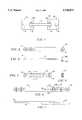
- FIG. 1shows a schematic drawing of the apparatus
- FIG. 2shows a plan view of the first assembly plate of an embodiment of the apparatus
- FIG. 3shows a side view of the first assembly plate of an embodiment of the apparatus
- FIG. 4shows a plan view of the second assembly plate of an embodiment of the apparatus
- FIG. 5shows a sectional view along the section line A--A of the second assembly plate of an embodiment of the apparatus
- FIG. 6shows a plan view of the embodiment of the apparatus which is composed of the first and second assembly plates.
- FIG. 7shows a side view of the assembled embodiment of the apparatus which is shown in FIG. 5.
- FIG. 1shows a first and a second assembly plate (10, 20), which are secured detachably on the bones by suitable first and second fixing means (11, 21), such as screws, for example.
- a connecting element (30)which is secured on a first and second connecting part (12, 22) makes it possible for the first and second assembly plates (10, 20) to move through a predetermined length in one plane.
- FIGS. 2 and 3show an embodiment of the apparatus.
- a first assembly plate (40)which has at least two first devices (41), is secured detachably in the manner known per se on the bone by suitable means, such as screws.
- at least one guide pin (60)is arranged at a predetermined spacing from at least two first devices (41). The guide pin (60) is used as the connecting element to the second assembly plate (50).
- FIG. 4shows a second assembly plate (50), which has at least two second devices (51), by means of which the second assembly plate (50) is firmly connected with the bone by suitable means, such as screws. Between two of the second devices (51), an aperture (52) is arranged, which comprises a longitudinally extending guide slot, which has in section a substantially T-shaped profile (see FIG. 4).
- FIGS. 6 and 7show the apparatus which is composed of the first and second assembly plate (40, 50).
- at least one guide pin (60)interacts with the guide slot 52 of the second assembly plate (50) in such a manner that displacement in the longitudinal direction 110 can be performed in one plane by a predetermined amount.
- rotation of the first assembly plate (40) against the second assembly plate (50)may also be desirable in the displacement plane.
- the first assembly plate (40)has only one guide pin (60), which is inserted to be displaceable in the T-shaped guide slot of the second assembly plate (50).
- rotation 120 of the assembly plates (40, 50) in relation to each otheris possible in the displacement plane around an axis (60a) of the guide pin (60).
- a further possible embodimentis a connecting element (30), which has a telescopic rod.
- the telescopic rodis attached via the first and second connecting parts (12, 22) on the assembly plates (10, 20) which are secured detachably on the bones by fixing means, such as screws.
- This telescopic rodpermits substantially linear movements of the first and second assembly plates (10, 20).
- all the components of the apparatusmust consist of physiologically compatible materials (such as, for example, precious metals, ceramics, plastics, gold-vitallium alloys, titanium, vanadium, high quality steels or alloys thereof etc.).
- physiologically compatible materialssuch as, for example, precious metals, ceramics, plastics, gold-vitallium alloys, titanium, vanadium, high quality steels or alloys thereof etc.
- the materialsmust be osseointegratable, so that the bone can grow undisturbed.
- the assembled apparatusis disposed at the sectioned point of the bone so that the first assembly plate 10 is secured on the first bone and the second assembly plate 20 is secured on the second bone by suitable means, such as screws, wherein the assembly plates 10, 20 are moved together as far as possible. Because of the tension developed within the connecting element (30), the assembly plates 10, 20 can be biased and therefore forces which oppose the bone can be adjusted or the assembly plates can be adjusted to lengthen the bone.
Landscapes
- Health & Medical Sciences (AREA)
- Life Sciences & Earth Sciences (AREA)
- Surgery (AREA)
- Animal Behavior & Ethology (AREA)
- General Health & Medical Sciences (AREA)
- Heart & Thoracic Surgery (AREA)
- Veterinary Medicine (AREA)
- Public Health (AREA)
- Epidemiology (AREA)
- Chemical & Material Sciences (AREA)
- Vascular Medicine (AREA)
- Orthopedic Medicine & Surgery (AREA)
- Engineering & Computer Science (AREA)
- Inorganic Chemistry (AREA)
- Ceramic Engineering (AREA)
- Neurology (AREA)
- Nuclear Medicine, Radiotherapy & Molecular Imaging (AREA)
- Biomedical Technology (AREA)
- Medical Informatics (AREA)
- Molecular Biology (AREA)
- Surgical Instruments (AREA)
Abstract
Description
This is a continuation of application Ser. No. 08/344,938 filed Nov. 23, 1994, now abandoned.
The invention concerns an apparatus for the mobile fixation of bones, in particular in the region of the face and skull or at the extremities of human or animal bodies, in order not to impede dynamic bone growth or desired movements of the bones after surgical operations, such as, for example, operations to correct retrusions of the midface region.
Conventional apparatus for the fixation of bones can be classified as either rigid fixations or variable fixations.
The invention is suitable, in particular, for craniofacial growth, such as in the case of small children who suffer from morbus apart or morbus crouzon or other cranial suture synostoses.
In the case of rigid fixations, plates are firmly connected to the bones by securing elements and thus they fix the position of the bones. The fixing plates are applied below the tissue directly on the bones, and, to the extent that this is necessary, are again removed after performing their function. However, there is the disadvantage in this case that the fixing plates prevent the drifting apart of the bones during growth. In particular for the correction of midfacial retrusion and cranial suture synostoses, however, room for manoeuvre is absolutely necessary, to allow the growth of the bone.
In the case of variable fixations, pins which project through the skin are secured on the bone. Because of an adjustable connecting rod which is arranged on the outside of the body between the pins, the spacing of the pins can be varied so that adaptation of the fixation to the growth process at the moment becomes possible. However, it is a disadvantage that due to the pins which project from the skin, there is a very high risk of infection. In particular, infections which occur on the human scalp after surgical operations may lead to situations which endanger life. In addition, when using such fixing apparatus, a very high degree of psychological stress is observed in the patients and their relatives.
It is the object of the present invention to fix the bones on the point of suture and, on the other hand, to allow the growth of the bones in a direction which is predetermined by the apparatus.
In accordance with the invention, the problem is solved by an apparatus for the mobile fixation of bones which has:
a first assembly plate, which can be fixed by suitable first fixing means on the bone and which has a first connecting part;
a second assembly plate, which can be fixed on the bone by suitable second fixing means and which has a second connecting part; and
optionally at least one further assembly plate, which can be fixed on the bone by suitable fixing means and which has a further connecting part which is mounted on a connecting element; and
the connecting element, which is mounted on the connecting parts so that the movement of the assembly plates to each other is substantially only possible in one plane and a change in the spacing of the assembly plates from one another is possible by a predetermined length.
Consequently, the apparatus for the mobile fixation of bones comprises two interconnected assembly plates, which are secured by suitable fixing means on the respective bone. The assembly plates are connected with each other by two connecting elements so that movement in one plane is possible without problems.
It is an advantage that the apparatus which is mounted directly on the bone by a surgical operation does not have any components which project outside the skin. Therefore, the risk of infection is clearly reduced. In addition, it is advantageous that because of the displaceability of the assembly plates in relation to each other, the drifting apart of the bone becomes possible, yet the bones can be simultaneously fixed and can remain stable.
All the components of the apparatus must consist of physiologically compatible materials (such as, for example, precious metals, ceramics, plastics, gold-vitallium alloys, titanium, vanadium, high quality steels, alloys thereof etc.), in order to prevent a defensive reaction of the human or animal body. At the same time, the materials must be osseointegratable, so that the bone can grow undisturbed.
In one embodiment, the two assembly plates are firmly connected with each other via a guide pin which is inserted displaceably in a guide slot. Thereby a movement in the longitudinal direction and a rotational movement around the axis of the guide pin are possible. The assembly plates are installed so that the first assembly plate is secured on one bone and the second assembly plate is inserted on the second bone by devices using suitable means, such as screws.
Furthermore, there is the possibility to move deliberately the assembly plates by the use of suitable tensioning devices having the connecting element (such as pressure springs, magnets etc.) so that the apparatus can not only be used to fix the bone fractures, but also for the distraction of bones.
Further objects, features and advantages of the invention will be described in more detail with reference to the drawings, by the following description of an embodiment of the apparatus.
FIG. 1 shows a schematic drawing of the apparatus;
FIG. 2 shows a plan view of the first assembly plate of an embodiment of the apparatus;
FIG. 3 shows a side view of the first assembly plate of an embodiment of the apparatus;
FIG. 4 shows a plan view of the second assembly plate of an embodiment of the apparatus;
FIG. 5 shows a sectional view along the section line A--A of the second assembly plate of an embodiment of the apparatus;
FIG. 6 shows a plan view of the embodiment of the apparatus which is composed of the first and second assembly plates; and
FIG. 7 shows a side view of the assembled embodiment of the apparatus which is shown in FIG. 5.
FIG. 1 shows a first and a second assembly plate (10, 20), which are secured detachably on the bones by suitable first and second fixing means (11, 21), such as screws, for example. A connecting element (30) which is secured on a first and second connecting part (12, 22) makes it possible for the first and second assembly plates (10, 20) to move through a predetermined length in one plane.
FIGS. 2 and 3 show an embodiment of the apparatus. Here a first assembly plate (40), which has at least two first devices (41), is secured detachably in the manner known per se on the bone by suitable means, such as screws. In addition, at least one guide pin (60) is arranged at a predetermined spacing from at least two first devices (41). The guide pin (60) is used as the connecting element to the second assembly plate (50).
FIG. 4 shows a second assembly plate (50), which has at least two second devices (51), by means of which the second assembly plate (50) is firmly connected with the bone by suitable means, such as screws. Between two of the second devices (51), an aperture (52) is arranged, which comprises a longitudinally extending guide slot, which has in section a substantially T-shaped profile (see FIG. 4).
FIGS. 6 and 7 show the apparatus which is composed of the first and second assembly plate (40, 50). Here at least one guide pin (60) interacts with theguide slot 52 of the second assembly plate (50) in such a manner that displacement in thelongitudinal direction 110 can be performed in one plane by a predetermined amount. Given certain requirements on the apparatus, rotation of the first assembly plate (40) against the second assembly plate (50) may also be desirable in the displacement plane. In the embodiment which is shown, the first assembly plate (40) has only one guide pin (60), which is inserted to be displaceable in the T-shaped guide slot of the second assembly plate (50). By using only one guide pin (60),rotation 120 of the assembly plates (40, 50) in relation to each other is possible in the displacement plane around an axis (60a) of the guide pin (60).
A further possible embodiment is a connecting element (30), which has a telescopic rod. The telescopic rod is attached via the first and second connecting parts (12, 22) on the assembly plates (10, 20) which are secured detachably on the bones by fixing means, such as screws. This telescopic rod permits substantially linear movements of the first and second assembly plates (10, 20). By faking use of at least one rotatable joint in the first or second connecting parts (12, 22) rotational movements within the movement plane are also possible.
To prevent defensive reactions of the human or animal body, all the components of the apparatus must consist of physiologically compatible materials (such as, for example, precious metals, ceramics, plastics, gold-vitallium alloys, titanium, vanadium, high quality steels or alloys thereof etc.). At the same time, the materials must be osseointegratable, so that the bone can grow undisturbed.
In the case of a surgical operation for example, as illustrated by FIG. 1, the assembled apparatus is disposed at the sectioned point of the bone so that thefirst assembly plate 10 is secured on the first bone and thesecond assembly plate 20 is secured on the second bone by suitable means, such as screws, wherein theassembly plates assembly plates
The invention was described to clarify it. Of course, the terminology which was used only serves for the specification and should by no means act restrictively.
Modifications and differences within the framework of the specification are possible, therefore the invention can be carried out in accordance with the protective scope which is specified by the claims, without corresponding to the wording of the specific description.
Claims (7)
1. A physiologically-compatible apparatus configured to passively but rigidly maintain at least a first bone or bone segment and a second bone or bone segment in a substantially coplanar relation, one to the other, while permitting substantially linear movement of said bones or bone segments along a bone growth axis, said apparatus comprising:
a first assembly plate which is configured to be fixed on said first bone or bone segment by a first fixing means and which has a first connecting part;
a second assembly plate which is configured to be fixed on said second bone or bone segment by a second fixing means and which has a second connecting part;
a connecting element located between said first and second assembly plates, said connecting element being mounted on said first and second connecting parts, said connecting element having a connecting element axis fixedly attached to said second connecting part of said second assembly plate said connecting element having one guide pin having a guide pin axis, said guide pin fixedly attached to said first connecting part of said first assembly plate, said guide pin slidably and rotatably attached to said connecting element axis,
so that said first and second assembly plates are configured to be initially moved together as far as possible along said connecting element axis when said first and said second fixing means are fixed on said first and second bones or bone segments,
wherein movement of said first and second assembly plates in relation to each other is substantially possible linearly between said guide pin attached to said first connecting part of said first assembly plate along said connecting element axis attached to said second connecting part of said second assembly plate, and rotationally around said guide pin axis of said guide pin,
wherein said first and second assembly plates are configured to move freely from each other substantially along said connecting element axis in response to bone growth along said bone growth axis, and wherein said first and second assembly plates and said connecting element are configured to maintain said substantially coplanar relation between said first and second bones or bone segments.
2. An apparatus for the mobile fixation of bones in accordance with claim 1, wherein:
said first fixing means has at least two devices which can be fixed on said first bone or bone segment;
said second fixing means has at least two second devices which can be fixed on said first bone or bone segment;
said first connecting part has means for mounting said connecting element on said first assembly plate; and
said second connecting part has means for mounting said connecting element on said second assembly plate.
3. An apparatus for the mobile fixation of bones in accordance with claim 1, wherein said means for fixing said first and second assembly plates on said bones have screws.
4. An apparatus for the mobile fixation of bones in accordance with claim 1, wherein said second connecting part has an aperture formed along said connecting element axis, therein to which one end of said guide pin is displaceably mounted.
5. An apparatus for the mobile fixation of bones in accordance with claim 1, wherein:
said second connecting part comprises a guide slot said connecting element axis, in which a cross-section of said guide is substantially T-shaped; and
wherein said guide pin is slidably and rotatably displaced within said T-shaped guide slot.
6. An apparatus for the mobile fixation of bones in accordance with claim 1, wherein the material for the apparatus is composed of osseo-integratable materials.
7. An apparatus for the mobile fixation of bones in accordance with claim 6, wherein the materials for the apparatus are selected from a group which comprises physiologically compatible materials, precious metals, ceramics, plastics, gold-vitallium alloys, titanium, vanadium, high quality steels as well as alloys thereof.
Priority Applications (1)
| Application Number | Priority Date | Filing Date | Title |
|---|---|---|---|
| US08/683,620US5749873A (en) | 1993-11-26 | 1996-07-17 | Apparatus for the mobile fixation of bones |
Applications Claiming Priority (4)
| Application Number | Priority Date | Filing Date | Title |
|---|---|---|---|
| DE4340398.0 | 1993-11-26 | ||
| DE4340398ADE4340398C2 (en) | 1993-11-26 | 1993-11-26 | Device for the passive connection of two bones in one plane, movable in one plane |
| US34493894A | 1994-11-23 | 1994-11-23 | |
| US08/683,620US5749873A (en) | 1993-11-26 | 1996-07-17 | Apparatus for the mobile fixation of bones |
Related Parent Applications (1)
| Application Number | Title | Priority Date | Filing Date |
|---|---|---|---|
| US34493894AContinuation | 1993-11-26 | 1994-11-23 |
Publications (1)
| Publication Number | Publication Date |
|---|---|
| US5749873Atrue US5749873A (en) | 1998-05-12 |
Family
ID=6503562
Family Applications (1)
| Application Number | Title | Priority Date | Filing Date |
|---|---|---|---|
| US08/683,620Expired - Fee RelatedUS5749873A (en) | 1993-11-26 | 1996-07-17 | Apparatus for the mobile fixation of bones |
Country Status (2)
| Country | Link |
|---|---|
| US (1) | US5749873A (en) |
| DE (1) | DE4340398C2 (en) |
Cited By (41)
| Publication number | Priority date | Publication date | Assignee | Title |
|---|---|---|---|---|
| US20030204259A1 (en)* | 2000-12-13 | 2003-10-30 | Goble E. Marlowe | Multiple facet joint replacement |
| US20040204710A1 (en)* | 2003-04-09 | 2004-10-14 | Tushar Patel | Drill guide and plate inserter |
| US20040204717A1 (en)* | 2003-04-09 | 2004-10-14 | Jonathan Fanger | Guide for spinal tools, implants, and devices |
| US20050059970A1 (en)* | 2003-09-17 | 2005-03-17 | Eric Kolb | Bone fixation systems |
| US6872210B2 (en) | 2001-02-23 | 2005-03-29 | James P. Hearn | Sternum fixation device |
| US20050234551A1 (en)* | 2001-03-02 | 2005-10-20 | Facet Solutions, Inc. | Method and apparatus for spine joint replacement |
| US20050277941A1 (en)* | 2004-05-27 | 2005-12-15 | Trumble Thomas E | Method and device for use in osteotomy |
| US7041136B2 (en) | 2000-11-29 | 2006-05-09 | Facet Solutions, Inc. | Facet joint replacement |
| US7090676B2 (en) | 2002-11-19 | 2006-08-15 | Acumed Llc | Adjustable bone plates |
| US20060189983A1 (en)* | 2005-02-22 | 2006-08-24 | Medicinelodge, Inc. | Apparatus and method for dynamic vertebral stabilization |
| US20060217728A1 (en)* | 2005-03-28 | 2006-09-28 | Alan Chervitz | Polyaxial reaming apparatus and method |
| US20060217718A1 (en)* | 2005-03-28 | 2006-09-28 | Facet Solutions, Inc. | Facet joint implant crosslinking apparatus and method |
| US7153309B2 (en) | 2002-11-19 | 2006-12-26 | Acumed Llc | Guide system for bone-repair devices |
| US7189237B2 (en) | 2002-11-19 | 2007-03-13 | Acumed Llc | Deformable bone plates |
| US20080039847A1 (en)* | 2006-08-09 | 2008-02-14 | Mark Piper | Implant and system for stabilization of the spine |
| US20080161861A1 (en)* | 2006-10-17 | 2008-07-03 | Acumed Llc | Bone fixation with a strut-stabilized bone plate |
| US7507242B2 (en) | 2004-06-02 | 2009-03-24 | Facet Solutions | Surgical measurement and resection framework |
| US20090088802A1 (en)* | 2000-12-13 | 2009-04-02 | Facet Solutions, Inc. | Prosthesis for the replacement of a posterior element of a vertebra |
| US7537604B2 (en) | 2002-11-19 | 2009-05-26 | Acumed Llc | Bone plates with slots |
| US7537596B2 (en) | 2003-06-20 | 2009-05-26 | Acumed Llc | Bone plates with intraoperatively tapped apertures |
| US7537603B2 (en) | 2002-07-22 | 2009-05-26 | Acumed Llc | Bone fusion system |
| US7578825B2 (en) | 2004-04-19 | 2009-08-25 | Acumed Llc | Placement of fasteners into bone |
| US7588590B2 (en) | 2003-12-10 | 2009-09-15 | Facet Solutions, Inc | Spinal facet implant with spherical implant apposition surface and bone bed and methods of use |
| US7635365B2 (en) | 2003-08-28 | 2009-12-22 | Ellis Thomas J | Bone plates |
| US7717945B2 (en) | 2002-07-22 | 2010-05-18 | Acumed Llc | Orthopedic systems |
| US7722647B1 (en) | 2005-03-14 | 2010-05-25 | Facet Solutions, Inc. | Apparatus and method for posterior vertebral stabilization |
| US7909829B2 (en) | 2003-06-27 | 2011-03-22 | Depuy Spine, Inc. | Tissue retractor and drill guide |
| US7909848B2 (en) | 2003-06-27 | 2011-03-22 | Depuy Spine, Inc. | Tissue retractor and guide device |
| US7935123B2 (en) | 2003-04-09 | 2011-05-03 | Depuy Acromed, Inc. | Drill guide with alignment feature |
| US7993373B2 (en) | 2005-02-22 | 2011-08-09 | Hoy Robert W | Polyaxial orthopedic fastening apparatus |
| US8109973B2 (en) | 2005-10-31 | 2012-02-07 | Stryker Spine | Method for dynamic vertebral stabilization |
| US8177819B2 (en) | 2004-04-22 | 2012-05-15 | Acumed Llc | Expanded fixation of bones |
| US8206418B2 (en) | 2007-01-10 | 2012-06-26 | Gmedelaware 2 Llc | System and method for facet joint replacement with detachable coupler |
| US8556936B2 (en) | 2000-11-29 | 2013-10-15 | Gmedelaware 2 Llc | Facet joint replacement |
| US8562649B2 (en) | 2004-02-17 | 2013-10-22 | Gmedelaware 2 Llc | System and method for multiple level facet joint arthroplasty and fusion |
| US8568417B2 (en) | 2009-12-18 | 2013-10-29 | Charles River Engineering Solutions And Technologies, Llc | Articulating tool and methods of using |
| US8900273B2 (en) | 2005-02-22 | 2014-12-02 | Gmedelaware 2 Llc | Taper-locking fixation system |
| US9237910B2 (en) | 2012-01-26 | 2016-01-19 | Acute Innovations Llc | Clip for rib stabilization |
| US9775657B2 (en) | 2011-09-30 | 2017-10-03 | Acute Innovations Llc | Bone fixation system with opposed mounting portions |
| US9956015B2 (en) | 2014-07-03 | 2018-05-01 | Acumed Llc | Bone plate with movable joint |
| US12285197B2 (en) | 2008-10-10 | 2025-04-29 | Acumed Llc | Bone fixation system with opposed mounting portions |
Families Citing this family (1)
| Publication number | Priority date | Publication date | Assignee | Title |
|---|---|---|---|---|
| EP1205154A3 (en)* | 2000-11-08 | 2003-04-02 | Aesculap AG & Co. KG | Osteosynthesis plating apparatus and method with extension plate |
Citations (26)
| Publication number | Priority date | Publication date | Assignee | Title |
|---|---|---|---|---|
| SU335797A1 (en)* | ACTIVE START OF HERBICID MEANS | |||
| DE156570C (en)* | ||||
| US2406832A (en)* | 1945-03-05 | 1946-09-03 | Mervyn G Hardinge | Fracture plate |
| US2486303A (en)* | 1948-04-29 | 1949-10-25 | Harry Herschel Leiter | Surgical appliance for bone fractures |
| DE867422C (en)* | 1951-11-13 | 1953-02-16 | Alfred Dr Med Abel | Screw-on bone plate for the healing of broken bones |
| FR1051847A (en)* | 1952-02-28 | 1954-01-19 | Adjustable splint for osteosynthesis, allowing the impaction of fragments | |
| US3547114A (en)* | 1967-07-07 | 1970-12-15 | Edward J Haboush | Compensating plate means for bone fractures |
| SU491382A1 (en)* | 1973-06-21 | 1975-11-15 | Центральный Ордена Трудового Красного Знамени Научно-Исследовательский Институт Травматологии И Ортопедии Им. Н.Н.Приорова | Device for compression osteosynthesis of the intertrochanter area of the thigh |
| DE2621175A1 (en)* | 1976-05-11 | 1977-11-17 | Westerhoff Erhard | Implanted mechanism for lengthening limb - has telescopic members secured to bone sections by screws and held apart by gradually advanced ratchet |
| US4085744A (en)* | 1977-01-31 | 1978-04-25 | David Warren Lewis | Spinal column prostheses orthoses |
| US4096857A (en)* | 1976-01-20 | 1978-06-27 | Messerschmitt-Boelkow-Blohm Gmbh | Telescopically adjustable surgical instrument |
| SU829103A1 (en)* | 1975-06-13 | 1981-05-15 | Shevts Boris D | Pressure gradient detector |
| SU915840A1 (en)* | 1980-05-07 | 1982-03-30 | Ildus Z Vafin | Device for osteosynthesis |
| SU1082420A1 (en)* | 1982-06-11 | 1984-03-30 | Центральный научно-исследовательский институт травматологии и ортопедии им.Н.Н.Приорова | Compression device for osteosynthesis |
| US4611582A (en)* | 1983-12-27 | 1986-09-16 | Wisconsin Alumni Research Foundation | Vertebral clamp |
| DE3722595A1 (en)* | 1987-07-08 | 1989-01-19 | Robert Sturtzkopf | Device for the external fixation of bone fragments |
| EP0346269A2 (en)* | 1988-06-06 | 1989-12-13 | Gerhard Dr. Fuhrmann | Intervertebral disk endoprothesis |
| DE3819840A1 (en)* | 1988-06-10 | 1989-12-14 | Link Waldemar Gmbh Co | Surgical clip, especially microclip |
| SU1648419A1 (en)* | 1988-12-27 | 1991-05-15 | Пермский государственный медицинский институт | Device for fixing fractured bone fragments |
| SU1683723A1 (en)* | 1989-03-01 | 1991-10-15 | Запорожский Областной Отдел Здравоохранения | Device for osteosynthesis |
| US5092889A (en)* | 1989-04-14 | 1992-03-03 | Campbell Robert M Jr | Expandable vertical prosthetic rib |
| US5129903A (en)* | 1988-06-18 | 1992-07-14 | Luhr Hans Georg | Bone plate |
| SU1754085A1 (en)* | 1989-01-24 | 1992-08-15 | Kadyrov Zhannat N | Plate for bony fragment compression |
| US5375823A (en)* | 1992-06-25 | 1994-12-27 | Societe Psi | Application of an improved damper to an intervertebral stabilization device |
| US5405391A (en)* | 1993-02-16 | 1995-04-11 | Hednerson; Fraser C. | Fusion stabilization chamber |
| US5466261A (en)* | 1992-11-19 | 1995-11-14 | Wright Medical Technology, Inc. | Non-invasive expandable prosthesis for growing children |
Family Cites Families (1)
| Publication number | Priority date | Publication date | Assignee | Title |
|---|---|---|---|---|
| DE3121271A1 (en)* | 1981-05-29 | 1982-12-23 | Max Bernhard 7900 Ulm Ulrich | DISTRACTION DEVICE FOR CORRECTION, IN PARTICULAR KYPHOTIC SPINE AREAS |
- 1993
- 1993-11-26DEDE4340398Apatent/DE4340398C2/ennot_activeExpired - Fee Related
- 1996
- 1996-07-17USUS08/683,620patent/US5749873A/ennot_activeExpired - Fee Related
Patent Citations (26)
| Publication number | Priority date | Publication date | Assignee | Title |
|---|---|---|---|---|
| SU335797A1 (en)* | ACTIVE START OF HERBICID MEANS | |||
| DE156570C (en)* | ||||
| US2406832A (en)* | 1945-03-05 | 1946-09-03 | Mervyn G Hardinge | Fracture plate |
| US2486303A (en)* | 1948-04-29 | 1949-10-25 | Harry Herschel Leiter | Surgical appliance for bone fractures |
| DE867422C (en)* | 1951-11-13 | 1953-02-16 | Alfred Dr Med Abel | Screw-on bone plate for the healing of broken bones |
| FR1051847A (en)* | 1952-02-28 | 1954-01-19 | Adjustable splint for osteosynthesis, allowing the impaction of fragments | |
| US3547114A (en)* | 1967-07-07 | 1970-12-15 | Edward J Haboush | Compensating plate means for bone fractures |
| SU491382A1 (en)* | 1973-06-21 | 1975-11-15 | Центральный Ордена Трудового Красного Знамени Научно-Исследовательский Институт Травматологии И Ортопедии Им. Н.Н.Приорова | Device for compression osteosynthesis of the intertrochanter area of the thigh |
| SU829103A1 (en)* | 1975-06-13 | 1981-05-15 | Shevts Boris D | Pressure gradient detector |
| US4096857A (en)* | 1976-01-20 | 1978-06-27 | Messerschmitt-Boelkow-Blohm Gmbh | Telescopically adjustable surgical instrument |
| DE2621175A1 (en)* | 1976-05-11 | 1977-11-17 | Westerhoff Erhard | Implanted mechanism for lengthening limb - has telescopic members secured to bone sections by screws and held apart by gradually advanced ratchet |
| US4085744A (en)* | 1977-01-31 | 1978-04-25 | David Warren Lewis | Spinal column prostheses orthoses |
| SU915840A1 (en)* | 1980-05-07 | 1982-03-30 | Ildus Z Vafin | Device for osteosynthesis |
| SU1082420A1 (en)* | 1982-06-11 | 1984-03-30 | Центральный научно-исследовательский институт травматологии и ортопедии им.Н.Н.Приорова | Compression device for osteosynthesis |
| US4611582A (en)* | 1983-12-27 | 1986-09-16 | Wisconsin Alumni Research Foundation | Vertebral clamp |
| DE3722595A1 (en)* | 1987-07-08 | 1989-01-19 | Robert Sturtzkopf | Device for the external fixation of bone fragments |
| EP0346269A2 (en)* | 1988-06-06 | 1989-12-13 | Gerhard Dr. Fuhrmann | Intervertebral disk endoprothesis |
| DE3819840A1 (en)* | 1988-06-10 | 1989-12-14 | Link Waldemar Gmbh Co | Surgical clip, especially microclip |
| US5129903A (en)* | 1988-06-18 | 1992-07-14 | Luhr Hans Georg | Bone plate |
| SU1648419A1 (en)* | 1988-12-27 | 1991-05-15 | Пермский государственный медицинский институт | Device for fixing fractured bone fragments |
| SU1754085A1 (en)* | 1989-01-24 | 1992-08-15 | Kadyrov Zhannat N | Plate for bony fragment compression |
| SU1683723A1 (en)* | 1989-03-01 | 1991-10-15 | Запорожский Областной Отдел Здравоохранения | Device for osteosynthesis |
| US5092889A (en)* | 1989-04-14 | 1992-03-03 | Campbell Robert M Jr | Expandable vertical prosthetic rib |
| US5375823A (en)* | 1992-06-25 | 1994-12-27 | Societe Psi | Application of an improved damper to an intervertebral stabilization device |
| US5466261A (en)* | 1992-11-19 | 1995-11-14 | Wright Medical Technology, Inc. | Non-invasive expandable prosthesis for growing children |
| US5405391A (en)* | 1993-02-16 | 1995-04-11 | Hednerson; Fraser C. | Fusion stabilization chamber |
Cited By (110)
| Publication number | Priority date | Publication date | Assignee | Title |
|---|---|---|---|---|
| US8556936B2 (en) | 2000-11-29 | 2013-10-15 | Gmedelaware 2 Llc | Facet joint replacement |
| US7618453B2 (en) | 2000-11-29 | 2009-11-17 | Facet Solutions, Inc | Facet joint replacement |
| US8313511B2 (en) | 2000-11-29 | 2012-11-20 | Gmedelaware 2 Llc | Facet joint replacement |
| US7621955B2 (en) | 2000-11-29 | 2009-11-24 | Facet Solutions, Inc. | Facet joint replacement |
| US7041136B2 (en) | 2000-11-29 | 2006-05-09 | Facet Solutions, Inc. | Facet joint replacement |
| US7618455B2 (en) | 2000-12-13 | 2009-11-17 | Facet Solutions, Inc | Multiple facet joint replacement |
| US20090088802A1 (en)* | 2000-12-13 | 2009-04-02 | Facet Solutions, Inc. | Prosthesis for the replacement of a posterior element of a vertebra |
| US8066741B2 (en) | 2000-12-13 | 2011-11-29 | Gmedelaware 2 Llc | Prosthesis for the replacement of a posterior element of a vertebra |
| US20030204259A1 (en)* | 2000-12-13 | 2003-10-30 | Goble E. Marlowe | Multiple facet joint replacement |
| US7074237B2 (en) | 2000-12-13 | 2006-07-11 | Facet Solutions, Inc. | Multiple facet joint replacement |
| US8876824B2 (en) | 2001-02-23 | 2014-11-04 | DePuy Synthes Products, LLC | Sternum fixation device |
| US20050124996A1 (en)* | 2001-02-23 | 2005-06-09 | Hearn James P. | Sternum fixation device |
| US6872210B2 (en) | 2001-02-23 | 2005-03-29 | James P. Hearn | Sternum fixation device |
| US8221421B2 (en) | 2001-02-23 | 2012-07-17 | Synthes Usa, Llc | Sternum fixation device |
| US7566345B1 (en) | 2001-03-01 | 2009-07-28 | Facet Solutions, Inc | Prosthesis for the replacement of a posterior element of a vertebra |
| US7955390B2 (en) | 2001-03-02 | 2011-06-07 | GME Delaware 2 LLC | Method and apparatus for spine joint replacement |
| US7445635B2 (en) | 2001-03-02 | 2008-11-04 | Facet Solutions | Method and apparatus for spine joint replacement |
| US7090698B2 (en) | 2001-03-02 | 2006-08-15 | Facet Solutions | Method and apparatus for spine joint replacement |
| US20050234551A1 (en)* | 2001-03-02 | 2005-10-20 | Facet Solutions, Inc. | Method and apparatus for spine joint replacement |
| US8425574B2 (en) | 2002-07-22 | 2013-04-23 | Acumed, Llc | Bone fixation with a bone plate attached to a fastener assembly |
| US7537603B2 (en) | 2002-07-22 | 2009-05-26 | Acumed Llc | Bone fusion system |
| US9308033B2 (en) | 2002-07-22 | 2016-04-12 | Acumed Llc | Adjustable bone plates |
| US10456180B2 (en) | 2002-07-22 | 2019-10-29 | Acumed Llc | Adjustable bone plates |
| US7717945B2 (en) | 2002-07-22 | 2010-05-18 | Acumed Llc | Orthopedic systems |
| US7326212B2 (en) | 2002-11-19 | 2008-02-05 | Acumed Llc | Bone plates with reference marks |
| US7153309B2 (en) | 2002-11-19 | 2006-12-26 | Acumed Llc | Guide system for bone-repair devices |
| US7704251B2 (en) | 2002-11-19 | 2010-04-27 | Acumed Llc | Adjustable bone plates |
| US7537604B2 (en) | 2002-11-19 | 2009-05-26 | Acumed Llc | Bone plates with slots |
| US7090676B2 (en) | 2002-11-19 | 2006-08-15 | Acumed Llc | Adjustable bone plates |
| US7189237B2 (en) | 2002-11-19 | 2007-03-13 | Acumed Llc | Deformable bone plates |
| US8394107B2 (en) | 2003-04-09 | 2013-03-12 | Depuy Spine, Inc. | Guide for spinal tools, implants, and devices |
| US7416553B2 (en) | 2003-04-09 | 2008-08-26 | Depuy Acromed, Inc. | Drill guide and plate inserter |
| US20110015685A1 (en)* | 2003-04-09 | 2011-01-20 | Depuy Spine, Inc. | Guide for spinal tools, implants, and devices |
| US7776047B2 (en) | 2003-04-09 | 2010-08-17 | Depuy Spine, Inc. | Guide for spinal tools, implants, and devices |
| US7935123B2 (en) | 2003-04-09 | 2011-05-03 | Depuy Acromed, Inc. | Drill guide with alignment feature |
| US20040204717A1 (en)* | 2003-04-09 | 2004-10-14 | Jonathan Fanger | Guide for spinal tools, implants, and devices |
| US20040204710A1 (en)* | 2003-04-09 | 2004-10-14 | Tushar Patel | Drill guide and plate inserter |
| US7537596B2 (en) | 2003-06-20 | 2009-05-26 | Acumed Llc | Bone plates with intraoperatively tapped apertures |
| US7909848B2 (en) | 2003-06-27 | 2011-03-22 | Depuy Spine, Inc. | Tissue retractor and guide device |
| US7909829B2 (en) | 2003-06-27 | 2011-03-22 | Depuy Spine, Inc. | Tissue retractor and drill guide |
| US7635365B2 (en) | 2003-08-28 | 2009-12-22 | Ellis Thomas J | Bone plates |
| US8632573B2 (en) | 2003-08-28 | 2014-01-21 | Thomas J. Ellis | Bone fixation system |
| US7695501B2 (en) | 2003-08-28 | 2010-04-13 | Ellis Thomas J | Bone fixation system |
| US20050059970A1 (en)* | 2003-09-17 | 2005-03-17 | Eric Kolb | Bone fixation systems |
| US7588590B2 (en) | 2003-12-10 | 2009-09-15 | Facet Solutions, Inc | Spinal facet implant with spherical implant apposition surface and bone bed and methods of use |
| US7753937B2 (en) | 2003-12-10 | 2010-07-13 | Facet Solutions Inc. | Linked bilateral spinal facet implants and methods of use |
| US8419770B2 (en) | 2003-12-10 | 2013-04-16 | Gmedelaware 2 Llc | Spinal facet implants with mating articulating bearing surface and methods of use |
| US8926700B2 (en) | 2003-12-10 | 2015-01-06 | Gmedelware 2 LLC | Spinal facet joint implant |
| US8579941B2 (en) | 2004-02-17 | 2013-11-12 | Alan Chervitz | Linked bilateral spinal facet implants and methods of use |
| US8906063B2 (en) | 2004-02-17 | 2014-12-09 | Gmedelaware 2 Llc | Spinal facet joint implant |
| US8562649B2 (en) | 2004-02-17 | 2013-10-22 | Gmedelaware 2 Llc | System and method for multiple level facet joint arthroplasty and fusion |
| US7998177B2 (en) | 2004-02-17 | 2011-08-16 | Gmedelaware 2 Llc | Linked bilateral spinal facet implants and methods of use |
| US7998178B2 (en) | 2004-02-17 | 2011-08-16 | Gmedelaware 2 Llc | Linked bilateral spinal facet implants and methods of use |
| US7914560B2 (en) | 2004-02-17 | 2011-03-29 | Gmedelaware 2 Llc | Spinal facet implant with spherical implant apposition surface and bone bed and methods of use |
| US7578825B2 (en) | 2004-04-19 | 2009-08-25 | Acumed Llc | Placement of fasteners into bone |
| US8177819B2 (en) | 2004-04-22 | 2012-05-15 | Acumed Llc | Expanded fixation of bones |
| US20050277941A1 (en)* | 2004-05-27 | 2005-12-15 | Trumble Thomas E | Method and device for use in osteotomy |
| US7540874B2 (en)* | 2004-05-27 | 2009-06-02 | Trimed Inc. | Method and device for use in osteotomy |
| US7507242B2 (en) | 2004-06-02 | 2009-03-24 | Facet Solutions | Surgical measurement and resection framework |
| US7815648B2 (en) | 2004-06-02 | 2010-10-19 | Facet Solutions, Inc | Surgical measurement systems and methods |
| US7588578B2 (en) | 2004-06-02 | 2009-09-15 | Facet Solutions, Inc | Surgical measurement systems and methods |
| US8777994B2 (en) | 2004-06-02 | 2014-07-15 | Gmedelaware 2 Llc | System and method for multiple level facet joint arthroplasty and fusion |
| US20090099607A1 (en)* | 2005-02-22 | 2009-04-16 | Stryker Spine | Apparatus and method for dynamic vertebral stabilization |
| US8974499B2 (en) | 2005-02-22 | 2015-03-10 | Stryker Spine | Apparatus and method for dynamic vertebral stabilization |
| US20100042153A1 (en)* | 2005-02-22 | 2010-02-18 | Fallin T Wade | Apparatus And Method For Dynamic Vertebral Stabilization |
| US9486244B2 (en) | 2005-02-22 | 2016-11-08 | Stryker European Holdings I, Llc | Apparatus and method for dynamic vertebral stabilization |
| US9949762B2 (en) | 2005-02-22 | 2018-04-24 | Stryker European Holdings I, Llc | Apparatus and method for dynamic vertebral stabilization |
| US7361196B2 (en) | 2005-02-22 | 2008-04-22 | Stryker Spine | Apparatus and method for dynamic vertebral stabilization |
| US8226687B2 (en) | 2005-02-22 | 2012-07-24 | Stryker Spine | Apparatus and method for dynamic vertebral stabilization |
| US20060189984A1 (en)* | 2005-02-22 | 2006-08-24 | Medicinelodge, Inc. | Apparatus and method for dynamic vertebral stabilization |
| US7604654B2 (en) | 2005-02-22 | 2009-10-20 | Stryker Spine | Apparatus and method for dynamic vertebral stabilization |
| US8062336B2 (en) | 2005-02-22 | 2011-11-22 | Gmedelaware 2 Llc | Polyaxial orthopedic fastening apparatus with independent locking modes |
| US8900273B2 (en) | 2005-02-22 | 2014-12-02 | Gmedelaware 2 Llc | Taper-locking fixation system |
| US20060189983A1 (en)* | 2005-02-22 | 2006-08-24 | Medicinelodge, Inc. | Apparatus and method for dynamic vertebral stabilization |
| US7625393B2 (en) | 2005-02-22 | 2009-12-01 | Stryker Spine | Apparatus and method for dynamic vertebral stabilization |
| US7993373B2 (en) | 2005-02-22 | 2011-08-09 | Hoy Robert W | Polyaxial orthopedic fastening apparatus |
| US20100010544A1 (en)* | 2005-02-22 | 2010-01-14 | Stryker Spine | Apparatus and method for dynamic vertebral stabilization |
| US7722647B1 (en) | 2005-03-14 | 2010-05-25 | Facet Solutions, Inc. | Apparatus and method for posterior vertebral stabilization |
| US7758581B2 (en) | 2005-03-28 | 2010-07-20 | Facet Solutions, Inc. | Polyaxial reaming apparatus and method |
| US20060217718A1 (en)* | 2005-03-28 | 2006-09-28 | Facet Solutions, Inc. | Facet joint implant crosslinking apparatus and method |
| US20060217728A1 (en)* | 2005-03-28 | 2006-09-28 | Alan Chervitz | Polyaxial reaming apparatus and method |
| US8764801B2 (en) | 2005-03-28 | 2014-07-01 | Gmedelaware 2 Llc | Facet joint implant crosslinking apparatus and method |
| US9445846B2 (en) | 2005-10-31 | 2016-09-20 | Stryker European Holdings I, Llc | System and method for dynamic vertebral stabilization |
| US8137385B2 (en) | 2005-10-31 | 2012-03-20 | Stryker Spine | System and method for dynamic vertebral stabilization |
| US10004539B2 (en) | 2005-10-31 | 2018-06-26 | Stryker European Holdings I, Llc | System and method for dynamic vertebral stabilization |
| US8623059B2 (en) | 2005-10-31 | 2014-01-07 | Stryker Spine | System and method for dynamic vertebral stabilization |
| US8529603B2 (en) | 2005-10-31 | 2013-09-10 | Stryker Spine | System and method for dynamic vertebral stabilization |
| US8109973B2 (en) | 2005-10-31 | 2012-02-07 | Stryker Spine | Method for dynamic vertebral stabilization |
| US20080039847A1 (en)* | 2006-08-09 | 2008-02-14 | Mark Piper | Implant and system for stabilization of the spine |
| US20080161861A1 (en)* | 2006-10-17 | 2008-07-03 | Acumed Llc | Bone fixation with a strut-stabilized bone plate |
| US8231662B2 (en) | 2006-10-17 | 2012-07-31 | Acumed Llc | Bone fixation with a strut-stabilized bone plate |
| US8308768B2 (en) | 2007-01-10 | 2012-11-13 | Gmedelaware 2 Llc | System and method for facet joint replacement |
| US8252027B2 (en) | 2007-01-10 | 2012-08-28 | Gmedelaware 2 Llc | System and method for facet joint replacement |
| US8211147B2 (en) | 2007-01-10 | 2012-07-03 | Gmedelaware 2 Llc | System and method for facet joint replacement |
| US8206418B2 (en) | 2007-01-10 | 2012-06-26 | Gmedelaware 2 Llc | System and method for facet joint replacement with detachable coupler |
| US8333789B2 (en) | 2007-01-10 | 2012-12-18 | Gmedelaware 2 Llc | Facet joint replacement |
| US8353933B2 (en) | 2007-04-17 | 2013-01-15 | Gmedelaware 2 Llc | Facet joint replacement |
| US8702759B2 (en) | 2007-04-17 | 2014-04-22 | Gmedelaware 2 Llc | System and method for bone anchorage |
| US9050144B2 (en) | 2007-04-17 | 2015-06-09 | Gmedelaware 2 Llc | System and method for implant anchorage with anti-rotation features |
| US12285197B2 (en) | 2008-10-10 | 2025-04-29 | Acumed Llc | Bone fixation system with opposed mounting portions |
| US9808297B2 (en) | 2008-10-10 | 2017-11-07 | Acute Innovations Llc | Bone fixation system with opposed mounting portions |
| US11911083B2 (en) | 2008-10-10 | 2024-02-27 | Acumed Llc | Bone fixation system with opposed mounting portions |
| US11083504B2 (en) | 2008-10-10 | 2021-08-10 | Acumed Llc | Bone fixation system with opposed mounting portions |
| US9924986B2 (en) | 2009-12-18 | 2018-03-27 | Charles River Engineering Solutions And Technologies, Llc | Articulating tool and methods of using |
| US8568417B2 (en) | 2009-12-18 | 2013-10-29 | Charles River Engineering Solutions And Technologies, Llc | Articulating tool and methods of using |
| US11033306B2 (en) | 2009-12-18 | 2021-06-15 | Charles River Engineering Solutions And Technologies, Llc | Articulating tool and methods of using |
| US9775657B2 (en) | 2011-09-30 | 2017-10-03 | Acute Innovations Llc | Bone fixation system with opposed mounting portions |
| US9237910B2 (en) | 2012-01-26 | 2016-01-19 | Acute Innovations Llc | Clip for rib stabilization |
| US10159515B2 (en) | 2014-07-03 | 2018-12-25 | Acumed Llc | Bone plate with movable joint |
| US9956015B2 (en) | 2014-07-03 | 2018-05-01 | Acumed Llc | Bone plate with movable joint |
Also Published As
| Publication number | Publication date |
|---|---|
| DE4340398C2 (en) | 1997-06-19 |
| DE4340398A1 (en) | 1995-06-01 |
Similar Documents
| Publication | Publication Date | Title |
|---|---|---|
| US5749873A (en) | Apparatus for the mobile fixation of bones | |
| US5358504A (en) | Fixation brace with focal hinge | |
| US4895141A (en) | Unilateral external fixation device | |
| US6171309B1 (en) | External fixator for repairing fractures of distal radius and wrist | |
| US6162224A (en) | External fixator for repairing fractures of distal radius and wrist | |
| US6245071B1 (en) | External fixation device for bone | |
| US7291148B2 (en) | External fixator for Colles' fracture | |
| US5545162A (en) | External fixator for repairing fractures of distal radius and wrist | |
| US4988349A (en) | Device for osteosynthesis | |
| KR920010760B1 (en) | Dynamic external fixation device for the wrist | |
| US5976134A (en) | External fixator for repairing fractures | |
| JP4598760B2 (en) | ADJUSTING ROD AND CONNECTOR DEVICE, AND ITS USING METHOD | |
| EP2672908B1 (en) | External orthopaedic fixator for the elbow joint | |
| US4747400A (en) | External fixation device | |
| DE8614898U1 (en) | Dynamic external fixation for bone | |
| SK33994A3 (en) | External axial fixator for osteosynthesis | |
| JPH01121046A (en) | Apparatus for maintaining relative position of spinal cord in spine | |
| CZ288765B6 (en) | Apparatus for correction of spine deformities | |
| EP1439787B1 (en) | A system for fixation of fractures comprising an elastic chassis | |
| US20090222006A1 (en) | External fixator | |
| EP3968879B1 (en) | Medical transverse connector having a floating bearing | |
| US20080221572A1 (en) | Device for temporary fixation of parts of a human joint | |
| US6224594B1 (en) | Devices for passive motion of joints under traction | |
| EP3628250B1 (en) | Medical positioning device | |
| SU1353432A1 (en) | Arrangement for fixing head |
Legal Events
| Date | Code | Title | Description |
|---|---|---|---|
| REMI | Maintenance fee reminder mailed | ||
| LAPS | Lapse for failure to pay maintenance fees | ||
| STCH | Information on status: patent discontinuation | Free format text:PATENT EXPIRED DUE TO NONPAYMENT OF MAINTENANCE FEES UNDER 37 CFR 1.362 | |
| FP | Expired due to failure to pay maintenance fee | Effective date:20020512 |