US5749872A - Keyed/keyless barrel for bone plates - Google Patents
Keyed/keyless barrel for bone platesDownload PDFInfo
- Publication number
- US5749872A US5749872AUS08/525,853US52585395AUS5749872AUS 5749872 AUS5749872 AUS 5749872AUS 52585395 AUS52585395 AUS 52585395AUS 5749872 AUS5749872 AUS 5749872A
- Authority
- US
- United States
- Prior art keywords
- barrel
- lag screw
- fixator
- end portion
- keyed
- Prior art date
- Legal status (The legal status is an assumption and is not a legal conclusion. Google has not performed a legal analysis and makes no representation as to the accuracy of the status listed.)
- Expired - Lifetime
Links
Images


Classifications
- A—HUMAN NECESSITIES
- A61—MEDICAL OR VETERINARY SCIENCE; HYGIENE
- A61B—DIAGNOSIS; SURGERY; IDENTIFICATION
- A61B17/00—Surgical instruments, devices or methods
- A61B17/56—Surgical instruments or methods for treatment of bones or joints; Devices specially adapted therefor
- A61B17/58—Surgical instruments or methods for treatment of bones or joints; Devices specially adapted therefor for osteosynthesis, e.g. bone plates, screws or setting implements
- A61B17/68—Internal fixation devices, including fasteners and spinal fixators, even if a part thereof projects from the skin
- A61B17/74—Devices for the head or neck or trochanter of the femur
- A61B17/742—Devices for the head or neck or trochanter of the femur having one or more longitudinal elements oriented along or parallel to the axis of the neck
- A61B17/746—Devices for the head or neck or trochanter of the femur having one or more longitudinal elements oriented along or parallel to the axis of the neck the longitudinal elements coupled to a plate opposite the femoral head
- A—HUMAN NECESSITIES
- A61—MEDICAL OR VETERINARY SCIENCE; HYGIENE
- A61B—DIAGNOSIS; SURGERY; IDENTIFICATION
- A61B17/00—Surgical instruments, devices or methods
- A61B17/56—Surgical instruments or methods for treatment of bones or joints; Devices specially adapted therefor
- A61B17/58—Surgical instruments or methods for treatment of bones or joints; Devices specially adapted therefor for osteosynthesis, e.g. bone plates, screws or setting implements
- A61B17/68—Internal fixation devices, including fasteners and spinal fixators, even if a part thereof projects from the skin
- A61B17/80—Cortical plates, i.e. bone plates; Instruments for holding or positioning cortical plates, or for compressing bones attached to cortical plates
- A61B17/809—Cortical plates, i.e. bone plates; Instruments for holding or positioning cortical plates, or for compressing bones attached to cortical plates with bone-penetrating elements, e.g. blades or prongs
Definitions
- the present inventionrelates to internal bone fracture fixators.
- the present inventionrelates to a bone fracture fixator having a barrel configured for receiving both keyed and keyless lag screws.
- the femurotherwise known as the thigh bone, generally comprises an elongate shaft extending from the hip to the knee.
- the proximal end of the shaftincludes a head, a neck, a greater trochanter and a lesser trochanter.
- the head of the femurfits into a concavity of the hip bone to form a ball and socket joint at the hip.
- the distal end of the femurincludes a medial condyle and a femoral condyle. The condyles engage an upper end of the tibia to form the knee joint.
- the femuris the longest and strongest bone in the skeleton. However, portions of the femur are extremely susceptible to fracturing.
- Fractures of the femuroccur in both the proximal portion of the femur and the distal portion of the femur. Fractures of the proximal portion of the femur (hip fractures) are generally classified as femoral neck fractures, intertrochanteric fractures and subtrochanteric fractures. Fractures of the distal portion of the femur (knee fractures) are referred to as supracondylar fractures. Supracondylar fractures generally extend vertically between the condylars at the lower end of the femur to separate the distal portion of the femur into two main bone fragments. This fracture line may be further comminuted to create a plurality of smaller bone fragments.
- the fracturesare fixed and compressed with a lag screw inserted across the particular fracture line and supported by a plate mounted along the shaft of the bone or femur.
- a tube-plate fixatorcomprising a plate having a tube or barrel extending from a lower end of the plate is utilized to fix and compress the main bone fragments.
- the tubeslidably receives an end of the lag screw.
- the lag screwfurther includes a threaded interior for threadably receiving a compression screw. The compression screw is inserted through the tube and into the threaded bore of the lag screw so that rotation of the compression screw retracts the lag screw towards the plate to compress the two main bone fragments.
- conventional tube-plate fixatorsprovide rigid support for fixing and compressing the two main bone fragments caused by a vertical fracture line
- conventional tube-plate fixatorsare not capable of fixing the plurality of additional smaller bone fragments created by comminuted fracture lines. Because tube-plate fixators support only one lag screw, the tube-plate fixator is capable of only fixing one main vertical fracture line.
- conventional tube-plate fixatorslack sufficient buttressing area for adequately stabilizing the additional smaller bone fragments caused by comminuted fracture lines.
- fracture platesare used in lieu of conventional tube-plate fixators. Fracture plates mount to the femur and define a plurality of apertures at one end for supporting a plurality lag screws.
- tube-plate fixatorshave one of two distinct barrel-lag screw configurations to fix and compress vertical fractures: keyless and keyed barrel-lag screw configurations.
- Keyless barrel-lag screw configurationsutilize barrels with generally cylindrical inner surfaces and lag screws having corresponding cylindrical ends which are slidable and rotatable within the barrels. Because the lag screw is rotatable within the barrel, the barrel may be easily positioned over an end of the lag screw once the lag screw is screwed into the fractured bone. As a result, placement of the fixators is simplified.
- keyless barrel-lag screw configurationspermit the lag screw and the coupled bone fragments to rotate with respect to the barrel.
- the lag screwis subject to extreme forces which may cause the lag screw and its coupled bone fragments to rotate with respect to the barrel or tube of the plate.
- the lag screws and barrelsare keyed to one another.
- the keyed configurationprevents rotation of the lag screw with respect to the barrel by forming a protuberance on the generally cylindrical inner surface of the barrel and by forming a corresponding detent on the cylindrical outer surface of the lag screw so that the end of the lag screw and the barrel mate in a non-rotatable relationship.
- a keyed barrel-lag screw configurationmay comprise a barrel having a rectangular inner surface and a lag screw having a rectangular outer surface to prevent rotation of the lag screw with respect to the barrel.
- keyed tube-lag screw configurationsprevent rotation of the lag screw with respect to the barrel, placement of the plate and the barrel adjacent the femur and over the end of the lag screw is more difficult because the corresponding non-cylindrical shapes require the inner surface of the barrel and the outer surface of the lag screw to be in exact alignment for the end of the lag screw to be received within the barrel.
- the present inventionis an improved system for internally fixing bone fractures.
- the systemincludes a fixator having a barrel with a cylindrical inner surface for rotatably and slidably receiving a cylindrical end of a keyless lag screw.
- the cylindrical inner surfacefurther defines a keyway along at least a portion of the length of the barrel for allowing the barrel to slidably receive a keyed lag screw to prevent rotation of the keyed lag screw.
- FIG. 1is a perspective view of an internal fixating system mounted to a distal end of a femur.
- FIG. 2is a perspective view of a fixator of the internal fixating system of FIG. 1.
- FIG. 3is a top plan view of the fixator.
- FIG. 4is a cross-sectional view of the fixator.
- FIG. 5is a cross-sectional view of the fixator taken along line 5--5 of FIG. 4.
- FIG. 6is a fragmentary cross-sectional view of a keyed lag screw of the internal fixating system of FIG. 1.
- FIG. 7is a cross-sectional view of the keyed lag screw taken along line 7--7 of FIG. 6.
- FIG. 8is a top plan view of the keyed lag screw.
- FIG. 9is a fragmentary cross-sectional view of a keyless lag screw.
- FIG. 10is a cross-sectional view of the internal fixating system mounted to a distal end of a femur.
- FIG. 11is a cross-sectional view of the internal fixating system taken along line 11--11 of FIG. 10.
- FIG. 12is a cross-sectional view of an alternate embodiment of the fixator of FIGS. 2-5.
- FIG. 13is a cross-sectional view of the fixator taken along line 13--13 of FIG. 12.
- FIG. 14is a perspective view of the keyed lag screw of FIGS. 6-8 coupled to the fixator of FIG. 12.
- FIG. 15is a top plan view of the lag screw and fixator of FIG. 14.
- FIG. 16is a partial cross-sectional view of the lag screw and fixator of FIG. 14.
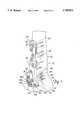
- FIG. 1is a perspective view of an internal fixating system 20 implanted and mounted to distal end 22 of femur 24 having a shaft portion 25 and condyle 26.
- Fixating system 20generally includes: fixator 28, bone screws 30, keyed lag screw 32, compression screw 34, and supplemental lag screws 38.
- Fixator 28is mounted to femur 22 and generally includes plate portion 40, head 44 and tube or barrel 46. As best shown by FIG. 1, plate portion 40 is an elongated member coupled to head 44 and barrel 46. Plate portion 40 is mounted to femur 24 by bone screws 30.
- Fixator 28is preferably formed from a titanium alloy. Alternatively, fixator 28 may be formed from any materials.
- Head 44extends from plate portion near condyles 26 of femur 22. Head 44 is generally circular in shape, somewhat in the shape of a baseball catcher's mitt and includes barrel portion 48 and support portion 50. Barrel portion 48 is generally the central portion of head 44 and supports barrel 46 and keyed lag screw 32. As can be appreciated, barrel portion 48 may alternatively be off set or eccentric.
- Support portion 50extends outward from barrel portion 48 and Generally away from plate portion 40. Support portion 50 supports and maintains supplemental lag screws 38. Supplemental lag screws 38 extend through support portion 50 and extend across comminuted fracture lines into smaller bone fragments. Supplemental lag screws 38 threadably engage bone fragments to pull the bone fragments toward support portion 50 of head 44. As a result, smaller bone fragments are also compressed and fixed by supplemental lag screws 38. Support portion 50 further provides a buttressing surface for abutting femur 24 adjacent condyles 26.
- Barrel 46is generally tubular in shape and extends from head 44 into femur 24. Preferably, barrel 46 does not extend across a vertical fracture line. Barrel 46 slidably receives keyed lag screw 32. Barrel 46 preferably has an inner diameter sized in close tolerance with an outer diameter of keyed lag screw 32 to prevent wobbling or inadvertent movement of keyed lag screw 32 within barrel 46. Barrel 46 rigidly supports keyed lag screw 32 with respect to fixator 28. As a result, barrel 46 provides additional strength to the compression and fixation of the main bone fragments separated by a vertical fracture line.
- Keyed lag screw 32includes a keyed end (not shown) slidably received within barrel 46 of fixator 28. Keyed lag screw 32 extends across a vertical fracture line and threadably engages main bone fragments separated by a vertical fracture line. Keyed lag screw 32 further includes a threaded inner bore (not shown in FIG. 1) partially extending into the keyed end and sized for threadably receiving compression screw 34. Keyed lag screw 32 is preferably formed from pure titanium or an alloy thereof. Alternatively, keyed lag screw 32 may be replaced with a keyless lag screw which includes a smooth cylindrical keyless end (not shown) slidably received within barrel 46 of fixator 28.
- Compression screw 34is conventionally known and extends through barrel 46. Compression screw 34 is threadably received within the threaded inner bore of keyed lag screw 32. Rotation of compression screw 34 causes the keyed end of keyed lag screw 32 to retract within barrel 46 towards head 44 and plate portion 40 of the fixator to compress main bone fragments of condyle 26 towards one another. Barrel 46 guides the retraction of lag screw 32 during compression of the bone fragments. Compression screw 34 is preferably formed from a titanium or an alloy thereof.
- Fixator 28is versatile and provides strong, stable support for fixing and compressing bone fractures. Barrel 46 of fixator 28 provides increased strength for fixing and compressing main bone fragments. Because support portion 50 extends partially about barrel 46 and provides additional buttressing area in contact with femur 24, support portion 50 better stabilizes head 44 of fixator 28 on the surface of condyles 26 of femur 24. In addition, support portion 50 adds versatility to the use of fixator 28. Because support portion 50 of head 44 provides a buttressing surface for supporting supplemental lag screws 38, fixator 28 is also capable of fixing and compressing smaller bone fragments caused by comminuted fractures. Fixator 28 may be used to solely fix and compress main bone fragments caused by a vertical fracture line. If necessary, fixator 28 may also be utilized to fix and compress additional smaller bone fragments by using supplemental lag screws 38.
- FIGS. 2-4illustrate fixator 28 of FIG. 1 in greater detail.
- FIG. 2is a perspective view of fixator 28.
- FIG. 3is a top plan view of fixator 28.
- FIG. 4is a cross-sectional view of fixator 28.
- plate portion 40 of fixator 28is a generally elongated member defining apertures 60 and having a first side 70, a second side 72, a bottom surface 74, a top surface 76, a proximal end 78 and a distal end 80.
- the bottom surface 74 of plate portion 40is preferably contoured so as to abut and conform with the curved surface of femur 24 (shown in FIG. 1).
- bottom surface 74is concave along a line parallel to a length of plate portion 40.
- Top surface 76is preferably flattened along its length to provide a flatter, lower profile when implanted adjacent the surface of femur 24.
- Apertures 60extend through plate portion between bottom surface 74 and top surface 76 and are sized for receiving bone screws 30 (shown in FIG. 1) so that fixator 28 may be secured to shaft portion 25 of femur 24.
- Apertures 60are preferably provided with counter sunk holes 82 sized for receiving heads of bone screws 30.
- the contour of fixator 28 along top surface 76has a low, smooth profile.
- Distal end 80 of plate portion 40preferably extends towards top surface 76 at an angle of about 164° with respect to the plane of the proximal end of plate portion.
- head 44is raised with respect to plate portion 40 and conforms better to the shape of the distal end 22 of femur 24 and condyles 26 (shown in FIG. 1).
- Head 44integrally extends from distal end 80 of plate portion 40.
- headmay be fixed or slidably coupled to plate portion 40 for modular assembly and adjustment of the length of fixator 28.
- barrel portion 48 of head 44comprises a portion of head 44 immediately surrounding and circumjacent to barrel 46.
- Barrel portion 48is preferably centrally located along an axial center line of plate portion 40.
- Barrel portion 48defines a central bore 86 in communication with barrel 46.
- barrel portion 48may alternatively be off-set with respect to the axial center line of plate portion 40 and the center of head 44.
- Support portion 50comprises the portion of head 44 extending from barrel portion 48 away from plate portion 40.
- support portion 50extends beyond both first and second sides 70 and 72 of plate portion 40 and distally away from distal end 80 of plate portion 40.
- Support portion 50is preferably in the shape of a baseball catcher's mitt and includes circular portion 88 and thumb portion 90.
- Circular portion 88extends away from first side 70 of plate portion and preferably has a radius greater than one-half of a width of plate portion 40 between first side 70 and second side 72.
- Circular portion 88preferably extends from first side 70 of plate portion 40 to a location between about 135° and 180° from the axial center line of plate portion 40.
- Thumb portion 90 of the "catcher's mitt" configurationextends from barrel portion 48 away from second side 72 of plate portion 40.
- thumb portion 90extends from second side 72 of plate portion 40 in a direction between about 130° and 150° from a axial center line of plate portion 40.
- Circular portion 88 and thumb portion 90are separated by a notch or gap 92 formed on a distal end 94 of head 44 opposite plate portion 40.
- Gap 92is preferably positioned and sized to accommodate a popliteus muscle or cruciate ligament of the knee joint.
- Circular portion 88 and thumb portion 90 of support portion 50define a plurality of apertures 98 for receiving supplemental lag screws 38 (shown in FIG. 1).
- Apertures 98extend through support portion 50 and preferably include counter-sunk holes 100 for receiving heads of supplemental lag screws 38. Apertures 98 are preferably positioned circumjacent barrel portion 48, central bore 86 and barrel 46. Because apertures are circumferentially positioned about bore 86 of head 44 and barrel 46, stress from lag screws 38 is evenly distributed about barrel 46 and head 44. Because circular portion 88 and thumb portion 90 of support portion 50 provide locations for supporting a plurality of lag screws 38 about barrel 46, multiple smaller bone fractures may be fixed and compressed by supplemental lag screws 38 in conjunction with the stronger compression of a vertical fracture line provided by barrel 46. As best shown by FIG.
- support portion 50 of head 44preferably has a concave bottom surface 96 for abutting a surface of the condyle. As a result, support portion 50 better stabilizes head 44 of fixator 28 for more secure positioning of fixator 28 against the bone and for more secure positioning of supplemental lag screws 38 (shown in FIG. 1) in the fractured bone.
- support portion 50 of headmay have any one of a variety of shapes and configurations.
- support portionmay alternatively comprise a single arm or a plurality of arms or fingers projecting from central portion 50 in any one of various directions away from barrel portion 48 and plate portion 40.
- FIG. 5is a cross-sectional view of barrel 46 taken along line 5--5 of FIG. 4.
- barrel 46is generally tubular in shape and includes a wall 102 which defines a generally cylindrical inner surface 104 and which has a substantially annular cross-section.
- Inner surface 104includes arcuate portions 106 and detents 108.
- Arcuate portions 106 of inner surface 104extend between detents 108 and partially define a generally circular bore 110 through barrel 46 for the reception of a lag screw.
- Bore 110 of barrel 46is in communication with central bore 86 of head 44.
- Arcuate portions 106 of surface 104are concentrically spaced from a center of bore 110 so as to have an inner diameter in close tolerance with an outer diameter of the lag screw received within bore 110.
- Arcuate portions 106 of surface 104engage the lag screw to concentrically center the lag screw within bore 110 for guiding the lag screw within barrel 46 and for preventing substantial radial movement of the lag screw within barrel 46.
- Detents 108are formed along inner surface 104 between arcuate portions 106. Detents 108 generally comprise depressions or notches extending from arcuate portion 106 of surface 104 outward into wall 102 away from the center of bore 110. Detents 108 extend from a lower end 112 of barrel 46 towards head 44 along the entire length of barrel 46. Each detent 108 defines an elongated keyway along inner surface 104 of barrel 46. Detents 108 are shaped, sized and radially located for receiving keys or lugs on lag screws 32.
- Each detent 108receives a key or lug projecting from a lag screw when the lag screw is inserted into bore 110 through end 112 so that barrel 46 and the particular lag screw may engage one another in a slidable yet non-rotatable fashion to prevent rotation of the lag screw and its coupled bone fragments with respect to barrel 46 and fixator 28.
- barrel 46includes two opposite detents 108 extending into wall 102 for receiving a pair of opposite keys or lugs on a lag screw.
- barrel 46may alternatively have one or several detents 108 formed within wall 102.
- barrel 46 of fixator 28is usable with both keyed and keyless lag screws.
- Barrel 46 of fixator 28provides an orthopedic surgeon flexibility in the selection of keyed and non-keyed barrel-lag screw configurations. Consequently barrel 46 of fixator 28 enables a single inventory of versatile fixators 28 to be maintained regardless of whether keyed or keyless lag screws are selected for fixing a bone fragment.
- FIGS. 6-8illustrate keyed lag screw 32 in greater detail.
- FIG. 6is a fragmentary cross-sectional view of keyed lag screw 32.
- FIG. 7is a cross-sectional view of keyed lag screw 32 taken along line 7--7 of FIG. 6.
- FIG. 8is a top plane view of keyed lag screw 32.
- barrel 46 of fixator 28shown in FIGS. 2-5) is capable of slidably receiving keyed lag screw 32.
- keyed lag screw 32includes threaded end 126, keyed end 128 and bore 130. Threaded end 126 includes threads 132 for being threaded into a main bone fragment for fixing and lagging the main bone fragment for compression.
- Keyed end 128extends from threaded end 126 and includes a generally smooth cylindrical outer surface 134, lugs or keys 136a-136d and depressions 135. Cylindrical outer surface 134 circumferentially extends around keyed end 128 axially between keys 136a, 136c and keys 136b, 136d, axially between keys 136b, 136d and threaded end 126, and axially between keys 136a,136c and an end of keyed end 128. Outer surface 134 has a diameter equal or slightly less than the diameter of arcuate portions 106 of barrel 46 (shown in FIG. 5). Outer surface 134 engages arcuate portions 106 to rigidly secure keyed lag screw 32 within barrel 46.
- Depressions 135circumferentially extend around keyed end 128 circumferentially between keys 136a-136d. Depressions 135 preferably have a maximum depth of about 0.003 inches and an axial length slightly larger than the axial length of keys 136. Depressions 135 reduce friction between keyed end 128 of shaft 32 and barrel 46 of fixator 28. As a result, lag screw 32 is more easily inserted into barrel 46 and more easily retracted during compression of the main bone fragments.
- Keys 136a-136dextend outward away from an axial center line of lag screw 32. Keys 136a-136d have a height equal to or less than the depth of detents 108 of barrel 46 (shown in FIG. 5). Keys 136a-136d have a minimum height above surface 134 sufficient to enable keys 136a-136d to adequately engage wall 102 of barrel 46 (shown in FIG. 5) to prevent rotation of lag screw 32. In the preferred embodiment, keys 136a-136d have a height of about 0.014 inches from the floor of depression 135. Each key 136a-136d preferably has an axial length of about 0.2 inches and a circumferential length of about 0.12 inches.
- Keys 136a and 136b and keys 136c and 136dare in axial alignment. Keys 136a and 136c and keys 136b and 136d are in circumferential alignment. Because lag screw 32 includes a pair of keys (keys 136a and 136c or keys 136b and 136d) positioned circumferentially opposite one another, keys 136 are less likely to slip out of detents 108 due to manufacturing tolerances. Keys 136a and 136b are preferably axially spaced from one another. Similarly, keys 136c and 136d are also axially spaced from one another.
- keys 136are always aligned within a keyway formed by detents 108 so that keys 136 prevent accidental rotation of lag screw 32.
- keys 136a-136dare axially spaced from one another keys 136a-136d have less surface area in contact with barrel 46.
- keys 136a-136dproduce less friction and are more easily moved axially within barrel 46 during insertion and compression.
- keys 136a-136drequire less material and have a lower weight once implanted across the fractured femur.
- keys 136may have a variety of circumferential and axial configurations.
- keys 136may alternatively extend along the entire axial length of keyed end 128 and may also alternatively comprise any of a number of circumferentially spaced lugs or keys 136.
- Bore 130extends from an end opposite threaded end 126 axially into and along an axial center line of lag screw 32. Bore 130 is internally threaded and sized for the reception of a compression screw. Inner bore 130 receives a compression screw so that rotation of the compression screw causes keyed lag screw 32 to retract such that threads 132 engage the bone fragment to retract the bone fragment for compression.
- FIG. 9illustrates a keyless lag screw 140 for use with fixator 28 of fixating system 20.
- FIG. 9is a fragmentary cross-sectional view of keyless lag screw 140.
- Keyless lag screw 140is identical to keyed lag screw 32 except that keyed end 128 of keyed lag screw 32 is replaced with keyless end 142.
- Keyless end 142extends from threaded end 126 and forms a generally smooth cylindrical outer surface 144.
- Surface 144has an outer diameter similar to surface 134 of keyed lag screw 32.
- Surface 144preferably has an outer diameter less than or equal to arcuate surface 106.
- keyless end 142 of keyless lag screw 140does not include keys.
- keyless lag screw 140is rotatable within barrel 46 (shown in FIG. 5).
- keyless lag screw 140is easier to align with fixator 28 (shown in FIGS. 2-5) and is easier implant within the fractured femur.
- surface 144 of keyless lag screw 140has an outer diameter substantially equal to that of surface 134 of keyed lag screw 32, both keyed lag screw 32 and keyless lag screw 140 are insertable within bore 110 of barrel 46.
- both lag screws 32 and 140are usable with fixator 128 to provide greater versatility and flexibility in the selection of either keyed or keyless configurations.
- FIGS. 10 and 11illustrate keyed lag screw 32 inserted within femur 24 and within barrel 46 of fixator 28.
- FIG. 10is a fragmentary cross-sectional view of fixating apparatus 20 assembled and mounted adjacent to distal end 22 of femur 24.
- FIG. 11is a cross-sectional view of barrel 46 and lag screw 32 taken along line 11--11 of FIG. 10.
- femur 24is fractured about a vertical fracture line 1 50 and a comminuted fracture line 152 so as to form main bone fragments 154 and 156 and a smaller bone fragment 158.
- Keyed lag screw 32 and supplemental lag screws 38fix and compress bone fragments 154, 156 and 158.
- threads 132 of threaded portion 126 of lag screw 32extend into main bone fragment 154.
- barrel 46 of fixator 28slidably receives keyed end 128 of lag screw 32 in the axial direction (left-to-right as shown in FIG. 10).
- detents 108slidably receive keys 136 of lag screw 32 to prevent rotation of lag screw 32 and main bone fragment 154 with respect to barrel 46 and main bone fragment 156.
- Arcuate portions 106engage outer surface 134 of lag screw 32 to prevent inadvertent radial movement of lag screw 32 and main bone fragment 154 with respect to barrel 46 and main bone fragment 156. Arcuate portions 106 further guide axial movement of lag screw 32 during compression of lag screw 32.
- barrel 46provides a strong and rigid support of lag screw 32 for better fixation and compression of main bone fragments 154 and 156.
- keyless lag screw 140may be used in place of keyed lag screw 32.
- lag screw 32is threadably fastened to condyle 26 of bone fragment 154.
- Barrel 46 of fixator 28is assembled over lag screw 32.
- Compression screw 34extends within and threadably engages threaded bore 130 of lag screw 32. Rotation of compression screw 34 retracts keyed end 128 of lag screw 32 within barrel 46 to retract threaded end 126 towards fixator 28. As a result, main bone fragment 154 is retracted and compressed against main bone fragment 156.
- Supplemental lag screw 38extends through support portion 50 circumjacent barrel 46 and barrel portion 48 of head 44.
- Supplemental lag screwincludes a keyless end 164 and a threaded end 166. Threaded end 166 of supplemental lag screw 38 extends into bone fragment 158. Rotation of supplemental lag screw 38 causes bone fragment 158 to retract towards support portion 50 of head 44. Lag screw 38 further fixes bone fragment 158 in place.
- Fixator 28is mounted along a shaft portion 25 of femur 24 by bone screws 30. Because fixator 28 is configured for fixing bone fractures in the distal end 22 of femur 24 (knee fractures), barrel 46 extends from fixator 28 at between about 85° to about 100°. Preferably, barrel 46 extends from head 44 of fixator 28 at about 95° with respect to plate portion 40.
- fixator 28is capable of receiving both keyed and keyless lag screws as shown in FIGS. 6 and 7.
- fixator 28is versatile and reduces fixator inventories required for both keyed and keyless configurations.
- Barrel 46 and lag screw 32provide a more rigid and strong compression and fixation of main bone fragments 154 and 156.
- head 44 of fixator 28includes support portion 50 extending from barrel portion 48 away from plate portion 40, head 44 additionally buttresses condyle 26 and supports supplemental lag screws 38 for fixing and compressing smaller bone fragments caused by comminuted fracture lines.
- FIGS. 12 and 13illustrate an alternate embodiment (fixator 170) of fixator 28 shown in FIGS. 2-5.
- FIG. 12is a cross sectional view of fixator 170.
- FIG. 13is a cross-sectional view of fixator 170 taken along lines 13--13 of FIG. 12.
- Fixator 170is similar to fixator 28 except that head 44 and barrel 46 of fixator 28 are replaced with head 174 and barrel 176, respectively.
- Head 174 of fixator 170includes a barrel portion 180 which defines a central bore 182. Barrel portion 180 supports barrel 176.
- Barrel 176preferably integrally extends from barrel portion 180 of head 174.
- Barrel 176is similar to barrel 46 except that barrel 176 extends from head 174 at an angle of between about 130° to about 150° with respect to plate portion 40.
- barrel 176extends from head 174 at an angle of about 135° with respect to plate portion 40.
- barrel 176is oriented at an angle for supporting a lag screw for fixing and compressing bone fractures in a proximal end of the femur (hip fractures).
- barrel 176 of fixator 170includes a wall 102 which defines generally cylindrical inner surface 104 having a substantially annular cross-section.
- Inner surface 104includes arcuate portions 106 and detents 108.
- each detent 108receives a key or lug projecting from a lag screw when the lag screw is inserted into bore 106 so that barrel 176 and the particular lag screw may engage one another in a slidable yet non-rotatable fashion to prevent rotation of the lag screw and its coupled bone fragments with respect to barrel 176 and fixator 170.
- detents 108extend into wall 102 of barrel 176, detents 108 do not obtrude into the generally circular cross-section of bore 110 substantially defined by arcuate portions 106.
- bore 110is also capable of receiving smooth, cylindrical keyless ends of non-keyed lag screws.
- barrel 176 of fixator 170provides an orthopedic surgeon flexibility in the selection of keyed and non-keyed barrel-lag screw configurations.
- Barrel 176 of fixator 170enables a single inventory of versatile fixators 170 to be maintained regardless of whether keyed or keyless lag screws are selected for fixing a bone fragment.
- FIGS. 14-16illustrate keyed lag screw 32 inserted within barrel 176 of fixator 170.
- barrel 176supports lag screw 32 at an angle of about 135° with respect to plate portion 40 for fixing and compressing bone fragments at a proximal end of the femur.
- Detents 108prevent rotation of lag screw 32 with respect to barrel 176.
- fixator 170may receive a keyless lag screw such as that illustrated in FIG. 9. Use of a keyless lag screw facilitates faster and easier placement of fixator 170 upon the lag screw and the femur.
Landscapes
- Health & Medical Sciences (AREA)
- Orthopedic Medicine & Surgery (AREA)
- Surgery (AREA)
- Life Sciences & Earth Sciences (AREA)
- Heart & Thoracic Surgery (AREA)
- Nuclear Medicine, Radiotherapy & Molecular Imaging (AREA)
- Engineering & Computer Science (AREA)
- Biomedical Technology (AREA)
- Neurology (AREA)
- Medical Informatics (AREA)
- Molecular Biology (AREA)
- Animal Behavior & Ethology (AREA)
- General Health & Medical Sciences (AREA)
- Public Health (AREA)
- Veterinary Medicine (AREA)
- Surgical Instruments (AREA)
Abstract
Description
The present invention relates to internal bone fracture fixators. In particular, the present invention relates to a bone fracture fixator having a barrel configured for receiving both keyed and keyless lag screws.
The femur, otherwise known as the thigh bone, generally comprises an elongate shaft extending from the hip to the knee. The proximal end of the shaft includes a head, a neck, a greater trochanter and a lesser trochanter. The head of the femur fits into a concavity of the hip bone to form a ball and socket joint at the hip. The distal end of the femur includes a medial condyle and a femoral condyle. The condyles engage an upper end of the tibia to form the knee joint. Overall, the femur is the longest and strongest bone in the skeleton. However, portions of the femur are extremely susceptible to fracturing.
Fractures of the femur occur in both the proximal portion of the femur and the distal portion of the femur. Fractures of the proximal portion of the femur (hip fractures) are generally classified as femoral neck fractures, intertrochanteric fractures and subtrochanteric fractures. Fractures of the distal portion of the femur (knee fractures) are referred to as supracondylar fractures. Supracondylar fractures generally extend vertically between the condylars at the lower end of the femur to separate the distal portion of the femur into two main bone fragments. This fracture line may be further comminuted to create a plurality of smaller bone fragments.
Operational treatment of the fractures requires that the fractures be internally fixed and possibly compressed. Typically, the fractures are fixed and compressed with a lag screw inserted across the particular fracture line and supported by a plate mounted along the shaft of the bone or femur. When the proximal portion or the distal portion of the femur is fractured into two main bone fragments, a tube-plate fixator comprising a plate having a tube or barrel extending from a lower end of the plate is utilized to fix and compress the main bone fragments. The tube slidably receives an end of the lag screw. In such arrangements, the lag screw further includes a threaded interior for threadably receiving a compression screw. The compression screw is inserted through the tube and into the threaded bore of the lag screw so that rotation of the compression screw retracts the lag screw towards the plate to compress the two main bone fragments.
Although conventional tube-plate fixators provide rigid support for fixing and compressing the two main bone fragments caused by a vertical fracture line, conventional tube-plate fixators are not capable of fixing the plurality of additional smaller bone fragments created by comminuted fracture lines. Because tube-plate fixators support only one lag screw, the tube-plate fixator is capable of only fixing one main vertical fracture line. Furthermore, because the portion of the plate supporting the tube has a deminimus area, conventional tube-plate fixators lack sufficient buttressing area for adequately stabilizing the additional smaller bone fragments caused by comminuted fracture lines. In cases where the fracture lines are further comminuted to create a plurality of additional smaller bone fragments, fracture plates are used in lieu of conventional tube-plate fixators. Fracture plates mount to the femur and define a plurality of apertures at one end for supporting a plurality lag screws.
Typically, tube-plate fixators have one of two distinct barrel-lag screw configurations to fix and compress vertical fractures: keyless and keyed barrel-lag screw configurations. Keyless barrel-lag screw configurations utilize barrels with generally cylindrical inner surfaces and lag screws having corresponding cylindrical ends which are slidable and rotatable within the barrels. Because the lag screw is rotatable within the barrel, the barrel may be easily positioned over an end of the lag screw once the lag screw is screwed into the fractured bone. As a result, placement of the fixators is simplified.
Although simpler to implant, keyless barrel-lag screw configurations permit the lag screw and the coupled bone fragments to rotate with respect to the barrel. Once the lag screw is inserted across the vertical fracture line, the lag screw is subject to extreme forces which may cause the lag screw and its coupled bone fragments to rotate with respect to the barrel or tube of the plate. To prevent undesirable rotation of bone fragments, the lag screws and barrels are keyed to one another. The keyed configuration prevents rotation of the lag screw with respect to the barrel by forming a protuberance on the generally cylindrical inner surface of the barrel and by forming a corresponding detent on the cylindrical outer surface of the lag screw so that the end of the lag screw and the barrel mate in a non-rotatable relationship. For example, a keyed barrel-lag screw configuration may comprise a barrel having a rectangular inner surface and a lag screw having a rectangular outer surface to prevent rotation of the lag screw with respect to the barrel. Although keyed tube-lag screw configurations prevent rotation of the lag screw with respect to the barrel, placement of the plate and the barrel adjacent the femur and over the end of the lag screw is more difficult because the corresponding non-cylindrical shapes require the inner surface of the barrel and the outer surface of the lag screw to be in exact alignment for the end of the lag screw to be received within the barrel.
Present day keyless and keyed barrel-lag screw configurations have one severe drawback, lack of interchangeability. Because the barrel of a keyed barrel-lag screw configuration includes a protuberance or obtrusive portion projecting into the bore of the barrel for keying with a keyed lag screw, the keyed barrel of the fixator cannot receive the generally smooth cylindrical end of a keyless lag screw. Thus, separate fixators are required to accommodate keyed and keyless lag screws. As a result, separate inventories of relatively expensive, space consuming fixators for both configurations must be maintained.
The present invention is an improved system for internally fixing bone fractures. The system includes a fixator having a barrel with a cylindrical inner surface for rotatably and slidably receiving a cylindrical end of a keyless lag screw. The cylindrical inner surface further defines a keyway along at least a portion of the length of the barrel for allowing the barrel to slidably receive a keyed lag screw to prevent rotation of the keyed lag screw. As a result, the fixator of the present invention is usable with both keyed and non-keyed lag screws.
FIG. 1 is a perspective view of an internal fixating system mounted to a distal end of a femur.
FIG. 2 is a perspective view of a fixator of the internal fixating system of FIG. 1.
FIG. 3 is a top plan view of the fixator.
FIG. 4 is a cross-sectional view of the fixator.
FIG. 5 is a cross-sectional view of the fixator taken along line 5--5 of FIG. 4.
FIG. 6 is a fragmentary cross-sectional view of a keyed lag screw of the internal fixating system of FIG. 1.
FIG. 7 is a cross-sectional view of the keyed lag screw taken along line 7--7 of FIG. 6.
FIG. 8 is a top plan view of the keyed lag screw.
FIG. 9 is a fragmentary cross-sectional view of a keyless lag screw.
FIG. 10 is a cross-sectional view of the internal fixating system mounted to a distal end of a femur.
FIG. 11 is a cross-sectional view of the internal fixating system taken alongline 11--11 of FIG. 10.
FIG. 12 is a cross-sectional view of an alternate embodiment of the fixator of FIGS. 2-5.
FIG. 13 is a cross-sectional view of the fixator taken alongline 13--13 of FIG. 12.
FIG. 14 is a perspective view of the keyed lag screw of FIGS. 6-8 coupled to the fixator of FIG. 12.
FIG. 15 is a top plan view of the lag screw and fixator of FIG. 14.
FIG. 16 is a partial cross-sectional view of the lag screw and fixator of FIG. 14.
FIG. 1 is a perspective view of aninternal fixating system 20 implanted and mounted todistal end 22 offemur 24 having ashaft portion 25 andcondyle 26. Fixatingsystem 20 generally includes:fixator 28,bone screws 30,keyed lag screw 32,compression screw 34, andsupplemental lag screws 38.Fixator 28 is mounted tofemur 22 and generally includesplate portion 40,head 44 and tube orbarrel 46. As best shown by FIG. 1,plate portion 40 is an elongated member coupled tohead 44 andbarrel 46.Plate portion 40 is mounted tofemur 24 by bone screws 30.Fixator 28 is preferably formed from a titanium alloy. Alternatively,fixator 28 may be formed from any materials.
FIGS. 2-4 illustratefixator 28 of FIG. 1 in greater detail. FIG. 2 is a perspective view offixator 28. FIG. 3 is a top plan view offixator 28. FIG. 4 is a cross-sectional view offixator 28. As best shown by FIGS. 2-4,plate portion 40 offixator 28 is a generally elongatedmember defining apertures 60 and having afirst side 70, asecond side 72, abottom surface 74, atop surface 76, aproximal end 78 and adistal end 80. Thebottom surface 74 ofplate portion 40 is preferably contoured so as to abut and conform with the curved surface of femur 24 (shown in FIG. 1). Preferably,bottom surface 74 is concave along a line parallel to a length ofplate portion 40.Top surface 76 is preferably flattened along its length to provide a flatter, lower profile when implanted adjacent the surface offemur 24.Apertures 60 extend through plate portion betweenbottom surface 74 andtop surface 76 and are sized for receiving bone screws 30 (shown in FIG. 1) so thatfixator 28 may be secured toshaft portion 25 offemur 24.Apertures 60 are preferably provided with counter sunkholes 82 sized for receiving heads of bone screws 30. As a result, the contour offixator 28 alongtop surface 76 has a low, smooth profile.
FIG. 5 is a cross-sectional view ofbarrel 46 taken along line 5--5 of FIG. 4. As best shown by FIG. 5,barrel 46 is generally tubular in shape and includes awall 102 which defines a generally cylindricalinner surface 104 and which has a substantially annular cross-section.Inner surface 104 includesarcuate portions 106 anddetents 108.Arcuate portions 106 ofinner surface 104 extend betweendetents 108 and partially define a generallycircular bore 110 throughbarrel 46 for the reception of a lag screw. Bore 110 ofbarrel 46 is in communication withcentral bore 86 ofhead 44.Arcuate portions 106 ofsurface 104 are concentrically spaced from a center ofbore 110 so as to have an inner diameter in close tolerance with an outer diameter of the lag screw received withinbore 110.Arcuate portions 106 ofsurface 104 engage the lag screw to concentrically center the lag screw withinbore 110 for guiding the lag screw withinbarrel 46 and for preventing substantial radial movement of the lag screw withinbarrel 46.
Becausedetents 108 extend intowall 102 ofbarrel 46,detents 108 do not obtrude into the generally circular cross-section ofbore 110 substantially defined byarcuate portions 106. As a result, bore 110 is also capable of receiving smooth, cylindrical keyless ends of non-keyed lag screws. Thus,barrel 46 offixator 28 is usable with both keyed and keyless lag screws.Barrel 46 offixator 28 provides an orthopedic surgeon flexibility in the selection of keyed and non-keyed barrel-lag screw configurations. Consequentlybarrel 46 offixator 28 enables a single inventory ofversatile fixators 28 to be maintained regardless of whether keyed or keyless lag screws are selected for fixing a bone fragment.
FIGS. 6-8 illustrate keyedlag screw 32 in greater detail. FIG. 6 is a fragmentary cross-sectional view of keyedlag screw 32. FIG. 7 is a cross-sectional view of keyedlag screw 32 taken along line 7--7 of FIG. 6. FIG. 8 is a top plane view of keyedlag screw 32. As discussed above,barrel 46 of fixator 28 (shown in FIGS. 2-5) is capable of slidably receiving keyedlag screw 32. As shown by FIG. 6, keyedlag screw 32 includes threadedend 126, keyedend 128 and bore 130. Threadedend 126 includesthreads 132 for being threaded into a main bone fragment for fixing and lagging the main bone fragment for compression.
Keys 136a-136d extend outward away from an axial center line oflag screw 32. Keys 136a-136d have a height equal to or less than the depth ofdetents 108 of barrel 46 (shown in FIG. 5). Keys 136a-136d have a minimum height abovesurface 134 sufficient to enable keys 136a-136d to adequately engagewall 102 of barrel 46 (shown in FIG. 5) to prevent rotation oflag screw 32. In the preferred embodiment, keys 136a-136d have a height of about 0.014 inches from the floor ofdepression 135. Each key 136a-136d preferably has an axial length of about 0.2 inches and a circumferential length of about 0.12 inches.Keys 136a and 136b andkeys 136c and 136d are in axial alignment. Keys 136a and 136c andkeys lag screw 32 includes a pair of keys (keys 136a and 136c orkeys keys 136 are less likely to slip out ofdetents 108 due to manufacturing tolerances.Keys 136a and 136b are preferably axially spaced from one another. Similarly,keys 136c and 136d are also axially spaced from one another. As a result, at least onekey 136 is always aligned within a keyway formed bydetents 108 so thatkeys 136 prevent accidental rotation oflag screw 32. In addition, because keys 136a-136d are axially spaced from one another keys 136a-136d have less surface area in contact withbarrel 46. As a result, keys 136a-136d produce less friction and are more easily moved axially withinbarrel 46 during insertion and compression. In addition, keys 136a-136d require less material and have a lower weight once implanted across the fractured femur. As can be appreciated depending upon the number and circumferential positions ofdetents 108 inbarrel 46,keys 136 may have a variety of circumferential and axial configurations. For example,keys 136 may alternatively extend along the entire axial length ofkeyed end 128 and may also alternatively comprise any of a number of circumferentially spaced lugs orkeys 136.
FIG. 9 illustrates akeyless lag screw 140 for use withfixator 28 of fixatingsystem 20. FIG. 9 is a fragmentary cross-sectional view ofkeyless lag screw 140. For ease of illustration, those elements ofkeyless lag screw 140 which are the same as those elements of keyedlag screw 32 are numbered similarly.Keyless lag screw 140 is identical tokeyed lag screw 32 except thatkeyed end 128 of keyedlag screw 32 is replaced withkeyless end 142.Keyless end 142 extends from threadedend 126 and forms a generally smooth cylindrical outer surface 144. Surface 144 has an outer diameter similar tosurface 134 of keyedlag screw 32. Surface 144 preferably has an outer diameter less than or equal toarcuate surface 106. In contrast tokeyed end 128 of keyedlag screw 32,keyless end 142 ofkeyless lag screw 140 does not include keys. As a result,keyless lag screw 140 is rotatable within barrel 46 (shown in FIG. 5). In addition,keyless lag screw 140 is easier to align with fixator 28 (shown in FIGS. 2-5) and is easier implant within the fractured femur. Because surface 144 ofkeyless lag screw 140 has an outer diameter substantially equal to that ofsurface 134 of keyedlag screw 32, both keyedlag screw 32 andkeyless lag screw 140 are insertable withinbore 110 ofbarrel 46. As a result, both lag screws 32 and 140 are usable withfixator 128 to provide greater versatility and flexibility in the selection of either keyed or keyless configurations.
FIGS. 10 and 11 illustrate keyedlag screw 32 inserted withinfemur 24 and withinbarrel 46 offixator 28. FIG. 10 is a fragmentary cross-sectional view of fixatingapparatus 20 assembled and mounted adjacent todistal end 22 offemur 24. FIG. 11 is a cross-sectional view ofbarrel 46 andlag screw 32 taken alongline 11--11 of FIG. 10. As best shown by FIG. 10,femur 24 is fractured about a vertical fracture line 1 50 and acomminuted fracture line 152 so as to form main bone fragments 154 and 156 and asmaller bone fragment 158.Keyed lag screw 32 and supplemental lag screws 38 fix and compressbone fragments threads 132 of threadedportion 126 oflag screw 32 extend intomain bone fragment 154.
As best shown by FIG. 11,barrel 46 offixator 28 slidably receives keyedend 128 oflag screw 32 in the axial direction (left-to-right as shown in FIG. 10). In particular,detents 108 slidably receivekeys 136 oflag screw 32 to prevent rotation oflag screw 32 andmain bone fragment 154 with respect tobarrel 46 andmain bone fragment 156.Arcuate portions 106 engageouter surface 134 oflag screw 32 to prevent inadvertent radial movement oflag screw 32 andmain bone fragment 154 with respect tobarrel 46 andmain bone fragment 156.Arcuate portions 106 further guide axial movement oflag screw 32 during compression oflag screw 32. Overall,barrel 46 provides a strong and rigid support oflag screw 32 for better fixation and compression of main bone fragments 154 and 156. As can be appreciated,keyless lag screw 140 may be used in place of keyedlag screw 32.
As shown by FIG. 10,lag screw 32 is threadably fastened to condyle 26 ofbone fragment 154.Barrel 46 offixator 28 is assembled overlag screw 32.Compression screw 34 extends within and threadably engages threadedbore 130 oflag screw 32. Rotation ofcompression screw 34 retracts keyedend 128 oflag screw 32 withinbarrel 46 to retract threadedend 126 towardsfixator 28. As a result,main bone fragment 154 is retracted and compressed againstmain bone fragment 156.
As discussed above,barrel 46 offixator 28 is capable of receiving both keyed and keyless lag screws as shown in FIGS. 6 and 7. Thus,fixator 28 is versatile and reduces fixator inventories required for both keyed and keyless configurations.Barrel 46 andlag screw 32 provide a more rigid and strong compression and fixation of main bone fragments 154 and 156. In addition, becausehead 44 offixator 28 includessupport portion 50 extending frombarrel portion 48 away fromplate portion 40,head 44 additionally buttressescondyle 26 and supports supplemental lag screws 38 for fixing and compressing smaller bone fragments caused by comminuted fracture lines.
FIGS. 12 and 13 illustrate an alternate embodiment (fixator 170) offixator 28 shown in FIGS. 2-5. FIG. 12 is a cross sectional view offixator 170. FIG. 13 is a cross-sectional view offixator 170 taken alonglines 13--13 of FIG. 12. For ease of illustration, those elements offixator 170 which are the same as those elements offixator 28 are numbered similarly.Fixator 170 is similar tofixator 28 except thathead 44 andbarrel 46 offixator 28 are replaced withhead 174 andbarrel 176, respectively.Head 174 offixator 170 includes abarrel portion 180 which defines acentral bore 182.Barrel portion 180 supportsbarrel 176.
FIGS. 14-16 illustrate keyedlag screw 32 inserted withinbarrel 176 offixator 170. As shown by FIGS. 14-16,barrel 176 supports lagscrew 32 at an angle of about 135° with respect toplate portion 40 for fixing and compressing bone fragments at a proximal end of the femur.Detents 108 prevent rotation oflag screw 32 with respect tobarrel 176. Alternatively,fixator 170 may receive a keyless lag screw such as that illustrated in FIG. 9. Use of a keyless lag screw facilitates faster and easier placement offixator 170 upon the lag screw and the femur.
Although the present invention has been described with reference to preferred embodiments, workers skilled in the art will recognize that changes may be made in form and detail without departing from the spirit and scope of the invention.
Claims (9)
1. A fixating system for internally fixating bone fractures, the system comprising:
a fixator including:
a plate portion, the plate portion defining at least one plate aperture extending through the plate portion for receiving fastening means to fasten the fixator to a shaft of a bone;
a head portion extending from the plate portion; and
a barrel extending from the head portion, the barrel having a length and a means for receiving at least one of a keyless lag screw and a keyed lag screw, the means defining at least one key way recessed into a cylindrical inner surface of the barrel along at least a portion of a length of the barrel, and
a first keyed lag screw having a threaded end portion for fastening to a bone fragment and a smooth end portion for being slidably received within the barrel, the smooth end portion having a length and an outer surface defining at least one key protruding from and integral and unitary with the outer surface and extending at least partially along the length for being received by the key way of the barrel to prevent rotation of the first lag screw within the barrel; and
a compression screw adapted to be threadably fastened to the smooth end portion of the first lag screw and configured to bear against the head portion of the plate portion to hold the bone fragment in compression.
2. The system of claim 1 wherein the first lag screw includes:
a plurality of spaced keys at least partially along the length of the second smooth end portion.
3. The system of claim 1 further including:
a second lag screw having a threaded end portion and a smooth end portion, the smooth end portion of a second lag screw being rotatable within the barrel of the fixator.
4. The system of claim 1 wherein the inner surface of the barrel of the fixator defines two opposite key ways.
5. The system of claim 1 wherein the first lag screw includes:
two keys oppositely oriented about outer surface of the smooth end portion of the first lag screw.
6. The system of claim 1 wherein the lag screw further includes:
a threaded bore extending through the second smooth end portion, the threaded bore sized for receiving a compression screw.
7. The system of claim 6 wherein the outer surface of the smooth end portion of the first lag screw further includes a depression surrounding each key to reduce sliding friction between the inner surface of the barrel of the fixator and the outer surface of the smooth end portion of the first lag screw.
8. A lag screw for use with an internal bone fracture fixator having a barrel with a cylindrical inner surface along its length with a key way for slidably receiving the lag screw, the lag screw comprising:
a threaded end portion: and
a smooth end portion including means for being slidably received within the barrel of the fixator and having a length, the means including an outer surface defining at least one key protruding at least partially along the length and being unitary with the outer surface for being received by the key way of the barrel of the fixator, and defining a depression extending about a periphery of the outer surface and surrounding each key to reduce sliding friction between the outer surface of the smooth end portion of the lag screw and the barrel of the inner surface of the barrel of the fixator barrel.
9. A fixating kit for internally fixating bone fractures, the kit comprising:
a fixator including:
a plate portion, the plate portion defining at least one plate aperture extending through the plate portion for receiving fastening means to fasten the fixator to a shaft of a bone;
a head portion extending from the plate portion; and
a barrel extending from the head portion, the barrel having a length and a means for receiving at least one of a keyless lag screw and a keyed lag screw, the means defining at least one key way recessed into a cylindrical inner surface of the barrel along at least a portion of the length of the barrel;
a first keyed lag screw having a threaded end portion for fastening to a bone fragment and a smooth end portion for being slidably received within the barrel, the smooth end portion having a length and an outer surface defining at least one key protruding outward from and integral and unitary with the outer surface and extending at least partially along the length for being received by the key way of the barrel to prevent rotation of the first lag screw within the barrel;
a second keyless lag screw having a threaded end portion for fastening to a bone fragment and a smooth end portion for being slidably received within the barrel, the smooth end portion of the second lag screw having a length and an outer surface adapted to be received by the barrel to permit rotation of the second lag screw relative to the barrel; and
a compression screw adapted to be threadably fastened to the smooth end portion of one of the first lag screw and the second lag screw and configured to bear against the head portion of the plate portion to hold the bone fragment in compression,
wherein one of the first lag screw and the second lag screw are inserted within the barrel of the fixator for use in fixating a bone fracture.
Priority Applications (3)
| Application Number | Priority Date | Filing Date | Title |
|---|---|---|---|
| US08/525,853US5749872A (en) | 1995-09-08 | 1995-09-08 | Keyed/keyless barrel for bone plates |
| PCT/US1996/014442WO1997008999A1 (en) | 1995-09-08 | 1996-09-09 | Internal bone fracture fixator |
| AU69713/96AAU6971396A (en) | 1995-09-08 | 1996-09-09 | Internal bone fracture fixator |
Applications Claiming Priority (1)
| Application Number | Priority Date | Filing Date | Title |
|---|---|---|---|
| US08/525,853US5749872A (en) | 1995-09-08 | 1995-09-08 | Keyed/keyless barrel for bone plates |
Publications (1)
| Publication Number | Publication Date |
|---|---|
| US5749872Atrue US5749872A (en) | 1998-05-12 |
Family
ID=24094869
Family Applications (1)
| Application Number | Title | Priority Date | Filing Date |
|---|---|---|---|
| US08/525,853Expired - LifetimeUS5749872A (en) | 1995-09-08 | 1995-09-08 | Keyed/keyless barrel for bone plates |
Country Status (1)
| Country | Link |
|---|---|
| US (1) | US5749872A (en) |
Cited By (156)
| Publication number | Priority date | Publication date | Assignee | Title |
|---|---|---|---|---|
| US6197027B1 (en)* | 1999-09-08 | 2001-03-06 | Mohammed Ali Hajianpour | Device for external fixation of a fractured radius |
| US6221074B1 (en)* | 1999-06-10 | 2001-04-24 | Orthodyne, Inc. | Femoral intramedullary rod system |
| USD443060S1 (en) | 2000-06-01 | 2001-05-29 | Bristol-Myers Squibb Company | Bone plate |
| US6379360B1 (en) | 1998-03-11 | 2002-04-30 | Synthes (Usa) | Spiral blade insertion instrument |
| USD463558S1 (en) | 2001-11-16 | 2002-09-24 | Zimmer, Inc. | Orthopaedic bone plate |
| USD463559S1 (en) | 2001-11-16 | 2002-09-24 | Zimmer, Inc. | Orthopaedic bone plate |
| USD464731S1 (en) | 2001-11-16 | 2002-10-22 | Zimmer, Inc. | Orthopaedic bone plate |
| US20020156474A1 (en)* | 2001-04-20 | 2002-10-24 | Michael Wack | Polyaxial locking plate |
| US20030040748A1 (en)* | 2001-08-24 | 2003-02-27 | Aikins Jerry L. | Blade plate and instruments |
| US6533789B1 (en) | 2000-04-04 | 2003-03-18 | Synthes (Usa) | Device for rotational stabilization of bone segments |
| US6540746B1 (en)* | 1999-09-30 | 2003-04-01 | Sulzer Orthopedics Ltd. | Bone plate for splinting a fracture at a bone with a plurality of bone screws |
| US6585736B2 (en) | 2001-09-19 | 2003-07-01 | Mohammed A. Hajianpour | Device for external fixation of a fractured radius with simultaneous clamping of multiple pins and with a fixture for applying extension to distal bone fragments |
| US6623486B1 (en) | 1999-09-13 | 2003-09-23 | Synthes (U.S.A.) | bone plating system |
| US6645209B2 (en) | 2000-04-04 | 2003-11-11 | Synthes (Usa) | Device for rotational stabilization of bone segments |
| US20040111090A1 (en)* | 2002-10-03 | 2004-06-10 | The University Of North Carolina At Chapel Hill | Modification of percutaneous intrafocal plate system |
| US20040122430A1 (en)* | 2001-05-08 | 2004-06-24 | Henrik Hansson | Implant |
| US20040153073A1 (en)* | 2000-02-01 | 2004-08-05 | Hand Innovations, Inc. | Orthopedic fixation system including plate element with threaded holes having divergent axes |
| US20040181228A1 (en)* | 1999-03-09 | 2004-09-16 | Synthes Ag Chur And Synthes (Usa) | Bone plante |
| US20040193165A1 (en)* | 2003-03-27 | 2004-09-30 | Hand Innovations, Inc. | Anatomical distal radius fracture fixation plate and methods of using the same |
| US20040193164A1 (en)* | 2003-03-27 | 2004-09-30 | Orbay Jorge L. | Anatomical distal radius fracture fixation plate and methods of using the same |
| US20040193163A1 (en)* | 2003-03-27 | 2004-09-30 | Orbay Jorge L. | Bone fracture fixation system with subchondral and articular surface support |
| US20040193155A1 (en)* | 2003-03-27 | 2004-09-30 | Hand Innovations, Inc. | Fracture fixation plate with particular plate hole and fastener engagement and methods of using the same |
| US20040210220A1 (en)* | 2001-07-17 | 2004-10-21 | Alain Tornier | Osteosynthesis plate for the upper end of the arm bone |
| US20040236337A1 (en)* | 2003-04-02 | 2004-11-25 | Benoist Girard Sas | Greater trochanteric re-attachment device |
| US20040260292A1 (en)* | 2000-02-01 | 2004-12-23 | Hand Innovations, Inc. | Fixation system with multidirectional stabilization pegs |
| US20050010226A1 (en)* | 2003-05-30 | 2005-01-13 | Grady Mark P. | Bone plate |
| US20050010224A1 (en)* | 2003-07-07 | 2005-01-13 | Watkins William T. | Compression bone screw device |
| US20050065523A1 (en)* | 2003-03-27 | 2005-03-24 | Orbay Jorge L. | Distal radius fracture fixation plate having K-wire hole structured to fix a K-wire in one dimension relative to the plate |
| WO2005025437A1 (en)* | 2003-09-08 | 2005-03-24 | Smith & Nephew, Inc. | Orthopaedic plate and screw assembly |
| US20050065524A1 (en)* | 2003-03-27 | 2005-03-24 | Orbay Jorge L. | Anatomical distal radius fracture fixation plate with fixed-angle K-wire holes defining a three-dimensional surface |
| US20050065520A1 (en)* | 2002-12-10 | 2005-03-24 | Orbay Jorge L. | Endosteal nail |
| US20050065522A1 (en)* | 2003-03-27 | 2005-03-24 | Orbay Jorge L. | Low profile distal radius fracture fixation plate |
| WO2005027764A1 (en)* | 2003-09-23 | 2005-03-31 | Instituto Tecnologico De Canarias, S.A. (Itc) | Fixing device for hip osteotomies and fractures in children and adolescents |
| US20050099869A1 (en)* | 2003-09-07 | 2005-05-12 | Microsoft Corporation | Field start code for entry point frames with predicted first field |
| US20050101959A1 (en)* | 2000-11-22 | 2005-05-12 | Milorad Mitkovic | Internal fixator of bones |
| US20050165395A1 (en)* | 2004-01-23 | 2005-07-28 | Orbay Jorge L. | System for stabilization of fractures of convex articular bone surfaces including subchondral support structure |
| US20050182406A1 (en)* | 2004-01-23 | 2005-08-18 | Orbay Jorge L. | System for stabilization of fractures of convex articular bone surfaces including subchondral support structure |
| US20050187551A1 (en)* | 2002-12-02 | 2005-08-25 | Orbay Jorge L. | Bone plate system with bone screws fixed by secondary compression |
| US20050240186A1 (en)* | 2000-02-01 | 2005-10-27 | Orbay Jorge L | Bone fracture fixation systems with both multidirectional and unidirectional fixation devices |
| US20060004361A1 (en)* | 2004-06-21 | 2006-01-05 | Garry Hayeck | Bone plate |
| US20060041260A1 (en)* | 2000-02-01 | 2006-02-23 | Orbay Jorge L | Fixation system with plate having holes with divergent axes and multidirectional fixators for use therethrough |
| US7018380B2 (en) | 1999-06-10 | 2006-03-28 | Cole J Dean | Femoral intramedullary rod system |
| US20060100624A1 (en)* | 2000-02-01 | 2006-05-11 | Orbay Jorge L | Intramedullary fixation device for metaphyseal long bone fractures |
| US20060167756A1 (en)* | 2005-01-21 | 2006-07-27 | Ebay Inc. | Network-based commerce facility offer management methods and systems |
| US20060173459A1 (en)* | 2005-01-28 | 2006-08-03 | Kay David B | Orthopedic plate for use in small bone repair |
| US7090676B2 (en) | 2002-11-19 | 2006-08-15 | Acumed Llc | Adjustable bone plates |
| US20060189987A1 (en)* | 2002-05-30 | 2006-08-24 | Orbay Jorge L | Nail plate |
| US20060189996A1 (en)* | 2005-01-28 | 2006-08-24 | Orbay Jorge L | Nail plate and implantation jig therefor |
| US20060217722A1 (en)* | 2003-09-08 | 2006-09-28 | Christof Dutoit | Bone-fixation device |
| US20060235400A1 (en)* | 2003-08-26 | 2006-10-19 | Rolf Schneider | Bone plate |
| US20060235402A1 (en)* | 2005-03-11 | 2006-10-19 | Orthofix International B.V. | Device for the ostheosynthesis of proximal humerus fractures |
| US7153309B2 (en) | 2002-11-19 | 2006-12-26 | Acumed Llc | Guide system for bone-repair devices |
| US20070010818A1 (en)* | 2005-07-06 | 2007-01-11 | Stone Howard A | Surgical system for joints |
| US20070016205A1 (en)* | 2003-10-30 | 2007-01-18 | Florian Beutter | Bone plate |
| US7189237B2 (en) | 2002-11-19 | 2007-03-13 | Acumed Llc | Deformable bone plates |
| CN1309351C (en)* | 2000-05-31 | 2007-04-11 | 西尔瓦纳·韦塞 | A device used to hold a broken bone fragment in place due to a fracture |
| US20070088360A1 (en)* | 2005-09-19 | 2007-04-19 | Orbay Jorge L | Bone stabilization system including multi-directional threaded fixation element |
| EP1797835A1 (en)* | 2005-12-16 | 2007-06-20 | DePuy Products, Inc. | Orthopaedic device with locking barrel |
| US20070233106A1 (en)* | 2006-02-24 | 2007-10-04 | Synthes (Usa) | Tibal plateau leveling osteotomy plate |
| US20070265629A1 (en)* | 2006-03-07 | 2007-11-15 | Amanda Martin | Distal radius plate |
| US20070270845A1 (en)* | 2003-09-08 | 2007-11-22 | Kohsuke Watanabe | Orthopaedic plate and screw assembly |
| WO2007147688A1 (en)* | 2006-06-21 | 2007-12-27 | Königsee Implantate und Instrumente zur Osteosynthese GmbH | Femoral head implant |
| US20070299447A1 (en)* | 2003-09-08 | 2007-12-27 | Kohsuke Watanabe | Orthopaedic plate and screw assembly |
| US20080140130A1 (en)* | 2004-01-26 | 2008-06-12 | Chan Jason S | Highly-versatile variable-angle bone plate system |
| US20080140127A1 (en)* | 2006-12-06 | 2008-06-12 | Amei Technologies, Inc. | Volar plate fixation device |
| US20080221574A1 (en)* | 2007-03-05 | 2008-09-11 | Cesare Cavallazzi | Method of Treating a Clavicle Fracture |
| US20080275508A1 (en)* | 2007-05-04 | 2008-11-06 | Haidukewych George J | Bone end (epiphysis) fracture fixation device and method of use |
| US20080281326A1 (en)* | 2007-03-20 | 2008-11-13 | Kohsuke Watanabe | Orthopaedic plate and screw assembly |
| US7537604B2 (en) | 2002-11-19 | 2009-05-26 | Acumed Llc | Bone plates with slots |
| US7537596B2 (en) | 2003-06-20 | 2009-05-26 | Acumed Llc | Bone plates with intraoperatively tapped apertures |
| US7537603B2 (en) | 2002-07-22 | 2009-05-26 | Acumed Llc | Bone fusion system |
| US7578825B2 (en) | 2004-04-19 | 2009-08-25 | Acumed Llc | Placement of fasteners into bone |
| EP2092904A1 (en)* | 2008-02-22 | 2009-08-26 | Prévôt, Bertrand | Trochanter plate |
| US20090228010A1 (en)* | 2008-03-10 | 2009-09-10 | Eduardo Gonzalez-Hernandez | Bone fixation system |
| US20090306724A1 (en)* | 2005-01-28 | 2009-12-10 | Orthohelix Surgical Designs, Inc. | Orthopedic plates for use in clavicle repair and methods for their use |
| US7635365B2 (en) | 2003-08-28 | 2009-12-22 | Ellis Thomas J | Bone plates |
| US7655029B2 (en) | 2001-05-28 | 2010-02-02 | Synthes Usa, Llc | Bone plate |
| US20100057214A1 (en)* | 2008-09-03 | 2010-03-04 | Mimedx, Inc., Corporation of the State of Florida | Arthrodesis implant for finger joints and related methods |
| US20100076496A1 (en)* | 2004-01-26 | 2010-03-25 | Alberto Angel Fernandez | Variable Angle Locked Bone Fixation System |
| US7695502B2 (en) | 2000-02-01 | 2010-04-13 | Depuy Products, Inc. | Bone stabilization system including plate having fixed-angle holes together with unidirectional locking screws and surgeon-directed locking screws |
| US7717945B2 (en) | 2002-07-22 | 2010-05-18 | Acumed Llc | Orthopedic systems |
| US20100174285A1 (en)* | 2006-10-04 | 2010-07-08 | Robert Probe | Fixation Of Femoral Neck Fractures |
| US7780710B2 (en) | 2004-01-23 | 2010-08-24 | Depuy Products, Inc. | System for stabilization of fractures of convex articular bone surfaces including subchondral support structure |
| US20100217265A1 (en)* | 2009-02-24 | 2010-08-26 | National Yang-Ming University | Anti-subsidence dynamic hip screw |
| US20100217328A1 (en)* | 2009-02-24 | 2010-08-26 | Osteomed L.P. | Multiple Bone Fusion Plate |
| US20100274245A1 (en)* | 2003-11-21 | 2010-10-28 | Eduardo Gonzalez-Hernandez | Fracture fixation system |
| US20100274293A1 (en)* | 2009-04-28 | 2010-10-28 | Osteomed L.P. | Bone Plate with a Transfixation Screw Hole |
| US7846162B2 (en) | 2005-05-18 | 2010-12-07 | Sonoma Orthopedic Products, Inc. | Minimally invasive actuable bone fixation devices |
| US20110066152A1 (en)* | 2009-09-14 | 2011-03-17 | Zimmer, Gmbh | Angular lag implant for intramedullary nails |
| US7909825B2 (en) | 2006-11-22 | 2011-03-22 | Sonoma Orthepedic Products, Inc. | Fracture fixation device, tools and methods |
| US20110118741A1 (en)* | 2005-05-12 | 2011-05-19 | Jin Gon Kim | Apparatus for preventing distal migration of lag screw for hip fracture surgery |
| US20110152943A1 (en)* | 2009-12-22 | 2011-06-23 | Eduardo Gonzalez-Hernandez | Bone plate and tool assembly and method for use thereof |
| US20110152864A1 (en)* | 2009-12-18 | 2011-06-23 | Emil Schemitsch | Bone fixation system |
| US20110202138A1 (en)* | 2009-08-27 | 2011-08-18 | The Foundry Llc | Method and Apparatus for Force Redistribution in Articular Joints |
| US20110218533A1 (en)* | 2010-03-08 | 2011-09-08 | Bernard Prandi | Radius-plate assembly |
| US20110218534A1 (en)* | 2010-03-08 | 2011-09-08 | Bernard Prandi | Adjustable-angle radius plate |
| US20110224671A1 (en)* | 2009-09-14 | 2011-09-15 | Kenny Koay | Variable angle compression plate |
| JP2011245306A (en)* | 2010-05-25 | 2011-12-08 | Stryker Trauma Sa | Implant for bone fixation |
| US8105367B2 (en) | 2003-09-29 | 2012-01-31 | Smith & Nephew, Inc. | Bone plate and bone plate assemblies including polyaxial fasteners |
| US8118848B2 (en) | 2005-01-28 | 2012-02-21 | Orthohelix Surgical Designs, Inc. | Orthopedic plate for use in fibula repair |
| US8177819B2 (en) | 2004-04-22 | 2012-05-15 | Acumed Llc | Expanded fixation of bones |
| US8287541B2 (en) | 2005-05-18 | 2012-10-16 | Sonoma Orthopedic Products, Inc. | Fracture fixation device, tools and methods |
| US20130006246A1 (en)* | 2011-06-30 | 2013-01-03 | Dodson Mark | Distal Radius Plate |
| US8382807B2 (en) | 2005-07-25 | 2013-02-26 | Smith & Nephew, Inc. | Systems and methods for using polyaxial plates |
| US8449544B2 (en) | 2009-06-30 | 2013-05-28 | Smith & Nephew, Inc. | Orthopaedic implant and fastener assembly |
| US8469999B2 (en) | 2008-04-17 | 2013-06-25 | Eduardo Gonzalez-Hernandez | Soft tissue attachment system and clip |
| US8568417B2 (en) | 2009-12-18 | 2013-10-29 | Charles River Engineering Solutions And Technologies, Llc | Articulating tool and methods of using |
| US20140066998A1 (en)* | 2012-09-06 | 2014-03-06 | Jean-Jacques Martin | Assembly comprising an implantable part designed to be fastened to one or more bones or bone portions to be joined, and at least one screw for fastening the implantable part to said bone(s) |
| US20140094855A1 (en)* | 2012-09-28 | 2014-04-03 | Jason M. Chavarria | Adjustable height arthroplasty plate |
| US20140156004A1 (en)* | 2009-08-27 | 2014-06-05 | Cotera, Inc. | Method and Apparatus for Altering Biomechanics of the Articular Joints |
| CN103876819A (en)* | 2014-03-05 | 2014-06-25 | 中国人民解放军第四军医大学 | Dissection locking steel plate special for thighbone medial malleolus fracture |
| US8834469B2 (en) | 2009-06-30 | 2014-09-16 | Smith & Nephew, Inc. | Orthopaedic implant and fastener assembly |
| US8870963B2 (en) | 2010-10-27 | 2014-10-28 | Toby Orthopaedics, Inc. | System and method for fracture replacement of comminuted bone fractures or portions thereof adjacent bone joints |
| US8940028B2 (en) | 2005-07-25 | 2015-01-27 | Smith & Nephew, Inc. | Systems and methods for using polyaxial plates |
| US8961516B2 (en) | 2005-05-18 | 2015-02-24 | Sonoma Orthopedic Products, Inc. | Straight intramedullary fracture fixation devices and methods |
| US8961573B2 (en) | 2010-10-05 | 2015-02-24 | Toby Orthopaedics, Inc. | System and method for facilitating repair and reattachment of comminuted bone portions |
| US9060820B2 (en) | 2005-05-18 | 2015-06-23 | Sonoma Orthopedic Products, Inc. | Segmented intramedullary fracture fixation devices and methods |
| US9155574B2 (en) | 2006-05-17 | 2015-10-13 | Sonoma Orthopedic Products, Inc. | Bone fixation device, tools and methods |
| US9237910B2 (en) | 2012-01-26 | 2016-01-19 | Acute Innovations Llc | Clip for rib stabilization |
| US9254154B2 (en) | 2011-03-03 | 2016-02-09 | Toby Orthopaedic, Inc. | Anterior lesser tuberosity fixed angle fixation device and method of use associated therewith |
| US9271772B2 (en) | 2011-10-27 | 2016-03-01 | Toby Orthopaedics, Inc. | System and method for fracture replacement of comminuted bone fractures or portions thereof adjacent bone joints |
| US9283008B2 (en) | 2012-12-17 | 2016-03-15 | Toby Orthopaedics, Inc. | Bone plate for plate osteosynthesis and method for use thereof |
| US9333014B2 (en) | 2013-03-15 | 2016-05-10 | Eduardo Gonzalez-Hernandez | Bone fixation and reduction apparatus and method for fixation and reduction of a distal bone fracture and malunion |
| US9402667B2 (en) | 2011-11-09 | 2016-08-02 | Eduardo Gonzalez-Hernandez | Apparatus and method for use of the apparatus for fracture fixation of the distal humerus |
| US9468479B2 (en) | 2013-09-06 | 2016-10-18 | Cardinal Health 247, Inc. | Bone plate |
| US9468466B1 (en) | 2012-08-24 | 2016-10-18 | Cotera, Inc. | Method and apparatus for altering biomechanics of the spine |
| US9480510B2 (en) | 2011-03-23 | 2016-11-01 | Spinecraft, LLC | Devices, systems and methods of attaching same to the spine |
| US9668868B2 (en) | 2009-08-27 | 2017-06-06 | Cotera, Inc. | Apparatus and methods for treatment of patellofemoral conditions |
| US9730797B2 (en) | 2011-10-27 | 2017-08-15 | Toby Orthopaedics, Inc. | Bone joint replacement and repair assembly and method of repairing and replacing a bone joint |
| US9770278B2 (en) | 2014-01-17 | 2017-09-26 | Arthrex, Inc. | Dual tip guide wire |
| US9775657B2 (en) | 2011-09-30 | 2017-10-03 | Acute Innovations Llc | Bone fixation system with opposed mounting portions |
| US9814499B2 (en) | 2014-09-30 | 2017-11-14 | Arthrex, Inc. | Intramedullary fracture fixation devices and methods |
| US9861408B2 (en) | 2009-08-27 | 2018-01-09 | The Foundry, Llc | Method and apparatus for treating canine cruciate ligament disease |
| US9907588B2 (en)* | 2012-09-06 | 2018-03-06 | Orthohelix Surgical Designs, Inc. | Orthopedic dual pocket compression plate and method of surgery |
| US9956015B2 (en) | 2014-07-03 | 2018-05-01 | Acumed Llc | Bone plate with movable joint |
| US9987061B2 (en) | 2014-01-28 | 2018-06-05 | Biomet C.V. | Implant with suspended locking holes |
| US20190125418A1 (en)* | 2017-10-27 | 2019-05-02 | Wright Medical Technology, Inc. | Implant with intramedullary portion and offset extramedullary portion |
| US10349980B2 (en) | 2009-08-27 | 2019-07-16 | The Foundry, Llc | Method and apparatus for altering biomechanics of the shoulder |
| US10390866B2 (en) | 2011-06-15 | 2019-08-27 | Smith & Nephew, Inc. | Variable angle locking implant |
| US10624686B2 (en) | 2016-09-08 | 2020-04-21 | DePuy Synthes Products, Inc. | Variable angel bone plate |
| US10772665B2 (en) | 2018-03-29 | 2020-09-15 | DePuy Synthes Products, Inc. | Locking structures for affixing bone anchors to a bone plate, and related systems and methods |
| US10820930B2 (en) | 2016-09-08 | 2020-11-03 | DePuy Synthes Products, Inc. | Variable angle bone plate |
| US10905476B2 (en) | 2016-09-08 | 2021-02-02 | DePuy Synthes Products, Inc. | Variable angle bone plate |
| US10925651B2 (en) | 2018-12-21 | 2021-02-23 | DePuy Synthes Products, Inc. | Implant having locking holes with collection cavity for shavings |
| US10993750B2 (en) | 2015-09-18 | 2021-05-04 | Smith & Nephew, Inc. | Bone plate |
| US11013541B2 (en) | 2018-04-30 | 2021-05-25 | DePuy Synthes Products, Inc. | Threaded locking structures for affixing bone anchors to a bone plate, and related systems and methods |
| US11026727B2 (en) | 2018-03-20 | 2021-06-08 | DePuy Synthes Products, Inc. | Bone plate with form-fitting variable-angle locking hole |
| US11259851B2 (en) | 2003-08-26 | 2022-03-01 | DePuy Synthes Products, Inc. | Bone plate |
| US11291484B2 (en) | 2004-01-26 | 2022-04-05 | DePuy Synthes Products, Inc. | Highly-versatile variable-angle bone plate system |
| US11458022B2 (en) | 2011-03-29 | 2022-10-04 | Depuy Ireland Unlimited Company | Implant |
| US20230056989A1 (en)* | 2021-08-17 | 2023-02-23 | Edward Perez | Bone fixation devices, systems, and methods |
| US20230397937A1 (en)* | 2015-10-05 | 2023-12-14 | Arthrex, Inc. | Surgical screw system |
| US11864803B2 (en) | 2009-07-09 | 2024-01-09 | Orthohelix Surgical Designs, Inc. | Osteotomy plate, plate driver and method for their use |
| US11963847B2 (en) | 2021-11-03 | 2024-04-23 | DePuy Synthes Products, Inc. | TPLO plate compression system and method |
| US12285197B2 (en) | 2008-10-10 | 2025-04-29 | Acumed Llc | Bone fixation system with opposed mounting portions |
| US12402923B2 (en) | 2022-10-04 | 2025-09-02 | DePuy Synthes Products, Inc. | Offset hole for TPLO compression |
Citations (18)
| Publication number | Priority date | Publication date | Assignee | Title |
|---|---|---|---|---|
| US2702543A (en)* | 1952-11-28 | 1955-02-22 | Helen G Pugh | Surgical fracture fixation device for the hips |
| US2834342A (en)* | 1956-08-29 | 1958-05-13 | Clyde E Yost | Surgical device for the fixation of fractured bones |
| US3094120A (en)* | 1961-04-17 | 1963-06-18 | Blosser Howard William | Pin guide and stabilization bar |
| US3103926A (en)* | 1961-01-13 | 1963-09-17 | Orthopaedic Specialties Corp | Surgical bone pin |
| US3374786A (en)* | 1964-12-15 | 1968-03-26 | George R. Callender Jr. | Fractured bone setting fastener assembly |
| US3842825A (en)* | 1973-11-12 | 1974-10-22 | R Wagner | Hip fixation device |
| US4095591A (en)* | 1977-01-27 | 1978-06-20 | Richards Manufacturing Co., Inc. | Compression screw system |
| US4172452A (en)* | 1978-05-15 | 1979-10-30 | Howmedica, Inc. | Fracture nail plate assembly |
| US4432358A (en)* | 1982-01-22 | 1984-02-21 | Fixel Irving E | Compression hip screw apparatus |
| US4530355A (en)* | 1982-01-18 | 1985-07-23 | Richards Manufacturing Co., Inc. | Compression screw assembly |
| US4657001A (en)* | 1984-07-25 | 1987-04-14 | Fixel Irving E | Antirotational hip screw |
| US4759352A (en)* | 1986-11-10 | 1988-07-26 | Zimmer, Inc. | Instrument for inserting a locking pin |
| US5032125A (en)* | 1990-02-06 | 1991-07-16 | Smith & Nephew Richards Inc. | Intramedullary hip screw |
| US5041114A (en)* | 1986-06-23 | 1991-08-20 | Pfizer Hospital Products Group, Inc. | Modular femoral fixation system |
| US5176681A (en)* | 1987-12-14 | 1993-01-05 | Howmedica International Inc. | Intramedullary intertrochanteric fracture fixation appliance and fitting device |
| US5324292A (en)* | 1993-02-10 | 1994-06-28 | Zimmer, Inc. | Fracture fixation assembly with selectively removable protrusion |
| US5454813A (en)* | 1991-06-24 | 1995-10-03 | Howmedica International Inc. | Intramedullary intertrochanteric fracture fixation appliance |
| US5458601A (en)* | 1994-03-28 | 1995-10-17 | Medical University Of South Carolina | Adjustable ligament anchor |
- 1995
- 1995-09-08USUS08/525,853patent/US5749872A/ennot_activeExpired - Lifetime
Patent Citations (19)
| Publication number | Priority date | Publication date | Assignee | Title |
|---|---|---|---|---|
| US2702543A (en)* | 1952-11-28 | 1955-02-22 | Helen G Pugh | Surgical fracture fixation device for the hips |
| US2834342A (en)* | 1956-08-29 | 1958-05-13 | Clyde E Yost | Surgical device for the fixation of fractured bones |
| US3103926A (en)* | 1961-01-13 | 1963-09-17 | Orthopaedic Specialties Corp | Surgical bone pin |
| US3094120A (en)* | 1961-04-17 | 1963-06-18 | Blosser Howard William | Pin guide and stabilization bar |
| US3374786A (en)* | 1964-12-15 | 1968-03-26 | George R. Callender Jr. | Fractured bone setting fastener assembly |
| US3842825A (en)* | 1973-11-12 | 1974-10-22 | R Wagner | Hip fixation device |
| US4095591A (en)* | 1977-01-27 | 1978-06-20 | Richards Manufacturing Co., Inc. | Compression screw system |
| US4172452A (en)* | 1978-05-15 | 1979-10-30 | Howmedica, Inc. | Fracture nail plate assembly |
| US4530355A (en)* | 1982-01-18 | 1985-07-23 | Richards Manufacturing Co., Inc. | Compression screw assembly |
| US4432358A (en)* | 1982-01-22 | 1984-02-21 | Fixel Irving E | Compression hip screw apparatus |
| US4657001A (en)* | 1984-07-25 | 1987-04-14 | Fixel Irving E | Antirotational hip screw |
| US5041114A (en)* | 1986-06-23 | 1991-08-20 | Pfizer Hospital Products Group, Inc. | Modular femoral fixation system |
| US5364398A (en)* | 1986-06-23 | 1994-11-15 | Pfizer Hospital Products Group, Inc. | Modular femoral fixation system |
| US4759352A (en)* | 1986-11-10 | 1988-07-26 | Zimmer, Inc. | Instrument for inserting a locking pin |
| US5176681A (en)* | 1987-12-14 | 1993-01-05 | Howmedica International Inc. | Intramedullary intertrochanteric fracture fixation appliance and fitting device |
| US5032125A (en)* | 1990-02-06 | 1991-07-16 | Smith & Nephew Richards Inc. | Intramedullary hip screw |
| US5454813A (en)* | 1991-06-24 | 1995-10-03 | Howmedica International Inc. | Intramedullary intertrochanteric fracture fixation appliance |
| US5324292A (en)* | 1993-02-10 | 1994-06-28 | Zimmer, Inc. | Fracture fixation assembly with selectively removable protrusion |
| US5458601A (en)* | 1994-03-28 | 1995-10-17 | Medical University Of South Carolina | Adjustable ligament anchor |
Non-Patent Citations (15)
| Title |
|---|
| Alta Modular Trauma System, "The Leading Edge in Fracture Management Technology . . . Femoral Hip Fixation and Plate Module", Pfizer Hospital Products Group, Inc., 1989. |
| Alta Modular Trauma System, The Leading Edge in Fracture Management Technology . . . Femoral Hip Fixation and Plate Module , Pfizer Hospital Products Group, Inc., 1989.* |
| Clinical and Biomechanical Documentation of the Alta Modular Trauma System, "A Modular Titanium Femoral Fixation System", Michael W. Chapman, M.D. et al., pp. 1-12. |
| Clinical and Biomechanical Documentation of the Alta Modular Trauma System, A Modular Titanium Femoral Fixation System , Michael W. Chapman, M.D. et al., pp. 1 12.* |
| DHS/DCS Dynamic Hip and Condylar Screw System, Technique Guide, Synthes.* |
| European Compression Technique, Reference Manual, Zimmer USA, pp. 66 79.* |
| European Compression Technique, Reference Manual, Zimmer USA, pp. 66-79. |
| Fracture Management, Versa FX Femoral Fixation System, Surgical Technique for Fixation of Intertrochanteric Fractures of the Femur , pp. 4 14.* |
| Fracture Management, Versa FX Femoral Fixation System, Surgical Technique for Fixation of Supracondylar Fractures of the Femur , pp. 18 27.* |
| Fracture Management, Versa-FX Femoral Fixation System, "Surgical Technique for Fixation of Intertrochanteric Fractures of the Femur", pp. 4-14. |
| Fracture Management, Versa-FX Femoral Fixation System, "Surgical Technique for Fixation of Supracondylar Fractures of the Femur", pp. 18-27. |
| May Anatomical Bone Plate, "May Distal Femur Bone Plates", Link America, Inc., pp. 8-9. |
| May Anatomical Bone Plate, May Distal Femur Bone Plates , Link America, Inc., pp. 8 9.* |
| Surgical Technique, "Richards Classic--Hip Screw and Supracondylar Plate, The Standard in Strength, Security and Stability", Smith + Newphew, pp. 1-18. |
| Surgical Technique, Richards Classic Hip Screw and Supracondylar Plate, The Standard in Strength, Security and Stability , Smith Newphew, pp. 1 18.* |
Cited By (362)
| Publication number | Priority date | Publication date | Assignee | Title |
|---|---|---|---|---|
| US6379360B1 (en) | 1998-03-11 | 2002-04-30 | Synthes (Usa) | Spiral blade insertion instrument |
| US20040181228A1 (en)* | 1999-03-09 | 2004-09-16 | Synthes Ag Chur And Synthes (Usa) | Bone plante |
| US7976570B2 (en)* | 1999-03-09 | 2011-07-12 | Synthes Usa, Llc | Bone plate |
| US6221074B1 (en)* | 1999-06-10 | 2001-04-24 | Orthodyne, Inc. | Femoral intramedullary rod system |
| US7867231B2 (en) | 1999-06-10 | 2011-01-11 | Cole J Dean | Femoral intramedullary rod system |
| US6402753B1 (en) | 1999-06-10 | 2002-06-11 | Orthodyne, Inc. | Femoral intramedullary rod system |
| US20060122600A1 (en)* | 1999-06-10 | 2006-06-08 | Orthodyne, Inc. | Femoral intramedullary rod system |
| US7041104B1 (en) | 1999-06-10 | 2006-05-09 | Orthodyne, Inc. | Femoral intramedullary rod system |
| US7018380B2 (en) | 1999-06-10 | 2006-03-28 | Cole J Dean | Femoral intramedullary rod system |
| US6197027B1 (en)* | 1999-09-08 | 2001-03-06 | Mohammed Ali Hajianpour | Device for external fixation of a fractured radius |
| US20080132960A1 (en)* | 1999-09-13 | 2008-06-05 | Weaver Paul C | Bone Plating System |
| US8641744B2 (en)* | 1999-09-13 | 2014-02-04 | DePuy Synthes Products, LLC | Bone plating system |
| US6623486B1 (en) | 1999-09-13 | 2003-09-23 | Synthes (U.S.A.) | bone plating system |
| US20050080421A1 (en)* | 1999-09-13 | 2005-04-14 | Synthes (Usa) | Bone plating system |
| US7341589B2 (en)* | 1999-09-13 | 2008-03-11 | Synthes (U.S.A.) | Bone plating system |
| US20040059334A1 (en)* | 1999-09-13 | 2004-03-25 | Synthes (U.S.A.) | Bone plating system |
| US20040059335A1 (en)* | 1999-09-13 | 2004-03-25 | Synthes (U.S.A.) | Bone plating system |
| US9211151B2 (en) | 1999-09-13 | 2015-12-15 | DePuy Synthes Products, Inc. | Bone plating system |
| US7128744B2 (en)* | 1999-09-13 | 2006-10-31 | Synthes (Usa) | Bone plating system |
| US6540746B1 (en)* | 1999-09-30 | 2003-04-01 | Sulzer Orthopedics Ltd. | Bone plate for splinting a fracture at a bone with a plurality of bone screws |
| US20040260293A1 (en)* | 2000-02-01 | 2004-12-23 | Hand Innovations, Inc. | Fixation system with multidirectional stabilization pegs |
| US20060041260A1 (en)* | 2000-02-01 | 2006-02-23 | Orbay Jorge L | Fixation system with plate having holes with divergent axes and multidirectional fixators for use therethrough |
| US9492213B2 (en) | 2000-02-01 | 2016-11-15 | Biomet C.V. | Volar fixation system |
| US7780711B2 (en) | 2000-02-01 | 2010-08-24 | Depuy Products, Inc. | Fixation system with multidirectional bone supports |
| US20050240186A1 (en)* | 2000-02-01 | 2005-10-27 | Orbay Jorge L | Bone fracture fixation systems with both multidirectional and unidirectional fixation devices |
| US9480512B2 (en) | 2000-02-01 | 2016-11-01 | Biomet C.V. | Volar fixation system with fixed-angle multi-hole drill guide |
| US7527639B2 (en) | 2000-02-01 | 2009-05-05 | Depuy Products, Inc. | Fixation system with multidirectional bone supports |
| US7727264B2 (en) | 2000-02-01 | 2010-06-01 | Depuy Products, Inc. | Intramedullary fixation device for metaphyseal long bone fractures |
| US20040260292A1 (en)* | 2000-02-01 | 2004-12-23 | Hand Innovations, Inc. | Fixation system with multidirectional stabilization pegs |
| US20040260294A1 (en)* | 2000-02-01 | 2004-12-23 | Hand Innovations, Inc. | Fixation system with multidirectional stabilization pegs |
| US20040260295A1 (en)* | 2000-02-01 | 2004-12-23 | Hand Innovations, Inc. | Fixation system with multidirectional stabilization pegs |
| US9572609B2 (en) | 2000-02-01 | 2017-02-21 | Biomet C.V. | Method of using a volar bone plate on a fracture |
| US20060100624A1 (en)* | 2000-02-01 | 2006-05-11 | Orbay Jorge L | Intramedullary fixation device for metaphyseal long bone fractures |
| US20050159747A1 (en)* | 2000-02-01 | 2005-07-21 | Orbay Jorge L. | Volar fixation system including guide |
| US7695502B2 (en) | 2000-02-01 | 2010-04-13 | Depuy Products, Inc. | Bone stabilization system including plate having fixed-angle holes together with unidirectional locking screws and surgeon-directed locking screws |
| US20040153073A1 (en)* | 2000-02-01 | 2004-08-05 | Hand Innovations, Inc. | Orthopedic fixation system including plate element with threaded holes having divergent axes |
| US8403967B2 (en) | 2000-02-01 | 2013-03-26 | Biomet C.V. | Volar fixation system and methods of using the same |
| US20050283154A1 (en)* | 2000-02-01 | 2005-12-22 | Orbay Jorge L | Intramedullary fixation device for metaphyseal long bone fractures |
| US7563263B2 (en)* | 2000-02-01 | 2009-07-21 | Depuy Products, Inc. | Intramedullary fixation device for metaphyseal long bone fractures |
| US20050245931A1 (en)* | 2000-02-01 | 2005-11-03 | Orbay Jorge L | Volar fixation system |
| US20100268283A1 (en)* | 2000-02-01 | 2010-10-21 | Orbay Jorge L | Volar Fixation System And Methods of Using The Same |
| US6645209B2 (en) | 2000-04-04 | 2003-11-11 | Synthes (Usa) | Device for rotational stabilization of bone segments |
| US6533789B1 (en) | 2000-04-04 | 2003-03-18 | Synthes (Usa) | Device for rotational stabilization of bone segments |
| CN1309351C (en)* | 2000-05-31 | 2007-04-11 | 西尔瓦纳·韦塞 | A device used to hold a broken bone fragment in place due to a fracture |
| USD443060S1 (en) | 2000-06-01 | 2001-05-29 | Bristol-Myers Squibb Company | Bone plate |
| US20050101959A1 (en)* | 2000-11-22 | 2005-05-12 | Milorad Mitkovic | Internal fixator of bones |
| US20020156474A1 (en)* | 2001-04-20 | 2002-10-24 | Michael Wack | Polyaxial locking plate |
| US20040030339A1 (en)* | 2001-04-20 | 2004-02-12 | Wack Michael A. | Dual locking plate and associated method |
| US20040122430A1 (en)* | 2001-05-08 | 2004-06-24 | Henrik Hansson | Implant |
| US7655029B2 (en) | 2001-05-28 | 2010-02-02 | Synthes Usa, Llc | Bone plate |
| US7335204B2 (en)* | 2001-07-17 | 2008-02-26 | Tornier Sa | Osteosynthesis plate for the upper end of the arm bone |
| US20040210220A1 (en)* | 2001-07-17 | 2004-10-21 | Alain Tornier | Osteosynthesis plate for the upper end of the arm bone |
| US20030040748A1 (en)* | 2001-08-24 | 2003-02-27 | Aikins Jerry L. | Blade plate and instruments |
| US20080027458A1 (en)* | 2001-08-24 | 2008-01-31 | Zimmer Technology, Inc. | Blade plate and instruments |
| US7316687B2 (en)* | 2001-08-24 | 2008-01-08 | Zimmer Technology, Inc. | Blade plate and instruments |
| US6585736B2 (en) | 2001-09-19 | 2003-07-01 | Mohammed A. Hajianpour | Device for external fixation of a fractured radius with simultaneous clamping of multiple pins and with a fixture for applying extension to distal bone fragments |
| USD464731S1 (en) | 2001-11-16 | 2002-10-22 | Zimmer, Inc. | Orthopaedic bone plate |
| USD463559S1 (en) | 2001-11-16 | 2002-09-24 | Zimmer, Inc. | Orthopaedic bone plate |
| USD463558S1 (en) | 2001-11-16 | 2002-09-24 | Zimmer, Inc. | Orthopaedic bone plate |
| US7938850B2 (en)* | 2002-05-30 | 2011-05-10 | Depuy Products, Inc. | Nail plate |
| US20060189987A1 (en)* | 2002-05-30 | 2006-08-24 | Orbay Jorge L | Nail plate |
| US7717945B2 (en) | 2002-07-22 | 2010-05-18 | Acumed Llc | Orthopedic systems |
| US10456180B2 (en) | 2002-07-22 | 2019-10-29 | Acumed Llc | Adjustable bone plates |
| US9308033B2 (en) | 2002-07-22 | 2016-04-12 | Acumed Llc | Adjustable bone plates |
| US8425574B2 (en) | 2002-07-22 | 2013-04-23 | Acumed, Llc | Bone fixation with a bone plate attached to a fastener assembly |
| US7537603B2 (en) | 2002-07-22 | 2009-05-26 | Acumed Llc | Bone fusion system |
| US20040111090A1 (en)* | 2002-10-03 | 2004-06-10 | The University Of North Carolina At Chapel Hill | Modification of percutaneous intrafocal plate system |
| US7537604B2 (en) | 2002-11-19 | 2009-05-26 | Acumed Llc | Bone plates with slots |
| US7153309B2 (en) | 2002-11-19 | 2006-12-26 | Acumed Llc | Guide system for bone-repair devices |
| US7326212B2 (en) | 2002-11-19 | 2008-02-05 | Acumed Llc | Bone plates with reference marks |
| US7704251B2 (en) | 2002-11-19 | 2010-04-27 | Acumed Llc | Adjustable bone plates |
| US7090676B2 (en) | 2002-11-19 | 2006-08-15 | Acumed Llc | Adjustable bone plates |
| US7189237B2 (en) | 2002-11-19 | 2007-03-13 | Acumed Llc | Deformable bone plates |
| US20050187551A1 (en)* | 2002-12-02 | 2005-08-25 | Orbay Jorge L. | Bone plate system with bone screws fixed by secondary compression |
| US7425213B2 (en) | 2002-12-10 | 2008-09-16 | Depuy Products, Inc. | Method of endosteal nailing |
| US7780664B2 (en) | 2002-12-10 | 2010-08-24 | Depuy Products, Inc. | Endosteal nail |
| US20050065520A1 (en)* | 2002-12-10 | 2005-03-24 | Orbay Jorge L. | Endosteal nail |
| US20040193164A1 (en)* | 2003-03-27 | 2004-09-30 | Orbay Jorge L. | Anatomical distal radius fracture fixation plate and methods of using the same |
| US7250053B2 (en)* | 2003-03-27 | 2007-07-31 | Depuy Products, Inc. | Low profile distal radius fracture fixation plate |
| US20040193165A1 (en)* | 2003-03-27 | 2004-09-30 | Hand Innovations, Inc. | Anatomical distal radius fracture fixation plate and methods of using the same |
| US20050065524A1 (en)* | 2003-03-27 | 2005-03-24 | Orbay Jorge L. | Anatomical distal radius fracture fixation plate with fixed-angle K-wire holes defining a three-dimensional surface |
| US20050065523A1 (en)* | 2003-03-27 | 2005-03-24 | Orbay Jorge L. | Distal radius fracture fixation plate having K-wire hole structured to fix a K-wire in one dimension relative to the plate |
| US6866665B2 (en)* | 2003-03-27 | 2005-03-15 | Hand Innovations, Llc | Bone fracture fixation system with subchondral and articular surface support |
| US7635381B2 (en) | 2003-03-27 | 2009-12-22 | Depuy Products, Inc. | Anatomical distal radius fracture fixation plate with fixed-angle K-wire holes defining a three-dimensional surface |
| US20040193155A1 (en)* | 2003-03-27 | 2004-09-30 | Hand Innovations, Inc. | Fracture fixation plate with particular plate hole and fastener engagement and methods of using the same |
| US8579946B2 (en) | 2003-03-27 | 2013-11-12 | Biomet C.V. | Anatomical distal radius fracture fixation plate |
| US7282053B2 (en) | 2003-03-27 | 2007-10-16 | Depuy Products, Inc. | Method of using fracture fixation plate for performing osteotomy |
| US7294130B2 (en) | 2003-03-27 | 2007-11-13 | Depuy Products, Inc. | Distal radius fracture fixation plate having K-wire hole structured to fix a K-wire in one dimension relative to the plate |
| US20050065522A1 (en)* | 2003-03-27 | 2005-03-24 | Orbay Jorge L. | Low profile distal radius fracture fixation plate |
| US20040193163A1 (en)* | 2003-03-27 | 2004-09-30 | Orbay Jorge L. | Bone fracture fixation system with subchondral and articular surface support |
| US7857838B2 (en) | 2003-03-27 | 2010-12-28 | Depuy Products, Inc. | Anatomical distal radius fracture fixation plate |
| US20040236337A1 (en)* | 2003-04-02 | 2004-11-25 | Benoist Girard Sas | Greater trochanteric re-attachment device |
| US7611513B2 (en) | 2003-04-02 | 2009-11-03 | Benoist Girard Sas | Greater trochanteric re-attachment device |
| US20050010226A1 (en)* | 2003-05-30 | 2005-01-13 | Grady Mark P. | Bone plate |
| US9308034B2 (en) | 2003-05-30 | 2016-04-12 | DePuy Synthes Products, Inc. | Bone plate |
| US7951176B2 (en) | 2003-05-30 | 2011-05-31 | Synthes Usa, Llc | Bone plate |
| US11419647B2 (en)* | 2003-05-30 | 2022-08-23 | DePuy Synthes Products, Inc. | Bone plate |
| US9931148B2 (en)* | 2003-05-30 | 2018-04-03 | DePuy Synthes Products, Inc. | Bone plate |
| US10653466B2 (en)* | 2003-05-30 | 2020-05-19 | DePuy Synthes Products, Inc. | Bone plate |
| US10231768B2 (en) | 2003-05-30 | 2019-03-19 | DePuy Synthes Products, Inc. | Methods for implanting bone plates |
| US7537596B2 (en) | 2003-06-20 | 2009-05-26 | Acumed Llc | Bone plates with intraoperatively tapped apertures |
| US20050010224A1 (en)* | 2003-07-07 | 2005-01-13 | Watkins William T. | Compression bone screw device |
| US7135023B2 (en)* | 2003-07-07 | 2006-11-14 | Watkins William T | Compression bone screw device |
| US8852245B2 (en) | 2003-08-26 | 2014-10-07 | DePuy Synthes Products, LLC | Bone plate |
| US10342586B2 (en) | 2003-08-26 | 2019-07-09 | DePuy Synthes Products, Inc. | Bone plate |
| US9295505B2 (en) | 2003-08-26 | 2016-03-29 | DePuy Synthes Products, Inc. | Bone plate |
| US8876873B2 (en) | 2003-08-26 | 2014-11-04 | DePuy Synthes Products, LLC | Bone plate |
| US8343196B2 (en) | 2003-08-26 | 2013-01-01 | Synthes Usa, Llc | Bone plate |
| US11259851B2 (en) | 2003-08-26 | 2022-03-01 | DePuy Synthes Products, Inc. | Bone plate |
| US20060235400A1 (en)* | 2003-08-26 | 2006-10-19 | Rolf Schneider | Bone plate |
| US8845698B2 (en) | 2003-08-26 | 2014-09-30 | DePuy Synthes Products, LLC | Bone plate |
| US7695501B2 (en) | 2003-08-28 | 2010-04-13 | Ellis Thomas J | Bone fixation system |
| US7635365B2 (en) | 2003-08-28 | 2009-12-22 | Ellis Thomas J | Bone plates |
| US8632573B2 (en) | 2003-08-28 | 2014-01-21 | Thomas J. Ellis | Bone fixation system |
| US20050099869A1 (en)* | 2003-09-07 | 2005-05-12 | Microsoft Corporation | Field start code for entry point frames with predicted first field |
| US7931652B2 (en) | 2003-09-08 | 2011-04-26 | Smith & Nephew, Inc. | Orthopaedic plate and screw assembly |
| US20080004623A1 (en)* | 2003-09-08 | 2008-01-03 | Joseph Ferrante | Orthopaedic Implant and Screw Assembly |
| US7527627B2 (en) | 2003-09-08 | 2009-05-05 | Smith & Nephew, Inc. | Orthopaedic implant and screw assembly |
| US8298234B2 (en) | 2003-09-08 | 2012-10-30 | Smith & Nephew, Inc. | Orthopaedic implant and fastener assembly |
| WO2005025437A1 (en)* | 2003-09-08 | 2005-03-24 | Smith & Nephew, Inc. | Orthopaedic plate and screw assembly |
| JP2017217513A (en)* | 2003-09-08 | 2017-12-14 | スミス アンド ネフュー インコーポレイテッド | Orthopedic Implant and Bone Screw Assembly |
| US8617161B2 (en) | 2003-09-08 | 2013-12-31 | Smith & Nephew, Inc. | Orthopaedic plate and fastener assembly |
| US8187275B2 (en) | 2003-09-08 | 2012-05-29 | Smith & Nephew, Inc. | Orthopaedic implant and fastening assembly |
| US8147493B2 (en) | 2003-09-08 | 2012-04-03 | Synthes Usa, Llc | Bone-fixation device |
| US8105326B2 (en) | 2003-09-08 | 2012-01-31 | Smith & Nephew, Inc. | Orthopaedic implant and fastener assembly |
| US20060217722A1 (en)* | 2003-09-08 | 2006-09-28 | Christof Dutoit | Bone-fixation device |
| US20080188853A1 (en)* | 2003-09-08 | 2008-08-07 | Joseph Ferrante | Orthopaedic implant and fastening assembly |
| US7534244B2 (en) | 2003-09-08 | 2009-05-19 | Smith & Nephew, Inc. | Orthopaedic plate and screw assembly |
| US20090209961A1 (en)* | 2003-09-08 | 2009-08-20 | Smith & Nephew, Inc., A Delaware Corporation | Orthopaedic implant and fastener assembly |
| JP2007504861A (en)* | 2003-09-08 | 2007-03-08 | スミス アンド ネフュー インコーポレーテッド | Orthopedic plate and screw assembly |
| US7799030B2 (en) | 2003-09-08 | 2010-09-21 | Smith & Nephew, Inc. | Orthopaedic plate and screw assembly |
| US7780667B2 (en) | 2003-09-08 | 2010-08-24 | Smith & Nephew, Inc. | Orthopaedic plate and screw assembly |
| US20070299447A1 (en)* | 2003-09-08 | 2007-12-27 | Kohsuke Watanabe | Orthopaedic plate and screw assembly |
| US20070270845A1 (en)* | 2003-09-08 | 2007-11-22 | Kohsuke Watanabe | Orthopaedic plate and screw assembly |
| US7883509B2 (en) | 2003-09-08 | 2011-02-08 | Smith & Nephew, Inc. | Orthopaedic implant and screw assembly |
| US20050149025A1 (en)* | 2003-09-08 | 2005-07-07 | Joseph Ferrante | Orthopaedic plate and screw assembly |
| US20110060337A1 (en)* | 2003-09-08 | 2011-03-10 | Smith & Nephew, Inc. | Orthopaedic Implant and Fastener Assembly |
| US20050149024A1 (en)* | 2003-09-08 | 2005-07-07 | Joseph Ferrante | Orthopaedic implant and screw assembly |
| US20110087228A1 (en)* | 2003-09-08 | 2011-04-14 | Smith & Nephew, Inc. | Orthopaedic Plate and Fastener Assembly |
| US9072558B2 (en) | 2003-09-17 | 2015-07-07 | Biomet C.V. | Distal radius fracture fixation plate with ulnar buttress |
| US20100241173A1 (en)* | 2003-09-17 | 2010-09-23 | Orbay Jorge L | Anatomical Distal Radius Fracture Fixation Plate With Ulnar Buttress |
| US8556945B2 (en) | 2003-09-17 | 2013-10-15 | Biomet C.V. | Anatomical distal radius fracture fixation plate with ulnar buttress |
| WO2005027764A1 (en)* | 2003-09-23 | 2005-03-31 | Instituto Tecnologico De Canarias, S.A. (Itc) | Fixing device for hip osteotomies and fractures in children and adolescents |
| ES2228273B1 (en)* | 2003-09-23 | 2006-08-01 | Enrique Instituto Tecnologico De Canarias, S.A. | FIXING DEVICE FOR HIP AND FRACTURE OSTEOTOMIES, IN CHILDREN AND ADOLESCENTS. |
| ES2228273A1 (en)* | 2003-09-23 | 2005-04-01 | Enrique Instituto Tecnologico De Canarias, S.A. | Fixing device for hip osteotomies and fractures in children and adolescents |
| US8105367B2 (en) | 2003-09-29 | 2012-01-31 | Smith & Nephew, Inc. | Bone plate and bone plate assemblies including polyaxial fasteners |
| US8992581B2 (en) | 2003-09-29 | 2015-03-31 | Smith & Nephew, Inc. | Bone plate and bone plate assemblies including polyaxial fasteners |
| US8246661B2 (en) | 2003-10-30 | 2012-08-21 | Synthes Usa, Llc | Bone plate |
| US20070016205A1 (en)* | 2003-10-30 | 2007-01-18 | Florian Beutter | Bone plate |
| US20100274245A1 (en)* | 2003-11-21 | 2010-10-28 | Eduardo Gonzalez-Hernandez | Fracture fixation system |
| US8574234B2 (en) | 2003-11-21 | 2013-11-05 | Toby Orthopaedics, Inc. | Fracture fixation system |
| US8361075B2 (en) | 2003-11-21 | 2013-01-29 | Toby Orthopaedics, Inc. | Method for repairing fractured bone |
| US8182485B1 (en)* | 2003-11-21 | 2012-05-22 | Toby Orthopaedics, Llc | Fracture fixation system |
| US7001388B2 (en) | 2004-01-23 | 2006-02-21 | Hand Innovations, Llc | System for stabilization of fractures of convex articular bone surfaces including subchondral support structure |
| US20050165395A1 (en)* | 2004-01-23 | 2005-07-28 | Orbay Jorge L. | System for stabilization of fractures of convex articular bone surfaces including subchondral support structure |
| US20050182406A1 (en)* | 2004-01-23 | 2005-08-18 | Orbay Jorge L. | System for stabilization of fractures of convex articular bone surfaces including subchondral support structure |
| US7780710B2 (en) | 2004-01-23 | 2010-08-24 | Depuy Products, Inc. | System for stabilization of fractures of convex articular bone surfaces including subchondral support structure |
| US7744638B2 (en) | 2004-01-23 | 2010-06-29 | Depuy Products, Inc. | System for stabilization of fractures of convex articular bone surfaces including subchondral support structure |
| US9168075B2 (en) | 2004-01-26 | 2015-10-27 | DePuy Synthes Products, Inc. | Variable angle locked bone fixation system |
| US20080140130A1 (en)* | 2004-01-26 | 2008-06-12 | Chan Jason S | Highly-versatile variable-angle bone plate system |
| US9314284B2 (en) | 2004-01-26 | 2016-04-19 | DePuy Synthes Products, Inc. | Highly-versatile variable-angle bone plate system |
| US11291484B2 (en) | 2004-01-26 | 2022-04-05 | DePuy Synthes Products, Inc. | Highly-versatile variable-angle bone plate system |
| US8574268B2 (en) | 2004-01-26 | 2013-11-05 | DePuy Synthes Product, LLC | Highly-versatile variable-angle bone plate system |
| US20100076496A1 (en)* | 2004-01-26 | 2010-03-25 | Alberto Angel Fernandez | Variable Angle Locked Bone Fixation System |
| US10335211B2 (en) | 2004-01-26 | 2019-07-02 | DePuy Synthes Products, Inc. | Highly-versatile variable-angle bone plate system |
| US7578825B2 (en) | 2004-04-19 | 2009-08-25 | Acumed Llc | Placement of fasteners into bone |
| US8177819B2 (en) | 2004-04-22 | 2012-05-15 | Acumed Llc | Expanded fixation of bones |
| US20060004361A1 (en)* | 2004-06-21 | 2006-01-05 | Garry Hayeck | Bone plate |
| US7229445B2 (en) | 2004-06-21 | 2007-06-12 | Synthes (Usa) | Bone plate with bladed portion |
| WO2006053179A3 (en)* | 2004-11-10 | 2006-10-05 | Depuy Products Inc | Endosteal nail |
| US20060167756A1 (en)* | 2005-01-21 | 2006-07-27 | Ebay Inc. | Network-based commerce facility offer management methods and systems |
| US8118848B2 (en) | 2005-01-28 | 2012-02-21 | Orthohelix Surgical Designs, Inc. | Orthopedic plate for use in fibula repair |
| US11006988B2 (en) | 2005-01-28 | 2021-05-18 | Wright Medical Technology, Inc. | Orthopedic plate for use in small bone repair |
| US9814504B2 (en) | 2005-01-28 | 2017-11-14 | Orthohelix Surgical Design, Inc. | Orthopedic plate for use in small bone repair |
| US7927341B2 (en) | 2005-01-28 | 2011-04-19 | Depuy Products, Inc. | Nail plate and jig therefor |
| US9144443B2 (en) | 2005-01-28 | 2015-09-29 | Orthohelix Surgical Designs, Inc. | Orthopedic plates for use in clavicle repair and methods for their use |
| US9545278B2 (en) | 2005-01-28 | 2017-01-17 | Orthohelix Surgical Designs, Inc. | Orthopedic plate for use in small bone repair |
| US7896886B2 (en) | 2005-01-28 | 2011-03-01 | Depuy Products, Inc. | Nail plate and implantation jig therefor |
| US8100954B2 (en) | 2005-01-28 | 2012-01-24 | Orthohelix Surgical Designs, Inc. | Orthopedic plate for use in small bone repair |
| US20060200157A1 (en)* | 2005-01-28 | 2006-09-07 | Orbay Jorge L | Nail Plate and Jig Therefor |
| US7799061B2 (en) | 2005-01-28 | 2010-09-21 | Orthohelix Surgical Designs, Inc. | Orthopedic plate |
| US8118846B2 (en) | 2005-01-28 | 2012-02-21 | Orthohelix Surgical Designs, Inc. | Orthopedic plates for use in clavicle repair and methods for their use |
| US20090306724A1 (en)* | 2005-01-28 | 2009-12-10 | Orthohelix Surgical Designs, Inc. | Orthopedic plates for use in clavicle repair and methods for their use |
| US20060189996A1 (en)* | 2005-01-28 | 2006-08-24 | Orbay Jorge L | Nail plate and implantation jig therefor |
| US20060173459A1 (en)* | 2005-01-28 | 2006-08-03 | Kay David B | Orthopedic plate for use in small bone repair |
| US20100249851A1 (en)* | 2005-01-28 | 2010-09-30 | Orthohelix Surgical Designs, Inc. | Orthopedic plate for use in small bone repair |
| US7771457B2 (en) | 2005-01-28 | 2010-08-10 | Orthohelix Surgical Designs, Inc. | Orthopedic plate for use in small bone repair |
| US8231663B2 (en) | 2005-01-28 | 2012-07-31 | Orthohelix Surgical Designs, Inc. | Orthopedic plate |
| US9259251B2 (en) | 2005-01-28 | 2016-02-16 | Orthohelix Surgical Designs, Inc. | Orthopedic plate for use in small bone repair |
| US20100305618A1 (en)* | 2005-01-28 | 2010-12-02 | Orthohelix Surgical Designs, Inc. | Orthopedic plate |
| US9259252B2 (en) | 2005-01-28 | 2016-02-16 | Orthohelix Surgical Designs, Inc. | Orthopedic plate for use in small bone repair |
| US9259253B2 (en) | 2005-01-28 | 2016-02-16 | Orthohelix Surgical Designs, Inc. | Orthopedic plate for use in small bone repair |
| US20100249853A1 (en)* | 2005-03-11 | 2010-09-30 | Orthofix International B.V. | Device for the ostheosynthesis of proximal humerus fractures |
| US8337534B2 (en) | 2005-03-11 | 2012-12-25 | Orthofix S.R.L. | Device for the ostheosynthesis of proximal humerus fractures |
| US7833254B2 (en)* | 2005-03-11 | 2010-11-16 | Orthofix International B.V. | Device for the ostheosynthesis of proximal humerus fractures |
| US20060235402A1 (en)* | 2005-03-11 | 2006-10-19 | Orthofix International B.V. | Device for the ostheosynthesis of proximal humerus fractures |
| US20110118741A1 (en)* | 2005-05-12 | 2011-05-19 | Jin Gon Kim | Apparatus for preventing distal migration of lag screw for hip fracture surgery |
| US7846162B2 (en) | 2005-05-18 | 2010-12-07 | Sonoma Orthopedic Products, Inc. | Minimally invasive actuable bone fixation devices |
| US8287539B2 (en) | 2005-05-18 | 2012-10-16 | Sonoma Orthopedic Products, Inc. | Fracture fixation device, tools and methods |
| US8961516B2 (en) | 2005-05-18 | 2015-02-24 | Sonoma Orthopedic Products, Inc. | Straight intramedullary fracture fixation devices and methods |
| US7914533B2 (en) | 2005-05-18 | 2011-03-29 | Sonoma Orthopedic Products, Inc. | Minimally invasive actuable bone fixation devices |
| US8287541B2 (en) | 2005-05-18 | 2012-10-16 | Sonoma Orthopedic Products, Inc. | Fracture fixation device, tools and methods |
| US7942875B2 (en) | 2005-05-18 | 2011-05-17 | Sonoma Orthopedic Products, Inc. | Methods of using minimally invasive actuable bone fixation devices |
| US9060820B2 (en) | 2005-05-18 | 2015-06-23 | Sonoma Orthopedic Products, Inc. | Segmented intramedullary fracture fixation devices and methods |
| US20070010818A1 (en)* | 2005-07-06 | 2007-01-11 | Stone Howard A | Surgical system for joints |
| US11896270B2 (en) | 2005-07-25 | 2024-02-13 | Smith & Nephew, Inc. | Systems and methods for using polyaxial plates |
| US8940028B2 (en) | 2005-07-25 | 2015-01-27 | Smith & Nephew, Inc. | Systems and methods for using polyaxial plates |
| US12343053B2 (en) | 2005-07-25 | 2025-07-01 | Smith & Nephew, Inc. | Systems and methods for using polyaxial plates |
| US10327822B2 (en) | 2005-07-25 | 2019-06-25 | Smith & Nephew, Inc. | Systems and methods for using polyaxial plates |
| US10292741B2 (en) | 2005-07-25 | 2019-05-21 | Smith & Nephew, Inc. | Systems and methods for using polyaxial plates |
| US10736680B2 (en) | 2005-07-25 | 2020-08-11 | Smith & Nephew, Inc. | Systems and methods for using polyaxial plates |
| US8382807B2 (en) | 2005-07-25 | 2013-02-26 | Smith & Nephew, Inc. | Systems and methods for using polyaxial plates |
| US8888824B2 (en) | 2005-07-25 | 2014-11-18 | Smith & Nephew, Inc. | Systems and methods for using polyaxial plates |
| US9795424B2 (en) | 2005-07-25 | 2017-10-24 | Smith & Nephew, Inc. | Systems and methods for using polyaxial plates |
| US10092337B2 (en) | 2005-07-25 | 2018-10-09 | Smith & Nephew, Inc. | Systems and methods for using polyaxial plates |
| US10080598B2 (en) | 2005-07-25 | 2018-09-25 | Smith & Nephew, Inc. | Systems and methods for using polyaxial plates |
| US20070088360A1 (en)* | 2005-09-19 | 2007-04-19 | Orbay Jorge L | Bone stabilization system including multi-directional threaded fixation element |
| US7905909B2 (en) | 2005-09-19 | 2011-03-15 | Depuy Products, Inc. | Bone stabilization system including multi-directional threaded fixation element |
| US20070162011A1 (en)* | 2005-12-16 | 2007-07-12 | Depuy Products, Inc. | Orthopaedic device with locking barrel |
| US7670341B2 (en) | 2005-12-16 | 2010-03-02 | Depuy Products, Inc. | Orthopaedic device with locking barrel |
| EP1797835A1 (en)* | 2005-12-16 | 2007-06-20 | DePuy Products, Inc. | Orthopaedic device with locking barrel |
| US10905479B2 (en) | 2006-02-24 | 2021-02-02 | DePuy Synthes Products, Inc. | Tibial plateau leveling osteotomy plate |
| US10786290B2 (en) | 2006-02-24 | 2020-09-29 | DePuy Synthes Products, Inc. | Tibial plateau leveling osteotomy plate |
| US11992250B2 (en) | 2006-02-24 | 2024-05-28 | DePuy Synthes Products, Inc. | Tibial plateau leveling osteotomy plate |
| US11026728B2 (en) | 2006-02-24 | 2021-06-08 | DePuy Synthes Products, Inc. | Tibial plateau leveling osteotomy plate |
| US8523921B2 (en)* | 2006-02-24 | 2013-09-03 | DePuy Synthes Products, LLC | Tibial plateau leveling osteotomy plate |
| US20070233106A1 (en)* | 2006-02-24 | 2007-10-04 | Synthes (Usa) | Tibal plateau leveling osteotomy plate |
| US8021402B2 (en)* | 2006-03-07 | 2011-09-20 | Orthohelix Surgical Designs, Inc. | Distal radius plate |
| US20070265629A1 (en)* | 2006-03-07 | 2007-11-15 | Amanda Martin | Distal radius plate |
| US9155574B2 (en) | 2006-05-17 | 2015-10-13 | Sonoma Orthopedic Products, Inc. | Bone fixation device, tools and methods |
| WO2007147688A1 (en)* | 2006-06-21 | 2007-12-27 | Königsee Implantate und Instrumente zur Osteosynthese GmbH | Femoral head implant |
| US20100174285A1 (en)* | 2006-10-04 | 2010-07-08 | Robert Probe | Fixation Of Femoral Neck Fractures |
| US9259250B2 (en) | 2006-11-22 | 2016-02-16 | Sonoma Orthopedic Products, Inc. | Fracture fixation device, tools and methods |
| US8439917B2 (en) | 2006-11-22 | 2013-05-14 | Sonoma Orthopedic Products, Inc. | Fracture fixation device, tools and methods |
| US7909825B2 (en) | 2006-11-22 | 2011-03-22 | Sonoma Orthepedic Products, Inc. | Fracture fixation device, tools and methods |
| US20080140127A1 (en)* | 2006-12-06 | 2008-06-12 | Amei Technologies, Inc. | Volar plate fixation device |
| US8398687B2 (en)* | 2006-12-06 | 2013-03-19 | Amei Technologies, Inc. | Volar plate fixation device |
| US20080221574A1 (en)* | 2007-03-05 | 2008-09-11 | Cesare Cavallazzi | Method of Treating a Clavicle Fracture |
| US7722611B2 (en) | 2007-03-05 | 2010-05-25 | Depuy Products, Inc. | Method of treating a clavicle fracture |
| US8939978B2 (en) | 2007-03-20 | 2015-01-27 | Smith & Nephew, Inc. | Orthopaedic plate and screw assembly |
| US20110238121A1 (en)* | 2007-03-20 | 2011-09-29 | Smith & Nephew, Inc. | Orthopaedic plate and screw assembly |
| US20080281326A1 (en)* | 2007-03-20 | 2008-11-13 | Kohsuke Watanabe | Orthopaedic plate and screw assembly |
| US7918853B2 (en) | 2007-03-20 | 2011-04-05 | Smith & Nephew, Inc. | Orthopaedic plate and screw assembly |
| US20080275508A1 (en)* | 2007-05-04 | 2008-11-06 | Haidukewych George J | Bone end (epiphysis) fracture fixation device and method of use |
| EP2092904A1 (en)* | 2008-02-22 | 2009-08-26 | Prévôt, Bertrand | Trochanter plate |
| US8764808B2 (en) | 2008-03-10 | 2014-07-01 | Eduardo Gonzalez-Hernandez | Bone fixation system |
| US20090228010A1 (en)* | 2008-03-10 | 2009-09-10 | Eduardo Gonzalez-Hernandez | Bone fixation system |
| US8469999B2 (en) | 2008-04-17 | 2013-06-25 | Eduardo Gonzalez-Hernandez | Soft tissue attachment system and clip |
| US8690916B2 (en) | 2008-04-17 | 2014-04-08 | Eduardo Gonzalez-Hernandez | Soft tissue attachment system and clip |
| US20100057214A1 (en)* | 2008-09-03 | 2010-03-04 | Mimedx, Inc., Corporation of the State of Florida | Arthrodesis implant for finger joints and related methods |
| US8506641B2 (en)* | 2008-09-03 | 2013-08-13 | The Cleveland Clinic Foundation | Arthrodesis implant for finger joints and related methods |
| US11911083B2 (en) | 2008-10-10 | 2024-02-27 | Acumed Llc | Bone fixation system with opposed mounting portions |
| US11083504B2 (en) | 2008-10-10 | 2021-08-10 | Acumed Llc | Bone fixation system with opposed mounting portions |
| US9808297B2 (en) | 2008-10-10 | 2017-11-07 | Acute Innovations Llc | Bone fixation system with opposed mounting portions |
| US12285197B2 (en) | 2008-10-10 | 2025-04-29 | Acumed Llc | Bone fixation system with opposed mounting portions |
| US20100217265A1 (en)* | 2009-02-24 | 2010-08-26 | National Yang-Ming University | Anti-subsidence dynamic hip screw |
| US8246664B2 (en) | 2009-02-24 | 2012-08-21 | Osteomed Llc | Multiple bone fusion plate |
| US20100217328A1 (en)* | 2009-02-24 | 2010-08-26 | Osteomed L.P. | Multiple Bone Fusion Plate |
| US8529608B2 (en) | 2009-04-28 | 2013-09-10 | Osteomed Llc | Bone plate with a transfixation screw hole |
| US10245085B2 (en) | 2009-04-28 | 2019-04-02 | Osteomed Llc | Bone plate with a transfixation screw hole |
| US9351776B2 (en) | 2009-04-28 | 2016-05-31 | Osteomed Llc | Bone plate with a transfixation screw hole |
| US9763716B2 (en) | 2009-04-28 | 2017-09-19 | Osteomed Llc | Bone plate with a transfixation screw hole |
| US20100274293A1 (en)* | 2009-04-28 | 2010-10-28 | Osteomed L.P. | Bone Plate with a Transfixation Screw Hole |
| US8449544B2 (en) | 2009-06-30 | 2013-05-28 | Smith & Nephew, Inc. | Orthopaedic implant and fastener assembly |
| US8834469B2 (en) | 2009-06-30 | 2014-09-16 | Smith & Nephew, Inc. | Orthopaedic implant and fastener assembly |
| US11864803B2 (en) | 2009-07-09 | 2024-01-09 | Orthohelix Surgical Designs, Inc. | Osteotomy plate, plate driver and method for their use |
| US9278004B2 (en) | 2009-08-27 | 2016-03-08 | Cotera, Inc. | Method and apparatus for altering biomechanics of the articular joints |
| US9795410B2 (en) | 2009-08-27 | 2017-10-24 | Cotera, Inc. | Method and apparatus for force redistribution in articular joints |
| US11517360B2 (en) | 2009-08-27 | 2022-12-06 | The Foundry, Llc | Method and apparatus for treating canine cruciate ligament disease |
| US9931136B2 (en) | 2009-08-27 | 2018-04-03 | The Foundry, Llc | Method and apparatus for altering biomechanics of articular joints |
| US9668868B2 (en) | 2009-08-27 | 2017-06-06 | Cotera, Inc. | Apparatus and methods for treatment of patellofemoral conditions |
| US9114016B2 (en)* | 2009-08-27 | 2015-08-25 | Cotera, Inc. | Method and apparatus for altering biomechanics of the articular joints |
| US10695094B2 (en) | 2009-08-27 | 2020-06-30 | The Foundry, Llc | Method and apparatus for altering biomechanics of articular joints |
| US20140156004A1 (en)* | 2009-08-27 | 2014-06-05 | Cotera, Inc. | Method and Apparatus for Altering Biomechanics of the Articular Joints |
| US11730519B2 (en) | 2009-08-27 | 2023-08-22 | The Foundry, Llc | Method and apparatus for force redistribution in articular joints |
| US9861408B2 (en) | 2009-08-27 | 2018-01-09 | The Foundry, Llc | Method and apparatus for treating canine cruciate ligament disease |
| US10349980B2 (en) | 2009-08-27 | 2019-07-16 | The Foundry, Llc | Method and apparatus for altering biomechanics of the shoulder |
| US20110202138A1 (en)* | 2009-08-27 | 2011-08-18 | The Foundry Llc | Method and Apparatus for Force Redistribution in Articular Joints |
| US20110224671A1 (en)* | 2009-09-14 | 2011-09-15 | Kenny Koay | Variable angle compression plate |
| US8926611B2 (en)* | 2009-09-14 | 2015-01-06 | Zimmer Gmbh | Angular lag implant for intramedullary nails |
| US8758346B2 (en) | 2009-09-14 | 2014-06-24 | DePuy Synthes Products, LLC | Variable angle compression plate |
| US20110066152A1 (en)* | 2009-09-14 | 2011-03-17 | Zimmer, Gmbh | Angular lag implant for intramedullary nails |
| US8579899B2 (en) | 2009-12-18 | 2013-11-12 | Emil Schemitsch | Bone fixation system |
| US20110152864A1 (en)* | 2009-12-18 | 2011-06-23 | Emil Schemitsch | Bone fixation system |
| US9924986B2 (en) | 2009-12-18 | 2018-03-27 | Charles River Engineering Solutions And Technologies, Llc | Articulating tool and methods of using |
| US11033306B2 (en) | 2009-12-18 | 2021-06-15 | Charles River Engineering Solutions And Technologies, Llc | Articulating tool and methods of using |
| US8568417B2 (en) | 2009-12-18 | 2013-10-29 | Charles River Engineering Solutions And Technologies, Llc | Articulating tool and methods of using |
| US20110152943A1 (en)* | 2009-12-22 | 2011-06-23 | Eduardo Gonzalez-Hernandez | Bone plate and tool assembly and method for use thereof |
| US20110218533A1 (en)* | 2010-03-08 | 2011-09-08 | Bernard Prandi | Radius-plate assembly |
| US8894650B2 (en) | 2010-03-08 | 2014-11-25 | Memometal Technologies | Radius plate assembly |
| US8579898B2 (en) | 2010-03-08 | 2013-11-12 | Memometal Technologies | Adjustable-angle radius plate |
| US8419776B2 (en) | 2010-03-08 | 2013-04-16 | Memometal Technologies | Radius-plate assembly |
| US20110218534A1 (en)* | 2010-03-08 | 2011-09-08 | Bernard Prandi | Adjustable-angle radius plate |
| JP2011245306A (en)* | 2010-05-25 | 2011-12-08 | Stryker Trauma Sa | Implant for bone fixation |
| US9271776B2 (en) | 2010-10-05 | 2016-03-01 | Toby Orthopaedics, Inc. | System and method for facilitating repair and reattachment of comminuted bone portions |
| US8961573B2 (en) | 2010-10-05 | 2015-02-24 | Toby Orthopaedics, Inc. | System and method for facilitating repair and reattachment of comminuted bone portions |
| US11266506B2 (en) | 2010-10-27 | 2022-03-08 | Toby Orthopaedics, Inc. | System for fracture replacement of comminuted bone fractures or portions thereof adjacent bone joints |
| US10524919B2 (en) | 2010-10-27 | 2020-01-07 | Toby Orthopaedics, Inc. | System and method for fracture replacement of comminuted bone fractures or portions thereof adjacent bone joints |
| US9757240B2 (en) | 2010-10-27 | 2017-09-12 | Toby Orthopaedics, Inc. | System and method for fracture replacement of comminuted bone fractures or portions thereof adjacent bone joints |
| US8870963B2 (en) | 2010-10-27 | 2014-10-28 | Toby Orthopaedics, Inc. | System and method for fracture replacement of comminuted bone fractures or portions thereof adjacent bone joints |
| US9254154B2 (en) | 2011-03-03 | 2016-02-09 | Toby Orthopaedic, Inc. | Anterior lesser tuberosity fixed angle fixation device and method of use associated therewith |
| US9480510B2 (en) | 2011-03-23 | 2016-11-01 | Spinecraft, LLC | Devices, systems and methods of attaching same to the spine |
| US11458022B2 (en) | 2011-03-29 | 2022-10-04 | Depuy Ireland Unlimited Company | Implant |
| US10405901B2 (en) | 2011-06-15 | 2019-09-10 | Smith & Nephew, Inc. | Variable angle locking implant |
| US10390866B2 (en) | 2011-06-15 | 2019-08-27 | Smith & Nephew, Inc. | Variable angle locking implant |
| US10448980B2 (en) | 2011-06-15 | 2019-10-22 | Smith & Nephew, Inc. | Variable angle locking implant |
| US12390253B2 (en) | 2011-06-15 | 2025-08-19 | Smith & Nephew, Inc. | Variable angle locking implant |
| US20130006246A1 (en)* | 2011-06-30 | 2013-01-03 | Dodson Mark | Distal Radius Plate |
| US9775657B2 (en) | 2011-09-30 | 2017-10-03 | Acute Innovations Llc | Bone fixation system with opposed mounting portions |
| US9271772B2 (en) | 2011-10-27 | 2016-03-01 | Toby Orthopaedics, Inc. | System and method for fracture replacement of comminuted bone fractures or portions thereof adjacent bone joints |
| US10188522B2 (en) | 2011-10-27 | 2019-01-29 | Toby Orthopaedics, Inc. | System for replacement of at least a portion of a carpal articular surface of a radius |
| US11129723B2 (en) | 2011-10-27 | 2021-09-28 | Toby Orthopaedics, Inc | System and method for fracture replacement of comminuted bone fractures or portions thereof adjacent bone joints |
| US11285020B2 (en) | 2011-10-27 | 2022-03-29 | Toby Orthopaedics, Inc. | Bone joint replacement and repair assembly and method of repairing and replacing a bone joint |
| US9730797B2 (en) | 2011-10-27 | 2017-08-15 | Toby Orthopaedics, Inc. | Bone joint replacement and repair assembly and method of repairing and replacing a bone joint |
| US10299939B2 (en) | 2011-10-27 | 2019-05-28 | Toby Orthopaedics, Inc. | Bone joint replacement and repair assembly and method of repairing and replacing a bone joint |
| US9402667B2 (en) | 2011-11-09 | 2016-08-02 | Eduardo Gonzalez-Hernandez | Apparatus and method for use of the apparatus for fracture fixation of the distal humerus |
| US9237910B2 (en) | 2012-01-26 | 2016-01-19 | Acute Innovations Llc | Clip for rib stabilization |
| US9468466B1 (en) | 2012-08-24 | 2016-10-18 | Cotera, Inc. | Method and apparatus for altering biomechanics of the spine |
| US10898237B2 (en) | 2012-08-24 | 2021-01-26 | The Foundry, Llc | Method and apparatus for altering biomechanics of the spine |
| US20140066998A1 (en)* | 2012-09-06 | 2014-03-06 | Jean-Jacques Martin | Assembly comprising an implantable part designed to be fastened to one or more bones or bone portions to be joined, and at least one screw for fastening the implantable part to said bone(s) |
| US9907588B2 (en)* | 2012-09-06 | 2018-03-06 | Orthohelix Surgical Designs, Inc. | Orthopedic dual pocket compression plate and method of surgery |
| US10736677B2 (en) | 2012-09-06 | 2020-08-11 | Orthohelix Surgical Designs, Inc. | Orthopedic dual pocket compression plate and method of surgery |
| US10342668B2 (en) | 2012-09-28 | 2019-07-09 | DePuy Synthes Products, Inc. | Adjustable height arthroplasty plate |
| US20140094855A1 (en)* | 2012-09-28 | 2014-04-03 | Jason M. Chavarria | Adjustable height arthroplasty plate |
| US9398928B2 (en)* | 2012-09-28 | 2016-07-26 | DePuy Synthes Products, Inc. | Adjustable height arthroplasty plate |
| US11229523B2 (en) | 2012-09-28 | 2022-01-25 | DePuy Synthes Products, Inc. | Adjustable height arthroplasty plate |
| US9283008B2 (en) | 2012-12-17 | 2016-03-15 | Toby Orthopaedics, Inc. | Bone plate for plate osteosynthesis and method for use thereof |
| US9956017B2 (en) | 2012-12-17 | 2018-05-01 | Toby Orthopaedics, Inc. | Bone plate for plate osteosynthesis and method for use thereof |
| US11583324B2 (en) | 2012-12-17 | 2023-02-21 | Toby Orthopaedics, Llc | Bone plate for plate osteosynthesis and method for use thereof |
| US10835302B2 (en) | 2012-12-17 | 2020-11-17 | Toby Orthopaedics, Inc. | Bone plate for plate osteosynthesis and method for use thereof |
| US9333014B2 (en) | 2013-03-15 | 2016-05-10 | Eduardo Gonzalez-Hernandez | Bone fixation and reduction apparatus and method for fixation and reduction of a distal bone fracture and malunion |
| US9468479B2 (en) | 2013-09-06 | 2016-10-18 | Cardinal Health 247, Inc. | Bone plate |
| US9770278B2 (en) | 2014-01-17 | 2017-09-26 | Arthrex, Inc. | Dual tip guide wire |
| US9987061B2 (en) | 2014-01-28 | 2018-06-05 | Biomet C.V. | Implant with suspended locking holes |
| CN103876819A (en)* | 2014-03-05 | 2014-06-25 | 中国人民解放军第四军医大学 | Dissection locking steel plate special for thighbone medial malleolus fracture |
| US9956015B2 (en) | 2014-07-03 | 2018-05-01 | Acumed Llc | Bone plate with movable joint |
| US10159515B2 (en) | 2014-07-03 | 2018-12-25 | Acumed Llc | Bone plate with movable joint |
| US9814499B2 (en) | 2014-09-30 | 2017-11-14 | Arthrex, Inc. | Intramedullary fracture fixation devices and methods |
| US10548648B2 (en) | 2014-09-30 | 2020-02-04 | Arthrex, Inc. | Intramedullary fracture fixation devices and methods |
| US10993750B2 (en) | 2015-09-18 | 2021-05-04 | Smith & Nephew, Inc. | Bone plate |
| US11534213B2 (en) | 2015-09-18 | 2022-12-27 | Smith & Nephew, Inc. | Bone plate |
| US11974787B2 (en) | 2015-09-18 | 2024-05-07 | Smith & Nephew, Inc. | Bone plate |
| US20230397937A1 (en)* | 2015-10-05 | 2023-12-14 | Arthrex, Inc. | Surgical screw system |
| US12357356B2 (en)* | 2015-10-05 | 2025-07-15 | Arthrex, Inc. | Surgical screw system |
| US11241256B2 (en) | 2015-10-15 | 2022-02-08 | The Foundry, Llc | Method and apparatus for altering biomechanics of the shoulder |
| US10624686B2 (en) | 2016-09-08 | 2020-04-21 | DePuy Synthes Products, Inc. | Variable angel bone plate |
| US10820930B2 (en) | 2016-09-08 | 2020-11-03 | DePuy Synthes Products, Inc. | Variable angle bone plate |
| US11529176B2 (en) | 2016-09-08 | 2022-12-20 | DePuy Synthes Products, Inc. | Variable angle bone plate |
| US10905476B2 (en) | 2016-09-08 | 2021-02-02 | DePuy Synthes Products, Inc. | Variable angle bone plate |
| US12364523B2 (en) | 2017-10-27 | 2025-07-22 | Wright Medical Technology, Inc. | Implant with intramedullary portion and offset extramedullary portion |
| US20190125418A1 (en)* | 2017-10-27 | 2019-05-02 | Wright Medical Technology, Inc. | Implant with intramedullary portion and offset extramedullary portion |
| US11813003B2 (en) | 2017-10-27 | 2023-11-14 | Wright Medical Technology, Inc. | Implant with intramedullary portion and offset extramedullary portion |
| US10881436B2 (en)* | 2017-10-27 | 2021-01-05 | Wright Medical Technology, Inc. | Implant with intramedullary portion and offset extramedullary portion |
| US12419672B2 (en) | 2017-10-27 | 2025-09-23 | Wright Medical Technology, Inc. | Implant with intramedullary portion and offset extramedullary portion |
| US11026727B2 (en) | 2018-03-20 | 2021-06-08 | DePuy Synthes Products, Inc. | Bone plate with form-fitting variable-angle locking hole |
| US10772665B2 (en) | 2018-03-29 | 2020-09-15 | DePuy Synthes Products, Inc. | Locking structures for affixing bone anchors to a bone plate, and related systems and methods |
| US11013541B2 (en) | 2018-04-30 | 2021-05-25 | DePuy Synthes Products, Inc. | Threaded locking structures for affixing bone anchors to a bone plate, and related systems and methods |
| US10925651B2 (en) | 2018-12-21 | 2021-02-23 | DePuy Synthes Products, Inc. | Implant having locking holes with collection cavity for shavings |
| US20230056989A1 (en)* | 2021-08-17 | 2023-02-23 | Edward Perez | Bone fixation devices, systems, and methods |
| US12343050B2 (en) | 2021-08-17 | 2025-07-01 | Ps Ortho Llc | Bone fixation devices, systems, and methods |
| US11963847B2 (en) | 2021-11-03 | 2024-04-23 | DePuy Synthes Products, Inc. | TPLO plate compression system and method |
| US12402923B2 (en) | 2022-10-04 | 2025-09-02 | DePuy Synthes Products, Inc. | Offset hole for TPLO compression |
Similar Documents
| Publication | Publication Date | Title |
|---|---|---|
| US5749872A (en) | Keyed/keyless barrel for bone plates | |
| WO1997008999A1 (en) | Internal bone fracture fixator | |
| US12268430B2 (en) | Systems and methods for intramedullary nail implantation | |
| US11730524B2 (en) | Systems and methods for intramedullary nail implantation | |
| EP3593741B1 (en) | Bone stabilization systems | |
| US5562666A (en) | Method for treating intertrochanteric fracture utilizing a femoral fracture device | |
| EP1691700B1 (en) | Humeral nail with insert for fixing a screw | |
| US5931839A (en) | Pin plate for fixation of bone fractures | |
| US9161791B2 (en) | Bone Plate | |
| US5197966A (en) | Radiodorsal buttress blade plate implant for repairing distal radius fractures | |
| US12178489B2 (en) | Systems and methods for intramedullary nail implantation | |
| US11771480B2 (en) | Distal tibial plating system | |
| US20080262498A1 (en) | Double locked hip implant | |
| AU3436002A (en) | Polyaxial locking plate | |
| EP1670373A1 (en) | Bone plates with hole for interchangeably receiving locking and compression screws | |
| EP3319535B1 (en) | Device for fixation of bone fragments | |
| EP3636175A2 (en) | Systems for intramedullary nail implantation | |
| EP3542739B1 (en) | Bone stabilization systems | |
| EP3808293A1 (en) | Proximal humeral stabilization systems and methods thereof | |
| EP4215131A1 (en) | Systems for intramedullary nail implantation | |
| EP4169461A1 (en) | Aiming guide systems | |
| US20210361328A1 (en) | Systems and methods for intramedullary nail implantation | |
| RU2050841C1 (en) | Device for osteosynthesis of fractured neck of femur | |
| WO1996009012A1 (en) | Fixation plate for long bone fractures and method of use | |
| RU2138221C1 (en) | Compreostat for neck of femur |
Legal Events
| Date | Code | Title | Description |
|---|---|---|---|
| AS | Assignment | Owner name:ACE MEDICAL COMPANY, CALIFORNIA Free format text:ASSIGNMENT OF ASSIGNORS INTEREST;ASSIGNORS:KYLE, RICHARD F.;CLEWETT, RICHARD H.;WRIGHT, DREW D.;REEL/FRAME:007684/0461;SIGNING DATES FROM 19950802 TO 19950830 | |
| STCF | Information on status: patent grant | Free format text:PATENTED CASE | |
| AS | Assignment | Owner name:DEPUY ACE MEDICAL COMPANY, CALIFORNIA Free format text:CHANGE OF NAME;ASSIGNOR:ACE MEDICAL COMPANY;REEL/FRAME:009693/0160 Effective date:19960814 | |
| FPAY | Fee payment | Year of fee payment:4 | |
| REMI | Maintenance fee reminder mailed | ||
| FPAY | Fee payment | Year of fee payment:8 | |
| FPAY | Fee payment | Year of fee payment:12 | |
| AS | Assignment | Owner name:BIOMET C.V., GIBRALTAR Free format text:ASSIGNMENT OF ASSIGNORS INTEREST;ASSIGNOR:DEPUY ORTHOPAEDICS, INC.;REEL/FRAME:028556/0411 Effective date:20120612 |