US5749357A - Malleable introducer - Google Patents
Malleable introducerDownload PDFInfo
- Publication number
- US5749357A US5749357AUS08/445,368US44536895AUS5749357AUS 5749357 AUS5749357 AUS 5749357AUS 44536895 AUS44536895 AUS 44536895AUS 5749357 AUS5749357 AUS 5749357A
- Authority
- US
- United States
- Prior art keywords
- metal tube
- introducer
- catheter
- malleable metal
- hollow
- Prior art date
- Legal status (The legal status is an assumption and is not a legal conclusion. Google has not performed a legal analysis and makes no representation as to the accuracy of the status listed.)
- Expired - Lifetime
Links
- 229910052751metalInorganic materials0.000claimsabstractdescription57
- 239000002184metalSubstances0.000claimsabstractdescription57
- 238000002627tracheal intubationMethods0.000claimsabstractdescription56
- 239000012530fluidSubstances0.000claimsabstractdescription34
- 229910052782aluminiumInorganic materials0.000claimsabstractdescription14
- XAGFODPZIPBFFR-UHFFFAOYSA-NaluminiumChemical compound[Al]XAGFODPZIPBFFR-UHFFFAOYSA-N0.000claimsabstractdescription14
- RYGMFSIKBFXOCR-UHFFFAOYSA-NCopperChemical compound[Cu]RYGMFSIKBFXOCR-UHFFFAOYSA-N0.000claimsabstractdescription12
- 229910052802copperInorganic materials0.000claimsabstractdescription12
- 239000010949copperSubstances0.000claimsabstractdescription12
- 239000000463materialSubstances0.000claimsdescription12
- 238000003780insertionMethods0.000claimsdescription9
- 230000037431insertionEffects0.000claimsdescription9
- 238000006243chemical reactionMethods0.000claimsdescription4
- 230000003647oxidationEffects0.000claimsdescription4
- 238000007254oxidation reactionMethods0.000claimsdescription4
- 238000007493shaping processMethods0.000claims3
- 208000014674injuryDiseases0.000abstractdescription17
- 230000008733traumaEffects0.000abstractdescription11
- 238000000034methodMethods0.000description11
- 230000006378damageEffects0.000description7
- 208000027418Wounds and injuryDiseases0.000description6
- 238000005452bendingMethods0.000description6
- 210000003437tracheaAnatomy0.000description6
- 150000002739metalsChemical class0.000description5
- 210000000867larynxAnatomy0.000description4
- 210000000214mouthAnatomy0.000description4
- ZWEHNKRNPOVVGH-UHFFFAOYSA-N2-ButanoneChemical compoundCCC(C)=OZWEHNKRNPOVVGH-UHFFFAOYSA-N0.000description3
- 210000003484anatomyAnatomy0.000description3
- 230000007797corrosionEffects0.000description3
- 238000005260corrosionMethods0.000description3
- IJGRMHOSHXDMSA-UHFFFAOYSA-NAtomic nitrogenChemical compoundN#NIJGRMHOSHXDMSA-UHFFFAOYSA-N0.000description2
- PXHVJJICTQNCMI-UHFFFAOYSA-NNickelChemical compound[Ni]PXHVJJICTQNCMI-UHFFFAOYSA-N0.000description2
- 239000000853adhesiveSubstances0.000description2
- 230000001070adhesive effectEffects0.000description2
- 239000000956alloySubstances0.000description2
- 229910045601alloyInorganic materials0.000description2
- 239000007789gasSubstances0.000description2
- 239000003292glueSubstances0.000description2
- 229920000126latexPolymers0.000description2
- 210000004400mucous membraneAnatomy0.000description2
- 231100000252nontoxicToxicity0.000description2
- 230000003000nontoxic effectEffects0.000description2
- 210000001331noseAnatomy0.000description2
- TWNQGVIAIRXVLR-UHFFFAOYSA-Noxo(oxoalumanyloxy)alumaneChemical compoundO=[Al]O[Al]=OTWNQGVIAIRXVLR-UHFFFAOYSA-N0.000description2
- 239000004033plasticSubstances0.000description2
- 229920003023plasticPolymers0.000description2
- 229920000915polyvinyl chloridePolymers0.000description2
- 239000004800polyvinyl chlorideSubstances0.000description2
- 238000007789sealingMethods0.000description2
- 206010002091AnaesthesiaDiseases0.000description1
- IAYPIBMASNFSPL-UHFFFAOYSA-NEthylene oxideChemical compoundC1CO1IAYPIBMASNFSPL-UHFFFAOYSA-N0.000description1
- 208000032843HemorrhageDiseases0.000description1
- XOJVVFBFDXDTEG-UHFFFAOYSA-NNorphytaneNatural productsCC(C)CCCC(C)CCCC(C)CCCC(C)CXOJVVFBFDXDTEG-UHFFFAOYSA-N0.000description1
- FAPWRFPIFSIZLT-UHFFFAOYSA-MSodium chlorideChemical compound[Na+].[Cl-]FAPWRFPIFSIZLT-UHFFFAOYSA-M0.000description1
- 230000037005anaesthesiaEffects0.000description1
- 230000002547anomalous effectEffects0.000description1
- 238000013459approachMethods0.000description1
- 208000034158bleedingDiseases0.000description1
- 230000000740bleeding effectEffects0.000description1
- 239000011248coating agentSubstances0.000description1
- 238000000576coating methodMethods0.000description1
- 238000004891communicationMethods0.000description1
- -1copperChemical class0.000description1
- 238000013461designMethods0.000description1
- 230000001066destructive effectEffects0.000description1
- 238000011161developmentMethods0.000description1
- 229920001971elastomerPolymers0.000description1
- 208000001780epistaxisDiseases0.000description1
- 210000003238esophagusAnatomy0.000description1
- 229920002457flexible plasticPolymers0.000description1
- 210000003128headAnatomy0.000description1
- 230000035876healingEffects0.000description1
- 239000011261inert gasSubstances0.000description1
- 235000015110jelliesNutrition0.000description1
- 239000008274jellySubstances0.000description1
- 239000004816latexSubstances0.000description1
- 239000000314lubricantSubstances0.000description1
- 210000004379membraneAnatomy0.000description1
- 239000012528membraneSubstances0.000description1
- 239000000203mixtureSubstances0.000description1
- 210000003928nasal cavityAnatomy0.000description1
- 229910052759nickelInorganic materials0.000description1
- 229910052757nitrogenInorganic materials0.000description1
- 230000009972noncorrosive effectEffects0.000description1
- 210000003800pharynxAnatomy0.000description1
- 239000006223plastic coatingSubstances0.000description1
- 229920001195polyisoprenePolymers0.000description1
- 230000005855radiationEffects0.000description1
- 239000011780sodium chlorideSubstances0.000description1
- 239000007787solidSubstances0.000description1
- 230000001954sterilising effectEffects0.000description1
- 238000004659sterilization and disinfectionMethods0.000description1
- 239000000126substanceSubstances0.000description1
- 238000004381surface treatmentMethods0.000description1
- 238000001356surgical procedureMethods0.000description1
- 238000002560therapeutic procedureMethods0.000description1
- 210000001519tissueAnatomy0.000description1
Images

Classifications
- A—HUMAN NECESSITIES
- A61—MEDICAL OR VETERINARY SCIENCE; HYGIENE
- A61M—DEVICES FOR INTRODUCING MEDIA INTO, OR ONTO, THE BODY; DEVICES FOR TRANSDUCING BODY MEDIA OR FOR TAKING MEDIA FROM THE BODY; DEVICES FOR PRODUCING OR ENDING SLEEP OR STUPOR
- A61M16/00—Devices for influencing the respiratory system of patients by gas treatment, e.g. ventilators; Tracheal tubes
- A61M16/04—Tracheal tubes
- A61M16/0488—Mouthpieces; Means for guiding, securing or introducing the tubes
- A—HUMAN NECESSITIES
- A61—MEDICAL OR VETERINARY SCIENCE; HYGIENE
- A61M—DEVICES FOR INTRODUCING MEDIA INTO, OR ONTO, THE BODY; DEVICES FOR TRANSDUCING BODY MEDIA OR FOR TAKING MEDIA FROM THE BODY; DEVICES FOR PRODUCING OR ENDING SLEEP OR STUPOR
- A61M16/00—Devices for influencing the respiratory system of patients by gas treatment, e.g. ventilators; Tracheal tubes
- A61M16/04—Tracheal tubes
- A61M16/0402—Special features for tracheal tubes not otherwise provided for
- A61M16/0429—Special features for tracheal tubes not otherwise provided for with non-integrated distal obturators
Definitions
- This inventionrelates to endotracheal catheters, and more particularly to introducers for the intubation of such catheters into the patient.
- the present inventionis directed towards a malleable introducer tube having a smooth, inflatable sheath at its distal end.
- cathetersare available to the practicing physician for intubation into the different passageways of a patient as the need arises.
- Cathetersvary in size, length, type, and texture of material of which they are composed.
- Endotracheal tubesmay be of the cuffed or uncuffed type, the uncuffed type being a smooth, long, hollow, pliable tube having open proximal and distal ends.
- the conventional cuffed endotracheal tubeis provided with an inflatable cuff or balloon surrounding the outside distal end portion of the tube at a position above the distal tip. The ends of the cuff are secured to the outside wall of the tube to provide a fluidtight seal between the outside wall and the inside of the cuff.
- the cuffis expanded by applying air (or other non-toxic fluid) under pressure to ensure that the outside wall of the cuff embraces the trachea of the patient.
- the distal tip, or end, of conventional catheters and endotracheal tubesis usually beveled at an angle which may vary between 30 to 60 degrees, depending, in part, upon the type of catheter to be used.
- certain catheters and endotracheal tubesmay have a small side or lateral opening through the side wall of the catheter at the distal end portion of the tube just above the beveled tip. This latter design is referred to in the art as a Murphy tip.
- Intubation of the endotracheal tubemay be accomplished either by inserting and passing the distal end portion through the patient's mouth and down into the trachea or, under certain conditions, by inserting and passing the distal end portion through the patient's nasal passageway past the pharynx and down into the trachea.
- the endotracheal tubemay be of a size and type identified as an oral endotracheal tube.
- Endotracheal tubes, identified as either oral or nasalmay be intubated through the mouth or through the nose of the patient.
- the present inventionis directed to improvements in the intubation of catheters and endotracheal tubes and, especially, to the intubation of orotracheal tubes by means of a malleable but shape-retaining introducer tube coupled with an inflatable sheath.
- a soft, inflatable introducer having a closed, rounded, distal-tipped sheathis inserted into the open proximal end of and through a hollow, cylindrical catheter or endotracheal tube, with the distal-tipped sheath protruding partway beyond the open distal end of the catheter.
- the distal-tipped sheathis inflated, prior to intubation, to a diameter equal to or slightly larger than the outer diameter of the catheter. Both catheter and introducer are intubated into and through the passageway of the patient.
- the inflated sheathserves not only as a guide but also as a soft and flexible opener or enlarger of the sensitive membranes within the passageway, thereby enabling the catheter to better and more safely penetrate and negotiate the varied shapes, obstacles, or bends encountered.
- the present inventionresides in the use of malleable tubing in forming the connection between the distal inflatable tip of the introducer and its proximal end.
- malleable tubingsuch as aluminum and copper may be used to form the hollow tubes that achieve such introducer rods.
- malleable metals, alloys, or other substancesmay also be used so long as they can be entirely sterilized for use in the operating theater and intimate patient contact.
- the physiciancan control the shape of the catheter surrounding the introducer prior to inserting the catheter-introducer pair into the patient. Furthermore, and of great significance, is that during the intubation process, should an obstruction otherwise prevent the passage of the catheter with its introducer, the inflated, protruding balloon prevents infliction of trauma on contacted tissues and structures.
- introducer tubescan take the length of approximately 30 to 45 centimeters (approximately 12 to 18 inches), the control of the distal tip serves to provide the physician a better way to intubate the patient with less trauma, consequently reducing the stresses of surgery and facilitating patient therapy and healing.
- a principal object of the present inventionis to provide an improved method and apparatus for the intubation of catheters which reduce trauma and injury to the patient through use of a distal balloon sheath as well as providing better means by which catheters may be controllably articulated prior to and during intubation.
- Another objectis to provide a malleable, shape-retaining introducer that allows greater control over catheter configuration before and during intubation.
- Still another objectis to provide an improved catheter and inflatable introducer combination having a malleable introducer tube which enables the physician to more readily intubate the catheter, after which the introducer is deflated and the entire introducer assembly removed.
- An important objectis to provide an improved procedure for the intubation of endotracheal tubes into the oral and nasal airways of a patient by providing the physician with greater control over catheter configuration before and during intubation.
- FIG. 1shows in plan view a first embodiment of the present invention, having a malleable introducer tube.
- FIG. 2shows a cross-section of the embodiment of FIG. 1 along line 2--2 of FIG. 1.
- FIG. 3shows in plan view an uninflated introducer with an uninflated, cuffed, endotracheal catheter.
- FIG. 4shows in plan view an inflated introducer with an inflated, cuffed, endotracheal catheter.
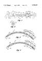
- FIG. 5shows in plan view a second embodiment of the present invention, having a malleable tip.
- FIG. 6shows a cross-section view of the tip of the embodiment of FIG. 5 along the line 6--6 of FIG. 5.
- FIG. 7shows in cross-section the end tip of the embodiment shown in FIG. 5 along line 7--7 of FIG. 5.
- the malleable introducer 11 of the inventionincludes a hollow, cylindrical tube 12 of malleable material, such as a ductile and medically approved malleable tubing, having an open proximal end 13 and an open distal end, or tip, 14.
- a hollow, cylindrically shaped sheath 15 of relatively thin materialhas a closed, soft, and rounded tip 16 and an end portion 17 securely attached and sealed to the outside cylindrical surface of tube 12 at position 18.
- a fluidtight sealexists between the inside of sheath 15 and the outside cylindrical surface of tube 12. Approximately one third of the length of sheath 15 may extend beyond the open distal end, or tip, 14 of tube 12. Approximately two thirds of the length of sheath 15 may overlay the distal end portion of tube 12, as shown.
- the diameter of sheath 15is somewhat larger than the outside diameter of tube 12.
- the length of tube 12is determined by the length of the catheter or endotracheal tube for which it is to be used.
- the diameter of tube 12, as well as the diameter of uninflated sheath 15,is less than the inside diameter of the catheter.
- the malleable tubehas relatively thick walls while maintaining an unobstructed channel for fluid flow therethrough. While allowing a significant amount of bending, the thick-walled and small-channeled malleable tube 12 demands less fluid for inflating the sheath 15. Additionally, the thick walls of the tube 12 prevents it from buckling during the bending or other configuration process.
- the hollow cylindrical tube 12is preferably constructed of a malleable metal that is chemically stable and readily made sterile.
- a malleable metalthat is chemically stable and readily made sterile.
- Such metalsinclude aluminum as aluminum spontaneously generates a noncorrosive and inert external layer of aluminum oxide. This aluminum oxide layer prevents any corrosion from taking place upon the hollow cylindrical tube 12.
- Other ductile, or malleable, metals, alloys, or materialsmay be used so long as they may be made sterile for use in the operating theater.
- a "dead soft" type of aluminumsuch as annealed 3003 aluminum (as it is known in the industry) is used.
- Some metalssuch as copper may require a coating of plastic about any exposed surface so as to prevent any reaction by the metal with its surrounding environment.
- a plastic coatingallows a metal such as copper to maintain a pristine state while providing an inert contact surface for any materials passing through or about the hollow cylindrical tube 12.
- copper or other materialsshould be so malleable as to be considered "dead soft.”
- Sheath 15may be composed of polyisoprene, latex rubber, polyvinyl chloride, or other suitable medically approved material. Sheath 15 is designed to be inflated by fluid supplied under pressure through hollow tube 12, as described hereinafter.
- inflation by fluid meansis intended to include any available or particularly advantageous, non-toxic fluid. While such fluids may include saline solutions, nitrogen or other inert gas or gas mixture, the use of such exotic fluids may be complicated and costly.
- the inflation fluidis air supplied ambient to the patient as it is readily available and adequate for surgical purposes.
- FIGS. 1, 3, 4, and 5illustrate a conventional spring-type hose or tube clamp 31 designed to slide along and around a hollow, pliable tube 20 coupled to the open proximal end 13 of tube 12 by coupler 19. Shown in its open position in FIGS. 1, 3, and 5, clamp 31 is closed by pressing the top leaf spring element 32 toward the bottom element 33, thereby squeezing tube 20 between the two jaws 34 and 35. Clamp 31 is held in its closed position by latch 36 when the tip 37 of leaf spring element 32 is forced to pass below latch 36. The flexible tube 20 is thereby closed and remains sealed until the latch 36 releases tip 37.
- the open proximal end 13 of tube 12may be provided with a manually controllable valve means, such as a stopcock (not shown).
- the stopcockmay have a hollow, open proximal end shaped as a connector fitting to receive a conventional medical syringe.
- the connector fittingmay be of the conventional "Luer" female type 21.
- the hollow, open distal end of the stopcockmay be tapered and fitted within the open proximal end 13 of tube 12.
- the stopcockmay include a vertical shaft extending perpendicularly through the valve between its open proximal and distal ends.
- the vertical shaftmay be attached to a handle to enable the vertical shaft to be rotated about a vertical axis.
- the stopcockwould generally be in its open position when the handle is aligned with the introducer 11.
- valve of the "one-way" typemay also be used, having a tapered, hollow, open proximal end; a tapered, open distal end; and an internal, resilient plunger or ball that normally closes the passage between the open proximal and distal ends.
- the conventional medical syringe of the piston-and-cylinder typeis designed to attach to the open proximal end and press against the internal, resilient plunger to open the valve. Fluid under pressure from the syringe then passes through valve into hollow tube 12. Upon detachment of the syringe, the internal resilient plunger returns to its normally closed position, thereby sealing the passage between open proximal and distal ends and closing the end of tube 12.
- FIGS. 3 and 4illustrate the inflatable introducer 11 of the present invention installed within a cuffed catheter 41.
- Catheter 41includes an open proximal end 42 having an external connector 42a for better manageability and greater airflow. At the opposite end is a beveled, open distal end 43. Alternatively, the open distal end 43 may be square and blunt so as to provide a uniform shoulder for the tip 16 of inflatable sheath 15. Introducer 11 is placed within catheter 41 such that the closed, smooth and rounded tip 16 of sheath 15 protrudes beyond the open distal end 43. The open distal end or tip 14 of tube 12 remains inside the open distal end 43 of catheter 41, as shown. To aid the placement of the closed, smooth and rounded tip 16 in the correct position, the rounded tip 16 may be marked by a band (not shown) to be aligned with the distal end 43 of catheter 41.
- Endotracheal catheter tube 41includes a thin, cylindrical cuff 44 affixed to the outer cylindrical portion of tube 41 near its open distal end 43.
- the interior of cuff 44is coupled to a small, flexible pilot tube 45, a portion of which is embedded within the wall of endotracheal tube 41, and through a conventional pilot balloon 46 to an inflation valve connector 47.
- Cylindrical sheath 15is in its noninflated condition when inserted into and through catheter 41. Approximately two thirds of its upper length may remain inside the distal end portion of catheter 41, as shown.
- the assembly of catheter, inflatable introducer with sheath, and fluid flow control means, as shown in FIG. 3,is in condition for inflation of sheath 15.
- FIGS. 3 and 4have been presented in an "upside-down” or “flipped-over” form.
- endotracheal tubesare inserted into the patient with the distal end 43 of the catheter pointing in an upwardly direction.
- the physicianmay then intubate the patient with catheter 41.
- FIG. 4illustrates the inflatable introducer 11 installed in a cuffed catheter 41 and in its inflated condition. Closed, smooth, and rounded tip 16 of sheath 15, protruding beyond the open, distal end 43, is inflated to a diameter equal to or slightly larger than the outer diameter of catheter 41, as shown.
- the beveled distal end, or tip, 43provides a surface against which inflated tip 16 of sheath 15 may bear as catheter 41 is intubated.
- Approximately two thirds of the length of sheath 15 situated within the distal end portion of catheter 41is also inflated to embrace and contact the inner cylindrical wall portion of the distal end of catheter 41.
- the physical contact between the expanded two-thirds portion of sheath 15 with the inner cylindrical wall of catheter 41anchors and holds inflatable sheath 15 against any sliding or twisting movement as catheter 41 is intubated.
- Distal tip 14 of hollow tube 12remains inside the distal end of catheter 43 in the inflated condition of sheath 15 as a precaution against any likelihood of rupture of sheath 15 by distal tip 14.
- Clamp 31, coupled to the proximal end 13 of tube 12,is shown in its closed position, is thereby closing and sealing tube 12.
- Sheath 15is thereby maintained in its inflated condition as catheter 41 with closed, smooth and rounded tip 16 is intubated into the passageway of a patient.
- clamp 31is opened to release fluid pressure within tube 12 and sheath 13. Introducer 11 is then withdrawn from catheter 41.
- Clamp 31coupled to the open proximal end 13 of tube 12, is in the open position, as shown in FIG. 3.
- tube 12is open and the assembled appliance may be packaged and sealed in an envelope to be sterilized by the conventional ethylene oxide process of gas sterilization or by any other medically acceptable radiation process.
- the inventionprovides an improved procedure for the intubation of catheters and endotracheal tubes by providing a smooth, soft, rounded and pliable guiding tip for entering and enlarging the passageway to be intubated.
- This pliable guiding tipis made more accessible and controllable by the addition of malleable, shape-retaining tubing. Damage and trauma to the patient are reduced and better, more controllable intubation is achieved.
- the inflatable sheath 15 of the introducer 11is readily inflated after rupturing the seals of the sterilized package while the catheter 41 and introducer 11 remain completely inside the package.
- the manually controllable clamp 31is available for easy access to the physician to facilitate inflation and closure.
- the smooth, soft and rounded tip 16may be lubricated, by the physician, along with the outer cylindrical surface of the catheter 41, and the appliance is prepared for intubation.
- the clamp 31is opened to release fluid pressure and deflate the sheath 15. The introducer with sheath is then withdrawn and discarded.
- an exemplary introducer 11could be constructed as follows. Beginning with a length of dead-soft 3003 aluminum tubing, the tubing is annealed, chamfered, and straight with no burrs or sharp edges.
- the inner diametermay be approximately 0.019 inches plus or minus 0.002 inches.
- the outer diametermay be 0.047 inches plus or minus 0.002 inches.
- the length of the tubemay be 12.0 inches plus or minus 0.12 inches. After such a dead-soft aluminum tube has been obtained, the entire length may be wiped with methyl ethyl ketone. The sheath and coupler may then be connected by adhesives to the tube 12.
- Clamp 31 and pliable tube 20 with connector fitting 21may then be affixed to the coupler 19 and, as appropriate, with adhesive.
- the hollow tube 12may be made of the same annealed 3003 aluminum with the following inner dimensions with the same respective tolerances: inner diameter 0.075 inches; outer diameter 0.125 inches; and a length of 15.0 inches.
- a second embodiment of the present inventionincludes the use of a malleable hollow tube 60 adjacent the open distal end 14 of the introducer tube 12.
- Those structures in FIGS. 5-7 which are the same as those in FIGS. 1-4are designated by the same or similar reference numbers.
- the end of the hollow malleable tip 60 most proximal to the clamp 31is in fluidtight engagement with the introducer tube 12 and may be enveloped by it.
- the distal end 61 of the hollow malleable tip 60is surrounded by material tending not to have sharp edges so that the sheath surrounding the distal end 16 or sheath 15 of the introducer 11 is not punctured by coming into contact with any sharp edges.
- the hollow malleable tip 60may be inserted into the flexible introducer tube 12 such that the distal end 61 of the malleable tip 60 is several millimeters within the distal end 14 of the introducer tube 12. The sheath 15 then extends several millimeters beyond the distal end 14 of the introducer tube 12.
- the malleable metalmay be entirely encased in plastic both within and without while maintaining the hollow tubular and malleable features of this structure and metal.
- drops of glue 62may be used to secure the malleable tip 60 within the flexible introducer tube 12.
- the malleable tipmay be subject to surface treatment as by electroless nickel in order to inhibit corrosion and enhance adhesion.
- An exemplary malleable tip 60could be constructed as follows. Using dead-soft C12200 annealed or equivalent copper with an approximate tensile strength of 30 kPSI and an approximate yield of 11 kPSI as available from Copper Development Associates, all burrs and sharp edges are removed from the malleable tip.
- the length of the malleable tip 60is approximately 3.0 inches plus or minus 0.1 inches with possible inner or outer diameters of 0.028 inches and 0.071 inches, respectively, and with tolerances of plus or minus 0.002 inches.
- an inner diameter of 0.031 inches and an outer diameter of 0.081 inches plus or minus 0.002 inchesmay also be used advantageously.
- the embodiment of the present invention where the entire introducer tube 12 is malleableproceeds as follows. Initially, the introducer tube 12 is straight or conforms to the initial curvature of the catheter 41. From this geometry, if the introducer 11 has not previously been inserted into the catheter 41, the introducer 11 is easily inserted into the catheter 41 so that the tip 16 extends beyond the open distal end 43 of the catheter per the procedure set forth previously. Once the introducer 11 has been secured within the catheter 41 after inflation, the frictional engagement between the inflated sheath 15 and the catheter interior will hold the introducer 11 in place relative to the catheter 41 while the malleable introducer tube 12 is bent to the physician's preferred configuration.
- the physicianmay accomplish this by hand, bending the tube into almost any configuration so long as the bends are not too severe.
- the fluid flow through the hollow introducer tubeshould not be obstructed nor should any breach be created in the wall of the hollow introducer tube.
- the frictional engagement between introducer 11 and catheter 41is sufficient to keep the catheter and introducer from turning with respect to one another during the configuration process or intubation.
- the catheter 41is intubated into the patient.
- an anesthetizing or other appropriate type of lubricantsuch as Lubafax jelly
- passage of the catheter 41 into the patient's mouth or noseis made easier.
- the shape of the catheter 41, as dictated by the malleable introducer tube 12,can be such that the distal introducer end 16 tends to press against anatomical structures that serve to guide the introducer tip 16 into the patient without trauma and avoiding obstruction.
- the physicianmay gently bend the malleable introducer tube 12 against a stationary object such as the physician's hand or fingers or any anatomical structure of the patient that would not be traumatized by the force generated from the bending process.
- a stationary objectsuch as the physician's hand or fingers or any anatomical structure of the patient that would not be traumatized by the force generated from the bending process.
- the inflated introducer tip 16is obstructed during intubation, it may be possible to avoid the obstruction and proceed with intubation by slightly withdrawing the catheter-introducer pair and bending the malleable introducer tube 12 so that the tip 16 adopts a different attitude with respect to the obstruction. Due to the lubricated and curved nature of the inflated introducer tip 16, the inflated introducer tip 16 may then approach the obstruction and find clear passage past it or may be pushed to one side by the obstruction so that the catheter 41 may proceed past the obstruction.
- the physicianmay bend the malleable tip 60 to a preferred configuration prior to or after inflation of the introducer tip 16 and secure the introducer 11 by such inflation to the interior of the catheter. Bending the malleable tip 60 prior to insertion of the introducer 11 into the catheter 41 should be avoided as it may prevent easy passage of the malleable tip into the catheter. Once the catheter portion surrounding the malleable tip has adopted the configuration preferred by the physician, the catheter-introducer pair may then be inserted into the patient.
- the width of the wall surrounding the malleable portion of the present inventionis on the same order as that of its opening 14, 61 into the sheath 15.
- the similarities in the wall width and the opening diameterprovides the structural support necessary to allow the hollow tube 12 or tip 60 to resist deformation during intubation to provide support, yet malleably deforms in the physician's hands prior to or during intubation. Due to the relative similarities of the openings 14, 61 and their associated wall thicknesses, the hollow tube 12 and the malleable tip 60 resist buckling and kinking.
- the wall thickness of the hollow tube 12such an introducer is 0.014 inches.
- the hollow tube 12has a wall thickness of 0.025 inches. In both instances, the diameter of the opening 14 of the hollow tube 12 is on the order of the wall thickness.
- an inner diameter of 0.028 inches and an outer diameter of 0.071 inchesprovides a wall with a thickness of 0.022 inches.
- An inner diameter of 0.031 inches and an outer diameter of 0.081 inchesprovides a wall of thickness 0.025 inches. In both instances, the diameter of the opening 61 of the malleable tip 60 is on the order of the wall thickness.
Landscapes
- Health & Medical Sciences (AREA)
- Pulmonology (AREA)
- Emergency Medicine (AREA)
- Engineering & Computer Science (AREA)
- Anesthesiology (AREA)
- Biomedical Technology (AREA)
- Heart & Thoracic Surgery (AREA)
- Hematology (AREA)
- Life Sciences & Earth Sciences (AREA)
- Animal Behavior & Ethology (AREA)
- General Health & Medical Sciences (AREA)
- Public Health (AREA)
- Veterinary Medicine (AREA)
- Otolaryngology (AREA)
- Media Introduction/Drainage Providing Device (AREA)
Abstract
Description
Claims (17)
Priority Applications (1)
| Application Number | Priority Date | Filing Date | Title |
|---|---|---|---|
| US08/445,368US5749357A (en) | 1995-05-19 | 1995-05-19 | Malleable introducer |
Applications Claiming Priority (1)
| Application Number | Priority Date | Filing Date | Title |
|---|---|---|---|
| US08/445,368US5749357A (en) | 1995-05-19 | 1995-05-19 | Malleable introducer |
Publications (1)
| Publication Number | Publication Date |
|---|---|
| US5749357Atrue US5749357A (en) | 1998-05-12 |
Family
ID=23768637
Family Applications (1)
| Application Number | Title | Priority Date | Filing Date |
|---|---|---|---|
| US08/445,368Expired - LifetimeUS5749357A (en) | 1995-05-19 | 1995-05-19 | Malleable introducer |
Country Status (1)
| Country | Link |
|---|---|
| US (1) | US5749357A (en) |
Cited By (56)
| Publication number | Priority date | Publication date | Assignee | Title |
|---|---|---|---|---|
| US6286509B1 (en)* | 1998-09-05 | 2001-09-11 | Smiths Group Plc | Introducers and tube assemblies |
| US6378521B1 (en)* | 1996-11-28 | 2002-04-30 | Ideamed N.V. | Artificial airway device |
| US6415787B1 (en)* | 1997-01-06 | 2002-07-09 | Georges Boussignac | Device for changing respiratory probes in the trachea of a patient |
| US20020195103A1 (en)* | 2001-03-05 | 2002-12-26 | Government Of The United States, As Represented By The Secretary Of The Army | Intubation device and method |
| US20030083547A1 (en)* | 2000-10-30 | 2003-05-01 | Bruce Hamilton | Endoscopic sheath assemblies having longitudinal expansion inhibiting mechanisms |
| US20030198629A1 (en)* | 2001-07-27 | 2003-10-23 | Brown James H. | Ultra-stable composition comprising moringa oil and its derivatives and uses thereof |
| US20030220588A1 (en)* | 2001-06-15 | 2003-11-27 | Radi Medical Systems Ab | Electrically conductive guide wire |
| US20030236505A1 (en)* | 2000-07-21 | 2003-12-25 | Frank Bonadio | Cannula |
| US20050126564A1 (en)* | 2003-12-11 | 2005-06-16 | Alexandr Pekar | Atraumatic endotracheal tube introducer and atraumatic intubation methods |
| WO2005061034A1 (en)* | 2003-12-11 | 2005-07-07 | The Research Foundation Of State University Of New York | An atraumatic endotracheal tube introducer and atraumatic intubation methods |
| WO2005094926A1 (en)* | 2004-03-23 | 2005-10-13 | Cook Critical Care Incorporated | Percutaneous introducer balloon |
| US20050235996A1 (en)* | 2004-04-27 | 2005-10-27 | Hooser David Theron V | Clamping assembly for limiting the depth of insertion of a respiratory care treatment device |
| US20050240146A1 (en)* | 2004-04-27 | 2005-10-27 | Nash John E | Thrombectomy and soft debris removal device |
| US20060161044A1 (en)* | 2000-10-30 | 2006-07-20 | Katsumi Oneda | Inflatable member for an endoscope sheath |
| US20060207604A1 (en)* | 2003-06-06 | 2006-09-21 | Radlyn Llc | Intubation device and method of use |
| US20070250069A1 (en)* | 2006-04-19 | 2007-10-25 | Cook Incorporated | Delivery device for an endoluminal prosthesis |
| US20080017195A1 (en)* | 2006-07-19 | 2008-01-24 | Yoshida Douglas K | Extendable lighted intubation stylet |
| USD567367S1 (en) | 2007-03-14 | 2008-04-22 | Mongeon Douglas R | Stylet |
| US20080097499A1 (en)* | 2004-04-27 | 2008-04-24 | Nash John E | Thrombectomy and soft debris removal device |
| US20080230056A1 (en)* | 2007-03-23 | 2008-09-25 | Benje Boedeker | Intubation guide |
| US20080275391A1 (en)* | 2007-05-01 | 2008-11-06 | Cook Critical Care Incorporated | Loading dilator with transition baloon |
| US20080281156A1 (en)* | 2004-04-21 | 2008-11-13 | Acclarent, Inc. | Methods and Apparatus for Treating Disorders of the Ear Nose and Throat |
| US20090221959A1 (en)* | 2008-02-28 | 2009-09-03 | Cook Critical Care Incorporated | Elongated medical apparatus with inflatable tip |
| US20090229614A1 (en)* | 2005-03-19 | 2009-09-17 | Smiths Group Plc | Tracheostomy Tube Assemblies |
| US20090318897A1 (en)* | 2008-06-20 | 2009-12-24 | Cook Critical Care Incorporated | Gastrojejunal feeding assembly |
| US20100083957A1 (en)* | 2007-04-11 | 2010-04-08 | Davis John J | Atraumatic introducer for nasal endotracheal tubes and its method of use |
| US20100163050A1 (en)* | 2008-12-30 | 2010-07-01 | Cook Critical Care Incorporated | Self-centering tracheostomy tube |
| US20110054585A1 (en)* | 2005-12-23 | 2011-03-03 | Cook Incorporated | Prosthesis deployment system |
| US20130053830A1 (en)* | 2011-08-24 | 2013-02-28 | Gyrus Ent, L.L.C. | Surgical instrument with malleable tubing |
| US8932276B1 (en) | 2004-04-21 | 2015-01-13 | Acclarent, Inc. | Shapeable guide catheters and related methods |
| US20150258295A1 (en)* | 2011-10-04 | 2015-09-17 | Cobra Stylet Llc | Device for introducing an airway tube into the trachea |
| US9220879B2 (en) | 2004-04-21 | 2015-12-29 | Acclarent, Inc. | Devices, systems and methods useable for treating sinusitis |
| US9241834B2 (en) | 2004-04-21 | 2016-01-26 | Acclarent, Inc. | Devices, systems and methods for treating disorders of the ear, nose and throat |
| US9610428B2 (en) | 2004-04-21 | 2017-04-04 | Acclarent, Inc. | Devices, systems and methods useable for treating frontal sinusitis |
| US20170119952A1 (en)* | 2015-10-30 | 2017-05-04 | Medtronic Xomed, Inc. | Method and Apparatus for Irrigation |
| US9649477B2 (en) | 2004-04-21 | 2017-05-16 | Acclarent, Inc. | Frontal sinus spacer |
| US9826999B2 (en) | 2004-04-21 | 2017-11-28 | Acclarent, Inc. | Methods and apparatus for treating disorders of the ear nose and throat |
| US20180242833A1 (en)* | 2016-01-07 | 2018-08-30 | Glenn P. Gardner | Endotracheal tube insertion device |
| US10098652B2 (en) | 2004-04-21 | 2018-10-16 | Acclarent, Inc. | Systems and methods for transnasal dilation of passageways in the ear, nose or throat |
| US10118019B2 (en) | 2014-01-09 | 2018-11-06 | Hollister Incorporated | Catheter cartridge assemblies and methods of using the same for intermittent catheterization |
| US10124154B2 (en) | 2005-06-10 | 2018-11-13 | Acclarent, Inc. | Catheters with non-removable guide members useable for treatment of sinusitis |
| US10188413B1 (en) | 2004-04-21 | 2019-01-29 | Acclarent, Inc. | Deflectable guide catheters and related methods |
| US20190232007A1 (en)* | 2016-09-06 | 2019-08-01 | H. Lee Moffitt Cancer Center & Research Institute, Inc. | Endotracheal tube stylet |
| US20190254701A1 (en)* | 2013-04-26 | 2019-08-22 | Medtronic Xomed, Inc. | Medical Device And Its Construction |
| US10406322B2 (en) | 2014-01-09 | 2019-09-10 | Hollister Incorporated | Catheter assemblies having a protective lubricious sleeve |
| US10492810B2 (en) | 2004-04-21 | 2019-12-03 | Acclarent, Inc. | Devices, systems and methods for diagnosing and treating sinusitis and other disorders of the ears, nose and/or throat |
| US10631756B2 (en) | 2004-04-21 | 2020-04-28 | Acclarent, Inc. | Guidewires for performing image guided procedures |
| WO2020236588A1 (en)* | 2019-05-21 | 2020-11-26 | Bryan Medical, Inc. | Endotracheal tube |
| US10856727B2 (en) | 2004-04-21 | 2020-12-08 | Acclarent, Inc. | Endoscopic methods and devices for transnasal procedures |
| US10874838B2 (en) | 2004-04-21 | 2020-12-29 | Acclarent, Inc. | Systems and methods for transnasal dilation of passageways in the ear, nose or throat |
| US11065061B2 (en) | 2004-04-21 | 2021-07-20 | Acclarent, Inc. | Systems and methods for performing image guided procedures within the ear, nose, throat and paranasal sinuses |
| US20210322700A1 (en)* | 2020-04-16 | 2021-10-21 | University Of Florida Research Foundation, Inc. | Tube changer device and methods of use thereof |
| US11529502B2 (en) | 2004-04-21 | 2022-12-20 | Acclarent, Inc. | Apparatus and methods for dilating and modifying ostia of paranasal sinuses and other intranasal or paranasal structures |
| US11964094B2 (en) | 2015-10-30 | 2024-04-23 | Medtronic Xomed, Inc. | Method and apparatus for irrigation |
| US11980460B2 (en) | 2016-08-11 | 2024-05-14 | Medtronic Xomed, Inc. | System and method for motion detection and accounting |
| US12121658B2 (en) | 2019-05-15 | 2024-10-22 | Teleflex Life Sciences Unlimited Company | Tracheostomy dilator |
Citations (25)
| Publication number | Priority date | Publication date | Assignee | Title |
|---|---|---|---|---|
| US3957055A (en)* | 1974-09-23 | 1976-05-18 | Linder Gerald S | Catheter guide |
| US3996939A (en)* | 1975-07-22 | 1976-12-14 | National Catheter Corporation | Intubation stylets |
| US4185639A (en)* | 1978-03-27 | 1980-01-29 | Linder Gerald S | Adjustable stop for endotracheal tube guide |
| US4261339A (en)* | 1978-03-06 | 1981-04-14 | Datascope Corp. | Balloon catheter with rotatable support |
| US4351330A (en)* | 1978-01-30 | 1982-09-28 | Scarberry Eugene N | Emergency internal defibrillation |
| US4471779A (en)* | 1976-08-25 | 1984-09-18 | Becton, Dickinson And Company | Miniature balloon catheter |
| US4655214A (en)* | 1984-06-28 | 1987-04-07 | Linder Gerald S | Inflatable introducer for aiding the intubation of catheters and endotracheal tubes |
| US4716896A (en)* | 1986-08-01 | 1988-01-05 | Ackrad Laboratories | Bronchial catheter |
| US4819619A (en)* | 1987-01-16 | 1989-04-11 | Augustine Scott D | Device for inserting a nasal tube |
| US4865586A (en)* | 1987-09-21 | 1989-09-12 | Martha Hedberg | Suction stylet for endotracheal intubation |
| US4913139A (en)* | 1989-02-09 | 1990-04-03 | Ballew Donald H | Method of translaryngeal retrograde tracheal intubation |
| US4938746A (en)* | 1988-03-25 | 1990-07-03 | The Kendall Company | Novel nasogastric device |
| US5038766A (en)* | 1989-11-08 | 1991-08-13 | Parker Jeffrey D | Blind orolaryngeal and oroesophageal guiding and aiming device |
| US5108366A (en)* | 1990-09-28 | 1992-04-28 | Ovamed Corporation | Delivery catheter |
| US5108374A (en)* | 1990-05-02 | 1992-04-28 | Critikon, Inc. | Stickless catheter with manual shut-off valve |
| US5127905A (en)* | 1990-05-02 | 1992-07-07 | Critikon, Inc. | Stickless catheter with manual shut-off valve |
| US5179963A (en)* | 1991-10-11 | 1993-01-19 | Berger J Lee | Percutaneous carpal tunnel plasty method |
| US5235970A (en)* | 1990-03-26 | 1993-08-17 | Augustine Medical, Inc. | Tracheal intubation with a stylet guide |
| US5242429A (en)* | 1992-05-14 | 1993-09-07 | Nwaneri Ngozika J | Enteral feeding tube with guide wire |
| US5257620A (en)* | 1991-12-12 | 1993-11-02 | Schermerhorn Jeffrey W | Apparatus and method for endotracheal intubation |
| US5273527A (en)* | 1992-05-12 | 1993-12-28 | Ovamed Corporation | Delivery catheter |
| US5295493A (en)* | 1992-03-19 | 1994-03-22 | Interventional Technologies, Inc. | Anatomical guide wire |
| US5329921A (en)* | 1993-03-01 | 1994-07-19 | Spiro Socaris | Endotracheal tube |
| US5339805A (en)* | 1989-11-08 | 1994-08-23 | Parker Jeffrey D | Blind orolaryngeal and oroesophageal guiding and aiming device |
| US5341803A (en)* | 1993-06-22 | 1994-08-30 | Goldberg Michael S | Apparatus and method for monitoring gastric fluid pH |
- 1995
- 1995-05-19USUS08/445,368patent/US5749357A/ennot_activeExpired - Lifetime
Patent Citations (26)
| Publication number | Priority date | Publication date | Assignee | Title |
|---|---|---|---|---|
| US3957055A (en)* | 1974-09-23 | 1976-05-18 | Linder Gerald S | Catheter guide |
| US3996939A (en)* | 1975-07-22 | 1976-12-14 | National Catheter Corporation | Intubation stylets |
| US4471779A (en)* | 1976-08-25 | 1984-09-18 | Becton, Dickinson And Company | Miniature balloon catheter |
| US4351330A (en)* | 1978-01-30 | 1982-09-28 | Scarberry Eugene N | Emergency internal defibrillation |
| US4261339B1 (en)* | 1978-03-06 | 1990-09-25 | Datascope Corp | |
| US4261339A (en)* | 1978-03-06 | 1981-04-14 | Datascope Corp. | Balloon catheter with rotatable support |
| US4185639A (en)* | 1978-03-27 | 1980-01-29 | Linder Gerald S | Adjustable stop for endotracheal tube guide |
| US4655214A (en)* | 1984-06-28 | 1987-04-07 | Linder Gerald S | Inflatable introducer for aiding the intubation of catheters and endotracheal tubes |
| US4716896A (en)* | 1986-08-01 | 1988-01-05 | Ackrad Laboratories | Bronchial catheter |
| US4819619A (en)* | 1987-01-16 | 1989-04-11 | Augustine Scott D | Device for inserting a nasal tube |
| US4865586A (en)* | 1987-09-21 | 1989-09-12 | Martha Hedberg | Suction stylet for endotracheal intubation |
| US4938746A (en)* | 1988-03-25 | 1990-07-03 | The Kendall Company | Novel nasogastric device |
| US4913139A (en)* | 1989-02-09 | 1990-04-03 | Ballew Donald H | Method of translaryngeal retrograde tracheal intubation |
| US5038766A (en)* | 1989-11-08 | 1991-08-13 | Parker Jeffrey D | Blind orolaryngeal and oroesophageal guiding and aiming device |
| US5339805A (en)* | 1989-11-08 | 1994-08-23 | Parker Jeffrey D | Blind orolaryngeal and oroesophageal guiding and aiming device |
| US5235970A (en)* | 1990-03-26 | 1993-08-17 | Augustine Medical, Inc. | Tracheal intubation with a stylet guide |
| US5127905A (en)* | 1990-05-02 | 1992-07-07 | Critikon, Inc. | Stickless catheter with manual shut-off valve |
| US5108374A (en)* | 1990-05-02 | 1992-04-28 | Critikon, Inc. | Stickless catheter with manual shut-off valve |
| US5108366A (en)* | 1990-09-28 | 1992-04-28 | Ovamed Corporation | Delivery catheter |
| US5179963A (en)* | 1991-10-11 | 1993-01-19 | Berger J Lee | Percutaneous carpal tunnel plasty method |
| US5257620A (en)* | 1991-12-12 | 1993-11-02 | Schermerhorn Jeffrey W | Apparatus and method for endotracheal intubation |
| US5295493A (en)* | 1992-03-19 | 1994-03-22 | Interventional Technologies, Inc. | Anatomical guide wire |
| US5273527A (en)* | 1992-05-12 | 1993-12-28 | Ovamed Corporation | Delivery catheter |
| US5242429A (en)* | 1992-05-14 | 1993-09-07 | Nwaneri Ngozika J | Enteral feeding tube with guide wire |
| US5329921A (en)* | 1993-03-01 | 1994-07-19 | Spiro Socaris | Endotracheal tube |
| US5341803A (en)* | 1993-06-22 | 1994-08-30 | Goldberg Michael S | Apparatus and method for monitoring gastric fluid pH |
Non-Patent Citations (2)
| Title |
|---|
| Seiji Watanabe, M.D., Ph.D., et al; Anesth Analg 1994;78; A "Bubble-Tip" (Airguide®) Tracheal Tube System: Its Effects on Incidence of Epistaxis and Ease of Tube Advancement in the Subglottic Region During Nasotracheal Intubation; Feb. 18, 1994; pp. 1140-1143. |
| Seiji Watanabe, M.D., Ph.D., et al; Anesth Analg 1994;78; A Bubble Tip (Airguide ) Tracheal Tube System: Its Effects on Incidence of Epistaxis and Ease of Tube Advancement in the Subglottic Region During Nasotracheal Intubation; Feb. 18, 1994; pp. 1140 1143.* |
Cited By (110)
| Publication number | Priority date | Publication date | Assignee | Title |
|---|---|---|---|---|
| US6378521B1 (en)* | 1996-11-28 | 2002-04-30 | Ideamed N.V. | Artificial airway device |
| US6415787B1 (en)* | 1997-01-06 | 2002-07-09 | Georges Boussignac | Device for changing respiratory probes in the trachea of a patient |
| US6286509B1 (en)* | 1998-09-05 | 2001-09-11 | Smiths Group Plc | Introducers and tube assemblies |
| US20030236505A1 (en)* | 2000-07-21 | 2003-12-25 | Frank Bonadio | Cannula |
| US8845518B2 (en) | 2000-10-30 | 2014-09-30 | Vision Sciences, Inc. | Inflatable member for an endoscope sheath |
| US20030083547A1 (en)* | 2000-10-30 | 2003-05-01 | Bruce Hamilton | Endoscopic sheath assemblies having longitudinal expansion inhibiting mechanisms |
| US20060161044A1 (en)* | 2000-10-30 | 2006-07-20 | Katsumi Oneda | Inflatable member for an endoscope sheath |
| US6793661B2 (en)* | 2000-10-30 | 2004-09-21 | Vision Sciences, Inc. | Endoscopic sheath assemblies having longitudinal expansion inhibiting mechanisms |
| US20100059048A1 (en)* | 2001-03-05 | 2010-03-11 | Government Of The United States As Represented By The Secretary Of The Army | Intubation device and method |
| WO2002070038A3 (en)* | 2001-03-05 | 2003-05-22 | Sean T O'mara | Intubation device and method |
| US20020195103A1 (en)* | 2001-03-05 | 2002-12-26 | Government Of The United States, As Represented By The Secretary Of The Army | Intubation device and method |
| US7552729B2 (en) | 2001-03-05 | 2009-06-30 | The United States Of America As Represented By The Secretary Of The Army | Intubation device and method |
| US20030220588A1 (en)* | 2001-06-15 | 2003-11-27 | Radi Medical Systems Ab | Electrically conductive guide wire |
| US8579825B2 (en)* | 2001-06-15 | 2013-11-12 | Radi Medical Systems Ab | Electrically conductive guide wire |
| US7691397B2 (en) | 2001-07-27 | 2010-04-06 | International Flora Technologies, Ltd. | Ultra-stable composition comprising Moringa oil and its derivatives and uses thereof |
| US20030198629A1 (en)* | 2001-07-27 | 2003-10-23 | Brown James H. | Ultra-stable composition comprising moringa oil and its derivatives and uses thereof |
| WO2004052426A3 (en)* | 2002-12-05 | 2004-08-05 | Vision Sciences Inc | Endoscopic sheath assemblies having longitudinal expansion inhibiting mechanisms |
| US20060207604A1 (en)* | 2003-06-06 | 2006-09-21 | Radlyn Llc | Intubation device and method of use |
| US20050126564A1 (en)* | 2003-12-11 | 2005-06-16 | Alexandr Pekar | Atraumatic endotracheal tube introducer and atraumatic intubation methods |
| WO2005061034A1 (en)* | 2003-12-11 | 2005-07-07 | The Research Foundation Of State University Of New York | An atraumatic endotracheal tube introducer and atraumatic intubation methods |
| US6978784B2 (en)* | 2003-12-11 | 2005-12-27 | The Research Foundation State University Of New York | Atraumatic endotracheal tube introducer and atraumatic intubation methods |
| WO2005094926A1 (en)* | 2004-03-23 | 2005-10-13 | Cook Critical Care Incorporated | Percutaneous introducer balloon |
| US20060081260A1 (en)* | 2004-03-23 | 2006-04-20 | Eells Scott E | Percutaneous introducer balloon |
| US10492810B2 (en) | 2004-04-21 | 2019-12-03 | Acclarent, Inc. | Devices, systems and methods for diagnosing and treating sinusitis and other disorders of the ears, nose and/or throat |
| US9220879B2 (en) | 2004-04-21 | 2015-12-29 | Acclarent, Inc. | Devices, systems and methods useable for treating sinusitis |
| US9814379B2 (en) | 2004-04-21 | 2017-11-14 | Acclarent, Inc. | Methods and apparatus for treating disorders of the ear nose and throat |
| US11957318B2 (en) | 2004-04-21 | 2024-04-16 | Acclarent, Inc. | Methods and apparatus for treating disorders of the ear nose and throat |
| US11864725B2 (en) | 2004-04-21 | 2024-01-09 | Acclarent, Inc. | Devices, systems and methods for diagnosing and treating sinusitis and other disorders of the ears, nose and/or throat |
| US20080281156A1 (en)* | 2004-04-21 | 2008-11-13 | Acclarent, Inc. | Methods and Apparatus for Treating Disorders of the Ear Nose and Throat |
| US9649477B2 (en) | 2004-04-21 | 2017-05-16 | Acclarent, Inc. | Frontal sinus spacer |
| US11589742B2 (en) | 2004-04-21 | 2023-02-28 | Acclarent, Inc. | Methods and apparatus for treating disorders of the ear nose and throat |
| US11529502B2 (en) | 2004-04-21 | 2022-12-20 | Acclarent, Inc. | Apparatus and methods for dilating and modifying ostia of paranasal sinuses and other intranasal or paranasal structures |
| US11511090B2 (en) | 2004-04-21 | 2022-11-29 | Acclarent, Inc. | Devices, systems and methods useable for treating sinusitis |
| US9826999B2 (en) | 2004-04-21 | 2017-11-28 | Acclarent, Inc. | Methods and apparatus for treating disorders of the ear nose and throat |
| US11202644B2 (en) | 2004-04-21 | 2021-12-21 | Acclarent, Inc. | Shapeable guide catheters and related methods |
| US9610428B2 (en) | 2004-04-21 | 2017-04-04 | Acclarent, Inc. | Devices, systems and methods useable for treating frontal sinusitis |
| US11065061B2 (en) | 2004-04-21 | 2021-07-20 | Acclarent, Inc. | Systems and methods for performing image guided procedures within the ear, nose, throat and paranasal sinuses |
| US10034682B2 (en) | 2004-04-21 | 2018-07-31 | Acclarent, Inc. | Devices, systems and methods useable for treating frontal sinusitis |
| US11020136B2 (en) | 2004-04-21 | 2021-06-01 | Acclarent, Inc. | Deflectable guide catheters and related methods |
| US11019989B2 (en) | 2004-04-21 | 2021-06-01 | Acclarent, Inc. | Methods and apparatus for treating disorders of the ear nose and throat |
| US10098652B2 (en) | 2004-04-21 | 2018-10-16 | Acclarent, Inc. | Systems and methods for transnasal dilation of passageways in the ear, nose or throat |
| US9370649B2 (en) | 2004-04-21 | 2016-06-21 | Acclarent, Inc. | Devices, systems and methods useable for treating sinusitis |
| US10874838B2 (en) | 2004-04-21 | 2020-12-29 | Acclarent, Inc. | Systems and methods for transnasal dilation of passageways in the ear, nose or throat |
| US10856727B2 (en) | 2004-04-21 | 2020-12-08 | Acclarent, Inc. | Endoscopic methods and devices for transnasal procedures |
| US10806477B2 (en) | 2004-04-21 | 2020-10-20 | Acclarent, Inc. | Systems and methods for transnasal dilation of passageways in the ear, nose or throat |
| US10779752B2 (en) | 2004-04-21 | 2020-09-22 | Acclarent, Inc. | Guidewires for performing image guided procedures |
| US10702295B2 (en) | 2004-04-21 | 2020-07-07 | Acclarent, Inc. | Methods and apparatus for treating disorders of the ear nose and throat |
| US10695080B2 (en) | 2004-04-21 | 2020-06-30 | Acclarent, Inc. | Devices, systems and methods for diagnosing and treating sinusitis and other disorders of the ears, nose and/or throat |
| US10631756B2 (en) | 2004-04-21 | 2020-04-28 | Acclarent, Inc. | Guidewires for performing image guided procedures |
| US10188413B1 (en) | 2004-04-21 | 2019-01-29 | Acclarent, Inc. | Deflectable guide catheters and related methods |
| US10441758B2 (en) | 2004-04-21 | 2019-10-15 | Acclarent, Inc. | Frontal sinus spacer |
| US9241834B2 (en) | 2004-04-21 | 2016-01-26 | Acclarent, Inc. | Devices, systems and methods for treating disorders of the ear, nose and throat |
| US8932276B1 (en) | 2004-04-21 | 2015-01-13 | Acclarent, Inc. | Shapeable guide catheters and related methods |
| US8961398B2 (en) | 2004-04-21 | 2015-02-24 | Acclarent, Inc. | Methods and apparatus for treating disorders of the ear, nose and throat |
| US10500380B2 (en) | 2004-04-21 | 2019-12-10 | Acclarent, Inc. | Devices, systems and methods useable for treating sinusitis |
| US9167961B2 (en) | 2004-04-21 | 2015-10-27 | Acclarent, Inc. | Methods and apparatus for treating disorders of the ear nose and throat |
| US20050235996A1 (en)* | 2004-04-27 | 2005-10-27 | Hooser David Theron V | Clamping assembly for limiting the depth of insertion of a respiratory care treatment device |
| US9808277B2 (en) | 2004-04-27 | 2017-11-07 | The Spectranetics Corporation | Thrombectomy and soft debris removal device |
| US8920402B2 (en) | 2004-04-27 | 2014-12-30 | The Spectranetics Corporation | Thrombectomy and soft debris removal device |
| US20050240146A1 (en)* | 2004-04-27 | 2005-10-27 | Nash John E | Thrombectomy and soft debris removal device |
| US10517633B2 (en) | 2004-04-27 | 2019-12-31 | The Spectranetics Corporation | Thrombectomy and soft debris removal device |
| US7976528B2 (en) | 2004-04-27 | 2011-07-12 | The Spectranetics, Corp. | Thrombectomy and soft debris removal device |
| US7959608B2 (en)* | 2004-04-27 | 2011-06-14 | The Spectranetics Corporation | Thrombectomy and soft debris removal device |
| US20100145259A1 (en)* | 2004-04-27 | 2010-06-10 | The Spectranetics Corporation | Thrombectomy and soft debris removal device |
| US20070282303A1 (en)* | 2004-04-27 | 2007-12-06 | Nash John E | Thrombectomy and soft debris removal device |
| US7666161B2 (en)* | 2004-04-27 | 2010-02-23 | The Spectranetics Corporation | Thrombectomy and soft debris removal device |
| US7353822B2 (en) | 2004-04-27 | 2008-04-08 | Kimberly-Clark , Worldwide, Inc. | Clamping assembly for limiting the depth of insertion of a respiratory care treatment device |
| US20080097499A1 (en)* | 2004-04-27 | 2008-04-24 | Nash John E | Thrombectomy and soft debris removal device |
| US9750911B2 (en)* | 2005-03-19 | 2017-09-05 | Smiths Group Plc | Tracheostomy tube assemblies |
| US20090229614A1 (en)* | 2005-03-19 | 2009-09-17 | Smiths Group Plc | Tracheostomy Tube Assemblies |
| US10124154B2 (en) | 2005-06-10 | 2018-11-13 | Acclarent, Inc. | Catheters with non-removable guide members useable for treatment of sinusitis |
| US10842978B2 (en) | 2005-06-10 | 2020-11-24 | Acclarent, Inc. | Catheters with non-removable guide members useable for treatment of sinusitis |
| US20110054585A1 (en)* | 2005-12-23 | 2011-03-03 | Cook Incorporated | Prosthesis deployment system |
| US8709060B2 (en) | 2005-12-23 | 2014-04-29 | Cook Medical Technologies Llc | Prosthesis deployment system |
| US20070250069A1 (en)* | 2006-04-19 | 2007-10-25 | Cook Incorporated | Delivery device for an endoluminal prosthesis |
| US9308105B2 (en) | 2006-04-19 | 2016-04-12 | Cook Medical Technologies Llc | Delivery device for an endoluminal prosthesis |
| US20080017195A1 (en)* | 2006-07-19 | 2008-01-24 | Yoshida Douglas K | Extendable lighted intubation stylet |
| US8746239B2 (en)* | 2006-07-19 | 2014-06-10 | Douglas K. Yoshida | Extendable lighted intubation stylet |
| USD567367S1 (en) | 2007-03-14 | 2008-04-22 | Mongeon Douglas R | Stylet |
| US20080230056A1 (en)* | 2007-03-23 | 2008-09-25 | Benje Boedeker | Intubation guide |
| US8561605B2 (en) | 2007-04-11 | 2013-10-22 | John J. Davis | Atraumatic introducer for nasal endotracheal tubes and its method of use |
| US20100083957A1 (en)* | 2007-04-11 | 2010-04-08 | Davis John J | Atraumatic introducer for nasal endotracheal tubes and its method of use |
| US20080275391A1 (en)* | 2007-05-01 | 2008-11-06 | Cook Critical Care Incorporated | Loading dilator with transition baloon |
| US8424534B2 (en) | 2007-05-01 | 2013-04-23 | Cook Medical Technologies Llc | Loading dilator with transition balloon |
| US8012122B2 (en) | 2008-02-28 | 2011-09-06 | Cook Medical Technologies Llc | Elongated medical apparatus with inflatable tip |
| US20090221959A1 (en)* | 2008-02-28 | 2009-09-03 | Cook Critical Care Incorporated | Elongated medical apparatus with inflatable tip |
| US20090318897A1 (en)* | 2008-06-20 | 2009-12-24 | Cook Critical Care Incorporated | Gastrojejunal feeding assembly |
| US20100163050A1 (en)* | 2008-12-30 | 2010-07-01 | Cook Critical Care Incorporated | Self-centering tracheostomy tube |
| US9265907B2 (en) | 2008-12-30 | 2016-02-23 | Cook Medical Technologies Llc | Self-centering tracheostomy tube |
| CN103826554A (en)* | 2011-08-24 | 2014-05-28 | 吉鲁斯恩特公司 | Surgical instrument with malleable tubing |
| US20130053830A1 (en)* | 2011-08-24 | 2013-02-28 | Gyrus Ent, L.L.C. | Surgical instrument with malleable tubing |
| US9198685B2 (en)* | 2011-08-24 | 2015-12-01 | Gyrus Ent, L.L.C. | Surgical instrument with malleable tubing |
| US9381032B2 (en) | 2011-08-24 | 2016-07-05 | Gyrus Ent, L.L.C. | Surgical instrument with malleable tubing |
| US9579476B2 (en)* | 2011-10-04 | 2017-02-28 | Cobra Stylet Llc | Device for introducing an airway tube into the trachea |
| US20150258295A1 (en)* | 2011-10-04 | 2015-09-17 | Cobra Stylet Llc | Device for introducing an airway tube into the trachea |
| US20190254701A1 (en)* | 2013-04-26 | 2019-08-22 | Medtronic Xomed, Inc. | Medical Device And Its Construction |
| US11883063B2 (en)* | 2013-04-26 | 2024-01-30 | Medtronic Xomed, Inc. | Medical device and its construction |
| US10118019B2 (en) | 2014-01-09 | 2018-11-06 | Hollister Incorporated | Catheter cartridge assemblies and methods of using the same for intermittent catheterization |
| US10406322B2 (en) | 2014-01-09 | 2019-09-10 | Hollister Incorporated | Catheter assemblies having a protective lubricious sleeve |
| US11266776B2 (en)* | 2015-10-30 | 2022-03-08 | Medtronic Xomed, Inc. | Method and apparatus for irrigation |
| US20170119952A1 (en)* | 2015-10-30 | 2017-05-04 | Medtronic Xomed, Inc. | Method and Apparatus for Irrigation |
| US11964094B2 (en) | 2015-10-30 | 2024-04-23 | Medtronic Xomed, Inc. | Method and apparatus for irrigation |
| US10335023B2 (en)* | 2016-01-07 | 2019-07-02 | Glenn P. Gardner | Endotracheal tube insertion device |
| US20180242833A1 (en)* | 2016-01-07 | 2018-08-30 | Glenn P. Gardner | Endotracheal tube insertion device |
| US11980460B2 (en) | 2016-08-11 | 2024-05-14 | Medtronic Xomed, Inc. | System and method for motion detection and accounting |
| US20190232007A1 (en)* | 2016-09-06 | 2019-08-01 | H. Lee Moffitt Cancer Center & Research Institute, Inc. | Endotracheal tube stylet |
| US12121658B2 (en) | 2019-05-15 | 2024-10-22 | Teleflex Life Sciences Unlimited Company | Tracheostomy dilator |
| WO2020236588A1 (en)* | 2019-05-21 | 2020-11-26 | Bryan Medical, Inc. | Endotracheal tube |
| US11628264B2 (en) | 2019-05-21 | 2023-04-18 | Bryan Medical Inc. | Endotracheal tube with resistant material, sleeve and cuff |
| US20210322700A1 (en)* | 2020-04-16 | 2021-10-21 | University Of Florida Research Foundation, Inc. | Tube changer device and methods of use thereof |
Similar Documents
| Publication | Publication Date | Title |
|---|---|---|
| US5749357A (en) | Malleable introducer | |
| US4655214A (en) | Inflatable introducer for aiding the intubation of catheters and endotracheal tubes | |
| US5277178A (en) | Medico-surgical device | |
| US4329983A (en) | Guide device for endotracheal tubes | |
| US4498473A (en) | Variable stiffness tracheal tube | |
| CA1183654A (en) | Voice button prosthesis and method for installing same | |
| JP3924033B2 (en) | Device for forming a hole in the tracheal wall | |
| US4649913A (en) | Tracheostomy tube assemblies | |
| US3460541A (en) | Endotracheal intubation tubes | |
| US4150676A (en) | Endotracheal tubes with intubation direction control means | |
| US5259377A (en) | Endotracheal tube stylet | |
| US4364391A (en) | Tracheostomy apparatus and method | |
| US5694929A (en) | Method and apparatus for ventilation/oxygenation during guided insertion of an endotracheal tube | |
| US4589410A (en) | Endotracheal tube | |
| AU723873B2 (en) | Laryngeal mask assemblies | |
| US4351330A (en) | Emergency internal defibrillation | |
| US20060207604A1 (en) | Intubation device and method of use | |
| EP1744803A2 (en) | Imaging catheter | |
| JP2006527027A (en) | Intubation device | |
| US20120073572A1 (en) | Intubation Stylet & Endotracheal Tube | |
| CN113144361B (en) | Two-way intubate tracheotomy expansion device with intubate passageway | |
| KR102040815B1 (en) | Tube for trachea intubation | |
| EP0371752A1 (en) | Tracheostomy tube assemblies | |
| WO1998019728A1 (en) | Malleable introducer | |
| CN102018549A (en) | Percutaneous tracheotomy device |
Legal Events
| Date | Code | Title | Description |
|---|---|---|---|
| STCF | Information on status: patent grant | Free format text:PATENTED CASE | |
| FEPP | Fee payment procedure | Free format text:PAT HLDR NO LONGER CLAIMS SMALL ENT STAT AS INDIV INVENTOR (ORIGINAL EVENT CODE: LSM1); ENTITY STATUS OF PATENT OWNER: LARGE ENTITY | |
| REFU | Refund | Free format text:REFUND - PAYMENT OF MAINTENANCE FEE, 4TH YR, SMALL ENTITY (ORIGINAL EVENT CODE: R283); ENTITY STATUS OF PATENT OWNER: LARGE ENTITY | |
| FPAY | Fee payment | Year of fee payment:4 | |
| AS | Assignment | Owner name:TECHNOLOGY HOLDING COMPANY II, DELAWARE Free format text:ASSIGNMENT OF ASSIGNORS INTEREST;ASSIGNOR:INMED CORPORATION;REEL/FRAME:013392/0688 Effective date:20020927 | |
| FPAY | Fee payment | Year of fee payment:8 | |
| FEPP | Fee payment procedure | Free format text:PAYOR NUMBER ASSIGNED (ORIGINAL EVENT CODE: ASPN); ENTITY STATUS OF PATENT OWNER: LARGE ENTITY Free format text:PAYER NUMBER DE-ASSIGNED (ORIGINAL EVENT CODE: RMPN); ENTITY STATUS OF PATENT OWNER: LARGE ENTITY | |
| REMI | Maintenance fee reminder mailed | ||
| FPAY | Fee payment | Year of fee payment:12 | |
| SULP | Surcharge for late payment | Year of fee payment:11 |