US5749028A - Multi-size photoreceptor flange bearing - Google Patents
Multi-size photoreceptor flange bearingDownload PDFInfo
- Publication number
- US5749028A US5749028AUS08/672,344US67234496AUS5749028AUS 5749028 AUS5749028 AUS 5749028AUS 67234496 AUS67234496 AUS 67234496AUS 5749028 AUS5749028 AUS 5749028A
- Authority
- US
- United States
- Prior art keywords
- bearing
- shaft
- bore
- sleeve
- printing machine
- Prior art date
- Legal status (The legal status is an assumption and is not a legal conclusion. Google has not performed a legal analysis and makes no representation as to the accuracy of the status listed.)
- Expired - Fee Related
Links
- 108091008695photoreceptorsProteins0.000titledescription29
- 239000000463materialSubstances0.000claimsdescription27
- 230000001050lubricating effectEffects0.000claimsdescription9
- 229910000906BronzeInorganic materials0.000claimsdescription6
- OKTJSMMVPCPJKN-UHFFFAOYSA-NCarbonChemical compound[C]OKTJSMMVPCPJKN-UHFFFAOYSA-N0.000claimsdescription6
- 239000010974bronzeSubstances0.000claimsdescription6
- 229910052799carbonInorganic materials0.000claimsdescription6
- KUNSUQLRTQLHQQ-UHFFFAOYSA-Ncopper tinChemical compound[Cu].[Sn]KUNSUQLRTQLHQQ-UHFFFAOYSA-N0.000claimsdescription6
- 238000012545processingMethods0.000claimsdescription3
- 239000004020conductorSubstances0.000claims6
- 239000000758substrateSubstances0.000description8
- 239000000843powderSubstances0.000description7
- 238000012546transferMethods0.000description6
- 239000004033plasticSubstances0.000description5
- 238000011161developmentMethods0.000description4
- 238000004519manufacturing processMethods0.000description4
- 239000000203mixtureSubstances0.000description4
- 238000012986modificationMethods0.000description4
- 230000004048modificationEffects0.000description4
- 229910052782aluminiumInorganic materials0.000description3
- XAGFODPZIPBFFR-UHFFFAOYSA-NaluminiumChemical compound[Al]XAGFODPZIPBFFR-UHFFFAOYSA-N0.000description3
- 238000009434installationMethods0.000description3
- 229910052751metalInorganic materials0.000description3
- 239000002184metalSubstances0.000description3
- 238000000034methodMethods0.000description3
- 238000004140cleaningMethods0.000description2
- 239000003086colorantSubstances0.000description2
- 238000003384imaging methodMethods0.000description2
- 238000003780insertionMethods0.000description2
- 230000037431insertionEffects0.000description2
- 230000007246mechanismEffects0.000description2
- 239000011368organic materialSubstances0.000description2
- 230000003595spectral effectEffects0.000description2
- 239000004677NylonSubstances0.000description1
- BUGBHKTXTAQXES-UHFFFAOYSA-NSeleniumChemical compound[Se]BUGBHKTXTAQXES-UHFFFAOYSA-N0.000description1
- 239000008186active pharmaceutical agentSubstances0.000description1
- 238000009826distributionMethods0.000description1
- 230000005686electrostatic fieldEffects0.000description1
- 239000000835fiberSubstances0.000description1
- 239000007770graphite materialSubstances0.000description1
- 238000005286illuminationMethods0.000description1
- 150000002500ionsChemical class0.000description1
- 229920001778nylonPolymers0.000description1
- 230000003287optical effectEffects0.000description1
- 150000002894organic compoundsChemical class0.000description1
- 239000002245particleSubstances0.000description1
- 238000005204segregationMethods0.000description1
- 229910052711seleniumInorganic materials0.000description1
- 239000011669seleniumSubstances0.000description1
- 230000035945sensitivityEffects0.000description1
- 239000007921spraySubstances0.000description1
- 239000000126substanceSubstances0.000description1
- 229920002994synthetic fiberPolymers0.000description1
- 230000007704transitionEffects0.000description1
Images


Classifications
- G—PHYSICS
- G03—PHOTOGRAPHY; CINEMATOGRAPHY; ANALOGOUS TECHNIQUES USING WAVES OTHER THAN OPTICAL WAVES; ELECTROGRAPHY; HOLOGRAPHY
- G03G—ELECTROGRAPHY; ELECTROPHOTOGRAPHY; MAGNETOGRAPHY
- G03G15/00—Apparatus for electrographic processes using a charge pattern
- G03G15/75—Details relating to xerographic drum, band or plate, e.g. replacing, testing
- G03G15/751—Details relating to xerographic drum, band or plate, e.g. replacing, testing relating to drum
- F—MECHANICAL ENGINEERING; LIGHTING; HEATING; WEAPONS; BLASTING
- F16—ENGINEERING ELEMENTS AND UNITS; GENERAL MEASURES FOR PRODUCING AND MAINTAINING EFFECTIVE FUNCTIONING OF MACHINES OR INSTALLATIONS; THERMAL INSULATION IN GENERAL
- F16C—SHAFTS; FLEXIBLE SHAFTS; ELEMENTS OR CRANKSHAFT MECHANISMS; ROTARY BODIES OTHER THAN GEARING ELEMENTS; BEARINGS
- F16C17/00—Sliding-contact bearings for exclusively rotary movement
- F16C17/12—Sliding-contact bearings for exclusively rotary movement characterised by features not related to the direction of the load
- F16C17/24—Sliding-contact bearings for exclusively rotary movement characterised by features not related to the direction of the load with devices affected by abnormal or undesired positions, e.g. for preventing overheating, for safety
- G—PHYSICS
- G03—PHOTOGRAPHY; CINEMATOGRAPHY; ANALOGOUS TECHNIQUES USING WAVES OTHER THAN OPTICAL WAVES; ELECTROGRAPHY; HOLOGRAPHY
- G03G—ELECTROGRAPHY; ELECTROPHOTOGRAPHY; MAGNETOGRAPHY
- G03G2221/00—Processes not provided for by group G03G2215/00, e.g. cleaning or residual charge elimination
- G03G2221/16—Mechanical means for facilitating the maintenance of the apparatus, e.g. modular arrangements and complete machine concepts
- G03G2221/18—Cartridge systems
- G03G2221/183—Process cartridge
Definitions
- the present inventionrelates to photoconductive drums used in electrophotographic printing machines. More particularly, the invention relates to bearings for supporting the photoconductive drum.
- a photoconductive memberis a cylindrical or belt-like substrate used in an electrophotographic printing machine.
- a substrateis coated with one or more layers of a photoconductive material, i.e., a material whose electrical conductivity changes upon illumination.
- the photoconductive memberincludes, for example, an aluminum cylinder having a thin layer of a photoconductive organic compound thereon.
- electrophotographic printingan electrical potential is applied across the photoconductive layer and then exposed to light of an image. The electrical potential of the photoconductive layer decays at the portions irradiated by the light, leaving a distribution of electrostatic charge corresponding to the dark areas of the projected image.
- the electrostatic latent imageis made visible by development with a suitable powder.
- the photoconductive surface of the photoconductive drumhas a surface life significantly less than that of the copier. Typical life of a photoconductive surface of a photoconductive member is approximately 20,000 copies. Thus, the photoconductive drum is replaced several times during the life of the machine.
- the photoconductive drummay either be an individual component that is replaced in the machine or more commonly contained within a housing, typically referred to as a CRU (customer replaceable unit).
- the photoconductive memberis enclosed within the CRU to protect the photoconductive member from exposure to light and to protect it from damage during assembly into the copier.
- the photoconductive drumis required to rotate within the copier and this is typically accomplished through a hub extending outwardly from an end of the photoconductive drum.
- OEMoriginal equipment manufacturers
- the shafts of the copierstypically have a cylindrical configuration with a specified diameter and length. The hub of the photoconductive drum therefore matingly fits with the shaft of the copier.
- For low volume copiershose which make for example 15 cpm or less typically have photoconductive drums with one of a few standard diameters and lengths. This is because the length of the photoconductive drum determines the width of substrate that may be printed (copy paper used), for example, an 81/2 by 11 inch sheet of paper. To permit copy in both length and width orientations, the photoconductive drum is thus slightly larger than 11 inches in length. The diameter of the photoconductive drum is typically in the order of one to two inches.
- photoconductive compositionsmay be utilized in copiers. While some of the photoconductive compositions have different physical characteristics, such as different colors, many of the compositions are physically similar. Distinguishing the respectively photoconductive drums is thus a major problem. Segregating identical photoconductive drums within a manufacturing facility represents one particular problem. A second problem is assuring that the proper photoconductive drum is placed within a machine when the photoconductive drum is replaced.
- OEM copier manufacturersmay each have their own particular drive shaft diameters even for machines that utilize a photoconductive drum manufactured of the same photoconductive material. Therefore, often different OEM manufacturers will have their own individual photoconductive drums which differ from each other only in the adaptors required for the different drive shafts of the respective copiers. Manufacturers of photoconductive drums typically manufacture the drums for several different OEM manufacturers. Therefore, these photoconductive drum manufacturers may produce small runs of a variety of different photoconductive drums. This results in small runs of many different photoconductive drums and respective large quantities of different drums in inventory.
- photoconductive drums differing only in the photoconductive materialmay be hard to visually distinguish. While some may be made of different colors, others have the same color and are only distinguishable by a label attached thereto.
- the use of the similar photoconductive drumscreates segregation problems within a manufacturing facility and quality and reliability problems during servicing of the copiers with uncertainty as to whether the photoreceptive drum has been replaced with the proper drum.
- any one of several photoconductive drumsmay be inserted into a copy machine needing servicing, while only one of these photoconductive drums may provide proper quality and service life to the customer.
- This inventionis intended to address at least some of the aforementioned problems.
- U.S. Pat. No. 5,465,136 to Watanabediscloses a process cartridge which is detachable from an image forming apparatus.
- the process cartridgeincludes a charging roll that is in contact with a photosensitive drum when the cartridge is operational. Pressure releasing pieces separate the roll from the drum. Gripping members contact the frame when the cartridge would be in contact with the drum to prevent damage to the drum during installation.
- U.S. Pat. No. 5,357,321 to Stenzel et al.discloses a drum supporting hub including a disc shaped member having a circular periphery. A hole extends axially through the center of the disc shaped member and a long thin electrically conductive resilient s-shaped member is trapped between flared edges and an axle shaft and the ends of the s-shaped member contact the inner periphery of the disc shaped member.
- U.S. Pat. No. 5,151,737 to Johnson et al.discloses a hollow cylindrical shell having an axial slit. Axial ribs extend inwardly from the shell. Conical wedges are fitted to the ends of the shell and the conical surface of the wedges contact chamfers on the ribs. A shaft is slidably fitted to an axial opening in the wedges. A nut on an end of the shaft is used to draw the wedges together causing the shell to expand.
- U.S. Pat. No. 5,107,304 to Haneda et al.discloses a multi-color image forming apparatus having an plurality of developing devices. Each of the developing devices are mounting in a specific position in the apparatus. Fool proof mechanisms are taken to prevent the developing device to be mounted in an improper location.
- U.S. Pat. No. 4,996,566 to Morita et al.discloses a multi-color image forming apparatus having an plurality of developing units. Each of the developing devices are mounting in a specific position in the apparatus. In case an operator makes a mistake when the developing units are inserted into the apparatus, a fool proof mechanism is used to prevent the developing device to be mounted in an improper location.
- U.S. Pat. No. 4,954,844 to Morita et al.discloses a multi-color image forming apparatus having an plurality of developing units. Each of the developing devices are mounting in a specific position in the apparatus. In case an operator makes a mistake when the developing units are inserted into the apparatus, a fool proofing device is used. In such a device pins are provided on the front faces of the in different vertical positions on the of the developing units. The pins mate with grooves to prevent the developing device to be mounted in an improper location.
- U.S. Pat. No. 4,941,7018 to Kasamura et al.discloses an image forming apparatus having a developing unit and a photosensitive member.
- the developing unitis mounted slidably by a pair of guiding passages.
- the driving passage nearer the photoresistive memberis narrower than the other passage to prevent the developer unit to be incorrectly mounted.
- U.S. Pat. No. 4,878,091 to Morita et al.discloses a multi-color image forming apparatus having an plurality of developing units. Each of the developing devices are mounting in a specific position in the apparatus. In case an operator makes a mistake when the developing units are inserted into the apparatus, pins are provided on the front faces of the in different vertical positions on the of the developing units. The pins mate with grooves to prevent the developing device to be mounted in an improper location.
- U.S. Pat. No. 4,621,919 to Nitanda et al.discloses a photoreceptive drum having a face integrally formed on one side of the drum. An integrally formed shaft extends from the integrally formed face.
- U.S. Pat. No. 4,561,763 to Baschdiscloses a cylindrical drum assembly including a pair of drum supporting hubs positioned on the ends of a cylindrical drum.
- the hubsinclude an annular ring having resilient finger extending from the ring.
- An external recess on a disc shaped end platefits inside the fingers while the inner periphery of the cylindrical drum fits outside the fingers. The fingers connect the drum to the plate.
- U.S. Pat. No. 4,400,077 to Kozuka et al.discloses a photosensitive drum assembly having a cylindrical drum and two disc shaped flanges positioned on the ends of the drum.
- the flangeseach include a lip which is closely fitted to the external periphery of the drum.
- Connecting rodsinterconnect the flanges.
- U.S. Pat. No. 4,120,576 to Babishdiscloses a drum support apparatus for supporting a cylindrical drum.
- the apparatusincludes a pair of hubs each having a central stem.
- a shaftinterconnects the hubs and has a loosely fitted tube over the shaft.
- the periphery of the stemfits with the inner periphery of the tube.
- Tabs on the shaftinterconnect with a slot in the stem.
- U.S. Pat. No. 4,105,345 to Van Wagnerdiscloses a drum support assembly including a cylindrical drum having spaced apart internal grooves and a pair of hubs.
- the hubseach have four equally spaced radially sliding lock plates with an outer edge which matingly fits into the grooves.
- a centrally located shaftis secured to the hubs and interconnects them.
- U.S. Pat. No. 4,040,157 to Shanlydiscloses a drum support assembly a cylindrical hub and two conical shaped hubs.
- the hubsinclude equally spaced lobes on the periphery of the hubs which mate with an internal periphery on the ends of the hub.
- a shaftis fitted to the center of the hubs and three equally spaced tie rods interconnect the hubs.
- U.S. Pat. No. 3,994,053 to Huntdiscloses a drum support assembly a cylindrical hub and two conical shaped hubs.
- the hubsinclude equally spaced lobes on the periphery of the hubs which mate with an internal periphery on the ends of the hub.
- a shaftis fitted to the center of the hubs and three equally spaced tie rods interconnect the hubs.
- a bearingfor supporting a member in an electrophotographic printing machine of the type having a latent image recorded in a photoconductive drum and for alternatively receiving at least a first shaft and a second shaft.
- the first shafthas a shape substantially physically different from the second shaft.
- the bearingincludes a body operably associated with the member, a first feature operably associated with the body for supporting the first shaft, and a second feature operably associated with the body for supporting the second shaft, whereby the bearing may accommodate both of the two shafts.
- a customer replaceable unitincluding a processing station for use in a printing machine.
- the customer replacement unitincludes a bearing for supporting a moving member on a support structure and for alternatively receiving at least a first shaft and a second shaft.
- the first shafthas a shape substantially physically different from the second shaft.
- the bearingincludes a body operably associated with the member, a first feature operably associated with the body for supporting the first shaft, and a second feature operably associated with the body for supporting the second shaft, whereby the bearing may accommodate both of the two shafts.
- an electrophotographic printing machineof the type having a latent image recorded in a photoconductive drum.
- the machineincludes a bearing for supporting the drum and for alternatively receiving at least a first shaft and a second shaft.
- the bearingincludes a body operably associated with the drum, a first feature operably associated with the body for supporting the first shaft, and a second feature operably associated with the body for supporting the second shaft, whereby the bearing may accommodate both of the two shafts.
- FIG. 1Ais a partial plan view of a photoreceptor drum in a CRU including a multi-size photoreceptor flange bearing according to the present invention
- FIG. 1Bis a partial plan view of a multi-step shaft for engagement with the multi-size photoreceptor flange bearing of FIG. 1;
- FIG. 2is a schematic elevational view of an illustrative electrophotographic printing machine incorporating the bearing of the present invention therein;
- FIG. 3is a partial plan view of a multi-step shaft in engagement with the multi-size photoreceptor flange bearing of FIG. 1;
- FIG. 4is a partial plan view of the CRU of FIG. 1A unsuccessfully attempted to be installed in an improper copy machine;
- FIG. 5is a partial plan view of a CRU incorporating the multi-size photoreceptor flange bearing according to the present invention with an alternate second hub support configuration;
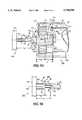
- FIG. 6Ais a partial plan view of a square shaft for engagement with a multi-size photoreceptor flange bearing according to the present invention
- FIG. 6Bis a partial end view of the square shaft of FIG. 6A;
- FIG. 6Cis a partial plan view of a triangular shaft for engagement with a multi-size photoreceptor flange bearing according to the present invention.
- FIG. 6Dis a partial end view of the triangular shaft of FIG. 6C;
- FIG. 6Eis a partial plan view of a pentagon shaft for engagement with a multi-size photoreceptor flange bearing according to the present invention.
- FIG. 6Fis a partial end view of the triangular shaft of FIG. 6E;
- FIG. 6Gis a partial plan view of a hexagonal shaft for engagement with a multi-size photoreceptor flange bearing according to the present invention.
- FIG. 6His a partial end view of the hexagonal shaft of FIG. 6G.
- FIG. 6schematically depicts the various components of an electrophotographic printing machine incorporating the corona discharge device of the present invention therein.
- the corona discharge device of the present inventionis particularly well adapted for use in the illustrative printing machine, it will become evident that these corona discharge devices are equally well suited for use in a wide variety of uses and are not necessarily limited in their application to the particular embodiments shown herein.
- the electrophotographic printing machine shownemploys a photoconductive drum 16, although photoreceptors in the form of a belt are also known, and may be substituted therefor.
- the drum 16has a photoconductive surface deposited on a conductive substrate.
- Drum 16moves in the direction of arrow 18 to advance successive portions thereof sequentially through the various processing stations disposed about the path of movement thereof.
- Motor 26rotates drum 16 to advance drum 16 in the direction of arrow 18.
- Drum 16is coupled to motor 26, by suitable means such as a drive.
- a corona generating deviceindicated generally by the reference numeral 30, charges the drum 16 to a selectively high uniform electrical potential.
- the electrical potentialis normally opposite in sign to the charge of the toner. Depending on the toner chemical composition, the potential may be positive or negative. Any suitable control, well known in the art, may be employed for controlling the corona generating device 30.
- a document 34 to be reproducedis placed on a platen 22, located at imaging station B, where it is illuminated in a known manner by a light source such as a lamp 24 with a photo spectral output matching the photo spectral sensitivity of the photoconductor.
- the document thus exposedis imaged onto the drum 16 by a system of mirrors 26 and lens 27, as shown.
- the optical imageselectively discharges surface 28 of the drum 16 in an image configuration whereby an electrostatic latent image 32 of the original document is recorded on the drum 16 at the imaging station B.
- a development system or unitindicated generally by the reference numeral 36 advances developer materials into contact with the electrostatic latent images.
- the developer unit 36includes a device to advance developer material into contact with the latent image.
- the developer unit 36in the direction of movement of drum 16 as indicated by arrow 18, develops the charged image areas of the photoconductive surface 28.
- This developer unitcontains black developer, for example, material 44 having a triboelectric charge such that the black toner is urged towards charged areas of the latent image by the electrostatic field existing between the photoconductive surface and the electrically biased developer rolls in the developer unit which are connected to bias power supply 42.
- a sheet of support material 58is moved into contact with the toner image at transfer station D.
- the sheet of support material 58is advanced to transfer station D by conventional sheet feeding apparatus, not shown.
- the sheet feeding apparatusincludes a feed roll contacting the uppermost sheet of a stack of copy sheets. Feed rolls rotate so as to advance the uppermost sheet from the stack into a chute which directs the advancing sheet of support material into contact with the photoconductive surface of drum 16 in a timed sequence so that the toner powder image developed thereon contacts the advancing sheet of support material at transfer station D.
- Transfer station Dincludes a corona generating device 60 which sprays ions of a suitable polarity onto the backside of sheet 58. This attracts the toner powder image from the drum 16 to sheet 58. After transfer, the sheet continues to move, in the direction of arrow 62, onto a conveyor (not shown) which advances the sheet to fusing station E.
- Fusing station Eincludes a fuser assembly, indicated generally by the reference numeral 64, which permanently affixes the transferred powder image to sheet 58.
- fuser assembly 64comprises a heated fuser roller 66 and a pressure roller 68.
- Sheet 58passes between fuser roller 66 and pressure roller 68 with the toner powder image contacting fuser roller 66. In this manner, the toner powder image is permanently affixed to sheet 58.
- a chuteguides the advancing sheet 58 to a catch tray, also not shown, for subsequent removal from the printing machine by the operator. It will also be understood that other post-fusing operations can be included, for example, binding, inverting and returning the sheet for duplexing and the like.
- the cleaning station Fincludes a blade 74.
- bearing 100is made of any suitable, durable material such as a metal or a durable synthetic material, for example a plastic.
- the bearingis electrically conductive.
- the bearingalso has inherent lubricating qualities to permit low friction and low wear operation.
- the bearing 100may be made of a bronze, for example, a powder metal sintered material, i.e. bronze.
- the bronze bearing 100is impregnated with a lubricating material, i.e. carbon.
- the bearing 100may be made of an alternate material, i.e. a plastic impregnated with carbon to provide the lubricating and electrically conductive properties.
- the bearing 100may have any suitable shape which permits the rotational motion of the member 16 in the form of for example photoreceptor drum 16 about axis 102.
- the bearing 100has a body 104 which defines a cylindrical periphery 106 thereof.
- the bearing body 104defines a first feature 1 10 as well as a second feature 112.
- the bearing 100supports the member 16 which is typically in the form of a photoconductive drum.
- the bearing 100is connected to the drum 16 in any suitable fashion.
- the drum 16may include a substrate 114 having a general tubular shape.
- the substrateis made of any suitable material and preferably is electrically conductive, for example, aluminum.
- the periphery 28 of the substrate 114is preferably coated with a photoconductive material, i.e. selenium or a organic material.
- the bearing 100is connected to the drum 16 in any suitable fashion.
- hub 116may be used to connect the drum 16 to the bearing 100.
- the hub 116is secured to the photoreceptor drum 16 in any suitable fashion. For example, as shown in FIG.
- the hub 116includes a hub large bore 120 to which periphery 28 of the drum 16 is matingly fitted. It should be appreciated, however, that the hub 116 may include a stem (not shown) which would matingly fit to drum bore 122 of the substrate 14.
- the hub 116is secured to the bearing 100 in any suitable fashion.
- the hub 116may include a small bore 124 which is matingly fitted to periphery 106 of the bearing 100.
- the hub 116may include a gear 130 located on the hub 116.
- the gear 130may include a plurality of teeth 132.
- the teeth 132may have any suitable shape and may, for example, be as shown in FIG. 1A, spur or helical teeth.
- the gear 130mates with a driving gear (not shown) which drives the photoconductive drum 16.
- the hub 116is made of any suitable, durable material, for example, aluminum. It should be appreciated that hub 116 may also be made of a organic material, i.e. a plastic.
- the bearing 100is operably connected to housing 134.
- the housing 134may have any suitable shape for containing the photoconductive drum 16. As stated earlier the photoconductive drum 16 is a consumable item and will eventually require replacement. In order to assist in the placement of the photoconductive drum recently the photoconductive drum is contained within a module or unit in the form of a CRU (customer replaceable unit) generally referred to in FIG. 1A as numeral 136.
- the housing 134thus forms part of the CRU 136.
- the housinghas a generally cylindrical shape slightly larger than the drum 16.
- the housing 134may be made of any suitable durable material for example a plastic in particular a strong plastic perhaps reinforced with fibers for example nylon or carbon graphite material.
- the CRU 136is removable mounted to a first copy machine 140.
- the CRU 136may be mounted to the machine 140 in any suitable fashion, for example as shown in FIG. 1A, the machine 140 includes frame 142 from which first support 144 extends. The CRU 136 is thus removably mounted on support 144.
- the bearing 100serves to permit the mounting of CRU 136 into the first machine 140 which has the first support 144 extending from the frame member 142 (see FIG. 1A) as well as to mount the CRU 136 into machine 240 which machine 240 includes a second support 244 extending from a second frame member 242. More simply stated, the bearing 100 accepts both the first support 144 and the second support 244 permitting the CRU 136 to fit into both machines 140 and 240.
- the bearing 100includes the first feature 1 10 which cooperates with the first support 144 to permit the mounting of the CRU 136 into machine 140.
- the support 144 and the first feature 110may have any suitable shape to permit cooperation with each other.
- the first feature 110may be in the form of a small bore.
- the bore 110may be cylindrical and be defined by diameter D FF .
- the first support 144may be in the form of a first stem or first shaft and be cylindrical with a diameter D FS .
- the diameter D FS of the first shaft 144is slightly smaller than the diameter D FF of the small bore 110 of the bearing 100 to permit insertion therewith.
- the first shaft 144has a length L FS which is similar in length to length L B of the bearing 100.
- the second feature 112 of the bearing 100is in the form of a counterbore having a diameter D SF .
- the small second feature 112 of the bearing 100is matingly fitted to the second support 244.
- the second support 244may have any suitable size and shape to mate with the second feature 112 but preferably, according to FIG. 1B, the second support 244 is in the form of a multi-diameter shaft.
- the multi-diameter shaft 244includes a cylindrical stem 250 which extends from a cylindrical base 252.
- the cylindrical stem 250 and cylindrical base 252are concentric about axis 254.
- the cylindrical base 252has a diameter D B which matingly fits into the second feature 112 of the bearing 100.
- the second feature 112is preferably in the form of a cylindrical counterbore having a diameter D SF .
- Diameter D B of the base 252is slightly smaller than diameter DSF of the second feature 112 of the bearing 100 to permit cooperation therewith.
- the cylindrical stem 250has a diameter D S which is similar to diameter D FS of the first shaft 144.
- the cylindrical base 252has a length L BA which is similar to length L SF of the second feature 112 of the bearing 100.
- the cylindrical stem 250extends length LSTfrom the cylindrical base 252 and extends length Lss from frame member 242.
- the length L ST of the cylindrical stem 250is roughly equivalent to the length L FF of the first feature 110.
- the cylindrical stem 250 and the cylindrical base 252are concentric with each other to an accurate tolerance of say, for example, 0.03 mm.
- the counterbore 1 12 and the small bore 110 of the bearing 100are concentric to each other to a small tolerance of for example 0.03 mm.
- the use of a cast sintered metal bearing 100inherently provides for the accurate concentricity of the counterbore 112 to the small bore 110.
- grinding or other manufacturing techniquescan provide for the accurate concentricity of the cylindrical base 252 to the cylindrical stem 250.
- the shaft 144may include a tapered point 160 which is defined by an included angle of approximately 30 to 150 degrees with 90 degrees being preferable.
- the bearing 100likewise includes a lead-in chamfer 162 which defines a chamfer diameter D SC slightly larger than D SF of the bore.
- the chamfer 162is defined further by an included angle II of for example, 150 to 30 degrees with 90 degrees being preferred.
- the transition between the second feature 112 and the first feature 110preferably includes a lead-in chamfer 164 which assists in the insertion of the first shaft 144 and the second shaft 244.
- the cylindrical base 252includes a lead-in chamfer 260 which is defined by angle Angle has an included angle of for example 150 to 30 degrees with 90 degrees being preferred.
- Cylindrical stem 250includes tapered point 262 which is defined by included angle ⁇ . Included angle ⁇ may have any suitable angle of for example 30 to 150 degrees with 90 degrees being preferred.
- the CRU 136is shown installed into machine 240.
- the photoreceptive drum 16includes the first hub 116 extending from first end 170 of the drum 16 as well as second hub 174 extending from second end 172 of the drum 16.
- the photoreceptive drum 16 25is supported at second end 172 in any suitable fashion, for example, as shown in FIG. 3, the second hub 174 is fitted into pot 176.
- a bearing sleeve fitted into a shaftas similar to bearing 100 and shaft 244 may be utilized to support second hub 174.
- cartridge replaceable unit 136is shown trying to be installed into machine 340.
- Machine 340includes shaft 344 which has a diameter DVL which is significantly larger than diameter DSF Of the bearing 100. It is thus obvious that CRU 136 may not be installed into machine 340. Therefore, the bearing 100 serves to foolproof or prevent the installation of CRU 136 into machine 340.
- CRU 436is shown installed into machine 440.
- CRU 436is very similar to CRU 136 of FIGS. 1 and 4 except that second hub 474 is different than second hub 174 of FIG. 3 in that second hub 474 includes bearing 480 which matingly fits with second end shaft 482. Further, CRU 436 includes shaft 444 which matingly fits with first feature 410 of bearing 400.
- CRU 136 as shown in FIGS. 3 and 4 as well as CRU 436 as shown in FIG. 5may operate by having the hub rotate around the bearing or by having the shaft rotate about the bearing.
- the bearing 100rotates about shaft 144 for the CRU 136, while the bearing 400 rotates about shaft 444 in CRU 436.
- the shaft and bearing configurations as shown in FIGS. 6A-6Hare permissible.
- the shaftmay include a portion in the form of a polygon while the bearing may include a bore which mates with the polygon feature of the shaft.
- shaft 544is shown installed in bearing 500.
- Shaft 544includes rectangular base 552 with a cylindrical stem 550 extending therefrom.
- the bearing 500includes a cylindrical first feature 510 as well as a rectangular counterbore 512.
- shaft 644is shown installed in bearing 600 on machine 640.
- the shaft 644includes a cylindrical stem 650 extending from triangular base 652.
- the bearing 600includes a cylindrical bore 610 as well as a triangularly shaped counterbore 612.
- shaft 744is shown installed in bearing 700 on machine 740.
- the shaft 744includes a cylindrical stem 750 extending from pentagon shaped base 752.
- the bearing 700includes a cylindrical bore 710 as well as a pentagon shaped counterbore 712.
- shaft 844is shown installed in bearing 800 on machine 840.
- the shaft 840includes a cylindrical stem 850 extending from hexagonal base 852.
- the bearing 800includes a cylindrical bore 810 as well as a hexagon shaped counterbore 812.
- FIGS. 6A-6Hrequire a correspondingly matingly shaped bore to permit the assembly of the shaft into the bearing. This configuration is very helpful for foolproofing of the proper CRU into a copy machine. While the configuration shown in FIGS. 6A-6H require the rotation of the hub about the bearing, it should be appreciated that by replacing the polygon counterbore within the bearing with a counterbore within the housing the bearing 100 could rotate about the cylindrical stem obviating the need for a rotation between the bearing and the hub.
- common photoreceptorsmay be used reducing the number of different photoreceptors resulting in lower inventory, larger lot sizes, fewer changeovers, and thereby lower costs for the photoreceptors and cartridge replaceable units.
- a CRUmay be provided with improved life.
- charge transfercan occur through the bearing of the CRU.
Landscapes
- Engineering & Computer Science (AREA)
- General Engineering & Computer Science (AREA)
- Physics & Mathematics (AREA)
- General Physics & Mathematics (AREA)
- Mechanical Engineering (AREA)
- Discharging, Photosensitive Material Shape In Electrophotography (AREA)
- Rolls And Other Rotary Bodies (AREA)
Abstract
Description
______________________________________ U.S. Pat. No. A-5,465,136 Patentee: Watanabe Issue Date: November 7, 1994 U.S. Pat. No. A-5,357,321 Patentee: Stenzel et al. Issue Date: October 18, 1994 U.S. Pat. No. A-5,151,737 Patentee; Johnson et al Issue Date: September 29, 1992 U.S. Pat. No. A-5,107,304 Patentee: Haneda et al. Issue Date: April 21, 1992 U.S. Pat. No. A-4,996,566 Patentee: Morita et al. Issue Date: February 26, 1991 U.S. Pat. No. A-4,954,844 Patentee: Morita et al. Issue Date: September 4, 1990 U.S. Pat. No. A-4,941,018 Patentee: Kasamura et al. Issue Date: July 10, 1990 U.S. Pat. No. A-4,878,091 Patentee: Morita et al. Issue Date: October 31, 1989 U.S. Pat. No. A-4,621,919 Patentee: Nitanda et al. Issue Date: November 11, 1986 U.S. Pat. No. A-4,561,763 Patentee: Basch Issue Date: December 31, 1985 U.S. Pat. No. A-4,400,077 Patentee: Kozuka et al. Issue Date: August 23, 1983 U.S. Pat. No. A-4,120,576 Patentee: Babish Issue Date: October 17, 1978 U.S. Pat. No. A-4,105,345 Patentee: Van Wagner Issue Date: August 8, 1978 U.S. Pat. No. A-4,040,157 Patentee: Shanly Issue Date: August 9, 1977 U.S. Pat. No. A-3,994,053 Patentee: Hunt Issue Date: November 30, 1976 ______________________________________
Claims (27)
Priority Applications (3)
| Application Number | Priority Date | Filing Date | Title |
|---|---|---|---|
| US08/672,344US5749028A (en) | 1996-06-26 | 1996-06-26 | Multi-size photoreceptor flange bearing |
| MX9703418AMX9703418A (en) | 1996-06-26 | 1997-05-09 | Multi-size photoreceptor flange bearing. |
| BR9703724ABR9703724A (en) | 1996-06-26 | 1997-06-26 | Drum flange bearing of various sizes |
Applications Claiming Priority (1)
| Application Number | Priority Date | Filing Date | Title |
|---|---|---|---|
| US08/672,344US5749028A (en) | 1996-06-26 | 1996-06-26 | Multi-size photoreceptor flange bearing |
Publications (1)
| Publication Number | Publication Date |
|---|---|
| US5749028Atrue US5749028A (en) | 1998-05-05 |
Family
ID=24698150
Family Applications (1)
| Application Number | Title | Priority Date | Filing Date |
|---|---|---|---|
| US08/672,344Expired - Fee RelatedUS5749028A (en) | 1996-06-26 | 1996-06-26 | Multi-size photoreceptor flange bearing |
Country Status (3)
| Country | Link |
|---|---|
| US (1) | US5749028A (en) |
| BR (1) | BR9703724A (en) |
| MX (1) | MX9703418A (en) |
Cited By (18)
| Publication number | Priority date | Publication date | Assignee | Title |
|---|---|---|---|---|
| US6006058A (en)* | 1996-09-26 | 1999-12-21 | Canon Kabushiki Kaisha | Process cartridge and electrophotographic image forming apparatus having an improved driving system |
| US6011942A (en)* | 1997-05-29 | 2000-01-04 | Minolta Co., Ltd. | Cylindrical rotating member having a support mechanism exhibiting little unevenness in rotation, and image forming apparatus |
| US6226478B1 (en)* | 1996-03-21 | 2001-05-01 | Canon Kabushiki Kaisha | Process cartridge having drive mount for photosensitive drum |
| US6240266B1 (en)* | 1996-03-21 | 2001-05-29 | Canon Kabushiki Kaisha | Process cartridge and drum mount for photosensitive drum |
| US6266503B1 (en)* | 1998-08-31 | 2001-07-24 | Canon Kabushiki Kaisha | Method for attaching electrostatic photosensitive drum method for replacing electrophotographic photosensitive drum and process cartridge |
| US6336018B1 (en)* | 1996-09-26 | 2002-01-01 | Canon Kabushiki Kaisha | Electrophotographic image forming apparatus, process cartridge, and drive mount for photosensitive drum |
| EP1199610A3 (en)* | 2000-10-20 | 2005-02-16 | Canon Kabushiki Kaisha | Driving force transmission mechanism, image forming apparatus equipped with such a mechanism, and process unit of such an apparatus |
| US20050163535A1 (en)* | 2004-01-27 | 2005-07-28 | Sharp Kabushiki Kaisha | Gear mechanism and image forming apparatus using same |
| US20060151652A1 (en)* | 2004-12-21 | 2006-07-13 | Imation Corp. | Tape reel assembly having an end plate defining a polygonal drive bore |
| US20060239714A1 (en)* | 2005-04-22 | 2006-10-26 | Dae-Seob Kweon | Photoreceptors,developing cartridge using the same, and image forming apparatus using the same |
| US20070009286A1 (en)* | 2005-07-08 | 2007-01-11 | Lexmark International, Inc. | Drum support bushing with orienting features |
| US20090154953A1 (en)* | 2005-07-28 | 2009-06-18 | Static Control Components, Inc. | Systems and methods for remanufacturing imaging components |
| CN1763638B (en)* | 2000-10-20 | 2010-06-09 | 佳能株式会社 | Image forming apparatus |
| US9176468B2 (en) | 2006-12-22 | 2015-11-03 | Canon Kabushiki Kaisha | Rotational force transmitting part |
| US9477201B2 (en) | 2008-06-20 | 2016-10-25 | Canon Kabushiki Kaisha | Cartridge, mounting method for coupling member, and disassembling method for coupling member |
| US9678471B2 (en) | 2006-12-22 | 2017-06-13 | Canon Kabushiki Kaisha | Process cartridge, electrophotographic image forming apparatus, and electrophotographic photosensitive drum unit |
| US9703257B2 (en) | 2007-03-23 | 2017-07-11 | Canon Kabushiki Kaisha | Electrophotographic image forming apparatus, developing apparatus, and coupling member |
| KR20210008572A (en)* | 2018-06-19 | 2021-01-22 | 어플라이드 머티어리얼스, 인코포레이티드 | Deposition system with shield mount |
Citations (21)
| Publication number | Priority date | Publication date | Assignee | Title |
|---|---|---|---|---|
| US3994053A (en)* | 1976-01-08 | 1976-11-30 | Xerox Corporation | Drum support apparatus |
| US4040157A (en)* | 1976-01-08 | 1977-08-09 | Xerox Corporation | Drum support apparatus |
| US4105345A (en)* | 1976-02-27 | 1978-08-08 | Xerox Corporation | Expandable photoreceptor endbells |
| US4120576A (en)* | 1977-04-04 | 1978-10-17 | Xerox Corporation | Drum support apparatus |
| US4400077A (en)* | 1980-11-12 | 1983-08-23 | Mita Industrial Company Limited | Photosensitive drum for electrostatic copying apparatus |
| US4449809A (en)* | 1981-12-28 | 1984-05-22 | Konishiroku Photo Industry Co., Ltd. | Drive unit mounting mechanism for reproducing apparatus |
| US4561763A (en)* | 1984-08-03 | 1985-12-31 | Xerox Corporation | Drum support apparatus |
| US4621919A (en)* | 1983-07-13 | 1986-11-11 | Canon Kabushiki Kaisha | Metal drum and image holding member using the same |
| US4839690A (en)* | 1985-09-17 | 1989-06-13 | Canon Kabushiki Kaisha | Image bearing member usable with image forming apparatus |
| US4878091A (en)* | 1987-09-17 | 1989-10-31 | Konica Corporation | Multicolor image forming apparatus |
| US4941018A (en)* | 1986-10-28 | 1990-07-10 | Canon Kabushiki Kaisha | Developing device accommodating apparatus and image forming apparatus and developing device |
| US4954844A (en)* | 1987-12-17 | 1990-09-04 | Konica Corporation | Multicolor image developing device |
| US4996566A (en)* | 1988-11-01 | 1991-02-26 | Konica Corporation | Multicolor image forming apparatus with separately removable and insertable assembly units |
| US5107304A (en)* | 1989-02-21 | 1992-04-21 | Konica Corporation | Removable cartridge for a color image forming apparatus |
| US5128715A (en)* | 1990-03-19 | 1992-07-07 | Fuji Xerox Co., Ltd. | Print cartidge and image forming apparatus employing the same |
| US5151737A (en)* | 1990-06-04 | 1992-09-29 | Eastman Kodak Company | Photoconductive drum having expandable mount |
| US5347343A (en)* | 1992-07-16 | 1994-09-13 | Sharp Kabushiki Kaisha | Photosensitive drum cartridge and an image forming apparatus using the same |
| US5357321A (en)* | 1994-01-04 | 1994-10-18 | Xerox Corporation | Drum supporting hub and drum assembly |
| US5402207A (en)* | 1993-12-30 | 1995-03-28 | Michlin; Steven B. | Long-life and improved photoreceptor drum gear |
| US5444516A (en)* | 1994-04-28 | 1995-08-22 | Steven Bruce Michlin | Photoreceptor drum axle improvement |
| US5465136A (en)* | 1993-03-23 | 1995-11-07 | Canon Kabushiki Kaisha | Image forming apparatus and process cartridge detachable thereto with charging member pressure contact release feature |
- 1996
- 1996-06-26USUS08/672,344patent/US5749028A/ennot_activeExpired - Fee Related
- 1997
- 1997-05-09MXMX9703418Apatent/MX9703418A/ennot_activeIP Right Cessation
- 1997-06-26BRBR9703724Apatent/BR9703724A/ennot_activeIP Right Cessation
Patent Citations (21)
| Publication number | Priority date | Publication date | Assignee | Title |
|---|---|---|---|---|
| US3994053A (en)* | 1976-01-08 | 1976-11-30 | Xerox Corporation | Drum support apparatus |
| US4040157A (en)* | 1976-01-08 | 1977-08-09 | Xerox Corporation | Drum support apparatus |
| US4105345A (en)* | 1976-02-27 | 1978-08-08 | Xerox Corporation | Expandable photoreceptor endbells |
| US4120576A (en)* | 1977-04-04 | 1978-10-17 | Xerox Corporation | Drum support apparatus |
| US4400077A (en)* | 1980-11-12 | 1983-08-23 | Mita Industrial Company Limited | Photosensitive drum for electrostatic copying apparatus |
| US4449809A (en)* | 1981-12-28 | 1984-05-22 | Konishiroku Photo Industry Co., Ltd. | Drive unit mounting mechanism for reproducing apparatus |
| US4621919A (en)* | 1983-07-13 | 1986-11-11 | Canon Kabushiki Kaisha | Metal drum and image holding member using the same |
| US4561763A (en)* | 1984-08-03 | 1985-12-31 | Xerox Corporation | Drum support apparatus |
| US4839690A (en)* | 1985-09-17 | 1989-06-13 | Canon Kabushiki Kaisha | Image bearing member usable with image forming apparatus |
| US4941018A (en)* | 1986-10-28 | 1990-07-10 | Canon Kabushiki Kaisha | Developing device accommodating apparatus and image forming apparatus and developing device |
| US4878091A (en)* | 1987-09-17 | 1989-10-31 | Konica Corporation | Multicolor image forming apparatus |
| US4954844A (en)* | 1987-12-17 | 1990-09-04 | Konica Corporation | Multicolor image developing device |
| US4996566A (en)* | 1988-11-01 | 1991-02-26 | Konica Corporation | Multicolor image forming apparatus with separately removable and insertable assembly units |
| US5107304A (en)* | 1989-02-21 | 1992-04-21 | Konica Corporation | Removable cartridge for a color image forming apparatus |
| US5128715A (en)* | 1990-03-19 | 1992-07-07 | Fuji Xerox Co., Ltd. | Print cartidge and image forming apparatus employing the same |
| US5151737A (en)* | 1990-06-04 | 1992-09-29 | Eastman Kodak Company | Photoconductive drum having expandable mount |
| US5347343A (en)* | 1992-07-16 | 1994-09-13 | Sharp Kabushiki Kaisha | Photosensitive drum cartridge and an image forming apparatus using the same |
| US5465136A (en)* | 1993-03-23 | 1995-11-07 | Canon Kabushiki Kaisha | Image forming apparatus and process cartridge detachable thereto with charging member pressure contact release feature |
| US5402207A (en)* | 1993-12-30 | 1995-03-28 | Michlin; Steven B. | Long-life and improved photoreceptor drum gear |
| US5357321A (en)* | 1994-01-04 | 1994-10-18 | Xerox Corporation | Drum supporting hub and drum assembly |
| US5444516A (en)* | 1994-04-28 | 1995-08-22 | Steven Bruce Michlin | Photoreceptor drum axle improvement |
Cited By (80)
| Publication number | Priority date | Publication date | Assignee | Title |
|---|---|---|---|---|
| US6226478B1 (en)* | 1996-03-21 | 2001-05-01 | Canon Kabushiki Kaisha | Process cartridge having drive mount for photosensitive drum |
| US6240266B1 (en)* | 1996-03-21 | 2001-05-29 | Canon Kabushiki Kaisha | Process cartridge and drum mount for photosensitive drum |
| US6501926B1 (en) | 1996-03-21 | 2002-12-31 | Canon Kabushiki Kaisha | Process cartridge and electrophotographic image forming apparatus |
| US6501927B1 (en) | 1996-03-21 | 2002-12-31 | Canon Kabushiki Kaisha | Process cartridge and photosensitive drum driving mount |
| US6336018B1 (en)* | 1996-09-26 | 2002-01-01 | Canon Kabushiki Kaisha | Electrophotographic image forming apparatus, process cartridge, and drive mount for photosensitive drum |
| US6006058A (en)* | 1996-09-26 | 1999-12-21 | Canon Kabushiki Kaisha | Process cartridge and electrophotographic image forming apparatus having an improved driving system |
| US6011942A (en)* | 1997-05-29 | 2000-01-04 | Minolta Co., Ltd. | Cylindrical rotating member having a support mechanism exhibiting little unevenness in rotation, and image forming apparatus |
| US6266503B1 (en)* | 1998-08-31 | 2001-07-24 | Canon Kabushiki Kaisha | Method for attaching electrostatic photosensitive drum method for replacing electrophotographic photosensitive drum and process cartridge |
| US7092658B2 (en) | 2000-10-20 | 2006-08-15 | Canon Kabushiki Kaisha | Driving force transmission mechanism, image forming apparatus equipped with such a mechanism, and process unit of such an apparatus |
| EP1199610A3 (en)* | 2000-10-20 | 2005-02-16 | Canon Kabushiki Kaisha | Driving force transmission mechanism, image forming apparatus equipped with such a mechanism, and process unit of such an apparatus |
| US20050089345A1 (en)* | 2000-10-20 | 2005-04-28 | Canon Kabushiki Kaisha | Driving force transmission mechanism, image forming apparatus equipped with such a mechanism, and process unit of such an apparatus |
| CN1763638B (en)* | 2000-10-20 | 2010-06-09 | 佳能株式会社 | Image forming apparatus |
| US20050163535A1 (en)* | 2004-01-27 | 2005-07-28 | Sharp Kabushiki Kaisha | Gear mechanism and image forming apparatus using same |
| US7245858B2 (en)* | 2004-01-27 | 2007-07-17 | Sharp Kabushiki Kaisha | Gear mechanism and image forming apparatus using same |
| US20060151652A1 (en)* | 2004-12-21 | 2006-07-13 | Imation Corp. | Tape reel assembly having an end plate defining a polygonal drive bore |
| US20060239714A1 (en)* | 2005-04-22 | 2006-10-26 | Dae-Seob Kweon | Photoreceptors,developing cartridge using the same, and image forming apparatus using the same |
| US7433628B2 (en) | 2005-04-22 | 2008-10-07 | Samsung Electronics Co., Ltd. | Photoreceptors, developing cartridge using the same, and image forming apparatus using the same |
| US20070009286A1 (en)* | 2005-07-08 | 2007-01-11 | Lexmark International, Inc. | Drum support bushing with orienting features |
| US7330680B2 (en) | 2005-07-08 | 2008-02-12 | Lexmark International, Inc. | Drum support bushing with orienting features |
| US20090154953A1 (en)* | 2005-07-28 | 2009-06-18 | Static Control Components, Inc. | Systems and methods for remanufacturing imaging components |
| US7742719B2 (en)* | 2005-07-28 | 2010-06-22 | Static Control Components, Inc. | Systems and methods for remanufacturing imaging components |
| US9857765B2 (en) | 2006-12-22 | 2018-01-02 | Canon Kabushiki Kaisha | Process cartridge, electrophotographic image forming apparatus, and electrophotographic photosensitive drum unit |
| US10429794B2 (en) | 2006-12-22 | 2019-10-01 | Canon Kabushiki Kaisha | Rotational force transmitting part |
| US12405567B2 (en) | 2006-12-22 | 2025-09-02 | Canon Kabushiki Kaisha | Process cartridge, electrophotographic image forming apparatus, and electrophotographic photosensitive drum unit |
| US9678471B2 (en) | 2006-12-22 | 2017-06-13 | Canon Kabushiki Kaisha | Process cartridge, electrophotographic image forming apparatus, and electrophotographic photosensitive drum unit |
| US11720054B2 (en) | 2006-12-22 | 2023-08-08 | Canon Kabushiki Kaisha | Process cartridge, electrophotographic image forming apparatus, and electrophotographic photosensitive drum unit |
| US9733614B2 (en) | 2006-12-22 | 2017-08-15 | Canon Kabushiki Kaisha | Process cartridge, electrophotographic image forming apparatus, and electrophotographic photosensitive drum unit |
| US9746826B2 (en) | 2006-12-22 | 2017-08-29 | Canon Kabushiki Kaisha | Process cartridge, electrophotographic image forming apparatus, and electrophotographic photosensitive drum unit |
| US9772602B2 (en) | 2006-12-22 | 2017-09-26 | Canon Kabushiki Kaisha | Rotational force transmitting part |
| US11237517B2 (en) | 2006-12-22 | 2022-02-01 | Canon Kabushiki Kaisha | Process cartridge, electrophotographic image forming apparatus, and electrophotographic photosensitive drum unit |
| US11156956B2 (en) | 2006-12-22 | 2021-10-26 | Canon Kabushiki Kaisha | Rotational force transmitting part |
| US9836021B2 (en) | 2006-12-22 | 2017-12-05 | Canon Kabushiki Kaisha | Process cartridge, electrophotographic image forming apparatus, and electrophotographic photosensitive drum unit |
| US10877433B2 (en) | 2006-12-22 | 2020-12-29 | Canon Kabushiki Kaisha | Process cartridge, electrophotographic image forming apparatus, and electrophotographic photosensitive drum unit |
| US9841727B2 (en) | 2006-12-22 | 2017-12-12 | Canon Kabushiki Kaisha | Process cartridge, electrophotographic image forming apparatus, and electrophotographic photosensitive drum unit |
| US9841729B2 (en) | 2006-12-22 | 2017-12-12 | Canon Kabushiki Kaisha | Process cartridge, electrophotographic image forming apparatus, and electrophotographic photosensitive drum unit |
| US9841728B2 (en) | 2006-12-22 | 2017-12-12 | Canon Kabushiki Kaisha | Process cartridge having changeable relative positioning of a coupling member and another part of the process cartridge |
| US9846408B2 (en) | 2006-12-22 | 2017-12-19 | Canon Kabushiki Kaisha | Process cartridge, electrophotographic image forming apparatus, and electrophotographic photosensitive drum unit |
| US10845756B2 (en) | 2006-12-22 | 2020-11-24 | Canon Kabushiki Kaisha | Rotational force transmitting part |
| US10671018B2 (en) | 2006-12-22 | 2020-06-02 | Canon Kabushiki Kaisha | Process cartridge, electrophotographic image forming apparatus, and electrophotographic photosensitive drum unit |
| US9857764B2 (en) | 2006-12-22 | 2018-01-02 | Canon Kabushiki Kaisha | Process cartridge, electrophotographic image forming apparatus, and electrophotographic photosensitive drum unit |
| US10585391B2 (en) | 2006-12-22 | 2020-03-10 | Canon Kabushiki Kaisha | Process cartridge, electrophotographic image forming apparatus, and electrophotographic photosensitive drum unit |
| US9176468B2 (en) | 2006-12-22 | 2015-11-03 | Canon Kabushiki Kaisha | Rotational force transmitting part |
| US9864333B2 (en) | 2006-12-22 | 2018-01-09 | Canon Kabushiki Kaisha | Process cartridge, electrophotographic image forming apparatus, and electrophotographic photosensitive drum unit |
| US9864331B2 (en) | 2006-12-22 | 2018-01-09 | Canon Kabushiki Kaisha | Process cartridge, electrophotographic image forming apparatus, and electrophotographic photosensitive drum unit |
| US9869960B2 (en) | 2006-12-22 | 2018-01-16 | Canon Kabushiki Kaisha | Process cartridge, electrophotographic image forming apparatus, and electrophotographic photosensitive drum unit |
| US9874854B2 (en) | 2006-12-22 | 2018-01-23 | Canon Kabushiki Kaisha | Process cartridge, electrophotographic image forming apparatus, and electrophotographic photosensitive drum unit |
| US9874846B2 (en) | 2006-12-22 | 2018-01-23 | Canon Kabushiki Kaisha | Process cartridge, electrophotographic image forming apparatus, and electrophotographic photosensitive drum unit |
| US10551793B2 (en) | 2006-12-22 | 2020-02-04 | Canon Kabushiki Kaisha | Process cartridge, electrophotographic image forming apparatus, and electrophotographic photosensitive drum unit |
| US10539923B2 (en) | 2006-12-22 | 2020-01-21 | Canon Kabushiki Kaisha | Process cartridge, electrophotographic image forming apparatus, and electrophotographic photosensitive drum unit |
| US10539924B2 (en) | 2006-12-22 | 2020-01-21 | Canon Kabushiki Kaisha | Process cartridge, electrophotographic image forming apparatus, and electrophotographic photosensitive drum unit |
| US10209670B2 (en) | 2006-12-22 | 2019-02-19 | Canon Kabushiki Kaisha | Rotational force transmitting part |
| US10816931B2 (en) | 2007-03-23 | 2020-10-27 | Canon Kabushiki Kaisha | Electrophotographic image forming apparatus, developing apparatus, and coupling member |
| US10712710B2 (en) | 2007-03-23 | 2020-07-14 | Canon Kabushiki Kaisha | Electrophotographic image forming apparatus, developing apparatus, and coupling member |
| US12298704B2 (en) | 2007-03-23 | 2025-05-13 | Canon Kabushiki Kaisha | Electrophotographic image forming apparatus, developing apparatus, and coupling member |
| US9939776B2 (en) | 2007-03-23 | 2018-04-10 | Canon Kabushiki Kaisha | Electrophotographic image forming apparatus, developing apparatus, and coupling member |
| US9703257B2 (en) | 2007-03-23 | 2017-07-11 | Canon Kabushiki Kaisha | Electrophotographic image forming apparatus, developing apparatus, and coupling member |
| US9886002B2 (en) | 2007-03-23 | 2018-02-06 | Canon Kabushiki Kaisha | Electrophotographic image forming apparatus, developing apparatus, and coupling member |
| US9857766B2 (en) | 2007-03-23 | 2018-01-02 | Canon Kabushiki Kaisha | Electrophotographic image forming apparatus, developing apparatus, and coupling member |
| US10620582B2 (en) | 2007-03-23 | 2020-04-14 | Canon Kabushiki Kaisha | Electrophotographic image forming apparatus, developing apparatus, and coupling member |
| US9851685B2 (en) | 2007-03-23 | 2017-12-26 | Canon Kabushiki Kaisha | Electrophotographic image forming apparatus, developing apparatus, and coupling member |
| US9836015B2 (en) | 2007-03-23 | 2017-12-05 | Canon Kabushiki Kaisha | Electrophotographic image forming apparatus, developing apparatus, and coupling member |
| US10712709B2 (en) | 2007-03-23 | 2020-07-14 | Canon Kabushiki Kaisha | Electrophotographic image forming apparatus, developing apparatus, and coupling member |
| US10788790B2 (en) | 2007-03-23 | 2020-09-29 | Canon Kabushiki Kaisha | Electrophotographic image forming apparatus, developing apparatus, and coupling member |
| US10788789B2 (en) | 2007-03-23 | 2020-09-29 | Canon Kabushiki Kaisha | Electrophotographic image forming apparatus, developing apparatus, and coupling member |
| US10795312B2 (en) | 2007-03-23 | 2020-10-06 | Canon Kabushiki Kaisha | Electrophotographic image forming apparatus, developing apparatus, and coupling member |
| US10520887B2 (en) | 2007-03-23 | 2019-12-31 | Canon Kabushiki Kaisha | Electrophotographic image forming apparatus, developing apparatus, and coupling member |
| US11675308B2 (en) | 2007-03-23 | 2023-06-13 | Canon Kabushiki Kaisha | Electrophotographic image forming apparatus, developing apparatus, and coupling member |
| US9817333B2 (en) | 2007-03-23 | 2017-11-14 | Canon Kabushiki Kaisha | Electrophotographic image forming apparatus, developing apparatus, and coupling member |
| US9841724B2 (en) | 2007-03-23 | 2017-12-12 | Canon Kabushiki Kaisha | Image forming apparatus cartridge having changeable relative positioning of a coupling member and another part of the image forming apparatus cartridge |
| US11204584B2 (en) | 2007-03-23 | 2021-12-21 | Canon Kabushiki Kaisha | Electrophotographic image forming apparatus, developing apparatus, and coupling member |
| US9851688B2 (en) | 2007-03-23 | 2017-12-26 | Canon Kabushiki Kaisha | Electrophotographic image forming apparatus, developing apparatus, and coupling member |
| US11209772B2 (en) | 2008-06-20 | 2021-12-28 | Canon Kabushiki Kaisha | Cartridge, mounting method for coupling member, and disassemblying method for coupling member |
| US10901360B2 (en) | 2008-06-20 | 2021-01-26 | Canon Kabushiki Kaisha | Cartridge, mounting method for coupling member, and disassembling method for coupling member |
| US9477201B2 (en) | 2008-06-20 | 2016-10-25 | Canon Kabushiki Kaisha | Cartridge, mounting method for coupling member, and disassembling method for coupling member |
| US10545450B2 (en) | 2008-06-20 | 2020-01-28 | Canon Kabushiki Kaisha | Cartridge, mounting method for coupling member, and disassembling method for coupling member |
| US10095179B2 (en) | 2008-06-20 | 2018-10-09 | Canon Kabushiki Kaisha | Cartridge, mounting method for coupling member, and disassembling method for coupling member |
| US9594343B2 (en) | 2008-06-20 | 2017-03-14 | Canon Kabushiki Kaisha | Cartridge, mounting method for coupling member, and disassembling method for coupling member |
| KR20210008572A (en)* | 2018-06-19 | 2021-01-22 | 어플라이드 머티어리얼스, 인코포레이티드 | Deposition system with shield mount |
| US11236415B2 (en)* | 2018-06-19 | 2022-02-01 | Applied Materials, Inc. | Deposition system with shield mount |
| JP2021528561A (en)* | 2018-06-19 | 2021-10-21 | アプライド マテリアルズ インコーポレイテッドApplied Materials,Incorporated | Sedimentary system with shield mount |
Also Published As
| Publication number | Publication date |
|---|---|
| BR9703724A (en) | 1998-09-22 |
| MX9703418A (en) | 1997-12-31 |
Similar Documents
| Publication | Publication Date | Title |
|---|---|---|
| US5749028A (en) | Multi-size photoreceptor flange bearing | |
| US5457520A (en) | Dual snap fit bearing | |
| US6463237B2 (en) | Image forming apparatus and charge roller therefor | |
| JPS6142676A (en) | Drum support apparatus | |
| US5579093A (en) | Resiliently biased end caps for photoconductive drums | |
| EP0784250B1 (en) | Process cartridge, development apparatus, and electrophoto-graphic image formation apparatus | |
| KR20010020799A (en) | Developing device and electric energy supply part for applying developing bias voltage | |
| US5220386A (en) | Image forming apparatus having cleanable transfer material carrying means | |
| US6298203B1 (en) | Developing apparatus featuring suppressed deviation of a positional relationship between a developer bearing member and a developer regulator member and method for assembling the apparatus | |
| US5497224A (en) | Image forming apparatus | |
| US6445896B1 (en) | Image forming apparatus including a charging device that contacts a portion of an image carrier belt spanning a driving roller and method of use | |
| JP3517475B2 (en) | Image forming device | |
| JP3279780B2 (en) | Roller positioning device for image forming apparatus | |
| JP4361256B2 (en) | Image forming apparatus and process cartridge | |
| EP0620508A1 (en) | Augmented electrostatic brush | |
| JPH07210056A (en) | Cleaning device | |
| US5541709A (en) | Method and apparatus for changing a drum surface in a printing apparatus | |
| JP3720522B2 (en) | Electrophotographic image forming apparatus | |
| JPS62187376A (en) | Recorder | |
| JPH0728377A (en) | Image forming device | |
| JPS61118769A (en) | Image forming device | |
| JP2008275893A (en) | Image forming apparatus | |
| KR100389850B1 (en) | Printing method of electrophotographic printing machine | |
| JPH11288188A (en) | Image forming device | |
| KR100262512B1 (en) | Blade of electronograph developing device |
Legal Events
| Date | Code | Title | Description |
|---|---|---|---|
| AS | Assignment | Owner name:XEROX CORPORATION, CONNECTICUT Free format text:ASSIGNMENT OF ASSIGNORS INTEREST;ASSIGNORS:DAMJI, DHIRENDRA C.;HERZOG, RICHARD W.;REEL/FRAME:008092/0244 Effective date:19960626 | |
| FPAY | Fee payment | Year of fee payment:4 | |
| AS | Assignment | Owner name:BANK ONE, NA, AS ADMINISTRATIVE AGENT, ILLINOIS Free format text:SECURITY INTEREST;ASSIGNOR:XEROX CORPORATION;REEL/FRAME:013153/0001 Effective date:20020621 | |
| AS | Assignment | Owner name:JPMORGAN CHASE BANK, AS COLLATERAL AGENT, TEXAS Free format text:SECURITY AGREEMENT;ASSIGNOR:XEROX CORPORATION;REEL/FRAME:015134/0476 Effective date:20030625 Owner name:JPMORGAN CHASE BANK, AS COLLATERAL AGENT,TEXAS Free format text:SECURITY AGREEMENT;ASSIGNOR:XEROX CORPORATION;REEL/FRAME:015134/0476 Effective date:20030625 | |
| REMI | Maintenance fee reminder mailed | ||
| LAPS | Lapse for failure to pay maintenance fees | ||
| STCH | Information on status: patent discontinuation | Free format text:PATENT EXPIRED DUE TO NONPAYMENT OF MAINTENANCE FEES UNDER 37 CFR 1.362 | |
| FP | Lapsed due to failure to pay maintenance fee | Effective date:20060505 | |
| AS | Assignment | Owner name:XEROX CORPORATION, CONNECTICUT Free format text:RELEASE BY SECURED PARTY;ASSIGNOR:JPMORGAN CHASE BANK, N.A. AS SUCCESSOR-IN-INTEREST ADMINISTRATIVE AGENT AND COLLATERAL AGENT TO JPMORGAN CHASE BANK;REEL/FRAME:066728/0193 Effective date:20220822 |