US5748655A - Intracavity modulated pulsed laser and methods of using the same - Google Patents
Intracavity modulated pulsed laser and methods of using the sameDownload PDFInfo
- Publication number
- US5748655A US5748655AUS08/597,998US59799896AUS5748655AUS 5748655 AUS5748655 AUS 5748655AUS 59799896 AUS59799896 AUS 59799896AUS 5748655 AUS5748655 AUS 5748655A
- Authority
- US
- United States
- Prior art keywords
- laser
- flashlamp
- pulsed
- pulse
- output
- Prior art date
- Legal status (The legal status is an assumption and is not a legal conclusion. Google has not performed a legal analysis and makes no representation as to the accuracy of the status listed.)
- Expired - Lifetime
Links
- 238000000034methodMethods0.000titleclaimsabstractdescription14
- 230000003321amplificationEffects0.000claimsabstractdescription33
- 238000003199nucleic acid amplification methodMethods0.000claimsabstractdescription33
- 239000013078crystalSubstances0.000claimsabstractdescription14
- 230000003287optical effectEffects0.000claimsdescription14
- 230000010355oscillationEffects0.000claimsdescription14
- 230000004044responseEffects0.000claimsdescription6
- 238000005086pumpingMethods0.000abstractdescription12
- 229910019655synthetic inorganic crystalline materialInorganic materials0.000description41
- 239000000835fiberSubstances0.000description18
- 210000001519tissueAnatomy0.000description15
- 238000000576coating methodMethods0.000description12
- 239000011248coating agentSubstances0.000description9
- 238000002679ablationMethods0.000description7
- 230000006378damageEffects0.000description7
- 238000010586diagramMethods0.000description7
- 230000003466anti-cipated effectEffects0.000description6
- 230000003667anti-reflective effectEffects0.000description6
- 230000006870functionEffects0.000description6
- JNDMLEXHDPKVFC-UHFFFAOYSA-Naluminum;oxygen(2-);yttrium(3+)Chemical compound[O-2].[O-2].[O-2].[Al+3].[Y+3]JNDMLEXHDPKVFC-UHFFFAOYSA-N0.000description4
- 238000010304firingMethods0.000description4
- 229910052732germaniumInorganic materials0.000description4
- GNPVGFCGXDBREM-UHFFFAOYSA-Ngermanium atomChemical compound[Ge]GNPVGFCGXDBREM-UHFFFAOYSA-N0.000description4
- 239000010410layerSubstances0.000description4
- 239000013307optical fiberSubstances0.000description4
- 238000002310reflectometryMethods0.000description4
- 210000004872soft tissueAnatomy0.000description4
- 230000002269spontaneous effectEffects0.000description4
- 229910019901yttrium aluminum garnetInorganic materials0.000description4
- 229910052779NeodymiumInorganic materials0.000description3
- 238000006243chemical reactionMethods0.000description3
- 239000002826coolantSubstances0.000description3
- 230000003247decreasing effectEffects0.000description3
- 230000005281excited stateEffects0.000description3
- QEFYFXOXNSNQGX-UHFFFAOYSA-Nneodymium atomChemical compound[Nd]QEFYFXOXNSNQGX-UHFFFAOYSA-N0.000description3
- 238000009834vaporizationMethods0.000description3
- 230000008016vaporizationEffects0.000description3
- PNEYBMLMFCGWSK-UHFFFAOYSA-Naluminium oxideInorganic materials[O-2].[O-2].[O-2].[Al+3].[Al+3]PNEYBMLMFCGWSK-UHFFFAOYSA-N0.000description2
- 238000013459approachMethods0.000description2
- 230000008901benefitEffects0.000description2
- 230000007423decreaseEffects0.000description2
- 208000002925dental cariesDiseases0.000description2
- 210000003298dental enamelAnatomy0.000description2
- 230000000881depressing effectEffects0.000description2
- 238000004146energy storageMethods0.000description2
- CPBQJMYROZQQJC-UHFFFAOYSA-Nhelium neonChemical compound[He].[Ne]CPBQJMYROZQQJC-UHFFFAOYSA-N0.000description2
- 150000002500ionsChemical class0.000description2
- 238000012986modificationMethods0.000description2
- 230000004048modificationEffects0.000description2
- 230000008569processEffects0.000description2
- 229910052691ErbiumInorganic materials0.000description1
- 229910003327LiNbO3Inorganic materials0.000description1
- 241000252067Megalops atlanticusSpecies0.000description1
- 208000016247Soft tissue diseaseDiseases0.000description1
- 239000006096absorbing agentSubstances0.000description1
- 230000004913activationEffects0.000description1
- 230000032683agingEffects0.000description1
- 150000001768cationsChemical class0.000description1
- 230000008859changeEffects0.000description1
- 230000001112coagulating effectEffects0.000description1
- 230000015271coagulationEffects0.000description1
- 238000005345coagulationMethods0.000description1
- 238000001816coolingMethods0.000description1
- 238000012937correctionMethods0.000description1
- 230000001419dependent effectEffects0.000description1
- 238000005553drillingMethods0.000description1
- 239000003814drugSubstances0.000description1
- 238000005516engineering processMethods0.000description1
- UYAHIZSMUZPPFV-UHFFFAOYSA-NerbiumChemical compound[Er]UYAHIZSMUZPPFV-UHFFFAOYSA-N0.000description1
- 239000011521glassSubstances0.000description1
- 230000002401inhibitory effectEffects0.000description1
- GQYHUHYESMUTHG-UHFFFAOYSA-Nlithium niobateChemical compound[Li+].[O-][Nb](=O)=OGQYHUHYESMUTHG-UHFFFAOYSA-N0.000description1
- 238000012544monitoring processMethods0.000description1
- WYOHGPUPVHHUGO-UHFFFAOYSA-Kpotassium;oxygen(2-);titanium(4+);phosphateChemical compound[O-2].[K+].[Ti+4].[O-]P([O-])([O-])=OWYOHGPUPVHHUGO-UHFFFAOYSA-K0.000description1
- 239000010453quartzSubstances0.000description1
- 230000005855radiationEffects0.000description1
- 230000008672reprogrammingEffects0.000description1
- VYPSYNLAJGMNEJ-UHFFFAOYSA-Nsilicon dioxideInorganic materialsO=[Si]=OVYPSYNLAJGMNEJ-UHFFFAOYSA-N0.000description1
- 239000002356single layerSubstances0.000description1
- 238000001228spectrumMethods0.000description1
- 238000012360testing methodMethods0.000description1
- 230000003685thermal hair damageEffects0.000description1
- 230000001960triggered effectEffects0.000description1
- XLYOFNOQVPJJNP-UHFFFAOYSA-NwaterSubstancesOXLYOFNOQVPJJNP-UHFFFAOYSA-N0.000description1
- 229910052724xenonInorganic materials0.000description1
- FHNFHKCVQCLJFQ-UHFFFAOYSA-Nxenon atomChemical compound[Xe]FHNFHKCVQCLJFQ-UHFFFAOYSA-N0.000description1
Images


Classifications
- H—ELECTRICITY
- H01—ELECTRIC ELEMENTS
- H01S—DEVICES USING THE PROCESS OF LIGHT AMPLIFICATION BY STIMULATED EMISSION OF RADIATION [LASER] TO AMPLIFY OR GENERATE LIGHT; DEVICES USING STIMULATED EMISSION OF ELECTROMAGNETIC RADIATION IN WAVE RANGES OTHER THAN OPTICAL
- H01S3/00—Lasers, i.e. devices using stimulated emission of electromagnetic radiation in the infrared, visible or ultraviolet wave range
- H01S3/10—Controlling the intensity, frequency, phase, polarisation or direction of the emitted radiation, e.g. switching, gating, modulating or demodulating
- H01S3/13—Stabilisation of laser output parameters, e.g. frequency or amplitude
- H01S3/131—Stabilisation of laser output parameters, e.g. frequency or amplitude by controlling the active medium, e.g. by controlling the processes or apparatus for excitation
- H01S3/1312—Stabilisation of laser output parameters, e.g. frequency or amplitude by controlling the active medium, e.g. by controlling the processes or apparatus for excitation by controlling the optical pumping
- H—ELECTRICITY
- H01—ELECTRIC ELEMENTS
- H01S—DEVICES USING THE PROCESS OF LIGHT AMPLIFICATION BY STIMULATED EMISSION OF RADIATION [LASER] TO AMPLIFY OR GENERATE LIGHT; DEVICES USING STIMULATED EMISSION OF ELECTROMAGNETIC RADIATION IN WAVE RANGES OTHER THAN OPTICAL
- H01S3/00—Lasers, i.e. devices using stimulated emission of electromagnetic radiation in the infrared, visible or ultraviolet wave range
- H01S3/09—Processes or apparatus for excitation, e.g. pumping
- H01S3/091—Processes or apparatus for excitation, e.g. pumping using optical pumping
- H01S3/0915—Processes or apparatus for excitation, e.g. pumping using optical pumping by incoherent light
- H01S3/092—Processes or apparatus for excitation, e.g. pumping using optical pumping by incoherent light of flash lamp
- H—ELECTRICITY
- H01—ELECTRIC ELEMENTS
- H01S—DEVICES USING THE PROCESS OF LIGHT AMPLIFICATION BY STIMULATED EMISSION OF RADIATION [LASER] TO AMPLIFY OR GENERATE LIGHT; DEVICES USING STIMULATED EMISSION OF ELECTROMAGNETIC RADIATION IN WAVE RANGES OTHER THAN OPTICAL
- H01S3/00—Lasers, i.e. devices using stimulated emission of electromagnetic radiation in the infrared, visible or ultraviolet wave range
- H01S3/10—Controlling the intensity, frequency, phase, polarisation or direction of the emitted radiation, e.g. switching, gating, modulating or demodulating
- H01S3/11—Mode locking; Q-switching; Other giant-pulse techniques, e.g. cavity dumping
- H01S3/1123—Q-switching
- H01S3/117—Q-switching using intracavity acousto-optic devices
- H—ELECTRICITY
- H01—ELECTRIC ELEMENTS
- H01S—DEVICES USING THE PROCESS OF LIGHT AMPLIFICATION BY STIMULATED EMISSION OF RADIATION [LASER] TO AMPLIFY OR GENERATE LIGHT; DEVICES USING STIMULATED EMISSION OF ELECTROMAGNETIC RADIATION IN WAVE RANGES OTHER THAN OPTICAL
- H01S3/00—Lasers, i.e. devices using stimulated emission of electromagnetic radiation in the infrared, visible or ultraviolet wave range
- H01S3/10—Controlling the intensity, frequency, phase, polarisation or direction of the emitted radiation, e.g. switching, gating, modulating or demodulating
- H01S3/13—Stabilisation of laser output parameters, e.g. frequency or amplitude
- H01S3/136—Stabilisation of laser output parameters, e.g. frequency or amplitude by controlling devices placed within the cavity
Definitions
- the field of the present inventionis lasers and their methods of use, and more particularly, pulsed lasers and their use in medical, dental, and industrial applications.
- pulsed laser systemsare commonly provided in three forms: flashlamp pumped free-running, flashlamp pumped electro-optically (E-O) Q-switched, and continuously pumped acousto-optically (A-O) Q-switched.
- E-Oflashlamp pumped electro-optically
- A-Ocontinuously pumped acousto-optically
- Nd:YAGneodymium doped yttrium aluminum garnet
- a flashlamp pulse having a duration typically between 100 and 1000 ⁇ spumps the Nd:YAG rod of the laser, and a laser output pulse of approximately the same duration is produced.
- Flashlamp pumped laser pulse energiesare commonly in the 1-1000 mJ range, and for this reason the maximum peak laser output power of a flashlamp pumped free-running system is typically 10 kW.
- the flashlamp pumped E-O Q-switched Nd:YAG laserutilizes an electro-optical Q-switch to disrupt beam oscillation within the oscillating cavity of the laser during the entire duration of each flashlamp pulse, and to restore beam oscillation immediately following each flashlamp pulse. In this fashion, substantially all of the flashlamp pulse energy is stored in the Nd:YAG rod during the duration of each flashlamp pulse, and upon the restoration of beam oscillation within the oscillating cavity a "giant pulse" laser output is produced.
- laser output pulses having peak powers in the range of 100 MWmay be readily produced.
- laser output pulses having peak powers in the 100 MW rangeare not useful in many applications, and in particular, laser output pulses having peak powers in 100 MW range cannot be carried by conventional fiber optic delivery systems.
- laser output pulses having lower peak powersmay be obtained from a flashlamp pumped E-O Q-switched Nd:YAG laser by reducing the amount of energy contained in each flashlamp pump pulse, the difficulty of operating E-O Q-switches at high repetition rates (i.e. 100 Hz or better) makes it impractical to achieve desirable peak powers while at the same time maintaining an average laser output power of between 5 and 50 W.
- Nd:YAG pulsed laserstypically utilize an arc lamp to continuously pump the Nd:YAG rod, and utilize an A-O Q-switch to periodically trigger energy storage and release by the Nd:YAG rod.
- the storage time and pulse repetition ratecan be adjusted over a broad range.
- the present inventionis directed to an intracavity modulated pulsed laser and its use.
- the intracavity modulated pulsed laseris capable of generating output pulses having controllable peak powers in, for example, the 10-1000 kW range, is capable of maintaining a high average power output, and is capable of delivering laser radiation in the form of low frequency bursts.
- the intracavity modulated pulsed lasercomprises an amplification medium, a pulsed pumping source, a modulator, and two mirrors, one totally reflective and one partially reflective.
- the amplification mediumis disposed along an optical axis between the two mirrors.
- the pulsed pumping sourcewhich may comprise, for example, a standard flashlamp, is disposed adjacent the amplification medium for delivering pulses of pump energy to the amplification medium and exciting the atoms which comprise the amplification medium to elevated quantum-mechanical energy levels.
- the intracavity modulatormodulates the amplification of a beam oscillating between the mirrors at predetermined intervals during each pulse of energy delivered to the amplification medium by the pulsed pumping source. In this fashion, rather than generating a conventional single laser output pulse in response to each pump pulse delivered by the pumping source, the intracavity modulated pulsed laser generates an output burst comprising a plurality of sub-pulses in response to each pump pulse delivered by the pumping source.
- the intracavity modulated pulsed laser of the present inventionwill produce an output comprising a plurality of grouped sub-pulses or, stated differently, a plurality of multi-pulsed bursts.
- the sub-pulses of each output bursthave substantially increased and controllable peak powers.
- the triggering frequency of modulation(or stated differently, the modulation gating interval) is varied. As long as the duration of the period between amplification triggering does not approach the lifetime of the excited state of the amplification medium, the efficiency of the intracavity modulated pulsed laser is not sacrificed.
- the intracavity modulated pulsed laser embodying a preferred form of the present inventionis both efficient and capable of generating an output comprising a plurality of multi-pulsed bursts having substantially increased and controllable peak powers. Further, because the peak powers of the multi-pulsed bursts are controllable, compatibility between a laser embodying a preferred form of the present invention and fiber optic delivery systems may be readily achieved. More specifically, by varying the modulation gating frequency (or modulation gating interval) of an intracavity modulated pulsed laser, the maximum peak powers of the output bursts generated by the laser may be controlled in accordance with the power tolerance (power density damage threshold) of various fiber optic delivery systems.
- a laser in accordance with the present inventionprovides numerous advantages in applications requiring second-harmonic beam generation or frequency doubling.
- the efficiency of conversion from a fundamental beam frequency to a second harmonic frequencywill vary proportionally with the peak power density of the fundamental beam.
- the peak powers generated by that systemalso change.
- each burstcomprises a plurality of sub-pulses of selected, uniform peak power
- the conversion efficiencies relating to the respective sub-pulseswill vary only minimally and will remain essentially constant. This holds true even over a broad range of average powers and burst repetition rates.
- an object of the present inventionto provide an improved laser which is both efficient and capable of delivering an output comprising a plurality of output bursts, each comprising a plurality of sub-pulses having substantially increased and controllable peak powers.
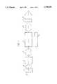
- FIG. 1is a block diagram of an intracavity modulated pulsed laser in accordance with one form of the present invention.
- FIG. 2illustrates the relationship between a conventional flashlamp pump pulse and a burst output which may be produced therefrom in accordance with the present invention.
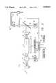
- FIG. 3is a block diagram of an intracavity modulated pulsed laser in accordance with a preferred form of the invention.
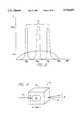
- FIG. 4is an illustration of an acousto-optical Q-switch in accordance with a preferred form of the present invention.
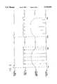
- FIG. 5is a timing diagram illustrating the relationship between flashlamp triggering, RF signal gating, flashlamp discharge, and laser output in an intracavity modulated pulsed laser in accordance with a preferred form of the present invention.
- FIGS. 6(a) and 6(b)illustrate how output sub-pulse peak powers are controlled by varying the modulation frequency of an intracavity modulated pulsed laser to achieve compatibility with a fiber optic delivery system having a given power density damage threshold (DT).
- DTpower density damage threshold
- FIG. 6(a)illustrates a low energy flashlamp pump pulse and a multi-pulsed burst laser output which may be produced therefrom
- FIG. 6(b)illustrates a high energy flashlamp pump pulse and a multi-pulsed burst laser output which may produced therefrom.
- FIG. 7is an illustration of an energy monitor in accordance with a preferred form of the present invention.
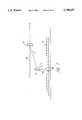
- FIG. 8is an illustration of a laser head embodying a preferred form of the present invention.
- FIG. 9is a block diagram of a frequency doubled intracavity modulated pulsed laser in accordance with the present invention.
- FIGS. 10(a)-(d)provide an illustration of several exemplary laser outputs which may be generated using a laser in accordance with one form of the present invention.
- FIG. 11is a flowchart illustrating the sequence of functions performed by a microprocessor in controlling an intracavity modulated pulsed laser in accordance with a preferred form of the present invention.
- FIG. 12is a block diagram of an intracavity modulated pulsed laser employing a fluorescence feedback circuit in accordance with the present invention.
- FIG. 13illustrates how sub-pulse peak powers are controlled using the fluorescence feedback circuit illustrated in FIG. 12.
- FIG. 14is an illustration of a control panel of an intracavity modulated pulsed laser in accordance with a preferred form of the present invention.
- FIG. 1is a block diagram of an intracavity modulated pulsed laser 1 in accordance with the present invention.
- the laser 1comprises an amplification medium 2, a pulsed pumping source 4, a modulator 6, a totally reflective mirror 8, and a partially reflective mirror 10.
- the amplification medium 2is disposed along an optical axis 12 between the two mirrors 8 and 10, and the pulsed pumping source 4, which may comprise, for example, a conventional flashlamp, is disposed adjacent the amplification medium 2 for delivering pulses of pump energy to the amplification medium 2 and exciting the atoms which comprise the amplification medium 2 to elevated quantum-mechanical energy levels.
- the modulator 6which may comprise for example an acousto-optical Q-switch or a saturable absorber dye, is also disposed along the optical axis 12 between the mirrors 8 and 10.
- the modulator 6functions to reduce stimulated emissions within the amplification medium (i.e. to minimize lasing or amplification of the beam 14 as it travels within the amplification medium) by disrupting the oscillation of the beam 14 between the mirrors 8 and 10. This process is commonly referred to as switching the quality or "Q" of a laser oscillator.
- the modulator 6also functions to increase the Q of the laser 1 at predetermined intervals within each pulse of energy generated by the pulsed pumping source 4, thus causing oscillation and amplification of the beam 14 at each such interval.
- the amplification medium 2 of the intracavity modulated pulsed laser 1comprises a standard, 1% neodymium doped, yttrium aluminum garnet rod (Nd:YAG rod) measuring 5 mm in diameter and 80 mm in length.
- Nd:YAG rodstandard, 1% neodymium doped, yttrium aluminum garnet rod measuring 5 mm in diameter and 80 mm in length.
- the dimensions of the Nd:YAG rodwill vary, however, depending upon the average power output and depending upon the particular beam diameter which is desired from the laser 1.
- Nd:YAG rods of the type describedmay be purchased from any one of a number of laser component distributors including Lightning Optical of Tarpon Springs, Fla.
- ARanti-reflective
- the AR coatingmay be centered at any one of a number of wavelengths including, for example, 1.064 ⁇ m, 1.320 ⁇ m, and 1.440 ⁇ m, depending upon the anticipated field of use of the laser 1. Although testing is ongoing, the 1.064 ⁇ m and the 1.320 ⁇ m wavelengths have demonstrated utility in hard and soft tissue applications.
- the utilization of amplification mediums other than neodymium doped yttrium aluminum garnet crystalmay require the utilization of AR coatings centered at other wavelengths. For example, it might be desirable to coat the ends of an erbium doped yttrium aluminum garnet rod with an AR coating centered at 2.910 ⁇ m.
- Flashlamps of this typeare available from ILC, Inc., of Sunnyvale, Calif., and the ILC Model L7652 is preferred.
- the energy delivered to the Nd:YAG rod 2 by the flashlamp 4is controlled by a microprocessor 20 which is coupled to the flashlamp power source 22.
- the microprocessor 20may comprise, for example, an Intel Model 8031 with EEPROM, and as illustrated, the microprocessor 20 delivers two signals S1 and S2 to the flashlamp power source 22.
- the first signal S1controls the amount of energy which is delivered from the power source 22 to the flashlamp 4 and, in turn, the amount of energy which is delivered from the flashlamp 4 to the Nd:YAG rod 2.
- the second signal S2triggers the discharge of the flashlamp power source 22 and, thus, controls the timing or repetition rate of the pulses generated by the flashlamp 4.
- the beam modulator 6 of the intracavity modulated pulsed laser 1comprises an acousto-optical Q-switch 24.
- an acousto-optical Q-switchcomprising a lithium niobate (LiNbO 3 ) transducer 26 bonded to an SF10 glass crystal 28.
- Acousto-optical Q-switches of this typemay be purchased, for example, from Neos, Inc., of Melbourne, Fla. However, it should be noted that numerous other acousto-optical Q-switches, including standard quartz switches, may be utilized.
- the acoustic aperture of the crystal 28should match the diameter of the oscillating beam 14, it has been found that the acousto-optical Q-switch 24 operates more efficiently if a slightly smaller acoustic aperture is used.
- An acoustic aperture measuring 4 mm by 15 mmis presently preferred.
- the modulator 6is preferably driven at a frequency of 27.12 Mhz by a RF driver 26.
- RF driverscapable of sustaining a 27.12 Mhz drive frequency at 10 watts peak power are available, for example, from Neos, Inc., of Melbourne, Fla.
- the initial activation and gating of the RF driver 26is preferably controlled by the microprocessor 20. For example, as shown in FIG.
- the microprocessor 20delivers a trigger signal S2 (shown as waveform A) to the flashlamp 4 causing the flashlamp 4 to discharge a pump pulse 11, the microprocessor simultaneously delivers an RF driver signal S3 (shown as waveform B) to the RF driver 26 and the RF driver signal S3 switches (or gates) the RF driver ON and OFF at predetermined intervals during the period of the flashlamp pump pulse 11 (shown as waveform C) .
- the period of the flashlamp discharge pulse 11is approximately 100 ⁇ s
- the gating frequency of the RF driver signal S3is set between 10 kHz and 300 kHz.
- a laser output 15(shown as waveform D) comprising a multi-pulsed burst of between 2 and 50 sub-pulses is produced from each flashlamp pump pulse 11.
- the gating frequency of the RF driver signal S3is controlled by the microprocessor 20. More specifically, the microprocessor 20 determines an optimum gating frequency (or optimum gating intervals) based on preset peak power and gating information which is stored in its memory.
- the optimum gating frequency of the preferred embodimentis the frequency at which the peak power of the largest sub-pulse in a multi-pulsed burst attains a prescribed threshold level L1 just below the power density damage threshold level DT of a fiber optic delivery system 40 used in conjunction with the intracavity modulated pulsed laser 1.
- the gating frequency of signal S3need not remain constant over the duration of a flashlamp pump pulse.
- optimum gating intervalsmay be established such that the peak powers of the sub-pulses comprising each multi-pulsed burst do not exceed the damage threshold of an associated laser delivery system.
- the microprocessor 20will still be used to trigger the flashlamp pulse and turn on the RF driver.
- the gating of the RF driveri.e. the modulator
- the microprocessor 20is controlled through the microprocessor 20 by a real-time feedback circuit (described below with reference to FIGS. 12 and 13) which monitors the gain of the laser cavity.
- FIGS. 6(a) and 6(b)An exemplary relationship between the amount of pump pulse energy delivered by the flashlamp 4 to the Nd:YAG rod 2 and the optimum gating frequency of the RF driver signal S3 for use with a fiber optic delivery system having a given power density damage threshold DT is illustrated in FIGS. 6(a) and 6(b).
- a small pump pulsefor example, a 50 mJ pulse pump
- the frequency of the RF gating signal S3will be set by the microprocessor 20 to approximately 50 kHz. If on the other hand, as shown in FIG.
- a large pump pulsefor example, a 320 mJ pump pulse
- the frequency of the RF gating signal S3will be set by the microprocessor 20 to approximately 320 kHz.
- the optimum gating frequency of the RF driverwill be increased as the amount of energy contained in each pump pulse P1 is increased, and the optimum gating frequency of the RF driver will be decreased as the amount of energy contained in each pump pulse P1 is decreased. It follows that by reprogramming the microprocessor 20 compatibility between the intracavity modulated pulsed laser 1 and virtually any fiber optic delivery system 40 may be readily achieved.
- a beam energy monitor 27is utilized to measure the energy contained in each output burst 15 generated by the intracavity modulated pulsed laser 1 and to provide feedback to the microprocessor 20.
- Thisenables the microprocessor 20, in response to variations which may occur over time between anticipated laser output energies and actual laser output energies, to automatically adjust the amount of energy which is delivered from the flashlamp power source 22 to the flashlamp 4 at a given pump pulse energy setting.
- a presently preferred energy monitoris illustrated in FIGS. 7 and 8 and comprises a shallow angle beam splitter 29, which picks off roughly 4% of the laser output beam 15 forming a sampled beam 31, and directs the sampled beam 31 toward an alumina diffuser 33.
- the alumina diffuser 33diffuses the sampled beam 31 forming a diffused beam 35, and a portion of the diffused beam 35 passes through a hole 37 located in the base plate 39 of the laser head 41 and strikes a germanium diode 43.
- the germanium diode 43upon being struck by the diffused beam 35, generates a current which is proportional to the intensity of the diffused beam 35, and the generated current is integrated over time and digitized by an electronic integrator (not shown). It will be noted by those skilled in the art that in this fashion the laser output beam 15 is integrated spatially by the diffuser 33 and temporally by the electronic integrator.
- the resulting signal S4which is delivered to the microprocessor 20, is proportional to the laser output burst energy and is independent of pulsewidth and spatial variation.
- a control panel 30is provided for conveying information indicative of a desired laser output burst energy and a desired burst repetition rate to the microprocessor 20.
- the control panel 30is under the control of a second microprocessor (not shown), which is coupled to the control system microprocessor 20 by conventional means.
- the totally reflective mirror 8comprise a convex mirror 10 having a radius of curvature of approximately 50 cm
- the partially reflective mirrorcomprise a concave mirror having a radius of curvature of approximately 60 cm.
- the utilization of a concave/convex mirror arrangementminimizes variations in the diameter of the oscillating beam 14, as the amount of energy delivered to the Nd:YAG rod 2 by the flashlamp 4 increases. In doing so, the concave/convex mirror arrangement minimizes potential damage to the input face (not shown) of the optical fiber 34.
- the multi-layer dielectric V coatingmay be centered at any of a number of wavelengths, including 1.064 ⁇ m, 1.320 ⁇ m, and 1.440 ⁇ m. Further, for soft tissue applications, coatings centered at 1.064 ⁇ m and 1.320 ⁇ m have demonstrated utility, whereas for certain hard tissue applications, such as the vaporization of dental enamel, a coating centered at 1.320 ⁇ m is presently preferred. It should be noted, however, that the precise coating used will depend upon the particular amplification medium utilized by the system, and that for this reason the identification of particular preferred wavelengths is not intended to limit the scope of the invention in any way.
- the totally reflective mirror 8With respect to the reflectivity of the mirrors 8 and 10, it is presently preferred to coat the totally reflective mirror 8 with a multi-layer dielectric V coating having a reflectivity of 99.5% or better.
- the partially reflective mirrorshould be coated with a multi-layer dielectric V coating having a reflectivity of approximately 60% if a laser output beam 15 having a wavelength of 1.064 ⁇ m is desired, and a reflectivity of 90% if a laser output beam 15 having a wavelength of 1.320 ⁇ m is desired.
- the laser output beam 15is combined with a visible aiming beam 36 generated by a helium neon (HeNe) laser 38 or a diode laser (not shown) using a conventional beam combining mirror 42.
- a practitioner using the laser 1may merely direct the visible aiming beam 36 at that tissue area.
- FIG. 8which provides an illustration of a laser head 41 in accordance with a preferred form of the present invention, it is presently preferred to house the flashlamp 4 and the Nd:YAG rod 2 within an optical pump chamber 45 having a pair of optical openings 47 disposed along the optical axis 12 (shown in FIGS. 1 and 3).
- the optical pump chamber 45in addition to providing a housing for the Nd:YAG rod 2 and the flashlamp 4, provides a conventional coolant flow system 49 which receives coolant (e.g. water) from a cooling system (not shown) and delivers that coolant to the Nd:YAG rod 2 and the flashlamp 4.
- Optical pump chambers of the type disclosed hereinmay be purchased, for example, from Big Sky Laser in Bozeman, Mont.
- intracavity modulated pulsed laserssuch as those described above, will meet a number of needs in the fields of medicine and dentistry, as well as in numerous other fields and applications. Moreover, it is submitted that intracavity modulated pulsed lasers, such as those described above, will be found useful in any field or application which requires an efficient laser capable of delivering output pulses having increased or controllable peak powers.
- second harmonic beam generation or frequency doublingis the field of second harmonic beam generation or frequency doubling. More specifically, in laser systems second harmonic beam generation or frequency doubling may be achieved through the use of non-linear birefringent crystals. Further, the efficiency of conversion from a fundamental frequency to a second harmonic frequency is proportional to the power density of the fundamental beam and, therefore, the power of the second harmonic beam is proportional to the square of the power of the fundamental beam. Thus, to provide a practical laser device capable of generating a frequency doubled beam, it is necessary to use a laser source capable of generating a beam having a high power density.
- an E-O Q-switched lasercapable of producing high power laser output pulses provides the laser power source, and the output pulses generated by the E-O Q-switched laser are provided to and passed through a non-linear crystal.
- E-O Q-switched laser systemsit is quite difficult to control the power density of the output pulses generated by such a system and, therefore, difficult to utilize such a system with conventional fiber optic delivery systems.
- the peak powers of the sub-pulses comprising the output burstsmay be controlled and set to a level not exceeding the threshold of an associated fiber optic delivery system.
- FIG. 9An exemplary embodiment of an intracavity modulated pulsed laser 70 including a non-linear crystal 72 for frequency doubling is illustrated in FIG. 9.
- the intracavity modulated pulsed laser 70 illustrated in FIG. 9 and the intracavity modulated pulsed laser 1 illustrated in FIG. 3comprise virtually the same components and function in virtually the same manner; the only difference between the two systems being that the intracavity modulated pulsed laser 70 illustrated in FIG. 9 includes a non-linear crystal 72.
- the non-linear crystal 72may comprise a potassium-titanyl-phosphate (KTP) crystal manufactured by Litton Industries (Airtron Division) of Morris Plains, N.J.
- KTPpotassium-titanyl-phosphate
- the non-linear crystal 72functions to convert a multi-pulsed output burst generated by the laser 1 from a wavelength of 1.064 ⁇ m to a wavelength of 532 nm (i.e. to a multi-pulsed burst having a frequency in the green spectrum).
- an intracavity modulated pulsed laser 1as a source for a frequency doubled system provides at least one substantial advantage in addition to allowing the frequency doubled system to be readily used with conventional optical fiber delivery systems
- an intracavity modulated pulsed laser 1provides a means for generating a plurality of multi-pulsed output bursts, each comprising a plurality of sub-pulses having selected, uniform peak powers.
- the peak powers of the sub-pulses comprising a multi-pulsed output burstmay be controlled in accordance with the present invention by varying the gating frequency or gate triggering of the RF driver 26, it is possible to control the gating frequency or gate triggering of the RF driver 26 in such a fashion that the sub-pulses comprising each multi-pulsed burst output have not only controlled, but also, uniform peak powers.
- the relationships between a typical flashlamp pump pulse 80 and three representative laser outputs which may be produced there fromare illustrated in FIGS. 10(a)-(d). If the pump pulse illustrated in FIG.
- the laser output pulseis modulated by triggering the gating of the RF driver 26 at a constant frequency (i.e. by setting the gating frequency of the RF driver to a constant frequency), a laser output similar to the multi-pulsed burst illustrated in FIG. 10(c) will result.
- the laser outputis modulated by gating the RF driver 26 at a varying frequency during the duration of the pump pulse (i.e.
- a laser output similar to the multi-pulsed burst illustrated in FIG. 10(d)will result.
- the gating frequency of the RF driver 26over the duration of the pump pulse, it is possible to produce a multi-pulsed burst output comprising a plurality of sub-pulses having not only controllable, but also, uniform peak powers.
- the generation of sub-pulses having uniform peak powersis highly desirable, and the use of an intracavity modulated pulsed laser system in accordance with the present invention to be quite useful as a laser source for a frequency doubled laser system.
- the utility of the Nd:YAG laserhas already been demonstrated. Specifically, it has been found that for numerous applications the Nd:YAG laser can be a highly effective tool. In part, this is because the 1.064 ⁇ m beam which is produced by the Nd:YAG laser may be carried with minimal energy losses by standard optical fibers.
- the difficulty which has been encountered by prior art systems, however,is that those systems have been unable to maintain a high average power output, while at the same time delivering laser output pulses which have increased peak powers and may be transmitted using conventional fiber optic delivery systems. For this reason treatment, including tissue vaporization and ablation, using the systems of the prior art requires substantial time.
- an intracavity modulated pulsed lasermaintains a high average power output while at the same time providing laser output pulses having increased peak powers, tissue vaporization and ablation, for example, using an intracavity modulated pulsed laser proceeds at a much more rapid rate.
- the intracavity modulated pulsed laserdelivers multi-pulsed energy bursts to an area of tissue to be treated, thermal damage to adjacent tissues is minimized.
- Fiber optic delivery systems 40generally comprise a optical fiber 34 which is coupled to a standard SMA 905 connector 44 at one end, and which has a conventional laser hand piece 46 coupled to the other end.
- the connector 44is adapted to engage the fiber coupler 32 (shown in FIGS. 3 and 8) such that both the aiming beam 36 and the laser output beam 15 may be carried by the fiber 34 to the hand piece 46.
- Hand pieces 46are generally of one of two types, contact and non-contact.
- the beams 15 and 36are generally deflected at a prescribed angle and focused at a prescribed distance from the hand piece 46 by conventional means.
- a practitionermust only direct the visible aiming beam 36 toward a prescribed tissue area. Once this is accomplished, the laser 1 may be "fired", activated by depressing the "fire" switch 48.
- the beams 15 and 36will be delivered to a contact tip (not shown), and when the contact tip is placed in contact with a prescribed tissue area, the beams 15 and 36 will be delivered directly to that tissue area at the point of contact.
- the practitionermay commence firing the laser either prior to or after bring the contact tip into contact with a desired tissue area.
- the microprocessor 20will proceed through the steps set forth in FIG. 11. Specifically, the microprocessor 20 will perform an initialization step (100) by reading the mode setting, the output energy setting, and the flashlamp pulse repetition rate setting, all of which are manually entered by the operator.
- the mode settingdetermines whether a conventional pulsed laser output or a multi-pulsed burst output will be delivered by the intracavity modulated pulsed laser.
- the output energy settingdetermines the amount of energy which will be delivered by the laser 1 within each conventional output pulse or each multi-pulsed output burst (depending upon the mode setting).
- the flashlamp pulse repetition rate settingdetermines the number of flashlamp pulses per second which will be delivered by the flashlamp 4 to the Nd:YAG rod 2 during continuously repeated firings of the laser.
- the microprocessor 20will perform flashlamp energy calculation step (110). Specifically, the microprocessor calculates and sets the amount of energy to be delivered from the flashlamp power source 22 to the flashlamp 4. This calculation is performed based on information stored in a look-up table, which is stored in the memory of the microprocessor 20. The information in the look-up table is based on a correction factor which is determined based on the previous output energy setting and the actual amount of energy delivered by the laser 1 within each conventional output pulse or each multi-pulsed burst as the case may be. The actual amount of energy delivered by the laser 1 is measured by the energy monitor 27. In this fashion, the microprocessor 20 compensates for changes in laser efficiency which will occur over time.
- the microprocessor 20will set the firing mode of the laser (120) to a conventional or a multi-pulsed burst setting in accordance with previously read mode information.
- the microprocessor 20will wait to receive a fire signal from the fire switch 48 (130), and after receiving the fire signal from the fire switch 48, the microprocessor will trigger a flashlamp pulse (140). If the multi-pulsed burst output mode has been selected, the microprocessor 20 will set the optimum gating frequency, or gating sequence, of the RF driver signal S3 (150), and wait for a fire signal from the fire switch 48 (160).
- the microprocessor 20Upon receiving a fire signal from the fire switch 48, the microprocessor 20 will, as shown in FIG.
- the microprocessor 20will turn off the oscillation and gating of the modulator 6 (180). In either mode, the laser output energy will be measured by the energy monitor 27, and a signal 54 indicative of the laser output energy will be provided by the energy monitor 27 to the microprocessor 20 (190). The microprocessor 20 will then wait for one pulse period (step 200) and repeat the sequence.
- the gating of the RF driver signal S3may be controlled using a fluorescence feedback circuit.
- An intracavity modulated pulsed laser 80 incorporating a fluorescence feedback circuit 82, 84 and 86is illustrated in FIG. 12.
- the fluorescence feedback circuitmay comprise, for example, a germanium photo-electric cell 82 manufactured by Germanium Power Devices (part number GM5) of Andover, Mass.; a 1.06 ⁇ m narrow pass filter 84 manufactured by Corion (part number SD 4-1064-F) of Hollister, Mass.; and a comparator 86.
- the photo-electric cell 82is disposed within the pump chamber of the laser 80 adjacent (or, stated differently, in the vicinity of) the Nd:YAG rod 2.
- the narrow pass filter 84is mounted to the photo-electric cell in a conventional fashion, and the photo-electric cell 82 is electrically coupled to one input of the comparator 86 which, in turn, is electrically coupled to the microprocessor 20.
- the microprocessor 20triggers the flashlamp pulse discharges and commences the oscillation of the modulator 6 (i.e. enable the delivery of the RF driver signal S3 to the RF driver 26).
- the gating of the modulator 6 and, more particularly, the gating of the RF driver signal S3is controlled in real-time, through the microprocessor 20, by the fluorescence feedback circuit 82, 84, and 86 which monitors the gain of the laser cavity and delivers a signal S5 to the microprocessor 20 when the gain of the laser cavity reaches a prescribed level (i.e.
- the microprocessor 20Upon receiving the signal S5 from the comparator 86 (indicating that the gain of the laser cavity has reached a predetermined level) the microprocessor 20 will gate the signal S3 being provided to the RF driver 26 for a period on the order of 2 ⁇ s, and an output pulse (or sub-pulse, as the case may be) will be emitted by the laser 80. This process will continue over the duration of each pump pulse provided by the flashlamp 4, enabling the laser 80, in response to each pump pulse provided by the flashlamp 4, to produce a multi-pulsed output burst comprising a plurality of sub-pulses having predetermined, uniform peak powers.
- the microprocessor 20may be programmed to adjust the reference voltage V ref of the comparator 86 in a conventional fashion and, the microprocessor 20 may be used to select the gain value at which the signal S5 will be sent to the microprocessor 20 by the comparator 86.
- the function of the feedback circuit 82, 84 and 86may be explained as follows.
- the amplitude and width of a Q-switched pulse for a fixed laser cavity geometrydepends on the gain in the cavity and, for a fixed cavity geometry, the gain is dependent on the number of excited Nd ions in the Nd:YAG rod 2.
- the rate of spontaneous emission and fluorescence of the Nd:YAG rod 2are also proportional to the number of excited ions.
- the photo-electric cell 82generates a signal S7, i.e.
- V S7a voltage V S7 , which is proportional to the detected fluorescence of the ND:YAG rod 2.
- Signal S7is provided to one input of the comparator 86 and, when compared to a reference voltage V ref (determined by signal S6, which is provided to the comparator 86 through D/A converter 88), determines the output state of the comparator 86. For example, when voltage V S7 exceeds the reference voltage V ref , the output (Signal 5) will be high; and when voltage V S7 does not exceed the reference voltage V ref , the output (Signal S5) will be low.
- the modulator 6will be gated, i.e., the Q-switch will be opened for approximately 2 ⁇ s, and a pulse (or, more appropriately, a sub-pulse) will be emitted by the laser 80.
- the multi-pulsed bursts emitted by the laser 80will be highly uniform in amplitude and duration. This is so because the gain of the laser cavity will be essentially equal for each sub-pulse comprising the emitted multi-pulsed bursts.
- the microprocessor 20may set the peak power of each sub-pulse comprising a given output burst to virtually any desired level within the operating parameters of the system.
- the fluorescence feedback circuit 82, 84 and 86need not necessarily provide a gating signal S5 to the microprocessor 20.
- the gating signal S5might be provided directly to the RF driver 26.
- the microprocessorwould enable the RF driver 26 (i.e. commence the oscillation of the A-O Q-switch 24), but the gating of the oscillation of the A-O Q-switch would be controlled by the provision of the gating signal S5 directly to the RF driver 26.
- the desired laser output burst energy setting and flashlamp pulse repetition rate settingare conveyed to the microprocessor 20 by the control panel 30.
- the burst energy settingmay be adjusted by manipulating a pair of buttons 50 labeled (+) and (-) which are located just below the pulse energy display 52 on the control panel 30.
- the pulse repetition ratemay be adjusted by manipulating a pair of buttons 54 labeled (+) and (-) which are located just below the pulse repetition rate display 56 on the control panel 30.
- the multi-pulsed burst modemay be selected by depressing a button 58 labeled accordingly.
- the burst energy settingmay be set between 30 mJ and 320 mJ
- the flashlamp pulse repetition ratemay be set between 10 Hz and 100 Hz.
Landscapes
- Physics & Mathematics (AREA)
- Electromagnetism (AREA)
- Engineering & Computer Science (AREA)
- Plasma & Fusion (AREA)
- Optics & Photonics (AREA)
- Lasers (AREA)
Abstract
Description
TABLE 1 ______________________________________ APPLI- AVG RF CA- ENERGY RATE POWER GATING TION MODE (mJ) (Hz) (W) FREQUENCY ______________________________________ Incision Multi-pulsed 30-200 20-50 3-10 30-200 kHz Conventional 30-200 20-50 3-10 Off Exci- Multi-pulsed 30-200 20-50 3-10 30-200 kHz sion Conventional 30-200 20-50 3-10 Off Abla- Multi-pulsed 30-100 50-100 3-10 30-100 kHz tion Conventional 30-100 50-100 3-10 Off Coagu- Conventional 30-100 30-100 3-10 Off lation ______________________________________
TABLE 2 ______________________________________ RF AVG GATING APPLI- ENERGY RATE POWER FREQUENCY CATION MODE (mJ) (Hz) (W) (kHz) ______________________________________ Ablation Multi- 100-320 30-100 3-10 100-320 pulsed Ablation Conven- 200-320 30-100 6-10 Off tional ______________________________________
Claims (5)
Priority Applications (1)
| Application Number | Priority Date | Filing Date | Title |
|---|---|---|---|
| US08/597,998US5748655A (en) | 1992-09-25 | 1996-02-07 | Intracavity modulated pulsed laser and methods of using the same |
Applications Claiming Priority (3)
| Application Number | Priority Date | Filing Date | Title |
|---|---|---|---|
| US07/951,075US5390204A (en) | 1992-09-25 | 1992-09-25 | Intracavity modulated pulsed laser with a variably controllable modulation frequency |
| US08/350,951US5621745A (en) | 1992-09-25 | 1994-12-07 | Intracavity modulated pulsed laser and methods of using the same |
| US08/597,998US5748655A (en) | 1992-09-25 | 1996-02-07 | Intracavity modulated pulsed laser and methods of using the same |
Related Parent Applications (1)
| Application Number | Title | Priority Date | Filing Date |
|---|---|---|---|
| US08/350,951ContinuationUS5621745A (en) | 1992-09-25 | 1994-12-07 | Intracavity modulated pulsed laser and methods of using the same |
Publications (1)
| Publication Number | Publication Date |
|---|---|
| US5748655Atrue US5748655A (en) | 1998-05-05 |
Family
ID=25491230
Family Applications (4)
| Application Number | Title | Priority Date | Filing Date |
|---|---|---|---|
| US07/951,075Expired - LifetimeUS5390204A (en) | 1992-09-25 | 1992-09-25 | Intracavity modulated pulsed laser with a variably controllable modulation frequency |
| US08/350,951Expired - LifetimeUS5621745A (en) | 1992-09-25 | 1994-12-07 | Intracavity modulated pulsed laser and methods of using the same |
| US08/597,998Expired - LifetimeUS5748655A (en) | 1992-09-25 | 1996-02-07 | Intracavity modulated pulsed laser and methods of using the same |
| US08/768,250Expired - LifetimeUS5832013A (en) | 1992-09-25 | 1996-12-17 | Intracavity modulated pulsed laser and methods of using the same |
Family Applications Before (2)
| Application Number | Title | Priority Date | Filing Date |
|---|---|---|---|
| US07/951,075Expired - LifetimeUS5390204A (en) | 1992-09-25 | 1992-09-25 | Intracavity modulated pulsed laser with a variably controllable modulation frequency |
| US08/350,951Expired - LifetimeUS5621745A (en) | 1992-09-25 | 1994-12-07 | Intracavity modulated pulsed laser and methods of using the same |
Family Applications After (1)
| Application Number | Title | Priority Date | Filing Date |
|---|---|---|---|
| US08/768,250Expired - LifetimeUS5832013A (en) | 1992-09-25 | 1996-12-17 | Intracavity modulated pulsed laser and methods of using the same |
Country Status (6)
| Country | Link |
|---|---|
| US (4) | US5390204A (en) |
| EP (1) | EP0662260A4 (en) |
| JP (1) | JPH08501903A (en) |
| AU (1) | AU4932193A (en) |
| DE (1) | DE662260T1 (en) |
| WO (1) | WO1994008372A1 (en) |
Cited By (17)
| Publication number | Priority date | Publication date | Assignee | Title |
|---|---|---|---|---|
| WO2000076037A1 (en)* | 1999-06-07 | 2000-12-14 | Coherent, Inc. | Pulsed diode-pumped solid-state laser |
| US6587483B2 (en)* | 1999-12-04 | 2003-07-01 | Carl Zeiss Jena Gmbh | Q-switched solid state laser with adjustable pulse length |
| US20040264517A1 (en)* | 2003-06-30 | 2004-12-30 | Yunlong Sun | Laser pulse picking employing controlled AOM loading |
| US20050100062A1 (en)* | 2003-06-30 | 2005-05-12 | Electro Scientific Industries, Inc. | High energy pulse suppression method |
| US7859660B2 (en)* | 2001-03-20 | 2010-12-28 | Kaiser Optical Systems | Laser indication light configuration |
| US20110196355A1 (en)* | 2008-11-18 | 2011-08-11 | Precise Light Surgical, Inc. | Flash vaporization surgical systems |
| US9036247B2 (en) | 2011-07-05 | 2015-05-19 | Electro Scientific Industries, Inc. | Systems and methods for providing temperature stability of acousto-optic beam deflectors and acousto-optic modulators during use |
| US9246303B1 (en) | 2014-10-31 | 2016-01-26 | Raytheon Company | Method and apparatus for temporally concentrating pump power to support generation of high peak-power pulse bursts or other time-varying laser output waveforms |
| US9871339B1 (en) | 2016-12-15 | 2018-01-16 | Raytheon Company | Laser transmitter for generating a coherent laser output signal with reduced self-phase modulation and method |
| US11253317B2 (en) | 2017-03-20 | 2022-02-22 | Precise Light Surgical, Inc. | Soft tissue selective ablation surgical systems |
| US11684421B2 (en) | 2006-08-24 | 2023-06-27 | Pipstek, Llc | Dental and medical treatments and procedures |
| US11701202B2 (en) | 2013-06-26 | 2023-07-18 | Sonendo, Inc. | Apparatus and methods for filling teeth and root canals |
| USD997355S1 (en) | 2020-10-07 | 2023-08-29 | Sonendo, Inc. | Dental treatment instrument |
| US11918432B2 (en) | 2006-04-20 | 2024-03-05 | Sonendo, Inc. | Apparatus and methods for treating root canals of teeth |
| US12114924B2 (en) | 2006-08-24 | 2024-10-15 | Pipstek, Llc | Treatment system and method |
| US12186151B2 (en) | 2010-10-21 | 2025-01-07 | Sonendo, Inc. | Apparatus, methods, and compositions for endodontic treatments |
| US12268565B2 (en) | 2009-11-13 | 2025-04-08 | Sonendo, Inc. | Liquid jet apparatus and methods for dental treatments |
Families Citing this family (69)
| Publication number | Priority date | Publication date | Assignee | Title |
|---|---|---|---|---|
| US6106546A (en)* | 1988-10-11 | 2000-08-22 | The General Hospital Corporation | Inducing vasodilation |
| US5390204A (en)* | 1992-09-25 | 1995-02-14 | Incisive Technologies, Inc. | Intracavity modulated pulsed laser with a variably controllable modulation frequency |
| US5375132A (en)* | 1993-05-05 | 1994-12-20 | Coherent, Inc. | Solid state laser with interleaved output |
| DE4401917C2 (en)* | 1994-01-24 | 1998-02-12 | Med Laserzentrum Luebeck Gmbh | Device for generating laser pulses with pulse lengths in the range of a few microseconds |
| DE4444636A1 (en)* | 1994-12-15 | 1996-06-20 | Sepp Gunther | Weapon system for a glare laser |
| US6135995A (en)* | 1995-09-26 | 2000-10-24 | Coherent, Inc. | Electronically pulsed laser system |
| US5721749A (en)* | 1996-01-30 | 1998-02-24 | Trw Inc. | Laser pulse profile control by modulating relaxation oscillations |
| US5818601A (en)* | 1996-10-04 | 1998-10-06 | The United States Of America As Represented By The Secretary Of The Navy | Wavelength independent optical probe |
| US5724373A (en)* | 1996-11-15 | 1998-03-03 | Hewlett-Packard Company | Microphotonic acousto-optic tunable laser |
| SE9702175D0 (en)* | 1997-06-06 | 1997-06-06 | Geotronics Ab | A laser |
| DE19731699A1 (en)* | 1997-07-23 | 1999-01-28 | Kaltenbach & Voigt | Pulsed light source |
| US6132037A (en)* | 1997-09-03 | 2000-10-17 | Bartolome; Jordi | Storage container for inkjet cartridges having cleaning means and a method for storing inkjet cartridges |
| DE19740824A1 (en)* | 1997-09-17 | 1999-03-18 | Laser & Med Tech Gmbh | Channel production device for heart muscle tissue |
| US6055674A (en)* | 1997-12-08 | 2000-05-02 | Sara Lee Corporation | Panty pantyhose combination garment and method for forming same |
| US5991929A (en)* | 1997-12-08 | 1999-11-30 | Sara Lee Corporation | Panty pantyhose combination garment and method for forming same |
| US6091749A (en)* | 1998-02-26 | 2000-07-18 | Trw Inc. | Laser system controller |
| US6074384A (en)* | 1998-03-06 | 2000-06-13 | Plc Medical Systems, Inc. | Endocardial laser revascularization with single laser pulses |
| US6213998B1 (en) | 1998-04-02 | 2001-04-10 | Vanderbilt University | Laser surgical cutting probe and system |
| AUPP281698A0 (en)* | 1998-04-06 | 1998-04-30 | Lions Eye Institute Of Western Australia Incorporated, The | Method and apparatus for laser ablation |
| US6110195A (en)* | 1998-06-01 | 2000-08-29 | Altralight, Inc. | Method and apparatus for surgical and dermatological treatment by multi-wavelength laser light |
| US6130900A (en)* | 1999-03-05 | 2000-10-10 | Coherent, Inc. | Pulsed intracavity frequency-converted solid-state laser with long-pulse simulation |
| US6879606B1 (en) | 1999-07-26 | 2005-04-12 | Laser Vision Technologies | Intracavity doubled laser |
| AU5042400A (en)* | 1999-07-26 | 2001-02-13 | Laser Vision Technologies | Intracavity doubled laser |
| WO2001052371A1 (en)* | 2000-01-10 | 2001-07-19 | California Institute Of Technology | Optical pulse synthesis using brillouin selective sideband amplification |
| US6490299B1 (en) | 2000-07-20 | 2002-12-03 | Troitski | Method and laser system for generating laser radiation of specific temporal shape for production of high quality laser-induced damage images |
| CA2314691C (en) | 2000-07-28 | 2011-04-26 | Andreas Mandelis | Method and apparatus for detection of defects in teeth |
| DE10055179B4 (en)* | 2000-11-08 | 2006-03-02 | Lisa Laser Products Ohg Fuhrberg & Teichmann | Operation of a laser device, in particular for surgical applications |
| US7567596B2 (en) | 2001-01-30 | 2009-07-28 | Board Of Trustees Of Michigan State University | Control system and apparatus for use with ultra-fast laser |
| WO2002061799A2 (en)* | 2001-01-30 | 2002-08-08 | Board Of Trustees Operating Michigan State University | Control system and apparatus for use with laser excitation or ionization |
| US7973936B2 (en) | 2001-01-30 | 2011-07-05 | Board Of Trustees Of Michigan State University | Control system and apparatus for use with ultra-fast laser |
| US7450618B2 (en)* | 2001-01-30 | 2008-11-11 | Board Of Trustees Operating Michigan State University | Laser system using ultrashort laser pulses |
| US7583710B2 (en)* | 2001-01-30 | 2009-09-01 | Board Of Trustees Operating Michigan State University | Laser and environmental monitoring system |
| US8208505B2 (en) | 2001-01-30 | 2012-06-26 | Board Of Trustees Of Michigan State University | Laser system employing harmonic generation |
| US7609731B2 (en)* | 2001-01-30 | 2009-10-27 | Board Of Trustees Operating Michigan State University | Laser system using ultra-short laser pulses |
| JP3838064B2 (en)* | 2001-09-28 | 2006-10-25 | 松下電器産業株式会社 | Laser control method |
| JP3903761B2 (en)* | 2001-10-10 | 2007-04-11 | 株式会社日立製作所 | Laser annealing method and laser annealing apparatus |
| JP2005518255A (en)* | 2002-02-22 | 2005-06-23 | レーザースコープ | Photoselective vaporization therapy and system for gynecological treatment |
| US7088749B2 (en)* | 2003-01-06 | 2006-08-08 | Miyachi Unitek Corporation | Green welding laser |
| US7103074B2 (en)* | 2003-06-03 | 2006-09-05 | Corporation For Laser Optics Research | Laser video projection system and method with anti-piracy feature |
| US7130321B2 (en)* | 2003-10-09 | 2006-10-31 | Coherent, Inc. | Intracavity frequency-tripled CW laser with traveling-wave ring-resonator |
| US7352784B2 (en)* | 2004-07-20 | 2008-04-01 | Jds Uniphase Corporation | Laser burst boosting method and apparatus |
| US8633437B2 (en) | 2005-02-14 | 2014-01-21 | Board Of Trustees Of Michigan State University | Ultra-fast laser system |
| DE102005007241B4 (en)* | 2005-02-17 | 2007-05-31 | Hydrometer Gmbh | Flowmeter |
| US20060289411A1 (en)* | 2005-06-24 | 2006-12-28 | New Wave Research | Laser system with multiple operating modes and work station using same |
| EP1957959A2 (en) | 2005-11-30 | 2008-08-20 | Board of Trustees of Michigan State University | Laser based identification of molecular characteristics |
| EP2001388A2 (en)* | 2006-02-02 | 2008-12-17 | Releaf Medical Ltd. | Shock-wave generating device, such as for the treatment of calcific aortic stenosis |
| US9018562B2 (en) | 2006-04-10 | 2015-04-28 | Board Of Trustees Of Michigan State University | Laser material processing system |
| US7460566B2 (en)* | 2006-05-02 | 2008-12-02 | Northrop Grumman Corporation | Laser power reduction without mode change |
| US20080033411A1 (en)* | 2006-07-14 | 2008-02-07 | Biolase Technology, Inc. | High efficiency electromagnetic laser energy cutting device |
| FR2906091B1 (en)* | 2006-09-19 | 2010-04-16 | Lokki S A | LASER APPARATUS WITH PULSE EMISSION |
| EP2229730B1 (en)* | 2007-12-06 | 2013-04-24 | Freescale Semiconductor, Inc. | Semiconductor device and apparatus including semiconductor device |
| EP2232653B1 (en) | 2007-12-21 | 2013-03-27 | Board of Trustees of Michigan State University | Phase control in ultrashort pulse lasers by a deformable mirror in the pulse stretcher |
| US20100027571A1 (en)* | 2008-07-31 | 2010-02-04 | Murdoch Keith M | Stabilized near-infrared laser |
| EP2211430A3 (en) | 2009-01-23 | 2015-05-27 | Board of Trustees of Michigan State University | Laser autocorrelation system |
| WO2010141128A2 (en) | 2009-03-05 | 2010-12-09 | Board Of Trustees Of Michigan State University | Laser amplification system |
| WO2010111604A1 (en) | 2009-03-27 | 2010-09-30 | Ams Research Corporation | Laser modulation for coagulation |
| US20120055909A1 (en)* | 2009-05-15 | 2012-03-08 | Hideaki Miyake | Method of laser-welding and method of manufacturing battery including the same |
| US8696653B2 (en)* | 2009-10-02 | 2014-04-15 | Cardiofocus, Inc. | Cardiac ablation system with pulsed aiming light |
| US8630322B2 (en) | 2010-03-01 | 2014-01-14 | Board Of Trustees Of Michigan State University | Laser system for output manipulation |
| WO2013103794A1 (en)* | 2012-01-06 | 2013-07-11 | Dentsply International Inc. | System and method for performing endodontic procedures with lasers |
| US10109976B2 (en)* | 2014-01-21 | 2018-10-23 | Cornell University | Divided pulse lasers |
| US10107660B2 (en)* | 2014-07-21 | 2018-10-23 | Apator Miitors Aps | Flow conduit insert |
| US10893906B2 (en) | 2016-10-04 | 2021-01-19 | Boston Scientific Scimed, Inc. | Tailored laser pulses for surgical applications |
| DE102018200811B4 (en)* | 2018-01-18 | 2020-02-20 | Trumpf Laser Gmbh | Method and laser system for generating amplified pulse on demand output laser pulses |
| CN108471043A (en)* | 2018-04-27 | 2018-08-31 | 国科世纪激光技术(天津)有限公司 | Acousto-optic Q modulation solid state laser and control method |
| US12279812B2 (en) | 2019-08-05 | 2025-04-22 | Gyrus Acmi, Inc. | Laser fiber varying lateral position and intensity |
| CN110474227B (en)* | 2019-08-16 | 2021-01-26 | 清华大学 | A short pulse laser system and control method based on Burst mode |
| KR102221082B1 (en)* | 2020-02-13 | 2021-02-26 | (주)엘트라글로벌 | Method of generating multi laser pulse using multi Q-switching and Apparatus of generating multi laser pulse |
| EP4194135B1 (en)* | 2020-08-07 | 2025-05-14 | Amada Co., Ltd. | Laser oscillator, laser processing machine, and stimulated raman scattering inhibition method |
Citations (2)
| Publication number | Priority date | Publication date | Assignee | Title |
|---|---|---|---|---|
| US5151909A (en)* | 1990-10-16 | 1992-09-29 | Laserscope | Frequency doubled solid state laser having programmable pump power modes and method for controllable lasers |
| US5390204A (en)* | 1992-09-25 | 1995-02-14 | Incisive Technologies, Inc. | Intracavity modulated pulsed laser with a variably controllable modulation frequency |
Family Cites Families (43)
| Publication number | Priority date | Publication date | Assignee | Title |
|---|---|---|---|---|
| US3513409A (en)* | 1966-12-15 | 1970-05-19 | United Aircraft Corp | Q-spoiling of lasers using two dye cells |
| US3962558A (en)* | 1971-03-29 | 1976-06-08 | Ernst Kocher | Method and apparatus for drilling watch jewels or other workpieces by means of laser beams |
| US3725812A (en)* | 1971-05-26 | 1973-04-03 | Texas Instruments Inc | Laser system moving electronically selectable gain |
| US3884236A (en)* | 1971-10-28 | 1975-05-20 | Mikhail M Krasnov | Method of glaucoma treatment |
| US3821510A (en)* | 1973-02-22 | 1974-06-28 | H Muncheryan | Hand held laser instrumentation device |
| US3878478A (en)* | 1973-07-25 | 1975-04-15 | Eastman Kodak Co | Mode-locking giant pulse lasers |
| US4105952A (en)* | 1976-05-21 | 1978-08-08 | John Tulip | High repetition rate pulsed laser discharge system |
| US4273109A (en)* | 1976-07-06 | 1981-06-16 | Cavitron Corporation | Fiber optic light delivery apparatus and medical instrument utilizing same |
| JPS5576646A (en)* | 1978-12-04 | 1980-06-09 | Morita Mfg | Teeth decaying preventive device by laser ray irradiation |
| US4316476A (en)* | 1979-04-07 | 1982-02-23 | Heinz Merges | Flat curler to curl or undulate hair |
| CA1147048A (en)* | 1979-06-14 | 1983-05-24 | Herb J.J. Seguin | High power laser and cathode structure therefor |
| US4337442A (en)* | 1980-03-28 | 1982-06-29 | Electro Scientific Industries, Inc. | First laser pulse amplitude modulation |
| US4412330A (en)* | 1981-04-16 | 1983-10-25 | Electro Scientific Industries, Inc. | Q-Switched laser with stable output and method of making the same |
| JPS587235A (en)* | 1981-07-07 | 1983-01-17 | 住友電気工業株式会社 | laser scalpel |
| JPS6041928Y2 (en)* | 1981-09-04 | 1985-12-21 | 株式会社モリタ製作所 | Contra-angle handpiece for dental treatment using laser light |
| US4784135A (en)* | 1982-12-09 | 1988-11-15 | International Business Machines Corporation | Far ultraviolet surgical and dental procedures |
| US4672969A (en)* | 1983-10-06 | 1987-06-16 | Sonomo Corporation | Laser healing method |
| US4521194A (en)* | 1983-12-22 | 1985-06-04 | Myers William D | Method for removing incipient carious lesions and/or stain from teeth |
| CA1262757A (en)* | 1985-04-25 | 1989-11-07 | Richard M. Dwyer | Method and apparatus for laser surgery |
| US4818230A (en)* | 1985-12-13 | 1989-04-04 | Myers William D | Method for removing decay from teeth |
| FR2597745A1 (en)* | 1986-04-24 | 1987-10-30 | Levy Guy | Process for connection between two materials, by fusion obtained by means of a laser beam, applicable in dentistry |
| US4826431A (en)* | 1986-06-12 | 1989-05-02 | Kabushiki Kaisha Morita Seisakusho | Medical laser handpiece |
| US5048034A (en)* | 1986-11-20 | 1991-09-10 | Carl Zeiss Stiftung | Long wavelength NdYAG laser |
| US4719639B1 (en)* | 1987-01-08 | 1994-06-28 | Boreal Laser Inc | Carbon dioxide slab laser |
| US4874315A (en)* | 1987-02-19 | 1989-10-17 | Eastman Dental Center | Method for bonding of restorative materials to a tooth |
| DE3850330T2 (en)* | 1987-02-24 | 1994-10-13 | Nippon Steel Corp | DEVICE FOR FINISHING A ROLL WITH IMPULSE LASER. |
| US4852567A (en)* | 1988-01-21 | 1989-08-01 | C. R. Bard, Inc. | Laser tipped catheter |
| US4877401A (en)* | 1988-03-09 | 1989-10-31 | University Of Utah | Method of preventing tooth decay by laser beam irradiation and chemical treatment |
| IL87015A (en)* | 1988-07-06 | 1992-11-15 | Zvi Teumim Stone | Laser apparatus for periodontal treatment |
| US5037421A (en)* | 1989-10-06 | 1991-08-06 | Coherent, Inc., Medical Group | Mid-infrared laser arthroscopic procedure |
| US4940411A (en)* | 1988-08-25 | 1990-07-10 | American Dental Laser, Inc. | Dental laser method |
| US5055048A (en)* | 1988-08-25 | 1991-10-08 | American Dental Laser, Inc. | Dental laser assembly |
| US5020995A (en)* | 1989-01-18 | 1991-06-04 | Guy Levy | Surgical treatment method and instrument |
| US5092773A (en)* | 1989-01-18 | 1992-03-03 | Endo Technic Corporation | Method and apparatus for filling a tooth canal |
| US4930901A (en)* | 1988-12-23 | 1990-06-05 | Electro Scientific Industries, Inc. | Method of and apparatus for modulating a laser beam |
| US5128949A (en)* | 1989-05-31 | 1992-07-07 | The United States Of America As Represented By The Administrator Of The National Aeronautics And Space Administration | Method and circuit for controlling the evolution time interval of a laser output pulse |
| US5018152A (en)* | 1989-09-07 | 1991-05-21 | Spectra-Physics, Inc. | Apparatus for controlling pulse energy in a Q-switched laser system |
| US4979180A (en)* | 1989-11-24 | 1990-12-18 | Muncheryan Arthur M | Modular interchangeable laser system |
| US5001717A (en)* | 1990-03-19 | 1991-03-19 | Mcdonnell Douglas Corporation | Cavity dump laser controller |
| US5059200A (en)* | 1990-04-06 | 1991-10-22 | John Tulip | Laser lithotripsy |
| US5197074A (en)* | 1991-12-26 | 1993-03-23 | Electro Scientific Industries, Inc. | Multi-function intra-resonator loss modulator and method of operating same |
| US5291505A (en)* | 1993-01-21 | 1994-03-01 | Hughes Aircraft Company | Active energy control for diode pumped laser systems using pulsewidth modulation |
| US5339323A (en)* | 1993-04-30 | 1994-08-16 | Lumonics Corporation | Laser system for controlling emitted pulse energy |
- 1992
- 1992-09-25USUS07/951,075patent/US5390204A/ennot_activeExpired - Lifetime
- 1993
- 1993-09-22JPJP6509150Apatent/JPH08501903A/enactivePending
- 1993-09-22EPEP93921717Apatent/EP0662260A4/ennot_activeWithdrawn
- 1993-09-22AUAU49321/93Apatent/AU4932193A/ennot_activeAbandoned
- 1993-09-22WOPCT/US1993/008994patent/WO1994008372A1/ennot_activeApplication Discontinuation
- 1993-09-22DEDE0662260Tpatent/DE662260T1/enactivePending
- 1994
- 1994-12-07USUS08/350,951patent/US5621745A/ennot_activeExpired - Lifetime
- 1996
- 1996-02-07USUS08/597,998patent/US5748655A/ennot_activeExpired - Lifetime
- 1996-12-17USUS08/768,250patent/US5832013A/ennot_activeExpired - Lifetime
Patent Citations (2)
| Publication number | Priority date | Publication date | Assignee | Title |
|---|---|---|---|---|
| US5151909A (en)* | 1990-10-16 | 1992-09-29 | Laserscope | Frequency doubled solid state laser having programmable pump power modes and method for controllable lasers |
| US5390204A (en)* | 1992-09-25 | 1995-02-14 | Incisive Technologies, Inc. | Intracavity modulated pulsed laser with a variably controllable modulation frequency |
Cited By (27)
| Publication number | Priority date | Publication date | Assignee | Title |
|---|---|---|---|---|
| US6418154B1 (en) | 1999-06-07 | 2002-07-09 | Coherent, Inc. | Pulsed diode-pumped solid-state laser |
| WO2000076037A1 (en)* | 1999-06-07 | 2000-12-14 | Coherent, Inc. | Pulsed diode-pumped solid-state laser |
| US6587483B2 (en)* | 1999-12-04 | 2003-07-01 | Carl Zeiss Jena Gmbh | Q-switched solid state laser with adjustable pulse length |
| US7859660B2 (en)* | 2001-03-20 | 2010-12-28 | Kaiser Optical Systems | Laser indication light configuration |
| US8081668B2 (en) | 2003-06-30 | 2011-12-20 | Electro Scientific Industries, Inc. | High energy pulse suppression method |
| US7616669B2 (en) | 2003-06-30 | 2009-11-10 | Electro Scientific Industries, Inc. | High energy pulse suppression method |
| US20100046561A1 (en)* | 2003-06-30 | 2010-02-25 | Electro Scientific Industries, Inc. | High energy pulse suppression method |
| US20050100062A1 (en)* | 2003-06-30 | 2005-05-12 | Electro Scientific Industries, Inc. | High energy pulse suppression method |
| US6947454B2 (en)* | 2003-06-30 | 2005-09-20 | Electro Scientific Industries, Inc. | Laser pulse picking employing controlled AOM loading |
| US20040264517A1 (en)* | 2003-06-30 | 2004-12-30 | Yunlong Sun | Laser pulse picking employing controlled AOM loading |
| US11918432B2 (en) | 2006-04-20 | 2024-03-05 | Sonendo, Inc. | Apparatus and methods for treating root canals of teeth |
| US12213731B2 (en) | 2006-08-24 | 2025-02-04 | Pipstek, Llc | Dental and medical treatments and procedures |
| US11684421B2 (en) | 2006-08-24 | 2023-06-27 | Pipstek, Llc | Dental and medical treatments and procedures |
| US12114924B2 (en) | 2006-08-24 | 2024-10-15 | Pipstek, Llc | Treatment system and method |
| US8881735B2 (en) | 2008-11-18 | 2014-11-11 | Precise Light Surgical, Inc. | Flash vaporization surgical systems and method |
| US9844410B2 (en) | 2008-11-18 | 2017-12-19 | Precise Light Surgical, Inc. | Flash vaporization surgical systems |
| US20110196355A1 (en)* | 2008-11-18 | 2011-08-11 | Precise Light Surgical, Inc. | Flash vaporization surgical systems |
| US12268565B2 (en) | 2009-11-13 | 2025-04-08 | Sonendo, Inc. | Liquid jet apparatus and methods for dental treatments |
| US9622819B2 (en) | 2010-04-22 | 2017-04-18 | Precise Light Surgical, Inc. | Flash vaporization surgical systems |
| US12186151B2 (en) | 2010-10-21 | 2025-01-07 | Sonendo, Inc. | Apparatus, methods, and compositions for endodontic treatments |
| US9036247B2 (en) | 2011-07-05 | 2015-05-19 | Electro Scientific Industries, Inc. | Systems and methods for providing temperature stability of acousto-optic beam deflectors and acousto-optic modulators during use |
| US11701202B2 (en) | 2013-06-26 | 2023-07-18 | Sonendo, Inc. | Apparatus and methods for filling teeth and root canals |
| US9246303B1 (en) | 2014-10-31 | 2016-01-26 | Raytheon Company | Method and apparatus for temporally concentrating pump power to support generation of high peak-power pulse bursts or other time-varying laser output waveforms |
| US10186828B2 (en) | 2016-12-15 | 2019-01-22 | Raytheon Company | Laser transmitter for generating a coherent laser output signal with reduced self-phase modulation and method |
| US9871339B1 (en) | 2016-12-15 | 2018-01-16 | Raytheon Company | Laser transmitter for generating a coherent laser output signal with reduced self-phase modulation and method |
| US11253317B2 (en) | 2017-03-20 | 2022-02-22 | Precise Light Surgical, Inc. | Soft tissue selective ablation surgical systems |
| USD997355S1 (en) | 2020-10-07 | 2023-08-29 | Sonendo, Inc. | Dental treatment instrument |
Also Published As
| Publication number | Publication date |
|---|---|
| AU4932193A (en) | 1994-04-26 |
| WO1994008372A1 (en) | 1994-04-14 |
| US5832013A (en) | 1998-11-03 |
| EP0662260A1 (en) | 1995-07-12 |
| EP0662260A4 (en) | 1997-07-02 |
| US5621745A (en) | 1997-04-15 |
| DE662260T1 (en) | 1995-12-14 |
| JPH08501903A (en) | 1996-02-27 |
| US5390204A (en) | 1995-02-14 |
Similar Documents
| Publication | Publication Date | Title |
|---|---|---|
| US5748655A (en) | Intracavity modulated pulsed laser and methods of using the same | |
| US7769059B2 (en) | High power Q-switched laser for soft tissue ablation | |
| US5381431A (en) | Picosecond Q-switched microlasers | |
| US5287380A (en) | Method and apparatus for generating long output pulses from flashlamp-excited lasers | |
| US5982789A (en) | Pulsed laser with passive stabilization | |
| US6090102A (en) | Short pulse mid-infrared laser source for surgery | |
| US4914663A (en) | Generation of short high peak power pulses from an injection mode-locked Q-switched laser oscillator | |
| US6683893B2 (en) | Q-switching method for pulse train generation | |
| EP0807326B1 (en) | Improved method for producing long pulses of laser radiation | |
| US6654391B2 (en) | Method for operating Q-switched lasers with intracavity frequency conversion | |
| US5561678A (en) | Time-sharing laser | |
| US6188704B1 (en) | Diode-pumped laser drive | |
| US5271025A (en) | Mode-locked upconversion laser source | |
| WO1997031411A1 (en) | Stabilisation of a pulsed laser | |
| EP0904615B1 (en) | Pulsed laser with passive stabilization | |
| Li et al. | Self-frequency doubling of a laser diode array pumped Q-switched NYAB laser | |
| US20240285342A1 (en) | Suppressing relaxation oscillations for lithotripsy lasers | |
| US3628044A (en) | Second harmonic laser | |
| RU2573619C1 (en) | CONTROL METHOD OF PULSE GENERATION MODE OF LASER EMISSION IN LASER UNIT BASED ON SOLID-STATE LASER ON Nd:YAG CRYSTAL WITH DIODE PUMPING OF ACTIVE MEDIUM | |
| Larat et al. | High-repetition-rate solid state laser for space communications | |
| Di Lazzaro et al. | Design of a self-injected unstable cavity Nd: YAG Laser | |
| KR20250111569A (en) | Laser apparatus for medical | |
| RU2176839C1 (en) | Method for intracavity parametric light maser | |
| Pinto et al. | Suppression of relaxation oscillations in flash-pumped 2-μm lasers | |
| Skorczakowski et al. | 2.94 µm electro-optically Q-switched Er: YAG laser with high output energy |
Legal Events
| Date | Code | Title | Description |
|---|---|---|---|
| AS | Assignment | Owner name:AMERICAN DENTAL TECHNOLOGIES, INC., MICHIGAN Free format text:ASSIGNMENT OF ASSIGNORS INTEREST;ASSIGNOR:INCISIVE TECHNOLOGIES, INC.;REEL/FRAME:007894/0447 Effective date:19941121 | |
| AS | Assignment | Owner name:NBD BANK, MICHIGAN Free format text:ASSIGNMENT OF ASSIGNORS INTEREST;ASSIGNOR:AMERICAN DENTAL TECHNOLOGIES, INC.;REEL/FRAME:009605/0387 Effective date:19980926 | |
| REMI | Maintenance fee reminder mailed | ||
| REIN | Reinstatement after maintenance fee payment confirmed | ||
| LAPS | Lapse for failure to pay maintenance fees | Free format text:PATENT EXPIRED FOR FAILURE TO PAY MAINTENANCE FEES (ORIGINAL EVENT CODE: EXP.); ENTITY STATUS OF PATENT OWNER: SMALL ENTITY | |
| FP | Lapsed due to failure to pay maintenance fee | Effective date:20020505 | |
| AS | Assignment | Owner name:BL ACQUISITION CORP., CALIFORNIA Free format text:ASSIGNMENT OF ASSIGNORS INTEREST;ASSIGNOR:AMERICAN MEDICAL TECHNOLOGIES, INC.;REEL/FRAME:014321/0001 Effective date:20030521 | |
| FEPP | Fee payment procedure | Free format text:PETITION RELATED TO MAINTENANCE FEES GRANTED (ORIGINAL EVENT CODE: PMFG); ENTITY STATUS OF PATENT OWNER: SMALL ENTITY | |
| AS | Assignment | Owner name:AMERICAN DENTAL TECHNOLOGIES, INC., TEXAS Free format text:ASSIGNMENT OF ASSIGNORS INTEREST;ASSIGNOR:BANKONE, NA;REEL/FRAME:014788/0160 Effective date:20030516 | |
| AS | Assignment | Owner name:AMERICAN DENTAL TECHNOLOGIES, INC., TEXAS Free format text:ASSIGNMENT RELEASE;ASSIGNOR:BANK ONE, N.A. [SUCCESSOR BY MERGER TO NBD BANK];REEL/FRAME:015027/0879 Effective date:20030516 | |
| FPAY | Fee payment | Year of fee payment:4 | |
| SULP | Surcharge for late payment | ||
| PRDP | Patent reinstated due to the acceptance of a late maintenance fee | Effective date:20040324 | |
| STCF | Information on status: patent grant | Free format text:PATENTED CASE | |
| FPAY | Fee payment | Year of fee payment:8 | |
| FPAY | Fee payment | Year of fee payment:12 | |
| AS | Assignment | Owner name:MIDCAP FINANCIAL, LLC, AS AGENT AND AS A LENDER, M Free format text:SECURITY AGREEMENT;ASSIGNOR:BIOLASE TECHNOLOGY, INC.;REEL/FRAME:024900/0550 Effective date:20100527 | |
| AS | Assignment | Owner name:HENRY SCHEIN, INC., NEW YORK Free format text:SECURITY AGREEMENT;ASSIGNORS:BIOLASE TECHNOLOGY, INC.;BL ACQUISITION CORP.;BL ACQUISITION II INC.;REEL/FRAME:025066/0488 Effective date:20100923 | |
| AS | Assignment | Owner name:BIOLASE TECHNOLOGY, INC., CALIFORNIA Free format text:SECURITY AGREEMENT PAYOFF;ASSIGNOR:MIDCAP FINANCIAL, LLC, AGENT AND AS LENDER;REEL/FRAME:026285/0666 Effective date:20110208 | |
| AS | Assignment | Owner name:BL ACQUISITION II INC., CALIFORNIA Free format text:RELEASE BY SECURED PARTY;ASSIGNOR:HENRY SCHEIN, INC.;REEL/FRAME:028184/0218 Effective date:20120412 Owner name:BIOLASE TECHNOLOGY, INC., CALIFORNIA Free format text:RELEASE BY SECURED PARTY;ASSIGNOR:HENRY SCHEIN, INC.;REEL/FRAME:028184/0218 Effective date:20120412 Owner name:BL ACQUISTION CORP., CALIFORNIA Free format text:RELEASE BY SECURED PARTY;ASSIGNOR:HENRY SCHEIN, INC.;REEL/FRAME:028184/0218 Effective date:20120412 | |
| AS | Assignment | Owner name:BIOLASE, INC., CALIFORNIA Free format text:CHANGE OF NAME;ASSIGNOR:BIOLASE TECHNOLOGY, INC.;REEL/FRAME:029328/0096 Effective date:20120511 |