US5748221A - Apparatus for colorimetry gloss and registration feedback in a color printing machine - Google Patents
Apparatus for colorimetry gloss and registration feedback in a color printing machineDownload PDFInfo
- Publication number
- US5748221A US5748221AUS08/551,306US55130695AUS5748221AUS 5748221 AUS5748221 AUS 5748221AUS 55130695 AUS55130695 AUS 55130695AUS 5748221 AUS5748221 AUS 5748221A
- Authority
- US
- United States
- Prior art keywords
- detector
- image
- determining
- gloss
- generating
- Prior art date
- Legal status (The legal status is an assumption and is not a legal conclusion. Google has not performed a legal analysis and makes no representation as to the accuracy of the status listed.)
- Expired - Lifetime
Links
- 238000007639printingMethods0.000titleclaimsabstractdescription31
- 238000004737colorimetric analysisMethods0.000titledescription6
- 238000000034methodMethods0.000claimsabstractdescription17
- 238000000926separation methodMethods0.000claimsabstractdescription13
- 239000003086colorantSubstances0.000claimsabstractdescription12
- 239000000758substrateSubstances0.000claimsabstractdescription9
- 238000012360testing methodMethods0.000claimsdescription15
- 230000003287optical effectEffects0.000claimsdescription8
- 238000001914filtrationMethods0.000claimsdescription4
- 238000005259measurementMethods0.000abstractdescription19
- 238000003384imaging methodMethods0.000abstractdescription9
- 238000012937correctionMethods0.000abstractdescription4
- 239000000463materialSubstances0.000description12
- 108091008695photoreceptorsProteins0.000description12
- 238000012546transferMethods0.000description12
- 239000000843powderSubstances0.000description8
- 229910021417amorphous siliconInorganic materials0.000description6
- 239000002245particleSubstances0.000description6
- 239000002131composite materialSubstances0.000description5
- 238000001514detection methodMethods0.000description5
- 238000011161developmentMethods0.000description5
- 238000005516engineering processMethods0.000description5
- 238000005286illuminationMethods0.000description5
- 238000013507mappingMethods0.000description5
- 230000008569processEffects0.000description5
- 230000002441reversible effectEffects0.000description4
- 238000013528artificial neural networkMethods0.000description3
- 238000006243chemical reactionMethods0.000description3
- 238000010586diagramMethods0.000description3
- 230000006870functionEffects0.000description3
- 230000010354integrationEffects0.000description3
- 238000012986modificationMethods0.000description3
- 230000004048modificationEffects0.000description3
- 238000003491arrayMethods0.000description2
- 230000008901benefitEffects0.000description2
- 238000004140cleaningMethods0.000description2
- 230000001419dependent effectEffects0.000description2
- 239000000428dustSubstances0.000description2
- 230000000694effectsEffects0.000description2
- 239000008187granular materialSubstances0.000description2
- 238000003908quality control methodMethods0.000description2
- 230000035945sensitivityEffects0.000description2
- 238000009966trimmingMethods0.000description2
- 239000002699waste materialSubstances0.000description2
- 239000004642PolyimideSubstances0.000description1
- YJVBLROMQZEFPA-UHFFFAOYSA-Lacid red 26Chemical compound[Na+].[Na+].CC1=CC(C)=CC=C1N=NC1=C(O)C(S([O-])(=O)=O)=CC2=CC(S([O-])(=O)=O)=CC=C12YJVBLROMQZEFPA-UHFFFAOYSA-L0.000description1
- 230000009471actionEffects0.000description1
- 238000013459approachMethods0.000description1
- 238000012550auditMethods0.000description1
- 239000003990capacitorSubstances0.000description1
- 239000011248coating agentSubstances0.000description1
- 238000000576coating methodMethods0.000description1
- 239000000470constituentSubstances0.000description1
- 238000011109contaminationMethods0.000description1
- 229910021419crystalline siliconInorganic materials0.000description1
- 230000001351cycling effectEffects0.000description1
- 230000007547defectEffects0.000description1
- 230000002939deleterious effectEffects0.000description1
- 238000013461designMethods0.000description1
- 238000007599dischargingMethods0.000description1
- 238000009826distributionMethods0.000description1
- 229910052736halogenInorganic materials0.000description1
- 150000002500ionsChemical class0.000description1
- 238000004519manufacturing processMethods0.000description1
- 239000011159matrix materialSubstances0.000description1
- 239000002991molded plasticSubstances0.000description1
- 230000008450motivationEffects0.000description1
- 229920001721polyimidePolymers0.000description1
- 230000005855radiationEffects0.000description1
- 230000003252repetitive effectEffects0.000description1
- 238000001228spectrumMethods0.000description1
- 239000007921spraySubstances0.000description1
- 238000000859sublimationMethods0.000description1
- 230000008022sublimationEffects0.000description1
- 230000001960triggered effectEffects0.000description1
Images


Classifications
- H—ELECTRICITY
- H04—ELECTRIC COMMUNICATION TECHNIQUE
- H04N—PICTORIAL COMMUNICATION, e.g. TELEVISION
- H04N1/00—Scanning, transmission or reproduction of documents or the like, e.g. facsimile transmission; Details thereof
- H04N1/46—Colour picture communication systems
- H04N1/50—Picture reproducers
- H04N1/506—Reproducing the colour component signals picture-sequentially, e.g. with reproducing heads spaced apart from one another in the subscanning direction
- G—PHYSICS
- G03—PHOTOGRAPHY; CINEMATOGRAPHY; ANALOGOUS TECHNIQUES USING WAVES OTHER THAN OPTICAL WAVES; ELECTROGRAPHY; HOLOGRAPHY
- G03G—ELECTROGRAPHY; ELECTROPHOTOGRAPHY; MAGNETOGRAPHY
- G03G2215/00—Apparatus for electrophotographic processes
- G03G2215/01—Apparatus for electrophotographic processes for producing multicoloured copies
- G03G2215/0167—Apparatus for electrophotographic processes for producing multicoloured copies single electrographic recording member
- G03G2215/0174—Apparatus for electrophotographic processes for producing multicoloured copies single electrographic recording member plural rotations of recording member to produce multicoloured copy
Definitions
- This inventionrelates generally to the calibration, registration and gloss control of color images in a color image output terminal (IOT), and more particularly concerns an improved color image alignment and image quality control system utilizing an improved multifunction sensing and feedback device in full color printing machines including electrophotographic, ink jet, thermal transfer, sublimation and other types.
- IOTcolor image output terminal
- electrophotographic typewill be most used as example in the following diclosure; however, any of the others would have been suitable.
- a photoconductive memberis charged to a substantially uniform potential so as to sensitize the surface thereof.
- the charged portion of the photoconductive memberis exposed to a light image of an original document being reproduced. Exposure of the charged photoconductive member selectively dissipates the charges thereon in the irradiated areas.
- the latent imageis developed by bringing a developer material into contact therewith.
- the developer materialcomprises toner particles adhering triboelectrically to carrier granules.
- the toner particlesare attracted from the carrier granules to the latent image forming a toner powder image on the photoconductive member.
- the toner powder imageis then transferred from the photoconductive member to a copy sheet.
- the toner particlesare heated to permanently affix the powder image to the copy sheet.
- the foregoinggenerally describes a typical black and white electrophotographic printing machine.
- an architecturewhich comprises a plurality of image forming stations.
- One example of the plural image forming station architectureutilizes an image on image system in which the photoreceptive member is recharged, reimaged and developed for each color separation. This charging, imaging, developing and recharging reimaging and developing is done in a single revolution of the photoreceptor in so-called single pass machines, while multipass architectures form each color separation with a single charge, recharge system and imager and multiple developers, one for each color.
- the single pass architectureoffers a potential for high throughput.
- a single device which can determine colorimetric, gloss and registration values from test imagesis highly desireable in multicolor document output terminals.
- Murayama et al.employ a marking system with a detector for measuring alignment errors and mechanically move individual color printers to correct misalignment.
- Color printers that employ marks produced by each of the constituent colors in juxtaposition with each otherenable correction of lateral and longitudinal relative position, skew and magnification.
- Measurement of the position of each of the registration marks and the test patches for gloss and colorimetric valuesmay be accomplished by illuminating the marks and employing a lens to collect the diffusely reflected light to image the reflection on photodetectors or photodetector arrays.
- the illuminationis in the visible wavelength.
- the diffuse reflection from the marksmust be significantly different from its background. It is desirable therefore,
- PatenteeOhigashi et al.
- PatenteeKatsumata et al.
- PatenteeKamas et al.
- U.S. Pat. No. 5,160,946 to Hwangdiscloses a registration system for an electrophotographic printing machine which forms registration indicia at a first transfer station and utilizes the formed indicia to register the image at subsequent transfer stations.
- U.S. Pat. No. 4,965,597discloses a color image recording apparatus which superimposes a plurality of different color images on one another to form a composite image. Registration marks are formed on a recording medium and are sensed at each station to assure a clear and accurate superimposed image. A sensor senses one or both edges of a recording medium to note image deviations caused by transport to enable compensation thereof.
- U.S. Pat. No. 4,916,547discloses a color image forming apparatus which produces a single composite color image on a paper.
- the paperis transported by a belt and the composite color image is formed by transferring image components of different colors to the paper in register with each other.
- the apparatusreduces positional deviation of a plurality of image components of different colors by sensing signals on a surface of the transfer belt outside a paper region.
- the sensorsenses arriving pattern images and corrects for unaligned images by calculating a deviation amount and adjusting a timing signal accordingly.
- U.S. Pat. No. 4,804,979discloses a single pass color printer/plotter having four separate microprocessor-based print stations, each for printing a different color image for superimposition with one another to form a full color image.
- the printerincludes a registration system where each print station monitors registration marks to correct for media variations.
- Each print stationincludes optical sensors that monitor the marks printed on the media edge to synchronize the printing and align the images properly.
- spectrophotometers and colorimeterssuch as the Minolta® CM-2002 spectrophotometer and an X-Rite® DTP51 Colorimeter are available to perform various colorimetric and gloss tests, however these devices are slow and require significant set-up time.
- a high speed multi-function sensorfor a multi-color printing machine.
- the apparatuscomprises a first detector for determining a colorimetric value of an image and generating a signal indicative thereof, a second detector for determining a gloss value of an image and generating a signal indicative thereof and a third detector for determining a registration value between a plurality of color separations in the image and generating a signal indicative thereof.
- the fourth detectoris a timing (or windowing) mark detector to initiate the above-indicated measurements.
- a color electrophotographic printing machinecomprising a full color electrophotographic printing machine having an intregral device for determining colorimetric, gloss, and registration values for an image.
- the devicecomprises a first detector for determining a colorimetric value of an image and generating a signal indicative thereof, a second detector for determining a gloss value of an image and generating a signal indicative thereof and a third detector for determining a registration value between a plurality of color separations in the image and generating a signal indicative thereof.
- a fourth detectoris a timing (or windowing) mark detector to initiate the above-indicated measurements.
- a method for determining colorimetric, gloss, and registration mark values in a full color electrophotographic printing machinecomprises illuminating a test pattern with a light source, detecting the reflected signal from the target pattern, filtering the detected signal with a red, green, and blue filter respectively and converting the filtered signals to a colorimetric (L* a* b*) value for the specific colorant in the printing machine. Said conversion depends on dedicated calibration procedures.
- FIG. 1shows the sensor pattern arrangement for using the present invention
- FIG. 2illustrates a side elevational view of a first embodiment of the combination sensor of the invention herein;
- FIG. 3illustrates an end elevational view of the FIG. 1 sensor
- FIG. 4illustrates a side elevational view of a second embodiment of the combination sensor of the invention herein;
- FIG. 5illustrates a plan view of the FIG. 4 embodiment illustrating the combination calibration shutter dust cover
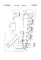
- FIG. 6is a schematic diagram of a four color image output terminal utilizing the device of the present invention.
- FIG. 7illustates a block diagram of an example of control circuitry for the sensor.
- This inventionrelates to an imaging system which is used to produce color output in a single revolution or pass of a photoreceptor belt. It will be understood, however, that it is not intended to limit the invention to the embodiment disclosed. On the contrary, it is intended to cover all alternatives, modifications and equivalents as may be included within the spirit and scope of the invention as defined by the appended claims, including a multiple pass color process system, and a single or multiple pass highlight color system.
- the printing machine of the present inventionuses a charge retentive surface in the form of an Active Matrix (AMAT) photoreceptor belt 10 supported for movement in the direction indicated by arrow 12, for advancing sequentially through the various xerographic process stations.
- the beltis entrained about a drive roller 14, tension rollers 16 and fixed roller 18 and the roller 14 is operatively connected to a drive motor 20 for effecting movement of the belt through the xerographic stations.
- AMATActive Matrix
- a portion of belt 10passes through charging station A where a corona generating device, indicated generally by the reference numeral 22, charges the photoconductive surface of belt 10 to a relative high, substantially uniform, preferably negative potential.
- the charged portion of photoconductive surfaceis advanced through an imaging station B.
- the uniformly charged belt 10is exposed to a laser based output scanning device 24 which causes the charge retentive surface to be discharged in accordance with the output from the scanning device.
- the scanning deviceis a laser Raster Output Scanner (ROS).
- ROSRaster Output Scanner
- the ROScould be replaced by other xerographic exposure devices such as LED arrays.
- the photoreceptorwhich is initially charged to a voltage V 0 , undergoes dark decay to a level V ddp equal to about -500 volts. When exposed at the exposure station B it is discharged to V background equal to about -50 volts. Thus after exposure, the photoreceptor contains a monopolar voltage profile of high and low voltages, the former corresponding to charged areas and the latter corresponding to discharged or background areas.
- a magnetic brush developer structureindicated generally by the reference numeral 26 advances insulative magnetic brush (IMB) material 31 into contact with the electrostatic latent image.
- the development structure 26comprises a plurality of magnetic brush roller members. These magnetic brush rollers present, for example, charged black toner material to the image areas for development thereof. Appropriate developer biasing is accomplished via power supply 32.
- a corona recharge device 36 having a high output current vs. control surface voltage (I/V) characteristic slopeis employed for raising the voltage level of both the toned and untoned areas on the photoreceptor to a substantially uniform level.
- the recharging device 36serves to recharge the photoreceptor to a predetermined level.
- a second exposure or imaging device 38which may comprise a laser based input and/or output structure is utilized for selectively discharging the photoreceptor on toned areas and/or bare areas, pursuant to the image to be developed with the second color developer.
- the photoreceptorcontains toned and untoned areas at relatively high voltage levels and toned and untoned areas at relatively low voltage, levels. These low voltage areas represent image areas which are developed using discharged area development (DAD).
- DADdischarged area development
- a negatively charged, developer material 40comprising color toner is employed.
- the tonerwhich by way of example may be yellow, is contained in a developer housing structure 42 disposed at a second developer station D and is presented to the latent images on the photoreceptor by a of a magnetic brush developer roller.
- a power supply(not shown) serves to electrically bias the developer structure to a level effective to develop the DAD image areas with negatively charged yellow toner particles 40.
- a negative pre-transfer dicorotron member 50is provided to condition the toner for effective transfer to a substrate using positive corona discharge.
- a sheet of support material 52is moved into contact with the toner images at transfer station G.
- the sheet of support materialis advanced to transfer station G by conventional sheet feeding apparatus, not shown.
- the sheet feeding apparatusincludes a feed roll contacting the uppermost sheet of a stack copy sheets. The feed rolls rotate so as to advance the uppermost sheet from stack into a chute which directs the advancing sheet of support material into contact with photoconductive surface of belt 10 in a timed sequence so that the toner powder image developed thereon contacts the advancing sheet of support material at transfer station G.
- Transfer station Gincludes a transfer dicorotron 54 which sprays positive ions onto the backside of sheet 52. This attracts the negatively charged toner powder images from the belt 10 to sheet 52.
- a detack dicorotron 56is provided for facilitating stripping of the sheets from the belt 10.
- Fusing station Hincludes a fuser assembly, indicated generally by the reference numeral 60, which permanently affixes the transferred powder image to sheet 52.
- fuser assembly 60comprises a heated fuser roller 62 and a backup or pressure roller 64.
- Sheet 52passes between fuser roller 62 and backup roller 64 with the toner powder image contacting fuser roller 62.
- a chuteguides the advancing sheets 52 to a catch tray, not shown, for subsequent removal from the printing machine by the operator.
- the sensor device 100 of the present inventionis located in the paper path between the fuser assembly 60 and the catch tray.
- the fused target substrate 52is passed by the sensor and a sample image is scanned for calibration purposes as described below.
- the residual toner particles carried by the non-image areas on the photoconductive surfaceare removed therefrom. These particles are removed at cleaning station H using a cleaning brush structure contained in a housing 66.
- FIGS. 1-5 inclusivefor clarity and convenience, the schemes will be described in terms of chevron marks and bicell detectors such as those described in U.S. Pat. No. 5,287,162, the pertinent portions of which are herein incorporated by reference.
- the main feature of the sensor deviceis the color measurement.
- the color-to-color registrationenables the sensor to be used either in place of a MOB (Mark-on-Belt) sensor, or whenever the toners are indistinguishable from each other in infrared lighting (the MOB illumination source).
- MOBMark-on-Belt
- the gloss measurementis an additional feature which helps control another important quality characteristic of the printer output.
- the conceptual basis of the designis to measure color by imaging a part of an illuminated color patch on three amorphous silicon detector elements after filtering with red, green, and blue materials.
- the technologyis akin to that of color input scanners.
- the detector outputscan be used as densitometric values to assure color constancy.
- Calibration of the resulting instrument outputs against measurement by laboratory colorimeters taken over a large sample of patches made by the toners of the printer of interestallows mapping to absolute color coordinates (such as L*a*b*).
- a mobile dust cover 170(FIG. 5) is used to prevent excessive contamination and doubles in its function in presenting a white sample to the device for drift correction purposes.
- Color-to-color registration errorsare measured by the same chevron mark technology successfully employed in MOB sensors. The only difference is that the operation is performed in the visible range and the same illumination, optics and detector chip as in the color measurement are used. Bi-cell detectors 140,142, 144, 146 (FIG. 1) on the chip perform this function. To improve measurement contrast red, green and blue filters are also used on these bi-cells. The red-filtered photodiodes are used to measure the relative positions of the cyan and black registration marks; while the green-filtered photodiodes are used to measure the relative positions of the magenta and black registration marks; and the blue-filtered photodiodes are used to measure the relative positions of the yellow and black registration marks.
- the rows of bicell photodiodes, groups 160,are arranged to align with the optical center in order to eliminate any deleterious effects of barreling or pin-cushioning.
- the auxiliary blue-filtered bicell photodiodes, group 140,are not so aligned, and as a result, the image of straight registration marks may be subject to curvature. So long as this effect is understood, the auxiliary blue-filtered bicells 140 can be advantageously used for extending the lateral capture range in coarse registration procedures and for obtaining larger signals from yellow marks.
- Glossis measured at a 45 degree specular angle by means of a green-filtered amorphous silicon detector 107. In the present configuration no optical elements are included so that some diffuse reflection may add to the signal. However, this error should be tolerable.
- the reflectance values measured by the sensor elementsare mapped to corresponding laboratory spectrophotometer CIELAB values (e.g., for D50/2 deg) by use of neural networks.
- the factory calibrationproceeds as follows. A number of color patches are printed using the toners from the target printer family using a printer representative of that family. The color of the patches are selected so as to adequately represent the volume and surface of the printer's color gamut. The CIELAB coordinates of the patches need to be measured once using the spectrophotometer and the data stored. These same patches are then measured by means of the sensor of this invention. The data set from the sensor, together with the corresponding spectrophotometer results, is then used to create a mapping between the sensor's rgb space to the CIELAB color space.
- the fidelity of the mapping on several test patchesis verified and evaluated for the specific toners used in the printer. Once a valid network is built for a specific set of toners, it can be exercised with any test patch printed using those toners to produce absolute measurements (L*a*b*).
- the parameters representing the mappingare then stored in permanent memory onboard the sensor for field use. Depending upon manufacturing tolerances and desired color accuracies, this factory calibration procedure can be followed for each sensor. Alternatively, this procedure can be followed using data from sensors selected according to quality control audits of a batch build. The parameters obtained from factory calibration of the selected sensors could then be stored permanently onboard the remaining sensors in the batch (as well as those that were tested).
- the neural networkis the most general and can be implemented with data which are not organized in a rectangular grid.
- these networksare computationally intensive not only during their learning phase but also in their application phase. Therefore, a possible course of action is to use the learned neural network to generate data with inputs on a rectangular mesh so that mapping in real use can be performed by straight forward linear interpolation. Under these conditions, the rectangular mesh would also be created once during factory calibration.
- Amorphous siliconwas chosen because of its low cost for the rather large detector area (9 ⁇ 9 mm), because of its low dark reverse current and because of its insensitivity to infrared radiation. Crystalline silicon could also be used with the appropriate filtering. (Note that amorphous silicon also needs a detector trimming filter to eliminate unwanted effects of infrared sensitivity).
- the sensor 100 locationis downstream of the fuser as shown in FIG. 6.
- the subject inventioncan be produced at a very low cost and it can compete with much more expensive instruments because it is calibrated against the specific toners with which it is going to be used in a printer and can be mass produced.
- FIG. 7illustates a block diagram of an example of control circuitry for the sensor.
- the operation of the detector 100 for colorimetry and registration measurementis based on imaging the diffuse reflection of the illuminated target 52 onto a detector at 1:1 magnification to take advantage of symmetry in minimizing image defects.
- the essential geometry of the colorimetry and registration detector chipis shown in the drawing of FIG. 1. It occupies an 8 mm ⁇ 8 mm area. A description of the functions are as follows:
- Colorimetryis performed by the four large rectangular areas near the top of the figure.
- the patternlies within the 4 mm radius field of view with the increasing area dedicated to weaker signals (i.e., the blue pattern 130 is the largest at 7.4 mm ⁇ 1.1 mm, the green pattern 132 is 6.6 mm ⁇ 0.75 mm, and the red signal 134 is expected to be the strongest and therefore allocated the smallest area of 5.8 mm ⁇ 0.75 mm).
- the black-filtered photodiode 136has an output which continuously measures dark reverse current irrespective of whether the lamp is ON or OFF. It must be assumed, of course that the dark reverse current density is the same in the four elements 130,132, 134 and 136. This allows keeping the lamp ON for color measurements only.
- the output of the black pattern 136can be used to compensate for drift of temperature dependent parameters through feedback control. Filters such as Brewer Science polyimides are suitable for use such as: Red 101, Green 103, Blue EXP93006 (aka, ExpBlue#4).
- Registration detectionis performed using segmented bi-cells 140, 142, 144, 146 arranged in a chevron pattern.
- the blue channelbeing the weakest expected signal, has additional surface dedicated to it.
- Each of the smaller bi-cell halves 142, 144,146are 0.7 mm ⁇ 0.4 mm.
- the larger blue bi-cell halves 140are 1.9 mm ⁇ 0.4 mm.
- the timing mark and image artifact detectoris the horizontal green bicell pattern 150 in the middle of the sensor and measures 2.4 mm ⁇ 0.29 mm. It is used to facilitate the windowing problem by detecting separation marks placed between the color patches. This approach makes it possible to accurately locate the target patch with reduced resource requirements. Specifically, the colorimetric measurements would be triggered a specific time delay after a timing mark, such as a line across the process direction approximately 0.29 mm thick and more than 2.4 mm wide, is detected. The motivation for following this procedure is that the noise within a half-tone color sample patch places a restriction on its minimal size even if the neasurement system does not. In the interest of measurement efficiency, provision is made to provide sufficient sample sizes in a layout of test samples which does not waste space.
- a third mark 162is a triangular relief in the blue colorimetry pattern 130. This mark also indicates the sensor's optical center. The marks are used during assembly of the chip on the electronics board. The chips will use either standard 24 pin DIPs or chip-on-board technology. With this later technology, the amorphous silicon die is directly mounted and electrically connected to a printed circuit substrate.
- Gloss detectionis performed by a separate chip.
- a green filter coating(such as Brewer 103) can be applied to limit the signal to the wavelength distribution characterizing the human eye.
- the detectorhas an active rectangular area of 6.4 mm ⁇ 3.2 mm and is shown in FIGS. 2 and 4 as 107.
- FIG. 2illustrates a general arrangement of the sensor with the illumination source 102, the optics 104, the detectors 106 and the trimming filter 108.
- the illuminationis provided by a tungsten-halogen lamp (ie. Sylvania 1990).
- the lamp filamentwas located two inches from the target and without intervening optics. This resulted in good performance but insufficient light to take a reading in 0.25 inches of travel in a 1000 mm/sec printer of a target patch with an optical density greater than 2.
- FIG. 4In order to increase the lighting, a second embodiment as illustrated in FIG. 4 was developed.
- the lamp 102was placed at 1.5 inches from the target, a curved reflector 103 was placed behind it, and a light diffuser 105 was added in the light path 109.
- the 0.25 inch square measurement patchcan be achieved at 1000 mm/sec. This measurement area was selected as a minimum in order to avoid noise due the halftone pattern. However, longer patches are undesirable due to the waste of space.
- the lenses usedare 6 mm in diameter which can be adjusted in size depending on the application. Two configurations of lenses are suggested: a) two plano-convex lenses assembled belly-to-belly; b) two doublet achromat lenses assembled belly-to-belly.
- An aperture washeris located between the lenses.
- the aperturesare holes 3 or 4.5 mm in diameter in a 0.5 mm thick black washer.
- Lensescan be a molded plastic material. All internal light passages are round and have sharp tooth threads 110 to minimize stray light paths. After the lenses the light crosses an infrared filter 108 which acts as a detector trimmer. Its task is to eliminate the narrow region of sensitivity of the amorphous silicon in the infrared region of the spectrum.
- An example of a suitable filteris an ORIEL 51980 (a BG38 style) filter.
- the sensormay also be used for optical density grayscale detection and gloss detection in black and white printers.
- the optical densitycan be determined by utilizing the green channel of the sensor to measure the density of the black toner or ink.
- a method and apparatus for measuring colorimetric, gloss and registration data on a substrate exiting a printing machineA detector using a series of red, green, and blue filters collects image data and maps the collected data to absolute color coordinates specific to the colorants used in the printing machine. Gloss measurements are made using the same instrument. Registration data between the various color separations is also obtained and feedback delivered to the various imaging modules. The detector allows on the fly data to be obtained and machine specific corrections to be made.
Landscapes
- Engineering & Computer Science (AREA)
- Multimedia (AREA)
- Signal Processing (AREA)
- Color Electrophotography (AREA)
- Spectrometry And Color Measurement (AREA)
- Facsimile Image Signal Circuits (AREA)
Abstract
Description
Claims (13)
Priority Applications (4)
| Application Number | Priority Date | Filing Date | Title |
|---|---|---|---|
| US08/551,306US5748221A (en) | 1995-11-01 | 1995-11-01 | Apparatus for colorimetry gloss and registration feedback in a color printing machine |
| JP8282530AJPH09218097A (en) | 1995-11-01 | 1996-10-24 | Multi-function sensor, full color electrophotographic printing machine and method for determining color value, glossiness value and register adjustment mark value |
| BR9605347ABR9605347A (en) | 1995-11-01 | 1996-10-29 | Multifunction sensor for measuring colorimetric brightness and registration values in a printed image Process for determining collimeric brightness and registration mark values for an image printed on a substrate and full color electrophotographic printing machine |
| EP96307860AEP0772345A3 (en) | 1995-11-01 | 1996-10-30 | Apparatus for colorimetry, gloss and registration feedback in a color printing machine |
Applications Claiming Priority (1)
| Application Number | Priority Date | Filing Date | Title |
|---|---|---|---|
| US08/551,306US5748221A (en) | 1995-11-01 | 1995-11-01 | Apparatus for colorimetry gloss and registration feedback in a color printing machine |
Publications (1)
| Publication Number | Publication Date |
|---|---|
| US5748221Atrue US5748221A (en) | 1998-05-05 |
Family
ID=24200728
Family Applications (1)
| Application Number | Title | Priority Date | Filing Date |
|---|---|---|---|
| US08/551,306Expired - LifetimeUS5748221A (en) | 1995-11-01 | 1995-11-01 | Apparatus for colorimetry gloss and registration feedback in a color printing machine |
Country Status (4)
| Country | Link |
|---|---|
| US (1) | US5748221A (en) |
| EP (1) | EP0772345A3 (en) |
| JP (1) | JPH09218097A (en) |
| BR (1) | BR9605347A (en) |
Cited By (85)
| Publication number | Priority date | Publication date | Assignee | Title |
|---|---|---|---|---|
| US6052195A (en)* | 1998-05-22 | 2000-04-18 | Xerox Corporation | Automatic colorant mixing method and apparatus |
| US6050192A (en)* | 1993-06-25 | 2000-04-18 | Heidelberger Druckmaschinen Ag | Process and arrangement for controlling or regulating operations carried out by a printing machine |
| US6062137A (en)* | 1998-05-17 | 2000-05-16 | Hewlett-Packard Company | Application of spectral modeling theory in device-independent color space halftoning |
| US6086274A (en)* | 1997-05-27 | 2000-07-11 | Krzyminski; Ulrich | Line printer for the digital output and colorimetric measurement of colored images |
| US6092032A (en)* | 1997-03-12 | 2000-07-18 | Nitto Kogyo Co., Ltd. | Electroconductive roller and apparatus and method for testing it |
| US6157469A (en)* | 1998-05-22 | 2000-12-05 | Xerox Corporation | Dynamic device independent image correction method and apparatus |
| US6175700B1 (en) | 2000-01-18 | 2001-01-16 | Xerox Corporation | Inserting test patterns in large print jobs |
| US6178007B1 (en) | 1997-01-21 | 2001-01-23 | Xerox Corporation | Method for continuous incremental color calibration for color document output terminals |
| US6185385B1 (en) | 1998-05-22 | 2001-02-06 | Xerox Corporation | Apparatus and method for online establishment of print control parameters |
| US6208819B1 (en) | 1999-12-07 | 2001-03-27 | Xerox Corporation | Method for discharging photoreceptor residual charges |
| US6223011B1 (en) | 1999-12-07 | 2001-04-24 | Xerox Corporation | Printing machine with reconditioning light source |
| US6222648B1 (en) | 1997-01-21 | 2001-04-24 | Xerox Corporation | On line compensation for slow drift of color fidelity in document output terminals (DOT) |
| US6236474B1 (en) | 1998-05-22 | 2001-05-22 | Xerox Corporation | Device independent color controller and method |
| US6275244B1 (en) | 2000-09-14 | 2001-08-14 | Xerox Corporation | Color printing image bearing member color registration system |
| US6300968B1 (en) | 2000-11-02 | 2001-10-09 | Xerox Corporation | Color printing process direction color registration system with expanded chevrons |
| US6344902B1 (en) | 1999-01-19 | 2002-02-05 | Xerox Corporation | Apparatus and method for using feedback and feedforward in the generation of presentation images in a distributed digital image processing system |
| US6351308B1 (en) | 1999-11-24 | 2002-02-26 | Xerox Corporation | Color printer color control system with automatic spectrophotometer calibration system |
| US6384918B1 (en) | 1999-11-24 | 2002-05-07 | Xerox Corporation | Spectrophotometer for color printer color control with displacement insensitive optics |
| US6450711B1 (en) | 2000-12-05 | 2002-09-17 | Xerox Corporation | High speed printer with dual alternate sheet inverters |
| US20020148376A1 (en)* | 2000-08-14 | 2002-10-17 | Dainippon Screen Mfg Co., Ltc | Printer Device |
| US20020149787A1 (en)* | 2001-04-17 | 2002-10-17 | Xerox Corporation | Sampling of customer images as color data for process control |
| US6493083B2 (en) | 2000-12-15 | 2002-12-10 | Xerox Corporation | Method for measuring color registration and determining registration error in marking platform |
| US6519552B1 (en) | 1999-09-15 | 2003-02-11 | Xerox Corporation | Systems and methods for a hybrid diagnostic approach of real time diagnosis of electronic systems |
| US6522430B1 (en) | 1999-11-29 | 2003-02-18 | Xerox Corporation | Quantification of motion quality effect on image quality |
| US6529616B1 (en) | 1999-11-29 | 2003-03-04 | Xerox Corporation | Technique for accurate color-color registration measurements |
| US6538770B1 (en) | 1999-11-24 | 2003-03-25 | Xerox Corporation | Color printer color control system using dual mode banner color test sheets |
| US20030068184A1 (en)* | 2001-10-09 | 2003-04-10 | Alps Electric Co., Ltd. | Printer |
| US6549225B2 (en) | 2001-02-28 | 2003-04-15 | Lexmark International, Inc. | Method of margin alignment and plane-to-plane registration in a tandem color electrophotographic machine |
| US6550762B2 (en) | 2000-12-05 | 2003-04-22 | Xerox Corporation | High speed printer with dual alternate sheet inverters |
| US6556300B2 (en) | 2001-05-22 | 2003-04-29 | Xerox Corporation | Color imager bar based spectrophotometer photodetector optical orientation |
| US6567170B2 (en) | 2001-06-25 | 2003-05-20 | Xerox Corporation | Simultaneous plural colors analysis spectrophotometer |
| US6571000B1 (en) | 1999-11-29 | 2003-05-27 | Xerox Corporation | Image processing algorithm for characterization of uniformity of printed images |
| US6582052B2 (en)* | 2001-03-26 | 2003-06-24 | Hewlett-Packard Development Company, L.P. | Pen alignment using a color sensor |
| US6597473B1 (en)* | 1999-11-29 | 2003-07-22 | Xerox Corporation | Method to obtain consistent image quality measurements from different image input devices |
| US6603551B2 (en) | 2001-05-22 | 2003-08-05 | Xerox Corporation | Color measurement of angularly color variant textiles |
| US6606395B1 (en) | 1999-11-29 | 2003-08-12 | Xerox Corporation | Method to allow automated image quality analysis of arbitrary test patterns |
| US6608932B1 (en) | 1999-11-29 | 2003-08-19 | Xerox Corporation | Outline font for analytical assessment of printed text quality |
| US6612680B1 (en) | 2002-06-28 | 2003-09-02 | Lexmark International, Inc. | Method of imaging substance depletion detection for an imaging device |
| US6621576B2 (en) | 2001-05-22 | 2003-09-16 | Xerox Corporation | Color imager bar based spectrophotometer for color printer color control system |
| US6625306B1 (en) | 1999-12-07 | 2003-09-23 | Xerox Corporation | Color gamut mapping for accurately mapping certain critical colors and corresponding transforming of nearby colors and enhancing global smoothness |
| US6639669B2 (en) | 2001-09-10 | 2003-10-28 | Xerox Corporation | Diagnostics for color printer on-line spectrophotometer control system |
| US6661978B2 (en) | 2002-01-16 | 2003-12-09 | Xerox Corporation | Method and apparatus for automated job recovery |
| US6665425B1 (en) | 1999-12-16 | 2003-12-16 | Xerox Corporation | Systems and methods for automated image quality based diagnostics and remediation of document processing systems |
| US6714319B1 (en) | 1999-12-03 | 2004-03-30 | Xerox Corporation | On-line piecewise homeomorphism model prediction, control and calibration system for a dynamically varying color marking device |
| US6744531B1 (en)* | 1998-12-29 | 2004-06-01 | Xerox Corporation | Color adjustment apparatus and method |
| US6744514B2 (en)* | 2000-04-03 | 2004-06-01 | Sensopart Industriesensorik Gmbh | Process and arrangement for detecting or recognizing an object |
| US6750442B2 (en) | 2002-03-06 | 2004-06-15 | Xerox Corporation | Use of spectral sensors for automatic media identification and improved scanner correction |
| US6753987B1 (en) | 2000-02-25 | 2004-06-22 | Xerox Corporation | Systems and methods to determine a contrast and a brightness adjusted system tone reproduction curve |
| US20040179201A1 (en)* | 2003-03-14 | 2004-09-16 | Eric Schneider | Method and apparatus for matching gloss levels of printed and unprinted regions of a media substrate |
| US6794669B2 (en) | 2002-07-24 | 2004-09-21 | Lexmark International, Inc. | Media sensing apparatus for detecting an absence of print media |
| US20040200369A1 (en)* | 2003-04-11 | 2004-10-14 | Brady Thomas P. | Method and system for printing press image distortion compensation |
| US6809837B1 (en) | 1999-11-29 | 2004-10-26 | Xerox Corporation | On-line model prediction and calibration system for a dynamically varying color reproduction device |
| US6842266B1 (en) | 2000-02-25 | 2005-01-11 | Xerox Corporation | Systems and methods that determine an image processing system tone reproduction curve |
| US20050046691A1 (en)* | 2003-08-29 | 2005-03-03 | Canon Kabushiki Kaisha | Image forming apparatus |
| US6873432B1 (en) | 1999-11-30 | 2005-03-29 | Xerox Corporation | Method and apparatus for representing color space transformations with a piecewise homeomorphism |
| US6892317B1 (en) | 1999-12-16 | 2005-05-10 | Xerox Corporation | Systems and methods for failure prediction, diagnosis and remediation using data acquisition and feedback for a distributed electronic system |
| US20050134874A1 (en)* | 2003-12-19 | 2005-06-23 | Overall Gary S. | Method and apparatus for detecting registration errors in an image forming device |
| US20050135823A1 (en)* | 2003-12-23 | 2005-06-23 | Ng Yee S. | In-line appearance control method |
| US6912071B1 (en)* | 1999-11-29 | 2005-06-28 | Xerox Corporation | Virtual tech rep by remote image quality analysis |
| US20050160092A1 (en)* | 2004-01-16 | 2005-07-21 | Xerox Corporation | Reference database and method for determining spectra using measurements from an LED color sensor, and method of generating a reference database |
| US20050157317A1 (en)* | 2004-01-16 | 2005-07-21 | Xerox Corporation | Systems and methods for spectrophotometric assessment of color misregistration in an image forming system |
| US20050162681A1 (en)* | 2004-01-28 | 2005-07-28 | Ng Yee S. | Image quality attributes tracking and preventive maintenance prediction |
| US20050237545A1 (en)* | 2004-04-23 | 2005-10-27 | Harold Boll | N-ink color gamut construction |
| US20060021535A1 (en)* | 2004-07-30 | 2006-02-02 | Heidelberger Druckmaschinen Ag | Method for printing and aftertreating a print |
| US20060086477A1 (en)* | 1996-02-26 | 2006-04-27 | Holub Richard A | System for distributing and controlling color reproduction at multiple sites |
| US20060114313A1 (en)* | 2004-11-30 | 2006-06-01 | Xerox Corporation | Printing system |
| US20060152724A1 (en)* | 2003-09-23 | 2006-07-13 | X-Rite, Incorporated | Color measurement instrument |
| US20060152718A1 (en)* | 2005-01-13 | 2006-07-13 | Xerox Corporation | Systems and methods for selecting a reference database for determining a spectrum of an object based on fluorescence of the object |
| US20060197757A1 (en)* | 1997-08-25 | 2006-09-07 | Holub Richard A | System for distributing and controlling color reproduction at multiple sites |
| US20060221362A1 (en)* | 2005-03-31 | 2006-10-05 | Xerox Corporation | Printing system |
| US20060280360A1 (en)* | 1996-02-26 | 2006-12-14 | Holub Richard A | Color calibration of color image rendering devices |
| US20070070351A1 (en)* | 2005-09-26 | 2007-03-29 | Fuji Xerox Co., Ltd. | Optical measuring device and image forming apparatus |
| US7206532B2 (en) | 2004-08-13 | 2007-04-17 | Xerox Corporation | Multiple object sources controlled and/or selected based on a common sensor |
| US20080107516A1 (en)* | 2000-06-02 | 2008-05-08 | Fujifilm Corporation | Apparatus for stacking sheet members, apparatus for measuring dimensions of sheet members, and apparatus for and method of marking sheet members |
| US20080245979A1 (en)* | 2007-04-06 | 2008-10-09 | Xerox Corporation | Gloss and differential gloss measuring system |
| US20090196641A1 (en)* | 2008-01-31 | 2009-08-06 | Xerox Corporation | Use of customer documents for gloss measurements |
| US20090238594A1 (en)* | 2008-03-21 | 2009-09-24 | Xerox Corporation | Fuser with gloss feedback control |
| US20100098448A1 (en)* | 2008-10-18 | 2010-04-22 | Xerox Corporation | Electrophotographic apparatus having fuser temperature control and corresponding methods |
| US8014024B2 (en) | 2005-03-02 | 2011-09-06 | Xerox Corporation | Gray balance for a printing system of multiple marking engines |
| US20120057208A1 (en)* | 2010-09-08 | 2012-03-08 | Fuji Xerox Co., Ltd. | Image scanner and image forming apparatus |
| US20120176433A1 (en)* | 2009-09-11 | 2012-07-12 | Aumueller Hans Juergen | Printing plastic films using a digital printer comprising stationary print heads for production orders with small lot sizes |
| DE102011114779A1 (en)* | 2011-10-01 | 2013-04-04 | Robert Bosch Gmbh | Register mark sensor for illumination of register marks in processing machine, has two optical units aligned together at angle of larger than zero degree, and third optical unit formed as transmission unit and/or reception unit |
| US8570587B2 (en) | 2010-04-21 | 2013-10-29 | Xerox Corporation | Method and apparatus for accurate measurement of imaging surface speed in a printing apparatus |
| US8814314B2 (en) | 2012-08-24 | 2014-08-26 | Xerox Corporation | Method and apparatus for control of gloss level in printed images |
| US11415694B2 (en)* | 2018-05-29 | 2022-08-16 | Dinamica Generale S.P.A. | Apparatus for real time and on line analysis of the agricultural crop |
Families Citing this family (11)
| Publication number | Priority date | Publication date | Assignee | Title |
|---|---|---|---|---|
| DE19920184C2 (en)* | 1999-05-03 | 2001-06-07 | Optosens Optische Spektroskopi | Methods for the simultaneous detection of diffuse and specular reflection of samples, in particular opaque samples, and reflectance measuring probe |
| DE10055195A1 (en) | 2000-11-07 | 2002-05-08 | Bosch Gmbh Robert | Producing appendices for positive geographical referencing of object involves producing tree of potential paths starting from object, assessing paths using criteria, encoding remaining paths |
| EP1260877A3 (en)* | 2001-05-22 | 2006-04-12 | Xerox Corporation | Color imager bar based spectrophotometer for color printer color control system |
| DE102004021597B4 (en)* | 2004-05-03 | 2017-04-13 | Heidelberger Druckmaschinen Ag | registration mark |
| WO2006046249A1 (en)* | 2004-10-28 | 2006-05-04 | Vcortex Ltd. | Density measurement, colorimetric data, and inspection of printed sheet using contact image sensor |
| JP2007196553A (en)* | 2006-01-27 | 2007-08-09 | Konica Minolta Business Technologies Inc | Calibration method, image forming system, image forming apparatus, and calibration program |
| US7643764B2 (en) | 2007-01-22 | 2010-01-05 | Xerox Corporation | Reflective sensor sampling for tone reproduction control regulation |
| JP2010014986A (en)* | 2008-07-04 | 2010-01-21 | Konica Minolta Business Technologies Inc | Color image forming apparatus and control method of the same |
| JP6272051B2 (en)* | 2014-01-29 | 2018-01-31 | キヤノン株式会社 | Optical detection apparatus and image forming apparatus including the same |
| DE102016112750A1 (en)* | 2016-07-12 | 2018-01-18 | Net Se | Opto-electronic measuring device for a colorimeter |
| CN114987049B (en)* | 2021-07-15 | 2023-03-03 | 山东履信思源防伪技术有限公司 | Anti-counterfeit label continuous pouring production method and device |
Citations (6)
| Publication number | Priority date | Publication date | Assignee | Title |
|---|---|---|---|---|
| US4804979A (en)* | 1985-04-12 | 1989-02-14 | Benson, Inc. | Single-pass color plotter |
| US4916547A (en)* | 1987-05-26 | 1990-04-10 | Ricoh Company, Ltd. | Color image forming apparatus |
| US4965597A (en)* | 1986-08-21 | 1990-10-23 | Matsushita Graphic Communication Systems, Inc. | Color image recording apparatus |
| US5160946A (en)* | 1991-07-19 | 1992-11-03 | Xerox Corporation | Image registration system |
| US5162860A (en)* | 1990-11-30 | 1992-11-10 | Canon Kabushiki Kaisha | Color image forming apparatus controlling glossiness of an image |
| US5377000A (en)* | 1993-04-29 | 1994-12-27 | Color And Appearance Technology, Inc. | Portable appearance measuring apparatus |
Family Cites Families (10)
| Publication number | Priority date | Publication date | Assignee | Title |
|---|---|---|---|---|
| FI861578A0 (en)* | 1986-04-14 | 1986-04-14 | Valtion Teknillinen | FOERFARANDE FOER KVALITETSKONTROLL AV TRYCKNING. |
| US4903067A (en) | 1987-04-28 | 1990-02-20 | Canon Kabushiki Kaisha | Multiimage forming apparatus |
| US4886355A (en)* | 1988-03-28 | 1989-12-12 | Keane Thomas J | Combined gloss and color measuring instrument |
| GB2227308B (en)* | 1989-01-13 | 1993-08-18 | Surface Inspection Ltd | Glossmeter |
| JP2896702B2 (en)* | 1990-10-08 | 1999-05-31 | コニカ株式会社 | Image reading device and image forming device |
| DE4243885A1 (en)* | 1992-12-23 | 1994-06-30 | Fogra Forschungsgesellschaft D | Measuring colour and sheen of specimen surface |
| JPH06221924A (en)* | 1993-01-25 | 1994-08-12 | Fujitsu Ltd | Image measuring equipment |
| DE4321177A1 (en)* | 1993-06-25 | 1995-01-05 | Heidelberger Druckmasch Ag | Device for parallel image inspection and color control on a printed product |
| DE4335350A1 (en)* | 1993-10-16 | 1995-04-20 | Heidelberger Druckmasch Ag | Process and device for determining register deviations in multicolour printed products produced in a printing machine |
| US5543940A (en)* | 1994-02-02 | 1996-08-06 | Electronics For Imaging | Method and apparatus for converting color scanner signals into colorimetric values |
- 1995
- 1995-11-01USUS08/551,306patent/US5748221A/ennot_activeExpired - Lifetime
- 1996
- 1996-10-24JPJP8282530Apatent/JPH09218097A/enactivePending
- 1996-10-29BRBR9605347Apatent/BR9605347A/ennot_activeApplication Discontinuation
- 1996-10-30EPEP96307860Apatent/EP0772345A3/ennot_activeWithdrawn
Patent Citations (6)
| Publication number | Priority date | Publication date | Assignee | Title |
|---|---|---|---|---|
| US4804979A (en)* | 1985-04-12 | 1989-02-14 | Benson, Inc. | Single-pass color plotter |
| US4965597A (en)* | 1986-08-21 | 1990-10-23 | Matsushita Graphic Communication Systems, Inc. | Color image recording apparatus |
| US4916547A (en)* | 1987-05-26 | 1990-04-10 | Ricoh Company, Ltd. | Color image forming apparatus |
| US5162860A (en)* | 1990-11-30 | 1992-11-10 | Canon Kabushiki Kaisha | Color image forming apparatus controlling glossiness of an image |
| US5160946A (en)* | 1991-07-19 | 1992-11-03 | Xerox Corporation | Image registration system |
| US5377000A (en)* | 1993-04-29 | 1994-12-27 | Color And Appearance Technology, Inc. | Portable appearance measuring apparatus |
Cited By (144)
| Publication number | Priority date | Publication date | Assignee | Title |
|---|---|---|---|---|
| US6050192A (en)* | 1993-06-25 | 2000-04-18 | Heidelberger Druckmaschinen Ag | Process and arrangement for controlling or regulating operations carried out by a printing machine |
| US20100245874A1 (en)* | 1996-02-26 | 2010-09-30 | Holub Richard A | System for distributing and controlling color reproduction at multiple sites |
| US7791761B2 (en) | 1996-02-26 | 2010-09-07 | Rah Color Technologies Llc | System for distributing and controlling color reproduction at multiple sites |
| US20060086477A1 (en)* | 1996-02-26 | 2006-04-27 | Holub Richard A | System for distributing and controlling color reproduction at multiple sites |
| US20060232806A1 (en)* | 1996-02-26 | 2006-10-19 | Holub Richard A | System for distributing and controlling color reproduction at multiple sites |
| US20060243415A1 (en)* | 1996-02-26 | 2006-11-02 | Holub Richard A | System for distributing and controlling color reproduction at multiple sites |
| US20060280360A1 (en)* | 1996-02-26 | 2006-12-14 | Holub Richard A | Color calibration of color image rendering devices |
| US7715052B2 (en) | 1996-02-26 | 2010-05-11 | Rah Color Technologies, Llc | System for distributing and controlling color reproduction at multiple sites |
| US7728845B2 (en) | 1996-02-26 | 2010-06-01 | Rah Color Technologies Llc | Color calibration of color image rendering devices |
| US8760704B2 (en) | 1996-02-26 | 2014-06-24 | Rah Color Technologies Llc | System for distributing and controlling color reproduction at multiple sites |
| US7830546B2 (en) | 1996-02-26 | 2010-11-09 | Rah Color Technologies, Llc | System for distributing and controlling color reproduction at multiple sites |
| US20100289835A1 (en)* | 1996-02-26 | 2010-11-18 | Holub Richard A | Color calibration of color image rendering devices |
| US8416444B2 (en) | 1996-02-26 | 2013-04-09 | Rah Color Technologies, Llc | System for distributing and controlling color reproduction at multiple sites |
| US9036209B2 (en) | 1996-02-26 | 2015-05-19 | Rah Color Technologies Llc | System for distributing and controlling color reproduction at multiple sites |
| US8638340B2 (en) | 1996-02-26 | 2014-01-28 | Rah Color Technologies Llc | Color calibration of color image rendering devices |
| US8817314B2 (en) | 1996-02-26 | 2014-08-26 | Rah Color Technologies Llc | System for distributing and controlling color reproduction at multiple sites |
| US6222648B1 (en) | 1997-01-21 | 2001-04-24 | Xerox Corporation | On line compensation for slow drift of color fidelity in document output terminals (DOT) |
| US6178007B1 (en) | 1997-01-21 | 2001-01-23 | Xerox Corporation | Method for continuous incremental color calibration for color document output terminals |
| US6092032A (en)* | 1997-03-12 | 2000-07-18 | Nitto Kogyo Co., Ltd. | Electroconductive roller and apparatus and method for testing it |
| US6086274A (en)* | 1997-05-27 | 2000-07-11 | Krzyminski; Ulrich | Line printer for the digital output and colorimetric measurement of colored images |
| US9057645B2 (en) | 1997-08-25 | 2015-06-16 | Rah Color Technologies Llc | System for distributing and controlling color reproduction at multiple sites |
| US9894338B2 (en) | 1997-08-25 | 2018-02-13 | Rah Color Technologies Llc | System for distributing and controlling color reproduction at multiple sites |
| US20060197757A1 (en)* | 1997-08-25 | 2006-09-07 | Holub Richard A | System for distributing and controlling color reproduction at multiple sites |
| US8537357B2 (en) | 1997-08-25 | 2013-09-17 | Rah Color Technologies Llc | System for distributing and controlling color reproduction at multiple sites |
| US8917394B2 (en) | 1997-08-25 | 2014-12-23 | Rah Color Technologies Llc | System for distributing and controlling color reproduction at multiple sites |
| US7710560B2 (en)* | 1997-08-25 | 2010-05-04 | Rah Color Technologies, Llc | System for distributing and controlling color reproduction at multiple sites |
| US9404802B2 (en) | 1997-08-25 | 2016-08-02 | Rah Color Technologies Llc | System for distributing and controlling color reproduction at multiple sites |
| US20100231728A1 (en)* | 1997-08-25 | 2010-09-16 | Holub Richard A | System for distributing and controlling color reproduction at multiple sites |
| US6062137A (en)* | 1998-05-17 | 2000-05-16 | Hewlett-Packard Company | Application of spectral modeling theory in device-independent color space halftoning |
| US6185385B1 (en) | 1998-05-22 | 2001-02-06 | Xerox Corporation | Apparatus and method for online establishment of print control parameters |
| US6236474B1 (en) | 1998-05-22 | 2001-05-22 | Xerox Corporation | Device independent color controller and method |
| US6157469A (en)* | 1998-05-22 | 2000-12-05 | Xerox Corporation | Dynamic device independent image correction method and apparatus |
| US6052195A (en)* | 1998-05-22 | 2000-04-18 | Xerox Corporation | Automatic colorant mixing method and apparatus |
| US6744531B1 (en)* | 1998-12-29 | 2004-06-01 | Xerox Corporation | Color adjustment apparatus and method |
| US6344902B1 (en) | 1999-01-19 | 2002-02-05 | Xerox Corporation | Apparatus and method for using feedback and feedforward in the generation of presentation images in a distributed digital image processing system |
| US6519552B1 (en) | 1999-09-15 | 2003-02-11 | Xerox Corporation | Systems and methods for a hybrid diagnostic approach of real time diagnosis of electronic systems |
| US6538770B1 (en) | 1999-11-24 | 2003-03-25 | Xerox Corporation | Color printer color control system using dual mode banner color test sheets |
| US6351308B1 (en) | 1999-11-24 | 2002-02-26 | Xerox Corporation | Color printer color control system with automatic spectrophotometer calibration system |
| US6384918B1 (en) | 1999-11-24 | 2002-05-07 | Xerox Corporation | Spectrophotometer for color printer color control with displacement insensitive optics |
| US6608932B1 (en) | 1999-11-29 | 2003-08-19 | Xerox Corporation | Outline font for analytical assessment of printed text quality |
| US6522430B1 (en) | 1999-11-29 | 2003-02-18 | Xerox Corporation | Quantification of motion quality effect on image quality |
| US6571000B1 (en) | 1999-11-29 | 2003-05-27 | Xerox Corporation | Image processing algorithm for characterization of uniformity of printed images |
| US6809837B1 (en) | 1999-11-29 | 2004-10-26 | Xerox Corporation | On-line model prediction and calibration system for a dynamically varying color reproduction device |
| US6912071B1 (en)* | 1999-11-29 | 2005-06-28 | Xerox Corporation | Virtual tech rep by remote image quality analysis |
| US6529616B1 (en) | 1999-11-29 | 2003-03-04 | Xerox Corporation | Technique for accurate color-color registration measurements |
| US6597473B1 (en)* | 1999-11-29 | 2003-07-22 | Xerox Corporation | Method to obtain consistent image quality measurements from different image input devices |
| US6606395B1 (en) | 1999-11-29 | 2003-08-12 | Xerox Corporation | Method to allow automated image quality analysis of arbitrary test patterns |
| US6873432B1 (en) | 1999-11-30 | 2005-03-29 | Xerox Corporation | Method and apparatus for representing color space transformations with a piecewise homeomorphism |
| US6714319B1 (en) | 1999-12-03 | 2004-03-30 | Xerox Corporation | On-line piecewise homeomorphism model prediction, control and calibration system for a dynamically varying color marking device |
| US6223011B1 (en) | 1999-12-07 | 2001-04-24 | Xerox Corporation | Printing machine with reconditioning light source |
| US6625306B1 (en) | 1999-12-07 | 2003-09-23 | Xerox Corporation | Color gamut mapping for accurately mapping certain critical colors and corresponding transforming of nearby colors and enhancing global smoothness |
| US6208819B1 (en) | 1999-12-07 | 2001-03-27 | Xerox Corporation | Method for discharging photoreceptor residual charges |
| US6665425B1 (en) | 1999-12-16 | 2003-12-16 | Xerox Corporation | Systems and methods for automated image quality based diagnostics and remediation of document processing systems |
| US6892317B1 (en) | 1999-12-16 | 2005-05-10 | Xerox Corporation | Systems and methods for failure prediction, diagnosis and remediation using data acquisition and feedback for a distributed electronic system |
| US6175700B1 (en) | 2000-01-18 | 2001-01-16 | Xerox Corporation | Inserting test patterns in large print jobs |
| US6753987B1 (en) | 2000-02-25 | 2004-06-22 | Xerox Corporation | Systems and methods to determine a contrast and a brightness adjusted system tone reproduction curve |
| US6842266B1 (en) | 2000-02-25 | 2005-01-11 | Xerox Corporation | Systems and methods that determine an image processing system tone reproduction curve |
| US6744514B2 (en)* | 2000-04-03 | 2004-06-01 | Sensopart Industriesensorik Gmbh | Process and arrangement for detecting or recognizing an object |
| US20080107516A1 (en)* | 2000-06-02 | 2008-05-08 | Fujifilm Corporation | Apparatus for stacking sheet members, apparatus for measuring dimensions of sheet members, and apparatus for and method of marking sheet members |
| US6729239B2 (en)* | 2000-08-14 | 2004-05-04 | Dainippon Screen Mfg Co., Ltd. | Image recording device for correcting spatial recording error |
| US20020148376A1 (en)* | 2000-08-14 | 2002-10-17 | Dainippon Screen Mfg Co., Ltc | Printer Device |
| US6275244B1 (en) | 2000-09-14 | 2001-08-14 | Xerox Corporation | Color printing image bearing member color registration system |
| US6300968B1 (en) | 2000-11-02 | 2001-10-09 | Xerox Corporation | Color printing process direction color registration system with expanded chevrons |
| US6450711B1 (en) | 2000-12-05 | 2002-09-17 | Xerox Corporation | High speed printer with dual alternate sheet inverters |
| US6612566B2 (en) | 2000-12-05 | 2003-09-02 | Xerox Corporation | High speed printer with dual alternate sheet inverters |
| US6550762B2 (en) | 2000-12-05 | 2003-04-22 | Xerox Corporation | High speed printer with dual alternate sheet inverters |
| US6493083B2 (en) | 2000-12-15 | 2002-12-10 | Xerox Corporation | Method for measuring color registration and determining registration error in marking platform |
| US20050093961A1 (en)* | 2001-02-28 | 2005-05-05 | Lexmark International, Inc. | Method of margin alignment and plane-to-plane registration in a tandem color electrophotographic machine |
| US6549225B2 (en) | 2001-02-28 | 2003-04-15 | Lexmark International, Inc. | Method of margin alignment and plane-to-plane registration in a tandem color electrophotographic machine |
| US6989852B2 (en) | 2001-02-28 | 2006-01-24 | Lexmark International, Inc. | Method of margin alignment and plane-to-plane registration in a tandem color electrophotographic machine |
| US6989853B2 (en) | 2001-02-28 | 2006-01-24 | Lexmark International, Inc. | Method of margin alignment and plane-to-plane registration in a tandem color electrophotographic machine |
| US6582052B2 (en)* | 2001-03-26 | 2003-06-24 | Hewlett-Packard Development Company, L.P. | Pen alignment using a color sensor |
| US20020149787A1 (en)* | 2001-04-17 | 2002-10-17 | Xerox Corporation | Sampling of customer images as color data for process control |
| US6952283B2 (en)* | 2001-04-17 | 2005-10-04 | Xerox Corporation | Sampling of customer images as color data for process control |
| US6556300B2 (en) | 2001-05-22 | 2003-04-29 | Xerox Corporation | Color imager bar based spectrophotometer photodetector optical orientation |
| US6650416B2 (en) | 2001-05-22 | 2003-11-18 | Xerox Corporation | Color image bar based spectrophotometer photodetector optical orientation |
| US6809855B2 (en) | 2001-05-22 | 2004-10-26 | Xerox Corporation | Angular, azimuthal and displacement insensitive spectrophotometer for color printer color control systems |
| US6690471B2 (en) | 2001-05-22 | 2004-02-10 | Xerox Corporation | Color imager bar based spectrophotometer for color printer color control system |
| US6633382B2 (en) | 2001-05-22 | 2003-10-14 | Xerox Corporation | Angular, azimuthal and displacement insensitive spectrophotometer for color printer color control systems |
| US6603551B2 (en) | 2001-05-22 | 2003-08-05 | Xerox Corporation | Color measurement of angularly color variant textiles |
| US6621576B2 (en) | 2001-05-22 | 2003-09-16 | Xerox Corporation | Color imager bar based spectrophotometer for color printer color control system |
| US6567170B2 (en) | 2001-06-25 | 2003-05-20 | Xerox Corporation | Simultaneous plural colors analysis spectrophotometer |
| US6639669B2 (en) | 2001-09-10 | 2003-10-28 | Xerox Corporation | Diagnostics for color printer on-line spectrophotometer control system |
| US20030068184A1 (en)* | 2001-10-09 | 2003-04-10 | Alps Electric Co., Ltd. | Printer |
| US6712536B2 (en)* | 2001-10-09 | 2004-03-30 | Alps Electric Co., Ltd. | Printer |
| US6661978B2 (en) | 2002-01-16 | 2003-12-09 | Xerox Corporation | Method and apparatus for automated job recovery |
| EP1330108A3 (en)* | 2002-01-16 | 2004-07-14 | Xerox Corporation | Method and apparatus for automated job recovery |
| US6750442B2 (en) | 2002-03-06 | 2004-06-15 | Xerox Corporation | Use of spectral sensors for automatic media identification and improved scanner correction |
| US6612680B1 (en) | 2002-06-28 | 2003-09-02 | Lexmark International, Inc. | Method of imaging substance depletion detection for an imaging device |
| US6794669B2 (en) | 2002-07-24 | 2004-09-21 | Lexmark International, Inc. | Media sensing apparatus for detecting an absence of print media |
| US7046364B2 (en)* | 2003-03-14 | 2006-05-16 | Hewlett-Packard Development Company, L.P. | Method and apparatus for matching gloss levels of printed and unprinted regions of a media substrate |
| US20040179201A1 (en)* | 2003-03-14 | 2004-09-16 | Eric Schneider | Method and apparatus for matching gloss levels of printed and unprinted regions of a media substrate |
| US20040200369A1 (en)* | 2003-04-11 | 2004-10-14 | Brady Thomas P. | Method and system for printing press image distortion compensation |
| US20050046691A1 (en)* | 2003-08-29 | 2005-03-03 | Canon Kabushiki Kaisha | Image forming apparatus |
| US7710610B2 (en)* | 2003-08-29 | 2010-05-04 | Canon Kabushiki Kaisha | Image forming apparatus employing a forgery discrimination pattern |
| US20060152724A1 (en)* | 2003-09-23 | 2006-07-13 | X-Rite, Incorporated | Color measurement instrument |
| US7145657B2 (en) | 2003-09-23 | 2006-12-05 | X-Rite, Incorporated | Color measurement instrument |
| US7262853B2 (en) | 2003-09-23 | 2007-08-28 | X-Rite, Inc. | Color measurement instrument |
| US20060152725A1 (en)* | 2003-09-23 | 2006-07-13 | X-Rite, Incorporated | Color measurement instrument |
| US7092097B2 (en) | 2003-09-23 | 2006-08-15 | X-Rite, Incorporated | Color measurement instrument |
| US7257358B2 (en) | 2003-12-19 | 2007-08-14 | Lexmark International, Inc. | Method and apparatus for detecting registration errors in an image forming device |
| US20050134874A1 (en)* | 2003-12-19 | 2005-06-23 | Overall Gary S. | Method and apparatus for detecting registration errors in an image forming device |
| US20050135823A1 (en)* | 2003-12-23 | 2005-06-23 | Ng Yee S. | In-line appearance control method |
| US7239816B2 (en)* | 2003-12-23 | 2007-07-03 | Eastman Kodak Company | Automated image appearance control method |
| US20050160092A1 (en)* | 2004-01-16 | 2005-07-21 | Xerox Corporation | Reference database and method for determining spectra using measurements from an LED color sensor, and method of generating a reference database |
| US20050157317A1 (en)* | 2004-01-16 | 2005-07-21 | Xerox Corporation | Systems and methods for spectrophotometric assessment of color misregistration in an image forming system |
| US7839498B2 (en) | 2004-01-16 | 2010-11-23 | Xerox Corporation | Reference database and method for determining spectra using measurements from an LED color sensor, and method of generating a reference database |
| US7383261B2 (en) | 2004-01-16 | 2008-06-03 | Xerox Corporation | Reference database and method for determining spectra using measurements from an LED color sensor, and method of generating a reference database |
| US20070203905A1 (en)* | 2004-01-16 | 2007-08-30 | Xerox Corporation | Reference database and method for determining spectra using measurements from an LED color sensor, and method of generating a reference database |
| US20050162681A1 (en)* | 2004-01-28 | 2005-07-28 | Ng Yee S. | Image quality attributes tracking and preventive maintenance prediction |
| US7777773B2 (en)* | 2004-01-28 | 2010-08-17 | Eastman Kodak Company | Image quality attributes tracking and preventive maintenance prediction |
| US20050237545A1 (en)* | 2004-04-23 | 2005-10-27 | Harold Boll | N-ink color gamut construction |
| US7411701B2 (en)* | 2004-04-23 | 2008-08-12 | Kodak Graphic Communications Canada Company | N-colorant gamut construction |
| US20060021535A1 (en)* | 2004-07-30 | 2006-02-02 | Heidelberger Druckmaschinen Ag | Method for printing and aftertreating a print |
| US7206532B2 (en) | 2004-08-13 | 2007-04-17 | Xerox Corporation | Multiple object sources controlled and/or selected based on a common sensor |
| US7310108B2 (en) | 2004-11-30 | 2007-12-18 | Xerox Corporation | Printing system |
| US20060114313A1 (en)* | 2004-11-30 | 2006-06-01 | Xerox Corporation | Printing system |
| US20060152718A1 (en)* | 2005-01-13 | 2006-07-13 | Xerox Corporation | Systems and methods for selecting a reference database for determining a spectrum of an object based on fluorescence of the object |
| US7471385B2 (en) | 2005-01-13 | 2008-12-30 | Xerox Corporation | Systems and methods for selecting a reference database for determining a spectrum of an object based on fluorescence of the object |
| US8014024B2 (en) | 2005-03-02 | 2011-09-06 | Xerox Corporation | Gray balance for a printing system of multiple marking engines |
| US7305198B2 (en) | 2005-03-31 | 2007-12-04 | Xerox Corporation | Printing system |
| US20060221362A1 (en)* | 2005-03-31 | 2006-10-05 | Xerox Corporation | Printing system |
| US9516288B2 (en) | 2005-08-31 | 2016-12-06 | Rah Color Technologies Llc | Color calibration of color image rendering devices |
| US10560676B2 (en) | 2005-08-31 | 2020-02-11 | Rah Color Technologies Llc | Color calibration of color image rendering devices |
| US10038884B2 (en) | 2005-08-31 | 2018-07-31 | Rah Color Technologies Llc | Color calibration of color image rendering devices |
| US9894340B2 (en) | 2005-08-31 | 2018-02-13 | Rah Color Technologies Llc | Color calibration of color image rendering devices |
| US20070070351A1 (en)* | 2005-09-26 | 2007-03-29 | Fuji Xerox Co., Ltd. | Optical measuring device and image forming apparatus |
| US20080245979A1 (en)* | 2007-04-06 | 2008-10-09 | Xerox Corporation | Gloss and differential gloss measuring system |
| US7763876B2 (en) | 2007-04-06 | 2010-07-27 | Xerox Corporation | Gloss and differential gloss measuring system |
| US7764893B2 (en) | 2008-01-31 | 2010-07-27 | Xerox Corporation | Use of customer documents for gloss measurements |
| US20090196641A1 (en)* | 2008-01-31 | 2009-08-06 | Xerox Corporation | Use of customer documents for gloss measurements |
| US7831164B2 (en) | 2008-03-21 | 2010-11-09 | Xerox Corporation | Fuser with gloss feedback control |
| US20090238594A1 (en)* | 2008-03-21 | 2009-09-24 | Xerox Corporation | Fuser with gloss feedback control |
| US8112009B2 (en) | 2008-10-18 | 2012-02-07 | Xerox Corporation | Electrophotographic apparatus having fuser temperature control and corresponding methods |
| US20100098448A1 (en)* | 2008-10-18 | 2010-04-22 | Xerox Corporation | Electrophotographic apparatus having fuser temperature control and corresponding methods |
| US20120176433A1 (en)* | 2009-09-11 | 2012-07-12 | Aumueller Hans Juergen | Printing plastic films using a digital printer comprising stationary print heads for production orders with small lot sizes |
| US8915564B2 (en)* | 2009-09-11 | 2014-12-23 | Renolit Se | Printing plastic films using a digital printer comprising stationary print heads for production orders with small lot sizes |
| US8570587B2 (en) | 2010-04-21 | 2013-10-29 | Xerox Corporation | Method and apparatus for accurate measurement of imaging surface speed in a printing apparatus |
| US20120057208A1 (en)* | 2010-09-08 | 2012-03-08 | Fuji Xerox Co., Ltd. | Image scanner and image forming apparatus |
| US8711454B2 (en)* | 2010-09-08 | 2014-04-29 | Fuji Xerox Co., Ltd. | Image scanner and image forming apparatus |
| DE102011114779A9 (en)* | 2011-10-01 | 2013-06-20 | Robert Bosch Gmbh | Register mark sensor for illuminating register marks on a material and detecting the reflected light |
| DE102011114779A1 (en)* | 2011-10-01 | 2013-04-04 | Robert Bosch Gmbh | Register mark sensor for illumination of register marks in processing machine, has two optical units aligned together at angle of larger than zero degree, and third optical unit formed as transmission unit and/or reception unit |
| US8814314B2 (en) | 2012-08-24 | 2014-08-26 | Xerox Corporation | Method and apparatus for control of gloss level in printed images |
| US11415694B2 (en)* | 2018-05-29 | 2022-08-16 | Dinamica Generale S.P.A. | Apparatus for real time and on line analysis of the agricultural crop |
Also Published As
| Publication number | Publication date |
|---|---|
| EP0772345A2 (en) | 1997-05-07 |
| JPH09218097A (en) | 1997-08-19 |
| BR9605347A (en) | 1998-07-28 |
| EP0772345A3 (en) | 1998-05-20 |
Similar Documents
| Publication | Publication Date | Title |
|---|---|---|
| US5748221A (en) | Apparatus for colorimetry gloss and registration feedback in a color printing machine | |
| US6690471B2 (en) | Color imager bar based spectrophotometer for color printer color control system | |
| US6567170B2 (en) | Simultaneous plural colors analysis spectrophotometer | |
| US6556300B2 (en) | Color imager bar based spectrophotometer photodetector optical orientation | |
| EP1262749B1 (en) | Angle, azimuth and displacement insensitive spectrophotometer for color printer color control systems | |
| US6538770B1 (en) | Color printer color control system using dual mode banner color test sheets | |
| EP1103798B1 (en) | Automatic spectrophotometer calibration system for color printer | |
| US6639669B2 (en) | Diagnostics for color printer on-line spectrophotometer control system | |
| US6384918B1 (en) | Spectrophotometer for color printer color control with displacement insensitive optics | |
| JP3771305B2 (en) | Method and apparatus for improving registration in black first printing press | |
| EP1215538B1 (en) | Method for measuring color registration and determining registration error in a marking platform | |
| US6456310B1 (en) | Bi-cell chevrons detection color registration system for color printing | |
| US7027139B2 (en) | Photosensor apparatus and image forming apparatus | |
| MXPA01008716A (en) | Color printing image bearing member color registration system. | |
| EP1260878B1 (en) | Simultaneous plural colors analysis spectrophotometer | |
| EP1260877A2 (en) | Color imager bar based spectrophotometer for color printer color control system | |
| US8134741B2 (en) | System and method for controlling consistent color quality | |
| JP2003114187A (en) | Image forming device |
Legal Events
| Date | Code | Title | Description |
|---|---|---|---|
| AS | Assignment | Owner name:XEROX CORPORATION, CONNECTICUT Free format text:ASSIGNMENT OF ASSIGNORS INTEREST;ASSIGNORS:CASTELLI, VITTORIO;SOLCZ, EDWARD J.;RICCIARDELLI, JOHN J.;AND OTHERS;REEL/FRAME:007765/0422;SIGNING DATES FROM 19951020 TO 19951023 | |
| STCF | Information on status: patent grant | Free format text:PATENTED CASE | |
| FPAY | Fee payment | Year of fee payment:4 | |
| AS | Assignment | Owner name:BANK ONE, NA, AS ADMINISTRATIVE AGENT, ILLINOIS Free format text:SECURITY INTEREST;ASSIGNOR:XEROX CORPORATION;REEL/FRAME:013153/0001 Effective date:20020621 | |
| AS | Assignment | Owner name:JPMORGAN CHASE BANK, AS COLLATERAL AGENT, TEXAS Free format text:SECURITY AGREEMENT;ASSIGNOR:XEROX CORPORATION;REEL/FRAME:015134/0476 Effective date:20030625 Owner name:JPMORGAN CHASE BANK, AS COLLATERAL AGENT,TEXAS Free format text:SECURITY AGREEMENT;ASSIGNOR:XEROX CORPORATION;REEL/FRAME:015134/0476 Effective date:20030625 | |
| FPAY | Fee payment | Year of fee payment:8 | |
| FPAY | Fee payment | Year of fee payment:12 | |
| AS | Assignment | Owner name:XEROX CORPORATION, CONNECTICUT Free format text:RELEASE BY SECURED PARTY;ASSIGNOR:JPMORGAN CHASE BANK, N.A. AS SUCCESSOR-IN-INTEREST ADMINISTRATIVE AGENT AND COLLATERAL AGENT TO JPMORGAN CHASE BANK;REEL/FRAME:066728/0193 Effective date:20220822 |