US5748142A - Pulse doppler radar system which identifies and removes electromagnetic interference - Google Patents
Pulse doppler radar system which identifies and removes electromagnetic interferenceDownload PDFInfo
- Publication number
- US5748142A US5748142AUS08/772,160US77216096AUS5748142AUS 5748142 AUS5748142 AUS 5748142AUS 77216096 AUS77216096 AUS 77216096AUS 5748142 AUS5748142 AUS 5748142A
- Authority
- US
- United States
- Prior art keywords
- signal
- emi
- radar system
- clutter
- identifying
- Prior art date
- Legal status (The legal status is an assumption and is not a legal conclusion. Google has not performed a legal analysis and makes no representation as to the accuracy of the status listed.)
- Expired - Lifetime
Links
- 238000001514detection methodMethods0.000claimsabstract3
- 238000001914filtrationMethods0.000claims3
- 238000012935AveragingMethods0.000claims1
Images


Classifications
- G—PHYSICS
- G01—MEASURING; TESTING
- G01S—RADIO DIRECTION-FINDING; RADIO NAVIGATION; DETERMINING DISTANCE OR VELOCITY BY USE OF RADIO WAVES; LOCATING OR PRESENCE-DETECTING BY USE OF THE REFLECTION OR RERADIATION OF RADIO WAVES; ANALOGOUS ARRANGEMENTS USING OTHER WAVES
- G01S7/00—Details of systems according to groups G01S13/00, G01S15/00, G01S17/00
- G01S7/02—Details of systems according to groups G01S13/00, G01S15/00, G01S17/00 of systems according to group G01S13/00
- G01S7/023—Interference mitigation, e.g. reducing or avoiding non-intentional interference with other HF-transmitters, base station transmitters for mobile communication or other radar systems, e.g. using electro-magnetic interference [EMI] reduction techniques
- G—PHYSICS
- G01—MEASURING; TESTING
- G01S—RADIO DIRECTION-FINDING; RADIO NAVIGATION; DETERMINING DISTANCE OR VELOCITY BY USE OF RADIO WAVES; LOCATING OR PRESENCE-DETECTING BY USE OF THE REFLECTION OR RERADIATION OF RADIO WAVES; ANALOGOUS ARRANGEMENTS USING OTHER WAVES
- G01S13/00—Systems using the reflection or reradiation of radio waves, e.g. radar systems; Analogous systems using reflection or reradiation of waves whose nature or wavelength is irrelevant or unspecified
- G01S13/02—Systems using reflection of radio waves, e.g. primary radar systems; Analogous systems
- G01S13/50—Systems of measurement based on relative movement of target
- G01S13/52—Discriminating between fixed and moving objects or between objects moving at different speeds
- G01S13/522—Discriminating between fixed and moving objects or between objects moving at different speeds using transmissions of interrupted pulse modulated waves
- G01S13/524—Discriminating between fixed and moving objects or between objects moving at different speeds using transmissions of interrupted pulse modulated waves based upon the phase or frequency shift resulting from movement of objects, with reference to the transmitted signals, e.g. coherent MTi
- G01S13/53—Discriminating between fixed and moving objects or between objects moving at different speeds using transmissions of interrupted pulse modulated waves based upon the phase or frequency shift resulting from movement of objects, with reference to the transmitted signals, e.g. coherent MTi performing filtering on a single spectral line and associated with one or more range gates with a phase detector or a frequency mixer to extract the Doppler information, e.g. pulse Doppler radar
- G—PHYSICS
- G01—MEASURING; TESTING
- G01S—RADIO DIRECTION-FINDING; RADIO NAVIGATION; DETERMINING DISTANCE OR VELOCITY BY USE OF RADIO WAVES; LOCATING OR PRESENCE-DETECTING BY USE OF THE REFLECTION OR RERADIATION OF RADIO WAVES; ANALOGOUS ARRANGEMENTS USING OTHER WAVES
- G01S7/00—Details of systems according to groups G01S13/00, G01S15/00, G01S17/00
- G01S7/02—Details of systems according to groups G01S13/00, G01S15/00, G01S17/00 of systems according to group G01S13/00
- G01S7/28—Details of pulse systems
- G01S7/285—Receivers
- G01S7/292—Extracting wanted echo-signals
- G01S7/2923—Extracting wanted echo-signals based on data belonging to a number of consecutive radar periods
- G01S7/2927—Extracting wanted echo-signals based on data belonging to a number of consecutive radar periods by deriving and controlling a threshold value
Definitions
- the present inventionrelates to a pulse doppler radar system and more particularly to a pulse doppler radar system which identifies and removes ElectroMagnetic Interference (EMI).
- EMIElectroMagnetic Interference
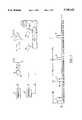
- FIG. 1shows a conventional pulse doppler radar system in which the location and speed of an object 24, such as an aircraft, can be determined.
- a transmitter 10produces a signal S0 which includes a batch of pulses 12, 14, 16 and 18.
- Each pulse 12-18has a width W0, a magnitude M0, a phase ⁇ 0 , and is separated by a pulse repetition interval (PRI).
- PRIpulse repetition interval
- Each PRIcontains a number of range cells which have been designated as R1-R10.
- the signal S0 produced by the transmitter 10enters a duplexer 20 which routes the signal S0 to an antenna 22.
- the antenna 22radiates the signal S0 into space toward the object 24.
- the receiver 26converts the signal S1 to a lower frequency, samples the signal at each range cell R1-R10 in each PRI, and digitizes each sample to develop a signal S2.
- the signal S2which is shown in FIG. 2, includes echos 30, 32, 34 and 36. These echos indicate the presence of the object 24.
- the arrival time and phase ⁇ 2 of each echo 30-36is compared to the transmission time and phase ⁇ 0 of each pulse 12-18 of signal S0 to calculate the range and speed of the object 24.
- the signal S2 produced by the receiver 26includes other information as well.
- the signal S2includes unwanted echos known as clutter and ElectroMagentic Interference (EMI).
- Clutteris present in the signal S2 as a result of the signal S1 being reflected from objects such as the sea, land, rain or chaff.
- EMIis present in the signal S2 as a result of pulses transmitted from other radar systems.
- the clutter and EMI contained within the signal S2produce undesirable results.
- peaks in the signal S2, which represents clutter or EMIare many times mistakenly identified as an object of interest. This results in an undesirably high number of false alarms.
- FIG. 3shows a conventional radar system which includes a clutter filter 40, an EMI detection unit 42, and a logical AND gate 44.
- the clutter filter 40includes a Doppler Filter Bank (DFB) 46, a plurality of cell averaging (CA) constant false alarm rate (CFAR) devices 48, a plurality of threshold devices 50, and a logical OR gate 52. As is described below, these devices work in combination to filter the clutter component from the signal S2.
- DFBDoppler Filter Bank
- CAcell averaging
- CFARconstant false alarm rate
- the DFB 46 contained within the clutter filter 40which is shown in FIG. 4, includes a first memory device 54, a Fourier Transform Device (FTD) 56, and a second memory device 58.
- the first memory device 54is an array which stores the magnitude M2 and phase shift ⁇ 2 for range cells R1-R10 at each PRI of the signal S2 shown in FIG. 2.
- this datais stored in the first memory device 54, it is transformed from the time domain to the frequency domain by the FTD 56.
- the data in range cells R1 through Rni.e, column 1, column 2, etc
- the resultsare then stored in the second memory device 58.
- each row the of second memory device 58represents the magnitude M2 and phase ⁇ 2 of each range cell operating at a certain frequency. That is, row 1 of the second memory device 58 represents the magnitude and phase of the signal S2 at frequency F1 for each range cell. Similarly, row 2 represents the magnitude and phase of the signal S2 at frequency F2 for each range cell.
- each CA CFAR device 48includes a Moving Window Average Calculator (MWAC) 60 and a normalizer 62.
- the MWAC 60computes a Moving Window Average (MWA) for each range cell of the signal S3, where the MWA represents either an arithmetic average or a logarithmic average.
- the calculated MWAwhich is shown as SB, as is known in the art, represents the average background of the local range about each range cell in the signal S3.
- the value of the signal SBis used to normalize the value of each range cell stored in the second memory device 58. That is, the normalizer 62 divides the value stored in the second memory device 58 for each range cell by the value SB calculated for each range cell and then subtracts a factor of 1 from this value to produce a signal S4. The subtraction of the factor 1 by the normalizer 62 is, however, optional.
- the values for each range cell contained within the signal S4are then compared to a threshold value by a threshold device 50. If the value of each range cell contained in the signal S4 is greater than the threshold value, a factor of 1 is selected. On the other hand, if the value of the signal S4 is less than the threshold value, a factor of 0 is selected.
- FIG. 6shows a hypothetical set of values for the signal S5 which have been produced by the the threshold devices 50 and sent to the the logical OR gate 52.
- the logical OR gate 52performs a binary OR operation on these values. Specifically, the binary values within each range cell (i.e., each column) of data are compared to each other by the logical OR gate 52. If any value is within the range cell is found to equal 1, the value for the entire range cell will be designated as a 1. Conversely, if any value is within the range cell is found to equal 0, the value for the entire range cell will be designated as a 0.
- signal S6The results of this logical operation performed by the logical OR gate 52 are presented in signal S6.
- the signal S6is essentially free of clutter and contains data which represents either a target or EMI. That is, each range cell in signal S6 which contains a 1 is considered to represent either a target or EMI.
- the conventional radar system shown in FIG. 3now must detect which range cells within the signal S6 represent EMI.
- the EMI detection unit 42performs this detection task. Specifically, as is described below, the EMI detection unit 42 detects range cells representing EMI by use of a high pass filter 64, a memory device 66, and EMI detector 68.
- the high pass filter 64is typically an n-pulsed canceler. Most of the clutter in the signal S2 is contained in the low frequency components of the signal. As a result, the high pass filter 64, which removes the low frequency components from the signal S2, removes most of the clutter. Thus, as a result of this filtering, the signal S7 produced by the high pass filter 64 represents either EMI or an object of interest.
- the signal S7is then sent to memory device 66.
- the data stored in the memory device 66represents the magnitude M7 of each range cell in the signal S7.
- each range celli.e., each column
- the EMI detector 68passes the data in each range cell through an algorithm to determine if the data in the range cell represents EMI or a target.
- the algorithm used by the EMI detector 68looks for one unusually large pulse in each range cell of the signal S7. If such a pulse is identified, the data in the range cell is considered to represent EMI. Conversely, if such a pulse is not identified, the data in the range cell is considered to represent an object of interest.
- the EMI detector 68produces a signal S8 which is shown in FIG. 8.
- Each range cell in the signal S8 produced by the EMI detector 68is assigned a value of 1 unless EMI had been detect in the range cell. If this is the case, the range cell is assigned a value of 0.
- the signal S8is then sent to the logical AND gate 44 along with signal S6.
- the logical AND gate 44performs a binary AND operation on these two signals. That is, range cell R1 of signal S6 is compared with range cell R1 of signal S8 and when both values are found to equal 1 the value for the range cell R1 of signal S9 will be designated as 1.
- each range cell of the signal S9will have been passed through both the clutter filter 40 and EMI detection unit 42.
- each range cell in the signal S9 containing a 1is considered to represent a true object of interest.
- the signal S9is then presented on the video screen 28 for review by a video operator.
- the conventional radar system shown in FIG. 3does, however, have certain drawbacks.
- the EMI detector 68is only effective if the clutter echos contained in the signal S2 are sufficiently filtered prior to producing the signal S7.
- the high pass filter 64 used in conventional devicesfails in this regard. Specifically, the high pass filter 64 used in conventional devices removes only the low frequency clutter components from the signal S2 prior to producing the signal S7.
- the signal S7contains significant residues from high frequency clutter echos.
- the EMI detector 68can not effectively detect the EMI since the EMI is masked by the clutter residue. As a result, many EMI pulses remain undetected and an undesirably high number of false alarms are included in the signal S9.
- a radar systemfor identifying an object of interest.
- the radar systemcomprises (i) a transmitter means for producing a first signal, where the first signal includes a plurality of pulses separated by a pulse repetition interval (PRI) where each PRI contains a plurality of range cells; (ii) a duplexer means for receiving and processing the signals, where the duplexer means receives the first signal from the transmitter; (iii) an antenna which receives the first signal from the duplexer means and transmits the first signal into the atmosphere, receives a second signal reflected by objects present in the atmosphere, and routes the second signal to the duplexer; (iv) a receiving means which receives the second signal from the duplexer, samples the second signal at all range cells, and develops a third signal; (v) a clutter filtering means which filters a clutter component from the third signal at all frequencies and develops a fourth signal which is free from clutter; (vi) an electromagnetic interference (EMI) detection means which identifies EMI present in
- the EMI detection meansfurther includes (i) an inverse Doppler filter bank and (ii) an EMI detector.
- the EMI detectorincludes: (i) a means for examining a plurality of contiguous values contained within each range cell of the fourth signal (ii) a means for comparing the largest value found in each range cell to each remaining nonadjacent value in each range cell and calculating a factor, (iii) a means for assigning each range cell a value, where the assigned value is 1 when the factor is less than 2 and the assigned value is 0 when the factor is greater than 2.
- FIG. 1illustrates a conventional radar system
- FIG. 2illustrates a signal S2 produced by the conventional radar system shown in FIG. 1;
- FIG. 3illustrates another conventional radar system
- FIG. 4illustrates a Doppler Filter Bank 46 shown in FIG. 3;
- FIG. 5illustrates a CA CFAR Device 48 shown in FIG. 3;
- FIG. 6illustrates Logical OR Gate 52 shown in FIG. 3;
- FIG. 7illustrates Memory Device 66 shown in FIG. 3
- FIG. 8illustrates Logical AND Gate 44 shown in FIG. 3
- FIG. 9illustrates a radar system in accordance with the present invention.
- FIG. 10illustrates an Inverse Doppler Filter Bank 84 shown in FIG. 9.
- FIG. 9shows a radar system in accordance with the present invention.
- a radar system designed in accordance with the present inventionincludes an EMI detection unit 82 which contains an Inverse Doppler Filter Bank (DBF) 84 and an EMI detector 88.
- the Inverse DFB 84includes a first memory device 85, an Inverse Fourier Transform Device (FTD) 86, and second memory device 87.
- the first memory device 85is an array which stores the magnitude and phase of the signal S4 at frequencies F1 through Fn for each range cell. Once the data is stored in the first memory device 85 it is transformed from the frequency domain back to the time domain, as is known in the art, by the inverse FTD 86. The results, which are shown as signal S7 are then stored in the second memory device 87.
- the values of the signal S7 within each range cellare then analyzed by the EMI detector 68 in accordance with a newly developed algorithm to detect the echos resulting from EMI.
- the algorithm used by the EMI detector 68compares the amplitude of the largest value found in each range cell with that of the largest remaining nonadjacent pulses of the range cell. If, when these two values are compared, a ratio greater than 2 is found to exist, the data in the range cell is considered to represent EMI. Conversely, if a ratio less than 2 is found to exist the data in the range cell is considered to represent a target.
- the results of the EMI detector 68produces a signal S8.
- Each range cell in the signal S8 produced by the EMI detector 68is assigned a value of 1 unless EMI had been detect in the range cell. If this is the case, the range cell is assigned a value of 0.
- the signal S8is then compare with the signal S6 in a manner consistent with conventional devices.
- a radar system used in accordance with the present inventionproduces a signal S7 which has been adaptively filtered to remove both low frequency and high frequency clutter components, without masking the EMI pulses which require detection.
- the DFB 46, the CA CFAR devices 48 and the Inverse DFB 84work in combination to adaptively filter clutter components received by the radar system, irrespective of frequency, while simultaneously passing EMI pulses for detection.
- the signal S7 produced by the inventionthe relative magnitude of the EMI pulses to the clutter echos is maximized and the EMI pulses can be optimally detected by the EMI detector 88. When this occurs, the number of false alarms contained in the signal S9 due to EMI decreases dramatically.
Landscapes
- Engineering & Computer Science (AREA)
- Radar, Positioning & Navigation (AREA)
- Remote Sensing (AREA)
- Computer Networks & Wireless Communication (AREA)
- Physics & Mathematics (AREA)
- General Physics & Mathematics (AREA)
- Spectroscopy & Molecular Physics (AREA)
- Radar Systems Or Details Thereof (AREA)
Abstract
Description
Claims (6)
Priority Applications (1)
| Application Number | Priority Date | Filing Date | Title |
|---|---|---|---|
| US08/772,160US5748142A (en) | 1996-12-20 | 1996-12-20 | Pulse doppler radar system which identifies and removes electromagnetic interference |
Applications Claiming Priority (1)
| Application Number | Priority Date | Filing Date | Title |
|---|---|---|---|
| US08/772,160US5748142A (en) | 1996-12-20 | 1996-12-20 | Pulse doppler radar system which identifies and removes electromagnetic interference |
Publications (1)
| Publication Number | Publication Date |
|---|---|
| US5748142Atrue US5748142A (en) | 1998-05-05 |
Family
ID=25094126
Family Applications (1)
| Application Number | Title | Priority Date | Filing Date |
|---|---|---|---|
| US08/772,160Expired - LifetimeUS5748142A (en) | 1996-12-20 | 1996-12-20 | Pulse doppler radar system which identifies and removes electromagnetic interference |
Country Status (1)
| Country | Link |
|---|---|
| US (1) | US5748142A (en) |
Cited By (12)
| Publication number | Priority date | Publication date | Assignee | Title |
|---|---|---|---|---|
| US20050059363A1 (en)* | 2003-09-15 | 2005-03-17 | Hansen Christopher J. | Radar detection from pulse record with interference |
| RU2308737C1 (en)* | 2006-02-22 | 2007-10-20 | Открытое акционерное общество "Концерн "Гранит-Электрон" | Radar station |
| US20070281638A1 (en)* | 2003-09-15 | 2007-12-06 | Broadcom Corporation | Radar detection circuit for a wlan transceiver |
| RU2410715C2 (en)* | 2009-04-03 | 2011-01-27 | Владимир Иванович Винокуров | Method of detecting signals belonging to one target and device for realising said method |
| US20120013503A1 (en)* | 2009-01-29 | 2012-01-19 | Stefan Heilmann | Method for detecting precipitaton using a radar locating device for motor vehicles |
| RU2522910C2 (en)* | 2012-11-06 | 2014-07-20 | Российская Федерация, От Имени Которой Выступает Министерство Промышленности И Торговли Российской Федерации | Automatic navigation radar with longer non-supervised self-contained operating period |
| US9030351B2 (en)* | 2006-06-08 | 2015-05-12 | Vista Research, Inc. | Sensor suite and signal processing for border surveillance |
| US20150338513A1 (en)* | 2014-05-20 | 2015-11-26 | Hyundai Mobis Co., Ltd. | Apparatus and method for detecting target using radar |
| US10120070B2 (en)* | 2013-03-12 | 2018-11-06 | Furuno Electric Company Limited | Detection device, radar device, detection method, and detection program |
| RU2691129C1 (en)* | 2018-07-20 | 2019-06-11 | Открытое акционерное общество "Научно-производственный комплекс "Научно-исследовательский институт дальней радиосвязи" (ОАО "НПК "НИИДАР") | All-round radar |
| RU2697504C2 (en)* | 2016-11-21 | 2019-08-15 | Общество с ограниченной ответственностью "Научно-производственное предприятие "Цифровые радиотехнические системы" | Aerodrome radar set of air traffic control |
| RU2713380C1 (en)* | 2019-06-18 | 2020-02-05 | федеральное государственное автономное образовательное учреждение высшего образования "Южный федеральный университет" | Digital signal processing method in pulse-doppler radar with high repetition rate and device for its implementation |
Citations (3)
| Publication number | Priority date | Publication date | Assignee | Title |
|---|---|---|---|---|
| US4635060A (en)* | 1984-06-05 | 1987-01-06 | Rca Corporation | Coherent-on-receive radar with prephase correction circuit |
| US5184137A (en)* | 1980-12-29 | 1993-02-02 | Raytheon Company | All weather tactical strike system (AWTSS) and method of operation |
| US5646623A (en)* | 1978-05-15 | 1997-07-08 | Walters; Glenn A. | Coherent, frequency multiplexed radar |
- 1996
- 1996-12-20USUS08/772,160patent/US5748142A/ennot_activeExpired - Lifetime
Patent Citations (3)
| Publication number | Priority date | Publication date | Assignee | Title |
|---|---|---|---|---|
| US5646623A (en)* | 1978-05-15 | 1997-07-08 | Walters; Glenn A. | Coherent, frequency multiplexed radar |
| US5184137A (en)* | 1980-12-29 | 1993-02-02 | Raytheon Company | All weather tactical strike system (AWTSS) and method of operation |
| US4635060A (en)* | 1984-06-05 | 1987-01-06 | Rca Corporation | Coherent-on-receive radar with prephase correction circuit |
Cited By (21)
| Publication number | Priority date | Publication date | Assignee | Title |
|---|---|---|---|---|
| US20070281638A1 (en)* | 2003-09-15 | 2007-12-06 | Broadcom Corporation | Radar detection circuit for a wlan transceiver |
| US7702291B2 (en)* | 2003-09-15 | 2010-04-20 | Broadcom Corporation | Radar detection from pulse record with interference |
| US7701382B2 (en) | 2003-09-15 | 2010-04-20 | Broadcom Corporation | Radar detection circuit for a WLAN transceiver |
| US20100194623A1 (en)* | 2003-09-15 | 2010-08-05 | Broadcom Corporation | Radar detection circuit for a WLAN transceiver |
| US8081104B2 (en)* | 2003-09-15 | 2011-12-20 | Broadcom Corporation | Radar detection circuit for a WLAN transceiver |
| US20050059363A1 (en)* | 2003-09-15 | 2005-03-17 | Hansen Christopher J. | Radar detection from pulse record with interference |
| RU2308737C1 (en)* | 2006-02-22 | 2007-10-20 | Открытое акционерное общество "Концерн "Гранит-Электрон" | Radar station |
| US9696409B2 (en)* | 2006-06-08 | 2017-07-04 | Vista Research, Inc. | Sensor suite and signal processing for border surveillance |
| US9030351B2 (en)* | 2006-06-08 | 2015-05-12 | Vista Research, Inc. | Sensor suite and signal processing for border surveillance |
| US20120013503A1 (en)* | 2009-01-29 | 2012-01-19 | Stefan Heilmann | Method for detecting precipitaton using a radar locating device for motor vehicles |
| US8581774B2 (en)* | 2009-01-29 | 2013-11-12 | Robert Bosch Gmbh | Method for detecting precipitation using a radar locating device for motor vehicles |
| RU2410715C2 (en)* | 2009-04-03 | 2011-01-27 | Владимир Иванович Винокуров | Method of detecting signals belonging to one target and device for realising said method |
| RU2522910C2 (en)* | 2012-11-06 | 2014-07-20 | Российская Федерация, От Имени Которой Выступает Министерство Промышленности И Торговли Российской Федерации | Automatic navigation radar with longer non-supervised self-contained operating period |
| US10120070B2 (en)* | 2013-03-12 | 2018-11-06 | Furuno Electric Company Limited | Detection device, radar device, detection method, and detection program |
| DE102014108863A1 (en)* | 2014-05-20 | 2016-01-28 | Hyundai Mobis Co., Ltd. | Apparatus and method for detecting targets using radar |
| US20150338513A1 (en)* | 2014-05-20 | 2015-11-26 | Hyundai Mobis Co., Ltd. | Apparatus and method for detecting target using radar |
| US9726758B2 (en)* | 2014-05-20 | 2017-08-08 | Hyundai Mobis Co., Ltd. | Apparatus and method for detecting target using radar |
| DE102014108863B4 (en)* | 2014-05-20 | 2021-02-11 | Hyundai Mobis Co., Ltd. | Apparatus and method for detecting targets using radar |
| RU2697504C2 (en)* | 2016-11-21 | 2019-08-15 | Общество с ограниченной ответственностью "Научно-производственное предприятие "Цифровые радиотехнические системы" | Aerodrome radar set of air traffic control |
| RU2691129C1 (en)* | 2018-07-20 | 2019-06-11 | Открытое акционерное общество "Научно-производственный комплекс "Научно-исследовательский институт дальней радиосвязи" (ОАО "НПК "НИИДАР") | All-round radar |
| RU2713380C1 (en)* | 2019-06-18 | 2020-02-05 | федеральное государственное автономное образовательное учреждение высшего образования "Южный федеральный университет" | Digital signal processing method in pulse-doppler radar with high repetition rate and device for its implementation |
Similar Documents
| Publication | Publication Date | Title |
|---|---|---|
| US11592520B2 (en) | FMCW radar with interfering signal suppression in the time domain | |
| US3701149A (en) | Frequency averaging controlled false alarm rate (cfar) circuit | |
| EP1672379B1 (en) | System and method for reducing a radar interference signal | |
| US5539412A (en) | Radar system with adaptive clutter suppression | |
| US5748142A (en) | Pulse doppler radar system which identifies and removes electromagnetic interference | |
| US5644315A (en) | Doppler ratio detection radar with range CFAR | |
| US4079376A (en) | Target detection system in a medium PRF pulse doppler search/track radar receiver | |
| US4095222A (en) | Post-detection stc in a medium prf pulse doppler radar | |
| US8125374B2 (en) | Method of preventing false detections in sensors | |
| US4249177A (en) | Target discrimination apparatus | |
| WO2018098234A1 (en) | System and technique for mitigation of clutter in radar | |
| US6765525B2 (en) | Method for reducing false alarm rate in radar images | |
| EP0126032B1 (en) | Device for the identification and suppression of unwanted second trace echoes in radar systems | |
| US5808579A (en) | Radar system using a cell averaging constant false alarm rate device | |
| Turley | Hybrid CFAR techniques for HF radar | |
| US4104633A (en) | Extended target-log CFAR processor | |
| US4714927A (en) | Pulse doppler radar with variable pulse repetition rate | |
| EP0100012A2 (en) | Device for post-detection cancelling of erroneous radar echos | |
| NL9401767A (en) | Radar device. | |
| JPH0158467B2 (en) | ||
| US3631489A (en) | Mti system having improved discrimination of targets displaying ambiguous doppler shifts | |
| US5231402A (en) | Method for detecting and classifying helicopters | |
| US4489320A (en) | Interference suppressor for radar MTI | |
| US4524360A (en) | Pulse radar apparatus | |
| US4513287A (en) | Device for the elimination of nth trace moving echoes and interference echoes in a radar |
Legal Events
| Date | Code | Title | Description |
|---|---|---|---|
| AS | Assignment | Owner name:NORTHROP GRUMMAN CORPORATION, MARYLAND Free format text:ASSIGNMENT OF ASSIGNORS INTEREST;ASSIGNOR:RADEMACHER, PAUL E.;REEL/FRAME:008374/0700 Effective date:19961113 | |
| FEPP | Fee payment procedure | Free format text:PAYOR NUMBER ASSIGNED (ORIGINAL EVENT CODE: ASPN); ENTITY STATUS OF PATENT OWNER: LARGE ENTITY | |
| FPAY | Fee payment | Year of fee payment:4 | |
| REMI | Maintenance fee reminder mailed | ||
| FPAY | Fee payment | Year of fee payment:8 | |
| FEPP | Fee payment procedure | Free format text:PAYOR NUMBER ASSIGNED (ORIGINAL EVENT CODE: ASPN); ENTITY STATUS OF PATENT OWNER: LARGE ENTITY Free format text:PAYER NUMBER DE-ASSIGNED (ORIGINAL EVENT CODE: RMPN); ENTITY STATUS OF PATENT OWNER: LARGE ENTITY | |
| FPAY | Fee payment | Year of fee payment:12 | |
| AS | Assignment | Owner name:NORTHROP GRUMMAN SYSTEMS CORPORATION, CALIFORNIA Free format text:ASSIGNMENT OF ASSIGNORS INTEREST;ASSIGNOR:NORTHROP GRUMMAN CORPORATION;REEL/FRAME:025597/0505 Effective date:20110104 |