US5748116A - System and method for nested split coding of sparse data sets - Google Patents
System and method for nested split coding of sparse data setsDownload PDFInfo
- Publication number
- US5748116A US5748116AUS08/758,590US75859096AUS5748116AUS 5748116 AUS5748116 AUS 5748116AUS 75859096 AUS75859096 AUS 75859096AUS 5748116 AUS5748116 AUS 5748116A
- Authority
- US
- United States
- Prior art keywords
- data
- data block
- block
- bit length
- value
- Prior art date
- Legal status (The legal status is an assumption and is not a legal conclusion. Google has not performed a legal analysis and makes no representation as to the accuracy of the status listed.)
- Expired - Lifetime
Links
Images


Classifications
- H—ELECTRICITY
- H04—ELECTRIC COMMUNICATION TECHNIQUE
- H04N—PICTORIAL COMMUNICATION, e.g. TELEVISION
- H04N19/00—Methods or arrangements for coding, decoding, compressing or decompressing digital video signals
- H04N19/60—Methods or arrangements for coding, decoding, compressing or decompressing digital video signals using transform coding
- H04N19/61—Methods or arrangements for coding, decoding, compressing or decompressing digital video signals using transform coding in combination with predictive coding
- G—PHYSICS
- G06—COMPUTING OR CALCULATING; COUNTING
- G06V—IMAGE OR VIDEO RECOGNITION OR UNDERSTANDING
- G06V10/00—Arrangements for image or video recognition or understanding
- G06V10/20—Image preprocessing
- H—ELECTRICITY
- H04—ELECTRIC COMMUNICATION TECHNIQUE
- H04N—PICTORIAL COMMUNICATION, e.g. TELEVISION
- H04N19/00—Methods or arrangements for coding, decoding, compressing or decompressing digital video signals
- H04N19/60—Methods or arrangements for coding, decoding, compressing or decompressing digital video signals using transform coding
- H04N19/61—Methods or arrangements for coding, decoding, compressing or decompressing digital video signals using transform coding in combination with predictive coding
- H04N19/619—Methods or arrangements for coding, decoding, compressing or decompressing digital video signals using transform coding in combination with predictive coding the transform being operated outside the prediction loop
- H—ELECTRICITY
- H04—ELECTRIC COMMUNICATION TECHNIQUE
- H04N—PICTORIAL COMMUNICATION, e.g. TELEVISION
- H04N19/00—Methods or arrangements for coding, decoding, compressing or decompressing digital video signals
- H04N19/60—Methods or arrangements for coding, decoding, compressing or decompressing digital video signals using transform coding
- H04N19/63—Methods or arrangements for coding, decoding, compressing or decompressing digital video signals using transform coding using sub-band based transform, e.g. wavelets
- H—ELECTRICITY
- H04—ELECTRIC COMMUNICATION TECHNIQUE
- H04N—PICTORIAL COMMUNICATION, e.g. TELEVISION
- H04N19/00—Methods or arrangements for coding, decoding, compressing or decompressing digital video signals
- H04N19/10—Methods or arrangements for coding, decoding, compressing or decompressing digital video signals using adaptive coding
- H04N19/102—Methods or arrangements for coding, decoding, compressing or decompressing digital video signals using adaptive coding characterised by the element, parameter or selection affected or controlled by the adaptive coding
- H04N19/13—Adaptive entropy coding, e.g. adaptive variable length coding [AVLC] or context adaptive binary arithmetic coding [CABAC]
Definitions
- the present inventionrelates generally to systems and methods for lossless compression and reconstruction of data, such as the quantized wavelet coefficients of a wavelet transformed image, that is sparsely populated by non-zero data, and particularly to a system and method for efficiently identifying and encoding portions of a data set occupied by zero and near-zero values.
- Sparsely populated data setsare utilized in numerous technical fields.
- the present inventionwas developed for efficiently encoding image data that has been transformed by successive applications of wavelet transforms, but is equally applicable to other types of sparsely populated data sets.
- Image data that has been transformed by successive applications of wavelet transformstends to have large portions occupied by zero and near-zero values, especially if the data is subjected to a data quantization step prior to encoding.
- the primary goals of the present inventionare to provide an encoding methodology that (A) efficiently locates subarrays that are entirely occupied by zero data and encoding such subarrays with as few data bits as possible, (B) determines the maximum number of data bits required to encode subarrays that include at least some non-zero data, and (C) encodes non-zero data with the minimum number of data bits required to losslessly store such data.
- the present inventionis a system and method for encoding an array of data.
- the data encoding methodsuccessively analyzes successively smaller blocks of a specified data array.
- Data blocksare analyzed in a predefined order, and corresponding entries identifying data blocks containing at least one non-zero value are stored in that same order in a list of blocks.
- a data blockis processed, if the data block is entirely filled with zero data it is so identified in the output data and no further processing of the data block is required. Otherwise, if the size of the data block is greater than a predefined minimum block size (e.g., 2 ⁇ 2), the block is divided into smaller data blocks and those smaller data blocks are put on the list of blocks for further processing.
- a predefined minimum block sizee.g., 2 ⁇ 2
- values representing all the data items in that data blockare written into the output data.
- Information identifying the minimum number of bits required to encode the largest data value in each data blockis written into the output data in the same order that the blocks are analyzed, thereby enabling a decoder procedure to determine the number of data bits used to encode each data value stored in the output data.
- the data decoding methodretraces the encoded data so as to reverse the process performed by the encoding method.
- the bits of the encoded dataare read, in order, in a single pass from the first bit to the last. When the last data bit in the encoded data has been processed, reconstruction of the encoded data array is complete.
- entriesare added to a block list to identify data blocks that will be processed later, along with the data indicating the maximum number of bits needed to encode the data in those data blocks.
- Data blocksare analyzed in the order they appear in the encoded data. Whenever a data block is processed, if the data block is entirely filled with zero data, the relevant portion of the reconstructed data array is filled with zero data values. Otherwise, data block identifiers are added to the block list until data blocks of a predetermined minimum size (e.g., 2 ⁇ 2) are encountered, at which point the data values in each such data block are decoded and output to the reconstructed data array.
- a predetermined minimum sizee.g., 2 ⁇ 2
- FIG. 1is a block diagram of an image processing workstation incorporating a first preferred embodiment of the present invention.
- FIG. 2schematically represents an image data array and an overlapping set of data analysis arrays.
- FIGS. 3A and 3Bdepict node list and block list data structures used by the data encoder and data decoder of the preferred embodiments.
- FIGS. 4 and 5are flow charts of a preferred embodiment of the data encoding method of the present invention.
- FIG. 6is a sample array of data used for demonstrating the operation of the first preferred embodiment the present invention.
- FIGS. 7 and 8are flow charts of a preferred embodiment of the data decoding method of the present invention.
- FIG. 9is a block diagram of an image processing workstation incorporating a second preferred embodiment of the present invention.
- FIGS. 10, 11 and 12are flow charts of a second preferred embodiment of the data encoding method of the present invention.
- FIGS. 13, 14 and 15are flow charts of a second preferred embodiment of the data decoding method of the present invention.
- the system 300includes a central processing unit 302, internal system, control and data busses 304, memory 306 (including random access memory as well as non-volatile memory such as magnetic disk storage), a user interface 308, and a communications interface 310 for transferring information to and from other devices via one or more communication channels 312.
- a central processing unit 302internal system, control and data busses 304, memory 306 (including random access memory as well as non-volatile memory such as magnetic disk storage), a user interface 308, and a communications interface 310 for transferring information to and from other devices via one or more communication channels 312.
- Memory 306stores both computer software and data, including:
- raw image data 322such as image data files generated by a digital camera, CAT scan device, MR imaging system, or an image scanner;
- encoded data 324such as compressed image data files generated by a data encoder or data encoding procedure
- reconstructed image data 326such as reconstructed image data files generated by a data decoder and wavelet data reconstruction procedure
- an image processing module 330for processing image data.
- the image processing module 330includes:
- processed image data files or storage arrays 340for temporarily storing wavelet analyzed data or decoded data
- node list and block list data structures 353, 354for storing data utilized by the encoder and decoder procedures 336, 338.
- the present inventionis suitable for use with any sparsely populated data set.
- the specific type of wavelet transform procedure 332 used and the specific type of data quantization procedure 334 used to transform an image file into a processed image data fileare not relevant and therefore are not further described herein.
- a preferred embodiment of the wavelet transform procedure 332 and the data quantization procedure 334are described in U.S. patent application No. 08/xxx,xxx, filed xx, 1996, "System and Method for Performing Wavelet and Inverse Wavelet Like Transformations of Digital Data Using Only Add and Bit Shift Arithmetic Operations," which is hereby incorporated by reference as background information.
- Each analysis array 350is a square N ⁇ N array, such as a 32 ⁇ 32 array.
- a sufficient number of analysis arraysare used to cover the entire data array 322 that is to be encoded, even if some of the analysis arrays overhang the edges of the data array. The overhanging portions of the analysis arrays are filled with zero data values during the data encoding process.
- An analysis array size of 32 ⁇ 32is convenient because an 11 ⁇ 9 set of such analysis arrays perfectly covers a 352 ⁇ 288 data array, which is a fairly commonly used image data array size.
- the origin of the data arrayis the top left corner
- the first coordinate used to identify data array positionsis the "Y" axis or vertical coordinate
- the second coordinate usedis the "X" axis or horizontal coordinate.
- a position of 0,64indicates a pixel at the top vertical position of the array, 64 pix positions over to the right from the array origin, while a position of 32,0 indicates a pixel on the left edge of the array, 32 pixel positions vertically down from the array origin.
- a node list data structure 353lists nodes (in the data array) being analyzed
- a block list data structure 354lists data blocks (i.e., subarrays of data) being analyzed.
- the node list 353, which is used only in the second preferred embodimentstores a node identifier (i.e., x and y coordinates) for each node in the list.
- the block list 354stores two items for each data block: (A) a block identifier consisting of two values indicating the origin of the data block and a value indicating the height and width of the data block, and (B) a value indicating the maximum number of bits required to represent any data value in the data block (i.e., int(log 2 V)+1, where "into" represents the integer portion of a specified value).
- each list 353, 354has a respective a first pointer 351, 356 that points to the node or block highest in the list 351, 354 that has not yet been processed, and a second pointer 352, 358 that points to the highest unused slot in the list 353, 354.
- data preparationconsists of performing a wavelet transformation (using wavelet procedure 332) of an image data array, followed by quantization (using data quantization procedure 334) of the resulting data to a predefined set of discrete data values.
- the wavelet transformation and quantization data preparation stepstypically generate a data array sparsely populated with non-zero data.
- the encoder procedureis suitable for encoding virtually any data array, including three-dimensional and N-dimensional data arrays.
- the encoder procedure 336works, in general, by analyzing successively smaller blocks of a specified data array.
- Data blocksare analyzed in the order they appear in the list of blocks 354.
- the data blockis determined to be entirely filled with zero data (i.e., data values all equal to zero, also called null data) it is so identified in the output data and no further processing of the data block is required. Otherwise, if the size of the data block is greater than 2 ⁇ 2, the data block is divided into four smaller subblocks and those four smaller subblocks are put on the list of blocks for further processing.
- the encoder procedurebegins by determining the height and width of the specified data array to be encoded and outputting those values to the output file (step 360), and then determining the number of analysis arrays needed to cover the specified data array. For example, when using a 32 ⁇ 32 analysis array, the number of analysis arrays needed may be determined by truncating the five least significant bits from the values of "31+data array height" and "31+data array width". In some applications the height and width may be permanently fixed, in which case steps 360 and 362 may be omitted. Then, an analysis array encoder procedure is called successive times to encode each of the analysis arrays required to cover the specified data array (step 364).
- Table 1provides definitions of terms and abbreviations used in the flow chart figures.
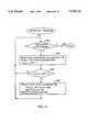
- the procedure for encoding an array of 2 n ⁇ 2 n data valuesbegins by putting a first entry, representing the entire 2 n ⁇ 2 n analysis array, in the list of blocks (step 370).
- the list of blocksis empty except for this first entry.
- the encoding proceduredetermines the value of Bit(0,0,n), which is equal to the maximum number of bits required to encode any data value in the entire array being analyzed, and outputs that value using a predefined number of bits (e.g., 4 bits). If Bit(0,0,n) is equal to zero (step 371), that indicates that all the nodes in the array to be encoded are equal to zero, and therefore the encoding procedure is complete (step 396).
- the procedureselects the next unprocessed data block (h,w,k) from the block list and sets a variable B equal to the maximum number of bits required to encode any data value in the selected data block (step 374).
- step 376If the size of the selected data block is not equal to or smaller than a predefined minimum block size, such as 2 ⁇ 2 (step 376), the following steps are performed for each of the four subblocks of the selected block.
- the entry in the block listincludes the value b to indicate the maximum number of bits required to encode the data in the subblock.
- the maximum number of bits required to encode data in the subblockis determined and that value is both stored in the block list (or in a parallel data array) and output as a corresponding sequence of 0's terminated with a 1 bit.
- This processis then repeated for the other three subblocks of the selected block (steps 380, 382, 384).
- the pointer 356 to the next processed blockwill be advanced by one position at step 374 if there are any unprocessed data blocks left in the block list (step 372).
- step 376all the data values in the block are encoded and output as follows.
- Each data valueis output using B bits, where B is the number of bits denoted in the block list for this block, and is equal to the maximum number of bits used by any data value in the selected block.
- a sign bitis also output (steps 388, 390, 392, 394).
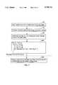
- FIG. 6shows an example of sparsely populated 16 ⁇ 16 data array.
- Table 2shows the data output while encoding this data array using the procedure shown in FIG. 5.
- the decoder procedure 336works, in general, by reading and interpreting the encoded data so as to reverse the process performed by the encoder procedure 336.
- the bits of the encoded dataare read, in order, in a single pass from the first bit to the last. When the last data bit in the encoded data has been processed, reconstruction of the encoded data array is complete.
- entriesare added to the block list to identify the data blocks and subblocks that will be processed later in the procedure, along with the data indicating the maximum number of bits needed to encode the data in those blocks and subblocks.
- Data blocks and subblocksare analyzed in the order they appear in the encoded data. Whenever a subblock is processed, if the subblock is entirely filled with zero data (i.e., data values all equal to zero), the relevant portion of the reconstructed data array is filled with zero data values. Otherwise, subblock identifiers are added to the block list until subblocks whose size is 2 ⁇ 2 are encountered, at which point the four values in the subblock are decoded and output to the reconstructed data array.
- the decoder procedurebegins by reading (inputting) from the encoded data the height and width of the data array to be decoded and reconstructed (step 400), initializing the reconstructed image array to all zero values (step 401), and then determining the number of analysis arrays needed to cover the specified data array (step 402). Then, an analysis array decoder procedure (shown in FIG. 8) is called successive times to decode each of the analysis arrays required to cover the specified data array (step 404). After the decoding process is complete, the resulting reconstructed data may be subjected to a post-processing procedure (step 406), such as a reverse wavelet transformation procedure so as to reconstruct an image file.
- a post-processing proceduresuch as a reverse wavelet transformation procedure
- the procedure for decoding a set of encoded data representing an array of 2 n ⁇ 2 n data valuesbegins by putting a first entry, representing the entire 2 n ⁇ 2 n analysis array, in the list of blocks (step 410).
- the list of blocksis empty except for this first entry.
- the decodingproceedsue inputs a "bit length value", Bit(0,0,n), having a predefined number of bits (e.g., 4 bits) that represents the maximum number of bits used to encode any data value in the entire array being decoded.
- This bit length valueis stored in the block list in the entry representing the entire analysis array. If the bit length value, Bit(0,0,n), is equal to zero (step 411), that indicates that all the nodes in the array to be decoded are equal to zero, and therefore the decoding procedure is complete (step 440).
- the procedureselects the next unprocessed block (h,w,k) from the block list and reads from the block list a value B equal to the maximum number of bits required to encode any data value in the block (step 414).
- step 416If the size of the selected block is not a predefined minimum block size, such as 2 ⁇ 2 (step 416), the following steps are performed for each of the four subblocks of the selected block. Steps 418 and 420 are used to select each successive subblock and to exit the loop when all four subblocks have been processed. For each subblock, the encoded data bits are read until either a 1 bit is encountered or B bits are read without reading a 1 bit. The variable "repeat-times" keeps track of how many 0 bits have been read.
- a predefined minimum block sizesuch as 2 ⁇ 2
- Step 422If a 1 bit is read before repeat-times reaches a value of B, the subblock is added to the block list and a value of "B--repeat-times" is stored in the block list for the subblock, representing the maximum number of data bits used to encode the data in the subblock. If B zero bits are read, then the subblock contains only zero data and no entries are added to the block list (step 422). Note that no data values are written to the reconstructed data array in step 422 because there is no need to write zero data values to the reconstructed data array (see step 401 in FIG. 7). Steps 418, 420 and 422 are repeated until all four subblocks of the selected data block have been processed.
- the pointer 356 to the next processed block(see FIG. 3) will be advanced by one position at step 414 if there are any unprocessed data blocks left in the block lisk (step 412).
- the size of the selected data blockis the predefined minimum block size, such as 2 ⁇ 2 (step 416)
- all the values in the blockare decoded and output to the reconstructed data array (steps 430, 432, 434, 436, 437).
- the encoding procedure shown in FIG. 5is modified as follows.
- step 384when determining the maximum number of bits required to encode the last subblock of the currently selected block (h,w,k), if and only if the maximum number of bits required to encode each of the other three subblocks was less than B, the maximum number of bits required to encode data in the selected subblock, then it is known that at least one data value in the last subblock will require B bits to be encoded.
- the last subblockis added to the block list with a value of B denoted in the block list entry, but no data is added to the output.
- step 394if the values for the first three data values in the selected block were all smaller than 2 B-1 , then the topmost "1" bit of the last data value is not output since the presence of that "1" can be implied.
- steps 422 and 436are modified as follows.
- step 422when the first three subblocks of the selected block have been processed and none have a Bit(i,j,k-1) value of B, then there is no data to read for the fourth subblock. Restated, if the maximum number of bits required to encode each of the first three subblocks was less than B, then there is no data to read for the fourth subblock. When this condition is detected, no encoded data is read for the fourth subblock, but nevertheless an entry for the fourth subblock is added to the block list with a specified maximum number of bits required to encode data in the subblock being set to B, which is the maximum number of bits required to encode data in the selected (parent) block.
- step 436when the first data values in the selected block have been processed and all three have a value less than 2 B-1 , then the next data value to be read will have B-1 bits instead B bits, because its topmost bit is known to be equal to 1.
- B-1 bits of encoded dataare read for the fourth data value in the selected block, a 1 bit is pre-pended (i.e., concatenated) to that value as the most significant bit, and then normal processing of the fourth data value resumes.
- the data compression enhancement described above with respect to steps 384, 394, 422 and 436 of the encoder and decoder procedurestypically reduces the amount of encoded output data produced by 2 to 3 percent. Thus data compression is improved by 2 to 3 percent.
- the order of the encoding stepsis modified so as to slightly reduce the number of bits used to encode the nodes in a data array.
- the same terminology (see Table 1) and data structuresare used as in the first preferred embodiment, except that an additional list data structure called the node list data structure LN is used to keep track of a list of nodes.
- the beginning of the encoder procedure, as shown in FIG. 4remains unchanged.
- the procedure for encoding a an array of 2 n ⁇ 2 n data values shown in FIG. 5is replaced by the procedure shown in FIGS. 10, 11 and 12.
- the procedure for encoding an array of 2 n ⁇ 2 n data valuesbegins by putting a first entry, representing the entire 2 n ⁇ 2 n analysis array, in the list of blocks (step 500).
- the list of blocksis empty except for this first entry.
- the encoding proceduredetermines the maximum number of bits required to encode any data value in the entire array being analyzed and outputs that value using a predefined number of bits (e.g., 4 bits).
- a control variable mis then set to n, where n is equal to the number of bits required to encode the data sample with the largest absolute value in the entire specified set of data to be encoded (step 502). If the control variable m is initially equal to zero (step 510), that indicates that all the nodes in the array to be encoded are equal to zero, and therefore the encoding procedure is complete (step 512).
- the LN processing procedure (step 504), and LB processing procedure (step 506)are called. These two procedures process and encode nodes and blocks with respect to whether or not data samples in those nodes and blocks have an absolute value greater than 2 m-1 .
- the control variable mis decremented by 1 (step 508), and if m is still greater than zero (step 510), the two procedures are executed again (i.e., steps 504, 506 and 508 are repeated). This continues until m is decremented to a value of zero, at which point the encoding of the data array is complete (step 512).
- the LN encoding processing procedurebegins by determining if there are any unprocessed nodes in the list of nodes (step 520). Each time the LN processing procedure is called, the pointer 351 to the next unprocessed node is reset to the very first item in the list. The node list is initially empty when the encoding of each analysis array begins. At step 522 the next unprocessed node in the list of nodes is selected and one bit is output to indicate whether or not
- step 524If the absolute value
- the LN processing procedure of FIG. 11continues until all the nodes in the list of nodes have been processed.
- the nodes previously in the list whose absolute value was greater than or equal to 2 m-1have been encoded and removed from the list of nodes, while for each of the other nodes in the list a "0" bit has been output to indicate that each of those nodes have an absolute value less than 2 m-1 .
- the LB processing procedurebegins by determining if there are any unprocessed blocks in the list of blocks (step 540). Each time the LB processing procedure is called, the pointer 356 to the next unprocessed block is reset to the very first item in the list. Therefore, unless the list is empty, step 540 will detect the presence of unprocessed blocks in the list when the LB processing procedure is first called. However, at step 500 (FIG. 10) the list of blocks is initialized to include one entry. At step 542 the next unprocessed block in the list of blocks is selected and one bit is output to indicate whether or not V(i,j,k) ⁇ 2 m-1 . Thus, if there is at least one node in the (i,j,k) block whose absolute value is greater than or equal to 2 m-1 , a 1 bit is output and otherwise a 0 bit is output.
- step 544If the maximum absolute value of the nodes in the selected block
- a predetermined minimum block sizesuch as 2 ⁇ 2
- one bitis output to indicate whether or not
- the blockis divided into four smaller blocks
- step 550After either step 548 or 550, the selected block is removed from the list of blocks LB (set 552).
- the LB processing procedure of FIG. 12continues until all the blocks in the list of blocks have been processed.
- the blocks previously in the list that included at least one node whose absolute value was greater than or equal to 2 m-1have been removed from the list of blocks and divided into smaller blocks or divided into nodes that have been encoded or put on the node list, while for each of the other blocks in the list a "0" bit has been output to indicate that none of the nodes in those blocks have an absolute value greater than or equal to 2 m-1 .
- the procedure for decoding an array of 2 n ⁇ 2 n data valuesbegins by putting a first entry, representing the entire 2 n ⁇ 2 n analysis array, in the list of blocks (step 560).
- the list of blocksis empty except for this first entry.
- the encoding procedureinputs a value Bit(0,0,n) that indicates the maximum number of bits used to encode any data value in the entire array being decoded. If Bit(0,0,n) is equal to zero (step 570), that indicates that all the nodes in the array to be decoded are equal to zero, and therefore the decoding procedure is complete (step 572).
- a control variable mis set to Bit(0,0,n) (i.e., the maximum number of bits used to encode the data sample with the largest absolute value in the entire specified set of data to be decoded) (step 562).
- the LN decoding processing procedure (step 564), and LB decoding processing procedure (step 566)are called. These two procedures process and decode nodes and blocks with respect to whether or not data samples in those nodes and blocks have an absolute value greater than 2 m-1 .
- the control variable mis decremented by 1 (step 568), and if m is still greater than zero (step 570), the two procedures are executed again (i.e., steps 564, 566 and 568 are repeated). This continues until m is decremented to a value of zero, at which point the encoding of the data array is complete (step 572).
- the LN decoding processing procedurebegins by determining if there are any unprocessed nodes in the list of nodes (step 580). Each time the LN processing procedure is called, the pointer 351 to the next unprocessed node is reset to the very first item in the list. The node list is initially empty when the decoding of each analysis array begins. At step 582 the next unprocessed node in the list of nodes is selected and one bit is input that indicates whether or not
- step 584If the absolute value
- the LN processing procedure of FIG. 14continues until all the nodes in the list of nodes have been processed.
- the procedureis completed, the nodes previously in the list whose absolute value was greater than or equal to 2 m-1 have been decoded and removed from the list of nodes.
- the LB decoder processing procedurebegins by determining if there are any unprocessed blocks in the list of blocks (step 600). Each time the LB processing procedure is called, the pointer 356 to the next unprocessed block is reset to the very first item in the list. Therefore, unless the list is empty, step 600 will detect the presence of unprocessed blocks in the list when the LB decoder processing procedure is first called.
- the next unprocessed block in the list of blocksis selected and one bit is input that indicates whether or not
- step 604If the maximum absolute value of the nodes in the selected block
- a predetermined minimum block sizesuch as 2 ⁇ 2
- each node (x,y) in the (i,j,k) blockone bit is input indicating whether or not
- a corresponding node identifieris added to the end of the list of nodes LN (step 608). In addition, the value of each node that has been fully decoded is output to the reconstructed data array.
- the blockis divided into four smaller blocks
- step 610After either step 608 or 610, the selected block is removed from the list of blocks LB (set 612).
- the LB decoder processing procedure of FIG. 15continues until all the blocks in the list of blocks have been processed.
- the blocks previously in the list that included at least one node whose absolute value was greater than or equal to 2 m-1have been divided into smaller blocks or sets of nodes and removed from the list of blocks, while for each of the other blocks in the list a "0" bit has been output to indicate that none of the nodes in those blocks have an absolute value greater than or equal to 2 m-1 .
- the second preferred embodimentnormally generates the same amount of encoded data, but in a different order from the first preferred embodiment.
- decoders in accordance with the present inventionmight be included in a library of image viewer procedures distributed to users of various World Wide Web browsers, while only users interested in sending or distributing images to other persons might license the use of the encoder.
- a image or other data processing workstation 450contains the same components as described above with reference to the workstation 300 in FIG. 1, except that (A) the workstation includes an encoder/decoder circuit 452 for performing the encoding and decoding of N ⁇ N (e.g., 32 ⁇ 32) analysis arrays using hard coded logic circuitry, and (B) the encoder and decoder procedures are replaced by encoder and decoder control procedures 460, 462, which are shown in FIGS. 4 and 7, respectively.
- N ⁇ Ne.g., 32 ⁇ 32
- the sequence of encoding and decoding processing steps shown in FIGS. 5 and 8are performed by hard coded logic circuitry 452 that includes a state machine to control the sequential data processing.
- the state of the state machineis updated at each step in accordance with the data being processed and the data values stored in and read from the block list.
- the present inventionis equally applicable to the encoding and decoding of three-dimensional data arrays, and in fact is applicable to the encoding and decoding of N-dimensional data arrays where N is an integer greater than 0.
- Nis an integer greater than 0.
- the data analysis array sizemight be set to 32 ⁇ 32 ⁇ 32.
- Each data blockwould have eight subblocks that is one eighth the size of its parent data block, and the minimum size data block would likely be 2 ⁇ 2 ⁇ 2 in size, with eight data values requiring encoding. Given this block sizing and subblock scheme, the encoding and decoding methods would remain unchanged in all other respects.
- the number of data values contained in each identified data block(other than a block corresponding to the entire specified data array) will be equal to 2 -N times the number of data values in a corresponding parent data block, where N is an integer greater than zero.
- the encoding methodcould easily be modified so that the number of subblocks for each data block is two, or eight or sixteen, instead of the four used in the preferred embodiment, simply by redefining how each data block is to be divided into subblocks.
- the definition of the minimum size data blockcan be modified to be equal to any predefined number of data values, typically equal to an integer power of 2, and preferably equal to an integer power of 4.
- steps 370 and 378, 380, 382, 384for outputting values representing the bit length value for each identified data block
- steps 370 and 378, 380, 382, 384for outputting values representing the bit length value for each identified data block
- entropy codingsuch as Huffman or arithmetic coding
Landscapes
- Engineering & Computer Science (AREA)
- Multimedia (AREA)
- Signal Processing (AREA)
- Physics & Mathematics (AREA)
- General Physics & Mathematics (AREA)
- Theoretical Computer Science (AREA)
- Compression Of Band Width Or Redundancy In Fax (AREA)
- Compression Or Coding Systems Of Tv Signals (AREA)
- Compression, Expansion, Code Conversion, And Decoders (AREA)
Abstract
Description
TABLE 1 ______________________________________ Definitions of Terms used in Flow Chart Figures ______________________________________ node a single particular position in a data array (h,w,k) this represents a data block whose origin is at y,x = (h,w) and that extends vertically and horizontally 2.sup.k positions. V(h,w,k) Maximum absolute value of all nodes in the (h,w,k) block LB List of blocks data structure V(i,j) the value of the (i,j) node sgn(i,j) the sign of the data value at the (i,j) node Bit(h,w,k) the maximum number of bits required to encode the absolute value of any data value in the block (i.e., int(log.sub.2 V) + 1, where "int()" represents the integer portion of a specified value) (h,w,k)'s (h,w,k-1), (h,w+2.sup.k-1,k-1), (h+2.sup.k-1,w,k-1), subblocks (h+2.sup.k-1,w+2.sup.k-1,k-1) nodes of (h,w), (h,w+1), (h+1,w), (h+1,w+1) (h,w,1) ______________________________________
TABLE 2 ______________________________________ Output Data Generated by Encoder Output Data Explanation ______________________________________ (0,0,4) is the selected block 0110Step 370. The largest absolute value of any datum in the entire array requires six bits to be encoded. This value, 6, is encoded using a predefined number of bits (e.g., 4 bits). 01Step 378. b = Maxbit for block (0,0,3) = 5. The number of 0 bits output is 1 (B-b = 6 - 5) followed by a 1 bit. 00001Step 380. b = maxbit for block (0,8,3) = 2. The number of 0 bits output is 4 (B-b = 6 - 2) followed by a 1 bit. 01Step 382. b = maxbit for block (8,0,3) = 5. The number of 0 bits output is 4 (B-b = 6 - 2) followed by a 1 bit. 1Step 384. b = maxbit for block (8,8,3) = 6. The number of 0 bits output is 0 (B-b = 6 - 6) followed by a 1 bit. (0,0,3) is the selected block. B = 5 1Step 378. b = Maxbit for block (0,0,2) = 5. The number of 0 bits output is 0 (B-b = 5 - 5) followed by a 1 bit. 00001Step 380. b = maxbit for block (0,4,2) = 1. The number of 0 bits output is 4 (B-b = 5 - 1) followed by a 1 bit. 0001Step 382. b = maxbit for block (4,0,2) = 2. The number of 0 bits output is 3 (B-b = 5 - 2) followed by a 1 bit. 00000Step 384. b = maxbit for block (4,4,2) = 0. The number of 0 bits output is 5 (B-b = 5 - 0). (0,8,3) is the selected block. B = 2 1Step 378. b = Maxbit for block (0,8,2) = 2. The number of 0 bits output is 0 (B-b = 2 - 2) followed by a 1 bit. 01Step 380. b = maxbit for block (0,12,2) = 1. The number of 0 bits output is 1 (B-b = 2 - 1) followed by a 1 bit. 00Step 382. b = maxbit for block (4,8,2) = 0. The number of 0 bits output is 2 (B-b = 2 - 0). 01Step 384. b = maxbit for block (12,12,2) = 1. The number of 0 bits output is 1 (B-b = 2 - 1) followed by a 1 bit. . . . The output data for several data blocks is not shown. (0,0,1) is the selected block. B = 5 01110 1Step 388.Output 5 bits equal to abs(-14).Output 1 bit, 1, as sign of -14. 00101 0Step 390.Output 5 bits equal to abs(5).Output 1 bit, 0, as sign of 5. 10000 0Step 392.Output 5 bits equal to abs(16).Output 1 bit, 0, as sign of 16. 00010 1Step 394.Output 5 bits equal to abs(-2).Output 1 bit, 0, as sign of -2. . . . The output data for the remaining data blocks is not ______________________________________ shown.
(i,j,k-1), (i,j+2.sup.k-1,k-1), (i+2.sup.k-1,j,k-1), (i+2.sup.k-1,j+2.sup.k-1,k-1)
(i,j,k-1), (i,j+2.sup.k-1,k-1), (i+2.sup.k-1,j,k-1), (i+2.sup.k-1,j+2.sup.k-1,k-1)
Claims (22)
Priority Applications (8)
| Application Number | Priority Date | Filing Date | Title |
|---|---|---|---|
| US08/758,590US5748116A (en) | 1996-11-27 | 1996-11-27 | System and method for nested split coding of sparse data sets |
| US08/958,450US5886651A (en) | 1996-11-27 | 1997-10-27 | System and method for nested split coding of sparse data sets |
| US08/962,091US6031940A (en) | 1996-11-27 | 1997-10-31 | System and method for efficiently encoding video frame sequences |
| PCT/US1997/020326WO1998024188A1 (en) | 1996-11-27 | 1997-11-10 | Nested split coding of sparse data sets |
| EP97946587AEP0944961B1 (en) | 1996-11-27 | 1997-11-10 | Nested split coding of sparse data sets |
| JP52466698AJP3378257B2 (en) | 1996-11-27 | 1997-11-10 | System and method for nested split coding of sparse datasets |
| DE69736329TDE69736329T2 (en) | 1996-11-27 | 1997-11-10 | NESTED DISTRIBUTED CODING OF PACKED DATA PACKAGES |
| US09/118,711US6236762B1 (en) | 1996-11-27 | 1998-07-17 | System and method for unified DCT and wavelet data coding |
Applications Claiming Priority (1)
| Application Number | Priority Date | Filing Date | Title |
|---|---|---|---|
| US08/758,590US5748116A (en) | 1996-11-27 | 1996-11-27 | System and method for nested split coding of sparse data sets |
Related Child Applications (2)
| Application Number | Title | Priority Date | Filing Date |
|---|---|---|---|
| US08/958,450ContinuationUS5886651A (en) | 1996-11-27 | 1997-10-27 | System and method for nested split coding of sparse data sets |
| US08/962,091Continuation-In-PartUS6031940A (en) | 1996-11-27 | 1997-10-31 | System and method for efficiently encoding video frame sequences |
Publications (1)
| Publication Number | Publication Date |
|---|---|
| US5748116Atrue US5748116A (en) | 1998-05-05 |
Family
ID=25052303
Family Applications (3)
| Application Number | Title | Priority Date | Filing Date |
|---|---|---|---|
| US08/758,590Expired - LifetimeUS5748116A (en) | 1996-11-27 | 1996-11-27 | System and method for nested split coding of sparse data sets |
| US08/958,450Expired - LifetimeUS5886651A (en) | 1996-11-27 | 1997-10-27 | System and method for nested split coding of sparse data sets |
| US09/118,711Expired - LifetimeUS6236762B1 (en) | 1996-11-27 | 1998-07-17 | System and method for unified DCT and wavelet data coding |
Family Applications After (2)
| Application Number | Title | Priority Date | Filing Date |
|---|---|---|---|
| US08/958,450Expired - LifetimeUS5886651A (en) | 1996-11-27 | 1997-10-27 | System and method for nested split coding of sparse data sets |
| US09/118,711Expired - LifetimeUS6236762B1 (en) | 1996-11-27 | 1998-07-17 | System and method for unified DCT and wavelet data coding |
Country Status (5)
| Country | Link |
|---|---|
| US (3) | US5748116A (en) |
| EP (1) | EP0944961B1 (en) |
| JP (1) | JP3378257B2 (en) |
| DE (1) | DE69736329T2 (en) |
| WO (1) | WO1998024188A1 (en) |
Cited By (18)
| Publication number | Priority date | Publication date | Assignee | Title |
|---|---|---|---|---|
| US5886651A (en)* | 1996-11-27 | 1999-03-23 | Teralogic, Inc. | System and method for nested split coding of sparse data sets |
| WO1999023602A1 (en)* | 1997-10-31 | 1999-05-14 | Teralogic, Inc. | System and method for efficiently encoding video frame sequences |
| EP1032216A1 (en) | 1999-02-24 | 2000-08-30 | Canon Kabushiki Kaisha | Device and method for transforming a digital signal. |
| US6163626A (en)* | 1997-01-22 | 2000-12-19 | Canon Kabushiki Kaisha | Method for digital image compression |
| US6239842B1 (en) | 1998-12-18 | 2001-05-29 | Oplus Technologies Ltd. | Method of de-interlacing video signals using a mixed mode spatial and temporal approximation technique |
| FR2801743A1 (en)* | 1999-11-25 | 2001-06-01 | Canon Kk | Physical magnitudes representation digital signal coding by organizing second blocks of in set of 2D data and entropy coding in one coding mode of combined together data |
| WO2001091039A1 (en)* | 2000-05-23 | 2001-11-29 | Compression Engine Technologies, Inc. | Memory-efficient image compression |
| US20020021758A1 (en)* | 2000-03-15 | 2002-02-21 | Chui Charles K. | System and method for efficient transmission and display of image details by re-usage of compressed data |
| US6351568B1 (en) | 1998-03-20 | 2002-02-26 | Canon Kabushiki Kaisha | Image transform and significance bit-plane compression and decompression |
| US6356665B1 (en) | 1998-12-09 | 2002-03-12 | Sharp Laboratories Of America, Inc. | Quad-tree embedded image compression and decompression method and apparatus |
| US20020089549A1 (en)* | 2001-01-09 | 2002-07-11 | Munro James A. | Image having a hierarchical structure |
| US6560597B1 (en) | 2000-03-21 | 2003-05-06 | International Business Machines Corporation | Concept decomposition using clustering |
| US6671413B1 (en)* | 2000-01-24 | 2003-12-30 | William A. Pearlman | Embedded and efficient low-complexity hierarchical image coder and corresponding methods therefor |
| US20040146214A1 (en)* | 2003-01-28 | 2004-07-29 | International Business Machines Corporation | Adaptive compression quality |
| US6804402B2 (en)* | 1998-03-20 | 2004-10-12 | Canon Kabushiki Kaisha | Method and apparatus for hierarchically encoding and decoding an image |
| US7639886B1 (en) | 2004-10-04 | 2009-12-29 | Adobe Systems Incorporated | Determining scalar quantizers for a signal based on a target distortion |
| US7653255B2 (en) | 2004-06-02 | 2010-01-26 | Adobe Systems Incorporated | Image region of interest encoding |
| US9788015B2 (en) | 2008-10-03 | 2017-10-10 | Velos Media, Llc | Video coding with large macroblocks |
Families Citing this family (16)
| Publication number | Priority date | Publication date | Assignee | Title |
|---|---|---|---|---|
| US5949911A (en)* | 1997-05-16 | 1999-09-07 | Teralogic, Inc. | System and method for scalable coding of sparse data sets |
| US6393060B1 (en)* | 1997-12-31 | 2002-05-21 | Lg Electronics Inc. | Video coding and decoding method and its apparatus |
| US6347157B2 (en)* | 1998-07-24 | 2002-02-12 | Picsurf, Inc. | System and method for encoding a video sequence using spatial and temporal transforms |
| JP2000151974A (en)* | 1998-11-11 | 2000-05-30 | Sony Corp | Signal compiling device and method therefor |
| JP3285331B2 (en)* | 1999-04-12 | 2002-05-27 | オリンパス光学工業株式会社 | Image recording device and electronic camera device |
| US8212893B2 (en)* | 1999-06-08 | 2012-07-03 | Verisign, Inc. | Digital camera device and methodology for distributed processing and wireless transmission of digital images |
| US6915015B1 (en) | 2000-03-21 | 2005-07-05 | Hewlett-Packard Development Company, L.P. | Apparatus for and method for SNR scalable quad-tree bit-plane coding |
| US6611211B2 (en)* | 2001-05-04 | 2003-08-26 | International Business Machines Corporation | Data mask coding |
| JP2003319184A (en)* | 2002-04-18 | 2003-11-07 | Toshiba Tec Corp | Image processing apparatus, image processing method, image display method, and image storage method |
| FR2852179A1 (en) | 2003-03-06 | 2004-09-10 | Thomson Licensing Sa | Video image coding method, involves entropic coding of high space frequency signal related to current image by taking into account temporal context based on estimated vector movement |
| US7191376B2 (en)* | 2003-12-04 | 2007-03-13 | Mitsubishi Electric Research Laboratories, Inc. | Decoding Reed-Solomon codes and related codes represented by graphs |
| KR100643269B1 (en)* | 2004-01-13 | 2006-11-10 | 삼성전자주식회사 | Image coding method and apparatus supporting R.O.I |
| CN101491076B (en)* | 2006-07-13 | 2011-05-04 | 日本电气株式会社 | Encoding and decoding device and encoding method and decoding method |
| FR2909499B1 (en)* | 2006-12-01 | 2009-01-16 | Commissariat Energie Atomique | METHOD AND DEVICE FOR DECODING LDPC CODES, AND COMMUNICATION APPARATUS COMPRISING SUCH A DEVICE |
| US9092530B1 (en)* | 2012-04-05 | 2015-07-28 | Netapp, Inc. | Systems and methods for rapidly provisioning virtual storage objects |
| GB201219599D0 (en) | 2012-10-31 | 2012-12-12 | Tangentix Ltd | Apparatus and method for compression image data |
Citations (12)
| Publication number | Priority date | Publication date | Assignee | Title |
|---|---|---|---|---|
| US4599567A (en)* | 1983-07-29 | 1986-07-08 | Enelf Inc. | Signal representation generator |
| US4974187A (en)* | 1989-08-02 | 1990-11-27 | Aware, Inc. | Modular digital signal processing system |
| US5014134A (en)* | 1989-09-11 | 1991-05-07 | Aware, Inc. | Image compression method and apparatus |
| US5163104A (en)* | 1988-02-24 | 1992-11-10 | Transtechnology Corporation | Digital image processing technique including improved gray scale compression |
| US5262958A (en)* | 1991-04-05 | 1993-11-16 | Texas Instruments Incorporated | Spline-wavelet signal analyzers and methods for processing signals |
| EP0611051A1 (en)* | 1993-01-22 | 1994-08-17 | Canon Kabushiki Kaisha | Image processing method and apparatus |
| US5347479A (en)* | 1991-12-27 | 1994-09-13 | Nec Corporation | Small-size wavelet transform apparatus |
| US5384725A (en)* | 1990-05-18 | 1995-01-24 | Yale University | Method and apparatus for encoding and decoding using wavelet-packets |
| US5388182A (en)* | 1993-02-16 | 1995-02-07 | Prometheus, Inc. | Nonlinear method and apparatus for coding and decoding acoustic signals with data compression and noise suppression using cochlear filters, wavelet analysis, and irregular sampling reconstruction |
| US5392255A (en)* | 1992-10-15 | 1995-02-21 | Western Atlas International | Wavelet transform method for downward continuation in seismic data migration |
| US5420891A (en)* | 1993-03-18 | 1995-05-30 | New Jersey Institute Of Technology | Multiplierless 2-band perfect reconstruction quadrature mirror filter (PR-QMF) banks |
| WO1995019683A1 (en)* | 1994-01-14 | 1995-07-20 | Houston Advanced Research Center | Boundary-spline-wavelet compression for video images |
Family Cites Families (10)
| Publication number | Priority date | Publication date | Assignee | Title |
|---|---|---|---|---|
| JPH05282159A (en)* | 1992-03-31 | 1993-10-29 | Toshiba Corp | Array compressing stsyem |
| US5412741A (en)* | 1993-01-22 | 1995-05-02 | David Sarnoff Research Center, Inc. | Apparatus and method for compressing information |
| JP2933457B2 (en)* | 1993-02-18 | 1999-08-16 | 日本電気株式会社 | Wavelet transform coding method |
| US5748786A (en)* | 1994-09-21 | 1998-05-05 | Ricoh Company, Ltd. | Apparatus for compression using reversible embedded wavelets |
| JP2930092B2 (en)* | 1994-11-15 | 1999-08-03 | 日本電気株式会社 | Image coding device |
| US5764807A (en)* | 1995-09-14 | 1998-06-09 | Primacomp, Inc. | Data compression using set partitioning in hierarchical trees |
| US5682152A (en)* | 1996-03-19 | 1997-10-28 | Johnson-Grace Company | Data compression using adaptive bit allocation and hybrid lossless entropy encoding |
| US5748116A (en)* | 1996-11-27 | 1998-05-05 | Teralogic, Incorporated | System and method for nested split coding of sparse data sets |
| AU8055798A (en)* | 1997-06-05 | 1998-12-21 | Wisconsin Alumni Research Foundation | Image compression system using block transforms and tree-type coefficient truncation |
| US5887084A (en)* | 1997-11-07 | 1999-03-23 | Polaroid Corporation | Structuring a digital image into a DCT pyramid image representation |
- 1996
- 1996-11-27USUS08/758,590patent/US5748116A/ennot_activeExpired - Lifetime
- 1997
- 1997-10-27USUS08/958,450patent/US5886651A/ennot_activeExpired - Lifetime
- 1997-11-10WOPCT/US1997/020326patent/WO1998024188A1/enactiveIP Right Grant
- 1997-11-10DEDE69736329Tpatent/DE69736329T2/ennot_activeExpired - Lifetime
- 1997-11-10JPJP52466698Apatent/JP3378257B2/ennot_activeExpired - Fee Related
- 1997-11-10EPEP97946587Apatent/EP0944961B1/ennot_activeExpired - Lifetime
- 1998
- 1998-07-17USUS09/118,711patent/US6236762B1/ennot_activeExpired - Lifetime
Patent Citations (12)
| Publication number | Priority date | Publication date | Assignee | Title |
|---|---|---|---|---|
| US4599567A (en)* | 1983-07-29 | 1986-07-08 | Enelf Inc. | Signal representation generator |
| US5163104A (en)* | 1988-02-24 | 1992-11-10 | Transtechnology Corporation | Digital image processing technique including improved gray scale compression |
| US4974187A (en)* | 1989-08-02 | 1990-11-27 | Aware, Inc. | Modular digital signal processing system |
| US5014134A (en)* | 1989-09-11 | 1991-05-07 | Aware, Inc. | Image compression method and apparatus |
| US5384725A (en)* | 1990-05-18 | 1995-01-24 | Yale University | Method and apparatus for encoding and decoding using wavelet-packets |
| US5262958A (en)* | 1991-04-05 | 1993-11-16 | Texas Instruments Incorporated | Spline-wavelet signal analyzers and methods for processing signals |
| US5347479A (en)* | 1991-12-27 | 1994-09-13 | Nec Corporation | Small-size wavelet transform apparatus |
| US5392255A (en)* | 1992-10-15 | 1995-02-21 | Western Atlas International | Wavelet transform method for downward continuation in seismic data migration |
| EP0611051A1 (en)* | 1993-01-22 | 1994-08-17 | Canon Kabushiki Kaisha | Image processing method and apparatus |
| US5388182A (en)* | 1993-02-16 | 1995-02-07 | Prometheus, Inc. | Nonlinear method and apparatus for coding and decoding acoustic signals with data compression and noise suppression using cochlear filters, wavelet analysis, and irregular sampling reconstruction |
| US5420891A (en)* | 1993-03-18 | 1995-05-30 | New Jersey Institute Of Technology | Multiplierless 2-band perfect reconstruction quadrature mirror filter (PR-QMF) banks |
| WO1995019683A1 (en)* | 1994-01-14 | 1995-07-20 | Houston Advanced Research Center | Boundary-spline-wavelet compression for video images |
Non-Patent Citations (18)
| Title |
|---|
| Bradley, J.N., "The Wavelet/Scalar Quantization Compression Standard for Digital Fingerprint Images", Proc. IEEE ISCAS, London, Tech. Rep. LA-UR-94-827 (1994). |
| Bradley, J.N., The Wavelet/Scalar Quantization Compression Standard for Digital Fingerprint Images , Proc. IEEE ISCAS , London, Tech. Rep. LA UR 94 827 (1994).* |
| Burt, P.J., et al., "The Laplacian Pyramid as a Compact Image Code", IEEE Trans. on Comms., vol. Com-31, 4:532-540 (Apr. 1983). |
| Burt, P.J., et al., The Laplacian Pyramid as a Compact Image Code , IEEE Trans. on Comms. , vol. Com 31, 4:532 540 (Apr. 1983).* |
| Chui, C.K., "Wavelet-Based Method for Lossy Compression of Medical Image Data", Proposal Submitted to Working Group IV of ACR and NEMA;pp. 1-15 (Sep. 1995). |
| Chui, C.K., Wavelet Based Method for Lossy Compression of Medical Image Data , Proposal Submitted to Working Group IV of ACR and NEMA;pp. 1 15 (Sep. 1995).* |
| Chui, Charles R., "Wavelet Transformations and Time-Frequency Analysis", An Introduction to Wavelets, Academic Press, Boston,MA;pp. 49-80 (1992). |
| Chui, Charles R., Wavelet Transformations and Time Frequency Analysis , An Introduction to Wavelets , Academic Press, Boston,MA;pp. 49 80 (1992).* |
| Daubechies, Ingrid, "Orthonormal Bases of Compactly Supported Wavelets", Communications on Pure and Applied Mathematics, vol. XLI, pp. 909-996 (1988). |
| Daubechies, Ingrid, Orthonormal Bases of Compactly Supported Wavelets , Communications on Pure and Applied Mathematics , vol. XLI, pp. 909 996 (1988).* |
| Grossman, A., et al. "Decomposition of Hardy Functions in Square Integrable Wavelts of Constant Shape", Siam J. Math. Anal., vol. 15, No., 4, pp. 723-736 (1984). |
| Grossman, A., et al. Decomposition of Hardy Functions in Square Integrable Wavelts of Constant Shape , Siam J. Math. Anal. , vol. 15, No., 4, pp. 723 736 (1984).* |
| Mallat, S.G., "A Theory for Multiresolution Signal Decomposition: The Wavelet Representation", IEEE Transactions on Pattern Analysis and Machine Intelligence, vol. 11, No. 7;pp. 674-693 (Jul. 1989). |
| Mallat, S.G., A Theory for Multiresolution Signal Decomposition: The Wavelet Representation , IEEE Transactions on Pattern Analysis and Machine Intelligence , vol. 11, No. 7;pp. 674 693 (Jul. 1989).* |
| Sweldens, W, et al., "Building your Own Wavelets at Home", Wavelets in Computer Graphics, ACM SIGGRAPH Course Notes;pp. 1-30 (1996). |
| Sweldens, W, et al., Building your Own Wavelets at Home , Wavelets in Computer Graphics , ACM SIGGRAPH Course Notes;pp. 1 30 (1996).* |
| Sweldens, W., "The Lifting Scheme: A Custom-Design Constructoin of Biorthogonal Wavelets", Applied and Computational Harmonic Analysis, 3,pp. 186-200 (1996). |
| Sweldens, W., The Lifting Scheme: A Custom Design Constructoin of Biorthogonal Wavelets , Applied and Computational Harmonic Analysis , 3,pp. 186 200 (1996).* |
Cited By (29)
| Publication number | Priority date | Publication date | Assignee | Title |
|---|---|---|---|---|
| US6236762B1 (en)* | 1996-11-27 | 2001-05-22 | Picsurf, Inc. | System and method for unified DCT and wavelet data coding |
| US5886651A (en)* | 1996-11-27 | 1999-03-23 | Teralogic, Inc. | System and method for nested split coding of sparse data sets |
| US6163626A (en)* | 1997-01-22 | 2000-12-19 | Canon Kabushiki Kaisha | Method for digital image compression |
| WO1999023602A1 (en)* | 1997-10-31 | 1999-05-14 | Teralogic, Inc. | System and method for efficiently encoding video frame sequences |
| US6804402B2 (en)* | 1998-03-20 | 2004-10-12 | Canon Kabushiki Kaisha | Method and apparatus for hierarchically encoding and decoding an image |
| US6351568B1 (en) | 1998-03-20 | 2002-02-26 | Canon Kabushiki Kaisha | Image transform and significance bit-plane compression and decompression |
| US6356665B1 (en) | 1998-12-09 | 2002-03-12 | Sharp Laboratories Of America, Inc. | Quad-tree embedded image compression and decompression method and apparatus |
| US6239842B1 (en) | 1998-12-18 | 2001-05-29 | Oplus Technologies Ltd. | Method of de-interlacing video signals using a mixed mode spatial and temporal approximation technique |
| EP1032216A1 (en) | 1999-02-24 | 2000-08-30 | Canon Kabushiki Kaisha | Device and method for transforming a digital signal. |
| JP2000253259A (en)* | 1999-02-24 | 2000-09-14 | Canon Inc | Digital signal conversion apparatus and method |
| FR2801743A1 (en)* | 1999-11-25 | 2001-06-01 | Canon Kk | Physical magnitudes representation digital signal coding by organizing second blocks of in set of 2D data and entropy coding in one coding mode of combined together data |
| US6671413B1 (en)* | 2000-01-24 | 2003-12-30 | William A. Pearlman | Embedded and efficient low-complexity hierarchical image coder and corresponding methods therefor |
| US20040175048A1 (en)* | 2000-01-24 | 2004-09-09 | William A. Pearlman | Embedded and efficient low-complexity hierarchical image coder and corresponding methods therefor |
| US6965700B2 (en) | 2000-01-24 | 2005-11-15 | William A. Pearlman | Embedded and efficient low-complexity hierarchical image coder and corresponding methods therefor |
| US20020021758A1 (en)* | 2000-03-15 | 2002-02-21 | Chui Charles K. | System and method for efficient transmission and display of image details by re-usage of compressed data |
| US6560597B1 (en) | 2000-03-21 | 2003-05-06 | International Business Machines Corporation | Concept decomposition using clustering |
| WO2001091039A1 (en)* | 2000-05-23 | 2001-11-29 | Compression Engine Technologies, Inc. | Memory-efficient image compression |
| US20020089549A1 (en)* | 2001-01-09 | 2002-07-11 | Munro James A. | Image having a hierarchical structure |
| US8090207B2 (en) | 2003-01-28 | 2012-01-03 | International Business Machines Corporation | Adaptive compression quality |
| US20040146214A1 (en)* | 2003-01-28 | 2004-07-29 | International Business Machines Corporation | Adaptive compression quality |
| US7551787B2 (en) | 2003-01-28 | 2009-06-23 | International Business Machines Corporation | Adaptive compression quality |
| US7653255B2 (en) | 2004-06-02 | 2010-01-26 | Adobe Systems Incorporated | Image region of interest encoding |
| US7639886B1 (en) | 2004-10-04 | 2009-12-29 | Adobe Systems Incorporated | Determining scalar quantizers for a signal based on a target distortion |
| US9788015B2 (en) | 2008-10-03 | 2017-10-10 | Velos Media, Llc | Video coding with large macroblocks |
| US9930365B2 (en) | 2008-10-03 | 2018-03-27 | Velos Media, Llc | Video coding with large macroblocks |
| US10225581B2 (en) | 2008-10-03 | 2019-03-05 | Velos Media, Llc | Video coding with large macroblocks |
| US11039171B2 (en) | 2008-10-03 | 2021-06-15 | Velos Media, Llc | Device and method for video decoding video blocks |
| US11758194B2 (en) | 2008-10-03 | 2023-09-12 | Qualcomm Incorporated | Device and method for video decoding video blocks |
| US12389043B2 (en) | 2008-10-03 | 2025-08-12 | Qualcomm Incorporated | Video coding with large macroblocks |
Also Published As
| Publication number | Publication date |
|---|---|
| DE69736329T2 (en) | 2007-08-30 |
| JP3378257B2 (en) | 2003-02-17 |
| EP0944961B1 (en) | 2006-07-12 |
| US6236762B1 (en) | 2001-05-22 |
| JP2000505274A (en) | 2000-04-25 |
| DE69736329D1 (en) | 2006-08-24 |
| US5886651A (en) | 1999-03-23 |
| EP0944961A1 (en) | 1999-09-29 |
| WO1998024188A1 (en) | 1998-06-04 |
| EP0944961A4 (en) | 2000-05-24 |
Similar Documents
| Publication | Publication Date | Title |
|---|---|---|
| US5748116A (en) | System and method for nested split coding of sparse data sets | |
| US6031940A (en) | System and method for efficiently encoding video frame sequences | |
| US6763139B1 (en) | Image coding method and apparatus for localized decoding at multiple resolutions | |
| US6347157B2 (en) | System and method for encoding a video sequence using spatial and temporal transforms | |
| US6041143A (en) | Multiresolution compressed image management system and method | |
| US5949911A (en) | System and method for scalable coding of sparse data sets | |
| JP3653183B2 (en) | Wavelet coefficient reconstruction processing method and apparatus, and recording medium | |
| US5748786A (en) | Apparatus for compression using reversible embedded wavelets | |
| CN101273639B (en) | Method and device for filtering a multidemensional digital signal and associated methods and devices | |
| EP0260139A1 (en) | Image processing | |
| EP0905978A2 (en) | An encoding method and apparatus | |
| US6263110B1 (en) | Method for data compression | |
| JP2011004406A (en) | Method and apparatus for coding positions of coefficients | |
| US6009434A (en) | System and method for tree ordered coding of sparse data sets | |
| US6631213B1 (en) | Methods and devices for coding and decoding digital signals, and systems using them | |
| US8989278B2 (en) | Method and device for coding a multi dimensional digital signal comprising original samples to form coded stream | |
| US6304604B1 (en) | Method and apparatus for configuring compressed data coefficients to minimize transpose operations | |
| US6411736B1 (en) | Method and apparatus for decoding | |
| US6542641B1 (en) | Method and apparatus for decoding a coded representation of a digital image | |
| Abdollahi et al. | Lossless image compression using list update algorithms | |
| Davis | Implicit image models in image fractal compression | |
| US6356667B1 (en) | Encoding apparatus and method, decoding apparatus and method and recording medium | |
| Wong et al. | Fractal-based image coding with polyphase decomposition | |
| Akhtar et al. | An Automatic System Of Segmentation, Recognition And Detection For Any Image By UML | |
| Levy et al. | A hybrid fractal-wavelet transform image data compression algorithm |
Legal Events
| Date | Code | Title | Description |
|---|---|---|---|
| AS | Assignment | Owner name:TERALOGIC, INCORPORATED, CALIFORNIA Free format text:ASSIGNMENT OF ASSIGNORS INTEREST;ASSIGNORS:CHUI, CHARLES K.;YI, RONGXIANG;REEL/FRAME:008327/0761 Effective date:19961126 | |
| STCF | Information on status: patent grant | Free format text:PATENTED CASE | |
| AS | Assignment | Owner name:TERALOGIC, INC., CALIFORNIA Free format text:ASSIGNMENT OF ASSIGNORS INTEREST;ASSIGNOR:TERALOGIC, INC.;REEL/FRAME:009950/0147 Effective date:19990507 | |
| AS | Assignment | Owner name:PICSURF, INC., CALIFORNIA Free format text:ASSIGNMENT OF ASSIGNORS INTEREST;ASSIGNOR:TERALOGIC, INC.;REEL/FRAME:011425/0157 Effective date:20000601 | |
| FPAY | Fee payment | Year of fee payment:4 | |
| AS | Assignment | Owner name:ORCLAND INC., NEW YORK Free format text:SECURITY INTEREST;ASSIGNOR:TERALOGIC, INC.;REEL/FRAME:013248/0398 Effective date:20020605 | |
| AS | Assignment | Owner name:ZORAN CORPORATION, CALIFORNIA Free format text:ASSIGNMENT OF ASSIGNORS INTEREST;ASSIGNOR:PICSURF, INC.;REEL/FRAME:015259/0989 Effective date:20041012 | |
| FEPP | Fee payment procedure | Free format text:PAT HOLDER NO LONGER CLAIMS SMALL ENTITY STATUS, ENTITY STATUS SET TO UNDISCOUNTED (ORIGINAL EVENT CODE: STOL); ENTITY STATUS OF PATENT OWNER: LARGE ENTITY | |
| FPAY | Fee payment | Year of fee payment:8 | |
| AS | Assignment | Owner name:ZORAN CORPORATION, CALIFORNIA Free format text:RELEASE AND TERMINATION OF SECURITY INTEREST;ASSIGNOR:ORCLAND INC.;REEL/FRAME:022494/0738 Effective date:20090220 Owner name:TERALOGIC, INC., CALIFORNIA Free format text:RELEASE AND TERMINATION OF SECURITY INTEREST;ASSIGNOR:ORCLAND INC.;REEL/FRAME:022494/0738 Effective date:20090220 | |
| FPAY | Fee payment | Year of fee payment:12 | |
| AS | Assignment | Owner name:CSR TECHNOLOGY INC., CALIFORNIA Free format text:ASSIGNMENT OF ASSIGNORS INTEREST;ASSIGNOR:ZORAN CORPORATION;REEL/FRAME:027550/0695 Effective date:20120101 | |
| AS | Assignment | Owner name:QUALCOMM TECHNOLOGIES, INC., CALIFORNIA Free format text:ASSIGNMENT OF ASSIGNORS INTEREST;ASSIGNOR:CSR TECHNOLOGY INC.;REEL/FRAME:033134/0007 Effective date:20140608 | |
| FEPP | Fee payment procedure | Free format text:PAYOR NUMBER ASSIGNED (ORIGINAL EVENT CODE: ASPN); ENTITY STATUS OF PATENT OWNER: LARGE ENTITY | |
| AS | Assignment | Owner name:CSR TECHNOLOGY INC., CALIFORNIA Free format text:ASSIGNMENT OF ASSIGNORS INTEREST;ASSIGNOR:ZORAN CORPORATION;REEL/FRAME:036642/0395 Effective date:20150915 | |
| AS | Assignment | Owner name:QUALCOMM INCORPORATED, CALIFORNIA Free format text:ASSIGNMENT OF ASSIGNORS INTEREST;ASSIGNOR:QUALCOMM TECHNOLOGIES, INC.;REEL/FRAME:041694/0336 Effective date:20170210 |