US5747964A - Rechargeable battery and charging system - Google Patents
Rechargeable battery and charging systemDownload PDFInfo
- Publication number
- US5747964A US5747964AUS08/785,474US78547497AUS5747964AUS 5747964 AUS5747964 AUS 5747964AUS 78547497 AUS78547497 AUS 78547497AUS 5747964 AUS5747964 AUS 5747964A
- Authority
- US
- United States
- Prior art keywords
- cells
- battery
- voltage
- terminals
- recited
- Prior art date
- Legal status (The legal status is an assumption and is not a legal conclusion. Google has not performed a legal analysis and makes no representation as to the accuracy of the status listed.)
- Expired - Lifetime
Links
- 238000007599dischargingMethods0.000claimsabstractdescription7
- 238000012358sourcingMethods0.000abstractdescription5
- 238000002955isolationMethods0.000description13
- 238000010586diagramMethods0.000description4
- 238000004513sizingMethods0.000description4
- 239000004020conductorSubstances0.000description3
- 230000007613environmental effectEffects0.000description2
- 230000005669field effectEffects0.000description2
- WHXSMMKQMYFTQS-UHFFFAOYSA-NLithiumChemical compound[Li]WHXSMMKQMYFTQS-UHFFFAOYSA-N0.000description1
- 229910052793cadmiumInorganic materials0.000description1
- BDOSMKKIYDKNTQ-UHFFFAOYSA-Ncadmium atomChemical compound[Cd]BDOSMKKIYDKNTQ-UHFFFAOYSA-N0.000description1
- OJIJEKBXJYRIBZ-UHFFFAOYSA-Ncadmium nickelChemical compound[Ni].[Cd]OJIJEKBXJYRIBZ-UHFFFAOYSA-N0.000description1
- 230000015556catabolic processEffects0.000description1
- 238000010276constructionMethods0.000description1
- 229910052744lithiumInorganic materials0.000description1
- 230000004048modificationEffects0.000description1
- 238000012986modificationMethods0.000description1
- 230000001105regulatory effectEffects0.000description1
Images


Classifications
- H—ELECTRICITY
- H01—ELECTRIC ELEMENTS
- H01M—PROCESSES OR MEANS, e.g. BATTERIES, FOR THE DIRECT CONVERSION OF CHEMICAL ENERGY INTO ELECTRICAL ENERGY
- H01M10/00—Secondary cells; Manufacture thereof
- H01M10/42—Methods or arrangements for servicing or maintenance of secondary cells or secondary half-cells
- H01M10/46—Accumulators structurally combined with charging apparatus
- H—ELECTRICITY
- H01—ELECTRIC ELEMENTS
- H01M—PROCESSES OR MEANS, e.g. BATTERIES, FOR THE DIRECT CONVERSION OF CHEMICAL ENERGY INTO ELECTRICAL ENERGY
- H01M10/00—Secondary cells; Manufacture thereof
- H01M10/42—Methods or arrangements for servicing or maintenance of secondary cells or secondary half-cells
- H01M10/44—Methods for charging or discharging
- H01M10/441—Methods for charging or discharging for several batteries or cells simultaneously or sequentially
- H—ELECTRICITY
- H02—GENERATION; CONVERSION OR DISTRIBUTION OF ELECTRIC POWER
- H02J—CIRCUIT ARRANGEMENTS OR SYSTEMS FOR SUPPLYING OR DISTRIBUTING ELECTRIC POWER; SYSTEMS FOR STORING ELECTRIC ENERGY
- H02J7/00—Circuit arrangements for charging or depolarising batteries or for supplying loads from batteries
- H02J7/0013—Circuit arrangements for charging or depolarising batteries or for supplying loads from batteries acting upon several batteries simultaneously or sequentially
- H02J7/0014—Circuits for equalisation of charge between batteries
- H02J7/0016—Circuits for equalisation of charge between batteries using shunting, discharge or bypass circuits
- H—ELECTRICITY
- H02—GENERATION; CONVERSION OR DISTRIBUTION OF ELECTRIC POWER
- H02J—CIRCUIT ARRANGEMENTS OR SYSTEMS FOR SUPPLYING OR DISTRIBUTING ELECTRIC POWER; SYSTEMS FOR STORING ELECTRIC ENERGY
- H02J7/00—Circuit arrangements for charging or depolarising batteries or for supplying loads from batteries
- H02J7/0029—Circuit arrangements for charging or depolarising batteries or for supplying loads from batteries with safety or protection devices or circuits
- H02J7/00302—Overcharge protection
- H—ELECTRICITY
- H02—GENERATION; CONVERSION OR DISTRIBUTION OF ELECTRIC POWER
- H02J—CIRCUIT ARRANGEMENTS OR SYSTEMS FOR SUPPLYING OR DISTRIBUTING ELECTRIC POWER; SYSTEMS FOR STORING ELECTRIC ENERGY
- H02J7/00—Circuit arrangements for charging or depolarising batteries or for supplying loads from batteries
- H02J7/0042—Circuit arrangements for charging or depolarising batteries or for supplying loads from batteries characterised by the mechanical construction
- H—ELECTRICITY
- H01—ELECTRIC ELEMENTS
- H01M—PROCESSES OR MEANS, e.g. BATTERIES, FOR THE DIRECT CONVERSION OF CHEMICAL ENERGY INTO ELECTRICAL ENERGY
- H01M50/00—Constructional details or processes of manufacture of the non-active parts of electrochemical cells other than fuel cells, e.g. hybrid cells
- H01M50/20—Mountings; Secondary casings or frames; Racks, modules or packs; Suspension devices; Shock absorbers; Transport or carrying devices; Holders
- H01M50/204—Racks, modules or packs for multiple batteries or multiple cells
- H01M50/207—Racks, modules or packs for multiple batteries or multiple cells characterised by their shape
- H01M50/213—Racks, modules or packs for multiple batteries or multiple cells characterised by their shape adapted for cells having curved cross-section, e.g. round or elliptic
- Y—GENERAL TAGGING OF NEW TECHNOLOGICAL DEVELOPMENTS; GENERAL TAGGING OF CROSS-SECTIONAL TECHNOLOGIES SPANNING OVER SEVERAL SECTIONS OF THE IPC; TECHNICAL SUBJECTS COVERED BY FORMER USPC CROSS-REFERENCE ART COLLECTIONS [XRACs] AND DIGESTS
- Y02—TECHNOLOGIES OR APPLICATIONS FOR MITIGATION OR ADAPTATION AGAINST CLIMATE CHANGE
- Y02E—REDUCTION OF GREENHOUSE GAS [GHG] EMISSIONS, RELATED TO ENERGY GENERATION, TRANSMISSION OR DISTRIBUTION
- Y02E60/00—Enabling technologies; Technologies with a potential or indirect contribution to GHG emissions mitigation
- Y02E60/10—Energy storage using batteries
Definitions
- the present inventionrelates to a rechargeable battery and a battery charging system and, more particularly, to a rechargeable multiple cell battery and battery charging system for simultaneously charging batteries formed from multiple cells connected in series which eliminates the risk of overcharging any of the cells due to poor cell voltage matching.
- Rechargeable batteriesare known. More particularly, both rechargeable alkaline and nickel cadmium (NiCad) batteries are known. Rechargeable alkaline batteries provide many advantages over rechargeable NiCad batteries. For example, rechargeable alkaline batteries have been found to last up to three times longer per charge than fully charged NiCad batteries. In addition, alkaline batteries have relatively longer shelf lives than comparable NiCad batteries and are free of cadmium which requires special handling under the new environmental regulations.
- the present inventionrelates to a rechargeable multiple cell battery and a battery charging system for multiple series connected battery cells which includes a plurality of shunt regulators, adapted to be connected in parallel with each of the cells.
- the voltage of each cellis monitored during charging. When a cell is fully charged, excess charging current is shunted around the fully charged cell to enable the remaining cells to continue to charge. Circuitry is also provided to prevent the charging system from discharging the cells when the battery is not being charged.
- a voltage sourceis connected across each of the serially connected batteries. Each voltage source is capable of sourcing or sinking charging current. During charging conditions, the voltage source sources charging current to the cells. In order to prevent fully charged cells from being overcharged, the voltage across each cell is monitored. When the cell becomes fully charged, as indicated by the cell voltage, excess charging current is sunk to ground.
- a rechargeable batteryformed from multiple internally series connected cells, is provided with an integral battery charger within the battery housing.
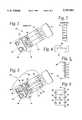
- FIG. 1is a perspective view of a known 9-volt battery which includes six (6) tubular shaped internally series connected 1.5 volt cells, shown with the outer casing removed;
- FIG. 2is a simplified diagram of an alternate embodiment of a known 9-volt battery comprised of a plurality of disc shaped 1.5 volt cells;
- FIG. 3is a perspective view of a multiple cell battery in accordance with the present invention.
- FIG. 4is an end view of an alternative bottom end cap in accordance with the present invention.
- FIG. 5is a schematic representation of the main and auxiliary terminals for the battery illustrated in FIG. 3;
- FIG. 6is a simplified schematic diagram of the charging circuit in accordance with the present invention.
- FIG. 7is a detailed schematic diagram of a battery of charging circuit in accordance with the present invention.
- FIG. 8is a detailed schematic diagram of an alternative embodiment of the battery charging circuit in accordance with the present invention.
- the present inventionrelates to a multiple cell battery and battery charging system for a multiple cell battery which enables a battery formed from multiple series connected battery cells to be charged without overcharging of any of the individual cells due to poor cell voltage matching.
- the battery charging systemin accordance with the present invention, is primarily disclosed and illustrated relative to a 9-volt alkaline battery formed from six (6) 1.5 volt cells internally connected in series, the principles of the present invention are applicable to virtually any type of multiple cell batteries which have relatively poor cell voltage matching characteristics, such as lithium batteries.
- the principles of the present inventionare also applicable to a battery charging system for charging a plurality of externally series connected cells, such as a plurality of AA batteries, to enable in-circuit charging without causing overcharging of any of the series connected cells.
- a conventional 9-volt alkaline batteryis shown with its outer housing removed.
- the batterygenerally identified with the reference numeral 20, is formed from six (6) 1.5 volt alkaline cells 22. These cells 22 are connected in series by way of a plurality of conductive straps 24.
- the positive and negative voltage terminals of the first and last cell 22, respectively, in the series chainare connected to external terminals 26 and 28, by way of electrical conductors 32 such that the voltage across the external terminals 26 and 28 is the sum of all of the cell voltages within the battery.
- a top end cap 30 and a bottom end cap 34are used to close the top and bottom of an external housing (not shown); normally disposed around the cells 22.
- the external terminals 26 and 28are rigidly secured to the top end cap 30.
- FIG. 1illustrates a known 9-volt battery formed from individual elongated tubular cells 22.
- FIG. 2illustrates an alternative construction of a known 9-volt battery wherein each of the individual cells 24 are formed in a disc shape and stacked one on top of the other, thus obviating the need for the conductive straps 24.
- the individual terminals of the cells 22are directly connected to one another to form the series connection.
- alkaline batteriesare known to have inherently poor cell voltage matching characteristics. As such, directing a source of charging current through all of the series connected cells 22 can result in overcharging of one or more of cells 22 within the battery. More particularly, due to the poor cell matching characteristics of alkaline batteries, sourcing a charging current through a series connected batteries would result in the cells becoming fully charged at different rates. As such, certain cells would become fully charged before the other cells. By allowing the charging current to continue to flow through all of the series connected cells in such a situation, the cells which first became fully charged would eventually overcharge and possibly become damaged.
- FIG. 3illustrates a multiple cell battery 36 in accordance with the present invention which enables the battery 36 to be charged while virtually eliminating the risk of overcharging individual cells 22 within the battery 36.
- the battery 36is formed in a conventional manner with a plurality of cells 22 connected in series by way of conductive straps 24.
- the battery 36further includes an outer housing (not shown) opened at both ends and closed by the end caps 30 and 34.
- the positive and negative terminals of the first and last cell 22, respectively, in the series chainare connected to the external terminals 26 and 28 as discussed above.
- the junction of the positive and negative terminals of each of the intermediate cells 22are connected to auxiliary external terminals 38, illustrated schematically in FIG. 5, by way of electrical conductors 39.
- the auxiliary terminals 38may be carried by the top end cap 30, as illustrated in FIG. 3, adjacent the main external terminals 26 and 28.
- the external auxiliary terminals 39may be carried by the batteries end cap 34 as illustrated in FIG. 4 and, similarly, connected to the positive and negative terminals of the intermediate cells 22 by way of the electrical conductors 39.
- the plane of the auxiliary terminals 39may be recessed from the plane of the bottom end cap 34 to reduce the risk of cell shorting when the cell is placed on a conductive surface.
- FIG. 7illustrates a simplified representation of the battery charging circuit in accordance with the present invention whereas FIG. 7 represents a detailed embodiment of the battery charging circuit in accordance with the present invention.
- the charging circuithas only been shown for charging three (3) cells 22.
- the principles of the present inventionare clearly applicable to charging any number of series connected battery cells 22.
- auxiliary terminals 38enable shunt regulators 40, shown as Zener diodes for simplicity, to be connected in parallel across each of the series connected cells 22.
- Alkaline battery cells 22are known to be fully charged when their terminal voltage is about 1.65 volts.
- the shunt regulator 40must be selected to shunt the charging current around the cell 22 whenever the cell voltage exceeds about 1.65 volts DC.
- Zener diodes with such low breakdown voltagesare relatively inaccurate. As such, use of such Zener diodes in such an application can still result overcharging and possibly damage to one or more of the cells 22 within the battery.
- the circuit disclosed in FIG. 7solves this problem by providing a relatively more accurate control of the current shunting around the cell 22 when the cell is fully charged.
- the battery charging circuit in accordance with the present inventionis shown for simplicity for charging three (3) cells.
- the circuitryincludes a plurality of shunt regulators 50 which enable the charging current to the three (3) cells shown 22 to be shunted around individual cells as they become fully charged.
- Each of the shunt regulators 50includes a field effect transistor (FET) 51 whose drain and source terminals are connected in parallel across each of the cells 22.
- FETfield effect transistor
- Each shunt regulator 50is under the control of a voltage sensing circuit 52 which includes a differential amplifier 54 which senses the actual cell voltage (V 1 , V 2 or V 3 ) of the cell 22 and compares it with a reference voltage V REF .
- the reference voltage V REFis developed by a circuit identified within the dash box with the reference numeral 56.
- the outputs of the differential amplifiers 54are used to control the gates of the FETs 51. If the actual cell voltage (V 1 , V 2 or V 3 ) measured at the cell 22 is greater than the reference voltage V REF , the output of the differential amplifier 54 will be positive to switch the shunt regulator 50 on by turning the FET 51 on to enable the charging current to be shunted around that particular cell 22.
- V 1 , V 2 or V 3the output of the differential amplifier 54 will be negative keeping the shunt regulators 50 off. During this condition, the charging current will flow through those cells 22 which have not been shunted.
- a plurality of isolation switches 56which may be FETs, are provided to disconnect the cells 22 from the battery charging circuit to prevent the battery charging circuit from discharging the cells 22 when the charger is not being utilized.
- a resistor 68is connected to the gate terminals of each of the isolation switches 56 by way of their respective scaling resistors 64.
- the isolation switches 56are configured to prevent the cells 22 from being discharged by way of the serially connected resistors 66 and 84 when the battery charger is not being used.
- the drain and source terminals of each of the isolation switches 56is connected between the positive terminal of each cell and the resistor 66.
- the gate terminal of each of the isolation switches 76is under the control of the input charging voltage supply V s .
- a charging voltage supply 58which provides a charging voltage V s , is used to develop a charging current I charge by way of a resistor 60 to charge each of the series connected cells 22.
- the gate terminal of each of the isolation switches 56may be connected to the supply voltage V s by way of a plurality of resistors 62 and 64, which form a voltage divider to control the operation of the isolation switch 56.
- the supply voltage V smay be provided by way of a conventional alternating current (AC) adapter 67, such as a Model No. SA35-3123, as manufactured by Astec, with a direct current (DC) output, such as 16 VDC.
- the AC adapter 67provides a charging current I charge to charge the series connected cells 22.
- a current limiting resistor 60 and an input diode 61are provided.
- the current limiting resistor 60limits the charging current to the cells 22 as well as the battery charging circuitry.
- the input protection diode 61prevents the isolation switches 56 from being turned on by the battery cells 22.
- the supply voltage V s input to the battery charging circuitis under the control of the switching circuit 58 which may include a FET 69, a bipolar junction transistor (BJT) 71 and four resistors 73, 75, 77 and 79.
- the FET 69is used to connect and disconnect the output of the AC adapter 67 to the battery charging circuitry.
- the FET 69is under the control of the BJT 71, which, in turn, is under the control of a CONTROL INPUT.
- the CONTROL INPUTmay be an output from a microprocessor or any chip that can provide a logical high and low output. When the CONTROL INPUT is high, the gate of the FET 69 is pulled low to disconnect the AC adapter 67 from the battery charging circuit. Alternatively, when the CONTROL INPUT is low, the gate of the FET 69 will be high to connect the AC adapter 67 to the battery charging circuitry.
- the reference voltage V REFis developed by the circuit identified within the dash box 56 which includes a differential amplifier 70, a plurality of serially connected resistors 72, 74 and 76, and a Zener diode 78.
- the resistors 72, 74 and 76form a voltage divider to divide the voltage from the power supply voltage V s to develop a cell voltage V cell that is applied to the positive terminal of the differential amplifier 70.
- the Zener diode 78regulates the voltage applied to the positive input of the differential amplifier 70.
- the output of the differential amplifier 70is connected to its negative input to form a unity gain buffer to provide an output voltage V REF , virtually identical to the regulated voltage applied to the positive terminal of the differential amplifier 70.
- This output voltage V REFis applied to the negative inputs of each of the difference amplifiers 54 by way of scaling resistors 80.
- These scaling resistors 80in conjunction with resistors 82, connected between the negative junction of the difference amplifiers 54 and ground, enable the reference voltage V REF to be scaled to a predetermined value at the negative input of each of the difference amplifiers 54.
- the actual cell voltages (V 1 , V 2 or V 3 ), applied to the positive inputs of each of the difference amplifiers 54may likewise be scaled by way of the respective scaling resistors 66 and 84, connected between the positive input of the difference amplifiers 54 and ground.
- the values of the scaling resistor pairs 66 and 82, as well as 80 and 84should be equal.
- the circuitry illustrated in FIG. 7can be formed as a printed circuit board (PCB) and incorporated within a multiple cell battery housing.
- PCBprinted circuit board
- the PCB incorporating the battery charging circuit illustrated in FIG. 7may be formed as the bottom end cap 34 illustrated in FIG. 3.
- the circuitry disclosed in FIG. 7could be incorporated into a flexible PCB and used to form the outer housing around the battery.
- external auxiliary contacts 38would not be required since the required connections between the positive and negative terminals of each of the respective cells 22 could be made within the battery housing.
- the batterywould be formed with only two external terminals 26 and 28 to enable the battery to be connected in a circuit or, alternatively, to external source charging voltage or current.
- FIG. 8An alternative embodiment of the battery charging circuit is illustrated in FIG. 8.
- a voltage source 102, 104 or 106is connected across each of the serially connected battery cells 22.
- Each of the voltage sources 102, 104 and 106is adapted to source current to its associated battery cell 22 during a charging condition.
- two of the voltage sources 104 and 106are also adapted to sink current to prevent overcharging of certain of the battery cells 22.
- the voltage source 102is a floating voltage source and sources charging current anytime the battery cell 22 connected between nodes V 2 and V 3 is less than a desired voltage. Since the voltage source 102 is connected to the first battery cell 22 in the serially connected chain, it is not necessary for the voltage source 102 to silk current during any of the conditions. However, the voltage sources 104 and 106 must be able to source current for charging and additionally sink current to prevent overcharging of various of the downstream battery cells 22.
- Each of the voltage sources 102, 104 and 106is configured as a differential amplifier which includes an operational amplifier 108 and 2 to 4 input scaling resistors 110, 112, 114 and 116.
- the voltage source 102is connected across the battery cell 22 disposed the nodes V 2 and V 3 .
- the negative terminal of the differential amplifier 108is connected to the positive terminal of the battery cell 22 and referenced to a reference voltage V REF by way of the resistors 110 and 112.
- the positive terminal of the differential amplifier 108is connected to the negative terminal of the battery cell 22 connected between the nodes V 2 and V 3 , and referenced to ground by way of the input scaling resistors 114 and 116.
- the voltage source 102will float and charge the battery cell 22 (connected between the nodes V 2 and V 3 ) any time the voltage across that cell 22 falls below the reference voltage V REF . More particularly, the voltage applied to the positive terminal of the differential amplifier 108 is connected to the negative terminal of the battery cell 22 which coincides with the node V 2 .
- the voltage at the node V 2is equal to the sum of the cell voltages connected between the node V 2 and ground. During ideal conditions (i.e., cells fully charged), the voltage at the node V 2 will be twice the reference voltage V REF .
- the voltage applied to the negative terminal of the differential amplifier 108is the positive terminal of the battery cell 22 connected between the nodes V 2 and V 3 , referenced to a reference voltage V REF .
- the node voltage V 3will be three times the reference voltage V REF .
- the voltage applied to the negative terminal of the differential amplifier 108is referenced to the reference voltage V REF , the voltage applied to the negative terminal of the differential amplifier 108 will only be twice V REF during ideal conditions.
- the differential amplifier 108By sizing the resistors 110, 112, 114 and 116 to have the same value, the differential amplifier 108 will track the voltage across the battery cell 22 connected between the nodes V 2 and V 3 such that any time the voltage of that cell 22 falls below V REF , the output voltage of the differential amplifier 108 will go positive and provide a charging current to the cell 22 connected between the nodes V 2 and V 3 .
- a current limiting resistor 118is connected between the output of the differential amplifier 108 and the positive cell terminal.
- An important aspect of the circuitry illustrated in FIG. 8is that once the downstream cells 22 (i.e., connected between the node V 2 and ground become fully charged) before the cell connected between the nodes V 2 and V 3 becomes fully charged, the voltage sources 104 and 106 act to sink the charging current sourced by the voltage source 102 which normally would flow through all three of the serially connected battery cells in order to prevent overcharging of any fully charged cells connected downstream. Since the voltage source 102 is connected to the first cell in the series connected string, the voltage source 102 does not sink current during any condition.
- the differential amplifier 108 that forms a portion of the voltage source 104is connected across the battery cell 22, connected between the nodes V 1 and V 2 .
- the negative terminal of the differential amplifier 108 of the voltage source 104is connected to the plus positive terminal of the battery cell 22 connected between the nodes V 1 and V 2 referenced to the reference voltage V REF .
- the positive terminal of the differential amplifier 108is connected to the negative terminal of the battery cell 22 connected between the nodes V 1 and V 2 , referenced to ground.
- the voltage applied to the negative terminal of the differential amplifier 108is equal to the node voltage V 2 .
- This node voltage V 2is equal to the algebraic sum of the two serially connected battery cells 22 connected between the node V 2 and ground.
- the voltage applied to the negative terminal of the differential amplifier 108is referenced to V REF , the voltage applied at the input of the negative terminal will be V 2 minus V REF .
- this voltagewill be 1/2 V 2 minus V REF .
- the voltage applied to the negative terminal of the differential amplifier 108will be V REF .
- the voltage applied to the positive terminal of the differential amplifier 108will be V 1 .
- the voltage applied to the positive terminal of the differential amplifier 108will be 1/2 V 1 , since the positive terminal is referenced to ground.
- the voltage source 104will monitor the voltage across the cell connected between the nodes V 1 and V 2 and provide a positive output voltage anytime that cell voltage falls below V REF .
- the differential amplifier 108will output a positive voltage in order to provide a charging current which will nominally flow through the two serially connected battery cells 22 connected between the node V 2 and ground.
- each of the voltage sources 104 and 106is able to sink current as well as source current.
- the voltage source 104will sink the charging current flowing through the battery cell 22 connected between the nodes V 2 and V 3 through to ground by way of the output of its differential amplifier 108 since the voltage at the positive terminal of the battery cell connected to the node V 2 will be relatively more positive relative to the output of the differential amplifier 108.
- sinking the charging currentduring such a condition, the battery cell connected between the nodes V 1 and V 2 will not become overcharged.
- an additional networkmay be provided for the voltage source 104, as well as the voltage source 106, which provides a different resistance for the voltage source 104 in a current sinking mode as opposed to a current sourcing mode.
- a diode 120 and serially connected resistor 122may be connected in parallel with each of the current limiting resistors 118 for the voltage sources 104 and 106.
- the effective resistance for the voltage sources 104 and 106will be equivalent to the value of the current limiting resistance 118 in a current sourcing mode.
- the diodes 120will be biased such that the resistance in a current sinking mode is equivalent to the resistance of the parallel combination of the resistances 122 and 118.
- the voltage source 106is similar to the voltage sources 102 and 104 except the positive terminal of its differential amplifier 108 is referenced to ground. As such, there is no need for the input scaling resistors 114 and 116 on the voltage source 106.
- the negative terminal of the differential amplifier 108is connected to the positive terminal of the battery cell 22 connected between the node V 1 and ground. The negative terminal is referenced to the reference voltage V REF .
- V REFthe reference voltage
- the input to the negative terminal of the differential amplifier 108will be equivalent to 1/2 the difference of V 1 minus V REF .
- ground potentialwill be applied to the negative terminal of the differential amplifier 108.
- the differential amplifier 108 of the voltage source 106will provide a positive output which will provide a charging current to charge the battery cell 22 connected between the node V 1 and ground. Should the battery cell 22 connected between V 1 and ground become fully charged prior to any of the remaining cells, the voltage source 106 will sink current to ground by way of the output of the differential amplifier 108 in a manner as discussed above.
- the input scaling resistors 110, 112, 114 and 116are selected to be equal in value, whenever the reference voltage V REF is selected to be equivalent to the desired cell voltage when the cell is fully charged.
- V REFreference voltage
- principles of the present inventionare applicable to any reference voltage.
- the values of the scaling resistors 110, 112, 114 and 116would have to be adjusted accordingly.
- a plurality of isolation switches 124are provided to disconnect the battery cells from the circuitry during such a condition.
- Each of the isolation switches 124is configured as a field effect transistor (FET) having source, drain and gate terminals. The gate terminals of each of the FETs 124 are connected together and connected to the charging supply voltage V in .
- FETfield effect transistor
- the FETs 124will all be on to connect the battery cells 22 to the circuitry illustrated in FIG. 8. If the supply voltage V in is removed, the FETs 124 will turn off in order to disconnect the battery cells 22 from the circuitry illustrated in FIG. 8.
- a resistor 126is connected between the gates of each of the FETs 124 and ground. This resistor 126 is used to discharge any gate capacitance in the FETs 124.
Landscapes
- Engineering & Computer Science (AREA)
- Power Engineering (AREA)
- Manufacturing & Machinery (AREA)
- Chemical & Material Sciences (AREA)
- Chemical Kinetics & Catalysis (AREA)
- Electrochemistry (AREA)
- General Chemical & Material Sciences (AREA)
- Charge And Discharge Circuits For Batteries Or The Like (AREA)
Abstract
Description
Claims (24)
Priority Applications (1)
| Application Number | Priority Date | Filing Date | Title |
|---|---|---|---|
| US08/785,474US5747964A (en) | 1994-02-22 | 1997-01-17 | Rechargeable battery and charging system |
Applications Claiming Priority (2)
| Application Number | Priority Date | Filing Date | Title |
|---|---|---|---|
| US20001594A | 1994-02-22 | 1994-02-22 | |
| US08/785,474US5747964A (en) | 1994-02-22 | 1997-01-17 | Rechargeable battery and charging system |
Related Parent Applications (1)
| Application Number | Title | Priority Date | Filing Date |
|---|---|---|---|
| US20001594AContinuation | 1994-02-22 | 1994-02-22 |
Publications (1)
| Publication Number | Publication Date |
|---|---|
| US5747964Atrue US5747964A (en) | 1998-05-05 |
Family
ID=22739961
Family Applications (2)
| Application Number | Title | Priority Date | Filing Date |
|---|---|---|---|
| US08/767,170Expired - LifetimeUS5821733A (en) | 1994-02-22 | 1996-12-16 | Multiple cell and serially connected rechargeable batteries and charging system |
| US08/785,474Expired - LifetimeUS5747964A (en) | 1994-02-22 | 1997-01-17 | Rechargeable battery and charging system |
Family Applications Before (1)
| Application Number | Title | Priority Date | Filing Date |
|---|---|---|---|
| US08/767,170Expired - LifetimeUS5821733A (en) | 1994-02-22 | 1996-12-16 | Multiple cell and serially connected rechargeable batteries and charging system |
Country Status (1)
| Country | Link |
|---|---|
| US (2) | US5821733A (en) |
Cited By (30)
| Publication number | Priority date | Publication date | Assignee | Title |
|---|---|---|---|---|
| WO2000016462A1 (en)* | 1998-09-17 | 2000-03-23 | Qualcomm Incorporated | Battery pack controller |
| US6100243A (en)* | 1994-09-06 | 2000-08-08 | La Jolla Cancer Research Foundation | Method of sensitizing tumor cells with adenovirus E1A |
| US6172479B1 (en) | 1999-03-04 | 2001-01-09 | Baxter International Inc. | Battery control circuit |
| US6268714B1 (en)* | 1999-05-07 | 2001-07-31 | Tai-Her Yang | Voltage limiting circuit connected in parallel with a battery set and including a series-connected impedance which permits linear adjustments |
| US6459243B1 (en) | 2001-12-14 | 2002-10-01 | Zinc Matrix Power, Inc. | Multiple plateau battery charging method and system to fully charge the first plateau |
| US6522102B1 (en) | 2001-12-14 | 2003-02-18 | Zinc Matrix Power, Inc. | Multiple plateau battery charging method and system to charge to the second plateau |
| US20030090234A1 (en)* | 2001-11-09 | 2003-05-15 | Glasgow Kevin L. | Battery charger |
| US20030111979A1 (en)* | 2001-12-16 | 2003-06-19 | Michael Cheiky | Battery charging system |
| WO2003096471A1 (en)* | 2002-05-09 | 2003-11-20 | Moby Power Co., Ltd | Rechargeable battery pack |
| US20030234752A1 (en)* | 2002-06-24 | 2003-12-25 | Turnbull Robert R. | Electrochromic element drive control circuit |
| US20040248001A1 (en)* | 2003-06-03 | 2004-12-09 | Hall David R. | Pressure-compensated downhole battery |
| US20050024021A1 (en)* | 2003-05-07 | 2005-02-03 | Milwaukee Electric Tool Corporation | Battery charger and assembly |
| US20050237025A1 (en)* | 2004-04-24 | 2005-10-27 | Alexander Osswald | Charger for a rechargeable battery |
| US20060113956A1 (en)* | 2003-05-07 | 2006-06-01 | Bublitz Scott D | Battery charger and assembly |
| WO2005124963A3 (en)* | 2004-06-22 | 2006-06-08 | A1 Light And More Lichttechnik | Energy storage device |
| USD529439S1 (en) | 2002-05-07 | 2006-10-03 | Milwaukee Electric Tool Corporation | Battery charger |
| US20070252556A1 (en)* | 2006-04-27 | 2007-11-01 | Dorian West | System and method for interconnection of battery packs |
| US20110175571A1 (en)* | 2007-10-19 | 2011-07-21 | Troy Renken | Charger and method for charging for silver zinc batteries |
| CN102668307A (en)* | 2009-10-21 | 2012-09-12 | K2能源解决方案有限公司 | Circuitry for balancing charging of series connected battery cells |
| US20130207613A1 (en)* | 2006-11-10 | 2013-08-15 | Lithium Balance A/S | Battery management system |
| US9240696B2 (en) | 2010-07-15 | 2016-01-19 | Zpower, Llc | Method and apparatus for recharging a battery |
| EP2441153B1 (en)* | 2009-06-12 | 2018-08-08 | Nissan Motor Co., Ltd. | Charge control device and method for secondary battery module |
| US20190058335A1 (en)* | 2016-05-02 | 2019-02-21 | Bayerische Motoren Werke Aktiengesellschaft | Rechargeable Battery Arrangement with Improved Symmetrization |
| US10291051B2 (en) | 2013-01-11 | 2019-05-14 | Zpower, Llc | Methods and systems for recharging a battery |
| US10547189B2 (en) | 2015-04-29 | 2020-01-28 | Zpower, Llc | Temperature dependent charge algorithm |
| US20220360091A1 (en)* | 2021-05-04 | 2022-11-10 | Exro Technologies Inc. | Battery Control Systems and Methods |
| US11722026B2 (en) | 2019-04-23 | 2023-08-08 | Dpm Technologies Inc. | Fault tolerant rotating electric machine |
| US11967913B2 (en) | 2021-05-13 | 2024-04-23 | Exro Technologies Inc. | Method and apparatus to drive coils of a multiphase electric machine |
| US12088176B2 (en) | 2021-07-08 | 2024-09-10 | Exro Technologies Inc. | Dynamically reconfigurable power converter utilizing windings of electric machine |
| US12176836B2 (en) | 2018-09-05 | 2024-12-24 | Dpm Technologies Inc. | Systems and methods for intelligent energy storage and provisioning using an energy storage control system |
Families Citing this family (65)
| Publication number | Priority date | Publication date | Assignee | Title |
|---|---|---|---|---|
| US5982144A (en)* | 1997-07-14 | 1999-11-09 | Johnson Research & Development Company, Inc. | Rechargeable battery power supply overcharge protection circuit |
| US6025696A (en)* | 1998-03-27 | 2000-02-15 | Space Systems/Loral, Inc. | Battery cell bypass module |
| US6326767B1 (en) | 1999-03-30 | 2001-12-04 | Shoot The Moon Products Ii, Llc | Rechargeable battery pack charging system with redundant safety systems |
| US6242129B1 (en) | 1999-04-02 | 2001-06-05 | Excellatron Solid State, Llc | Thin lithium film battery |
| US6398824B1 (en) | 1999-04-02 | 2002-06-04 | Excellatron Solid State, Llc | Method for manufacturing a thin-film lithium battery by direct deposition of battery components on opposite sides of a current collector |
| US6511516B1 (en) | 2000-02-23 | 2003-01-28 | Johnson Research & Development Co., Inc. | Method and apparatus for producing lithium based cathodes |
| US6582481B1 (en) | 1999-11-23 | 2003-06-24 | Johnson Research & Development Company, Inc. | Method of producing lithium base cathodes |
| US6387563B1 (en) | 2000-03-28 | 2002-05-14 | Johnson Research & Development, Inc. | Method of producing a thin film battery having a protective packaging |
| US6423106B1 (en) | 2000-04-05 | 2002-07-23 | Johnson Research & Development | Method of producing a thin film battery anode |
| US6402796B1 (en) | 2000-08-07 | 2002-06-11 | Excellatron Solid State, Llc | Method of producing a thin film battery |
| US20020110733A1 (en)* | 2000-08-07 | 2002-08-15 | Johnson Lonnie G. | Systems and methods for producing multilayer thin film energy storage devices |
| WO2002029836A1 (en)* | 2000-10-02 | 2002-04-11 | Andelman Marc D | Fringe-field capacitor electrode for electrochemical device |
| US6452363B1 (en) | 2000-12-28 | 2002-09-17 | C. E. Niehoff & Co. | Multiple battery charge equalizer |
| US6388423B1 (en) | 2001-02-23 | 2002-05-14 | John W. Schilleci, Jr. | Battery monitor and open circuit protector |
| JP3554714B2 (en)* | 2001-05-31 | 2004-08-18 | 長野日本無線株式会社 | Current cutoff circuit of storage element |
| US20040121204A1 (en)* | 2001-06-07 | 2004-06-24 | Adelman Marc D. | Fluid electrical connected flow-through electrochemical cells, system and method |
| US20070094865A1 (en)* | 2002-01-10 | 2007-05-03 | Ji-Guang Zhang | Packaged thin film batteries and methods of packaging thin film batteries |
| US7204862B1 (en) | 2002-01-10 | 2007-04-17 | Excellatron Solid State, Llc | Packaged thin film batteries and methods of packaging thin film batteries |
| US7960054B2 (en)* | 2002-01-10 | 2011-06-14 | Excellatron Solid State Llc | Packaged thin film batteries |
| US6798170B2 (en)* | 2002-02-08 | 2004-09-28 | Valence Technology, Inc. | Electrical power source apparatuses, circuits, electrochemical device charging methods, and methods of charging a plurality of electrochemical devices |
| US6724173B2 (en)* | 2002-02-08 | 2004-04-20 | Valence Technology, Inc. | Circuits, apparatuses, electrochemical device charging methods, and lithium-mixed metal electrode cell charging methods |
| US7599484B2 (en)* | 2002-04-29 | 2009-10-06 | Adc Dsl Systems, Inc. | Element management system for managing line-powered network elements |
| US7567665B2 (en)* | 2002-04-29 | 2009-07-28 | Adc Dsl Systems, Inc. | Function for controlling line powered network element |
| US6806686B1 (en) | 2003-04-25 | 2004-10-19 | Maxwell Technologies, Inc. | Charge balancing circuit |
| JP2006524980A (en)* | 2003-04-25 | 2006-11-02 | マックスウェル テクノロジーズ, インク | Charge balancing circuit for double layer capacitor |
| US6886240B2 (en)* | 2003-07-11 | 2005-05-03 | Excellatron Solid State, Llc | Apparatus for producing thin-film electrolyte |
| US6852139B2 (en)* | 2003-07-11 | 2005-02-08 | Excellatron Solid State, Llc | System and method of producing thin-film electrolyte |
| US20050076551A1 (en)* | 2003-08-11 | 2005-04-14 | Aaron Silverstone | Solar illuminated address sign |
| US20050170256A1 (en)* | 2004-01-30 | 2005-08-04 | John Cummings | Electrical power source apparatuses, electrical power source operational methods, and electrochemical device charging methods |
| US7719227B2 (en)* | 2004-02-13 | 2010-05-18 | Valence Technology, Inc. | Electrical energy supply methods and electrical energy power supplies |
| US20080070087A1 (en)* | 2004-02-20 | 2008-03-20 | Excellatron Solid State, Llc | Non-volatile cathodes for lithium oxygen batteries and method of producing same |
| US7691536B2 (en)* | 2004-02-20 | 2010-04-06 | Excellatron Solid State, Llc | Lithium oxygen batteries and method of producing same |
| US10566669B2 (en) | 2004-02-20 | 2020-02-18 | Johnson Ip Holding, Llc | Lithium oxygen batteries having a carbon cloth current collector and method of producing same |
| US7253586B2 (en)* | 2004-03-11 | 2007-08-07 | Lenovo (Singapore) Pte. Ltd. | Intelligent multiple battery charging station |
| US7696089B1 (en) | 2004-05-11 | 2010-04-13 | Johnson Research & Development Co., Inc. | Passivated thin film and method of producing same |
| US8436583B2 (en) | 2004-06-09 | 2013-05-07 | Icc-Nexergy, Inc. | Multiple cell battery charger configured with a parallel topology |
| US7394225B2 (en)* | 2004-06-09 | 2008-07-01 | International Components Corporation | Pseudo constant current multiple cell battery charger configured with a parallel topology |
| US8568921B1 (en) | 2004-08-18 | 2013-10-29 | Excellatron Solid State Llc | Regenerative ion exchange fuel cell |
| CA2517188A1 (en)* | 2004-08-26 | 2006-02-26 | Pure Energy Visions Inc. | Rechargeable alkaline battery with overcharging protection |
| EP1641099A1 (en)* | 2004-09-24 | 2006-03-29 | Conception et Développement Michelin S.A. | Detachable charge control circuit for balancing the voltage of supercapacitors connected in series |
| US7199488B1 (en)* | 2004-10-14 | 2007-04-03 | Baker David A | Telemetry power system |
| US7928691B2 (en)* | 2004-11-10 | 2011-04-19 | EaglePicher Technologies | Method and system for cell equalization with isolated charging sources |
| US20060097700A1 (en)* | 2004-11-10 | 2006-05-11 | Eaglepicher Technologies, Llc | Method and system for cell equalization with charging sources and shunt regulators |
| US20060097697A1 (en)* | 2004-11-10 | 2006-05-11 | Eaglepicher Technologies, Llc | Method and system for cell equalization with switched charging sources |
| JP2009524900A (en)* | 2005-10-11 | 2009-07-02 | エクセラトロン ソリッド ステート,エルエルシー | Lithium battery manufacturing method |
| WO2007106742A2 (en) | 2006-03-10 | 2007-09-20 | Excellatron Solid State Llc | Air battery and manufacturing method |
| JP5169002B2 (en)* | 2007-04-20 | 2013-03-27 | ソニー株式会社 | Battery system and manufacturing method thereof |
| US9034525B2 (en)* | 2008-06-27 | 2015-05-19 | Johnson Ip Holding, Llc | Ionically-conductive amorphous lithium lanthanum zirconium oxide |
| US20120196189A1 (en) | 2007-06-29 | 2012-08-02 | Johnson Ip Holding, Llc | Amorphous ionically conductive metal oxides and sol gel method of preparation |
| US8211496B2 (en)* | 2007-06-29 | 2012-07-03 | Johnson Ip Holding, Llc | Amorphous lithium lanthanum titanate thin films manufacturing method |
| US20090092903A1 (en)* | 2007-08-29 | 2009-04-09 | Johnson Lonnie G | Low Cost Solid State Rechargeable Battery and Method of Manufacturing Same |
| US20090239132A1 (en)* | 2008-03-20 | 2009-09-24 | Excellatron Solid State, Llc | Oxygen battery system |
| AU2009229167B2 (en) | 2008-03-27 | 2014-01-23 | Zpower, Llc | Electrode separator |
| JP4771180B2 (en)* | 2008-08-28 | 2011-09-14 | トヨタ自動車株式会社 | Battery pack and battery pack control system |
| US9005788B2 (en) | 2009-07-06 | 2015-04-14 | Amperex Technology Limited | Management scheme for multiple battery cells |
| US20100141210A1 (en)* | 2009-12-07 | 2010-06-10 | Remy Technologies, L.L.C. | Alternator for charging multiple electric storage devices |
| US8866412B2 (en) | 2011-01-11 | 2014-10-21 | Braxton Engineering, Inc. | Source and multiple loads regulator |
| CN104321914B (en) | 2012-03-01 | 2019-08-13 | 约翰逊Ip控股有限责任公司 | High-capacity solid-state composite positive electrode, solid-state composite separator, solid-state rechargeable lithium battery and manufacturing method thereof |
| US9793525B2 (en) | 2012-10-09 | 2017-10-17 | Johnson Battery Technologies, Inc. | Solid-state battery electrodes |
| CN104124726B (en) | 2013-04-25 | 2016-08-31 | 财团法人工业技术研究院 | Charging device and charging method |
| GB2528290A (en)* | 2014-07-16 | 2016-01-20 | John Leslie Gordon Hardy | Battery management |
| CN108604665B (en) | 2015-12-21 | 2022-04-22 | 约翰逊Ip控股有限公司 | Solid state battery, separator, electrode and method of manufacture |
| US10218044B2 (en) | 2016-01-22 | 2019-02-26 | Johnson Ip Holding, Llc | Johnson lithium oxygen electrochemical engine |
| US10720614B2 (en) | 2018-09-28 | 2020-07-21 | Daniel Francis Roddy | Portable modular energy storage |
| US10573859B2 (en) | 2018-07-03 | 2020-02-25 | Daniel Francis Roddy | Portable modular energy storage |
Citations (5)
| Publication number | Priority date | Publication date | Assignee | Title |
|---|---|---|---|---|
| US4238721A (en)* | 1979-02-06 | 1980-12-09 | The United States Of America As Represented By The United States Department Of Energy | System and method for charging electrochemical cells in series |
| US4303877A (en)* | 1978-05-05 | 1981-12-01 | Brown, Boveri & Cie Aktiengesellschaft | Circuit for protecting storage cells |
| US4713597A (en)* | 1985-12-04 | 1987-12-15 | Powerplex Technologies, Inc. | Silicon diode looping element for protecting a battery cell |
| US5206577A (en)* | 1991-09-30 | 1993-04-27 | Fish Robert D | Battery charger |
| US5270635A (en)* | 1989-04-11 | 1993-12-14 | Solid State Chargers, Inc. | Universal battery charger |
- 1996
- 1996-12-16USUS08/767,170patent/US5821733A/ennot_activeExpired - Lifetime
- 1997
- 1997-01-17USUS08/785,474patent/US5747964A/ennot_activeExpired - Lifetime
Patent Citations (5)
| Publication number | Priority date | Publication date | Assignee | Title |
|---|---|---|---|---|
| US4303877A (en)* | 1978-05-05 | 1981-12-01 | Brown, Boveri & Cie Aktiengesellschaft | Circuit for protecting storage cells |
| US4238721A (en)* | 1979-02-06 | 1980-12-09 | The United States Of America As Represented By The United States Department Of Energy | System and method for charging electrochemical cells in series |
| US4713597A (en)* | 1985-12-04 | 1987-12-15 | Powerplex Technologies, Inc. | Silicon diode looping element for protecting a battery cell |
| US5270635A (en)* | 1989-04-11 | 1993-12-14 | Solid State Chargers, Inc. | Universal battery charger |
| US5206577A (en)* | 1991-09-30 | 1993-04-27 | Fish Robert D | Battery charger |
Non-Patent Citations (6)
| Title |
|---|
| "234-1098 (OEA-151) Power Supply Code Sequence", Zenith Data Systems, Apr. 1991. |
| "A.C. Power Supply Model No. 55,924, Part No. 234-1098", Zenith Data Systems, Apr. 1992. |
| "Sealed Rechargeable Batteries Application Manual", Gates Energy Products, 1989, pp. 150-162. |
| 234 1098 (OEA 151) Power Supply Code Sequence , Zenith Data Systems, Apr. 1991.* |
| A.C. Power Supply Model No. 55,924, Part No. 234 1098 , Zenith Data Systems, Apr. 1992.* |
| Sealed Rechargeable Batteries Application Manual , Gates Energy Products, 1989, pp. 150 162.* |
Cited By (55)
| Publication number | Priority date | Publication date | Assignee | Title |
|---|---|---|---|---|
| US6100243A (en)* | 1994-09-06 | 2000-08-08 | La Jolla Cancer Research Foundation | Method of sensitizing tumor cells with adenovirus E1A |
| US6544955B1 (en) | 1994-09-06 | 2003-04-08 | The Burnham Institute | Method of sensitizing tumor cells with adenovirus E1A |
| WO2000016462A1 (en)* | 1998-09-17 | 2000-03-23 | Qualcomm Incorporated | Battery pack controller |
| US6172479B1 (en) | 1999-03-04 | 2001-01-09 | Baxter International Inc. | Battery control circuit |
| US6268714B1 (en)* | 1999-05-07 | 2001-07-31 | Tai-Her Yang | Voltage limiting circuit connected in parallel with a battery set and including a series-connected impedance which permits linear adjustments |
| US20080100261A1 (en)* | 2001-11-09 | 2008-05-01 | Glasgow Kevin L | Battery charger |
| US20030090234A1 (en)* | 2001-11-09 | 2003-05-15 | Glasgow Kevin L. | Battery charger |
| US7332889B2 (en) | 2001-11-09 | 2008-02-19 | Milwaukee Electric Tool Corporation | Battery charger |
| US6459243B1 (en) | 2001-12-14 | 2002-10-01 | Zinc Matrix Power, Inc. | Multiple plateau battery charging method and system to fully charge the first plateau |
| US6522102B1 (en) | 2001-12-14 | 2003-02-18 | Zinc Matrix Power, Inc. | Multiple plateau battery charging method and system to charge to the second plateau |
| US6943530B2 (en) | 2001-12-16 | 2005-09-13 | Zinc Matrix Power, Inc. | Battery charging system |
| US20040178772A1 (en)* | 2001-12-16 | 2004-09-16 | Michael Cheiky | Battery charging system |
| US20040217738A1 (en)* | 2001-12-16 | 2004-11-04 | Michael Cheiky | Battery charging system |
| US6943529B2 (en) | 2001-12-16 | 2005-09-13 | Zinc Matrix Power, Inc. | Battery charging system |
| US20030111979A1 (en)* | 2001-12-16 | 2003-06-19 | Michael Cheiky | Battery charging system |
| US7218076B2 (en) | 2001-12-16 | 2007-05-15 | Zinc Matrix Power, Inc. | Battery charging system |
| USD529439S1 (en) | 2002-05-07 | 2006-10-03 | Milwaukee Electric Tool Corporation | Battery charger |
| WO2003096471A1 (en)* | 2002-05-09 | 2003-11-20 | Moby Power Co., Ltd | Rechargeable battery pack |
| US20030234752A1 (en)* | 2002-06-24 | 2003-12-25 | Turnbull Robert R. | Electrochromic element drive control circuit |
| US7215318B2 (en) | 2002-06-24 | 2007-05-08 | Gentex Corporation | Electrochromic element drive control circuit |
| US20080036420A1 (en)* | 2003-05-07 | 2008-02-14 | Zeiler Jeffrey M | Battery charger and assembly |
| US7659696B2 (en) | 2003-05-07 | 2010-02-09 | Milwaukee Electric Tool Corporation | Battery charger and assembly |
| US20060113956A1 (en)* | 2003-05-07 | 2006-06-01 | Bublitz Scott D | Battery charger and assembly |
| US20050024021A1 (en)* | 2003-05-07 | 2005-02-03 | Milwaukee Electric Tool Corporation | Battery charger and assembly |
| US7105249B2 (en)* | 2003-06-03 | 2006-09-12 | Hall David R | Pressure-compensated downhole battery |
| US20040248001A1 (en)* | 2003-06-03 | 2004-12-09 | Hall David R. | Pressure-compensated downhole battery |
| GB2414873A (en)* | 2004-04-24 | 2005-12-07 | Bosch Gmbh Robert | Battery charger with disconnection |
| US20050237025A1 (en)* | 2004-04-24 | 2005-10-27 | Alexander Osswald | Charger for a rechargeable battery |
| WO2005124963A3 (en)* | 2004-06-22 | 2006-06-08 | A1 Light And More Lichttechnik | Energy storage device |
| US20070252556A1 (en)* | 2006-04-27 | 2007-11-01 | Dorian West | System and method for interconnection of battery packs |
| US7667432B2 (en)* | 2006-04-27 | 2010-02-23 | Tesla Motors, Inc. | Method for interconnection of battery packs and battery assembly containing interconnected battery packs |
| US7956574B1 (en) | 2006-04-27 | 2011-06-07 | Tesla Motors, Inc. | System and method for interconnection of battery packs |
| US12003124B2 (en) | 2006-11-10 | 2024-06-04 | Lithium Balance A/S | Battery management system |
| US20130207613A1 (en)* | 2006-11-10 | 2013-08-15 | Lithium Balance A/S | Battery management system |
| US10862317B2 (en) | 2006-11-10 | 2020-12-08 | Lithium Balance A/S | Battery management system with temperature sensing and charge management for individual series-connected battery cells |
| US10396570B2 (en)* | 2006-11-10 | 2019-08-27 | Lithium Balance A/S | Battery management system with temperature sensing and charge management for individual series-connected battery cells |
| US20110175571A1 (en)* | 2007-10-19 | 2011-07-21 | Troy Renken | Charger and method for charging for silver zinc batteries |
| EP2441153B1 (en)* | 2009-06-12 | 2018-08-08 | Nissan Motor Co., Ltd. | Charge control device and method for secondary battery module |
| EP2491636A4 (en)* | 2009-10-21 | 2013-08-28 | K2 Energy Solutions Inc | Circuitry for balancing charging of series connected battery cells |
| CN102668307A (en)* | 2009-10-21 | 2012-09-12 | K2能源解决方案有限公司 | Circuitry for balancing charging of series connected battery cells |
| US9240696B2 (en) | 2010-07-15 | 2016-01-19 | Zpower, Llc | Method and apparatus for recharging a battery |
| US11735940B2 (en) | 2013-01-11 | 2023-08-22 | Riot Energy Inc. | Methods and systems for recharging a battery |
| US10291051B2 (en) | 2013-01-11 | 2019-05-14 | Zpower, Llc | Methods and systems for recharging a battery |
| US10547189B2 (en) | 2015-04-29 | 2020-01-28 | Zpower, Llc | Temperature dependent charge algorithm |
| EP3453097A1 (en)* | 2016-05-02 | 2019-03-13 | Bayerische Motoren Werke Aktiengesellschaft | Rechargeable battery arrangement with improved symmetrization |
| US10903662B2 (en)* | 2016-05-02 | 2021-01-26 | Bayerische Motoren Werke Aktiengesellschaft | Rechargeable battery arrangement with improved symmetrization |
| US20190058335A1 (en)* | 2016-05-02 | 2019-02-21 | Bayerische Motoren Werke Aktiengesellschaft | Rechargeable Battery Arrangement with Improved Symmetrization |
| US12176836B2 (en) | 2018-09-05 | 2024-12-24 | Dpm Technologies Inc. | Systems and methods for intelligent energy storage and provisioning using an energy storage control system |
| US11722026B2 (en) | 2019-04-23 | 2023-08-08 | Dpm Technologies Inc. | Fault tolerant rotating electric machine |
| US20220368135A1 (en)* | 2021-05-04 | 2022-11-17 | Exro Technologies Inc. | Battery Control Systems and Methods |
| US11897362B2 (en)* | 2021-05-04 | 2024-02-13 | Exro Technologies Inc. | Systems and methods for individual control of a plurality of controllable units of battery cells |
| US11708005B2 (en)* | 2021-05-04 | 2023-07-25 | Exro Technologies Inc. | Systems and methods for individual control of a plurality of battery cells |
| US20220360091A1 (en)* | 2021-05-04 | 2022-11-10 | Exro Technologies Inc. | Battery Control Systems and Methods |
| US11967913B2 (en) | 2021-05-13 | 2024-04-23 | Exro Technologies Inc. | Method and apparatus to drive coils of a multiphase electric machine |
| US12088176B2 (en) | 2021-07-08 | 2024-09-10 | Exro Technologies Inc. | Dynamically reconfigurable power converter utilizing windings of electric machine |
Also Published As
| Publication number | Publication date |
|---|---|
| US5821733A (en) | 1998-10-13 |
Similar Documents
| Publication | Publication Date | Title |
|---|---|---|
| US5747964A (en) | Rechargeable battery and charging system | |
| KR100624944B1 (en) | Battery pack protection circuit | |
| KR100193736B1 (en) | Battery pack with battery protection | |
| US5017856A (en) | Battery charging system | |
| US5631537A (en) | Battery charge management/protection apparatus | |
| US5932990A (en) | Charging control system for uniformly charging a series connected battery array | |
| US6624614B2 (en) | Charge and discharge controller | |
| CN101459267B (en) | Battery pack | |
| US4086525A (en) | Circuit for preventing overdischarge of a battery | |
| EP0693815A2 (en) | Auxiliary battery charge control circuits | |
| US5969502A (en) | Battery charger capable of independently charging electromagnetic cells | |
| CN100566070C (en) | Charge-discharge control circuit and charging type power source unit | |
| US4152635A (en) | Battery charger | |
| CA2279193A1 (en) | Power supply monitoring integrated circuit device and battery pack | |
| US4290007A (en) | High power and high voltage transistor control circuit | |
| EP0729185B1 (en) | Improvements in or relating to charge monitoring devices | |
| GB2325360A (en) | Charging batteries of different voltages | |
| US6636020B1 (en) | Lithium-ion over voltage protection circuit | |
| US5691622A (en) | Idle current cutoff circuit | |
| Rahimi | A lithium-ion battery charger for charging up to eight cells | |
| US5631535A (en) | Regulator for charging a rechargeable storage device from a photovoltaic cell | |
| US5438252A (en) | Power supply control module for a battery control system of an appliance, and a battery equipped with such a module | |
| KR19990037303A (en) | Charge current adapter circuit or batteries for a cell | |
| JPH08308115A (en) | Charge/discharge control circuit | |
| US5063471A (en) | Battery protection circuit |
Legal Events
| Date | Code | Title | Description |
|---|---|---|---|
| STCF | Information on status: patent grant | Free format text:PATENTED CASE | |
| FEPP | Fee payment procedure | Free format text:PAYOR NUMBER ASSIGNED (ORIGINAL EVENT CODE: ASPN); ENTITY STATUS OF PATENT OWNER: LARGE ENTITY | |
| AS | Assignment | Owner name:NEC CORPORATION, JAPAN Free format text:ASSIGNMENT OF ASSIGNORS INTEREST;ASSIGNOR:PACKARD BELL NEC, INC.;REEL/FRAME:011007/0153 Effective date:20000223 | |
| FPAY | Fee payment | Year of fee payment:4 | |
| REMI | Maintenance fee reminder mailed | ||
| FPAY | Fee payment | Year of fee payment:8 | |
| FPAY | Fee payment | Year of fee payment:12 | |
| AS | Assignment | Owner name:WARREN & LEWIS INVESTMENT CORPORATION, VIRGINIA Free format text:ASSIGNMENT OF ASSIGNORS INTEREST;ASSIGNOR:NEC CORPORATION;REEL/FRAME:029216/0855 Effective date:20120903 | |
| AS | Assignment | Owner name:NEC CORPORATION, JAPAN Free format text:NUNC PRO TUNC ASSIGNMENT;ASSIGNORS:WARREN & LEWIS INVESTMENT CORPORATION;COMMIX SYSTEMS, LCC;REEL/FRAME:037209/0592 Effective date:20151019 | |
| AS | Assignment | Owner name:NEC CORPORATION, JAPAN Free format text:CORRECTIVE ASSIGNMENT TO CORRECT THE SECOND CONVEYING PARTY NAME PREVIOUSLY RECORDED AT REEL: 037209 FRAME: 0592. ASSIGNOR(S) HEREBY CONFIRMS THE ASSIGNMENT;ASSIGNORS:WARREN & LEWIS INVESTMENT CORPORATION;COMMIX SYSTEMS, LLC;REEL/FRAME:037279/0685 Effective date:20151019 |