US5747133A - Decorative composite floor coverings - Google Patents
Decorative composite floor coveringsDownload PDFInfo
- Publication number
- US5747133A US5747133AUS08/770,192US77019296AUS5747133AUS 5747133 AUS5747133 AUS 5747133AUS 77019296 AUS77019296 AUS 77019296AUS 5747133 AUS5747133 AUS 5747133A
- Authority
- US
- United States
- Prior art keywords
- floor covering
- fabric
- composite floor
- plastic matrix
- layer
- Prior art date
- Legal status (The legal status is an assumption and is not a legal conclusion. Google has not performed a legal analysis and makes no representation as to the accuracy of the status listed.)
- Expired - Lifetime
Links
- 239000002131composite materialSubstances0.000titleclaimsabstractdescription48
- 239000004744fabricSubstances0.000claimsabstractdescription163
- 239000011159matrix materialSubstances0.000claimsabstractdescription92
- 229920003023plasticPolymers0.000claimsabstractdescription82
- 239000004033plasticSubstances0.000claimsabstractdescription80
- 230000000087stabilizing effectEffects0.000claimsabstractdescription59
- 239000000835fiberSubstances0.000claimsabstractdescription43
- 239000012634fragmentSubstances0.000claimsabstractdescription35
- 239000000203mixtureSubstances0.000claimsabstractdescription21
- 238000002844meltingMethods0.000claimsabstractdescription6
- 230000008018meltingEffects0.000claimsabstractdescription6
- 229920000915polyvinyl chloridePolymers0.000claimsdescription36
- 239000004800polyvinyl chlorideSubstances0.000claimsdescription35
- -1poly(vinyl chloride)Polymers0.000claimsdescription31
- 239000000463materialSubstances0.000claimsdescription20
- 229920000728polyesterPolymers0.000claimsdescription14
- 229920001971elastomerPolymers0.000claimsdescription9
- 239000005060rubberSubstances0.000claimsdescription9
- 229920000742CottonPolymers0.000claimsdescription8
- JOYRKODLDBILNP-UHFFFAOYSA-NEthyl urethaneChemical compoundCCOC(N)=OJOYRKODLDBILNP-UHFFFAOYSA-N0.000claimsdescription6
- 239000004677NylonSubstances0.000claimsdescription6
- 229920000126latexPolymers0.000claimsdescription6
- 239000004816latexSubstances0.000claimsdescription6
- 229920001778nylonPolymers0.000claimsdescription6
- NIXOWILDQLNWCW-UHFFFAOYSA-Nacrylic acid groupChemical groupC(C=C)(=O)ONIXOWILDQLNWCW-UHFFFAOYSA-N0.000claimsdescription5
- 239000004743PolypropyleneSubstances0.000claimsdescription4
- 229920002313fluoropolymerPolymers0.000claimsdescription4
- 239000004811fluoropolymerSubstances0.000claimsdescription4
- 229920001155polypropylenePolymers0.000claimsdescription4
- 210000002268woolAnatomy0.000claimsdescription4
- 229920005573silicon-containing polymerPolymers0.000claimsdescription3
- 229920002635polyurethanePolymers0.000claimsdescription2
- 239000004814polyurethaneSubstances0.000claimsdescription2
- 239000012530fluidSubstances0.000abstractdescription3
- 239000010410layerSubstances0.000description131
- 238000013461designMethods0.000description17
- 229920001944PlastisolPolymers0.000description15
- 230000001070adhesive effectEffects0.000description15
- 239000004999plastisolSubstances0.000description15
- 239000000853adhesiveSubstances0.000description12
- 238000000034methodMethods0.000description11
- 229920000642polymerPolymers0.000description10
- 230000000694effectsEffects0.000description9
- 238000009940knittingMethods0.000description9
- 239000002657fibrous materialSubstances0.000description8
- 239000000047productSubstances0.000description8
- VGGSQFUCUMXWEO-UHFFFAOYSA-NEtheneChemical compoundC=CVGGSQFUCUMXWEO-UHFFFAOYSA-N0.000description7
- 239000005977EthyleneSubstances0.000description7
- 239000003086colorantSubstances0.000description7
- 239000012467final productSubstances0.000description6
- 239000003381stabilizerSubstances0.000description6
- 150000001875compoundsChemical class0.000description5
- 229920001577copolymerPolymers0.000description5
- 238000009408flooringMethods0.000description5
- 239000004014plasticizerSubstances0.000description5
- 229920000098polyolefinPolymers0.000description5
- 238000007639printingMethods0.000description5
- 229920005989resinPolymers0.000description5
- 239000011347resinSubstances0.000description5
- 238000007711solidificationMethods0.000description5
- 230000008023solidificationEffects0.000description5
- 125000000391vinyl groupChemical group[H]C([*])=C([H])[H]0.000description5
- 229920002554vinyl polymerPolymers0.000description5
- 229920006362Teflon®Polymers0.000description4
- 238000004043dyeingMethods0.000description4
- 239000008188pelletSubstances0.000description4
- 239000007787solidSubstances0.000description4
- 229920001169thermoplasticPolymers0.000description4
- 239000004416thermosoftening plasticSubstances0.000description4
- 239000004952PolyamideSubstances0.000description3
- 239000007788liquidSubstances0.000description3
- 239000000155meltSubstances0.000description3
- 229920002647polyamidePolymers0.000description3
- 235000012424soybean oilNutrition0.000description3
- 239000003549soybean oilSubstances0.000description3
- 239000004753textileSubstances0.000description3
- 239000002759woven fabricSubstances0.000description3
- VTYYLEPIZMXCLO-UHFFFAOYSA-LCalcium carbonateChemical compound[Ca+2].[O-]C([O-])=OVTYYLEPIZMXCLO-UHFFFAOYSA-L0.000description2
- 240000000491Corchorus aestuansSpecies0.000description2
- 235000011777Corchorus aestuansNutrition0.000description2
- 235000010862Corchorus capsularisNutrition0.000description2
- 229920003314Elvaloy®Polymers0.000description2
- 239000004831Hot glueSubstances0.000description2
- 229920002302Nylon 6,6Polymers0.000description2
- 229920000297RayonPolymers0.000description2
- 239000004772SontaraSubstances0.000description2
- 229920002334SpandexPolymers0.000description2
- 239000004775TyvekSubstances0.000description2
- 229920000690TyvekPolymers0.000description2
- HCHKCACWOHOZIP-UHFFFAOYSA-NZincChemical compound[Zn]HCHKCACWOHOZIP-UHFFFAOYSA-N0.000description2
- 239000012790adhesive layerSubstances0.000description2
- 229910052788bariumInorganic materials0.000description2
- DSAJWYNOEDNPEQ-UHFFFAOYSA-Nbarium atomChemical compound[Ba]DSAJWYNOEDNPEQ-UHFFFAOYSA-N0.000description2
- 230000001419dependent effectEffects0.000description2
- 239000011152fibreglassSubstances0.000description2
- 238000011049fillingMethods0.000description2
- 238000007373indentationMethods0.000description2
- 238000011068loading methodMethods0.000description2
- 238000004519manufacturing processMethods0.000description2
- 239000004745nonwoven fabricSubstances0.000description2
- 239000000049pigmentSubstances0.000description2
- 239000002964rayonSubstances0.000description2
- 150000003839saltsChemical class0.000description2
- 239000004759spandexSubstances0.000description2
- 238000005507sprayingMethods0.000description2
- 150000003673urethanesChemical class0.000description2
- 229910052725zincInorganic materials0.000description2
- 239000011701zincSubstances0.000description2
- WBHAUHHMPXBZCQ-UHFFFAOYSA-N2-methoxy-6-methylphenolChemical compoundCOC1=CC=CC(C)=C1OWBHAUHHMPXBZCQ-UHFFFAOYSA-N0.000description1
- UGFAIRIUMAVXCW-UHFFFAOYSA-NCarbon monoxideChemical compound[O+]#[C-]UGFAIRIUMAVXCW-UHFFFAOYSA-N0.000description1
- 229920000089Cyclic olefin copolymerPolymers0.000description1
- GHKOFFNLGXMVNJ-UHFFFAOYSA-NDidodecyl thiobispropanoateChemical compoundCCCCCCCCCCCCOC(=O)CCSCCC(=O)OCCCCCCCCCCCCGHKOFFNLGXMVNJ-UHFFFAOYSA-N0.000description1
- 229920002292Nylon 6Polymers0.000description1
- 229920012485Plasticized Polyvinyl chloridePolymers0.000description1
- 239000004820Pressure-sensitive adhesiveSubstances0.000description1
- 229920003182Surlyn®Polymers0.000description1
- 239000005035Surlyn®Substances0.000description1
- BGYHLZZASRKEJE-UHFFFAOYSA-N[3-[3-(3,5-ditert-butyl-4-hydroxyphenyl)propanoyloxy]-2,2-bis[3-(3,5-ditert-butyl-4-hydroxyphenyl)propanoyloxymethyl]propyl] 3-(3,5-ditert-butyl-4-hydroxyphenyl)propanoateChemical compoundCC(C)(C)C1=C(O)C(C(C)(C)C)=CC(CCC(=O)OCC(COC(=O)CCC=2C=C(C(O)=C(C=2)C(C)(C)C)C(C)(C)C)(COC(=O)CCC=2C=C(C(O)=C(C=2)C(C)(C)C)C(C)(C)C)COC(=O)CCC=2C=C(C(O)=C(C=2)C(C)(C)C)C(C)(C)C)=C1BGYHLZZASRKEJE-UHFFFAOYSA-N0.000description1
- 229920006397acrylic thermoplasticPolymers0.000description1
- 125000000217alkyl groupChemical group0.000description1
- 229910000019calcium carbonateInorganic materials0.000description1
- 229910002091carbon monoxideInorganic materials0.000description1
- 239000003610charcoalSubstances0.000description1
- 239000011248coating agentSubstances0.000description1
- 238000000576coating methodMethods0.000description1
- 238000007796conventional methodMethods0.000description1
- 238000007598dipping methodMethods0.000description1
- 150000002148estersChemical class0.000description1
- 229920001038ethylene copolymerPolymers0.000description1
- 238000001125extrusionMethods0.000description1
- 239000011521glassSubstances0.000description1
- 238000009975hank dyeingMethods0.000description1
- 229920001519homopolymerPolymers0.000description1
- 239000012943hotmeltSubstances0.000description1
- 238000010348incorporationMethods0.000description1
- 239000004615ingredientSubstances0.000description1
- 229920000554ionomerPolymers0.000description1
- 238000003475laminationMethods0.000description1
- 238000002156mixingMethods0.000description1
- 238000009974package dyeingMethods0.000description1
- 229920003229poly(methyl methacrylate)Polymers0.000description1
- 229920000058polyacrylatePolymers0.000description1
- 229920001296polysiloxanePolymers0.000description1
- 239000011527polyurethane coatingSubstances0.000description1
- 238000003825pressingMethods0.000description1
- 230000001681protective effectEffects0.000description1
- 238000010020roller printingMethods0.000description1
- 238000007650screen-printingMethods0.000description1
- 238000009977space dyeingMethods0.000description1
- 238000009968stock dyeingMethods0.000description1
- 229920003048styrene butadiene rubberPolymers0.000description1
- 239000000126substanceSubstances0.000description1
- 229920002994synthetic fiberPolymers0.000description1
- 239000012209synthetic fiberSubstances0.000description1
- 229920001897terpolymerPolymers0.000description1
- ISXSCDLOGDJUNJ-UHFFFAOYSA-Ntert-butyl prop-2-enoateChemical compoundCC(C)(C)OC(=O)C=CISXSCDLOGDJUNJ-UHFFFAOYSA-N0.000description1
- 229920005992thermoplastic resinPolymers0.000description1
- 238000010023transfer printingMethods0.000description1
- 229920001567vinyl ester resinPolymers0.000description1
- 230000000007visual effectEffects0.000description1
- 239000001993waxSubstances0.000description1
- 238000009941weavingMethods0.000description1
- 238000005303weighingMethods0.000description1
- 238000009970yarn dyeingMethods0.000description1
Images

Classifications
- B—PERFORMING OPERATIONS; TRANSPORTING
- B32—LAYERED PRODUCTS
- B32B—LAYERED PRODUCTS, i.e. PRODUCTS BUILT-UP OF STRATA OF FLAT OR NON-FLAT, e.g. CELLULAR OR HONEYCOMB, FORM
- B32B27/00—Layered products comprising a layer of synthetic resin
- B32B27/12—Layered products comprising a layer of synthetic resin next to a fibrous or filamentary layer
- B—PERFORMING OPERATIONS; TRANSPORTING
- B32—LAYERED PRODUCTS
- B32B—LAYERED PRODUCTS, i.e. PRODUCTS BUILT-UP OF STRATA OF FLAT OR NON-FLAT, e.g. CELLULAR OR HONEYCOMB, FORM
- B32B5/00—Layered products characterised by the non- homogeneity or physical structure, i.e. comprising a fibrous, filamentary, particulate or foam layer; Layered products characterised by having a layer differing constitutionally or physically in different parts
- B32B5/02—Layered products characterised by the non- homogeneity or physical structure, i.e. comprising a fibrous, filamentary, particulate or foam layer; Layered products characterised by having a layer differing constitutionally or physically in different parts characterised by structural features of a fibrous or filamentary layer
- B32B5/08—Layered products characterised by the non- homogeneity or physical structure, i.e. comprising a fibrous, filamentary, particulate or foam layer; Layered products characterised by having a layer differing constitutionally or physically in different parts characterised by structural features of a fibrous or filamentary layer the fibres or filaments of a layer being of different substances, e.g. conjugate fibres, mixture of different fibres
- B—PERFORMING OPERATIONS; TRANSPORTING
- B32—LAYERED PRODUCTS
- B32B—LAYERED PRODUCTS, i.e. PRODUCTS BUILT-UP OF STRATA OF FLAT OR NON-FLAT, e.g. CELLULAR OR HONEYCOMB, FORM
- B32B5/00—Layered products characterised by the non- homogeneity or physical structure, i.e. comprising a fibrous, filamentary, particulate or foam layer; Layered products characterised by having a layer differing constitutionally or physically in different parts
- B32B5/18—Layered products characterised by the non- homogeneity or physical structure, i.e. comprising a fibrous, filamentary, particulate or foam layer; Layered products characterised by having a layer differing constitutionally or physically in different parts characterised by features of a layer of foamed material
- B—PERFORMING OPERATIONS; TRANSPORTING
- B32—LAYERED PRODUCTS
- B32B—LAYERED PRODUCTS, i.e. PRODUCTS BUILT-UP OF STRATA OF FLAT OR NON-FLAT, e.g. CELLULAR OR HONEYCOMB, FORM
- B32B5/00—Layered products characterised by the non- homogeneity or physical structure, i.e. comprising a fibrous, filamentary, particulate or foam layer; Layered products characterised by having a layer differing constitutionally or physically in different parts
- B32B5/22—Layered products characterised by the non- homogeneity or physical structure, i.e. comprising a fibrous, filamentary, particulate or foam layer; Layered products characterised by having a layer differing constitutionally or physically in different parts characterised by the presence of two or more layers which are next to each other and are fibrous, filamentary, formed of particles or foamed
- B32B5/24—Layered products characterised by the non- homogeneity or physical structure, i.e. comprising a fibrous, filamentary, particulate or foam layer; Layered products characterised by having a layer differing constitutionally or physically in different parts characterised by the presence of two or more layers which are next to each other and are fibrous, filamentary, formed of particles or foamed one layer being a fibrous or filamentary layer
- B32B5/245—Layered products characterised by the non- homogeneity or physical structure, i.e. comprising a fibrous, filamentary, particulate or foam layer; Layered products characterised by having a layer differing constitutionally or physically in different parts characterised by the presence of two or more layers which are next to each other and are fibrous, filamentary, formed of particles or foamed one layer being a fibrous or filamentary layer another layer next to it being a foam layer
- B—PERFORMING OPERATIONS; TRANSPORTING
- B32—LAYERED PRODUCTS
- B32B—LAYERED PRODUCTS, i.e. PRODUCTS BUILT-UP OF STRATA OF FLAT OR NON-FLAT, e.g. CELLULAR OR HONEYCOMB, FORM
- B32B2260/00—Layered product comprising an impregnated, embedded, or bonded layer wherein the layer comprises an impregnation, embedding, or binder material
- B32B2260/02—Composition of the impregnated, bonded or embedded layer
- B32B2260/021—Fibrous or filamentary layer
- B—PERFORMING OPERATIONS; TRANSPORTING
- B32—LAYERED PRODUCTS
- B32B—LAYERED PRODUCTS, i.e. PRODUCTS BUILT-UP OF STRATA OF FLAT OR NON-FLAT, e.g. CELLULAR OR HONEYCOMB, FORM
- B32B2307/00—Properties of the layers or laminate
- B32B2307/40—Properties of the layers or laminate having particular optical properties
- B32B2307/41—Opaque
- B—PERFORMING OPERATIONS; TRANSPORTING
- B32—LAYERED PRODUCTS
- B32B—LAYERED PRODUCTS, i.e. PRODUCTS BUILT-UP OF STRATA OF FLAT OR NON-FLAT, e.g. CELLULAR OR HONEYCOMB, FORM
- B32B2307/00—Properties of the layers or laminate
- B32B2307/40—Properties of the layers or laminate having particular optical properties
- B32B2307/412—Transparent
- B—PERFORMING OPERATIONS; TRANSPORTING
- B32—LAYERED PRODUCTS
- B32B—LAYERED PRODUCTS, i.e. PRODUCTS BUILT-UP OF STRATA OF FLAT OR NON-FLAT, e.g. CELLULAR OR HONEYCOMB, FORM
- B32B2471/00—Floor coverings
- Y—GENERAL TAGGING OF NEW TECHNOLOGICAL DEVELOPMENTS; GENERAL TAGGING OF CROSS-SECTIONAL TECHNOLOGIES SPANNING OVER SEVERAL SECTIONS OF THE IPC; TECHNICAL SUBJECTS COVERED BY FORMER USPC CROSS-REFERENCE ART COLLECTIONS [XRACs] AND DIGESTS
- Y10—TECHNICAL SUBJECTS COVERED BY FORMER USPC
- Y10T—TECHNICAL SUBJECTS COVERED BY FORMER US CLASSIFICATION
- Y10T428/00—Stock material or miscellaneous articles
- Y10T428/15—Sheet, web, or layer weakened to permit separation through thickness
- Y—GENERAL TAGGING OF NEW TECHNOLOGICAL DEVELOPMENTS; GENERAL TAGGING OF CROSS-SECTIONAL TECHNOLOGIES SPANNING OVER SEVERAL SECTIONS OF THE IPC; TECHNICAL SUBJECTS COVERED BY FORMER USPC CROSS-REFERENCE ART COLLECTIONS [XRACs] AND DIGESTS
- Y10—TECHNICAL SUBJECTS COVERED BY FORMER USPC
- Y10T—TECHNICAL SUBJECTS COVERED BY FORMER US CLASSIFICATION
- Y10T428/00—Stock material or miscellaneous articles
- Y10T428/16—Two dimensionally sectional layer
- Y10T428/162—Transparent or translucent layer or section
- Y—GENERAL TAGGING OF NEW TECHNOLOGICAL DEVELOPMENTS; GENERAL TAGGING OF CROSS-SECTIONAL TECHNOLOGIES SPANNING OVER SEVERAL SECTIONS OF THE IPC; TECHNICAL SUBJECTS COVERED BY FORMER USPC CROSS-REFERENCE ART COLLECTIONS [XRACs] AND DIGESTS
- Y10—TECHNICAL SUBJECTS COVERED BY FORMER USPC
- Y10T—TECHNICAL SUBJECTS COVERED BY FORMER US CLASSIFICATION
- Y10T428/00—Stock material or miscellaneous articles
- Y10T428/23—Sheet including cover or casing
- Y10T428/232—Encased layer derived from inorganic settable ingredient
- Y—GENERAL TAGGING OF NEW TECHNOLOGICAL DEVELOPMENTS; GENERAL TAGGING OF CROSS-SECTIONAL TECHNOLOGIES SPANNING OVER SEVERAL SECTIONS OF THE IPC; TECHNICAL SUBJECTS COVERED BY FORMER USPC CROSS-REFERENCE ART COLLECTIONS [XRACs] AND DIGESTS
- Y10—TECHNICAL SUBJECTS COVERED BY FORMER USPC
- Y10T—TECHNICAL SUBJECTS COVERED BY FORMER US CLASSIFICATION
- Y10T428/00—Stock material or miscellaneous articles
- Y10T428/23—Sheet including cover or casing
- Y10T428/239—Complete cover or casing
- Y—GENERAL TAGGING OF NEW TECHNOLOGICAL DEVELOPMENTS; GENERAL TAGGING OF CROSS-SECTIONAL TECHNOLOGIES SPANNING OVER SEVERAL SECTIONS OF THE IPC; TECHNICAL SUBJECTS COVERED BY FORMER USPC CROSS-REFERENCE ART COLLECTIONS [XRACs] AND DIGESTS
- Y10—TECHNICAL SUBJECTS COVERED BY FORMER USPC
- Y10T—TECHNICAL SUBJECTS COVERED BY FORMER US CLASSIFICATION
- Y10T442/00—Fabric [woven, knitted, or nonwoven textile or cloth, etc.]
- Y10T442/20—Coated or impregnated woven, knit, or nonwoven fabric which is not [a] associated with another preformed layer or fiber layer or, [b] with respect to woven and knit, characterized, respectively, by a particular or differential weave or knit, wherein the coating or impregnation is neither a foamed material nor a free metal or alloy layer
- Y10T442/2033—Coating or impregnation formed in situ [e.g., by interfacial condensation, coagulation, precipitation, etc.]
- Y—GENERAL TAGGING OF NEW TECHNOLOGICAL DEVELOPMENTS; GENERAL TAGGING OF CROSS-SECTIONAL TECHNOLOGIES SPANNING OVER SEVERAL SECTIONS OF THE IPC; TECHNICAL SUBJECTS COVERED BY FORMER USPC CROSS-REFERENCE ART COLLECTIONS [XRACs] AND DIGESTS
- Y10—TECHNICAL SUBJECTS COVERED BY FORMER USPC
- Y10T—TECHNICAL SUBJECTS COVERED BY FORMER US CLASSIFICATION
- Y10T442/00—Fabric [woven, knitted, or nonwoven textile or cloth, etc.]
- Y10T442/20—Coated or impregnated woven, knit, or nonwoven fabric which is not [a] associated with another preformed layer or fiber layer or, [b] with respect to woven and knit, characterized, respectively, by a particular or differential weave or knit, wherein the coating or impregnation is neither a foamed material nor a free metal or alloy layer
- Y10T442/2041—Two or more non-extruded coatings or impregnations
- Y10T442/2049—Each major face of the fabric has at least one coating or impregnation
- Y10T442/2057—At least two coatings or impregnations of different chemical composition
- Y10T442/2074—At least one coating or impregnation contains particulate material
- Y10T442/2082—At least one coating or impregnation functions to fix pigments or particles on the surface of a coating or impregnation
- Y—GENERAL TAGGING OF NEW TECHNOLOGICAL DEVELOPMENTS; GENERAL TAGGING OF CROSS-SECTIONAL TECHNOLOGIES SPANNING OVER SEVERAL SECTIONS OF THE IPC; TECHNICAL SUBJECTS COVERED BY FORMER USPC CROSS-REFERENCE ART COLLECTIONS [XRACs] AND DIGESTS
- Y10—TECHNICAL SUBJECTS COVERED BY FORMER USPC
- Y10T—TECHNICAL SUBJECTS COVERED BY FORMER US CLASSIFICATION
- Y10T442/00—Fabric [woven, knitted, or nonwoven textile or cloth, etc.]
- Y10T442/20—Coated or impregnated woven, knit, or nonwoven fabric which is not [a] associated with another preformed layer or fiber layer or, [b] with respect to woven and knit, characterized, respectively, by a particular or differential weave or knit, wherein the coating or impregnation is neither a foamed material nor a free metal or alloy layer
- Y10T442/2762—Coated or impregnated natural fiber fabric [e.g., cotton, wool, silk, linen, etc.]
- Y10T442/277—Coated or impregnated cellulosic fiber fabric
- Y10T442/2787—Coating or impregnation contains a vinyl polymer or copolymer
Definitions
- This inventionrelates to a composite floor covering, and in particular, to a composite floor covering having a decorative layer comprising a fabric base and a plastic matrix, the plastic matrix having discrete fibrous structures embedded therein.
- Decorative floor coveringssuch as carpets and vinyl flooring are well known. Carpets offer greater comfort than vinyl flooring due to their soft, cushioning feel and better warmth. Notwithstanding the wide variety of available design choice, vinyl flooring is seen by some to lack the aesthetic appearance usually associated with carpet.
- the present inventionis directed to a composite floor covering comprising a decorative layer, a stabilizing layer, and an optional cushioning layer.
- the decorative layeritself comprises a continuous fabric base and a transparent plastic matrix having discrete fibrous structures embedded therein.
- the plastic matrix materialis selected with predetermined melting and rheological characteristics such that the plastic matrix is prepared and applied to the fabric base in fluid form and solidifies under conditions at which the fabric base and embedded fibrous structures remain substantially intact.
- the plastic matrixmay include an opaque portion that is disposed beneath the transparent portion. In such an instance the discrete fibrous structures are embedded in at least the transparent portion of the plastic matrix.
- the fabric layeris embedded within the plastic matrix. In an alternate embodiment the fabric layer is layered beneath and adhered to the plastic matrix.
- the fabric baseis selected from the group consisting of velours, felts, woven, non-woven, knitted, flocked, needle-punched, tufted and fusion-bonded fabrics.
- the fabric basemay have a decorative design on the upper surface (facing) thereof.
- the design (if present)is visible through the transparent portion of the plastic matrix and adds to the aesthetic effect of the decorative layer imparted by the presence of the fibrous structures.
- the opaque portion of the plastic matrix (if present)is disposed beneath the fabric base.
- the fibrous structures disposed within the plastic matrix of the decorative layermay comprise (i) fabric fragments, (ii) groupings of multi-oriented individual fibers, or (iii) mixtures of fragments and individual fibers.
- the length of the individual fibersis greater than about nine (9) millimeters.
- the individual fibersmay be crimped and crinkled.
- the individual fibersare selected from the group consisting of polyester, polypropylene, cotton, silk, wool, acrylic and nylon.
- the fibrous structurescomprises fabric fragments.
- the fabric fragmentshave no dimension greater than about one-and-one-half (1.5) inch.
- the fabric fragmentsare selected from the group consisting of velours, felts, woven, non-woven, knitted, flocked, needle-punched, tufted and fusion-bonded fabrics.
- the loading of the fibrous structures (whether implemented as individual fibers or as fabric fragments) within the plastic matrixis dependent upon the presence of the decorative design on the surface of the fabric base. Without a decorative design on the fabric base the fibrous structures may occupy up to about eighty-five percent (85%) of the surface area of the decorative layer. However, if the fabric base does carry a decorative design the fibrous structures may occupy from about five percent (5%) to about fifty percent (50%) of the of the surface area of the decorative layer.
- At least one stabilizing layeris disposed beneath the decorative layer.
- the stabilizing layeris implemented as a separate layer attached beneath the decorative layer.
- a separate adhesive layer, or the adhesive properties of the plastic matrix itself,may be used to secure the stabilizing layer to the plastic matrix.
- the fabric basemay be used to function as a stabilizing layer.
- the fabric baseis selected from a material that has sufficient strength, elongation, dimensional stability and puncture resistance so as to function as a stabilizing layer.
- a separate stabilizing layermay also be provided. As will be developed herein, any of a variety of materials may be used to form the stabilizing layer.
- the composite floor coveringmay further include an optional cushioning layer disposed beneath the stabilizing layer.
- the cushioning layercomprises fiber felt or a foamed composition selected from the group consisting of rubber, latex, urethane and poly(vinyl chloride).
- a transparent flexible wear layermay be disposed over the plastic matrix of the decorative layer.
- the transparent wear layermay be fabricated from the group consisting of urethanes, poly(vinyl chloride), silicone or fluoropolymer.
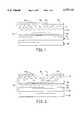
- FIG. 1is a side-elevational view of a composite floor covering of this invention illustrating the various layers thereof, and in which the base fabric is embedded within the plastic matrix of the decorative layer;
- FIG. 2is a side-elevational view similar to FIG. 1 of an alternate embodiment of the present invention in which the fabric base is adhered beneath the plastic matrix of the decorative layer;
- FIGS. 3A through 3Dare plan views of the composite floor covering in accordance with either embodiment of the present invention in which, the fibrous structures comprises individual fibers (FIG. 3A), fabric fragments (FIG. 3B), a combination of individual fibers and fabric fragments (FIG. 3C), and in which the upper surface (facing) of the fabric base has a decorative fabric (FIG. 3D).
- the fibrous structurescomprises individual fibers (FIG. 3A), fabric fragments (FIG. 3B), a combination of individual fibers and fabric fragments (FIG. 3C), and in which the upper surface (facing) of the fabric base has a decorative fabric (FIG. 3D).
- each embodiment of the composite floor covering 10, 10'includes a decorative layer 12, at least one stabilizing layer 24 (of various forms, as will be described), and an optional cushioning layer 28.
- the decorative layer 12itself comprises a fabric base 14 and a plastic matrix 16.
- the upper portion 16T of the plastic matrix 16is transparent.
- the plastic matrix 16may include an optional opaque portion 16D disposed beneath the transparent upper portion 16T.
- At least the transparent portion 16T of the plastic matrix 16has discrete fibrous structures generally indicated by the reference character 18 embedded therein. The decorative effect imparted by the fibrous structures 18, whether taken alone or in combination with the fabric base 14, will be discussed in connection with FIGS. 3A through 3D.
- the fabric base 14is selected from the group consisting of velours, felts, woven, non-woven, knitted, flocked, needle-punched, tufted, and fusion-bonded fabrics, each of which is well known in the art.
- fabricas used herein it is meant a planar textile structure composed of yarns, fibers, or filaments and having an upper surface (facing) and lower surface.
- the fabricsare composed of natural or synthetic fibers.
- Such fibersinclude, for example, wool, cotton, polyamides (such as nylon 6,6, nylon 6, and copolymers thereof), polyesters, polyolefins (such as polypropylene), acrylics, rayon, silk and blends thereof.
- the fabricsmay be textured or non-textured.
- woven fabricsrefer to fabrics formed by weaving (i. e., interlacing) two sets of yarns, known as warp and fill.
- the three basic weavesare plain, twill, and satin.
- yarns running in one direction (fill)go under and over alternate single yarns running in the other direction (warp).
- Plain weave fabricsare strong and durable.
- yarns running in the filling directiongo over one or more warp yarns and under groups of other yarns. Twill weave fabrics are strong with good shape-holding ability.
- the satin weavethe face of the fabric consists almost entirely of warp or filling floats produced in the repeat of a weave. The points of yarn intersection are distributed as evenly and widely separated as possible. Satin-weave fabrics have a smooth, lustrous appearance.
- non-woven fabricsrefer to an assembly of textile fibers held together by interlocking in a random web or mat, by fusing of the fibers, or by bonding with an adhesive.
- Spun-bonded fabricssuch as those sold under the registered trademarks Tyvek® or Typar®, are composed of randomly arranged, continuous filament fibers bonded at filament cross-over points. These fabrics are lightweight and have good tensile and tear strengths.
- Spun-laced fabricssuch as that manufactured and sold by E. I. DuPont de Nemours and Company under the registered trademark Sontara®, are composed of fibers entangled in a predetermined repeating pattern to form a strong, non-bonded structure.
- Knitted fabricsgenerally refer to fabrics which are constructed by interlocking a series of loops of one or more yarns. In warp knitting the yarns generally run lengthwise in the fabric. In weft knitting one continuous thread runs crosswise in the fabric making all of the loops in one course. Weft knitting includes circular knitting and flat knitting. In circular knitting the fabric is produced on the knitting machine in the form of a tube, wherein the threads run continuously around the fabric. In flat knitting the fabric is produced on the knitting machine in flat form, wherein the threads alternate back and forth across the fabric.
- the upper surface (facing) of the fabric base 14may be plain or may carry a decorative design.
- colors and designscan be applied to the fabrics by conventional techniques such as by dyeing the yarns, fibers or filaments which compose the fabric or by dyeing or printing the fabric itself.
- pigmentsare added to the fiber-spinnable polymer melt or solution prior to extrusion of the melt or solution through a spinneret to form solution-dyed fibers.
- the fibersmay be pre-dyed by such techniques as "stock-dyeing" (the dyeing of fibers in staple form).
- the yarnmay be pre-dyed before it used to form a fabric.
- Yarn dyeing techniquesinclude skein-dyeing, space-dyeing and package-dyeing. Dyed yarns of different colors may be used to give the fabric multicolored patterns.
- a second method for imparting a decorative design to fabricsis printing.
- printinginvolves applying coloring agents onto the fabric which is then treated with heat or chemicals to fix the coloring agents.
- Printing techniquesinclude, for example, pigment printing, roller printing, screen printing, and heat transfer printing.
- the plastic matrix 16is formed by a plastisol that comprises, at a minimum, a base resin, a plasticizer, and a stabilizer system.
- the ingredientsare selected such that at least the upper portion 16T of the finished plastic matrix 16 is sufficiently transparent (i. e., clear) that the fibrous structures may be seen therethrough.
- the base resinis typically poly(vinyl chloride).
- Suitable for use as the plasticizeris a polyester plasticizer sold by Huls America, Inc., as NUOPLAS 6000.
- the stabilizer systemmay include a primary stabilizer, such as a mixture of metallo-organic salts. Suitable for use is a mixture of organic salts and barium and zinc, such as that sold by Witco Corporation as Mark 4737.
- the stabilizer systemmay also include a secondary stabilizer, such as epoxidized soybean oil.
- the plastic matrix materialis selected with predetermined melting and rheological characteristics such that the plastic matrix is prepared and applied to the fabric base as a liquid when at room temperature.
- the plastic matrixis such that during the thermal and shear history experienced during the incorporation of the embedded fibrous structures, and the application of the plastic matrix to the fabric base, the fabric base and embedded discrete fibrous structures remain substantially intact.
- the term "intact”means that the fibrous structures are not melted, burned, or otherwise removed during the solidification of the plastic matrix while fabricating the floor covering 10, 10'.
- any transparent polymer that can be processed below the melting point of the fibrous structures 18can be used as the plastic matrix 16.
- Any transparent polymerssuch as the polymers selected from the group consisting of PVC plastisol, PVC/Elvaloy® polymers, urethanes, poly(vinyl chlorides), silicones, fluoropolymers or ionomers like that sold under the registered trademark Surlyn® may be used for the transparent portion of the plastic matrix 16.
- a polymer that flows like a liquid at room temperature so it may be easily applied to the fabric baseis preferred. Some of the polymers listed may have to be heated to become sufficiently fluid to apply to the fabric base. It should also be noted that when certain materials selected for the fabric base, care would have to be exercised to insure that the solidification temperature of the polymer selected for the plastic matrix is less than the melting temperature of the fabric base.
- the plastic matrix 16may also include an opaque portion 16D lying below the transparent portion 16T in which fibrous structures are disposed. If a fabric base having a decorative facing is used, the opaque portion 16D, if one is provided, is always positioned below the fabric base.
- Polymers suitable for use as the opaque portion of the plastic matrixinclude plasticized PVC, PVC/Elvaloy® polymers, ethylene/vinyl acetate copolymer, flexible polyolefin compounds derived from ethylene/propoylene homopolymers and copolymers.
- the fibrous structures 18 disposed within the plastic matrix 16 of the decorative layer 12may themselves take a variety of forms.
- the fibrous structures 18comprises fabric fragments.
- the fabric fragmentshave no dimension greater than about one-and-one-half (1.5) inch.
- the fabric fragmentsare selected from the group consisting of velours, felts, woven, non-woven, knitted, flocked, needle-punched, tufted and fusion-bonded fabrics.
- the fibrous structures 18comprises groupings of multi-oriented individual fibers.
- the fibersare illustrated in the drawings as filamentary members, while the fragments are illustrated an irregularly shaped members generally having a length and a width dimension.
- the length of the individual fibersis greater than about nine (9) millimeters.
- the individual fibersmay be crimped and crinkled.
- the individual fibersare selected from the group consisting of polyester, polypropylene, cotton, silk, wool, acrylic and nylon. A convenient source for such individual fibers is recycled carpet or other textile materials.
- the loading of the fibrous structures (whether implemented as fabric fragments, individual fibers, or a mixture thereof) within the plastic matrix 16 (i. e., in at least the transparent portion 16T thereof)is dependent upon the presence of the decorative design on the facing of the fabric base 14. If the fabric base is plain (i. e., without a decorative design on the facing of the fabric base 14) the fibrous structures may occupy up to about eighty-five percent (85%) of the surface area of the transparent portion 16T of the decorative layer. However, if the facing of the fabric base does carry a decorative design, the fibrous structures may occupy from about five percent (5%) to about fifty percent (50%) of the surface area of the transparent portion 16T of the decorative layer.
- FIGS. 3A through 3DThe decorative effect imparted to the decorative layer 12 by the presence of the fibrous structures 18 is best illustrated in FIGS. 3A through 3D, to which reference is invited. (The reference numerals and lead lines are omitted for clarity of illustration.)
- the fibrous structures 18(whether implemented as individual fibers or as fabric fragments) are visible through the plastic matrix owing to the transparency of the transparent portion thereof.
- FIG. 3Aillustrates the effect with the fibrous structures 18 implemented as individual fibers viewed against a plain fabric base 14.
- FIG. 3Billustrates the effect with the fibrous structures 18 implemented as fabric fragments viewed against a plain fabric base 14.
- FIG. 3CThe effect imparted by a combination of individual fibers and fabric fragments, again viewed against a plain base, is shown in FIG. 3C. From FIGS.
- the fabric base 14whether it is totally or partially embedded within the matrix 16, is visible and serves as a backdrop against which the fibrous structures 18 may be viewed.
- the decorative effectis still further enhanced if the fabric base 14 is itself carries a decorative design.
- FIG. 3Dthe situation in which the fibrous structures are implemented as a combination of individual fibers and fabric fragments is illustrated. It should be apparent that the implementation in which the fibrous structures are all fibers or all fragments (as in FIGS. 3A and 3B, respectively) may be used in the situation of FIG. 3D (in which the fabric base carries a decorative design on the facing thereof), if desired.
- the fibrous structures 18are incorporated into the plastic matrix 16 in a manner such that they remain substantially intact.
- the term “intact”means that the fibrous structures are not melted, burned, or otherwise removed during the solidification of the plastic matrix.
- At least one stabilizing layer 24is disposed beneath the decorative layer 12.
- the stabilizing layerprovides dimensional stability for the composite floor covering 10, 10'.
- the stabilizing layer 24has an upper and lower surface. The upper surface is attached to the lower surface of the decorative layer 12, while the lower surface is in contact and preferably attached to the cushioning layer 28, as described further below. It is important that the floor covering 10, 10' have at least one stabilizing layer, and in some instances where additional stability is required, there should be multiple stabilizing layers. The stabilizing layer also promotes better adhesion between the decorative layer 12 and the cushioning layer 28. The stabilizing layer 24 also provides resistance against punctures to the decorative layer and cushioning layer and tends to reduce the degree of indentation marks when furniture legs and the like are placed on the floor covering. Finally, the stabilizing layer can also provide resistance against wear when the floor covering is subjected to heavy foot traffic.
- the stabilizing layer 24is implemented as a separate layer attached beneath the decorative layer 12.
- the stabilizing layer 24may be attached to the decorative layer 12 using a suitable adhesive 26 which may be permanent or releasable.
- suitable adhesivesinclude the following.
- Suitable aqueous latex adhesivesinclude, for example, styrene-butadiene copolymers, ethylene/vinyl acetate copolymers, polyacrylates and blends thereof. Non-aqueous latex adhesives may also be used.
- thermoplastic adhesivesinclude, for example, polyvinyl chlorides, polyurethanes, polyolefins, ethylene/vinyl ester copolymers, ethylene/alkyl (meth) acrylate copolymers, and ethylene/olefin copolymers.
- Suitable hot-melt adhesivesinclude, for example, adhesives comprising a thermoplastic resin, tackifying resins, waxes, and plasticizers.
- the thermoplastic and hot-melt adhesives in the form of filmsmay be used.
- the stabilizing layermay be coated with the adhesive in any manner such as by spraying, dipping, kiss-roll coating, or by lamination.
- the stabilizing layermay be attached to the underside of the decorative fabric by a pressure sensitive adhesive, mechanical means such as by a Velcro® hook and loop fastening system or by ultrasonic bonding.
- the adhesive properties of the plastic matrix 16 itselfmay be used to adhere the stabilizing layer to the decorative layer.
- the material of the stabilizing layermay be adhered to the lower surface of the opaque portion 16D (if provided) of the plastic matrix 16. If no opaque portion 16D is provided, the stabilizing layer may be adhered to the lower surface of the transparent portion 16T of the plastic matrix 16. No separate adhesive layer is required in such a case.
- the stabilizing layer 24is attached beneath the fabric base 14 using the adhesive 26.
- the fabric base 14is selected from a material that has sufficient elongation, strength, dimensional stability and puncture resistance so as to function as a stabilizing layer.
- the stabilizing layeris typically a scrim or sheet material comprising a fibrous non-woven material or thermoplastic compound.
- the scrimmay comprise an open network of intersecting strands such as, for example, fiberglass, polyolefin, polyamide, cotton, jute, acrylic and polyester strands. Fiberglass strands are particularly effective, because of their good tensile strength and "moisture stability.” By the term, “moisture stability”, it is meant that the length of the strands are substantially unchanged due changes in the temperature and humidity.
- the thickness of the scrimshould generally be in the range of about three (3) to about two-hundred-fifty (250) mils.
- the amount of strands running in the "machine direction”(length direction), i. e., the direction in which the scrim is being produced by the machine and the amount of strands running in the "cross direction” (width direction), i. e., the direction perpendicular to the direction in which the scrim is being produced by the machine are equal.
- the strandsshould also be equally spaced apart in the length direction and width direction.
- Fibrous non-woven sheetsare described above and include spun-bonded fabrics such as those sold under the registered trademarks Tyvek®, Typar®, and Reemay® and spun-laced fabrics such as that sold under the registered trademark Sontara®.
- Thermoplastic compoundscan also be used to make sheet materials having good stabilizing properties.
- a scrim of glass coated polyester strandsis particularly suitable.
- the stabilizing layermay comprise a non-woven sheet adhered to a scrim.
- a brushed knitted fabric having loopy surfacecan also be used as a stabilizing layer. It is also recognized that these materials may be used in combination with each other.
- the type of material used for the stabilizing layerwill vary depending on the desired properties of the composite floor covering. For instance, certain materials may be more effective in providing resistance against indentation marks from heavy furniture and appliances. Other materials may be more effective in providing puncture resistance or may provide better fabrication.
- the composite floor coveringmay further include a cushioning 28 provided, as an option, for cushioning and support.
- the cushioning layer 28is disposed beneath the stabilizing layer 24 (if provided). If a stabilizing layer is not provided, as in the instance in which the fabric base 14 functions as a stabilizing layer, the cushioning layer 28 is attached to the undersurface of the fabric base 14.
- the cushioning layer 28comprises fiber felts or a foamed composition selected from the group consisting of rubber, latex, urethane, and poly(vinyl chloride).
- the lower surface of the stabilizing layeris attached to the cushioning layer by such permanent or releasable adhesive means as described above, but this is not necessary. In some instances, it may be desirable to have the stabilizing layer simply lay on the cushioning layer. As will be discussed herein, the alternate embodiment of the invention comprehends this possibility.
- the cushioning layermay comprise any suitable material such as for example, foamed compositions of rubber, latex, hot-melt resins, urethane, poly(vinyl chloride) resins. These compositions may be combined with fabrics such as velours, felts, wovens, non-wovens, knitted, flocked, needle-punched, and fusion-bonded to provide a good cushioning layer. Fibers used for the cushioning layer are polyamide, polyester, polyolefin, jute, acrylic or cotton. Carpets such as unitary carpets and particularly tufted carpets having a tufted primary backing laminated to a secondary backing may also be used.
- foamed compositions of rubber, latex, hot-melt resins, urethane, poly(vinyl chloride) resinsmay be combined with fabrics such as velours, felts, wovens, non-wovens, knitted, flocked, needle-punched, and fusion-bonded to provide a good cushioning layer.
- the thickness of the cushioning layeris at least one-tenth (0.1) inches and is preferably in the range of about 0.125 inches to about 0.625 inches.
- the density of the cushioning layeris greater than three (3) lbs/ft 3 .
- the thickness and density of the cushioning layerare significant, because these properties help provide the desired resilience and cushioning effect to the entire floor covering.
- the secondary backingbe attached to the lower surface of the stabilizing layer and that the projecting tufts be in contact with the floor.
- a transparent flexible wear layer 32may be disposed over the plastic matrix of the decorative layer.
- the transparent wear layermay be implemented using urethane, poly(vinyl chloride), silicone or fluoropolymer.
- the fibrous structures 18may be incorporated into the plastic matrix 16 by a number of different methods. In one instance the fibrous structures 18 are mixed into the liquid plastisol. This mixture is then applied to the fabric base 14. This composite is then placed in an oven and the plastisol is solidified.
- An alternate methodmay be used in which the plastisol containing the fibrous structures is solidified first, and the resulting solid, clear plastic is cut into pieces. These pieces are then distributed randomly over a base opaque PVC layer and supported underneath with a stabilizing fabric base.
- the fabric baseis a decorative fabric
- the plastic matrix containing the fibrous material in the form of pellets or small piecesare distributed directly over the decorative fabric, so that the fabric base design shows through.
- the productis then compressed under conditions in which the plastic matrix will melt, but the fibrous structures will not.
- a third methodincludes feeding the solid plastic matrix material and the fibrous structures into an extruder.
- the extruderis operated at conditions at which the plastic matrix material melts but the fibrous structures do not. In all cases minimal shear is applied to the mixture so that the fibrous structures remain as discrete pieces, visible within the plastic matrix.
- the fabric base 14may be embedded within the plastic matrix 16, as is illustrated for the composite floor covering 10 of FIG. 1. This arrangement is realized by placing the fabric base 14 above and below a suitable layer of plastic matrix material prior to solidification of the plastic matrix.
- the fabric base 14may define the lower surface of the plastic matrix 16. This arrangement may be achieved by layering plastic matrix material over the fabric base 14 prior to solidification of the plastic matrix 16. The adhesive properties of the matrix serves to hold the base 14 in place. Alternatively, the base 14 may be secured to the lower surface of the matrix 16 after is has been formed using a a suitable adhesive 26.
- the product of the present inventionis primarily used for a floorcovering, other uses should be apparent.
- the present inventionmay be used for tile, as a baseboard material, or as countertop material.
- a plastisolis prepared with the following composition:
- nylon 6,6 yarnswith different colors are mixed to distribute the yarns throughout the plastisol composition. Mixing of the plastisol and yarns is done at low shear to minimize damage to the yarns.
- the nylon yarnsconsist of pink eighteen denier per filament (18 dpf) yarns cut to nine (9) mm lengths and seven (7) with range of seventeen to twenty-three denier per filament (17 to 23 dpf) yarns each with different colors--light green, charcoal, pink, tan, blue, purple and white--with cut lengths between nine and twenty-five millimeters (9 and 25 mm.). Total denier of the yarns is between 1100 and 1750.
- the PVC plastisol/yarn mixtureis spread upon a Teflon® film and heated in an oven at 320° F. for five (5) minutes to solidify the plastisol.
- the yarns and separated filamentsare easily seen in the clear, flexible PVC matrix.
- the PVC matrixis stripped from the Teflon® film and cut into pieces approximately twenty-five millimeters square (25 mm ⁇ 25 mm) in size. These pieces are distributed randomly on a solid, opaque, filled poly(vinyl chloride) composition to cover about fifty percent (50%) of the surface area of the decorative layer.
- This decorative layercomprising a plastic matrix having discrete fibrous structures embedded therein was placed over a 3.3 oz./yd 2 , PVC-coated polyester open mesh backing which acts as a fabric base and as a stabilizing layer.
- the composite structurewas then compressed at approximately one thousand pounds per square inch (1000 psi) for five (5) minutes at 350° F. This causes the matrix to fuse together in which the fabric base/stabilizing layer gets embedded into the matrix.
- the fabric base/stabilizing layerremains intact.
- the fibrous structures in the form of yarn and randomly disposed group of its individual filamentsalso stays intact and are easily seen in the clear layer contrasted against the opaque PVC base layer.
- the composite structurewas used as a floorcovering and was placed over a one-quarter inch thick, eighteen pounds per cubic foot density (18 lbs/ft 3 ) rubber cushion.
- Example 1The process of Example 1 is repeated except that the yarns are replaced by five percent (5%) weight of the cut fragments of fabric.
- Approximately half of the fabric fragmentsare four colors of cotton/rayon apparel fabric in which the yarns are approximately seventy (70) denier. The colors are orange, beige, green, and blue.
- the remainder of the fabric fragmentsare green/black, nylon/Lycra® spandex apparel fabrics in which the yarns are approximately seventy (70) denier.
- These cut fragments of fabricare in different shapes and sizes up to maximum of about one-and-one-half (1.5) inch in any direction.
- the resulting fragmentsare mixed with the PVC plastisol of Example 1 and processed as in Example 1.
- the stabilizing layer/fabric basestays substantially intact and the fabric fragments are visible against the opaque PVC layer.
- a bottom cushioning layer of one-quarter inch thick, eighteen pounds per cubic foot density (18 lbs/ft 3 ) rubber cushionwas used to construct a composite floor covering.
- Example 22.5% by weight of the fibrous material are the yarns of Example 1 and 2.5% by weight are the fabric fragments of Example 2 for a total of 5% by weight of fibrous material. These are mixed with the clear PVC plastisol at low shear. The final product has a combination of the features of Examples 1 and 2.
- Example 3a dyed, 10.7 oz/yd 2 , polyester/cotton, woven textured fabric (decorative fabric) was used as a stabilizing layer in place of a PVC-coated polyester backing.
- the PVC plastisol/fibrous structure compound as prepared in Example 3is spread upon a Teflon® film and heated in an oven at 320° F. for five (5) minutes to solidify the plastisol.
- the fibrous structuresare easily seen in the clear, flexible PVC matrix.
- This decorative PVC matrixis stripped from the Teflon® film and cut into pieces approximately ten millimeters square (10 mm ⁇ 10 mm) in size. These pieces are distributed randomly over the decorative, textured fabric base to cover about five percent (5%) of the surface area of the decorative layer.
- the composite structurewas then compressed at approximately one thousand pounds per square inch (1000 psi) for five (5) minutes at 350° F. This causes the matrix to fuse together.
- the composite productis thus formed with a top layer of a decorative plastic matrix layer which contains the fibrous structures supported underneath with a decorative fabric base which stays intact.
- the productdisplays the base fabric design with clear PVC layer on the facing of the fabric in which the discrete fibrous structures are also seen. Since the yarn components of the decorative woven fabric base had the melt temperature higher than 350° F., the final product had an interesting three-dimensional effect with the decorative fabric showing through the discrete fibrous structures.
- the composite structurewas used as a floorcovering and was placed over a one-quarter inch thick, eighteen pounds per cubic foot density (18 lbs/ft 3 ) rubber cushion.
- Example 1Ninety-five percent (95%) by weight of this composition and five percent (5%) by weight of the yarns of Example 1 are mixed and fed to a one-and-one-half inch (1.5 in) single screw extruder with the screen pack and breaker plate removed to minimize shear.
- the cylindrical extrudateis converted to pellets approximately nine to thirteen millimeters (9 to 13 mm) in diameter and approximately nine millimeters (9 mm) in length.
- the pelletsare distributed randomly on the surface of a solid, opaque, filled poly(vinyl chloride) composition to cover about fifty percent (50%) of the surface area.
- This decorative layercomprising a plastic matrix having discrete fibrous structures embedded therein was placed over a 3.3 oz./yd 2 , PVC-coated polyester open mesh backing which acts as a fabric base and as a stabilizing layer.
- the composite structurewas then placed in a press at one thousand pounds per square inch (1000 psi) for five (5) minutes at 350° F. This causes the matrix to fuse together in which the fabric base/stabilizing layer stays intact.
- the fibrous structures which are embedded in the clear plastic matrixare visible against the opaque PVC layer giving the visual appearance similar to the product as described in Example 1.
- the final composite floorcoveringwas prepared with the above-described product having a bottom cushioning layer of a one-quarter inch thick, eighteen pounds per cubic foot density (18 lbs/ft 3 ) rubber cushion.
- Example 5The process of Example 5 is repeated with five (5%) by weight of the cut fabrics of Example 2 replacing the yarns of Example 5.
- the final productresembles the appearance of the Example 2.
- Example 5The process of Example 5 is repeated except that the 2.5% by weight of the fibrous material are the yarns of Example 1 and 2.5% by weight are the fabric fragments of Example 2 for a total of 5% by weight of fibrous material.
- the final productis comparable to the product of Example 3.
- Example 4the decorative woven fabric of Example 4 is used in place of a PVC-coated polyester backing as a stabilizing layer.
- the fibrous materialconsisted of 2.5% by weight of colored yarns as in Example 1 and 2.5% by weight of colored fabric fragments of Example 2.
- a clear plastic matrix containing these fibrous materials in the form of pelletswere prepared as the above Example 5 and sprinkled randomly over the decorative textured fabric base to cover about five percent (5%) of its surface area.
- the composite structurewas then compressed at approximately one thousand pounds per square inch (1000 psi) for five (5) minutes at 350° F.
- the final product characteristicshad similar three-dimensional features as described in Example 4.
- the samplewas prepared as in Example 1, except that the stabilizing layer was a brushed knit nylon fabric weighing about 2.2 oz./yd 2 .
- the lower surface of the stabilizing layerwas in the form of a loop-covered surface.
- the stabilizing fabric basewas not embedded in the plastic matrix as in Example 1, but rather it was underneath the decorative top layer which consisted of clear plastic matrix having fibrous material over an opaque PVC layer.
- the hook portion of a Velcro®-type mechanical fastenerwas adhered to the floor and in the other case on to a one-quarter inch (1/4") thick rubber cushion having a density of eighteen pounds per cubic foot (18 lbs/ft 3 ).
- the floor covering productwas then assembled by simply pressing the loop covered lower surface of the stabilizing layer on to the hook portion of the upper surface of the floor or the cushioning layer.
- the upper decorative top layer with the stabilizing layerwas able to be detached (as for repair, or replacement, etc.) and re-attached for further use.
- the samplewas prepared as in Example 9, except that the top decorative layer had a thin layer of protective polyurethane coating on its surface.
Landscapes
- Laminated Bodies (AREA)
- Floor Finish (AREA)
- Carpets (AREA)
- Synthetic Leather, Interior Materials Or Flexible Sheet Materials (AREA)
Abstract
Description
______________________________________ Parts by Weight ______________________________________ Poly(vinyl chloride) 100 NUOPLAS 6000 (a) 50 Mark 4737 (b) 3 Epoxidized soybean oil 5 ______________________________________ (a) NUOPLAS 6000 is a polyester plasticizer sold by Huls America, Inc. (b) Mark 4737 is a barium and zinc stabilizer sold by Witco Corporation.
______________________________________ Parts by Weight ______________________________________ Poly(vinyl chloride) 100 Ethylene/ester/carbon monoxide terpolymer 100 Mark 4737 (b) 5 Epoxidized soybean oil 8 Di-Lauryl Thiodipropionate 1.5 Irganox 1010 (c) 0.5 Calcium carbonate 5 ______________________________________ (c) Manufactured by CibaGeigy Corporation
Claims (20)
Priority Applications (8)
| Application Number | Priority Date | Filing Date | Title |
|---|---|---|---|
| US08/770,192US5747133A (en) | 1996-12-19 | 1996-12-19 | Decorative composite floor coverings |
| AU58048/98AAU725200B2 (en) | 1996-12-19 | 1997-12-17 | Decorative composite floor coverings |
| CA002268839ACA2268839C (en) | 1996-12-19 | 1997-12-17 | Decorative composite floor coverings |
| EP97954210AEP0946814B1 (en) | 1996-12-19 | 1997-12-17 | Decorative composite floor coverings |
| JP10528027AJP2000505845A (en) | 1996-12-19 | 1997-12-17 | Decorative composite floor covering |
| PCT/US1997/023709WO1998027265A1 (en) | 1996-12-19 | 1997-12-17 | Decorative composite floor coverings |
| BR9714495ABR9714495A (en) | 1996-12-19 | 1997-12-17 | Composite floor covering. |
| DE69719548TDE69719548T2 (en) | 1996-12-19 | 1997-12-17 | DECORATIVE FLOORING |
Applications Claiming Priority (1)
| Application Number | Priority Date | Filing Date | Title |
|---|---|---|---|
| US08/770,192US5747133A (en) | 1996-12-19 | 1996-12-19 | Decorative composite floor coverings |
Publications (1)
| Publication Number | Publication Date |
|---|---|
| US5747133Atrue US5747133A (en) | 1998-05-05 |
Family
ID=25087760
Family Applications (1)
| Application Number | Title | Priority Date | Filing Date |
|---|---|---|---|
| US08/770,192Expired - LifetimeUS5747133A (en) | 1996-12-19 | 1996-12-19 | Decorative composite floor coverings |
Country Status (8)
| Country | Link |
|---|---|
| US (1) | US5747133A (en) |
| EP (1) | EP0946814B1 (en) |
| JP (1) | JP2000505845A (en) |
| AU (1) | AU725200B2 (en) |
| BR (1) | BR9714495A (en) |
| CA (1) | CA2268839C (en) |
| DE (1) | DE69719548T2 (en) |
| WO (1) | WO1998027265A1 (en) |
Cited By (37)
| Publication number | Priority date | Publication date | Assignee | Title |
|---|---|---|---|---|
| US6050040A (en)* | 1997-09-05 | 2000-04-18 | Jones; Craig S. | Decorative anti slip floor covering |
| KR20020067086A (en)* | 2001-02-15 | 2002-08-22 | 주식회사 엘지화학 | Floor Tile Having Carpet Appearance by Using Synthetic Fiber and the Method of Manufacturing thereof |
| US6444075B1 (en) | 1998-11-27 | 2002-09-03 | Armstrong World Industries, Inc. | Hot melt calendered or extruded wear layer for embossed substrates and method of manufacture |
| US20020156634A1 (en)* | 1999-05-04 | 2002-10-24 | Blum Ronald D. | Floor mat with voice-responsive display |
| US20030024637A1 (en)* | 1997-10-06 | 2003-02-06 | Min Ill Hong | Method for forming an abrasion resistant laminate |
| US20030114062A1 (en)* | 2000-06-19 | 2003-06-19 | Graham Scott | Floor covering with woven face |
| EP1362695A1 (en)* | 2002-05-14 | 2003-11-19 | Armstrong World Industries, Inc. | Resilient flooring structure with encapsulated fabric |
| EP1308120A3 (en)* | 1999-05-04 | 2003-12-03 | IntelliMats, LLC | Floor mat |
| US20040001002A1 (en)* | 1999-05-04 | 2004-01-01 | Blum Ronald D. | Floor display system with interactive features |
| US20040021617A1 (en)* | 1999-05-04 | 2004-02-05 | Blum Ronald D. | Modular protective structure for floor display |
| US20040071926A1 (en)* | 2002-10-15 | 2004-04-15 | Dimitri Zafiroglu | Stitched-bonded yarn surface structure |
| US20040106346A1 (en)* | 2002-11-29 | 2004-06-03 | Zafiroglu Dimitri Peter | Textured composite material |
| US20040119602A1 (en)* | 1999-05-04 | 2004-06-24 | Blum Ronald D. | Floor display system with variable image orientation |
| US6873266B2 (en) | 1999-05-04 | 2005-03-29 | Intellimats, Llc | Electronic floor display |
| WO2004109035A3 (en)* | 2003-06-04 | 2005-06-16 | Mohawk Brands Inc | Woven face pvc floor covering |
| US20050134474A1 (en)* | 1999-05-04 | 2005-06-23 | William Kokonaski | Display system for use on horizontal or non-horizontal surfaces |
| US6940418B2 (en) | 1999-05-04 | 2005-09-06 | Intellimats, Llc | Electronic floor display cleaning system and protective cover |
| US20060049955A1 (en)* | 1999-05-04 | 2006-03-09 | Blum Ronald D | Electronic floor display with weight measurement and reflective display |
| US20060092150A1 (en)* | 2003-02-20 | 2006-05-04 | Blum Ronald D | Electronic display device with adjustable incline for floor advertising/messaging |
| US20060183389A1 (en)* | 2003-07-01 | 2006-08-17 | Zafiroglu Dimitri P | Fabric-faced composites and methods for making same |
| US7205903B2 (en) | 1999-05-04 | 2007-04-17 | Intellimat, Inc. | Interactive and dynamic electronic floor advertising/messaging display |
| US7358861B2 (en) | 1999-05-04 | 2008-04-15 | Intellimats | Electronic floor display with alerting |
| US7511630B2 (en) | 1999-05-04 | 2009-03-31 | Intellimat, Inc. | Dynamic electronic display system with brightness control |
| EP1513973A4 (en)* | 2002-06-14 | 2009-09-16 | Milliken & Co | Carpet tile constructions and methods |
| US20090306599A1 (en)* | 2005-11-28 | 2009-12-10 | Japan Science And Technology Agency | Flocked medical instrument to be placed in the body, method of producing the medical instrument to be placed in the body and apparatus for producing the medical instrument to be placed in the body |
| FR2935413A1 (en)* | 2008-08-29 | 2010-03-05 | Gerflor | Floor and wall covering for building, has stabilization layer formed with material elements and integrated with decorative surface layer, where stabilization layer limits dimensional deformations of covering during temperature variations |
| US20130251964A1 (en)* | 2012-03-23 | 2013-09-26 | Chao-Yang Chen | Composite Board |
| WO2014052696A1 (en) | 2012-09-28 | 2014-04-03 | Trinh Dennis Sam | Furniture drawer locking device |
| CN103781629A (en)* | 2011-09-06 | 2014-05-07 | 乐金华奥斯株式会社 | Inlaid type floor sheet having polyvinyl chloride chip and method of manufacturing thereof |
| US10450760B2 (en) | 2006-01-12 | 2019-10-22 | Valinge Innovation Ab | Floorboards comprising a decorative edge part in a resilient surface layer |
| US10486399B2 (en) | 1999-12-14 | 2019-11-26 | Valinge Innovation Ab | Thermoplastic planks and methods for making the same |
| US10738482B2 (en) | 2009-06-12 | 2020-08-11 | I4F Licensing Nv | Floor panel and floor covering consisting of a plurality of such floor panels |
| US10947741B2 (en) | 2017-04-26 | 2021-03-16 | I4F Licensing Nv | Panel and covering |
| US10975580B2 (en) | 2001-07-27 | 2021-04-13 | Valinge Innovation Ab | Floor panel with sealing means |
| US20220048276A1 (en)* | 2019-11-01 | 2022-02-17 | Thorhammer, Llc | Floor And Wall Panel System |
| US11274471B2 (en) | 2018-12-07 | 2022-03-15 | Albert Long Trinh | Furniture drawer securement device |
| US11655638B2 (en) | 2014-07-04 | 2023-05-23 | Flooring Industries Limited, Sarl | Floor panel and method for manufacturing floor panels |
Families Citing this family (3)
| Publication number | Priority date | Publication date | Assignee | Title |
|---|---|---|---|---|
| FR2820364B1 (en)* | 2001-02-06 | 2003-04-18 | Elianne Charles | COMPOSITE BODY WITH DECORATIVE EFFECT |
| RU2533358C1 (en)* | 2013-05-06 | 2014-11-20 | Гудым Светлана Александровна | Method of production of decorative article |
| WO2014182193A1 (en)* | 2013-05-06 | 2014-11-13 | Gudym, Svetlana Aleksandrovna | Method of fabricating decorative products and the multilayered substrate for the implementation of the method |
Citations (22)
| Publication number | Priority date | Publication date | Assignee | Title |
|---|---|---|---|---|
| US2629678A (en)* | 1950-09-11 | 1953-02-24 | Andrews Alderfer Company | Artificial leather |
| US2688578A (en)* | 1951-10-17 | 1954-09-07 | Us Rubber Co | Stretchable floor covering |
| US3002868A (en)* | 1959-03-02 | 1961-10-03 | Boivin Horace | Sponge back floor covering |
| GB1080046A (en)* | 1964-08-05 | 1967-08-23 | Schusterinsel Opladen Textilve | Composite material |
| US3360422A (en)* | 1965-10-19 | 1967-12-26 | Armstrong Cork Co | Reinforced cellular floor covering |
| GB1128801A (en)* | 1964-08-14 | 1968-10-02 | Ici Ltd | Floor coverings |
| US3458337A (en)* | 1966-06-06 | 1969-07-29 | Gaf Corp | Method for making covering materials incorporating foamed resin material and product thereof |
| FR2017915A1 (en)* | 1968-09-12 | 1970-05-22 | Balamundi Nederland Nv | Production of patterned plastics material for use as a - floor covering material |
| GB1194027A (en)* | 1967-08-04 | 1970-06-10 | Monsanto Tectiles Ltd Formerly | Soft Floor Coverings |
| BE762634A (en)* | 1971-02-08 | 1971-07-16 | Fruy Francois | Composite sheet for covering floors wallsand ceiling |
| US3620890A (en)* | 1968-03-04 | 1971-11-16 | New London Mills Inc | Floor and wall covering and method of making same |
| FR2160631A1 (en)* | 1971-11-18 | 1973-06-29 | Levy Albert | Composite fabric - comprising knitted web secured to plastic substrate is used for furnishing |
| US3871948A (en)* | 1971-04-01 | 1975-03-18 | Bigelow Sanford Inc | Non-woven carpet material with resilient backing |
| US4018957A (en)* | 1975-04-01 | 1977-04-19 | Gaf Corporation | Coated fabric sheet-type material having resilient backing and process for making same |
| US4138521A (en)* | 1974-11-14 | 1979-02-06 | Nairn Floors Limited | Flooring materials |
| US4522857A (en)* | 1984-09-24 | 1985-06-11 | Milliken Research Corporation | Carpet tile with stabilizing material embedded in adhesive layer |
| US4844765A (en)* | 1987-10-14 | 1989-07-04 | Amoco Corporation | Method for preparing tufted pile carpet and adhesive therefor |
| US4939036A (en)* | 1987-10-14 | 1990-07-03 | Amoco Corporation | Method for preparing tufted pile carpet and adhesive therefor |
| JPH058360A (en)* | 1991-07-03 | 1993-01-19 | Kawaguchi Gosei Kk | Preparation of sheet |
| JPH0592538A (en)* | 1991-09-30 | 1993-04-16 | Toppan Printing Co Ltd | Decorative sheet and its manufacture |
| JPH05263372A (en)* | 1992-03-12 | 1993-10-12 | Mitsubishi Rayon Co Ltd | Sheet material and manufacturing method thereof |
| GB2284612A (en)* | 1993-12-03 | 1995-06-14 | Amtico Company Limited The | Colourants, coloured articles and methods of making them |
Family Cites Families (7)
| Publication number | Priority date | Publication date | Assignee | Title |
|---|---|---|---|---|
| GB688373A (en)* | 1948-11-10 | 1953-03-04 | Congoleum Nairn Inc | Improvements in laminated floor and wall covering material |
| US3157561A (en)* | 1960-01-25 | 1964-11-17 | Sandura Company | Hard surface floor covering and method of manufacture |
| US4310581A (en)* | 1980-02-04 | 1982-01-12 | Armstrong Cork Company | Surface covering articles |
| GB8531514D0 (en)* | 1985-12-20 | 1986-02-05 | Halstead Ltd James | Surface covering material |
| US5772941A (en)* | 1995-03-16 | 1998-06-30 | Bando Chemical Industries, Ltd. | Polyvinyl chloride resin sheets and production thereof |
| AU6336496A (en)* | 1995-06-26 | 1997-01-30 | E.I. Du Pont De Nemours And Company | Decorative composite floor coverings |
| JPH0952209A (en)* | 1995-08-10 | 1997-02-25 | Toli Corp Ltd | Floor material prepared by laminating surface layer containing short fibers |
- 1996
- 1996-12-19USUS08/770,192patent/US5747133A/ennot_activeExpired - Lifetime
- 1997
- 1997-12-17DEDE69719548Tpatent/DE69719548T2/ennot_activeExpired - Fee Related
- 1997-12-17JPJP10528027Apatent/JP2000505845A/enactivePending
- 1997-12-17EPEP97954210Apatent/EP0946814B1/ennot_activeExpired - Lifetime
- 1997-12-17BRBR9714495Apatent/BR9714495A/ennot_activeApplication Discontinuation
- 1997-12-17WOPCT/US1997/023709patent/WO1998027265A1/enactiveIP Right Grant
- 1997-12-17AUAU58048/98Apatent/AU725200B2/ennot_activeCeased
- 1997-12-17CACA002268839Apatent/CA2268839C/ennot_activeExpired - Fee Related
Patent Citations (22)
| Publication number | Priority date | Publication date | Assignee | Title |
|---|---|---|---|---|
| US2629678A (en)* | 1950-09-11 | 1953-02-24 | Andrews Alderfer Company | Artificial leather |
| US2688578A (en)* | 1951-10-17 | 1954-09-07 | Us Rubber Co | Stretchable floor covering |
| US3002868A (en)* | 1959-03-02 | 1961-10-03 | Boivin Horace | Sponge back floor covering |
| GB1080046A (en)* | 1964-08-05 | 1967-08-23 | Schusterinsel Opladen Textilve | Composite material |
| GB1128801A (en)* | 1964-08-14 | 1968-10-02 | Ici Ltd | Floor coverings |
| US3360422A (en)* | 1965-10-19 | 1967-12-26 | Armstrong Cork Co | Reinforced cellular floor covering |
| US3458337A (en)* | 1966-06-06 | 1969-07-29 | Gaf Corp | Method for making covering materials incorporating foamed resin material and product thereof |
| GB1194027A (en)* | 1967-08-04 | 1970-06-10 | Monsanto Tectiles Ltd Formerly | Soft Floor Coverings |
| US3620890A (en)* | 1968-03-04 | 1971-11-16 | New London Mills Inc | Floor and wall covering and method of making same |
| FR2017915A1 (en)* | 1968-09-12 | 1970-05-22 | Balamundi Nederland Nv | Production of patterned plastics material for use as a - floor covering material |
| BE762634A (en)* | 1971-02-08 | 1971-07-16 | Fruy Francois | Composite sheet for covering floors wallsand ceiling |
| US3871948A (en)* | 1971-04-01 | 1975-03-18 | Bigelow Sanford Inc | Non-woven carpet material with resilient backing |
| FR2160631A1 (en)* | 1971-11-18 | 1973-06-29 | Levy Albert | Composite fabric - comprising knitted web secured to plastic substrate is used for furnishing |
| US4138521A (en)* | 1974-11-14 | 1979-02-06 | Nairn Floors Limited | Flooring materials |
| US4018957A (en)* | 1975-04-01 | 1977-04-19 | Gaf Corporation | Coated fabric sheet-type material having resilient backing and process for making same |
| US4522857A (en)* | 1984-09-24 | 1985-06-11 | Milliken Research Corporation | Carpet tile with stabilizing material embedded in adhesive layer |
| US4844765A (en)* | 1987-10-14 | 1989-07-04 | Amoco Corporation | Method for preparing tufted pile carpet and adhesive therefor |
| US4939036A (en)* | 1987-10-14 | 1990-07-03 | Amoco Corporation | Method for preparing tufted pile carpet and adhesive therefor |
| JPH058360A (en)* | 1991-07-03 | 1993-01-19 | Kawaguchi Gosei Kk | Preparation of sheet |
| JPH0592538A (en)* | 1991-09-30 | 1993-04-16 | Toppan Printing Co Ltd | Decorative sheet and its manufacture |
| JPH05263372A (en)* | 1992-03-12 | 1993-10-12 | Mitsubishi Rayon Co Ltd | Sheet material and manufacturing method thereof |
| GB2284612A (en)* | 1993-12-03 | 1995-06-14 | Amtico Company Limited The | Colourants, coloured articles and methods of making them |
Cited By (68)
| Publication number | Priority date | Publication date | Assignee | Title |
|---|---|---|---|---|
| US6050040A (en)* | 1997-09-05 | 2000-04-18 | Jones; Craig S. | Decorative anti slip floor covering |
| US20030024637A1 (en)* | 1997-10-06 | 2003-02-06 | Min Ill Hong | Method for forming an abrasion resistant laminate |
| US6649248B1 (en) | 1998-11-27 | 2003-11-18 | Awi Licensing Company | Hot melt calendered or extruded wear layer for embossed substrates and method of manufacture |
| US7378143B2 (en) | 1998-11-27 | 2008-05-27 | Awi Licensing Company | Hot melt calendered or extruded wear layer for embossed substrates |
| US6444075B1 (en) | 1998-11-27 | 2002-09-03 | Armstrong World Industries, Inc. | Hot melt calendered or extruded wear layer for embossed substrates and method of manufacture |
| US20040048044A1 (en)* | 1998-11-27 | 2004-03-11 | Armstrong World Industries, Inc. | Hot melt calendered or extruded wear layer for embossed substrates and method of manufacture |
| US7358861B2 (en) | 1999-05-04 | 2008-04-15 | Intellimats | Electronic floor display with alerting |
| US6982649B2 (en) | 1999-05-04 | 2006-01-03 | Intellimats, Llc | Floor display system with interactive features |
| US7629896B2 (en) | 1999-05-04 | 2009-12-08 | Intellimat, Inc. | Floor display system with interactive features and variable image rotation |
| EP1308120A3 (en)* | 1999-05-04 | 2003-12-03 | IntelliMats, LLC | Floor mat |
| US20040001002A1 (en)* | 1999-05-04 | 2004-01-01 | Blum Ronald D. | Floor display system with interactive features |
| US20040021617A1 (en)* | 1999-05-04 | 2004-02-05 | Blum Ronald D. | Modular protective structure for floor display |
| US7511630B2 (en) | 1999-05-04 | 2009-03-31 | Intellimat, Inc. | Dynamic electronic display system with brightness control |
| US7456755B2 (en) | 1999-05-04 | 2008-11-25 | Intellimat, Inc. | Floor mat and system having electronic display device connectable to a network |
| US20020156634A1 (en)* | 1999-05-04 | 2002-10-24 | Blum Ronald D. | Floor mat with voice-responsive display |
| US7205903B2 (en) | 1999-05-04 | 2007-04-17 | Intellimat, Inc. | Interactive and dynamic electronic floor advertising/messaging display |
| US20040119602A1 (en)* | 1999-05-04 | 2004-06-24 | Blum Ronald D. | Floor display system with variable image orientation |
| US7145469B2 (en) | 1999-05-04 | 2006-12-05 | Intellimats, Llc | Display system for use on horizontal or non-horizontal surfaces |
| US6873266B2 (en) | 1999-05-04 | 2005-03-29 | Intellimats, Llc | Electronic floor display |
| US7109881B2 (en) | 1999-05-04 | 2006-09-19 | Intellimats Llc | Electronic floor display with weight measurement and reflective display |
| US20060152483A1 (en)* | 1999-05-04 | 2006-07-13 | Blum Ronald D | Floor covering with voice-responsive display |
| US20050134474A1 (en)* | 1999-05-04 | 2005-06-23 | William Kokonaski | Display system for use on horizontal or non-horizontal surfaces |
| US6917301B2 (en) | 1999-05-04 | 2005-07-12 | Intellimats, Llc | Floor display system with variable image orientation |
| US6940418B2 (en) | 1999-05-04 | 2005-09-06 | Intellimats, Llc | Electronic floor display cleaning system and protective cover |
| US20060049955A1 (en)* | 1999-05-04 | 2006-03-09 | Blum Ronald D | Electronic floor display with weight measurement and reflective display |
| US7009523B2 (en) | 1999-05-04 | 2006-03-07 | Intellimats, Llc | Modular protective structure for floor display |
| US10486399B2 (en) | 1999-12-14 | 2019-11-26 | Valinge Innovation Ab | Thermoplastic planks and methods for making the same |
| US20030114062A1 (en)* | 2000-06-19 | 2003-06-19 | Graham Scott | Floor covering with woven face |
| KR20020067086A (en)* | 2001-02-15 | 2002-08-22 | 주식회사 엘지화학 | Floor Tile Having Carpet Appearance by Using Synthetic Fiber and the Method of Manufacturing thereof |
| US10975580B2 (en) | 2001-07-27 | 2021-04-13 | Valinge Innovation Ab | Floor panel with sealing means |
| US20030215618A1 (en)* | 2002-05-14 | 2003-11-20 | Hynicka Steven F. | Resilient flooring structure with encapsulated fabric |
| US20050090167A1 (en)* | 2002-05-14 | 2005-04-28 | Hynicka Steven F. | Resilient flooring structure with encapsulated fabric |
| US6818282B2 (en) | 2002-05-14 | 2004-11-16 | Awi Licensing Company | Resilient flooring structure with encapsulated fabric |
| EP1362695A1 (en)* | 2002-05-14 | 2003-11-19 | Armstrong World Industries, Inc. | Resilient flooring structure with encapsulated fabric |
| EP1513973A4 (en)* | 2002-06-14 | 2009-09-16 | Milliken & Co | Carpet tile constructions and methods |
| US6967052B2 (en) | 2002-10-15 | 2005-11-22 | Invista North America S.A.R.L. | Stitched-bonded yarn surface structure |
| US20040071926A1 (en)* | 2002-10-15 | 2004-04-15 | Dimitri Zafiroglu | Stitched-bonded yarn surface structure |
| US7431975B2 (en) | 2002-11-29 | 2008-10-07 | Dzs, L.L.C. | Textured composite material |
| US20040106346A1 (en)* | 2002-11-29 | 2004-06-03 | Zafiroglu Dimitri Peter | Textured composite material |
| US20040106345A1 (en)* | 2002-11-29 | 2004-06-03 | Zafiroglu Dimitri Peter | Textured composite material |
| US7425359B2 (en) | 2002-11-29 | 2008-09-16 | Dzs, Llc | Textured composite material |
| US20060092150A1 (en)* | 2003-02-20 | 2006-05-04 | Blum Ronald D | Electronic display device with adjustable incline for floor advertising/messaging |
| CN100371161C (en)* | 2003-06-04 | 2008-02-27 | 莫霍克布兰德兹有限公司 | Woven face pvc floor covering |
| WO2004109035A3 (en)* | 2003-06-04 | 2005-06-16 | Mohawk Brands Inc | Woven face pvc floor covering |
| US7622408B2 (en) | 2003-07-01 | 2009-11-24 | Dzs, Llc | Fabric-faced composites and methods for making same |
| US20060183389A1 (en)* | 2003-07-01 | 2006-08-17 | Zafiroglu Dimitri P | Fabric-faced composites and methods for making same |
| US20090306599A1 (en)* | 2005-11-28 | 2009-12-10 | Japan Science And Technology Agency | Flocked medical instrument to be placed in the body, method of producing the medical instrument to be placed in the body and apparatus for producing the medical instrument to be placed in the body |
| US8360000B2 (en) | 2005-11-28 | 2013-01-29 | Japan Science And Technology Agency | Flocked medical instrument to be placed in the body, method of producing the medical instrument to be placed in the body and apparatus for producing the medical instrument to be placed in the body |
| US11702847B2 (en) | 2006-01-12 | 2023-07-18 | Valinge Innovation Ab | Floorboards comprising a decorative edge part in a resilient surface layer |
| US11066836B2 (en) | 2006-01-12 | 2021-07-20 | Valinge Innovation Ab | Floorboards comprising a decorative edge part in a resilient surface layer |
| US10450760B2 (en) | 2006-01-12 | 2019-10-22 | Valinge Innovation Ab | Floorboards comprising a decorative edge part in a resilient surface layer |
| FR2935413A1 (en)* | 2008-08-29 | 2010-03-05 | Gerflor | Floor and wall covering for building, has stabilization layer formed with material elements and integrated with decorative surface layer, where stabilization layer limits dimensional deformations of covering during temperature variations |
| US10738480B2 (en) | 2009-06-12 | 2020-08-11 | I4F Licensing Nv | Floor panel and floor covering consisting of a plurality of such floor panels |
| US11668100B2 (en) | 2009-06-12 | 2023-06-06 | I4F Licensing Nv | Floor panel and floor covering consisting of a plurality of such floor panels |
| US10738481B2 (en) | 2009-06-12 | 2020-08-11 | I4F Licensing Nv | Floor panel and floor covering consisting of a plurality of such floor panels |
| US10738482B2 (en) | 2009-06-12 | 2020-08-11 | I4F Licensing Nv | Floor panel and floor covering consisting of a plurality of such floor panels |
| US20140213132A1 (en)* | 2011-09-06 | 2014-07-31 | Lg Hausys, Ltd. | Inlaid type floor sheet having polyvinyl chloride chip and the method of manufacturing thereof |
| CN103781629A (en)* | 2011-09-06 | 2014-05-07 | 乐金华奥斯株式会社 | Inlaid type floor sheet having polyvinyl chloride chip and method of manufacturing thereof |
| US20130251964A1 (en)* | 2012-03-23 | 2013-09-26 | Chao-Yang Chen | Composite Board |
| WO2014052696A1 (en) | 2012-09-28 | 2014-04-03 | Trinh Dennis Sam | Furniture drawer locking device |
| US12234655B2 (en) | 2014-07-04 | 2025-02-25 | Unilin Bv | Floor panel and method for manufacturing floor panels |
| US11976474B2 (en) | 2014-07-04 | 2024-05-07 | Unilin Bv | Floor panel and method for manufacturing floor panels |
| US11655638B2 (en) | 2014-07-04 | 2023-05-23 | Flooring Industries Limited, Sarl | Floor panel and method for manufacturing floor panels |
| US10947741B2 (en) | 2017-04-26 | 2021-03-16 | I4F Licensing Nv | Panel and covering |
| US11441319B2 (en) | 2017-04-26 | 2022-09-13 | I4F Licensing Nv | Panel and covering |
| US11274471B2 (en) | 2018-12-07 | 2022-03-15 | Albert Long Trinh | Furniture drawer securement device |
| US20220048276A1 (en)* | 2019-11-01 | 2022-02-17 | Thorhammer, Llc | Floor And Wall Panel System |
| US12269251B2 (en)* | 2019-11-01 | 2025-04-08 | Thorhammer, LLC. | Floor and wall panel system |
Also Published As
| Publication number | Publication date |
|---|---|
| DE69719548D1 (en) | 2003-04-10 |
| EP0946814A1 (en) | 1999-10-06 |
| BR9714495A (en) | 2000-03-21 |
| CA2268839A1 (en) | 1998-06-25 |
| AU725200B2 (en) | 2000-10-05 |
| AU5804898A (en) | 1998-07-15 |
| CA2268839C (en) | 2002-11-19 |
| EP0946814B1 (en) | 2003-03-05 |
| JP2000505845A (en) | 2000-05-16 |
| DE69719548T2 (en) | 2003-11-20 |
| WO1998027265A1 (en) | 1998-06-25 |
Similar Documents
| Publication | Publication Date | Title |
|---|---|---|
| US5747133A (en) | Decorative composite floor coverings | |
| CA2315511C (en) | Carpet backing that provides dimensional stability | |
| US5965232A (en) | Decorative composite floor coverings | |
| EP1023485B1 (en) | Floor covering with woven face | |
| US6479125B1 (en) | Backing for tufted carpet that imparts dimensional stability | |
| EP1453666B1 (en) | Tufted covering for floors and/or walls | |
| JP2656372B2 (en) | Rental mats that prevent waves | |
| US20020039636A1 (en) | Carpet and carpet making methods | |
| US20040170799A1 (en) | Heat-insulating material and method of making the same | |
| JP3011602B2 (en) | Dust control mat with excellent dimensional stability and method of manufacturing the same | |
| US20020132084A1 (en) | Carpet and carpet making methods | |
| US7122089B2 (en) | Method of making a textile laminate having pile-like surface | |
| US5494724A (en) | Washable, water and dirt binding service mat | |
| WO1997001665A1 (en) | Decorative composite floor coverings | |
| JP3645609B2 (en) | Pile-shaped rug and method for manufacturing the same | |
| CA2122033A1 (en) | Method for producing tufted and bonded carpet material and the carpet so produced | |
| JP2008188202A (en) | Waterproof and breathable carpet | |
| JPH11350330A (en) | Pile rug | |
| KR100354372B1 (en) | Dust-removing mat with excellent dimensional stability and manufacturing method of the same | |
| JP2656372C (en) | ||
| JPH07279384A (en) | Tile carpet and manufacture thereof | |
| JPS6313742A (en) | Mat for dust removing with label and manufacture thereof | |
| JPH06113944A (en) | Floor member and manufacture thereof |
Legal Events
| Date | Code | Title | Description |
|---|---|---|---|
| AS | Assignment | Owner name:E.I. DU PONT DE NEMOURS AND COMPANY, DELAWARE Free format text:ASSIGNMENT OF ASSIGNORS INTEREST;ASSIGNORS:VINOD, YASHAVANT VINAYAK;WHELCHEL, WAYNE CURTIS;REEL/FRAME:008414/0369 Effective date:19961219 | |
| STCF | Information on status: patent grant | Free format text:PATENTED CASE | |
| FPAY | Fee payment | Year of fee payment:4 | |
| AS | Assignment | Owner name:INVISTA NORTH AMERICA S.A.R.L., DELAWARE Free format text:ASSIGNMENT OF ASSIGNORS INTEREST;ASSIGNOR:E. I. DU PONT DE NEMOURS AND COMPANY;REEL/FRAME:015286/0708 Effective date:20040430 | |
| AS | Assignment | Owner name:JPMORGAN CHASE BANK, N.A., TEXAS Free format text:SECURITY INTEREST;ASSIGNOR:INVISTA NORTH AMERICA S.A.R.L. F/K/A ARTEVA NORTH AMERICA S.A.R.;REEL/FRAME:015592/0824 Effective date:20040430 | |
| FPAY | Fee payment | Year of fee payment:8 | |
| AS | Assignment | Owner name:DEUTSCHE BANK AG NEW YORK BRANCH, AS COLLATERAL AG Free format text:SECURITY AGREEMENT;ASSIGNOR:INVISTA NORTH AMERICA S.A.R.L.;REEL/FRAME:022416/0849 Effective date:20090206 Owner name:INVISTA NORTH AMERICA S.A.R.L. (F/K/A ARTEVA NORTH Free format text:RELEASE OF U.S. PATENT SECURITY INTEREST;ASSIGNOR:JPMORGAN CHASE BANK, N.A., AS ADMINISTRATIVE AGENT AND COLLATERAL AGENT (F/K/A JPMORGAN CHASE BANK);REEL/FRAME:022427/0001 Effective date:20090206 | |
| FPAY | Fee payment | Year of fee payment:12 | |
| AS | Assignment | Owner name:INVISTA NORTH AMERICA S.A.R.L., NORTH CAROLINA Free format text:RELEASE BY SECURED PARTY;ASSIGNOR:DEUTSCHE BANK AG NEW YORK BRANCH;REEL/FRAME:027211/0298 Effective date:20111110 |