US5747103A - Method and apparatus for printign lithium patterns on a press - Google Patents
Method and apparatus for printign lithium patterns on a pressDownload PDFInfo
- Publication number
- US5747103A US5747103AUS08/835,666US83566697AUS5747103AUS 5747103 AUS5747103 AUS 5747103AUS 83566697 AUS83566697 AUS 83566697AUS 5747103 AUS5747103 AUS 5747103A
- Authority
- US
- United States
- Prior art keywords
- lithium
- confinement
- web
- webs
- patterns
- Prior art date
- Legal status (The legal status is an assumption and is not a legal conclusion. Google has not performed a legal analysis and makes no representation as to the accuracy of the status listed.)
- Expired - Fee Related
Links
- 229910052744lithiumInorganic materials0.000titleclaimsabstractdescription111
- WHXSMMKQMYFTQS-UHFFFAOYSA-NLithiumChemical compound[Li]WHXSMMKQMYFTQS-UHFFFAOYSA-N0.000titleclaimsabstractdescription110
- 238000000034methodMethods0.000titleclaimsdescription28
- 238000007639printingMethods0.000claimsabstractdescription32
- 239000007787solidSubstances0.000claimsabstractdescription9
- 239000003792electrolyteSubstances0.000claimsdescription25
- 238000007789sealingMethods0.000claimsdescription16
- 239000004020conductorSubstances0.000claimsdescription12
- 238000010030laminatingMethods0.000claimsdescription12
- 239000003795chemical substances by applicationSubstances0.000claimsdescription10
- 239000007789gasSubstances0.000claimsdescription5
- 239000011261inert gasSubstances0.000claimsdescription4
- 238000010099solid formingMethods0.000claimsdescription4
- 230000001105regulatory effectEffects0.000claimsdescription2
- 238000010438heat treatmentMethods0.000claims5
- 230000001276controlling effectEffects0.000claims1
- 238000007493shaping processMethods0.000claims1
- 230000001681protective effectEffects0.000abstractdescription4
- 239000012080ambient airSubstances0.000abstractdescription3
- WHXSMMKQMYFTQS-BKFZFHPZSA-Nlithium-12Chemical compound[12Li]WHXSMMKQMYFTQS-BKFZFHPZSA-N0.000description15
- 239000000203mixtureSubstances0.000description10
- 239000011888foilSubstances0.000description7
- 239000003570airSubstances0.000description4
- 239000007772electrode materialSubstances0.000description4
- 230000004888barrier functionEffects0.000description3
- 239000011248coating agentSubstances0.000description3
- 238000000576coating methodMethods0.000description3
- 238000010586diagramMethods0.000description3
- 239000002001electrolyte materialSubstances0.000description3
- 238000004519manufacturing processMethods0.000description3
- XKRFYHLGVUSROY-UHFFFAOYSA-NArgonChemical compound[Ar]XKRFYHLGVUSROY-UHFFFAOYSA-N0.000description2
- OKTJSMMVPCPJKN-UHFFFAOYSA-NCarbonChemical compound[C]OKTJSMMVPCPJKN-UHFFFAOYSA-N0.000description2
- 229910052799carbonInorganic materials0.000description2
- 239000000976inkSubstances0.000description2
- 239000000463materialSubstances0.000description2
- 229910052751metalInorganic materials0.000description2
- 239000002184metalSubstances0.000description2
- 108010010803GelatinProteins0.000description1
- 239000011149active materialSubstances0.000description1
- 239000000654additiveSubstances0.000description1
- 230000000996additive effectEffects0.000description1
- 239000000853adhesiveSubstances0.000description1
- 230000001070adhesive effectEffects0.000description1
- 229910052786argonInorganic materials0.000description1
- 239000012300argon atmosphereSubstances0.000description1
- 230000015572biosynthetic processEffects0.000description1
- 230000015556catabolic processEffects0.000description1
- 239000010406cathode materialSubstances0.000description1
- 238000011109contaminationMethods0.000description1
- 238000006731degradation reactionMethods0.000description1
- 230000002708enhancing effectEffects0.000description1
- 229920000159gelatinPolymers0.000description1
- 239000008273gelatinSubstances0.000description1
- 235000019322gelatineNutrition0.000description1
- 235000011852gelatine dessertsNutrition0.000description1
- 238000007646gravure printingMethods0.000description1
- 231100001261hazardousToxicity0.000description1
- 230000003993interactionEffects0.000description1
- 238000003475laminationMethods0.000description1
- 230000000873masking effectEffects0.000description1
- 239000011159matrix materialSubstances0.000description1
- 239000000155meltSubstances0.000description1
- 238000010926purgeMethods0.000description1
- 238000007650screen-printingMethods0.000description1
- 229910000679solderInorganic materials0.000description1
- 229910001220stainless steelInorganic materials0.000description1
- 239000010935stainless steelSubstances0.000description1
- 239000000758substrateSubstances0.000description1
- 238000010023transfer printingMethods0.000description1
Images


Classifications
- H—ELECTRICITY
- H01—ELECTRIC ELEMENTS
- H01M—PROCESSES OR MEANS, e.g. BATTERIES, FOR THE DIRECT CONVERSION OF CHEMICAL ENERGY INTO ELECTRICAL ENERGY
- H01M6/00—Primary cells; Manufacture thereof
- H01M6/40—Printed batteries, e.g. thin film batteries
- H—ELECTRICITY
- H01—ELECTRIC ELEMENTS
- H01M—PROCESSES OR MEANS, e.g. BATTERIES, FOR THE DIRECT CONVERSION OF CHEMICAL ENERGY INTO ELECTRICAL ENERGY
- H01M6/00—Primary cells; Manufacture thereof
- H01M6/14—Cells with non-aqueous electrolyte
- H01M6/16—Cells with non-aqueous electrolyte with organic electrolyte
- Y—GENERAL TAGGING OF NEW TECHNOLOGICAL DEVELOPMENTS; GENERAL TAGGING OF CROSS-SECTIONAL TECHNOLOGIES SPANNING OVER SEVERAL SECTIONS OF THE IPC; TECHNICAL SUBJECTS COVERED BY FORMER USPC CROSS-REFERENCE ART COLLECTIONS [XRACs] AND DIGESTS
- Y10—TECHNICAL SUBJECTS COVERED BY FORMER USPC
- Y10T—TECHNICAL SUBJECTS COVERED BY FORMER US CLASSIFICATION
- Y10T29/00—Metal working
- Y10T29/49—Method of mechanical manufacture
- Y10T29/49002—Electrical device making
- Y10T29/49108—Electric battery cell making
- Y10T29/49115—Electric battery cell making including coating or impregnating
Definitions
- the inventionrelates to the formation of thin layers of lithium in patterns and to printing such lithium patterns on elongated webs, particularly for the purpose of making a succession of thin electrochemical cells on an in-line press.
- Lithiumperforms well as an electrode material in electrochemical cells but, because of its volatility, is difficult and potentially dangerous to handle. In pure form, lithium must be kept in special environments to prevent its interaction with the normal components of air.
- thin electrochemical cellsalso referred to as “laminar”, “flexible”, or “flat” cells, which require only thin layers of active materials, are much more difficult to manufacture with lithium electrodes than with other common electrode materials.
- the heightened performance of lithiumsometimes justifies its increased handling costs.
- the increased costssignificantly limit applications for the thin cells, which are often intended for powering inexpensive products also having a thin form (e.g., smart cards).
- Lithium electrodeshave been made from thin foils that are cut into patterns and laminated together with other thin layers to form individual electrochemical cells. These foils are fragile and are costly to make at reduced thicknesses. Generally, the foils are thicker than necessary for fulfilling their electrochemical functions in cells, which is wasteful and potentially more hazardous. Special equipment must be used for handling the lithium, and a special environment must be maintained throughout the manufacturing process until the lithium foil is sealed within individual cells. The special handling requirements for lithium foils and other difficulties associated with its combination with other layers require time-consuming assembly procedures for the individual cells.
- U.S. Pat. No. 5,350,645 to Lake et al.discloses an alternative method for making a matrix of polymer-lithium cells in sheet form.
- Thin sheets of metal foilsare used as substrates for supporting lithium anodes, which are applied as patterned solder.
- the sheets with presumably differentially treated areasare conveyed across a molten bath of lithium within a protected environment.
- Thin patterns of lithiumare deposited on the sheets, and these sheets are laminated together with other sheets containing electrolyte and cathode materials for completing the cells.
- Molten lithiumrequires more rigorous handling precautions than those for handling lithium in a solid state.
- the protective environment surrounding the molten bathis breached by sheets entering and leaving the environment, which increases risk of contamination or degradation of the environment with potentially disastrous consequences.
- Our inventionprovides for printing a succession of lithium patterns along a web.
- the patternscan be shaped to form electrodes of thin electrochemical cells or other devices.
- manufacturing ratescan be increased to printing speeds while lowering material costs and enhancing safety.
- a first confinementsuch as a tank having a controlled environment (e.g., an argon atmosphere).
- a second confinementsuch as a shroud that has a less rigorously controlled environment.
- Successive portions of the webare maneuvered past a chiller within the shroud.
- the molten lithiumis conveyed from the tank to the shroud and is dispensed through an opening onto the successive portions of the web that are maneuvered past the chiller.
- the dispensed lithiumis chilled to a solid state forming the succession of lithium patterns along the web.
- a sealis applied over the lithium patterns to limit exposure of the lithium patterns to the environment outside the shroud.
- the tank within which the lithium is meltedcan provide a carefully controlled environment that is not breached by web movements.
- the dispensed lithiumcan be nearly instantaneously converted into a solid form and be quickly sealed. Accordingly, only small individual quantities of lithium require protection within the shroud, each for only a small amount of time.
- two websare preferably advanced along an in-line press.
- One of the websis treated as described above for forming a succession of lithium patterns.
- Similar successions of other electrode patterns and electrolyte patternsare printed on either of the webs.
- the two websare sealed together for protecting the lithium patterns and completing a succession of electrochemical cells.
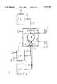
- FIG. 1schematically depicts a station for printing and sealing a succession of lithium patterns on a web.
- FIG. 2diagrams a press incorporating a station similar to the station of FIG. 1 for printing a succession of electrochemical cells.
- FIG. 3displays a broken-away cross-sectional view of the succession of electrochemical cells formed between two webs.
- FIG. 4diagrams an alternative press incorporating a station similar to the station of FIG. 1 for printing a succession of electrochemical cells.
- FIG. 5schematically depicts an alternative station for printing and sealing a succession of lithium patterns on a web.
- FIG. 6diagrams a press incorporating a station similar to the station of FIG. 5 for printing a succession of electrochemical cells.
- FIG. 1A station for printing and sealing lithium patterns along continuous webs is depicted in FIG. 1.
- An enclosed tank 10melts lithium 12 using a heater 14.
- a pump 16evacuates air from the tank 10, which is replaced by an inert gas from a gas supply 18 to provide a controlled non-reactive environment for the molten lithium 12 within the tank 10.
- a conduit 20 interrupted by a control valve 22conveys the molten lithium 12 from the tank 10 to a nozzle 24 having a specially shaped opening 26 within a shroud 30.
- the valve 22can be incorporated into the nozzle 24 for regulating flows of the molten lithium 12 through the opening 26.
- All of the components that come into contact with the molten lithium 12 including portions of the tank 10, the conduit 20, the valve 22, and the nozzle 24are preferably made of stainless steel or other materials that do not react with the molten lithium 12.
- Heaters 28 positioned along the path between the tank 10 and the opening 26maintain the lithium 12 in its molten state until it is discharged from the opening 26.
- a web 32which can be a transverse portion of a wider web or an entire web, advances into the shroud 30 through an entrance 34 and maneuvers past a chiller 36, such as a chilled roller, before leaving the shroud 30 through an exit 38.
- a chiller 36such as a chilled roller
- Another supply 40 of inert gaspurges the shroud 30 of ambient air and maintains a positive pressure within the shroud 30 to keep the air from returning through the entrance 34 or the exit 38.
- the nozzle 24dispenses small quantities of the molten lithium 12 onto successive portions of the web 32 in contact with the chiller 36. Upon contacting the chiller 36, the dispensed quantities of lithium 12 solidify into a succession of individual patterns 42.
- the opening 26 of nozzle 24controls a width of the patterns 42 and the valve 22 controls their length.
- a patterned screen(not shown) could be used to distribute the flow of molten lithium 12 onto the web 32.
- the lithium patterns 42are sealed against exposure to moisture by laminating another web 44 over the web 32. Edges of the laminated webs 32 and 34 can be sealed by heat, adhesives, maskings, or other moisture barriers to further protect the lithium patterns 42.
- the web 44can be a separate web that enters the shroud through its own entrance 46, or the webs 32 and 44 can be different portions of the same web that is slit, shifted and laminated together or is folded and laminated together within the shroud 30 to seal the lithium patterns 42.
- a coating, such as a barrier coating,could also be used to seal the lithium patterns 42.
- the environment within the shroud 30is not controlled to the same extent as the environment within the tank 10, less protection is required for the limited quantities and duration of molten lithium 12 within the shroud 30.
- the solid lithium patterns 42require even less protection.
- the lithium patterns 42preferably emerge from the shroud 30 permanently sealed against exposure to the ambient environment.
- the shroud 30could be replaced or further enhanced by a so-called "gas curtain" that displaces ambient air with a non-reactive gas such as argon in the vicinity of the nozzle 24.
- a dry air environment, such as a dry room,could be provided to permit additional processing steps before finally sealing the lithium patterns 42.
- a station 48 similar to the printing and sealing station of FIG. 1can be incorporated into an in-line press 50 such as depicted in FIG. 2 for making a succession of lithium electrochemical cells such as depicted in FIG. 3.
- the press 50includes separate unwinders 52 and 54 supplying continuous length webs 56 and 58, which are preferably made of moisture-resistant film or similarly impervious paper. Alternatively, moisture barriers could be printed on the webs 56 and 58 along the in-line press.
- Conductor/collector printers 60 and 62separately print conductor/collector patterns 64 and 66 on the two webs 56 and 58 using conductive inks, such as carbon-based inks.
- the printers 60 and 62preferably employ flexographic printing, but other printing techniques could also be employed including screen printing, stencil printing, transfer printing, gravure printing, or other pattern-coating techniques.
- either of the two webs 56 and 58could be made from conductive materials, such as conductive films.
- an electrode printer 68prints an electrode pattern 72 over the conductor/collector pattern 64
- an electrolyte printer 76prints an electrolyte pattern 78 over the electrode pattern 72.
- Both printers 68 and 76can employ any of a variety of printing techniques such as those mentioned for printing the conductor/collector patterns 64 and 66.
- Electrode materials of a more gelatin compositioncan be extruded.
- the electrode and electrolyte materials for forming the electrode and electrolyte patterns 72 and 78must be compatible with lithium electrodes in electrochemical cells.
- a lithium printer 70 of the printing and sealing station 48deposits lithium electrode patterns 74 over the conductor/collector layer 66 within a shroud 80 or other protective confinement such as a gas curtain or dry room. While still within the protective shroud 80, the web 58 advances to a laminator 82 where it is joined with the web 56 to seal the lithium patterns 74 between the two webs 56 and 58.
- the electrolyte patterns 78 of the web 56contact the lithium electrode patterns 74 of the web 58 to form a succession of electrochemical cells 84.
- a graphics printer 86 and a die cutter 88exemplify subsequent operations that can be performed on the laminated webs 56 and 58 to separate the electrochemical cells 84 from each other or to combine the electrochemical cells 84 with other layers or devices.
- a rewinder 90winds the laminated webs 56 and 58 into a roll from which the electrochemical cells 84 can be subsequently dispensed or further processed. Alternatively, the electrochemical cells could be dispensed from the die cutter 88.
- FIG. 4An alternative press 100 for forming similar thin electrochemical cells with lithium electrodes is depicted in FIG. 4.
- a web 102 made up of two adjacent webs 104 and 106advances from an unwinder 108 to a conductor/collector printer 110 that lays down conductive/collector patterns on both webs 104 and 106.
- An electrode printer 112 and an electrolyte printer 114lay down electrode and electrolyte patterns on the web 104.
- Both webs 104 and 106advance together into a shroud 116 or other confinement for a printing and sealing station 98; and a lithium printer 118, similar to the printer depicted in FIG. 1, lays down lithium electrode patterns on the web 106.
- a folder/laminator 120While still within the shroud 116 of the station 98, a folder/laminator 120 folds and laminates the two webs 104 and 106 together to form a succession of electrochemical cells similar to those disclosed in FIG. 3.
- a similar resultcan be attained by separating and shifting the webs 104 and 106 prior to lamination. A variety of subsequent operations can be performed on the web 102, although only a rewinder 122 is actually shown.
- FIG. 5Another station for printing and sealing lithium patterns is depicted in FIG. 5. Components in common with the station of FIG. 1 retain their same reference numerals. Two major differences are evident, either of which could constitute a separate embodiment. One relates to mixing the molten lithium 12 with another agent 132 for forming lithium mixture patterns 142, and another relates to forming electrolyte patterns 152 within the shroud 30 for sealing the lithium mixture patterns 142.
- a tank 130contains the agent 132, which can be carbon or another additive that improves some property of the lithium such as conductivity.
- Conduits 134 and 136convey the molten lithium 12 and the agent 132 from the tanks 10 and 130 to a mixing head 123 of a nozzle 124, where the molten lithium 12 and the agent 132 mix together before being dispensed from the nozzle 124 in the form of the lithium mixture patterns 142.
- Separate valves 144 and 146respective flows from the tanks 10 and 130 to regulate the relative composition of the mixture.
- the electrolyte patterns 152are printed over the lithium mixture patterns 142. Similar to the way in which the molten lithium 12 is dispensed, an electrolyte 148 is drawn from a tank 150, which can be heated, and is conveyed by a conduit 154 through a valve 156 to a nozzle 158. A specially shaped opening 159 in the nozzle 158 together with the valve 156 control the size and shape of the electrode patterns 152. Other forms of printing appropriate for the choice of electrolyte material 148 could also be used for similarly applying the electrolyte patterns 152.
- a press 160 incorporating a printing and sealing station 178 similar to the printing and sealing station of FIG. 5is depicted by FIG. 6.
- Two adjacent webs 162 and 164which are preferably lateral portions of the same web, advance from an unwinder 166 to a conductor/collector printer 168 that prints conductor/collector patterns on at least one of the two webs 162 and 164.
- Electrode printer 170prints electrode patterns in registration with the conductor/collector patterns on the web 162.
- a lithium printer 174prints lithium (or lithium mixture patterns) on the web 164
- an electrolyte printer 176prints electrolyte patterns over the lithium patterns to seal the lithium patterns against exposure to ambient environment.
- the electrolyte printer 176can be arranged to print electrolyte patterns over both the lithium patterns and the electrode patterns to form a succession of electrochemical cells having two electrodes sharing a common layer.
- a laminator 180laps a separate web 182 from another unwinder 184 together with the webs 162 and 164 to provide a more permanent seal for the lithium patterns and additional structure for supporting subsequent operations.
- graphic printer 186is depicted for printing graphical information on the web 182 of a combined web laminate 188 that is subsequently rewound on rewinder 190.
Landscapes
- Engineering & Computer Science (AREA)
- Manufacturing & Machinery (AREA)
- Chemical & Material Sciences (AREA)
- Chemical Kinetics & Catalysis (AREA)
- Electrochemistry (AREA)
- General Chemical & Material Sciences (AREA)
- Battery Electrode And Active Subsutance (AREA)
Abstract
Description
Claims (34)
Priority Applications (4)
| Application Number | Priority Date | Filing Date | Title |
|---|---|---|---|
| US08/835,666US5747103A (en) | 1997-04-10 | 1997-04-10 | Method and apparatus for printign lithium patterns on a press |
| CA002233498ACA2233498A1 (en) | 1997-04-10 | 1998-03-30 | Method and apparatus for printing lithium patterns on a press |
| GB9807472AGB2324066B (en) | 1997-04-10 | 1998-04-07 | Method and apparatus for printing lithium patterns on a press |
| DE19815897ADE19815897A1 (en) | 1997-04-10 | 1998-04-08 | Method and device for printing lithium patterns by a press |
Applications Claiming Priority (1)
| Application Number | Priority Date | Filing Date | Title |
|---|---|---|---|
| US08/835,666US5747103A (en) | 1997-04-10 | 1997-04-10 | Method and apparatus for printign lithium patterns on a press |
Publications (1)
| Publication Number | Publication Date |
|---|---|
| US5747103Atrue US5747103A (en) | 1998-05-05 |
Family
ID=25270140
Family Applications (1)
| Application Number | Title | Priority Date | Filing Date |
|---|---|---|---|
| US08/835,666Expired - Fee RelatedUS5747103A (en) | 1997-04-10 | 1997-04-10 | Method and apparatus for printign lithium patterns on a press |
Country Status (4)
| Country | Link |
|---|---|
| US (1) | US5747103A (en) |
| CA (1) | CA2233498A1 (en) |
| DE (1) | DE19815897A1 (en) |
| GB (1) | GB2324066B (en) |
Cited By (8)
| Publication number | Priority date | Publication date | Assignee | Title |
|---|---|---|---|---|
| US6284405B2 (en)* | 1996-06-19 | 2001-09-04 | Toshiba Battery Co., Ltd. | Nonaqueous electrolyte battery, electrode plate for nonaqueous electrolyte battery, and method for manufacturing electrode plate for nonaqueous electrolyte battery |
| US6761744B1 (en) | 1999-07-16 | 2004-07-13 | Quallion Llc | Lithium thin film lamination technology on electrode to increase battery capacity |
| EP1134831A3 (en)* | 2000-03-17 | 2006-11-22 | Sony Corporation | Method of manufacturing a battery |
| US20080296311A1 (en)* | 2007-06-01 | 2008-12-04 | Illinois Tool Works Inc. | Method and apparatus for dispensing material on a substrate |
| US8445137B1 (en) | 2002-11-27 | 2013-05-21 | Quallion Llc | Primary battery having sloped voltage decay |
| US20130312238A1 (en)* | 2012-05-22 | 2013-11-28 | Jtekt Corporation | Electrode production system |
| US9528033B2 (en) | 2013-11-13 | 2016-12-27 | R.R. Donnelley & Sons Company | Electrolyte material composition and method |
| US10916761B2 (en) | 2016-07-01 | 2021-02-09 | Applied Materials, Inc. | Low melting temperature metal purification and deposition |
Families Citing this family (1)
| Publication number | Priority date | Publication date | Assignee | Title |
|---|---|---|---|---|
| DE102024102608A1 (en)* | 2024-01-30 | 2025-07-31 | Dürr Systems Ag | Plant and method for treating a material to be treated |
Citations (11)
| Publication number | Priority date | Publication date | Assignee | Title |
|---|---|---|---|---|
| US4911995A (en)* | 1987-03-11 | 1990-03-27 | Hydro-Quebec | Thin electrode supported on electronically conductive sheet and process of manufacture |
| US4977046A (en)* | 1982-04-26 | 1990-12-11 | Polaroid Corporation | Lithium batteries |
| US5035965A (en)* | 1989-05-01 | 1991-07-30 | Brother Kogyo Kabushiki Kaisha | Printed circuit board having a thin film cell incorporated therein |
| US5055968A (en)* | 1988-07-04 | 1991-10-08 | Sony Corporation | Thin electronic device having an integrated circuit chip and a power battery and a method for producing same |
| US5350645A (en)* | 1993-06-21 | 1994-09-27 | Micron Semiconductor, Inc. | Polymer-lithium batteries and improved methods for manufacturing batteries |
| US5396177A (en)* | 1991-09-24 | 1995-03-07 | Duracell Inc. | Battery with electrochemical tester |
| US5516598A (en)* | 1994-07-28 | 1996-05-14 | Polyplus Battery Company, Inc. | Secondary cell using organosulfur/metal charge transfer materials as positive electrode |
| US5523179A (en)* | 1994-11-23 | 1996-06-04 | Polyplus Battery Company | Rechargeable positive electrode |
| US5540742A (en)* | 1989-05-01 | 1996-07-30 | Brother Kogyo Kabushiki Kaisha | Method of fabricating thin film cells and printed circuit boards containing thin film cells using a screen printing process |
| US5582623A (en)* | 1994-11-23 | 1996-12-10 | Polyplus Battery Company, Inc. | Methods of fabricating rechargeable positive electrodes |
| US5642562A (en)* | 1994-03-02 | 1997-07-01 | Micron Communications, Inc. | Method of forming button-type battery lithium electrodes with housing member |
- 1997
- 1997-04-10USUS08/835,666patent/US5747103A/ennot_activeExpired - Fee Related
- 1998
- 1998-03-30CACA002233498Apatent/CA2233498A1/ennot_activeAbandoned
- 1998-04-07GBGB9807472Apatent/GB2324066B/ennot_activeExpired - Fee Related
- 1998-04-08DEDE19815897Apatent/DE19815897A1/ennot_activeWithdrawn
Patent Citations (12)
| Publication number | Priority date | Publication date | Assignee | Title |
|---|---|---|---|---|
| US4977046A (en)* | 1982-04-26 | 1990-12-11 | Polaroid Corporation | Lithium batteries |
| US4911995A (en)* | 1987-03-11 | 1990-03-27 | Hydro-Quebec | Thin electrode supported on electronically conductive sheet and process of manufacture |
| US5055968A (en)* | 1988-07-04 | 1991-10-08 | Sony Corporation | Thin electronic device having an integrated circuit chip and a power battery and a method for producing same |
| US5035965A (en)* | 1989-05-01 | 1991-07-30 | Brother Kogyo Kabushiki Kaisha | Printed circuit board having a thin film cell incorporated therein |
| US5540742A (en)* | 1989-05-01 | 1996-07-30 | Brother Kogyo Kabushiki Kaisha | Method of fabricating thin film cells and printed circuit boards containing thin film cells using a screen printing process |
| US5396177A (en)* | 1991-09-24 | 1995-03-07 | Duracell Inc. | Battery with electrochemical tester |
| US5350645A (en)* | 1993-06-21 | 1994-09-27 | Micron Semiconductor, Inc. | Polymer-lithium batteries and improved methods for manufacturing batteries |
| US5642562A (en)* | 1994-03-02 | 1997-07-01 | Micron Communications, Inc. | Method of forming button-type battery lithium electrodes with housing member |
| US5516598A (en)* | 1994-07-28 | 1996-05-14 | Polyplus Battery Company, Inc. | Secondary cell using organosulfur/metal charge transfer materials as positive electrode |
| US5523179A (en)* | 1994-11-23 | 1996-06-04 | Polyplus Battery Company | Rechargeable positive electrode |
| US5532077A (en)* | 1994-11-23 | 1996-07-02 | Polyplus Battery Company, Inc. | Rechargeable positive electrode |
| US5582623A (en)* | 1994-11-23 | 1996-12-10 | Polyplus Battery Company, Inc. | Methods of fabricating rechargeable positive electrodes |
Non-Patent Citations (6)
| Title |
|---|
| "Characterization of Thin-Film Rechargeable Lithium Batteries with Lithium Cobalt Oxide Cathodes" by B. Wang et al., Journal of the Electro-chemical Society, vol. 143, No. 10, Oct. 1996, pp. 3203-3213. |
| "Oriented LiCoO2 Films and High-Rate Thin-Film Lithium Batteries" by J.B. Bates et al., 2 pages. (OakRidge National Laboratory and Michigan Technological University). |
| "Thin-Film Rechargeable Lithium Batteries", OakRidge National Laboratory, Oak Ridge, TN., published on Internet, 10 pages. |
| Characterization of Thin Film Rechargeable Lithium Batteries with Lithium Cobalt Oxide Cathodes by B. Wang et al., Journal of the Electro chemical Society, vol. 143, No. 10, Oct. 1996, pp. 3203 3213.* |
| Oriented LiCoO 2 Films and High Rate Thin Film Lithium Batteries by J.B. Bates et al., 2 pages. (OakRidge National Laboratory and Michigan Technological University).* |
| Thin Film Rechargeable Lithium Batteries , OakRidge National Laboratory, Oak Ridge, TN., published on Internet, 10 pages.* |
Cited By (12)
| Publication number | Priority date | Publication date | Assignee | Title |
|---|---|---|---|---|
| US6284405B2 (en)* | 1996-06-19 | 2001-09-04 | Toshiba Battery Co., Ltd. | Nonaqueous electrolyte battery, electrode plate for nonaqueous electrolyte battery, and method for manufacturing electrode plate for nonaqueous electrolyte battery |
| US6314638B1 (en) | 1996-06-19 | 2001-11-13 | Toshiba Battery Co., Ltd. | Apparatus for manufacturing electrode plate for nonaqueous electrolyte battery |
| US6761744B1 (en) | 1999-07-16 | 2004-07-13 | Quallion Llc | Lithium thin film lamination technology on electrode to increase battery capacity |
| EP1134831A3 (en)* | 2000-03-17 | 2006-11-22 | Sony Corporation | Method of manufacturing a battery |
| US8445137B1 (en) | 2002-11-27 | 2013-05-21 | Quallion Llc | Primary battery having sloped voltage decay |
| US20080296311A1 (en)* | 2007-06-01 | 2008-12-04 | Illinois Tool Works Inc. | Method and apparatus for dispensing material on a substrate |
| US20130312238A1 (en)* | 2012-05-22 | 2013-11-28 | Jtekt Corporation | Electrode production system |
| US9172080B2 (en)* | 2012-05-22 | 2015-10-27 | Jtekt Corporation | Electrode production system |
| US9528033B2 (en) | 2013-11-13 | 2016-12-27 | R.R. Donnelley & Sons Company | Electrolyte material composition and method |
| US9718997B2 (en) | 2013-11-13 | 2017-08-01 | R.R. Donnelley & Sons Company | Battery |
| US10106710B2 (en) | 2013-11-13 | 2018-10-23 | R.R. Donnelley & Sons Company | Insulator material composition and method |
| US10916761B2 (en) | 2016-07-01 | 2021-02-09 | Applied Materials, Inc. | Low melting temperature metal purification and deposition |
Also Published As
| Publication number | Publication date |
|---|---|
| GB2324066A (en) | 1998-10-14 |
| DE19815897A1 (en) | 1998-10-15 |
| CA2233498A1 (en) | 1998-10-10 |
| GB9807472D0 (en) | 1998-06-10 |
| GB2324066B (en) | 2001-01-03 |
Similar Documents
| Publication | Publication Date | Title |
|---|---|---|
| US5747103A (en) | Method and apparatus for printign lithium patterns on a press | |
| EP1535729A1 (en) | Laminated material, process for producing laminated material, method of heat sealing laminated material and packaging container | |
| JP2010055922A (en) | Equipment and method of manufacturing membrane electrode assembly | |
| JP5159429B2 (en) | Foil transfer method and foil transfer apparatus | |
| EP2117953B1 (en) | Packaging films | |
| EP0078120A1 (en) | Continuous web printing apparatus, process and product thereof | |
| JP2007260865A (en) | Method and apparatus for half-cutting laminated film | |
| US3477126A (en) | Method of making strip conductor material | |
| US20040219450A1 (en) | Photosensitive layer laminator and photosensitive layer laminating method | |
| US4475830A (en) | Spliceless ribbon structure having leader and trailer and method of manufacture therefor | |
| JP2010146796A (en) | Manufacturing method and manufacturing device of membrane-electrode assembly for fuel cell | |
| EP1612039A1 (en) | Method for producing packaging laminated material | |
| CA1206403A (en) | Method and apparatus for the manufacture of a sandwich web | |
| JP2007296764A (en) | Manufacturing method of sheet with strip-like transparent window | |
| US6951377B2 (en) | Inside printing of flexible packages | |
| US12283687B2 (en) | Method for fabricating wide and continuous double-sided lithium metal anodes | |
| JP2013233749A (en) | Device and method of discharging printing paper for printer, printing paper, and printing paper attaching method | |
| US10227198B1 (en) | Device for producing both linerless labels and lined labels | |
| JP6930782B1 (en) | A device for manufacturing a tubular strip-shaped laminate, and a method for manufacturing a tubular strip-shaped laminate. | |
| JPH10264248A (en) | Film sticking device | |
| US11584574B1 (en) | Recyclable packaging materials | |
| JP6260122B2 (en) | Cassette and seal making device | |
| CN111342093B (en) | CCM production method | |
| US20250059404A1 (en) | Silicone release on non-top coated (ntc) direct thermal (dt) paper for linerless labels | |
| CA1191473A (en) | Spliceless ribbon structure having leader and trailer and method of manufacture therefor |
Legal Events
| Date | Code | Title | Description |
|---|---|---|---|
| AS | Assignment | Owner name:VOXCOM, INC., GEORGIA Free format text:ASSIGNMENT OF ASSIGNORS INTEREST;ASSIGNORS:MITCHELL, CHAUNCEY T., JR.;GOOD, DAVID M.;SHADLE, MARK A.;AND OTHERS;REEL/FRAME:008507/0603 Effective date:19970404 | |
| FEPP | Fee payment procedure | Free format text:PAT HOLDER CLAIMS SMALL ENTITY STATUS - SMALL BUSINESS (ORIGINAL EVENT CODE: SM02); ENTITY STATUS OF PATENT OWNER: LARGE ENTITY | |
| AS | Assignment | Owner name:TIMER TECHNOLOGIES LLC, WISCONSIN Free format text:ASSIGNMENT OF ASSIGNORS INTEREST;ASSIGNOR:VOXCOM INC;REEL/FRAME:010499/0006 Effective date:19991122 | |
| FPAY | Fee payment | Year of fee payment:4 | |
| REMI | Maintenance fee reminder mailed | ||
| FEPP | Fee payment procedure | Free format text:PAT HOLDER NO LONGER CLAIMS SMALL ENTITY STATUS, ENTITY STATUS SET TO UNDISCOUNTED (ORIGINAL EVENT CODE: STOL); ENTITY STATUS OF PATENT OWNER: LARGE ENTITY | |
| REMI | Maintenance fee reminder mailed | ||
| AS | Assignment | Owner name:GENERAL ELECTRIC CAPITAL CORPORATION, MASSACHUSETT Free format text:SECURITY AGREEMENT;ASSIGNORS:W/S PACKAGING GROUP, INC.;WISCONSIN LABEL CORPORATION;SUPERIOR LABEL SYSTEMS, INC.;AND OTHERS;REEL/FRAME:017006/0400;SIGNING DATES FROM 20060103 TO 20060106 | |
| LAPS | Lapse for failure to pay maintenance fees | ||
| STCH | Information on status: patent discontinuation | Free format text:PATENT EXPIRED DUE TO NONPAYMENT OF MAINTENANCE FEES UNDER 37 CFR 1.362 | |
| FP | Lapsed due to failure to pay maintenance fee | Effective date:20060505 | |
| AS | Assignment | Owner name:WISCONSIN LABEL CORPORATION, WISCONSIN Free format text:ARTICLES OF DISSOLUTION;ASSIGNOR:TIMER TECHNOLOGIES, LLC;REEL/FRAME:017982/0906 Effective date:20051209 |