US5746759A - Reusable endoscopic surgical instrument - Google Patents
Reusable endoscopic surgical instrumentDownload PDFInfo
- Publication number
- US5746759A US5746759AUS08/707,951US70795196AUS5746759AUS 5746759 AUS5746759 AUS 5746759AUS 70795196 AUS70795196 AUS 70795196AUS 5746759 AUS5746759 AUS 5746759A
- Authority
- US
- United States
- Prior art keywords
- sleeve
- jaws
- extension
- open
- tool assembly
- Prior art date
- Legal status (The legal status is an assumption and is not a legal conclusion. Google has not performed a legal analysis and makes no representation as to the accuracy of the status listed.)
- Expired - Lifetime
Links
Images


Classifications
- A—HUMAN NECESSITIES
- A61—MEDICAL OR VETERINARY SCIENCE; HYGIENE
- A61B—DIAGNOSIS; SURGERY; IDENTIFICATION
- A61B17/00—Surgical instruments, devices or methods
- A61B17/28—Surgical forceps
- A61B17/29—Forceps for use in minimally invasive surgery
- A61B17/2909—Handles
- A—HUMAN NECESSITIES
- A61—MEDICAL OR VETERINARY SCIENCE; HYGIENE
- A61B—DIAGNOSIS; SURGERY; IDENTIFICATION
- A61B17/00—Surgical instruments, devices or methods
- A61B17/28—Surgical forceps
- A61B17/29—Forceps for use in minimally invasive surgery
- A—HUMAN NECESSITIES
- A61—MEDICAL OR VETERINARY SCIENCE; HYGIENE
- A61B—DIAGNOSIS; SURGERY; IDENTIFICATION
- A61B90/00—Instruments, implements or accessories specially adapted for surgery or diagnosis and not covered by any of the groups A61B1/00 - A61B50/00, e.g. for luxation treatment or for protecting wound edges
- A61B90/70—Cleaning devices specially adapted for surgical instruments
- A—HUMAN NECESSITIES
- A61—MEDICAL OR VETERINARY SCIENCE; HYGIENE
- A61B—DIAGNOSIS; SURGERY; IDENTIFICATION
- A61B17/00—Surgical instruments, devices or methods
- A61B17/32—Surgical cutting instruments
- A61B17/320016—Endoscopic cutting instruments, e.g. arthroscopes, resectoscopes
- A—HUMAN NECESSITIES
- A61—MEDICAL OR VETERINARY SCIENCE; HYGIENE
- A61B—DIAGNOSIS; SURGERY; IDENTIFICATION
- A61B17/00—Surgical instruments, devices or methods
- A61B17/32—Surgical cutting instruments
- A61B17/3201—Scissors
- A—HUMAN NECESSITIES
- A61—MEDICAL OR VETERINARY SCIENCE; HYGIENE
- A61B—DIAGNOSIS; SURGERY; IDENTIFICATION
- A61B18/00—Surgical instruments, devices or methods for transferring non-mechanical forms of energy to or from the body
- A61B18/04—Surgical instruments, devices or methods for transferring non-mechanical forms of energy to or from the body by heating
- A61B18/12—Surgical instruments, devices or methods for transferring non-mechanical forms of energy to or from the body by heating by passing a current through the tissue to be heated, e.g. high-frequency current
- A61B18/14—Probes or electrodes therefor
- A—HUMAN NECESSITIES
- A61—MEDICAL OR VETERINARY SCIENCE; HYGIENE
- A61B—DIAGNOSIS; SURGERY; IDENTIFICATION
- A61B17/00—Surgical instruments, devices or methods
- A61B17/00234—Surgical instruments, devices or methods for minimally invasive surgery
- A61B2017/00362—Packages or dispensers for MIS instruments
- A—HUMAN NECESSITIES
- A61—MEDICAL OR VETERINARY SCIENCE; HYGIENE
- A61B—DIAGNOSIS; SURGERY; IDENTIFICATION
- A61B17/00—Surgical instruments, devices or methods
- A61B2017/0046—Surgical instruments, devices or methods with a releasable handle; with handle and operating part separable
- A—HUMAN NECESSITIES
- A61—MEDICAL OR VETERINARY SCIENCE; HYGIENE
- A61B—DIAGNOSIS; SURGERY; IDENTIFICATION
- A61B17/00—Surgical instruments, devices or methods
- A61B2017/00831—Material properties
- A61B2017/0084—Material properties low friction
- A—HUMAN NECESSITIES
- A61—MEDICAL OR VETERINARY SCIENCE; HYGIENE
- A61B—DIAGNOSIS; SURGERY; IDENTIFICATION
- A61B17/00—Surgical instruments, devices or methods
- A61B17/28—Surgical forceps
- A61B17/29—Forceps for use in minimally invasive surgery
- A61B17/2909—Handles
- A61B2017/2912—Handles transmission of forces to actuating rod or piston
- A61B2017/2913—Handles transmission of forces to actuating rod or piston cams or guiding means
- A61B2017/2917—Handles transmission of forces to actuating rod or piston cams or guiding means with flexible part
- A—HUMAN NECESSITIES
- A61—MEDICAL OR VETERINARY SCIENCE; HYGIENE
- A61B—DIAGNOSIS; SURGERY; IDENTIFICATION
- A61B17/00—Surgical instruments, devices or methods
- A61B17/28—Surgical forceps
- A61B17/29—Forceps for use in minimally invasive surgery
- A61B17/2909—Handles
- A61B2017/2912—Handles transmission of forces to actuating rod or piston
- A61B2017/2919—Handles transmission of forces to actuating rod or piston details of linkages or pivot points
- A61B2017/292—Handles transmission of forces to actuating rod or piston details of linkages or pivot points connection of actuating rod to handle, e.g. ball end in recess
- A—HUMAN NECESSITIES
- A61—MEDICAL OR VETERINARY SCIENCE; HYGIENE
- A61B—DIAGNOSIS; SURGERY; IDENTIFICATION
- A61B17/00—Surgical instruments, devices or methods
- A61B17/28—Surgical forceps
- A61B17/29—Forceps for use in minimally invasive surgery
- A61B17/2909—Handles
- A61B2017/2912—Handles transmission of forces to actuating rod or piston
- A61B2017/2923—Toothed members, e.g. rack and pinion
- A—HUMAN NECESSITIES
- A61—MEDICAL OR VETERINARY SCIENCE; HYGIENE
- A61B—DIAGNOSIS; SURGERY; IDENTIFICATION
- A61B17/00—Surgical instruments, devices or methods
- A61B17/28—Surgical forceps
- A61B17/29—Forceps for use in minimally invasive surgery
- A61B2017/2926—Details of heads or jaws
- A61B2017/2927—Details of heads or jaws the angular position of the head being adjustable with respect to the shaft
- A61B2017/2929—Details of heads or jaws the angular position of the head being adjustable with respect to the shaft with a head rotatable about the longitudinal axis of the shaft
- A—HUMAN NECESSITIES
- A61—MEDICAL OR VETERINARY SCIENCE; HYGIENE
- A61B—DIAGNOSIS; SURGERY; IDENTIFICATION
- A61B17/00—Surgical instruments, devices or methods
- A61B17/28—Surgical forceps
- A61B17/29—Forceps for use in minimally invasive surgery
- A61B2017/2926—Details of heads or jaws
- A61B2017/2931—Details of heads or jaws with releasable head
- A—HUMAN NECESSITIES
- A61—MEDICAL OR VETERINARY SCIENCE; HYGIENE
- A61B—DIAGNOSIS; SURGERY; IDENTIFICATION
- A61B17/00—Surgical instruments, devices or methods
- A61B17/28—Surgical forceps
- A61B17/29—Forceps for use in minimally invasive surgery
- A61B2017/2926—Details of heads or jaws
- A61B2017/2932—Transmission of forces to jaw members
- A61B2017/2933—Transmission of forces to jaw members camming or guiding means
- A61B2017/2936—Pins in guiding slots
- A—HUMAN NECESSITIES
- A61—MEDICAL OR VETERINARY SCIENCE; HYGIENE
- A61B—DIAGNOSIS; SURGERY; IDENTIFICATION
- A61B17/00—Surgical instruments, devices or methods
- A61B17/28—Surgical forceps
- A61B17/29—Forceps for use in minimally invasive surgery
- A61B2017/2926—Details of heads or jaws
- A61B2017/2932—Transmission of forces to jaw members
- A61B2017/2939—Details of linkages or pivot points
- A61B2017/294—Connection of actuating rod to jaw, e.g. releasable
- A—HUMAN NECESSITIES
- A61—MEDICAL OR VETERINARY SCIENCE; HYGIENE
- A61M—DEVICES FOR INTRODUCING MEDIA INTO, OR ONTO, THE BODY; DEVICES FOR TRANSDUCING BODY MEDIA OR FOR TAKING MEDIA FROM THE BODY; DEVICES FOR PRODUCING OR ENDING SLEEP OR STUPOR
- A61M39/00—Tubes, tube connectors, tube couplings, valves, access sites or the like, specially adapted for medical use
- A61M39/02—Access sites
- A61M39/06—Haemostasis valves, i.e. gaskets sealing around a needle, catheter or the like, closing on removal thereof
- A61M2039/0626—Haemostasis valves, i.e. gaskets sealing around a needle, catheter or the like, closing on removal thereof used with other surgical instruments, e.g. endoscope, trocar
- A—HUMAN NECESSITIES
- A61—MEDICAL OR VETERINARY SCIENCE; HYGIENE
- A61M—DEVICES FOR INTRODUCING MEDIA INTO, OR ONTO, THE BODY; DEVICES FOR TRANSDUCING BODY MEDIA OR FOR TAKING MEDIA FROM THE BODY; DEVICES FOR PRODUCING OR ENDING SLEEP OR STUPOR
- A61M39/00—Tubes, tube connectors, tube couplings, valves, access sites or the like, specially adapted for medical use
- A61M39/02—Access sites
- A61M39/06—Haemostasis valves, i.e. gaskets sealing around a needle, catheter or the like, closing on removal thereof
Definitions
- Endoscopeis the generic term for a viewing tube which can be inserted into the body.
- the surgeonmakes a hole or portal in the patient's body with a sharp punch-like device called a trocar which is inserted through a sleeve or cannula.
- the trocaris then removed, leaving the cannula in the portal.
- the surgeonthen inserts desired instruments into the body via the cannula.
- portalsare used to accommodate the instruments needed. These generally include a light source, a TV camera, and surgical tools such as scissors, graspers, dissectors and the like.
- a reusable endoscopic surgical instrumentcomprises a tool assembly and a handle assembly.
- the tool assemblycomprises a sleeve to which at least one tool jaw is pivotably mounted.
- the tool jawsmay, for example, be scissor tool jaws or other type of jaw assembly.
- Each tool jawhas an open-ended slot at its proximal end.
- An extensionis located within the sleeve and is translatable longitudinally within the sleeve. The extension is translatable in and out of engagement with the slots in the proximal ends of the tool jaws. When the extension is in engagement with the tool jaws, longitudinal translation of the extension back and forth causes the jaws to move between open and closed positions.
- the tool assemblyis retained within the handle assembly.
- the handle assemblyactuates the surgical jaw assembly by longitudinally translating the extension back and forth within the sleeve to cause the jaws to open and close.
- the jawsare mounted to the distal end of the sleeve via a pivot pin.
- the pivot pinpasses through pivot holes in the jaws and into opposite sides of the sleeve.
- a drive pinis attached to the distal end of the extension. The drive pin engages the jaws such that longitudinal translation of the extension, when in engagement with the jaws, causes the jaws to open and close.
- the tool assemblyconsisting of the sleeve, the tool jaws, and the extension are detachable as a unit from the handle.
- the entire tool assemblyis replaceable.
- the jaw assemblymay be permanently attached to the sleeve. Alternatively, it may be removably attached to the sleeve. To accomplish this, the distal end of the sleeve may be made of an elastic material such that it can spread open to allow the jaw assembly to be inserted or detached with an insertion and detachment device.
- the jaw assemblycan also be made with a spring-loaded compressible pivot which mounts the jaws to the distal end of the sleeve. The pivot is compressed to allow insertion and detachment of the jaw assembly. In these configurations, the jaw assembly is individually replaceable.
- only the sleeve and jaw assemblyare detachable from the handle.
- the extensionremains fixed within the handle.
- the sleeve and jaw assemblyare replaceable as a unit.
- both the sleeve and the jaw assemblyare individually replaceable.
- the inventionalso provides for cleaning of the tool assembly between uses.
- the tool assemblyincludes a cleaning port.
- cleaning fluidmay be introduced from a syringe into the tool assembly via a cleaning port in the tool assembly. The cleaning fluid enters the sleeve to clean the interior of the sleeve as well as the extension and jaw assembly if attached.
- cleaning fluidis introduced into the sleeve via the opening of the proximal end of the sleeve.
- the cleaning fluidruns down the inside of the sleeve and out to the jaw assembly if attached to the sleeve.
- the surgical instrumentprovides for rotation of the surgical tool assembly about the longitudinal axis of the tool assembly within the handle. This allows the user to position the tool assembly in any desired angular orientation while being used.
- the sleevecomprises a circumferential groove which allows the handle to retain the sleeve against longitudinal movement regardless of the rotational orientation of the tool assembly.
- the extension of the surgical instrumentcan also be sealed to the inside of the sleeve.
- an O-ringis mounted in a groove on the extension. The O-ring contacts the inside surface of the sleeve. This seal prevents body fluids and gases from migrating toward the proximal end of the tool assembly during use. It also serves to direct cleaning fluid toward the jaw assembly at the distal end of the tool assembly during the cleaning process.
- the surgical instrumentcan also be used to perform cautery operations. This is facilitated by an electrical connection port provided in the handle assembly.
- the handle assemblycan also be provided in a dual-port configuration as described in U.S. patent application Ser. No. 07/903,162, now abandoned of which this application is a continuation-in-part.
- pivoting of the triggerprovides translation motion in both of the two ports.
- the tool assemblycan be inserted into either of the ports.
- the handle assemblycan also be provided in a rotatable-port configuration.
- the rotatable-port handlehas a single port in which tool assemblies can be retained and actuated.
- the portis part of the handle base or housing.
- the housingcan be positioned in one of two possible orientations relative to a finger loop and thumb loop of the handle. The orientation can be changed back and forth between a pistol configuration and a scissor configuration without removing the tool assembly from the handle. Thus, the surgeon can select a comfortable position for the operation being performed without a substantial interruption.
- the surgical instrument of the present inventionprovides numerous advantages over other instruments.
- the cleanability and replaceability of the tool assemblies and jaw assemblies in the present surgical instrumentprovide the instrument with a versatility not found in prior systems.
- the ability to disengage the extension from the jawsfacilitates the cleaning and replacement features.
- this disengagement featurefacilitates the cleaning process.
- the extensionis pulled back toward the proximal end of the tool assembly to a cleaning position. In this position, the extension is disengaged from the jaws.
- the O-ring on the extensionis located proximal to the cleaning port. Cleaning fluid entering via the cleaning port is therefore directed toward the distal end of the tool assembly.
- the disengagement of the slots in the jaws and the extensionallow easy replacement and cleaning of the tool assembly.
- the open ended slots at the proximal ends of the jawspermit the removal of the jaws from the extension. So, the sleeve and jaw assembly can be removed to introduce cleaning fluid into the sleeve, or the dull jaw assembly can be replaced with a fresh sharp one.
- the present inventionprovides several multiple use applications for the surgical instrument.
- the sleeve, extension, and jaw assemblyare detachable as a single unit
- the tool assemblymay be used three to four times depending upon the sharpness of the jaws. Between uses, the tool assembly is removed and cleaned via the cleaning port. The disengagement of the extension and the jaws allows the tool assembly to be placed in the cleaning configuration.
- the disengagement of the extension from the jawsallows the sleeve and scissors to be removed.
- the jawscan be used three to four times depending upon their sharpness. When the jaws become dull, the sleeve and jaw assembly are replaced as a unit. Between uses, the sleeve and attached jaw assembly are removed from the handle for cleaning.
- the jaw assemblyis detachable from the sleeve, it may be changed for every use. Thus, each operation is performed with fresh sharp jaws. As in the configurations described above, it is the disengagement of the extension from the jaws of the present invention which provides this advantage.
- the jaw assemblycan be easily removed and replaced, different jaw assemblies can be used on the same instrument during surgery. For example, the surgeon can readily change from a scissor to a grasper during an operation.
- proximalrefers to a-direction or a location which is toward the handle end of the surgical instrument.
- distalrefers to a direction or a location which is toward the extreme end of the assembled surgical instrument which is further from the handle of the instrument.
- distal end of a scissor jaw assemblywhich may be assembled in an endoscopic surgical instrument would consist of the tips of the scissor blades.
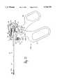
- FIG. 1is a schematic side elevational view of an embodiment of the surgical instrument of the present invention.
- FIG. 2is a schematic side elevational view of a handle assembly the surgical instrument of FIG. 1.
- FIG. 3depicts the blades of a scissor type jaw assembly in accordance with the present invention in an open position.
- FIG. 4depicts the blades of a scissor type jaw assembly in accordance with the present invention in a closed position.
- FIG. 5depicts a scissor type jaw assembly and extension in accordance with the present invention with the extension out of engagement with the jaw assembly.
- FIG. 6depicts the distal end of the tool assembly of the embodiment of FIG. 1.
- FIG. 7is a cut-away view depicting the jaw assembly actuation mechanism of the surgical instrument of FIG. 1 with the jaws in the open position.
- FIG. 8is a cut-away view depicting the actuation mechanism of the surgical instrument of FIG. 1 with the jaws in the closed position.
- FIG. 9depicts the extension of the surgical instrument of the present invention.
- FIG. 10shows the tool assembly of the surgical instrument of FIG. 1 in a cleaning configuration.
- FIG. 11is a schematic side elevational view of another embodiment of the surgical instrument of the present invention.
- FIG. 12is a schematic side elevational view of a handle assembly and extension of the surgical instrument of FIG. 11.
- FIG. 13is a cross-sectional view of the distal end of a sleeve in accordance with an embodiment of the present invention.
- FIG. 14is a cross-sectional view of the distal end of a sleeve spread open to receive a jaw assembly in accordance with the present invention.
- FIG. 15is a cross-sectional view of the distal end of a sleeve spread open and receiving a jaw assembly in accordance with an embodiment of the present invention.
- FIG. 16is a cross-sectional view of the distal end of a sleeve with a jaw assembly installed in accordance with the present invention.
- FIG. 17is a perspective view of an insertion tool loaded with jaw assembly.
- FIG. 18is a perspective view of the insertion tool and the distal end of a sleeve before the jaw assembly insertion process.
- FIG. 19is a perspective view of the insertion tool and the distal end of a sleeve during the jaw assembly insertion process.
- FIG. 20is a perspective view of the insertion tool and the distal end of a sleeve after the jaw assembly insertion process.
- FIG. 21is a perspective view of an embodiment of an insertion/removal tool in accordance with the present invention.
- FIG. 22is a schematic side elevational view of a rotatable-port embodiment of a handle assembly in accordance with the present invention.
- FIG. 23is a schematic side elevational view of the rotatable-port handle assembly of FIG. 22 showing the tool actuation process.
- FIG. 24is a schematic exploded perspective view of the rotatable-port handle assembly.
- FIG. 25is a schematic side elevational view of the housing and finger loop of the rotatable-port handle assembly.
- FIG. 26ais a schematic side elevational view of the rotatable-port handle assembly in the scissor configuration.
- FIG. 26bis a cross-sectional view taken at line A--A of FIG. 25a.
- FIG. 27is a schematic elevational view of the housing of the rotatable-port handle assembly.
- FIG. 28is a schematic elevational view of the finger loop of the rotatable-port handle assembly.
- FIG. 29is a schematic elevational view of the thumb loop of the rot table-port handle assembly.
- FIG. 30ais a schematic elevational view of the drive cog of the rotatable-port handle assembly.
- FIG. 30bis a schematic elevational view of the drive cog of FIG. 30a rotated 90°.
- FIG. 31ais a schematic elevational view of the trigger of the rotatable-port handle assembly.
- FIG. 31bis a schematic elevational view of the trigger of FIG. 31a rotated 90°.
- FIG. 32is a schematic elevational view of the slide member of the rotatable-port handle assembly.
- FIG. 33a schematic perspective view of the trigger and slide member of the rotatable-port handle assembly with the slide member at the top of the trigger.
- FIG. 33bis a schematic perspective view of the trigger and slide member of-the rotatable-port handle assembly with the slide member at the bottom of the trigger.
- FIGS. 34a-34fare schematic side elevational views of the disks, drive cog, trigger, and slide member of the rotatable-port handle assembly of the present invention, showing various steps in the rotation process.
- FIGS. 35a-35fare cross-sectional views corresponding to FIGS. 34a-34f.
- FIG. 36is a cross-sectional view of an embodiment of a removable jaw assembly in accordance with the present invention.
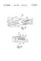
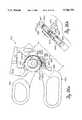
- FIG. 1is a side elevational view of an embodiment of the surgical instrument 10 of the present invention.
- FIG. 1depicts a tool assembly 12 retained in a handle assembly 14.
- the tool assembly 12comprises an inner extension 16 located inside a sleeve 18 and a scissor type jaw assembly 66 attached to the sleeve 18 via a pivot pin 68.
- a non-conductive cover 20covers the sleeve 18.
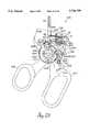
- the handle 14comprises a housing or base 50 and a tool actuation trigger or thumb loop 52 pivotably mounted to the base 50 via pivot 54.
- the base 50comprises a finger loop 51. During normal use of the instrument, the user places his fingers in the finger loop 51 to steady the base 50 and places his thumb through the thumb loop or actuation trigger 52 to actuate the tool assembly.
- the handle 14also comprises a port 17 in which the tool assembly 12 is retained.
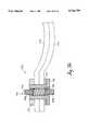
- the inner extension 16is longitudinally translatable relative to the sleeve 18.
- the inner extension 16comprises three parts: the center span 22, a proximal end 26, and a distal end 64.
- the distal end 64 of the extension 16engages the jaw assembly 66.
- the distal end of the extension 16engages the proximal ends of the jaws 70 and 72 to cause them to close.
- the distal end of the extension 16engages the jaws 70 and 72 to cause them to open.
- the extension 16is sealed to the inside surface of the sleeve 18 by O-ring 32.
- the O-ring 32is mounted in a slot 24 in the extension 16.
- the O-ringcontacts the inside surface of the sleeve 18, thus sealing the extension 16 to the sleeve 18.
- This sealprevents body fluids and gases such as carbon dioxide from traveling to the proximal end of the tool assembly 12 during surgery. It also prevents cleaning fluids from traveling to the proximal end of the tool assembly 12 during a cleaning process to be described below in detail.
- the tool assembly 12can be rotated about its longitudinal axis as a single unit within the handle 14.
- Rotating knob 42is attached to the sleeve 18.
- the extension 16 and sleeve 18are coupled to each other via a pin 34 in the extension 16 and a slot 35 in the sleeve 18.
- the pin 34is pressed into a hole 102 in the extension 16 and protrudes from the extension 16.
- a slot 35is cut in the wall of the sleeve 18.
- the extension 16 and sleeve 18are assembled such that the end of pin 34 protrudes into the slot 35.
- the userrotates the rotating knob 42. This imparts rotational motion to the sleeve 18. Because the extension 16 and sleeve 18 are coupled by the pin 34 and slot 35 as described above, the extension 16 also rotates. When the sleeve 18 and extension 16 are rotated, the jaw assembly 66 is carried in the rotation by pivot pin 68.
- the rotation of the tool assembly 12is controlled such that the tool assembly 12 is rotated within certain indexed increments. This is accomplished by the index rotator 37, the spring 36, and the detent 44.
- the index rotator 37is fixedly attached to the sleeve 18.
- the detent 44is biased by spring 36 to engage the teeth on the outer surface of the index rotator 37.
- the detent 44moves in and out of meshing engagement with the grooves on the index rotator 37.
- the spring 36provides sufficient force to the detent 44 to maintain the index rotator 37 and the tool assembly 12 stationary against inadvertent rotation.
- the tool assembly 12is retained within the port 17 of the handle 14 by engagement of the tapered end 63 of the spring-loaded retaining knob 60 with the retention groove 62 on the rotating knob 42.
- the retaining knob 60is spring biased by spring 61 toward the engagement position. When the tool assembly 12 is inserted into the port 17, the end 63 of retaining knob 60 engages the retention groove 62 to retain the tool assembly 12 in place.
- actuation of the jaw assembly 66is controlled by the longitudinal translation of the extension 16 within the sleeve 18. This longitudinal translation is controlled by the actuation trigger 52 of the handle 14.
- a spool 28is fixedly attached to the proximal end 26 of the extension 16. The spool 28 is retained on the proximal end 26 of the extension 16 by retaining clip 30.
- the extension 16When the actuation trigger 52 is rotated in the counter-clockwise direction, the extension 16 is translated forward toward the distal end of the surgical instrument 10. This distal translation of the extension 16 causes the jaws 70 and 72 to open.
- the actuation trigger 52is spring biased by return torsion spring 55.
- the return spring 55biases rotation of the actuation trigger 52 in the counter-clockwise direction. This bias tends to translate the extension 16 toward the distal end of the tool assembly 12 and thus tends to open the jaws 70 and 72.
- One end 43 of the return spring 55is fixedly attached to the actuation trigger 52, and the other end 41 is fixedly attached to the handle base 50.
- the return spring 55is radially compressed before attachment to the instrument such that the counter-clockwise rotational bias is attained. In the embodiment of FIG. 1, as shown, the return spring 55 is compressed as far as possible because the actuation trigger 52 is rotated as far as possible in the clockwise direction in opposition to the bias.
- the surgical instrument 10 of the present inventionalso provides for the electrical connections required for cautery procedures. These electrical connections are effected via the electrical connection port 49 in the handle 14.
- the electrically conducting spring clip 46is exposed to the interior of the port 49.
- the clip 46runs distally toward the front of the handle to spring 36 and detent 44.
- the distal end of the spring clipis squeezed between the spring 36 and the detent 44 thus making a connection to the index rotator 37.
- the spring clip 46, the detent 44, the index rotator 37, the sleeve 18, and the jaw assembly 66are all electrically conducting. Therefore, an electrical connection is made from the electrical connection port 49 to the jaw assembly 66.
- an electrical connectioncan be made via an electrical connector 48 inserted into electrical connection port 49.
- the non-conductive cover 20 on the outside of the sleeve 18serves to insulate the electrified sleeve 18 from tissue in the body. This allows the user to limit the cautery operation to a well defined area of tissue.
- the tool assembly 12 and the handle 14are detachable.
- the userslides the spring-loaded retaining knob 60 down in the direction shown by arrow 59. This causes the end 63 of the knob 60 to disengage the retention groove 62 in the rotating knob 42.
- the usermay grasp the rotating knob 42 and pull the tool assembly 12 distally out of the port 17.
- the usermay, while holding knob 60 down, rotate the actuation trigger 52 as far as possible in the counter-clockwise direction. This will cause tab 56 to disengage translation groove 65 in spool 28.
- tab 58will engage the back side of spool 28 to urge the extension 16 and the tool assembly 12 out of the port 17. After the spool 28 clears the tabs 56 and 58, the user may simply slide the tool assembly 12 the rest of the way out of the port 17.
- FIG. 2shows the handle 14 of the surgical instrument 10 of FIG. 1 with the tool assembly 12 removed.
- the userfirst rotates the actuation trigger 52 as far as possible in the counter-clockwise direction (shown in phantom lines). This causes tab 58 to protrude into the port 17.
- the usersimply slides a tool assembly 12 into the port 17. Because the end 63 of the retaining knob 60 is tapered, the user need not slide the knob 60 out of the way to allow the tool assembly 12 to slide back into the port 17.
- the knob 60will simply be moved out of the way by interfering pieces of the tool assembly 12 until the retention groove 62 in the rotating knob 42 is engaged by the end 63 of the knob 60.
- the spool 28slides back within the port 17. As it does so, the back side of the spool 28 engages the tab 58 protruding into the port 17. The rearward motion of the spool 28 forces the tab 58 out of the way by forcing the actuation trigger 52 to rotate in the clockwise direction. The back ridge portion 29 of the spool 28 then engages with the groove 57 between tabs 56 and 58 on the actuation trigger 52. Finally, as the spool 28 slides all the way back into the port 17, the rotation of the actuation trigger 52 causes the tab 56 to engage the translation groove 65 on the spool 28. When the end 63 of the knob 60 engages with the retention groove 62 on the rotating knob 42, the tool assembly 12 is retained within the handle 14 and is ready for use.
- the tool assembly 12is also provided with a cleaning port 40 in the rotating knob 42.
- This port 40allows for the introduction of cleaning fluid into the tool assembly 12.
- the port 40is a luer taper configuration.
- a syringe full of cleaning fluid (not shown) having an end with a mating luer tapermay be inserted into the port 40.
- the cleaning fluidis then introduced into the interior of the tool assembly 12 between the extension 16 and the inside surface of the sleeve 18. As will be described below in detail, this cleaning process may be performed when the tool assembly 12 is removed from the handle 14.
- the proximal end of the port 17prevents the spool from moving back proximally far enough for the O-ring seal 32 to travel to the proximal side of the cleaning port 40.
- the O-ring seal 32positioned as shown in FIG. 1, prevents body fluids from traveling up the tool assembly 12 to the handle 14.
- the cleaning processis carried out with the tool assembly detached from the handle. With the tool assembly detached, the proximal end of the port 17 does not interfere with the travel of the extension 16.
- the O-ring seal 32can be positioned on the proximal side of the cleaning port 40. Cleaning fluid enters the tool assembly 12 via the port 40 and runs to the distal end of the tool assembly 12. In other embodiments, the proximal end of the port 17 does not inhibit travel of the extension 16. In these embodiments, the cleaning process can be performed with the tool assembly attached to the handle.
- FIGS. 3 and 4depict a scissor type embodiment of the jaw assembly 66 used in the surgical instrument 10 of the present invention shown in open and closed positions, respectively.
- jaws 70 and 72are shown pivotably mounted to each other via pivot 68.
- Jaw 70comprises cutting surface 74
- jaw 72comprises cutting surface 76.
- Depressions 78 and 80 in jaws 70 and 72respectively allow the jaws to mesh properly as they pivot throughout their range of operation.
- the distal end of each jawis twisted with respect to the proximal end of each jaw such that the jaws are biased toward each other by opposing angles to provide a proper positive cutting action during operation.
- the twist angle of each jawis approximately 2.5°.
- Each jawalso comprises an open ended slot at its proximal end.
- Jaw 72comprises open ended slot 82
- jaw 70comprises open ended slot 84.
- the open ended slots 82 and 84are engageable by drive pin 86. It should be noted that drive pin 86 is not part of the jaw assembly 66; it is coupled to the distal end 64 of the inner extension 16 as described below in connection with FIG. 9.
- FIG. 3shows the drive pin 86 positioned as far as possible toward the distal end of the jaw assembly 66.
- the jawsare in an open position. If the drive pin 86 is moved toward the proximal ends of the slots 82 and 84, the jaws 70 and 72 will tend to move toward a closed position. As the drive pin 86 is moved proximally, it engages the inner wall 87 of slot 82 and the inner wall 88 of slot 84. This causes the inner walls of the slots to spread apart from each other and further causes the jaws 70 and 72 to close.
- FIG. 4depicts the jaws 70 and 72 in the closed position.
- Drive pin 86has been moved out to the proximal ends of slots 82 and 84. It should be noted that further proximal translation of the drive pin 86 will cause the drive pin 86 to disengage the slots 82 and 84, but such translation is normally prevented by the handle assembly.
- the proximal ends of the jaws 70 and 72are formed at angles which ensure proper engagement of the drive pin 86. When the drive pin 86 is disengaged from the slots in the jaws, distal translation of the drive pin 86 will cause it to engage the slots regardless of the pivotal orientation of the blades with respect to each other, even though the slots are not aligned. This effect is due to the angles at which the proximal ends of the jaws are formed.
- the drive pin 86can be translated within the slots 82 and 84 toward the distal end of the jaws 70 and 72. As the drive pin 86 moves along the slots, it engages inner wall 92 of slot 82 and inner wall 90 of slot 84 to drive the blades apart.
- the angled side surfaces 94 and 96 on jaws 72 and 70 respectivelyare provided to prevent the jaws from interfering with the sleeve 18 when the jaws are in an open position. They also serve as a stop to prevent the jaws 70 and 72 from pivoting too far when the drive pin 86 is disengaged from the slots.
- FIG. 5depicts a jaw assembly 66 and the distal end of the extension 16 of the present invention.
- the distal end of the extension 16comprises a clevis 104 which carries the drive pin 86.
- the drive pin 86spans a gap 106 in the clevis 104.
- the clevis 104 and drive pin 86are shown out of engagement with the proximal ends of the jaws 70 and 72.
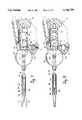
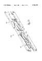
- FIG. 6depicts the distal end of the tool assembly 12.
- the jaw assembly 66is shown attached to the sleeve 18 by the pivot pin 68.
- the distal end of the extension 16is shown within the sleeve 18.
- the extension 16comprises the distal end of the center span 22 attached to the clevis 104. The details of the extension 16 will be-described below in detail.
- the drive pin 86 carried by the clevis 104is shown engaging the proximal ends of the jaws 70 and 72.
- FIGS. 7 and 8depict the relationship between the position of the spool 28 within the port 17 of the handle 14 and the position of the jaws 70 and 72.
- FIG. 7depicts the configuration in which the jaws are open
- FIG. 8depicts the configuration in which the jaws are closed.
- the tool assembly 12is shown retained in the port 17 of the handle 14.
- the end 63 of the spring-loaded retention knob 60is shown in engagement with the retention groove 62 on the rotating knob 42.
- spool 28is shown translated toward the distal end of the port 17. Consequently, extension 16 is translated toward the distal end of the tool assembly 12.
- Pin 34 in the extension 16is shown at the distal end of slot 35 in the sleeve 18.
- drive pin 86is located at the distal ends of slots 82 and 84 of the jaws 70 and 72. As a result, the jaws are in the open position.
- FIG. 8the closed-jaws configuration is depicted.
- Spool 28has been translated to the proximal end of the port 17.
- the extension 16has been pulled back in the proximal direction.
- Pin 34 in the extension 16is located half way between the distal end and the proximal end of the slot 35 in the sleeve 18.
- the pin 34is located at the distal end of the slot 35.
- the distal end 64 of the extension 16is shown pulled back in the proximal direction.
- drive pin 86is located at the proximal end of the slots 82 and 84, and the jaws 70 and 72 are in the closed position.
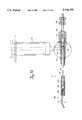
- FIG. 9shows the details of the extension 16.
- the extension 16is comprised of three sections. These are the proximal end 26, the center span 22, and the distal end 64.
- the spool 28is retained on the proximal end 26 of the extension 16.
- the spool 28slides over the proximal end of the extension 16 and rests against shoulder 100.
- a retaining clip 30slides into groove 98 to retain the spool 28 in place.
- Pin 34(see FIG. 1) is pressed into hole 102 such that the end of pin 34 protrudes out one side of hole 102.
- O-ring seal 32(see FIG. 1) rests within groove 24.
- the center span 22 of the extension 16is attached to the proximal end 26 of the extension 16 via hole 25 in the proximal end of the extension 16.
- the center span 22is inserted into the hole 25 and permanently staked in place.
- the center span 22is staked to a clevis 104 located at the distal end 64 of the extension 16.
- the center span 22is inserted in hole 103 in the clevis and permanently staked in place.
- the drive pin 86(see FIG. 2) spans across a gap 106 in the clevis 104. This gap 106 provides clearance for the proximal ends of the jaws when the drive pin 86 engages the slots in the jaws.
- FIG. 10depicts the cleaning configuration of the tool assembly 12.
- the tool assembly 12has been removed from the handle 14.
- the extension 16has been pulled back within the sleeve 18 to a cleaning position.
- Pin 34 in the extension 16is shown at the extreme proximal end of the slot 35 in sleeve 18.
- the extension 16in the cleaning position, is pulled back proximally far enough within the sleeve 18 to allow the O-ring seal 32 to move to the proximal side of the cleaning port 40.
- Cleaning fluidis introduced into the tool assembly 12 from syringe 101 via the cleaning port 40. Because the extension 16 is in the cleaning position, the O-ring seal 32 prevents the cleaning fluid from traveling toward the proximal end of the tool assembly 12. The cleaning fluid enters the port 40 and travels down the tool assembly 12 and out to the jaw assembly 66. This effects a cleaning operation of the inside of the tool assembly 12. Also, the fluid running out of the distal end of the tool assembly 12 cleans the jaw assembly 66 as well.
- the drive pin 86 at the distal end of the extension 16is no longer in engagement with the proximal ends of the jaws 70 and 72.
- the extension 16has been drawn back toward the proximal end of the tool assembly 12 such that the pin 86 has disengaged the slots at the proximal ends of the jaws.
- the open ended slots 82 and 84 at the proximal ends of the jaws 72 and 70facilitate the full translation of the extension to properly position the O-ring seal 32 during the cleaning operation.
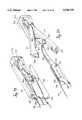
- FIG. 11depicts another embodiment 210 of the surgical instrument of the present invention.
- longitudinal translation of the extension 16causes the jaws 70 and 72 to pivot between open and closed positions.
- the sleeve 218is retained within the handle 214 with the spring-loaded retaining knob 60 in engagement with retention groove 62 on rotating knob 42.
- Spring 61biases the knob 60 toward the engagement position.
- Index rotator 37, detent 44, and spring 36once again provide for indexed rotation of tool assembly 212. Electrical connections are provided in identical fashion to that of the previous embodiment.
- Translation of the extension 16 within the sleeve 218is initiated by rotation of the thumb loop or actuation trigger 52 about pivot 54.
- Tab 56 on actuation trigger 52engages translation groove 65 on spool 28 to translate the extension 16 back and forth with rotation of the actuation trigger 52.
- a difference between this embodiment and the previous embodimentis in the detachment and replacement of parts of the tool assembly 12.
- this embodimentonly the sleeve 218 and jaw assembly 66 can be removed from the handle 214.
- the extension 16remains permanently fixed within the handle 214.
- the userslides the spring-loaded retaining knob 60 out of engagement with the retention groove 62.
- the usergrasps the rotating knob 42 and pulls the sleeve 218 out of the port 17 of the handle 214.
- the slot 135 in the sleeve 218has an open proximal end. This allows pin 34, which is pressed into extension 16 as in the prior embodiment, to slide out of the slot 135 without interference.
- the extension 16is permanently mounted within the handle 214.
- tab 56is prevented from disengaging translation groove 65 in spool 28 by a limitation on the counter-clockwise rotation of the actuation trigger 52. This is effected by the interior structure of the base portion 250 of the handle 214. Specifically, a wall 220 is provided in the base 250 of the handle 214. As the actuation trigger 52 is rotated counter-clockwise, the wall 222 of the trigger interferes with wall 220. This prevents the actuation trigger 52 from rotating far enough to allow spool 28 to clear tabs 56 and 58 on the actuation trigger 52.
- Cleaningis accomplished in this embodiment by simply introducing cleaning fluid into the proximal end of the sleeve 218 after it has been removed from the handle 214.
- the sleeve 218may be provided with a cleaning port to allow the cleaning fluid to be introduced. The cleaning fluid runs down through the sleeve 218 and out the distal end of the sleeve 218 into the jaw assembly 66. The extension 16 is exposed for cleaning separately.
- the jaw assembly 66is mounted to the sleeve 218 via pivot pin 68.
- the jaws 70 and 72pivot about the pivot pin 68 when actuated by the drive pin 86 at the distal end of the extension 16.
- the jaw assembly 66is changed by simply installing a new sleeve 218 with attached jaw assembly 66 over the extension 216 and into the handle 214.
- FIG. 12depicts the surgical instrument 210 with the sleeve 218 and jaw assembly 66 removed.
- the extension 16is retained within the port 17 of the handle 214.
- the tab 56 on actuation trigger 52remains engaged with the translation groove 65 on spool 28. This engagement prevents the extension 16 from sliding out of the port 17.
- the actuation trigger 52is prevented from rotating in the counter-clockwise direction by the interference between the wall surface 222 on the actuation trigger 52 and the wall surface 220 on the base 250 of the handle assembly 214.
- the jaw assemblymay also be removeably-attached to the distal end of the sleeve. This alternate means of jaw assembly attachment may be used in any embodiment of the surgical instrument. A jaw assembly is replaced by simply removing it from the sleeve and installing a new jaw assembly as described below.
- the removable jaw assemblycan be implemented by different approaches.
- the distal end of the sleeveis made of an elastic material.
- a jaw assembly 66is installed or removed from the sleeve by spreading its distal end open to provide clearance for the pivot pin 68 of the jaw assembly 66. When the jaw assembly 66 is in position within the sleeve, the distal end closes to hold the jaw assembly in place.
- FIGS. 13 and 14are cross-sectional views of the distal end of a sleeve 318 used in this first alternate jaw assembly attachment technique.
- a tubular insert 232forms the end of the sleeve 318.
- the insert 232is made of an elastic material such as a spring steel.
- Slots 230, 236, and 237are cut into the wall of the insert by electronic discharge machining (EDM) or some other means. It should be noted that slots identical to slots 230, 236, and 237 are located on the opposite wall of the tubular insert 232. These are not seen in the cross-sectional elevational views of FIGS. 13 and 14.
- Holes 234 and 235are located in line on opposite sides of the slot 230. These holes are adapted to receive the pivot pin 68 of the jaw assembly 66 (not shown).
- the slot 230is made sufficiently wide to provide clearance for the proximal ends of the jaws 70 and 72 when they are inserted into the end of the sleeve 318.
- a jaw assembly 66is installed on the distal end of the tubular insert 232 by spreading the end of the tubular insert 232 at the slot 230 as shown in FIG. 14.
- the ends of the slot 230are spread sufficiently far apart to allow the pivot pin 68 to pass into the distal end of the tubular insert 232 and be engaged by holes 234 and 235.
- Slots 236 and 237act together as a "living hinge" to allow the tubular insert 232 to spring open and closed without causing distortions in the material.
- the tubular insert 232is shown sprung open to receive the jaw assembly 66.
- the sleeve 318is sprung open sufficiently wide to allow the pivot pin 68 of the jaw assembly 66 to pass into the slot 230.
- the sleeve 318is released to allow it to close over the pivot pin 68.
- FIG. 15is a cross-section of the distal end of the sleeve 318 showing the tubular insert 232 sprung open and receiving the jaw assembly 66. The end has been sprung sufficiently wide to allow the pivot pin 68 to pass through the slot 230. Also shown is the clevis 104 at the distal end of the extension 16. The clevis 104 carries the drive pin 86 at its distal end. Because the jaw assembly 66 has not been completely inserted into the insert 232, the drive pin 86 does not yet engage the proximal ends of jaws 70 and 72.
- FIG. 16depicts the distal end of the sleeve 318 after the jaw assembly 66 has been installed.
- the insert 232has sprung closed again, the holes 234 and 235 engaging the pivot 68 of the jaw assembly 66.
- the drive pin 86 at the distal end of the clevis 104is now shown to be engaging the slots in the proximal ends of the jaws 70 and 72.
- translation of the extension 16 toward the distal end of the sleeve 318will cause drive pin 86 to drive the jaws 70 and 72 to the open position as previously described.
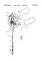
- FIG. 17is a perspective view of an insertion tool 300 in accordance with the present invention.
- the insertion tool 300is shown loaded with a jaw assembly 66.
- the jaw assembly 66rests in a housing or tray 302 of the insertion tool 300.
- the distal ends of the jawsrest against the inside wall 304 of the tray 302.
- the pivot 68rests inside a slot 306 in the back side of the tray 302 (see FIG. 20).
- Levers 312 and 314are pivotably mounted to the tray 302 via pivot pins 320 and 322 respectively.
- the proximal ends 315 and 317 of levers 312 and 314comprise wedges 324 and 326, respectively.
- the wedges 324 and 326are shaped to engage the slots 230 on the tubular insert 232 at the distal end of the sleeve 318.
- the levers 312 and 314are pivotable about pivot pins 320 and 322 between an open position and a closed position.
- FIG. 17depicts the levers in the closed position.
- the wedges 324 and 326engage the slots 230 on the tubular insert 232 of the sleeve 318.
- the wedgesengage the slots 230 to spread the end of the tubular insert 232 wide enough to allow the jaw assembly 266 to be inserted into the insert 232.
- the slot 306 in the tray 302 of the insertion tool 300allows the insertion tool to be removed from the assembled sleeve 318 and jaw assembly 66.
- FIGS. 18, 19, and 20are perspective views showing three steps in the jaw assembly insertion process.
- FIG. 18shows the distal end of the sleeve 318 without a jaw assembly 66 installed.
- the insertion tool 300is shown with a jaw assembly 66 about to be installed on the sleeve 318.
- the non-conductive cover 20is shown cut away so that details of the sleeve 318 can be viewed.
- the levers 312 and 314are pivoted to the closed position.
- the insertion processbegins as the insertion tool 300 is moved in the direction of arrow 231. Wedges 324 and 326 engage slots 230 to spread open the end of the sleeve 318. The proximal end of the jaw assembly 66 slides into the distal end of the sleeve 318.
- the insertion tool 300 and jaw assembly 66have been inserted into the distal end of the sleeve 318 with the levers 312 and 314 in the closed position.
- the wedges 324 and 326are engaged with slots 230.
- the sleevehas been spread apart at slots 230 and at the living hinge formed by slots 236 and 237.
- the holes 234 and 235 in the sleeveare spread far enough apart to allow the pivot pin 68 to pass between the holes 234 and 235.
- the holes 234 and 235are aligned with the pivot 68 such that when the sleeve 318 is allowed to spring closed again, the jaw assembly 66 will be held within the sleeve 318 by the engagement of the holes 234 and 235 with the pivot 68.
- FIG. 20depicts the distal end of the sleeve 318 with the jaw assembly 66 installed.
- the sleeve 318has closed down such that the pivot pin 68 of the jaw assembly 66 is retained in holes 234 and 235.
- the insertion tool 300is shown in proximity to the sleeve 318 without a jaw assembly 66.
- the empty insertion tool 300may be discarded or it may be retained for removal of a dull jaw assembly 66 from another sleeve 318.
- FIG. 21is a perspective view of an insertion/removal tool 400 in accordance with the present invention.
- the insertion end 401 of the tool 400is similar to the insertion tool 300 described above in connection with FIG. 17.
- a jaw assembly 66is loaded in the housing 402 and is ready for insertion into a sleeve of a surgical tool assembly.
- the removal end 403 of the insertion/removal tool 400is identical to the insertion end 401, except that a jaw assembly is not loaded in the housing 405.
- the removal end 403is used to remove a jaw assembly 66 from the end of a tool assembly as described above in connection with FIGS. 18-20.
- the insertion/removal tool 400is used to change jaw assemblies on a tool assembly. First, the removal end 403 is used to remove the old jaw assembly. After the old jaw assembly is removed, the insertion end 401 is used to install a fresh one. After the process is completed, the insertion/removal tool 400 with the old jaw assembly may be discarded.
- FIG. 36depicts another embodiment of a removable jaw assembly 700.
- the jaws 770 and 772are attached to each other by a compressible pivot 701.
- the pivot 701holds the jaw assembly 700 in place in the distal end of tool assembly sleeve.
- the compressible pivot 701comprises two pivot ends 702 and 704 biased away from each other by partially compressed coil spring 708.
- the jaw assembly 700is assembled by first installing pivot end 704 in the void 706 in tubular member 714. Next, the coil spring 708 is installed. The pivot end 702 is forced into the void 706 against the spring force of the coil spring 708. The pivot ends 702 and 704 and the spring 708 are then staked in place within the void 706 of the tubular member 714.
- the tubular member 714is then inserted through a spring washer 712 and then through holes in the jaws 770 and 772.
- a flange 710is pressed onto the tubular member 714 to hold the jaw assembly 700 together.
- the spring washer 712maintains compression between the jaw blades 770 and 772 to ensure proper operation.
- the pivot ends 702 and 704are compressed toward each other.
- the jaw assembly 700is then made to slide into the distal end of the sleeve.
- the ends 702 and 704come into alignment with holes through opposite walls of the sleeve, they snap into engagement with the holes to hold the jaw assembly 700 in place.
- the pivot ends 702 and 704are compressed toward each other sufficiently to allow them to clear the holes in the walls of the sleeve.
- the jaw assembly 700is then caused to slide out of the sleeve.
- the handle assemblycan also be provided in a dual-port configuration as described in U.S. patent application Ser. No. 07/903,162 of which this application is a continuation-in-part.
- pivoting of the triggerprovides translation motion in both of the two ports.
- the tool assemblycan be inserted into either of the ports.
- the handle assembly of the present inventioncan also be provided in a rotatable-port or universal-port configuration.
- the rotatable-port handle assemblycomprises a base or housing which has a single port in which a tool assembly 12 is retained and actuated.
- a finger loop and a thumb loop or actuation triggerare pivotably mounted to the housing.
- relative rotational motion between the thumb loop and the finger loopprovides translational motion to the port to actuate the tool assembly.
- the rotatable-port handle 500is operable in either of two configurations--a pistol configuration and a scissor configuration.
- the pistol configurationis depicted in FIG. 22.
- the finger loop 550is fixed to the housing 502 in the orientation shown.
- the thumb loop or actuation trigger 552is pivotable relative to the finger loop 550 to actuate the tool assembly 12.
- the scissor configurationis shown in FIG. 26a.
- the finger loop 550is fixed to the housing 502 in the orientation shown.
- the thumb loop 552is pivotable relative to the finger loop 550 to actuate the tool assembly.
- the finger loop 550 and thumb loop 552can be readily positioned in either the pistol or scissor configuration.
- a release trigger 602locks the handle assembly 500 in either of the positions.
- the release trigger 602is rotated to its open position to release the handle 500 from its present configuration.
- the thumb loop 552 and finger loop 550are then rotated until the release trigger 602 locks them in the new position.
- FIG. 24shows the interaction of the parts of the rotatable-port handle assembly 500.
- the housing 502 and top cover 503come together to form the port 517 for a tool assembly (not shown).
- the housing 502is formed with a housing disk 627.
- the housing disk 627has a pistol configuration notch 620 and a scissor configuration notch 632 formed in its outer circumference.
- the finger loop 550is formed with a finger disk 624 which lays over the housing disk 627 when the handle 500 is assembled.
- the release trigger 602is pivotably mounted to the finger loop 550.
- the trigger key 612engages finger notch 618 on the finger disk 624 and notch 620 on the housing disk 627 when the handle is in the pistol configuration. In the scissor configuration, the trigger key 612 engages notches 618 and 632.
- a slide member 600is coupled to the release trigger 602.
- the slide member 600is permitted to slide along the release trigger 602 guided by a rail 646 on the release trigger 602 mated with a groove 648 in the slide member 600.
- the slide member 600has a slide key 610 which does not engage the notch 618 on the finger disk 624. So, even when the trigger key 612 is engaged with notch 618, the slide member 600 is free to slide independent of the release trigger 602.
- the thumb loop 552is formed with a thumb disk 622 having a notch 616 formed in its outer surface.
- the thumb disk 622lays over the finger disk 624 in the handle 500, and a drive cog 504 lays over the thumb disk 622.
- the drive cog 504is formed with a tab 556 which actuates the tool assembly when the drive cog 504 is assembled in the instrument.
- the drive cog 504is fixed to the thumb disk 622.
- the drive cog 504rotates with it to actuate the tool assembly.
- the thumb disk 622 and drive cog 504are held together by the slide key 610.
- the slide key 610engages thumb notch 616 and one of the notches 614 and 630 on the drive cog 504.
- the slide key 610engages notch 616 and the drive cog pistol configuration notch 614.
- the scissor configurationthe slide key 610 engages notch 616 and the scissor configuration notch 630.
- the release trigger 602is in its closed position.
- the trigger key 612engages notches 618 and 620
- the slide key 610engages notches 614 and 616.
- the thumb loop 552is rotated relative to the finger loop 550 to actuate a tool assembly.
- the slide member 600slides along the release trigger 602, carried by the engagement between the notches 614, 616 and the slide key 610.
- the slide key 610fixes the drive cog 504 to the thumb loop 552.
- the tab 556translates within the port 517 to actuate the tool assembly.
- FIG. 22is a side elevational view of the rotatable-port or universal-port handle assembly 500 in accordance with the present invention.
- the handle assembly 500comprises the housing or base 502 having the port 517 in which a tool assembly 12 is retained and actuated in accordance with the foregoing description.
- the thumb loop or actuation trigger 552 and the finger loop 550are pivotably mounted to the housing 502 by pivot 554.
- the thumb loop 552 and finger loop 550are pivotable relative to each other and relative to the housing 502.
- the drive cog 504is pivotably mounted to the finger loop 550, the thumb loop 552 and the housing 502 by pivot 554.
- the drive cog 504comprises the tab 556 on its outer diameter which engages the translation groove 65 in the spool 28 of a tool assembly 12 as previously described. As the drive cog 504 is caused to rotate about pivot 554, the spool 28 is translated back and forth to actuate the tool assembly 12.
- the release trigger 602is pivotably mounted to the finger loop 500 by pivot 604.
- a slide member 600is slidably mounted on the release trigger 602.
- the release trigger 602comprises a depression end 606 and a key end 608.
- the trigger key 612is located at the key end 608 of the release trigger 602.
- the slide key 610 of the slide member 600is shown in FIG. 22 in alignment with the trigger key 612. Thus, in the elevational view, the trigger key 612 cannot be seen because it is behind the slide key 610 of the slide member 600.
- the slide key 610engages notch 614 on the outer surface of the drive cog 504 and notch 616 on the thumb disk 622 of the thumb loop 552 during actuation of the tool assembly 12. This eliminates rotational movement between the drive cog 504 and the thumb loop 552. Thus, when the thumb loop 552 is rotated about pivot 554, the drive cog 504 is carried with it. As the drive cog 504 rotates, tab 556 causes the spool 28 to translate longitudinally within the port 517 to actuate the tool assembly 12.
- the finger loop 550is prevented from rotating with respect to the housing 502 by the release trigger 602.
- the trigger key 612 on the release trigger 602engages notch 618 on the finger disk 624 of the finger loop 550 and notch 620 on the housing disk 627 (see FIG. 24) on the housing 502.
- the finger loop 550 and the housing 502are in a fixed relationship to each other. The interactions and relationships among the various disks, notches, and keys will be described below in greater detail.
- the release trigger 602is spring loaded. Coil spring 626 biases the release trigger 602 in the counter-clockwise rotational direction toward the closed or engagement position depicted in FIG. 22. Pressing the depression end 606 of the release trigger 602 causes the release trigger 602 to rotate in the clockwise direction about pivot 604 against the biasing force of coil spring 626. Trigger key 612 comes out of engagement with notches 618 and 620. Slide member 600 is carried with the release trigger 602 such that the slide key 610 comes out of engagement with notches 614 and 616. When the trigger 602 is released, if the notches line up with their corresponding keys, the coil spring 626 forces the trigger 602 to pivot such that the keys drop into engagement with the notches.
- the handle assembly 500is operable in two possible configurations, the pistol configuration shown in FIG. 22 and a scissor configuration shown in FIGS. 26a and 26b.
- the instrumentmay be changed from one configuration to the other by rotating the finger loop 550 and thumb loop 552 with respect to the housing 502 and the drive cog 504. As an illustration, the process of rotating from the pistol configuration to the scissor configuration will be described.
- the rotation processis carried out by depressing the release trigger 602 to release the drive cog 504 and the various disks from each other.
- the thumb loop 552 and finger loop 550are rotated to the new position while the housing 502 and drive cog 504 remain stationary.
- the release trigger 602closes.
- the slide key 610 on the slide member 600drops into engagement with the notch 616 on the thumb disk 622 and a scissor configuration notch 630 on the drive cog 504 to lock the two together.
- the trigger key 612engages the notch 618 on the finger disk 624 and a scissor configuration housing disk notch 632 (see FIG. 24) to lock the handle 500 in the configuration.
- the tool assembly 12is retained within the port 518 in a manner similar to that described for the other embodiments.
- the tapered end 563 of spring-loaded knob 560engages the retention groove 62 in the tool assembly 12.
- a coil spring 561biases the knob 560 toward the engagement position.
- the knobis forced to slide in the direction indicated by the arrow 559 against the biasing force of coil spring 561 until the end 563 of the knob 560 slides out of engagement with the retention groove 62.
- the taper on the end 563 of the knob 560allows the knob 560 to be forced out of the way as the tool assembly slides into the port 517.
- the end 563 of the knob 560snaps into engagement with the retention groove 62 as the tool assembly 12 slides all the way back into the port 517.
- a torsion spring 555couples the drive cog 504 to the top cover 503 of the housing 502 (see FIG. 24).
- the function of the torsion spring 555is similar to that of the torsion spring 55 in the other embodiments.
- the spring 555biases the rotation of the drive cog 504 in a clockwise direction to locate the tab 558 within the port 517 during installation of a tool assembly 12 to ensure proper installation.
- the rotatable-port handle assembly 500also provides for electrical connections to the tool assembly 12 via electrical connection port 549.
- An electrical connector 48is inserted in port 549.
- the spring clip 546provides an electrical connection from the connector 48 to the index rotator 37 fixed to the tool assembly 12.
- Coil spring 536applies force to detent 544.
- the detent 544rides on the outer surface of index rotator 37 to provide indexed rotation of the tool assembly 12.
- the spring clip 546is squeezed between the spring 536 and the detent 544.
- the electrical connectionis provided to the tool assembly 12.
- FIG. 23depicts the operation of the handle assembly 500 during actuation of the tool assembly 12.
- the thumb loop 552is rotated in the direction indicated by arrow 640
- the thumb disk 622 and the drive cog 504rotate in the direction indicated by the arrow 641.
- Tab 556imparts translational motion to the spool 28 and extension 16 of the tool assembly 12 as indicated by arrow 642 to actuate the tool assembly 12.
- the slide key 610 of the slide member 600has engaged notch 614 in the drive cog 504 and notch 616 in thumb disk 622. Consequently, the drive cog 504 rotates with the thumb loop 552. Also, the trigger key 612 on the release trigger 602 has n engaged notch 618 on the finger disk 624 of the finger loop 550 and the notch 620 in the housing disk 627. Therefore, the finger loop 550 is held stationary with respect to the housing 502.
- FIG. 23also illustrates the operation of the release trigger 602 and slide member 600 while the tool assembly is being actuated.
- the slide member 600is carried along the release trigger 602 via the interference between the walls of the notches 614 and 616 and the slide key 610.
- the slide member 600slides along the release trigger 602 guided by slide rail 646 in the trigger release 602 and a meshing slide groove 648 in the slide member 600 (see FIG. 33b).
- the slot 650 in the slide member 600slides along pivot 604. The slot 650 can serve to limit the travel of the slide member 600.
- FIG. 24is a schematic exploded view of the handle assembly 500 of the present invention.
- the housing 502comprises the port 517 for a tool assembly. Also shown is the housing disk 627.
- the housing disk 627is an integral part of the housing 502.
- the housing 502is molded with the disk 627 formed as shown.
- the housing disk 627comprises a notch 620 and a notch 632 on its outer diameter.
- the trigger key 612 on the release trigger 602meshes with one of these notches. If the handle 500 is in the pistol configuration (FIG. 23), the trigger key 612 meshes with notch 620. In the scissor configuration (FIG. 26a), the trigger key 612 meshes with notch 632.
- the finger loop 550is shown with the release trigger 602 attached at pivot 604.
- the slide member 600is shown slideably attached to the release trigger 602.
- the slide member 600slides along the release trigger 602 guided by the mating rail 646 in the release trigger 602 and groove 648 in the slide member 600.
- Pivot 604passes through slot 650 in the slide member 600.
- the groove 650 and pivot 604guide the sliding of the slide member 600 as well as limit the extent of its travel.
- the slide key 610 of the slide member 600is shown aligned with the trigger key 612. However, this need not be the case.
- the release trigger 602is in the closed position so that the trigger key 612 meshes with notch 618 in the finger disk 624. But, slide key 610 in the slide member 600 does not mesh with the notch 618. Therefore, when the thumb loop 552 and finger loop 550 rotate relative to each other, the slide member 600 is free to slide independent of the release trigger 602.
- the back surface 623 of the finger disk 624contacts the front surface 629 of the housing disk 627 when the handle 500 is assembled.
- Pivot hole 652 in the housing disk 627is aligned with pivot hole 654 in the finger disk 624.
- the finger loop 550is positioned such that, when the housing is assembled, the trigger key 612 will mesh with notch 620 in the housing disk 627 when the release trigger 602 is in the closed position. With the trigger key 612 in notch 620, the handle 500 is in the pistol configuration. To change to the scissor configuration, the trigger 602 is depressed to disengage the trigger key 612 from the notches 618 and 620.
- the finger loop 550is rotated in the clockwise direction until notch 618 in the finger disk 627 is aligned with notch 632 in the housing disk 627.
- the release trigger 602then closes; the trigger key 612 falls into engagement with the notches 618 and 632 to lock the handle 500 in the scissor configuration.
- the back surface 621 of the thumb loop 552contacts the front surface 625 of the finger-loop 550 when the handle 500 is assembled.
- Pivot hole 656 in the thumb disk 622is aligned with pivot hole 654 in the finger disk 624.
- the thumb loop 552is shown oriented such that the notch 616 in the thumb disk 624 is aligned with notches 618 and 620 in the finger disk 624 and housing disk 627, respectively.
- the back surface 660 of the drive cog 504contacts the front surface 662 of the thumb disk 622 when the handle 500 is assembled.
- Pivot hole 656 in the thumb disk 622is aligned with pivot hole 658 in the drive cog 504.
- pistol notch 614 on the drive cog 504is aligned with notch 616 on the thumb disk 622.
- the tab 556 on the drive cog 504is oriented substantially vertically. Therefore, when the handle 500 is assembled, the tab 556 will extend into the port 517 to drive a tool assembly 12.
- the drive cog 504must retain essentially the same rotational orientation as that shown in FIG. 24. This orientation keeps tab 556 protruding into the port 517 to drive a tool assembly 12 in either configuration.
- the release trigger 602is depressed to disengage trigger key 612 from the finger disk notch 618 and pistol configuration notch 620 on the housing disk 627.
- slide key 610disengages thumb disk notch 616 as well as the pistol configuration notch 614 on the drive cog 504.
- the thumb loop 552 and finger loop 550are then rotated together to the scissor position while the drive cog 504 and housing disk 627 remain substantially stationary.
- the trigger key 612falls into engagement with the notches 618 and 632 to lock the finger loop 550 to the housing disk 627 in the scissor position.
- the slide key 610falls into engagement with the notches 616 and 630 to lock the thumb disk 622 to the drive cog 504 in the scissor configuration.
- the rotation processis carried out with a tool assembly 12 installed in the port 517. Frictional forces inherent in the tool assembly inhibit rotation of the drive cog 504 when the trigger is in the release or open position.
- Torsion spring 555couples the drive cog 504 to the top cover 503 of the handle 500.
- One end 666 of the spring 555is inserted into a hole 664 in the drive cog 504.
- the other end 668 of the spring 555is inserted in a hole in the back side of the cover 503 (not shown).
- the torsion spring 555tends to bias rotation of the drive cog 504 and thumb loop-552 in the clockwise direction. This clockwise bias aids during installation of a tool assembly 12 into the port 517.
- tab 558 on the drive cog 504is rotated into the port 517. During insertion of a tool assembly, the tab 558 ensures that tab 556 will rotate into proper engagement with the tool assembly.
- a pivot nut 670passes through the pivot holes 652, 654, 656, 658 in the disks and the drive cog to hold them in position.
- a pivot screw 672threads into the pivot nut 670 through the cover 503, the drive cog 504, and the disks to hold the handle assembly 500 together.
- the handle assembly 500actuates a tool assembly 12 by relative rotational motion between the finger loop 500 and thumb loop 552.
- the finger loop 550With the release trigger 602 in the closed position, the finger loop 550 is stationary with respect to the housing 502 and therefore also with respect to a tool assembly in the port 517.
- Tab 556engages the tool assembly in the port 517.
- tab 556 on the drive cog 554is carried back and forth within the port 517 to actuate the tool assembly.
- the thumb loop 552 and drive cog 504coupled together by the slide key 610, rotate with respect to the finger loop 550 and housing 503, coupled together by trigger key 612.
- This independent rotationis facilitated by the sliding motion between the release trigger 602 and the slide member 600.
- slide member 600slides along the release trigger 602.
- the slide member 602is caused to slide by the engagement of the slide key 610 with the thumb loop notch 616 and either the pistol configuration notch 614 or the scissor configuration notch 630 on the drive cog 504.
- the slide member 600is guided by the mating slide rail 646 on the release trigger 602 and slide groove 648 on the slide member 600.
- the handle assembly 500is shown in the tool-assembly-closed position. That is, the relative rotational orientation of the finger loop 550 to the thumb loop 552 is such that the tab 556 is pulled back within the port 517 to close the tool assembly jaws as previously described.
- the thumb loop 552is rotated as far as possible in the counter-clockwise direction. This can be seen by the positions of the notches 614, 616, 618, and 620 and the position of the slide member 600 with respect to the release trigger 602. The notches are all in alignment, and the slide member 600 is at the limit of its travel at the top of the release trigger 602.
- Thumb loop 552will not rotate further in the counter-clockwise direction because groove 650 in the slide member 600 and pivot 604 will prevent the slide member 600 from sliding further along the release trigger 602. Clockwise rotation of the thumb loop 552 to open tool jaws is not inhibited by the slide member 600 because slot 650 and pivot 604 will allow the slide member 600 to slide down the release trigger 602.
- FIG. 25is a schematic side elevational view of the housing 502 and the finger loop 550 of the handle assembly 500.
- the housing 502 and finger loop 550are shown during the rotation process.
- the thumb loop 552 and the drive cog 504are removed in order to clearly illustrate the rotation process as it pertains to the finger loop 550 and the housing 502.
- the slide key 600has been removed from the release trigger 602.
- the finger loop 550is shown approximately midway between the pistol configuration and the scissor configuration. For illustration purposes only, it will be assumed that the finger loop 550 is being moved from the pistol configuration to the scissor configuration. However, it will be understood that the figure also illustrates the reverse process.
- the depression region 606has been depressed against coil spring 626 such that the release trigger 602 is rotated into the open or release position.
- the trigger key 612has come out of engagement with the pistol configuration notch 620 on the housing disk 627 as well as the notch 618 on the finger disk 624.
- the trigger key 612rides along the outer surface of the housing disk 627. Thus, pressure need not be maintained on the depression region 606 of the release trigger 602 to maintain it in the release position.
- the finger loop notch 618 and the trigger key 612approach the scissor configuration notch 632 on the housing disk 627.
- the trigger key 612is allowed to fall into engagement with both notches, thus fixing the finger loop 550 and the housing 502 in the scissor configuration.
- the release trigger 602is depressed to release the finger disk from the housing disk.
- the finger loop 550is then rotated toward the pistol configuration.
- the trigger key 612rides on the circumference of the housing disk 627. When the notch 618 lines up with pistol configuration notch 620 on the housing disk 627, the trigger key 612 falls into the notches, locking the finger loop 550 and the housing 502 in the pistol configuration.
- FIGS. 26a and 26bdepict the handle assembly 500 in the scissor configuration.
- the finger loop 550 and thumb loop 552have been rotated to new positions relative to the housing 502 and drive cog 504.
- the tab 556 on the drive cog 504remains in a substantially vertical orientation such that it protrudes into the port 517.
- the release trigger 602is shown in the closed position such that the handle 500 is locked in the scissor configuration.
- Slide key 610is shown aligned with trigger key 612 and pivot 604 is shown at the end of slot 650 in the slide member 600.
- the trigger key 612engages finger notch 618 and the scissor configuration notch 632 on the housing disk 627.
- Slide key 610engages thumb notch 616 and the scissor configuration notch 630 in the drive cog 504.
- the pistol configuration notches 614 in the drive cog and 620 in the housing 502are not engaged by either of the keys.
- actuation of a tool assemblyis performed in the same manner as in the pistol configuration.
- Thumb loop 552is rotated with respect to finger loop 550.
- the finger loop 550is held stationary with respect to the housing 502 by trigger key 612.
- the drive cog 504is carried with it because the slide key 610 locks the drive cog 504 to the thumb disk 622.
- the tab 556translates within the port 517 to actuate a tool assembly.
- FIG. 26bis a schematic view taken along line A--A of FIG. 26a.
- the housing 502comprises housing disk 627.
- the finger disk 624is on top of the housing disk 627, and the thumb disk 622 is on top of the r finger disk 624.
- the drive cog 504is on top of the thumb disk 622.
- the torsion spring 555is shown exploded out of the figure for clarity.
- Each of the disks and the drive cog 504has a different diameter. Specifically, in this embodiment, the disks decrease in diameter in the direction away from the housing 502. The differing diameters work in conjunction with the surfaces of the keys 610 and 612 to control the process of rotation between the pistol configuration and the scissor configuration. The sequence in which the keys drop into engagement with the notches on the disk is controlled to ensure that the rotation process is properly carried out. This sequencing will be described below in detail.
- FIG. 26balso shows the release trigger 602 mounted on pivot 604.
- the depression end 606 and the key end 608are on opposite sides of the pivot 604.
- Slide member 600is also shown.
- a guard 674is an integral part of the finger loop 550. It prevents foreign objects from interfering with the mechanism of the trigger 602, slide member 600, and notches.
- FIG. 27is a schematic elevational view of the housing 502 of the handle assembly 500.
- the housing 502includes half of the tool assembly port 517 and the integral housing disk 627.
- Pivot hole 652passes through the housing at approximately the center of the housing disk 627.
- the housing disk 627comprises a pistol configuration notch 620 and a scissor configuration notch 632 both of which are engageable by the trigger key 612 to lock the housing disk 627 to the finger disk 624.
- FIG. 28is a schematic elevational view of the finger loop 550 of the handle assembly 500 of the present invention.
- the finger loop 550comprises finger disk 624 and guard 674.
- Pivot hole 654passes through the finger loop 550 approximately at the center of the finger disk 624.
- the finger disk 624comprises finger notch 618 engageable by the trigger key 612 to lock the finger disk 624 to the housing disk 627 in either the pistol or the scissor configuration.
- the finger loop 550also comprises a pivot hole 676. The pivot 604 passes through this hole 676 to mount the release trigger 602 to the finger loop 550.
- FIG. 29is a schematic elevational view of the thumb loop 552 of the handle assembly 500 of the present invention.
- the thumb loop 552comprises a thumb disk 622 having a pivot hole 656 approximately at its center and the thumb notch 616 on its circumference.
- the thumb notch 616is engageable by the slide key 610 to lock the thumb disk 622 to the drive cog 504.
- FIG. 30ais a schematic elevational view of the drive cog 504 and the torsion spring 555 of the handle assembly 500 of the present invention.
- FIG. 30bis a side view of the drive cog 504.
- the drive cog 504comprises a pivot hole 658 located approximately through its center.
- the torsion spring 555rests in a recessed portion 678 of the drive cog 504.
- the end 666 of the torsion springis inserted in hole 664.
- the end 668 of the torsion spring 555rests in a hole in the top cover 503 (not shown).
- Tabs 556 and 558are formed on the circumference of the drive cog 504. Tab 556 engages a tool assembly to actuate it. Tab 558 engages a tool assembly during installation to ensure proper installation.
- the pistol configuration notch 614 and the scissor configuration notch 632are also formed on the circumference of the drive cog 504. These notches are engageable by the slide key 610 to lock the thumb disk 622 to the drive cog 504 in either the pistol configuration or the scissor configuration.
- FIGS. 31a and 31bare schematic elevational views of the release trigger 602 of the handle assembly 500 of the present invention rotated 90° from each other.
- the release trigger 602comprises a pivot hole 678 through which pivot 604 passes to mount the release trigger 602 to the finger loop 550.
- the release trigger 602also comprises a depression end 606 and a key end 608.
- the trigger key 612is located at the key end 608 of the release trigger 602.
- the release trigger 602also comprises a slide rail 646.
- the slide rail 646mates with the slide groove 648 on the slide member 600.
- FIG. 32is a schematic elevational view of the slide member 600 of the handle assembly 500 of the present invention.
- the slide member 600comprises the slide groove 648 which mates with the slide rail 646 of the release trigger 602.
- the pivot 604passes through slot 650 in the slide member 600 to control the extent of travel of the slide member 600.
- the slide key 610 of the slide member 600comprises a step 680 (see FIGS. 33a and 33b also).
- the step 680is used in controlling the sequencing and depth of engagement of the keys 610 and 612 with the grooves in the disks and drive cog 504. This will be described below in detail.
- FIGS. 33a and 33bare schematic perspective views of the release trigger 602 and slide member 600 of the handle assembly 500 of the present invention. The figures represent the sliding action of the slide member 600 with respect to the release trigger 602.
- FIG. 33ashows the slide member 600 at the top of the release trigger 602.
- the slide key 610 and the trigger key 612are substantially aligned.
- the release trigger 602 and slide member 600are in this position in an assembled surgical instrument having the handle assembly 500, the thumb loop 552 and the finger loop 550 have been rotated toward each other. Consequently, the tab 556 on the drive cog 504 has been translated back within the port 517, and the tool assembly 12 is in the closed position.
- FIG. 33bshows the slide member 600 at the bottom of the release trigger 602.
- the slide member 600is guided by slide rail 646 on the release trigger 602 and slide groove 648 on the slide member 600.
- the slot 650 in the slide member 600 and the pivot 604limit the travel distance of the slide member 600.
- FIGS. 34a-f and 35a-fillustrate the steps in the process of rotation from the pistol configuration to the scissor configuration.
- FIGS. 34a-fare schematic elevational views of the housing disk 627, finger disk 624, thumb disk 622, drive cog 504, release trigger 602 and slide member 600 in various stages of the rotation process.
- Each of FIGS. 35a-fis a schematic cross-sectional view taken along a cut line shown in one of FIGS. 34a-f.
- Each of FIGS. 34a-fcorresponds to one of FIGS. 35a-f.
- guard 674is shown in FIGS. 34a-f but has been omitted from FIGS. 35a-f for purposes of clarity.
- FIGS. 34a and 35ashow the handle 500 locked in the pistol configuration before the rotation process begins.
- the release trigger 602is in the closed position, and the finger loop 552 and thumb loop 550 are rotated toward each other to the tool-assembly-closed position.
- four disk notchesnamely, the pistol configuration housing notch 620, the finger notch 618, the thumb notch 616, and the pistol configuration drive cog notch 614 are aligned.
- the slide member 600is at the top of the release trigger 602 such that the trigger key 612 and the slide key 610 are aligned.
- the trigger key 612is in engagement with the pistol configuration housing disk notch 620 and the finger disk notch 618. Therefore, the two disks are rotationally fixed to each other.
- the slide key 610engages the thumb disk notch 616 and the pistol configuration drive cog notch 614 to rotationally fix the thumb loop 552 to the drive cog 504.
- FIGS. 34b and 35billustrate a first step in the rotation process.
- the depression region 606 of the trigger 602has been depressed to rotate the release trigger 602 such that keys 610 and 612 no longer engage notches 614, 616, 618, 620.
- the finger loop 550 and thumb loop 552have been rotated slightly in-the clockwise direction relative to the housing disk 627 and the drive cog 504. Therefore, notches 614 and 620 are no longer aligned with notches 616 and 618. It should be noted that the finger loop 550 and the thumb loop 552 may be held together in the tool-assembly-closed position by the user during the rotation process as shown in the figures.
- the trigger key 612rides on the outer diameter of the housing disk 627 as the finger loop 550 is rotated. Because of the difference in diameters among the other disks and the drive cog 504, the trigger key 612 and slide key 610 do not contact the other disks.
- the thumb loop 552 and finger loop 550have been rotated far enough-that the finger loop notch 618 is aligned with the scissor configuration housing disk notch 632.
- the scissor key 612is allowed to fall into partial engagement with both notches.
- the scissor configuration drive cog notch 630 and the thumb disk notch 616are not aligned with the finger disk notch 618 and the scissor configuration housing disk notch 632, the slide key 610 cannot fall into engagement with the notches 616 and 630. Instead, the key 610 rests on the outer surface of the thumb disk 622.
- the trigger key 612has dropped into partial engagement with the housing disk notch 632 and the finger disk notch 618. This partial engagement is sufficient to lock the finger loop 550 to the housing 502 in the scissor configuration and prevent further rotation. Since the thumb notch 616 and drive cog notch 630 are not also aligned, the slide key 610 rests on the outer surface of the thumb disk 622. Because the slide member 600 is coupled to the release trigger 602 via the slide rail 646 and slide groove 648, the slide key 610 prevents the trigger key 612 from falling completely into engagement with the notches 618 and 632.
- FIGS. 34d and 35dshow the slide member 600 no longer at the top of the release trigger 602. It has translated an amount required for the slide key 610 to line up with the thumb notch 616.
- the step 680 in the slide key 610rides on the outer surface of the drive cog 504. The step 680 allows the slide key to fall far enough into the thumb notch 616 such that it will not be able to inadvertently disengage the notch 616 during subsequent alignment of the slide key 610 with the notch 630 on the drive cog 504.
- FIGS. 34e and 35eshow the final step of the rotation process.
- the thumb loop 552has been rotated back and forth until the slide key 610 was dragged into alignment with the scissor configuration notch 630 in the drive cog 504.
- the slide key 610has fallen into complete engagement with notches 618 and 630. Since it is no longer inhibited by the slide key 610, the trigger key 612 has dropped into complete engagement with notches 618 and 632.
- the release trigger 602has rotated completely into the closed position.
- FIGS. 34f and 35fillustrate the tool actuation function in the scissor configuration.
- the thumb loop 550is rotated with respect to the finger loop 552. Because the slide key 610 couples the thumb disk 622 to the drive cog 504, the drive cog 504 also rotates.
- the slide member 600slides along the release trigger 602. During tool actuation, the trigger key 612 remains stationary within the finger notch 618 and the scissor configuration housing notch 630. Therefore, the scissor configuration is maintained.
Landscapes
- Health & Medical Sciences (AREA)
- Surgery (AREA)
- Life Sciences & Earth Sciences (AREA)
- Medical Informatics (AREA)
- Animal Behavior & Ethology (AREA)
- Engineering & Computer Science (AREA)
- Biomedical Technology (AREA)
- Heart & Thoracic Surgery (AREA)
- Veterinary Medicine (AREA)
- Molecular Biology (AREA)
- Nuclear Medicine, Radiotherapy & Molecular Imaging (AREA)
- General Health & Medical Sciences (AREA)
- Public Health (AREA)
- Ophthalmology & Optometry (AREA)
- Oral & Maxillofacial Surgery (AREA)
- Pathology (AREA)
- Surgical Instruments (AREA)
Abstract
Description
Claims (21)
Priority Applications (2)
| Application Number | Priority Date | Filing Date | Title |
|---|---|---|---|
| US08/707,951US5746759A (en) | 1992-06-24 | 1996-09-10 | Reusable endoscopic surgical instrument |
| US08/974,827US5928255A (en) | 1992-06-24 | 1997-11-20 | Reusable endoscopic surgical instrument |
Applications Claiming Priority (6)
| Application Number | Priority Date | Filing Date | Title |
|---|---|---|---|
| US90316292A | 1992-06-24 | 1992-06-24 | |
| US479093A | 1993-01-14 | 1993-01-14 | |
| US08/287,069US5478351A (en) | 1992-06-24 | 1994-08-08 | Endoscopic surgical tool with handle and detachable tool assembly |
| US08/396,890US5499992A (en) | 1992-06-24 | 1995-03-01 | Reuseable endoscopic surgical instrument |
| US47567495A | 1995-06-07 | 1995-06-07 | |
| US08/707,951US5746759A (en) | 1992-06-24 | 1996-09-10 | Reusable endoscopic surgical instrument |
Related Parent Applications (2)
| Application Number | Title | Priority Date | Filing Date |
|---|---|---|---|
| US08/396,890DivisionUS5499992A (en) | 1992-06-24 | 1995-03-01 | Reuseable endoscopic surgical instrument |
| US47567495AContinuation | 1992-06-24 | 1995-06-07 |
Related Child Applications (1)
| Application Number | Title | Priority Date | Filing Date |
|---|---|---|---|
| US08/974,827DivisionUS5928255A (en) | 1992-06-24 | 1997-11-20 | Reusable endoscopic surgical instrument |
Publications (1)
| Publication Number | Publication Date |
|---|---|
| US5746759Atrue US5746759A (en) | 1998-05-05 |
Family
ID=43572788
Family Applications (2)
| Application Number | Title | Priority Date | Filing Date |
|---|---|---|---|
| US08/287,069Expired - LifetimeUS5478351A (en) | 1992-06-24 | 1994-08-08 | Endoscopic surgical tool with handle and detachable tool assembly |
| US08/707,951Expired - LifetimeUS5746759A (en) | 1992-06-24 | 1996-09-10 | Reusable endoscopic surgical instrument |
Family Applications Before (1)
| Application Number | Title | Priority Date | Filing Date |
|---|---|---|---|
| US08/287,069Expired - LifetimeUS5478351A (en) | 1992-06-24 | 1994-08-08 | Endoscopic surgical tool with handle and detachable tool assembly |
Country Status (1)
| Country | Link |
|---|---|
| US (2) | US5478351A (en) |
Cited By (95)
| Publication number | Priority date | Publication date | Assignee | Title |
|---|---|---|---|---|
| US6077290A (en)* | 1999-09-10 | 2000-06-20 | Tnco, Incorporated | Endoscopic instrument with removable front end |
| DE10024397C1 (en)* | 2000-05-17 | 2001-11-29 | Winter & Ibe Olympus | Actuating handle for endoscopic instrument has spreader with at least two magnets, each arranged on one of two handle branches so their magnetic fields repel each other |
| US6460749B1 (en)* | 1999-01-22 | 2002-10-08 | Scion International, Inc. | Surgical instrument for stapling and cutting blood vessels and organic structures |
| US20030135204A1 (en)* | 2001-02-15 | 2003-07-17 | Endo Via Medical, Inc. | Robotically controlled medical instrument with a flexible section |
| US20040158280A1 (en)* | 2003-01-17 | 2004-08-12 | Scion Cardio-Vascular, Inc. | Proximal actuator for medical device |
| US20040193146A1 (en)* | 2001-02-15 | 2004-09-30 | Endo Via Medical, Inc. | Robotically controlled surgical instruments |
| US20040230221A1 (en)* | 2003-05-15 | 2004-11-18 | Applied Medical Resources Corporation | Surgical instrument with removable shaft apparatus and method |
| US20060116706A1 (en)* | 2004-11-29 | 2006-06-01 | Eugen Martin | Surgical instrument |
| US20060161190A1 (en)* | 2005-01-19 | 2006-07-20 | Gadberry Donald L | Disposable laparoscopic instrument |
| US20060195071A1 (en)* | 2000-07-20 | 2006-08-31 | Doyle Mark C | Hand-actuated articulating surgical tool |
| US20070244497A1 (en)* | 2003-11-05 | 2007-10-18 | Applied Medical Resources Corporation | Laparoscopic scissor blades |
| US20080015552A1 (en)* | 2004-06-16 | 2008-01-17 | Kinetic Surgical, Llc | Surgical tool kit |
| US20080021278A1 (en)* | 2006-07-24 | 2008-01-24 | Leonard Robert F | Surgical device with removable end effector |
| US20080269790A1 (en)* | 2003-06-20 | 2008-10-30 | Interventional & Surgical Innovations, Llc | Device for grasping and/or severing |
| US20080269782A1 (en)* | 2007-04-26 | 2008-10-30 | David Stefanchik | Surgical suturing apparatus |
| US20090209888A1 (en)* | 2008-02-18 | 2009-08-20 | Seyed Hessam Khatami | Spine Wheel |
| US20090209991A1 (en)* | 2008-02-15 | 2009-08-20 | Hinchliffe Peter W J | Surgical instrument for grasping and cutting tissue |
| US20090281561A1 (en)* | 2008-05-09 | 2009-11-12 | Applied Medical Resources Corporation | Laparoscopic scissors |
| US20090320637A1 (en)* | 2008-06-27 | 2009-12-31 | Allegiance Corporation | Flexible wrist-type element and methods of manufacture and use thereof |
| US7655004B2 (en) | 2007-02-15 | 2010-02-02 | Ethicon Endo-Surgery, Inc. | Electroporation ablation apparatus, system, and method |
| US20100241136A1 (en)* | 2006-12-05 | 2010-09-23 | Mark Doyle | Instrument positioning/holding devices |
| US7815662B2 (en) | 2007-03-08 | 2010-10-19 | Ethicon Endo-Surgery, Inc. | Surgical suture anchors and deployment device |
| US20100286670A1 (en)* | 2004-06-16 | 2010-11-11 | Mark Doyle | Surgical tool kit |
| US7901398B2 (en) | 2001-12-19 | 2011-03-08 | George Stanczak | Failsafe reconfigurable surgical apparatus |
| US8037591B2 (en) | 2009-02-02 | 2011-10-18 | Ethicon Endo-Surgery, Inc. | Surgical scissors |
| US8070759B2 (en) | 2008-05-30 | 2011-12-06 | Ethicon Endo-Surgery, Inc. | Surgical fastening device |
| US8100922B2 (en) | 2007-04-27 | 2012-01-24 | Ethicon Endo-Surgery, Inc. | Curved needle suturing tool |
| US8114119B2 (en) | 2008-09-09 | 2012-02-14 | Ethicon Endo-Surgery, Inc. | Surgical grasping device |
| US8114072B2 (en) | 2008-05-30 | 2012-02-14 | Ethicon Endo-Surgery, Inc. | Electrical ablation device |
| US20120078289A1 (en)* | 2010-09-28 | 2012-03-29 | Steve Livneh | Reposable endoscopic forceps system |
| US8157834B2 (en) | 2008-11-25 | 2012-04-17 | Ethicon Endo-Surgery, Inc. | Rotational coupling device for surgical instrument with flexible actuators |
| US8172772B2 (en) | 2008-12-11 | 2012-05-08 | Ethicon Endo-Surgery, Inc. | Specimen retrieval device |
| US8211125B2 (en) | 2008-08-15 | 2012-07-03 | Ethicon Endo-Surgery, Inc. | Sterile appliance delivery device for endoscopic procedures |
| US8241204B2 (en) | 2008-08-29 | 2012-08-14 | Ethicon Endo-Surgery, Inc. | Articulating end cap |
| US8252057B2 (en) | 2009-01-30 | 2012-08-28 | Ethicon Endo-Surgery, Inc. | Surgical access device |
| US8262563B2 (en) | 2008-07-14 | 2012-09-11 | Ethicon Endo-Surgery, Inc. | Endoscopic translumenal articulatable steerable overtube |
| US8262680B2 (en) | 2008-03-10 | 2012-09-11 | Ethicon Endo-Surgery, Inc. | Anastomotic device |
| US8262655B2 (en) | 2007-11-21 | 2012-09-11 | Ethicon Endo-Surgery, Inc. | Bipolar forceps |
| US8317806B2 (en) | 2008-05-30 | 2012-11-27 | Ethicon Endo-Surgery, Inc. | Endoscopic suturing tension controlling and indication devices |
| US8337394B2 (en) | 2008-10-01 | 2012-12-25 | Ethicon Endo-Surgery, Inc. | Overtube with expandable tip |
| US8353487B2 (en) | 2009-12-17 | 2013-01-15 | Ethicon Endo-Surgery, Inc. | User interface support devices for endoscopic surgical instruments |
| US8361066B2 (en) | 2009-01-12 | 2013-01-29 | Ethicon Endo-Surgery, Inc. | Electrical ablation devices |
| US8361112B2 (en) | 2008-06-27 | 2013-01-29 | Ethicon Endo-Surgery, Inc. | Surgical suture arrangement |
| US8403926B2 (en) | 2008-06-05 | 2013-03-26 | Ethicon Endo-Surgery, Inc. | Manually articulating devices |
| US8409200B2 (en) | 2008-09-03 | 2013-04-02 | Ethicon Endo-Surgery, Inc. | Surgical grasping device |
| US8480689B2 (en) | 2008-09-02 | 2013-07-09 | Ethicon Endo-Surgery, Inc. | Suturing device |
| USD685907S1 (en) | 2011-02-14 | 2013-07-09 | Imds Corporation | Handle for a surgical instrument |
| US8480657B2 (en) | 2007-10-31 | 2013-07-09 | Ethicon Endo-Surgery, Inc. | Detachable distal overtube section and methods for forming a sealable opening in the wall of an organ |
| US8491624B2 (en) | 2010-06-02 | 2013-07-23 | Covidien Lp | Apparatus for performing an electrosurgical procedure |
| US8496574B2 (en) | 2009-12-17 | 2013-07-30 | Ethicon Endo-Surgery, Inc. | Selectively positionable camera for surgical guide tube assembly |
| US8506564B2 (en) | 2009-12-18 | 2013-08-13 | Ethicon Endo-Surgery, Inc. | Surgical instrument comprising an electrode |
| US8523893B2 (en) | 2010-09-30 | 2013-09-03 | Applied Medical Resources Corporation | Laparoscopic scissors |
| US8529563B2 (en) | 2008-08-25 | 2013-09-10 | Ethicon Endo-Surgery, Inc. | Electrical ablation devices |
| US8551088B2 (en) | 2008-03-31 | 2013-10-08 | Applied Medical Resources Corporation | Electrosurgical system |
| US8568410B2 (en) | 2007-08-31 | 2013-10-29 | Ethicon Endo-Surgery, Inc. | Electrical ablation surgical instruments |
| US8579897B2 (en) | 2007-11-21 | 2013-11-12 | Ethicon Endo-Surgery, Inc. | Bipolar forceps |
| US8608652B2 (en) | 2009-11-05 | 2013-12-17 | Ethicon Endo-Surgery, Inc. | Vaginal entry surgical devices, kit, system, and method |
| US8652150B2 (en) | 2008-05-30 | 2014-02-18 | Ethicon Endo-Surgery, Inc. | Multifunction surgical device |
| US8679003B2 (en) | 2008-05-30 | 2014-03-25 | Ethicon Endo-Surgery, Inc. | Surgical device and endoscope including same |
| US8771260B2 (en) | 2008-05-30 | 2014-07-08 | Ethicon Endo-Surgery, Inc. | Actuating and articulating surgical device |
| US8828031B2 (en) | 2009-01-12 | 2014-09-09 | Ethicon Endo-Surgery, Inc. | Apparatus for forming an anastomosis |
| US8888792B2 (en) | 2008-07-14 | 2014-11-18 | Ethicon Endo-Surgery, Inc. | Tissue apposition clip application devices and methods |
| US8894647B2 (en) | 2012-01-13 | 2014-11-25 | Covidien Lp | System and method for performing surgical procedures with a reusable instrument module |
| US8906035B2 (en) | 2008-06-04 | 2014-12-09 | Ethicon Endo-Surgery, Inc. | Endoscopic drop off bag |
| US8939897B2 (en) | 2007-10-31 | 2015-01-27 | Ethicon Endo-Surgery, Inc. | Methods for closing a gastrotomy |
| US8986199B2 (en) | 2012-02-17 | 2015-03-24 | Ethicon Endo-Surgery, Inc. | Apparatus and methods for cleaning the lens of an endoscope |
| US9005198B2 (en) | 2010-01-29 | 2015-04-14 | Ethicon Endo-Surgery, Inc. | Surgical instrument comprising an electrode |
| US9028483B2 (en) | 2009-12-18 | 2015-05-12 | Ethicon Endo-Surgery, Inc. | Surgical instrument comprising an electrode |
| US9049987B2 (en) | 2011-03-17 | 2015-06-09 | Ethicon Endo-Surgery, Inc. | Hand held surgical device for manipulating an internal magnet assembly within a patient |
| US9078662B2 (en) | 2012-07-03 | 2015-07-14 | Ethicon Endo-Surgery, Inc. | Endoscopic cap electrode and method for using the same |
| US9226772B2 (en) | 2009-01-30 | 2016-01-05 | Ethicon Endo-Surgery, Inc. | Surgical device |
| US9233241B2 (en) | 2011-02-28 | 2016-01-12 | Ethicon Endo-Surgery, Inc. | Electrical ablation devices and methods |
| USD748259S1 (en) | 2014-12-29 | 2016-01-26 | Applied Medical Resources Corporation | Electrosurgical instrument |
| US9254169B2 (en) | 2011-02-28 | 2016-02-09 | Ethicon Endo-Surgery, Inc. | Electrical ablation devices and methods |
| US9277957B2 (en) | 2012-08-15 | 2016-03-08 | Ethicon Endo-Surgery, Inc. | Electrosurgical devices and methods |
| US9314620B2 (en) | 2011-02-28 | 2016-04-19 | Ethicon Endo-Surgery, Inc. | Electrical ablation devices and methods |
| US9320563B2 (en) | 2010-10-01 | 2016-04-26 | Applied Medical Resources Corporation | Electrosurgical instruments and connections thereto |
| US9427255B2 (en) | 2012-05-14 | 2016-08-30 | Ethicon Endo-Surgery, Inc. | Apparatus for introducing a steerable camera assembly into a patient |
| US9545290B2 (en) | 2012-07-30 | 2017-01-17 | Ethicon Endo-Surgery, Inc. | Needle probe guide |
| US9572623B2 (en) | 2012-08-02 | 2017-02-21 | Ethicon Endo-Surgery, Inc. | Reusable electrode and disposable sheath |
| US9636091B2 (en) | 2012-01-13 | 2017-05-02 | Covidien Lp | Hand-held electromechanical surgical system |
| US9872673B2 (en) | 2012-01-13 | 2018-01-23 | Covidien Lp | System and method for performing surgical procedures with a reusable instrument module |
| US9931114B2 (en) | 2010-09-10 | 2018-04-03 | Pivot Medical, Inc. | Method and apparatus for passing suture through tissue |
| US10092291B2 (en) | 2011-01-25 | 2018-10-09 | Ethicon Endo-Surgery, Inc. | Surgical instrument with selectively rigidizable features |
| US10098631B2 (en) | 2010-09-10 | 2018-10-16 | Pivot Medical, Inc. | Method and apparatus for passing suture through tissue |
| US10098527B2 (en) | 2013-02-27 | 2018-10-16 | Ethidcon Endo-Surgery, Inc. | System for performing a minimally invasive surgical procedure |
| US10149713B2 (en) | 2014-05-16 | 2018-12-11 | Applied Medical Resources Corporation | Electrosurgical system |
| US10314649B2 (en) | 2012-08-02 | 2019-06-11 | Ethicon Endo-Surgery, Inc. | Flexible expandable electrode and method of intraluminal delivery of pulsed power |
| US10405850B2 (en) | 2010-09-10 | 2019-09-10 | Pivot Medical, Inc. | Method and apparatus for passing suture through tissue |
| US10420603B2 (en) | 2014-12-23 | 2019-09-24 | Applied Medical Resources Corporation | Bipolar electrosurgical sealer and divider |
| US10779882B2 (en) | 2009-10-28 | 2020-09-22 | Ethicon Endo-Surgery, Inc. | Electrical ablation devices |
| US10792092B2 (en) | 2014-05-30 | 2020-10-06 | Applied Medical Resources Corporation | Electrosurgical seal and dissection systems |
| US10952726B2 (en) | 2015-12-10 | 2021-03-23 | Covidien Lp | Handheld electromechanical surgical instruments |
| US11696796B2 (en) | 2018-11-16 | 2023-07-11 | Applied Medical Resources Corporation | Electrosurgical system |
| US11864812B2 (en) | 2018-09-05 | 2024-01-09 | Applied Medical Resources Corporation | Electrosurgical generator control system |
Families Citing this family (322)
| Publication number | Priority date | Publication date | Assignee | Title |
|---|---|---|---|---|
| ES2115068T3 (en)* | 1992-06-24 | 1998-06-16 | Microsurge Inc | REUSABLE ENDOSCOPIC SURGICAL INSTRUMENT. |
| US6887240B1 (en) | 1995-09-19 | 2005-05-03 | Sherwood Services Ag | Vessel sealing wave jaw |
| US6436107B1 (en)* | 1996-02-20 | 2002-08-20 | Computer Motion, Inc. | Method and apparatus for performing minimally invasive surgical procedures |
| US5817013A (en)* | 1996-03-19 | 1998-10-06 | Enable Medical Corporation | Method and apparatus for the minimally invasive harvesting of a saphenous vein and the like |
| US5626608A (en)* | 1996-03-29 | 1997-05-06 | United States Surgical Corporation | Surgical instrument having locking handle |
| US5718717A (en) | 1996-08-19 | 1998-02-17 | Bonutti; Peter M. | Suture anchor |
| US5948002A (en)* | 1996-11-15 | 1999-09-07 | Bonutti; Peter M. | Apparatus and method for use in positioning a suture anchor |
| US6132441A (en) | 1996-11-22 | 2000-10-17 | Computer Motion, Inc. | Rigidly-linked articulating wrist with decoupled motion transmission |
| US6019771A (en)* | 1996-12-02 | 2000-02-01 | Cardiothoracic Systems, Inc. | Devices and methods for minimally invasive harvesting of a vessel especially the saphenous vein for coronary bypass grafting |
| US5938680A (en)* | 1997-06-19 | 1999-08-17 | Cardiothoracic Systems, Inc. | Devices and methods for harvesting vascular conduits |
| JP4229491B2 (en)* | 1997-07-16 | 2009-02-25 | オリンパス株式会社 | Surgical instrument |
| DE29713150U1 (en)* | 1997-07-24 | 1997-09-25 | Richard Wolf Gmbh, 75438 Knittlingen | Surgical instrument |
| US6059719A (en)* | 1997-08-06 | 2000-05-09 | Olympus Optical Co., Ltd. | Endoscope system |
| US6267761B1 (en) | 1997-09-09 | 2001-07-31 | Sherwood Services Ag | Apparatus and method for sealing and cutting tissue |
| WO1999012488A1 (en) | 1997-09-10 | 1999-03-18 | Sherwood Services Ag | Bipolar instrument for vessel fusion |
| US6726686B2 (en) | 1997-11-12 | 2004-04-27 | Sherwood Services Ag | Bipolar electrosurgical instrument for sealing vessels |
| US6187003B1 (en) | 1997-11-12 | 2001-02-13 | Sherwood Services Ag | Bipolar electrosurgical instrument for sealing vessels |
| US6050996A (en) | 1997-11-12 | 2000-04-18 | Sherwood Services Ag | Bipolar electrosurgical instrument with replaceable electrodes |
| US6352536B1 (en) | 2000-02-11 | 2002-03-05 | Sherwood Services Ag | Bipolar electrosurgical instrument for sealing vessels |
| US7435249B2 (en) | 1997-11-12 | 2008-10-14 | Covidien Ag | Electrosurgical instruments which reduces collateral damage to adjacent tissue |
| US20030014052A1 (en) | 1997-11-14 | 2003-01-16 | Buysse Steven P. | Laparoscopic bipolar electrosurgical instrument |
| US6228083B1 (en) | 1997-11-14 | 2001-05-08 | Sherwood Services Ag | Laparoscopic bipolar electrosurgical instrument |
| DE19757056B4 (en)* | 1997-12-20 | 2008-08-28 | Aesculap Ag & Co. Kg | Surgical instrument |
| US6045551A (en) | 1998-02-06 | 2000-04-04 | Bonutti; Peter M. | Bone suture |
| US7118570B2 (en) | 2001-04-06 | 2006-10-10 | Sherwood Services Ag | Vessel sealing forceps with disposable electrodes |
| US6511480B1 (en) | 1998-10-23 | 2003-01-28 | Sherwood Services Ag | Open vessel sealing forceps with disposable electrodes |
| US20040249374A1 (en) | 1998-10-23 | 2004-12-09 | Tetzlaff Philip M. | Vessel sealing instrument |
| USD449886S1 (en) | 1998-10-23 | 2001-10-30 | Sherwood Services Ag | Forceps with disposable electrode |
| US7582087B2 (en) | 1998-10-23 | 2009-09-01 | Covidien Ag | Vessel sealing instrument |
| US6277117B1 (en) | 1998-10-23 | 2001-08-21 | Sherwood Services Ag | Open vessel sealing forceps with disposable electrodes |
| US7364577B2 (en) | 2002-02-11 | 2008-04-29 | Sherwood Services Ag | Vessel sealing system |
| USD424694S (en)* | 1998-10-23 | 2000-05-09 | Sherwood Services Ag | Forceps |
| JP4164235B2 (en)* | 1998-10-23 | 2008-10-15 | コビディエン アクチェンゲゼルシャフト | Endoscopic bipolar electrosurgical forceps |
| USD425201S (en)* | 1998-10-23 | 2000-05-16 | Sherwood Services Ag | Disposable electrode assembly |
| US6585735B1 (en) | 1998-10-23 | 2003-07-01 | Sherwood Services Ag | Endoscopic bipolar electrosurgical forceps |
| US7267677B2 (en) | 1998-10-23 | 2007-09-11 | Sherwood Services Ag | Vessel sealing instrument |
| US6398726B1 (en) | 1998-11-20 | 2002-06-04 | Intuitive Surgical, Inc. | Stabilizer for robotic beating-heart surgery |
| US8527094B2 (en) | 1998-11-20 | 2013-09-03 | Intuitive Surgical Operations, Inc. | Multi-user medical robotic system for collaboration or training in minimally invasive surgical procedures |
| US6659939B2 (en) | 1998-11-20 | 2003-12-09 | Intuitive Surgical, Inc. | Cooperative minimally invasive telesurgical system |
| US6852107B2 (en) | 2002-01-16 | 2005-02-08 | Computer Motion, Inc. | Minimally invasive surgical training using robotics and tele-collaboration |
| US6152923A (en)* | 1999-04-28 | 2000-11-28 | Sherwood Services Ag | Multi-contact forceps and method of sealing, coagulating, cauterizing and/or cutting vessels and tissue |
| US6447516B1 (en) | 1999-08-09 | 2002-09-10 | Peter M. Bonutti | Method of securing tissue |
| US6368343B1 (en) | 2000-03-13 | 2002-04-09 | Peter M. Bonutti | Method of using ultrasonic vibration to secure body tissue |
| EP1372505B1 (en) | 1999-09-01 | 2006-06-21 | Sherwood Services AG | Electrosurgical instrument reducing thermal spread |
| US7887535B2 (en) | 1999-10-18 | 2011-02-15 | Covidien Ag | Vessel sealing wave jaw |
| US20030109875A1 (en) | 1999-10-22 | 2003-06-12 | Tetzlaff Philip M. | Open vessel sealing forceps with disposable electrodes |
| US6635073B2 (en)* | 2000-05-03 | 2003-10-21 | Peter M. Bonutti | Method of securing body tissue |
| US8932330B2 (en) | 2000-03-13 | 2015-01-13 | P Tech, Llc | Method and device for securing body tissue |
| US7094251B2 (en) | 2002-08-27 | 2006-08-22 | Marctec, Llc. | Apparatus and method for securing a suture |
| US9138222B2 (en) | 2000-03-13 | 2015-09-22 | P Tech, Llc | Method and device for securing body tissue |
| US7235073B2 (en) | 2000-07-06 | 2007-06-26 | Ethicon Endo-Surgery, Inc. | Cooled electrosurgical forceps |
| US6652551B1 (en) | 2000-07-21 | 2003-11-25 | Frederick W. Heiss | Biliary sphincter scissors |
| WO2002043569A2 (en) | 2000-11-28 | 2002-06-06 | Intuitive Surgical, Inc. | Endoscopic beating-heart stabilizer and vessel occlusion fastener |
| DE10207207A1 (en)* | 2002-02-21 | 2003-09-25 | Storz Karl Gmbh & Co Kg | Medical instrument |
| AU2001249937B2 (en) | 2001-04-06 | 2006-02-09 | Covidien Ag | Vessel sealing instrument |
| US7083618B2 (en) | 2001-04-06 | 2006-08-01 | Sherwood Services Ag | Vessel sealer and divider |
| ES2262639T3 (en) | 2001-04-06 | 2006-12-01 | Sherwood Services Ag | SHUTTER AND DIVIDER OF GLASSES WITH BUMPER MEMBERS N OCONDUCTIVES. |
| US7118587B2 (en) | 2001-04-06 | 2006-10-10 | Sherwood Services Ag | Vessel sealer and divider |
| US7101373B2 (en) | 2001-04-06 | 2006-09-05 | Sherwood Services Ag | Vessel sealer and divider |
| AU2002250551B2 (en) | 2001-04-06 | 2006-02-02 | Covidien Ag | Molded insulating hinge for bipolar instruments |
| US7090673B2 (en) | 2001-04-06 | 2006-08-15 | Sherwood Services Ag | Vessel sealer and divider |
| US7101371B2 (en) | 2001-04-06 | 2006-09-05 | Dycus Sean T | Vessel sealer and divider |
| US7101372B2 (en) | 2001-04-06 | 2006-09-05 | Sherwood Sevices Ag | Vessel sealer and divider |
| USD457958S1 (en) | 2001-04-06 | 2002-05-28 | Sherwood Services Ag | Vessel sealer and divider |
| EP1527747B1 (en) | 2001-04-06 | 2015-09-30 | Covidien AG | Electrosurgical instrument which reduces collateral damage to adjacent tissue |
| USD457959S1 (en) | 2001-04-06 | 2002-05-28 | Sherwood Services Ag | Vessel sealer |
| US10849681B2 (en) | 2001-04-06 | 2020-12-01 | Covidien Ag | Vessel sealer and divider |
| US6719765B2 (en)* | 2001-12-03 | 2004-04-13 | Bonutti 2003 Trust-A | Magnetic suturing system and method |
| US9155544B2 (en) | 2002-03-20 | 2015-10-13 | P Tech, Llc | Robotic systems and methods |
| US7270664B2 (en) | 2002-10-04 | 2007-09-18 | Sherwood Services Ag | Vessel sealing instrument with electrical cutting mechanism |
| US7276068B2 (en) | 2002-10-04 | 2007-10-02 | Sherwood Services Ag | Vessel sealing instrument with electrical cutting mechanism |
| US7931649B2 (en) | 2002-10-04 | 2011-04-26 | Tyco Healthcare Group Lp | Vessel sealing instrument with electrical cutting mechanism |
| US7799026B2 (en) | 2002-11-14 | 2010-09-21 | Covidien Ag | Compressible jaw configuration with bipolar RF output electrodes for soft tissue fusion |
| US7033354B2 (en) | 2002-12-10 | 2006-04-25 | Sherwood Services Ag | Electrosurgical electrode having a non-conductive porous ceramic coating |
| EP1601298B1 (en) | 2003-03-13 | 2016-09-07 | Covidien AG | Bipolar concentric electrode assembly for soft tissue fusion |
| US7497864B2 (en) | 2003-04-30 | 2009-03-03 | Marctec, Llc. | Tissue fastener and methods for using same |
| US8128624B2 (en) | 2003-05-01 | 2012-03-06 | Covidien Ag | Electrosurgical instrument that directs energy delivery and protects adjacent tissue |
| CA2523675C (en) | 2003-05-01 | 2016-04-26 | Sherwood Services Ag | Electrosurgical instrument which reduces thermal damage to adjacent tissue |
| US7160299B2 (en) | 2003-05-01 | 2007-01-09 | Sherwood Services Ag | Method of fusing biomaterials with radiofrequency energy |
| JP5137230B2 (en) | 2003-05-15 | 2013-02-06 | コヴィディエン・アクチェンゲゼルシャフト | Tissue sealer with non-conductive variable stop member and method for sealing tissue |
| USD499181S1 (en) | 2003-05-15 | 2004-11-30 | Sherwood Services Ag | Handle for a vessel sealer and divider |
| US7150097B2 (en) | 2003-06-13 | 2006-12-19 | Sherwood Services Ag | Method of manufacturing jaw assembly for vessel sealer and divider |
| US7150749B2 (en) | 2003-06-13 | 2006-12-19 | Sherwood Services Ag | Vessel sealer and divider having elongated knife stroke and safety cutting mechanism |
| US7597693B2 (en) | 2003-06-13 | 2009-10-06 | Covidien Ag | Vessel sealer and divider for use with small trocars and cannulas |
| USD956973S1 (en) | 2003-06-13 | 2022-07-05 | Covidien Ag | Movable handle for endoscopic vessel sealer and divider |
| US7156846B2 (en) | 2003-06-13 | 2007-01-02 | Sherwood Services Ag | Vessel sealer and divider for use with small trocars and cannulas |
| US7857812B2 (en) | 2003-06-13 | 2010-12-28 | Covidien Ag | Vessel sealer and divider having elongated knife stroke and safety for cutting mechanism |
| DE202004021953U1 (en) | 2003-09-12 | 2013-06-19 | Vessix Vascular, Inc. | Selectable eccentric remodeling and / or ablation of atherosclerotic material |
| JP4614965B2 (en)* | 2003-11-12 | 2011-01-19 | アプライド メディカル リソーシーズ コーポレイション | Overmold gripping jaw |
| US9848938B2 (en) | 2003-11-13 | 2017-12-26 | Covidien Ag | Compressible jaw configuration with bipolar RF output electrodes for soft tissue fusion |
| US7232440B2 (en) | 2003-11-17 | 2007-06-19 | Sherwood Services Ag | Bipolar forceps having monopolar extension |
| US7367976B2 (en) | 2003-11-17 | 2008-05-06 | Sherwood Services Ag | Bipolar forceps having monopolar extension |
| US7252667B2 (en) | 2003-11-19 | 2007-08-07 | Sherwood Services Ag | Open vessel sealing instrument with cutting mechanism and distal lockout |
| US7131970B2 (en) | 2003-11-19 | 2006-11-07 | Sherwood Services Ag | Open vessel sealing instrument with cutting mechanism |
| US7811283B2 (en) | 2003-11-19 | 2010-10-12 | Covidien Ag | Open vessel sealing instrument with hourglass cutting mechanism and over-ratchet safety |
| US7500975B2 (en) | 2003-11-19 | 2009-03-10 | Covidien Ag | Spring loaded reciprocating tissue cutting mechanism in a forceps-style electrosurgical instrument |
| US7442193B2 (en) | 2003-11-20 | 2008-10-28 | Covidien Ag | Electrically conductive/insulative over-shoe for tissue fusion |
| US7780662B2 (en) | 2004-03-02 | 2010-08-24 | Covidien Ag | Vessel sealing system using capacitive RF dielectric heating |
| US20080039873A1 (en) | 2004-03-09 | 2008-02-14 | Marctec, Llc. | Method and device for securing body tissue |
| USD541938S1 (en) | 2004-04-09 | 2007-05-01 | Sherwood Services Ag | Open vessel sealer with mechanical cutter |
| USD533942S1 (en) | 2004-06-30 | 2006-12-19 | Sherwood Services Ag | Open vessel sealer with mechanical cutter |
| US20060041191A1 (en)* | 2004-08-20 | 2006-02-23 | Sergey Popovich | Universal endoscope |
| US7195631B2 (en) | 2004-09-09 | 2007-03-27 | Sherwood Services Ag | Forceps with spring loaded end effector assembly |
| US9713730B2 (en) | 2004-09-10 | 2017-07-25 | Boston Scientific Scimed, Inc. | Apparatus and method for treatment of in-stent restenosis |
| US8396548B2 (en) | 2008-11-14 | 2013-03-12 | Vessix Vascular, Inc. | Selective drug delivery in a lumen |
| US7540872B2 (en) | 2004-09-21 | 2009-06-02 | Covidien Ag | Articulating bipolar electrosurgical instrument |
| US7384421B2 (en) | 2004-10-06 | 2008-06-10 | Sherwood Services Ag | Slide-activated cutting assembly |
| USD531311S1 (en) | 2004-10-06 | 2006-10-31 | Sherwood Services Ag | Pistol grip style elongated dissecting and dividing instrument |
| USD525361S1 (en) | 2004-10-06 | 2006-07-18 | Sherwood Services Ag | Hemostat style elongated dissecting and dividing instrument |
| USD535027S1 (en) | 2004-10-06 | 2007-01-09 | Sherwood Services Ag | Low profile vessel sealing and cutting mechanism |
| USD541418S1 (en) | 2004-10-06 | 2007-04-24 | Sherwood Services Ag | Lung sealing device |
| US7628792B2 (en) | 2004-10-08 | 2009-12-08 | Covidien Ag | Bilateral foot jaws |
| USD567943S1 (en) | 2004-10-08 | 2008-04-29 | Sherwood Services Ag | Over-ratchet safety for a vessel sealing instrument |
| US7955332B2 (en) | 2004-10-08 | 2011-06-07 | Covidien Ag | Mechanism for dividing tissue in a hemostat-style instrument |
| USD564662S1 (en) | 2004-10-13 | 2008-03-18 | Sherwood Services Ag | Hourglass-shaped knife for electrosurgical forceps |
| US7686827B2 (en) | 2004-10-21 | 2010-03-30 | Covidien Ag | Magnetic closure mechanism for hemostat |
| US9271766B2 (en) | 2004-10-26 | 2016-03-01 | P Tech, Llc | Devices and methods for stabilizing tissue and implants |
| US9173647B2 (en) | 2004-10-26 | 2015-11-03 | P Tech, Llc | Tissue fixation system |
| US9463012B2 (en) | 2004-10-26 | 2016-10-11 | P Tech, Llc | Apparatus for guiding and positioning an implant |
| US20060089646A1 (en) | 2004-10-26 | 2006-04-27 | Bonutti Peter M | Devices and methods for stabilizing tissue and implants |
| US7909823B2 (en) | 2005-01-14 | 2011-03-22 | Covidien Ag | Open vessel sealing instrument |
| US7686804B2 (en) | 2005-01-14 | 2010-03-30 | Covidien Ag | Vessel sealer and divider with rotating sealer and cutter |
| US9089323B2 (en) | 2005-02-22 | 2015-07-28 | P Tech, Llc | Device and method for securing body tissue |
| US7491202B2 (en) | 2005-03-31 | 2009-02-17 | Covidien Ag | Electrosurgical forceps with slow closure sealing plates and method of sealing tissue |
| US20060282097A1 (en)* | 2005-06-13 | 2006-12-14 | Ortiz Mark S | Surgical suturing apparatus with a non-visible spectrum sensing member |
| US7837685B2 (en) | 2005-07-13 | 2010-11-23 | Covidien Ag | Switch mechanisms for safe activation of energy on an electrosurgical instrument |
| US7628791B2 (en) | 2005-08-19 | 2009-12-08 | Covidien Ag | Single action tissue sealer |
| US7922953B2 (en) | 2005-09-30 | 2011-04-12 | Covidien Ag | Method for manufacturing an end effector assembly |
| ES2381560T3 (en) | 2005-09-30 | 2012-05-29 | Covidien Ag | Insulating sleeve for electrosurgical forceps |
| US7722607B2 (en) | 2005-09-30 | 2010-05-25 | Covidien Ag | In-line vessel sealer and divider |
| CA2561034C (en) | 2005-09-30 | 2014-12-09 | Sherwood Services Ag | Flexible endoscopic catheter with an end effector for coagulating and transfecting tissue |
| US7879035B2 (en) | 2005-09-30 | 2011-02-01 | Covidien Ag | Insulating boot for electrosurgical forceps |
| US7789878B2 (en) | 2005-09-30 | 2010-09-07 | Covidien Ag | In-line vessel sealer and divider |
| US7594916B2 (en) | 2005-11-22 | 2009-09-29 | Covidien Ag | Electrosurgical forceps with energy based tissue division |
| US7766910B2 (en) | 2006-01-24 | 2010-08-03 | Tyco Healthcare Group Lp | Vessel sealer and divider for large tissue structures |
| US8298232B2 (en) | 2006-01-24 | 2012-10-30 | Tyco Healthcare Group Lp | Endoscopic vessel sealer and divider for large tissue structures |
| US8241282B2 (en) | 2006-01-24 | 2012-08-14 | Tyco Healthcare Group Lp | Vessel sealing cutting assemblies |
| US8734443B2 (en) | 2006-01-24 | 2014-05-27 | Covidien Lp | Vessel sealer and divider for large tissue structures |
| US8882766B2 (en) | 2006-01-24 | 2014-11-11 | Covidien Ag | Method and system for controlling delivery of energy to divide tissue |
| US8496657B2 (en) | 2006-02-07 | 2013-07-30 | P Tech, Llc. | Methods for utilizing vibratory energy to weld, stake and/or remove implants |
| US9439642B2 (en)* | 2006-02-07 | 2016-09-13 | P Tech, Llc | Methods and devices for utilizing bondable materials |
| US11253296B2 (en) | 2006-02-07 | 2022-02-22 | P Tech, Llc | Methods and devices for intracorporeal bonding of implants with thermal energy |
| US11278331B2 (en) | 2006-02-07 | 2022-03-22 | P Tech Llc | Method and devices for intracorporeal bonding of implants with thermal energy |
| US7967820B2 (en) | 2006-02-07 | 2011-06-28 | P Tech, Llc. | Methods and devices for trauma welding |
| US8019435B2 (en) | 2006-05-02 | 2011-09-13 | Boston Scientific Scimed, Inc. | Control of arterial smooth muscle tone |
| US11246638B2 (en) | 2006-05-03 | 2022-02-15 | P Tech, Llc | Methods and devices for utilizing bondable materials |
| US7641653B2 (en) | 2006-05-04 | 2010-01-05 | Covidien Ag | Open vessel sealing forceps disposable handswitch |
| US7846158B2 (en) | 2006-05-05 | 2010-12-07 | Covidien Ag | Apparatus and method for electrode thermosurgery |
| US7479752B2 (en) | 2006-06-21 | 2009-01-20 | Ethicon-Endo Surgery, Inc. | Rotation actuator for endoscopic devices |
| US7846177B2 (en)* | 2006-06-26 | 2010-12-07 | Carefusion 2200, Inc. | Surgical device |
| ATE545374T1 (en)* | 2006-06-30 | 2012-03-15 | Bovie Medical Corp | SURGICAL INSTRUMENT WITH REMOVABLE TOOL ARRANGEMENT |
| US7776037B2 (en) | 2006-07-07 | 2010-08-17 | Covidien Ag | System and method for controlling electrode gap during tissue sealing |
| US7744615B2 (en) | 2006-07-18 | 2010-06-29 | Covidien Ag | Apparatus and method for transecting tissue on a bipolar vessel sealing instrument |
| US8597297B2 (en) | 2006-08-29 | 2013-12-03 | Covidien Ag | Vessel sealing instrument with multiple electrode configurations |
| US8070746B2 (en) | 2006-10-03 | 2011-12-06 | Tyco Healthcare Group Lp | Radiofrequency fusion of cardiac tissue |
| US7951149B2 (en) | 2006-10-17 | 2011-05-31 | Tyco Healthcare Group Lp | Ablative material for use with tissue treatment device |
| EP2455036B1 (en) | 2006-10-18 | 2015-07-15 | Vessix Vascular, Inc. | Tuned RF energy and electrical tissue characterization for selective treatment of target tissues |
| EP2076198A4 (en) | 2006-10-18 | 2009-12-09 | Minnow Medical Inc | Inducing desirable temperature effects on body tissue |
| JP5559539B2 (en) | 2006-10-18 | 2014-07-23 | べシックス・バスキュラー・インコーポレイテッド | System that induces desirable temperature effects on body tissue |
| JP5198014B2 (en) | 2006-10-25 | 2013-05-15 | テルモ株式会社 | Medical manipulator |
| US8617185B2 (en) | 2007-02-13 | 2013-12-31 | P Tech, Llc. | Fixation device |
| USD575395S1 (en) | 2007-02-15 | 2008-08-19 | Tyco Healthcare Group Lp | Hemostat style elongated dissecting and dividing instrument |
| USD649249S1 (en) | 2007-02-15 | 2011-11-22 | Tyco Healthcare Group Lp | End effectors of an elongated dissecting and dividing instrument |
| US8267935B2 (en) | 2007-04-04 | 2012-09-18 | Tyco Healthcare Group Lp | Electrosurgical instrument reducing current densities at an insulator conductor junction |
| USD575401S1 (en) | 2007-06-12 | 2008-08-19 | Tyco Healthcare Group Lp | Vessel sealer |
| US7877853B2 (en) | 2007-09-20 | 2011-02-01 | Tyco Healthcare Group Lp | Method of manufacturing end effector assembly for sealing tissue |
| US7877852B2 (en) | 2007-09-20 | 2011-02-01 | Tyco Healthcare Group Lp | Method of manufacturing an end effector assembly for sealing tissue |
| US9023043B2 (en) | 2007-09-28 | 2015-05-05 | Covidien Lp | Insulating mechanically-interfaced boot and jaws for electrosurgical forceps |
| US8235993B2 (en) | 2007-09-28 | 2012-08-07 | Tyco Healthcare Group Lp | Insulating boot for electrosurgical forceps with exohinged structure |
| US8236025B2 (en) | 2007-09-28 | 2012-08-07 | Tyco Healthcare Group Lp | Silicone insulated electrosurgical forceps |
| US8251996B2 (en) | 2007-09-28 | 2012-08-28 | Tyco Healthcare Group Lp | Insulating sheath for electrosurgical forceps |
| US8221416B2 (en) | 2007-09-28 | 2012-07-17 | Tyco Healthcare Group Lp | Insulating boot for electrosurgical forceps with thermoplastic clevis |
| US8267936B2 (en) | 2007-09-28 | 2012-09-18 | Tyco Healthcare Group Lp | Insulating mechanically-interfaced adhesive for electrosurgical forceps |
| US8235992B2 (en) | 2007-09-28 | 2012-08-07 | Tyco Healthcare Group Lp | Insulating boot with mechanical reinforcement for electrosurgical forceps |
| AU2008221509B2 (en) | 2007-09-28 | 2013-10-10 | Covidien Lp | Dual durometer insulating boot for electrosurgical forceps |
| US8764748B2 (en) | 2008-02-06 | 2014-07-01 | Covidien Lp | End effector assembly for electrosurgical device and method for making the same |
| US8623276B2 (en) | 2008-02-15 | 2014-01-07 | Covidien Lp | Method and system for sterilizing an electrosurgical instrument |
| US20090287235A1 (en)* | 2008-05-14 | 2009-11-19 | Richard Fortier | Cutting Assembly For Use In A Laparoscopic Cutting Instrument |
| US8469956B2 (en) | 2008-07-21 | 2013-06-25 | Covidien Lp | Variable resistor jaw |
| US8162973B2 (en) | 2008-08-15 | 2012-04-24 | Tyco Healthcare Group Lp | Method of transferring pressure in an articulating surgical instrument |
| US8257387B2 (en) | 2008-08-15 | 2012-09-04 | Tyco Healthcare Group Lp | Method of transferring pressure in an articulating surgical instrument |
| US9603652B2 (en) | 2008-08-21 | 2017-03-28 | Covidien Lp | Electrosurgical instrument including a sensor |
| US8317787B2 (en) | 2008-08-28 | 2012-11-27 | Covidien Lp | Tissue fusion jaw angle improvement |
| US8795274B2 (en) | 2008-08-28 | 2014-08-05 | Covidien Lp | Tissue fusion jaw angle improvement |
| US8784417B2 (en) | 2008-08-28 | 2014-07-22 | Covidien Lp | Tissue fusion jaw angle improvement |
| US8974477B2 (en)* | 2008-08-29 | 2015-03-10 | Olympus Medical Systems Corp. | Ultrasonic operating apparatus |
| US8303582B2 (en) | 2008-09-15 | 2012-11-06 | Tyco Healthcare Group Lp | Electrosurgical instrument having a coated electrode utilizing an atomic layer deposition technique |
| US8968314B2 (en) | 2008-09-25 | 2015-03-03 | Covidien Lp | Apparatus, system and method for performing an electrosurgical procedure |
| US9375254B2 (en) | 2008-09-25 | 2016-06-28 | Covidien Lp | Seal and separate algorithm |
| US8535312B2 (en) | 2008-09-25 | 2013-09-17 | Covidien Lp | Apparatus, system and method for performing an electrosurgical procedure |
| US8142473B2 (en) | 2008-10-03 | 2012-03-27 | Tyco Healthcare Group Lp | Method of transferring rotational motion in an articulating surgical instrument |
| US8469957B2 (en) | 2008-10-07 | 2013-06-25 | Covidien Lp | Apparatus, system, and method for performing an electrosurgical procedure |
| US8016827B2 (en) | 2008-10-09 | 2011-09-13 | Tyco Healthcare Group Lp | Apparatus, system, and method for performing an electrosurgical procedure |
| US8636761B2 (en) | 2008-10-09 | 2014-01-28 | Covidien Lp | Apparatus, system, and method for performing an endoscopic electrosurgical procedure |
| US8486107B2 (en) | 2008-10-20 | 2013-07-16 | Covidien Lp | Method of sealing tissue using radiofrequency energy |
| EP2355737B1 (en) | 2008-11-17 | 2021-08-11 | Boston Scientific Scimed, Inc. | Selective accumulation of energy without knowledge of tissue topography |
| US8197479B2 (en) | 2008-12-10 | 2012-06-12 | Tyco Healthcare Group Lp | Vessel sealer and divider |
| US8114122B2 (en) | 2009-01-13 | 2012-02-14 | Tyco Healthcare Group Lp | Apparatus, system, and method for performing an electrosurgical procedure |
| US8187273B2 (en) | 2009-05-07 | 2012-05-29 | Tyco Healthcare Group Lp | Apparatus, system, and method for performing an electrosurgical procedure |
| US8246618B2 (en) | 2009-07-08 | 2012-08-21 | Tyco Healthcare Group Lp | Electrosurgical jaws with offset knife |
| US9314082B2 (en) | 2009-09-17 | 2016-04-19 | Pilofocus, Inc. | System and method for extraction of hair follicle |
| US9693799B2 (en) | 2009-09-17 | 2017-07-04 | Pilofocus, Inc. | System and method for aligning hair follicle |
| AU2010295447C1 (en) | 2009-09-17 | 2014-11-27 | Carlos K. Wesley | Hair restoration surgery |
| US8133254B2 (en) | 2009-09-18 | 2012-03-13 | Tyco Healthcare Group Lp | In vivo attachable and detachable end effector assembly and laparoscopic surgical instrument and methods therefor |
| US8112871B2 (en) | 2009-09-28 | 2012-02-14 | Tyco Healthcare Group Lp | Method for manufacturing electrosurgical seal plates |
| WO2011111271A1 (en)* | 2010-03-11 | 2011-09-15 | オリンパスメディカルシステムズ株式会社 | Forceps suitable for intraperitoneal manipulations and technique of using forceps suitable for intraperitoneal manipulations |
| WO2011126580A2 (en) | 2010-04-09 | 2011-10-13 | Minnow Medical, Inc. | Power generating and control apparatus for the treatment of tissue |
| US9192790B2 (en) | 2010-04-14 | 2015-11-24 | Boston Scientific Scimed, Inc. | Focused ultrasonic renal denervation |
| DE102010023420A1 (en)* | 2010-06-11 | 2011-12-15 | Olympus Winter & Ibe Gmbh | Surgical instrument with end effector |
| US8473067B2 (en) | 2010-06-11 | 2013-06-25 | Boston Scientific Scimed, Inc. | Renal denervation and stimulation employing wireless vascular energy transfer arrangement |
| US8663270B2 (en) | 2010-07-23 | 2014-03-04 | Conmed Corporation | Jaw movement mechanism and method for a surgical tool |
| US9084609B2 (en) | 2010-07-30 | 2015-07-21 | Boston Scientific Scime, Inc. | Spiral balloon catheter for renal nerve ablation |
| US9358365B2 (en) | 2010-07-30 | 2016-06-07 | Boston Scientific Scimed, Inc. | Precision electrode movement control for renal nerve ablation |
| US9155589B2 (en) | 2010-07-30 | 2015-10-13 | Boston Scientific Scimed, Inc. | Sequential activation RF electrode set for renal nerve ablation |
| US9463062B2 (en) | 2010-07-30 | 2016-10-11 | Boston Scientific Scimed, Inc. | Cooled conductive balloon RF catheter for renal nerve ablation |
| US9408661B2 (en) | 2010-07-30 | 2016-08-09 | Patrick A. Haverkost | RF electrodes on multiple flexible wires for renal nerve ablation |
| US8974451B2 (en) | 2010-10-25 | 2015-03-10 | Boston Scientific Scimed, Inc. | Renal nerve ablation using conductive fluid jet and RF energy |
| US9220558B2 (en) | 2010-10-27 | 2015-12-29 | Boston Scientific Scimed, Inc. | RF renal denervation catheter with multiple independent electrodes |
| US9028485B2 (en) | 2010-11-15 | 2015-05-12 | Boston Scientific Scimed, Inc. | Self-expanding cooling electrode for renal nerve ablation |
| US9668811B2 (en) | 2010-11-16 | 2017-06-06 | Boston Scientific Scimed, Inc. | Minimally invasive access for renal nerve ablation |
| US9089350B2 (en) | 2010-11-16 | 2015-07-28 | Boston Scientific Scimed, Inc. | Renal denervation catheter with RF electrode and integral contrast dye injection arrangement |
| US9326751B2 (en) | 2010-11-17 | 2016-05-03 | Boston Scientific Scimed, Inc. | Catheter guidance of external energy for renal denervation |
| US9060761B2 (en) | 2010-11-18 | 2015-06-23 | Boston Scientific Scime, Inc. | Catheter-focused magnetic field induced renal nerve ablation |
| US9192435B2 (en) | 2010-11-22 | 2015-11-24 | Boston Scientific Scimed, Inc. | Renal denervation catheter with cooled RF electrode |
| US9023034B2 (en) | 2010-11-22 | 2015-05-05 | Boston Scientific Scimed, Inc. | Renal ablation electrode with force-activatable conduction apparatus |
| US20120157993A1 (en) | 2010-12-15 | 2012-06-21 | Jenson Mark L | Bipolar Off-Wall Electrode Device for Renal Nerve Ablation |
| US9113940B2 (en) | 2011-01-14 | 2015-08-25 | Covidien Lp | Trigger lockout and kickback mechanism for surgical instruments |
| US9220561B2 (en) | 2011-01-19 | 2015-12-29 | Boston Scientific Scimed, Inc. | Guide-compatible large-electrode catheter for renal nerve ablation with reduced arterial injury |
| CN103813745B (en) | 2011-07-20 | 2016-06-29 | 波士顿科学西美德公司 | In order to visualize, be directed at and to melt transcutaneous device and the method for nerve |
| EP2734264B1 (en) | 2011-07-22 | 2018-11-21 | Boston Scientific Scimed, Inc. | Nerve modulation system with a nerve modulation element positionable in a helical guide |
| WO2013055826A1 (en) | 2011-10-10 | 2013-04-18 | Boston Scientific Scimed, Inc. | Medical devices including ablation electrodes |
| EP2765940B1 (en) | 2011-10-11 | 2015-08-26 | Boston Scientific Scimed, Inc. | Off-wall electrode device for nerve modulation |
| US9420955B2 (en) | 2011-10-11 | 2016-08-23 | Boston Scientific Scimed, Inc. | Intravascular temperature monitoring system and method |
| US9364284B2 (en) | 2011-10-12 | 2016-06-14 | Boston Scientific Scimed, Inc. | Method of making an off-wall spacer cage |
| HK1201134A1 (en) | 2011-10-17 | 2015-08-28 | 皮洛福克斯有限公司 | Hair restoration |
| US9162046B2 (en) | 2011-10-18 | 2015-10-20 | Boston Scientific Scimed, Inc. | Deflectable medical devices |
| EP2768568B1 (en) | 2011-10-18 | 2020-05-06 | Boston Scientific Scimed, Inc. | Integrated crossing balloon catheter |
| US8951251B2 (en) | 2011-11-08 | 2015-02-10 | Boston Scientific Scimed, Inc. | Ostial renal nerve ablation |
| WO2013074813A1 (en) | 2011-11-15 | 2013-05-23 | Boston Scientific Scimed, Inc. | Device and methods for renal nerve modulation monitoring |
| US9119632B2 (en) | 2011-11-21 | 2015-09-01 | Boston Scientific Scimed, Inc. | Deflectable renal nerve ablation catheter |
| US9113899B2 (en) | 2011-11-29 | 2015-08-25 | Covidien Lp | Coupling mechanisms for surgical instruments |
| US9265969B2 (en) | 2011-12-21 | 2016-02-23 | Cardiac Pacemakers, Inc. | Methods for modulating cell function |
| US9028472B2 (en) | 2011-12-23 | 2015-05-12 | Vessix Vascular, Inc. | Methods and apparatuses for remodeling tissue of or adjacent to a body passage |
| EP2797534A1 (en) | 2011-12-28 | 2014-11-05 | Boston Scientific Scimed, Inc. | Device and methods for nerve modulation using a novel ablation catheter with polymeric ablative elements |
| US9050106B2 (en) | 2011-12-29 | 2015-06-09 | Boston Scientific Scimed, Inc. | Off-wall electrode device and methods for nerve modulation |
| USD680220S1 (en) | 2012-01-12 | 2013-04-16 | Coviden IP | Slider handle for laparoscopic device |
| WO2013142217A1 (en)* | 2012-03-19 | 2013-09-26 | Boston Scientific Scimed, Inc. | Expandable electrode device and methods for nerve modulation |
| US10660703B2 (en) | 2012-05-08 | 2020-05-26 | Boston Scientific Scimed, Inc. | Renal nerve modulation devices |
| US10321946B2 (en) | 2012-08-24 | 2019-06-18 | Boston Scientific Scimed, Inc. | Renal nerve modulation devices with weeping RF ablation balloons |
| CN104780859B (en) | 2012-09-17 | 2017-07-25 | 波士顿科学西美德公司 | Self-positioning electrode systems and methods for renal neuromodulation |
| US10398464B2 (en) | 2012-09-21 | 2019-09-03 | Boston Scientific Scimed, Inc. | System for nerve modulation and innocuous thermal gradient nerve block |
| US10549127B2 (en) | 2012-09-21 | 2020-02-04 | Boston Scientific Scimed, Inc. | Self-cooling ultrasound ablation catheter |
| US10842357B2 (en) | 2012-10-10 | 2020-11-24 | Moskowitz Family Llc | Endoscopic surgical system |
| CN104869930B (en) | 2012-10-10 | 2020-12-25 | 波士顿科学国际有限公司 | Renal neuromodulation apparatus and methods |
| DE102012110260B4 (en)* | 2012-10-26 | 2018-10-11 | Karl Storz Se & Co. Kg | Operating handle for a microsurgical instrument |
| US9439665B2 (en) | 2012-12-20 | 2016-09-13 | Covidien Lp | Pediatric combination surgical device |
| US10076377B2 (en) | 2013-01-05 | 2018-09-18 | P Tech, Llc | Fixation systems and methods |
| WO2014143571A1 (en) | 2013-03-11 | 2014-09-18 | Boston Scientific Scimed, Inc. | Medical devices for modulating nerves |
| US9456863B2 (en) | 2013-03-11 | 2016-10-04 | Covidien Lp | Surgical instrument with switch activation control |
| US9655673B2 (en)* | 2013-03-11 | 2017-05-23 | Covidien Lp | Surgical instrument |
| US10070916B2 (en)* | 2013-03-11 | 2018-09-11 | Covidien Lp | Surgical instrument with system and method for springing open jaw members |
| WO2014163987A1 (en) | 2013-03-11 | 2014-10-09 | Boston Scientific Scimed, Inc. | Medical devices for modulating nerves |
| US9808311B2 (en) | 2013-03-13 | 2017-11-07 | Boston Scientific Scimed, Inc. | Deflectable medical devices |
| CN105228546B (en) | 2013-03-15 | 2017-11-14 | 波士顿科学国际有限公司 | Medical devices and methods for treating hypertension utilizing impedance compensation |
| EP2967734B1 (en) | 2013-03-15 | 2019-05-15 | Boston Scientific Scimed, Inc. | Methods and apparatuses for remodeling tissue of or adjacent to a body passage |
| US10265122B2 (en) | 2013-03-15 | 2019-04-23 | Boston Scientific Scimed, Inc. | Nerve ablation devices and related methods of use |
| CN105473092B (en) | 2013-06-21 | 2019-05-17 | 波士顿科学国际有限公司 | The medical instrument for renal nerve ablation with rotatable shaft |
| CN105473091B (en) | 2013-06-21 | 2020-01-21 | 波士顿科学国际有限公司 | Renal denervation balloon catheter with co-movable electrode supports |
| US9707036B2 (en) | 2013-06-25 | 2017-07-18 | Boston Scientific Scimed, Inc. | Devices and methods for nerve modulation using localized indifferent electrodes |
| CN105358084B (en) | 2013-07-01 | 2018-11-09 | 波士顿科学国际有限公司 | Medical instrument for renal nerve ablation |
| CN105377169B (en) | 2013-07-11 | 2019-04-19 | 波士顿科学国际有限公司 | Devices and methods for neuromodulation |
| US10413357B2 (en) | 2013-07-11 | 2019-09-17 | Boston Scientific Scimed, Inc. | Medical device with stretchable electrode assemblies |
| US9925001B2 (en) | 2013-07-19 | 2018-03-27 | Boston Scientific Scimed, Inc. | Spiral bipolar electrode renal denervation balloon |
| US10342609B2 (en) | 2013-07-22 | 2019-07-09 | Boston Scientific Scimed, Inc. | Medical devices for renal nerve ablation |
| US10695124B2 (en) | 2013-07-22 | 2020-06-30 | Boston Scientific Scimed, Inc. | Renal nerve ablation catheter having twist balloon |
| CN105451670B (en) | 2013-08-07 | 2018-09-04 | 柯惠有限合伙公司 | Surgery forceps |
| CN105473093B (en) | 2013-08-22 | 2019-02-05 | 波士顿科学国际有限公司 | Flexible circuit with improved adhesion to renal neuromodulation balloon |
| US9895194B2 (en) | 2013-09-04 | 2018-02-20 | Boston Scientific Scimed, Inc. | Radio frequency (RF) balloon catheter having flushing and cooling capability |
| EP3043733A1 (en) | 2013-09-13 | 2016-07-20 | Boston Scientific Scimed, Inc. | Ablation balloon with vapor deposited cover layer |
| US11246654B2 (en) | 2013-10-14 | 2022-02-15 | Boston Scientific Scimed, Inc. | Flexible renal nerve ablation devices and related methods of use and manufacture |
| EP3057488B1 (en) | 2013-10-14 | 2018-05-16 | Boston Scientific Scimed, Inc. | High resolution cardiac mapping electrode array catheter |
| US9962223B2 (en) | 2013-10-15 | 2018-05-08 | Boston Scientific Scimed, Inc. | Medical device balloon |
| US9770606B2 (en) | 2013-10-15 | 2017-09-26 | Boston Scientific Scimed, Inc. | Ultrasound ablation catheter with cooling infusion and centering basket |
| EP3057521B1 (en) | 2013-10-18 | 2020-03-25 | Boston Scientific Scimed, Inc. | Balloon catheters with flexible conducting wires |
| CN105658163B (en) | 2013-10-25 | 2020-08-18 | 波士顿科学国际有限公司 | Embedded thermocouple in denervation flexible circuit |
| EP3091922B1 (en) | 2014-01-06 | 2018-10-17 | Boston Scientific Scimed, Inc. | Tear resistant flex circuit assembly |
| US11000679B2 (en) | 2014-02-04 | 2021-05-11 | Boston Scientific Scimed, Inc. | Balloon protection and rewrapping devices and related methods of use |
| CN106572881B (en) | 2014-02-04 | 2019-07-26 | 波士顿科学国际有限公司 | Alternative placement of thermal sensors on bipolar electrodes |
| US10231777B2 (en) | 2014-08-26 | 2019-03-19 | Covidien Lp | Methods of manufacturing jaw members of an end-effector assembly for a surgical instrument |
| WO2016149076A1 (en)* | 2015-03-13 | 2016-09-22 | The Regents Of The University Of Michigan | Tool for neuroma treatment and nerve regeneration procedures |
| US9987078B2 (en) | 2015-07-22 | 2018-06-05 | Covidien Lp | Surgical forceps |
| US10631918B2 (en) | 2015-08-14 | 2020-04-28 | Covidien Lp | Energizable surgical attachment for a mechanical clamp |
| US10987159B2 (en) | 2015-08-26 | 2021-04-27 | Covidien Lp | Electrosurgical end effector assemblies and electrosurgical forceps configured to reduce thermal spread |
| US10058393B2 (en) | 2015-10-21 | 2018-08-28 | P Tech, Llc | Systems and methods for navigation and visualization |
| US10213250B2 (en) | 2015-11-05 | 2019-02-26 | Covidien Lp | Deployment and safety mechanisms for surgical instruments |
| US10856933B2 (en) | 2016-08-02 | 2020-12-08 | Covidien Lp | Surgical instrument housing incorporating a channel and methods of manufacturing the same |
| US10918407B2 (en) | 2016-11-08 | 2021-02-16 | Covidien Lp | Surgical instrument for grasping, treating, and/or dividing tissue |
| US20200054309A1 (en)* | 2017-02-22 | 2020-02-20 | Jacek Krzyzanowski | Jaw assembly for surgical tool and biopsy sample collection member |
| US10792060B2 (en) | 2017-03-14 | 2020-10-06 | Gyrus Acmi, Inc. | Instrument with a controlled jaw movement |
| US11166759B2 (en) | 2017-05-16 | 2021-11-09 | Covidien Lp | Surgical forceps |
| US10695060B2 (en) | 2017-09-01 | 2020-06-30 | RevMedica, Inc. | Loadable power pack for surgical instruments |
| US10966720B2 (en) | 2017-09-01 | 2021-04-06 | RevMedica, Inc. | Surgical stapler with removable power pack |
| US11331099B2 (en) | 2017-09-01 | 2022-05-17 | Rev Medica, Inc. | Surgical stapler with removable power pack and interchangeable battery pack |
| JP7448112B2 (en)* | 2017-11-15 | 2024-03-12 | ユナイテッド ステイツ エンドスコピー グループ,インコーポレイテッド | End effector actuation platform |
| PL3578118T3 (en)* | 2018-06-05 | 2022-11-21 | Erbe Elektromedizin Gmbh | Surgical instrument |
| JP6745306B2 (en)* | 2018-08-28 | 2020-08-26 | 株式会社メディカロイド | Adapter and connection method |
| EP3998960A4 (en) | 2019-07-19 | 2022-12-14 | Revmedica, Inc. | Surgical stapler with removable power pack |
| US12279770B2 (en) | 2019-07-19 | 2025-04-22 | RevMedica, Inc. | Power pack for activating surgical instruments and providing user feedback |
| US12290257B2 (en) | 2019-07-19 | 2025-05-06 | RevMedica, Inc. | Surgical clip applier with removable power pack |
| US12357307B2 (en) | 2022-05-13 | 2025-07-15 | RevMedica, Inc. | Power pack for activating surgical instruments and providing user feedback |
| US12279771B2 (en) | 2019-07-19 | 2025-04-22 | RevMedica, Inc. | Power pack for activating surgical instruments and providing user feedback |
| US11090050B2 (en) | 2019-09-03 | 2021-08-17 | Covidien Lp | Trigger mechanisms for surgical instruments and surgical instruments including the same |
| EP4069098B1 (en)* | 2019-12-05 | 2025-10-15 | Novelrad Ltd. | Suturing systems and components thereof |
| US20210259693A1 (en)* | 2020-02-26 | 2021-08-26 | Covidien Lp | Surgical stapling device with flexible shaft |
| US12343065B2 (en) | 2020-12-15 | 2025-07-01 | Covidien Lp | Energy-based surgical instrument for grasping, treating, and/or dividing tissue |
| US12059196B2 (en) | 2020-12-15 | 2024-08-13 | Covidien Lp | Energy-based surgical instrument for grasping, treating, and/or dividing tissue |
| US11806068B2 (en) | 2020-12-15 | 2023-11-07 | Covidien Lp | Energy-based surgical instrument for grasping, treating, and/or dividing tissue |
| US11819230B2 (en)* | 2021-02-26 | 2023-11-21 | Olympus Medical Systems Corp. | Surgical tool with reduced actuation force |
| US12178535B2 (en) | 2021-03-01 | 2024-12-31 | RevMedica, Inc. | Power pack for activating surgical instruments |
| WO2022189897A1 (en)* | 2021-03-09 | 2022-09-15 | Covidien Lp | Surgical clip applier |
| US12311523B2 (en) | 2021-05-12 | 2025-05-27 | Del Sol Designs, Llc | Ergonomic instrument handling system |
| EP4525744A1 (en)* | 2022-05-20 | 2025-03-26 | United States Endoscopy Group, Inc. | Large tissue defect recruiting device |
Citations (21)
| Publication number | Priority date | Publication date | Assignee | Title |
|---|---|---|---|---|
| US514273A (en)* | 1894-02-06 | Animal-shears | ||
| US1275107A (en)* | 1918-08-06 | Leslie E Vass | Hair-clipper. | |
| US2034785A (en)* | 1935-07-12 | 1936-03-24 | Wappler Frederick Charles | Endoscopic forceps |
| US2113246A (en)* | 1937-05-17 | 1938-04-05 | Wappler Frederick Charles | Endoscopic forceps |
| US2518994A (en)* | 1946-08-21 | 1950-08-15 | William J Miller | Forceps |
| DE3303335A1 (en)* | 1983-02-02 | 1984-08-02 | Reinhold 7230 Schramberg Straub | MICRO-SURGICAL INSTRUMENT |
| EP0165472A2 (en)* | 1984-05-18 | 1985-12-27 | Harald Maslanka | Surgical gripping instrument |
| US4569131A (en)* | 1983-06-01 | 1986-02-11 | Richard Wolf Gmbh | Tool having a handle with an interchangeable insert portion |
| EP0308258A2 (en)* | 1987-09-18 | 1989-03-22 | Agee, John M., Dr. | Surgical instrument |
| US4881550A (en)* | 1987-02-18 | 1989-11-21 | Lutz Kothe | Medical instrument |
| EP0380874A1 (en)* | 1989-01-31 | 1990-08-08 | C.R. Bard, Inc. | Disposable biopsy forceps |
| US4962770A (en)* | 1987-09-18 | 1990-10-16 | John M. Agee | Surgical method |
| WO1991002493A1 (en)* | 1989-08-16 | 1991-03-07 | Raychem Corporation | A device for grasping or cutting an object |
| US5009661A (en)* | 1989-04-24 | 1991-04-23 | Michelson Gary K | Protective mechanism for surgical rongeurs |
| US5052402A (en)* | 1989-01-31 | 1991-10-01 | C.R. Bard, Inc. | Disposable biopsy forceps |
| US5133736A (en)* | 1990-05-10 | 1992-07-28 | Symbiosis Corporation | Investment cast end effectors for disposable laparoscopic surgical instrument |
| US5152780A (en)* | 1990-05-31 | 1992-10-06 | Tnco, Inc. | Micro-instrument |
| US5174300A (en)* | 1991-04-04 | 1992-12-29 | Symbiosis Corporation | Endoscopic surgical instruments having rotatable end effectors |
| US5258006A (en)* | 1992-08-21 | 1993-11-02 | Everest Medical Corporation | Bipolar electrosurgical forceps |
| US5290309A (en)* | 1991-04-19 | 1994-03-01 | Lutz Kothe | Surgical instrument |
| US5290308A (en)* | 1992-07-15 | 1994-03-01 | Edward Weck Incorporated | Endoscopic instrument |
Family Cites Families (5)
| Publication number | Priority date | Publication date | Assignee | Title |
|---|---|---|---|---|
| US3147749A (en)* | 1961-10-30 | 1964-09-08 | Charles W Marsh | Surgical instrument for conization of the cervix |
| FR2505170B1 (en)* | 1981-05-06 | 1985-08-02 | Metallisations Traitements Opt | BIOPSY TONGS |
| US4522206A (en)* | 1983-01-26 | 1985-06-11 | Dyonics, Inc. | Surgical instrument |
| JPH0755222B2 (en)* | 1986-12-12 | 1995-06-14 | オリンパス光学工業株式会社 | Treatment tool |
| US4887612A (en)* | 1988-04-27 | 1989-12-19 | Esco Precision, Inc. | Endoscopic biopsy forceps |
- 1994
- 1994-08-08USUS08/287,069patent/US5478351A/ennot_activeExpired - Lifetime
- 1996
- 1996-09-10USUS08/707,951patent/US5746759A/ennot_activeExpired - Lifetime
Patent Citations (22)
| Publication number | Priority date | Publication date | Assignee | Title |
|---|---|---|---|---|
| US514273A (en)* | 1894-02-06 | Animal-shears | ||
| US1275107A (en)* | 1918-08-06 | Leslie E Vass | Hair-clipper. | |
| US2034785A (en)* | 1935-07-12 | 1936-03-24 | Wappler Frederick Charles | Endoscopic forceps |
| US2113246A (en)* | 1937-05-17 | 1938-04-05 | Wappler Frederick Charles | Endoscopic forceps |
| US2518994A (en)* | 1946-08-21 | 1950-08-15 | William J Miller | Forceps |
| DE3303335A1 (en)* | 1983-02-02 | 1984-08-02 | Reinhold 7230 Schramberg Straub | MICRO-SURGICAL INSTRUMENT |
| US4569131A (en)* | 1983-06-01 | 1986-02-11 | Richard Wolf Gmbh | Tool having a handle with an interchangeable insert portion |
| EP0165472A2 (en)* | 1984-05-18 | 1985-12-27 | Harald Maslanka | Surgical gripping instrument |
| US4646751A (en)* | 1984-05-18 | 1987-03-03 | Diener Verwaltungs-und Beteiligungsgesellschaft m.b.H. | Biopsy forceps |
| US4881550A (en)* | 1987-02-18 | 1989-11-21 | Lutz Kothe | Medical instrument |
| EP0308258A2 (en)* | 1987-09-18 | 1989-03-22 | Agee, John M., Dr. | Surgical instrument |
| US4962770A (en)* | 1987-09-18 | 1990-10-16 | John M. Agee | Surgical method |
| EP0380874A1 (en)* | 1989-01-31 | 1990-08-08 | C.R. Bard, Inc. | Disposable biopsy forceps |
| US5052402A (en)* | 1989-01-31 | 1991-10-01 | C.R. Bard, Inc. | Disposable biopsy forceps |
| US5009661A (en)* | 1989-04-24 | 1991-04-23 | Michelson Gary K | Protective mechanism for surgical rongeurs |
| WO1991002493A1 (en)* | 1989-08-16 | 1991-03-07 | Raychem Corporation | A device for grasping or cutting an object |
| US5133736A (en)* | 1990-05-10 | 1992-07-28 | Symbiosis Corporation | Investment cast end effectors for disposable laparoscopic surgical instrument |
| US5152780A (en)* | 1990-05-31 | 1992-10-06 | Tnco, Inc. | Micro-instrument |
| US5174300A (en)* | 1991-04-04 | 1992-12-29 | Symbiosis Corporation | Endoscopic surgical instruments having rotatable end effectors |
| US5290309A (en)* | 1991-04-19 | 1994-03-01 | Lutz Kothe | Surgical instrument |
| US5290308A (en)* | 1992-07-15 | 1994-03-01 | Edward Weck Incorporated | Endoscopic instrument |
| US5258006A (en)* | 1992-08-21 | 1993-11-02 | Everest Medical Corporation | Bipolar electrosurgical forceps |
Non-Patent Citations (1)
| Title |
|---|
| Advertisement for Endo Shears, United States Surgical Corp., (1990).* |
Cited By (184)
| Publication number | Priority date | Publication date | Assignee | Title |
|---|---|---|---|---|
| US6460749B1 (en)* | 1999-01-22 | 2002-10-08 | Scion International, Inc. | Surgical instrument for stapling and cutting blood vessels and organic structures |
| US6077290A (en)* | 1999-09-10 | 2000-06-20 | Tnco, Incorporated | Endoscopic instrument with removable front end |
| DE10024397C1 (en)* | 2000-05-17 | 2001-11-29 | Winter & Ibe Olympus | Actuating handle for endoscopic instrument has spreader with at least two magnets, each arranged on one of two handle branches so their magnetic fields repel each other |
| US20090105727A1 (en)* | 2000-07-20 | 2009-04-23 | Allegiance Corporation | Hand-actuated articulating surgical tool |
| US8105319B2 (en) | 2000-07-20 | 2012-01-31 | Carefusion 2200, Inc. | Hand-actuated articulating surgical tool |
| US7470268B2 (en) | 2000-07-20 | 2008-12-30 | Allegiance Corporation | Hand-actuated articulating surgical tool |
| US20060195071A1 (en)* | 2000-07-20 | 2006-08-31 | Doyle Mark C | Hand-actuated articulating surgical tool |
| US7699835B2 (en) | 2001-02-15 | 2010-04-20 | Hansen Medical, Inc. | Robotically controlled surgical instruments |
| US20030135204A1 (en)* | 2001-02-15 | 2003-07-17 | Endo Via Medical, Inc. | Robotically controlled medical instrument with a flexible section |
| US7744608B2 (en) | 2001-02-15 | 2010-06-29 | Hansen Medical, Inc. | Robotically controlled medical instrument |
| US7608083B2 (en) | 2001-02-15 | 2009-10-27 | Hansen Medical, Inc. | Robotically controlled medical instrument with a flexible section |
| US7819884B2 (en) | 2001-02-15 | 2010-10-26 | Hansen Medical, Inc. | Robotically controlled medical instrument |
| US20110144656A1 (en)* | 2001-02-15 | 2011-06-16 | Hansen Medical, Inc. | Robotically controlled medical instrument |
| US7854738B2 (en) | 2001-02-15 | 2010-12-21 | Hansen Medical, Inc. | Robotically controlled medical instrument |
| US20040193146A1 (en)* | 2001-02-15 | 2004-09-30 | Endo Via Medical, Inc. | Robotically controlled surgical instruments |
| US7901398B2 (en) | 2001-12-19 | 2011-03-08 | George Stanczak | Failsafe reconfigurable surgical apparatus |
| US20040158280A1 (en)* | 2003-01-17 | 2004-08-12 | Scion Cardio-Vascular, Inc. | Proximal actuator for medical device |
| US7422595B2 (en) | 2003-01-17 | 2008-09-09 | Scion Cardio-Vascular, Inc. | Proximal actuator for medical device |
| US20040230221A1 (en)* | 2003-05-15 | 2004-11-18 | Applied Medical Resources Corporation | Surgical instrument with removable shaft apparatus and method |
| US8221449B2 (en) | 2003-05-15 | 2012-07-17 | Applied Medical Resources Corporation | Surgical instrument with removable shaft apparatus and method |
| US20060129186A1 (en)* | 2003-05-15 | 2006-06-15 | Applied Medical Resources Corporation | Surgical instrument with removable shaft apparatus and method |
| US7025775B2 (en) | 2003-05-15 | 2006-04-11 | Applied Medical Resources Corporation | Surgical instrument with removable shaft apparatus and method |
| US20080269790A1 (en)* | 2003-06-20 | 2008-10-30 | Interventional & Surgical Innovations, Llc | Device for grasping and/or severing |
| US20090018572A1 (en)* | 2003-06-20 | 2009-01-15 | Interventional & Surgical Innovations, Llc | Device for grasping and/or severing |
| US20070244497A1 (en)* | 2003-11-05 | 2007-10-18 | Applied Medical Resources Corporation | Laparoscopic scissor blades |
| US8114107B2 (en) | 2003-11-05 | 2012-02-14 | Applied Medical Resources Corporation | Laparoscopic scissor blades |
| US20100286670A1 (en)* | 2004-06-16 | 2010-11-11 | Mark Doyle | Surgical tool kit |
| US8353897B2 (en) | 2004-06-16 | 2013-01-15 | Carefusion 2200, Inc. | Surgical tool kit |
| US8021358B2 (en) | 2004-06-16 | 2011-09-20 | Carefusion 2200, Inc. | Surgical tool kit |
| US20080015552A1 (en)* | 2004-06-16 | 2008-01-17 | Kinetic Surgical, Llc | Surgical tool kit |
| US20060116706A1 (en)* | 2004-11-29 | 2006-06-01 | Eugen Martin | Surgical instrument |
| US7377933B2 (en)* | 2004-11-29 | 2008-05-27 | S.U.A. Martin Gmbh & Co. Kg | Surgical instrument |
| US20060161190A1 (en)* | 2005-01-19 | 2006-07-20 | Gadberry Donald L | Disposable laparoscopic instrument |
| US20080021278A1 (en)* | 2006-07-24 | 2008-01-24 | Leonard Robert F | Surgical device with removable end effector |
| US20100241136A1 (en)* | 2006-12-05 | 2010-09-23 | Mark Doyle | Instrument positioning/holding devices |
| US7655004B2 (en) | 2007-02-15 | 2010-02-02 | Ethicon Endo-Surgery, Inc. | Electroporation ablation apparatus, system, and method |
| US10478248B2 (en) | 2007-02-15 | 2019-11-19 | Ethicon Llc | Electroporation ablation apparatus, system, and method |
| US8029504B2 (en) | 2007-02-15 | 2011-10-04 | Ethicon Endo-Surgery, Inc. | Electroporation ablation apparatus, system, and method |
| US9375268B2 (en) | 2007-02-15 | 2016-06-28 | Ethicon Endo-Surgery, Inc. | Electroporation ablation apparatus, system, and method |
| US8449538B2 (en) | 2007-02-15 | 2013-05-28 | Ethicon Endo-Surgery, Inc. | Electroporation ablation apparatus, system, and method |
| US8425505B2 (en) | 2007-02-15 | 2013-04-23 | Ethicon Endo-Surgery, Inc. | Electroporation ablation apparatus, system, and method |
| US7815662B2 (en) | 2007-03-08 | 2010-10-19 | Ethicon Endo-Surgery, Inc. | Surgical suture anchors and deployment device |
| US8075572B2 (en) | 2007-04-26 | 2011-12-13 | Ethicon Endo-Surgery, Inc. | Surgical suturing apparatus |
| US20080269782A1 (en)* | 2007-04-26 | 2008-10-30 | David Stefanchik | Surgical suturing apparatus |
| US8100922B2 (en) | 2007-04-27 | 2012-01-24 | Ethicon Endo-Surgery, Inc. | Curved needle suturing tool |
| US8568410B2 (en) | 2007-08-31 | 2013-10-29 | Ethicon Endo-Surgery, Inc. | Electrical ablation surgical instruments |
| US8480657B2 (en) | 2007-10-31 | 2013-07-09 | Ethicon Endo-Surgery, Inc. | Detachable distal overtube section and methods for forming a sealable opening in the wall of an organ |
| US8939897B2 (en) | 2007-10-31 | 2015-01-27 | Ethicon Endo-Surgery, Inc. | Methods for closing a gastrotomy |
| US8579897B2 (en) | 2007-11-21 | 2013-11-12 | Ethicon Endo-Surgery, Inc. | Bipolar forceps |
| US8262655B2 (en) | 2007-11-21 | 2012-09-11 | Ethicon Endo-Surgery, Inc. | Bipolar forceps |
| US20090209991A1 (en)* | 2008-02-15 | 2009-08-20 | Hinchliffe Peter W J | Surgical instrument for grasping and cutting tissue |
| US8398673B2 (en) | 2008-02-15 | 2013-03-19 | Surgical Innovations V.O.F. | Surgical instrument for grasping and cutting tissue |
| US10716589B2 (en) | 2008-02-15 | 2020-07-21 | Take5 Endotech | Surgical instrument for grasping and cutting tissue |
| US9066744B2 (en) | 2008-02-15 | 2015-06-30 | Take5 Endotech | Surgical instrument for grasping and cutting tissue |
| US9801645B2 (en) | 2008-02-15 | 2017-10-31 | Take5 Endotech | Surgical instrument for grasping and cutting tissue |
| US20090209888A1 (en)* | 2008-02-18 | 2009-08-20 | Seyed Hessam Khatami | Spine Wheel |
| US8262680B2 (en) | 2008-03-10 | 2012-09-11 | Ethicon Endo-Surgery, Inc. | Anastomotic device |
| US11660136B2 (en) | 2008-03-31 | 2023-05-30 | Applied Medical Resources Corporation | Electrosurgical system |
| US8568411B2 (en) | 2008-03-31 | 2013-10-29 | Applied Medical Resources Corporation | Electrosurgical system |
| US8915910B2 (en) | 2008-03-31 | 2014-12-23 | Applied Medical Resources Corporation | Electrosurgical system |
| US10342604B2 (en) | 2008-03-31 | 2019-07-09 | Applied Medical Resources Corporation | Electrosurgical system |
| US8579894B2 (en) | 2008-03-31 | 2013-11-12 | Applied Medical Resources Corporation | Electrosurgical system |
| US8562598B2 (en) | 2008-03-31 | 2013-10-22 | Applied Medical Resources Corporation | Electrosurgical system |
| US8551088B2 (en) | 2008-03-31 | 2013-10-08 | Applied Medical Resources Corporation | Electrosurgical system |
| US9566108B2 (en) | 2008-03-31 | 2017-02-14 | Applied Medical Resources Corporation | Electrosurgical system |
| US12295642B2 (en) | 2008-03-31 | 2025-05-13 | Applied Medical Resources Corporation | Electrosurgical system |
| US10888371B2 (en) | 2008-03-31 | 2021-01-12 | Applied Medical Resources Corporation | Electrosurgical system |
| US8518070B2 (en) | 2008-05-09 | 2013-08-27 | Applied Medical Resources Corporation | Laparoscopic scissors |
| US8277475B2 (en) | 2008-05-09 | 2012-10-02 | Applied Medical Resources Corporation | Laparoscopic scissors |
| US8721670B2 (en) | 2008-05-09 | 2014-05-13 | Applied Medical Resources Corporation | Laparoscopic scissors |
| US9743945B2 (en) | 2008-05-09 | 2017-08-29 | Applied Medical Resources Corporation | Laparoscopic scissors |
| US20090281561A1 (en)* | 2008-05-09 | 2009-11-12 | Applied Medical Resources Corporation | Laparoscopic scissors |
| US9179929B2 (en) | 2008-05-09 | 2015-11-10 | Applied Medical Resources Corporation | Laparoscopic scissors |
| US8070759B2 (en) | 2008-05-30 | 2011-12-06 | Ethicon Endo-Surgery, Inc. | Surgical fastening device |
| US8771260B2 (en) | 2008-05-30 | 2014-07-08 | Ethicon Endo-Surgery, Inc. | Actuating and articulating surgical device |
| US8317806B2 (en) | 2008-05-30 | 2012-11-27 | Ethicon Endo-Surgery, Inc. | Endoscopic suturing tension controlling and indication devices |
| US8679003B2 (en) | 2008-05-30 | 2014-03-25 | Ethicon Endo-Surgery, Inc. | Surgical device and endoscope including same |
| US8114072B2 (en) | 2008-05-30 | 2012-02-14 | Ethicon Endo-Surgery, Inc. | Electrical ablation device |
| US8652150B2 (en) | 2008-05-30 | 2014-02-18 | Ethicon Endo-Surgery, Inc. | Multifunction surgical device |
| US8906035B2 (en) | 2008-06-04 | 2014-12-09 | Ethicon Endo-Surgery, Inc. | Endoscopic drop off bag |
| US8403926B2 (en) | 2008-06-05 | 2013-03-26 | Ethicon Endo-Surgery, Inc. | Manually articulating devices |
| US8361112B2 (en) | 2008-06-27 | 2013-01-29 | Ethicon Endo-Surgery, Inc. | Surgical suture arrangement |
| US20090320637A1 (en)* | 2008-06-27 | 2009-12-31 | Allegiance Corporation | Flexible wrist-type element and methods of manufacture and use thereof |
| US8398619B2 (en) | 2008-06-27 | 2013-03-19 | Carefusion 2200, Inc. | Flexible wrist-type element and methods of manufacture and use thereof |
| US10105141B2 (en) | 2008-07-14 | 2018-10-23 | Ethicon Endo-Surgery, Inc. | Tissue apposition clip application methods |
| US8262563B2 (en) | 2008-07-14 | 2012-09-11 | Ethicon Endo-Surgery, Inc. | Endoscopic translumenal articulatable steerable overtube |
| US8888792B2 (en) | 2008-07-14 | 2014-11-18 | Ethicon Endo-Surgery, Inc. | Tissue apposition clip application devices and methods |
| US11399834B2 (en) | 2008-07-14 | 2022-08-02 | Cilag Gmbh International | Tissue apposition clip application methods |
| US8211125B2 (en) | 2008-08-15 | 2012-07-03 | Ethicon Endo-Surgery, Inc. | Sterile appliance delivery device for endoscopic procedures |
| US8529563B2 (en) | 2008-08-25 | 2013-09-10 | Ethicon Endo-Surgery, Inc. | Electrical ablation devices |
| US8241204B2 (en) | 2008-08-29 | 2012-08-14 | Ethicon Endo-Surgery, Inc. | Articulating end cap |
| US8480689B2 (en) | 2008-09-02 | 2013-07-09 | Ethicon Endo-Surgery, Inc. | Suturing device |
| US8409200B2 (en) | 2008-09-03 | 2013-04-02 | Ethicon Endo-Surgery, Inc. | Surgical grasping device |
| US8114119B2 (en) | 2008-09-09 | 2012-02-14 | Ethicon Endo-Surgery, Inc. | Surgical grasping device |
| US8337394B2 (en) | 2008-10-01 | 2012-12-25 | Ethicon Endo-Surgery, Inc. | Overtube with expandable tip |
| US10314603B2 (en) | 2008-11-25 | 2019-06-11 | Ethicon Llc | Rotational coupling device for surgical instrument with flexible actuators |
| US9220526B2 (en) | 2008-11-25 | 2015-12-29 | Ethicon Endo-Surgery, Inc. | Rotational coupling device for surgical instrument with flexible actuators |
| US8157834B2 (en) | 2008-11-25 | 2012-04-17 | Ethicon Endo-Surgery, Inc. | Rotational coupling device for surgical instrument with flexible actuators |
| US8172772B2 (en) | 2008-12-11 | 2012-05-08 | Ethicon Endo-Surgery, Inc. | Specimen retrieval device |
| US9011431B2 (en) | 2009-01-12 | 2015-04-21 | Ethicon Endo-Surgery, Inc. | Electrical ablation devices |
| US10004558B2 (en) | 2009-01-12 | 2018-06-26 | Ethicon Endo-Surgery, Inc. | Electrical ablation devices |
| US8361066B2 (en) | 2009-01-12 | 2013-01-29 | Ethicon Endo-Surgery, Inc. | Electrical ablation devices |
| US8828031B2 (en) | 2009-01-12 | 2014-09-09 | Ethicon Endo-Surgery, Inc. | Apparatus for forming an anastomosis |
| US8252057B2 (en) | 2009-01-30 | 2012-08-28 | Ethicon Endo-Surgery, Inc. | Surgical access device |
| US9226772B2 (en) | 2009-01-30 | 2016-01-05 | Ethicon Endo-Surgery, Inc. | Surgical device |
| US8037591B2 (en) | 2009-02-02 | 2011-10-18 | Ethicon Endo-Surgery, Inc. | Surgical scissors |
| US10779882B2 (en) | 2009-10-28 | 2020-09-22 | Ethicon Endo-Surgery, Inc. | Electrical ablation devices |
| US8608652B2 (en) | 2009-11-05 | 2013-12-17 | Ethicon Endo-Surgery, Inc. | Vaginal entry surgical devices, kit, system, and method |
| US8353487B2 (en) | 2009-12-17 | 2013-01-15 | Ethicon Endo-Surgery, Inc. | User interface support devices for endoscopic surgical instruments |
| US8496574B2 (en) | 2009-12-17 | 2013-07-30 | Ethicon Endo-Surgery, Inc. | Selectively positionable camera for surgical guide tube assembly |
| US9028483B2 (en) | 2009-12-18 | 2015-05-12 | Ethicon Endo-Surgery, Inc. | Surgical instrument comprising an electrode |
| US10098691B2 (en) | 2009-12-18 | 2018-10-16 | Ethicon Endo-Surgery, Inc. | Surgical instrument comprising an electrode |
| US8506564B2 (en) | 2009-12-18 | 2013-08-13 | Ethicon Endo-Surgery, Inc. | Surgical instrument comprising an electrode |
| US9005198B2 (en) | 2010-01-29 | 2015-04-14 | Ethicon Endo-Surgery, Inc. | Surgical instrument comprising an electrode |
| US11007006B2 (en) | 2010-06-02 | 2021-05-18 | Covidien Lp | Apparatus for performing an electrosurgical procedure |
| US8491624B2 (en) | 2010-06-02 | 2013-07-23 | Covidien Lp | Apparatus for performing an electrosurgical procedure |
| US9192433B2 (en) | 2010-06-02 | 2015-11-24 | Covidien Lp | Apparatus for performing an electrosurgical procedure |
| US10136940B2 (en) | 2010-06-02 | 2018-11-27 | Covidien Lp | Apparatus for performing an electrosurgical procedure |
| US9931114B2 (en) | 2010-09-10 | 2018-04-03 | Pivot Medical, Inc. | Method and apparatus for passing suture through tissue |
| US10098631B2 (en) | 2010-09-10 | 2018-10-16 | Pivot Medical, Inc. | Method and apparatus for passing suture through tissue |
| US10405850B2 (en) | 2010-09-10 | 2019-09-10 | Pivot Medical, Inc. | Method and apparatus for passing suture through tissue |
| US11793507B2 (en) | 2010-09-10 | 2023-10-24 | Stryker Corporation | Method and apparatus for passing suture through tissue |
| US12201292B2 (en) | 2010-09-10 | 2025-01-21 | Stryker Corporation | Method and apparatus for passing suture through tissue |
| US12201293B2 (en) | 2010-09-10 | 2025-01-21 | Stryker Corporation | Method and apparatus for passing suture through tissue |
| US11259795B2 (en) | 2010-09-10 | 2022-03-01 | Stryker Corporation | Method and apparatus for passing suture through tissue |
| US11207063B2 (en) | 2010-09-10 | 2021-12-28 | Stryker Corporation | Method and apparatus for passing suture through tissue |
| US10123794B2 (en) | 2010-09-10 | 2018-11-13 | Pivot Medical, Inc. | Method and apparatus for passing suture through tissue |
| US10828023B2 (en) | 2010-09-10 | 2020-11-10 | Stryker Corporation | Method and apparatus for passing suture through tissue |
| US20120078289A1 (en)* | 2010-09-28 | 2012-03-29 | Steve Livneh | Reposable endoscopic forceps system |
| US8523893B2 (en) | 2010-09-30 | 2013-09-03 | Applied Medical Resources Corporation | Laparoscopic scissors |
| US9320563B2 (en) | 2010-10-01 | 2016-04-26 | Applied Medical Resources Corporation | Electrosurgical instruments and connections thereto |
| US11864823B2 (en) | 2010-10-01 | 2024-01-09 | Applied Medical Resources Corporation | Electrosurgical instruments and connections thereto |
| US12357374B2 (en) | 2010-10-01 | 2025-07-15 | Applied Medical Resources Corporation | Electrosurgical instruments and connections thereto |
| US9962222B2 (en) | 2010-10-01 | 2018-05-08 | Applied Medical Resources Corporation | Electrosurgical instruments and connections thereto |
| US10874452B2 (en) | 2010-10-01 | 2020-12-29 | Applied Medical Resources Corporation | Electrosurgical instruments and connections thereto |
| US10092291B2 (en) | 2011-01-25 | 2018-10-09 | Ethicon Endo-Surgery, Inc. | Surgical instrument with selectively rigidizable features |
| US8986287B2 (en) | 2011-02-14 | 2015-03-24 | Adrian E. Park | Adjustable laparoscopic instrument handle |
| USD685907S1 (en) | 2011-02-14 | 2013-07-09 | Imds Corporation | Handle for a surgical instrument |
| US9233241B2 (en) | 2011-02-28 | 2016-01-12 | Ethicon Endo-Surgery, Inc. | Electrical ablation devices and methods |
| US9314620B2 (en) | 2011-02-28 | 2016-04-19 | Ethicon Endo-Surgery, Inc. | Electrical ablation devices and methods |
| US9254169B2 (en) | 2011-02-28 | 2016-02-09 | Ethicon Endo-Surgery, Inc. | Electrical ablation devices and methods |
| US10258406B2 (en) | 2011-02-28 | 2019-04-16 | Ethicon Llc | Electrical ablation devices and methods |
| US10278761B2 (en) | 2011-02-28 | 2019-05-07 | Ethicon Llc | Electrical ablation devices and methods |
| US9883910B2 (en) | 2011-03-17 | 2018-02-06 | Eticon Endo-Surgery, Inc. | Hand held surgical device for manipulating an internal magnet assembly within a patient |
| US9049987B2 (en) | 2011-03-17 | 2015-06-09 | Ethicon Endo-Surgery, Inc. | Hand held surgical device for manipulating an internal magnet assembly within a patient |
| US9987029B2 (en) | 2012-01-13 | 2018-06-05 | Covidien Lp | System and method for performing surgical procedures with a reusable instrument module |
| US9636091B2 (en) | 2012-01-13 | 2017-05-02 | Covidien Lp | Hand-held electromechanical surgical system |
| US11083479B2 (en) | 2012-01-13 | 2021-08-10 | Covidien Lp | Hand-held electromechanical surgical system |
| US10245056B2 (en) | 2012-01-13 | 2019-04-02 | Covidien Lp | Hand-held electromechanical surgical system |
| US9872673B2 (en) | 2012-01-13 | 2018-01-23 | Covidien Lp | System and method for performing surgical procedures with a reusable instrument module |
| US9867675B2 (en) | 2012-01-13 | 2018-01-16 | Covidien Lp | System and method for performing surgical procedures with a reusable instrument module |
| US10426503B2 (en) | 2012-01-13 | 2019-10-01 | Covidien Lp | System and method for performing surgical procedures with a reusable instrument module |
| US9456873B2 (en) | 2012-01-13 | 2016-10-04 | Covidien Lp | System and method for performing surgical procedures with a reusable instrument module |
| US11832839B2 (en) | 2012-01-13 | 2023-12-05 | Covidien Lp | Hand-held electromechanical surgical system |
| US9155529B2 (en) | 2012-01-13 | 2015-10-13 | Covidien Lp | System and method for performing surgical procedures with a reusable instrument module |
| US8894647B2 (en) | 2012-01-13 | 2014-11-25 | Covidien Lp | System and method for performing surgical procedures with a reusable instrument module |
| US11583303B2 (en) | 2012-01-13 | 2023-02-21 | Covidien Lp | System and method for performing surgical procedures with a reusable instrument module |
| US8986199B2 (en) | 2012-02-17 | 2015-03-24 | Ethicon Endo-Surgery, Inc. | Apparatus and methods for cleaning the lens of an endoscope |
| US11284918B2 (en) | 2012-05-14 | 2022-03-29 | Cilag GmbH Inlernational | Apparatus for introducing a steerable camera assembly into a patient |
| US10206709B2 (en) | 2012-05-14 | 2019-02-19 | Ethicon Llc | Apparatus for introducing an object into a patient |
| US9427255B2 (en) | 2012-05-14 | 2016-08-30 | Ethicon Endo-Surgery, Inc. | Apparatus for introducing a steerable camera assembly into a patient |
| US9078662B2 (en) | 2012-07-03 | 2015-07-14 | Ethicon Endo-Surgery, Inc. | Endoscopic cap electrode and method for using the same |
| US9788888B2 (en) | 2012-07-03 | 2017-10-17 | Ethicon Endo-Surgery, Inc. | Endoscopic cap electrode and method for using the same |
| US9545290B2 (en) | 2012-07-30 | 2017-01-17 | Ethicon Endo-Surgery, Inc. | Needle probe guide |
| US10492880B2 (en) | 2012-07-30 | 2019-12-03 | Ethicon Llc | Needle probe guide |
| US10314649B2 (en) | 2012-08-02 | 2019-06-11 | Ethicon Endo-Surgery, Inc. | Flexible expandable electrode and method of intraluminal delivery of pulsed power |
| US9572623B2 (en) | 2012-08-02 | 2017-02-21 | Ethicon Endo-Surgery, Inc. | Reusable electrode and disposable sheath |
| US10342598B2 (en) | 2012-08-15 | 2019-07-09 | Ethicon Llc | Electrosurgical system for delivering a biphasic waveform |
| US9277957B2 (en) | 2012-08-15 | 2016-03-08 | Ethicon Endo-Surgery, Inc. | Electrosurgical devices and methods |
| US9788885B2 (en) | 2012-08-15 | 2017-10-17 | Ethicon Endo-Surgery, Inc. | Electrosurgical system energy source |
| US10098527B2 (en) | 2013-02-27 | 2018-10-16 | Ethidcon Endo-Surgery, Inc. | System for performing a minimally invasive surgical procedure |
| US11484191B2 (en) | 2013-02-27 | 2022-11-01 | Cilag Gmbh International | System for performing a minimally invasive surgical procedure |
| US11672589B2 (en) | 2014-05-16 | 2023-06-13 | Applied Medical Resources Corporation | Electrosurgical system |
| US10149713B2 (en) | 2014-05-16 | 2018-12-11 | Applied Medical Resources Corporation | Electrosurgical system |
| US10792092B2 (en) | 2014-05-30 | 2020-10-06 | Applied Medical Resources Corporation | Electrosurgical seal and dissection systems |
| US12239359B2 (en) | 2014-05-30 | 2025-03-04 | Applied Medical Resources Corporation | Electrosurgical seal and dissection systems |
| US10420603B2 (en) | 2014-12-23 | 2019-09-24 | Applied Medical Resources Corporation | Bipolar electrosurgical sealer and divider |
| US11540871B2 (en) | 2014-12-23 | 2023-01-03 | Applied Medical Resources Corporation | Bipolar electrosurgical sealer and divider |
| US12029472B2 (en) | 2014-12-23 | 2024-07-09 | Applied Medical Resources Corporation | Bipolar electrosurgical sealer and divider |
| USD748259S1 (en) | 2014-12-29 | 2016-01-26 | Applied Medical Resources Corporation | Electrosurgical instrument |
| US11690618B2 (en) | 2015-12-10 | 2023-07-04 | Covidien Lp | Handheld electromechanical surgical instruments |
| US10952726B2 (en) | 2015-12-10 | 2021-03-23 | Covidien Lp | Handheld electromechanical surgical instruments |
| US11864812B2 (en) | 2018-09-05 | 2024-01-09 | Applied Medical Resources Corporation | Electrosurgical generator control system |
| US11696796B2 (en) | 2018-11-16 | 2023-07-11 | Applied Medical Resources Corporation | Electrosurgical system |
Also Published As
| Publication number | Publication date |
|---|---|
| US5478351A (en) | 1995-12-26 |
Similar Documents
| Publication | Publication Date | Title |
|---|---|---|
| US5746759A (en) | Reusable endoscopic surgical instrument | |
| US5928255A (en) | Reusable endoscopic surgical instrument | |
| US5499998A (en) | Endoscoptic surgical instrument with guided jaws and ratchet control | |
| US5282806A (en) | Endoscopic surgical instrument having a removable, rotatable, end effector assembly | |
| CA2090980C (en) | Ligating clip applier | |
| US5984938A (en) | Surgical instrument with jaws and movable internal scissors and method for use thereof | |
| AU710892B2 (en) | Multi functional instrument with interchangeable operating units for performing endoscopic procedures | |
| US5275614A (en) | Axially extendable endoscopic surgical instrument | |
| CA2197152C (en) | Apparatus for applying surgical clips | |
| US5893874A (en) | Surgical instrument | |
| US5922001A (en) | Surgical instrument with jaws and a movable internal blade member and method for use thereof | |
| US5922002A (en) | Surgical instrument with jaws and movable internal biopsy device and method for use thereof | |
| US6059799A (en) | Apparatus for applying surgical clips | |
| CA1252363A (en) | Sheathed knife instrument | |
| US5275613A (en) | Endoscopic tissue manipulator | |
| EP0603472B1 (en) | Self contained gas powered surgical apparatus | |
| US5551448A (en) | Endoscopic surgical instrument for aspiration and irrigation | |
| US5669875A (en) | Endoscopic surgical apparatus with longitudinal actuation | |
| US5755713A (en) | Laparoscopic instrument assembly including a plurality of instruments | |
| WO1993016644A1 (en) | Endoscopic surgical instrument with rotary end-effect element | |
| JP2003525650A (en) | Surgical instrument having rotatably mounted offset end effector and method of use thereof | |
| CA2098682A1 (en) | Endoscopic surgical instrument for aspiration and irrigation | |
| WO1999055217A9 (en) | Multiple needle suturing instrument and method | |
| US20220354526A1 (en) | Endoscopic surgical instrument having a retractable cutting blade and surgical procedure using same |
Legal Events
| Date | Code | Title | Description |
|---|---|---|---|
| FEPP | Fee payment procedure | Free format text:PAYOR NUMBER ASSIGNED (ORIGINAL EVENT CODE: ASPN); ENTITY STATUS OF PATENT OWNER: LARGE ENTITY | |
| AS | Assignment | Owner name:BT COMMERCIAL CORPORATION, ILLINOIS Free format text:SECURITY INTEREST;ASSIGNOR:MICROSURGE, INC.;REEL/FRAME:008886/0664 Effective date:19971230 | |
| STCF | Information on status: patent grant | Free format text:PATENTED CASE | |
| AS | Assignment | Owner name:BT COMMERCIAL CORPORATION, ILLINOIS Free format text:SECURITY INTEREST;ASSIGNOR:MICROSURGE, INC.;REEL/FRAME:010444/0203 Effective date:19991029 | |
| AS | Assignment | Owner name:BT COMMERCIAL CORPORATION, ILLINOIS Free format text:SECURITY AGREEMENT;ASSIGNORS:IMAGYN MEDICAL TECHNOLGIES CALIFORNIA, INC.;DACOMED CORPORATION;ALLSTATE MEDICAL PRODUCTS, INC.;AND OTHERS;REEL/FRAME:010395/0972 Effective date:19991029 | |
| FPAY | Fee payment | Year of fee payment:4 | |
| FEPP | Fee payment procedure | Free format text:PAT HOLDER NO LONGER CLAIMS SMALL ENTITY STATUS, ENTITY STATUS SET TO UNDISCOUNTED (ORIGINAL EVENT CODE: STOL); ENTITY STATUS OF PATENT OWNER: LARGE ENTITY | |
| REFU | Refund | Free format text:REFUND - PAYMENT OF MAINTENANCE FEE, 4TH YR, SMALL ENTITY (ORIGINAL EVENT CODE: R283); ENTITY STATUS OF PATENT OWNER: LARGE ENTITY | |
| AS | Assignment | Owner name:JPMORGAN CHASE BANK, AS ADMINISTRATIVE AGENT, TEXA Free format text:SECURITY INTEREST;ASSIGNOR:CONMED CORPORATION;REEL/FRAME:014289/0859 Effective date:20020828 | |
| AS | Assignment | Owner name:MICROSURGE, INC., CALIFORNIA Free format text:RELEASE OF SECURITY INTEREST;ASSIGNOR:BT COMMERCIAL CORPORATION (DELAWARE CORPORATION);REEL/FRAME:014357/0556 Effective date:20010705 | |
| AS | Assignment | Owner name:CONMED CORPORATION, NEW YORK Free format text:ASSIGNMENT OF ASSIGNORS INTEREST;ASSIGNOR:MICROSURGE, INC.;REEL/FRAME:014373/0088 Effective date:20010706 | |
| FPAY | Fee payment | Year of fee payment:8 | |
| FPAY | Fee payment | Year of fee payment:12 |