US5746714A - Air powered needleless hypodermic injector - Google Patents
Air powered needleless hypodermic injectorDownload PDFInfo
- Publication number
- US5746714A US5746714AUS08/483,192US48319295AUS5746714AUS 5746714 AUS5746714 AUS 5746714AUS 48319295 AUS48319295 AUS 48319295AUS 5746714 AUS5746714 AUS 5746714A
- Authority
- US
- United States
- Prior art keywords
- medicine
- chamber
- nozzle
- spacer
- medicine chamber
- Prior art date
- Legal status (The legal status is an assumption and is not a legal conclusion. Google has not performed a legal analysis and makes no representation as to the accuracy of the status listed.)
- Expired - Fee Related
Links
Images


Classifications
- A—HUMAN NECESSITIES
- A61—MEDICAL OR VETERINARY SCIENCE; HYGIENE
- A61M—DEVICES FOR INTRODUCING MEDIA INTO, OR ONTO, THE BODY; DEVICES FOR TRANSDUCING BODY MEDIA OR FOR TAKING MEDIA FROM THE BODY; DEVICES FOR PRODUCING OR ENDING SLEEP OR STUPOR
- A61M5/00—Devices for bringing media into the body in a subcutaneous, intra-vascular or intramuscular way; Accessories therefor, e.g. filling or cleaning devices, arm-rests
- A61M5/178—Syringes
- A61M5/30—Syringes for injection by jet action, without needle, e.g. for use with replaceable ampoules or carpules
- A—HUMAN NECESSITIES
- A61—MEDICAL OR VETERINARY SCIENCE; HYGIENE
- A61M—DEVICES FOR INTRODUCING MEDIA INTO, OR ONTO, THE BODY; DEVICES FOR TRANSDUCING BODY MEDIA OR FOR TAKING MEDIA FROM THE BODY; DEVICES FOR PRODUCING OR ENDING SLEEP OR STUPOR
- A61M5/00—Devices for bringing media into the body in a subcutaneous, intra-vascular or intramuscular way; Accessories therefor, e.g. filling or cleaning devices, arm-rests
- A61M5/178—Syringes
- A61M5/20—Automatic syringes, e.g. with automatically actuated piston rod, with automatic needle injection, filling automatically
- A61M5/2053—Media being expelled from injector by pressurised fluid or vacuum
Definitions
- the present inventionrelates to a liquid medicament injector and, more particularly, to a needleless liquid medicament hypodermic injector.
- Disposable syringes and needleshave been used to alleviate the risk of disease transmission.
- these disposable unitscreate hazardous medical waste and waste disposal problems.
- disposable syringes and needlesoften do not reach the users in adequate quantities. As a result, these disposable units are used more than once.
- a further drawback to disposable syringes and needlesare the high costs when the units are provided for worldwide use.
- Mass-campaign jet injectorssuch as the PEDOJET
- PEDOJETa complex fluid path with dead space therein, such that a substantial amount of residual medicine is retained in the fluid path.
- the residual fluidWhen changing from one injectant to another, the residual fluid must be cleared to prevent unacceptable mixing of medicines. This clearing process wastes a relatively large amount of medicine before the injector is ready to inject another patient.
- medicineas referred to hereinafter is synonymous with all liquid medicarnents and vaccines.
- Low-workload jet injectorssuch as the VITAJET or the SICIM HYPODERMIC INJECTOR JET 2000 have also been used to provide needleless injections. These low-workload jet injectors are typically effective for individual use. However, they are not sufficiently durable to accommodate an increased workload, e.g., several thousand injections, without requiring repair or maintenance. These low-workload injectors also utilize a complex fluid path that retains residual medicine. Accordingly, the units are difficult to sterilize, and medicine is wasted through purging when changing, between medicines to be administered.
- Many of the existing needleless injectorsutilize two-piece nozzles that have gaps or seams in which blood or other material may accumulate.
- the injectorsare also designed such that the nozzle directly contacts the patient's skin during an injection.
- the accumulation of foreign material in the nozzle and the skin contactincreases the risk of contaminating the nozzle and/or a patient if blood is drawn by the injection.
- the sterilization difficulty and the possibility of nozzle contaminationcreate an inherent risk to health workers and patients when injections are administered with existing jet injectors.
- the injection devices that use high pressure gassuch as CO 2
- CO 2are fairly expensive to operate because of the need for self-contained high pressure gas.
- the CO 2 unitsexperience similar drawbacks and problems with sterilization, wasting medicine, and lack of durability during operation.
- the injector assemblyincludes a main housing connected to a low pressure air source, an air powered driving piston in the housing, and a removable medicine delivery unit engaging the air piston.
- the delivery unitmounts in the housing's front end, and has a medicine chamber with a fill port, a one-piece nozzle connected to the chamber, and a discharge piston slidably mounted in the chamber.
- the delivery unit of the inventiondoes not use the check valves and washers of prior art units.
- the resulting delivery unithas almost no dead space and requires no disassembly for cleaning and/or sterilization.
- the air pistondrives the discharge piston through its discharge stroke as low pressure air causes the air piston to slide.
- a safety interlock coupled to an injector activating mechanismis provided to protect against inadvertent discharge of the injector and resulting injury to health workers or patients.
- the medicine delivery assembly of the subject inventionfurther includes a medicine vial holder removably connected to the main housing and coupled to a medicine chamber filling mechanism.
- the filling mechanismutilizes positive pressure to drive medicine into the delivery unit's medicine chamber.
- a moveable spacer collarconnects to the main housing and can be moved into a position in front of the nozzle, such that an air gap is created between the nozzle and the spacer.
- the injectorfires a focused stream of medicine at high pressure through the nozzle, across the air gap, through an opening in the spacer, and into the awaiting patient.
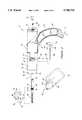
- FIG. 1is a schematic representation of the needleless injector with a medicine chamber filling mechanism attached thereto.
- FIG. 2is an exploded side view of the needleless injector.
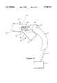
- FIG. 3Ais a plan view of the needleless injector with a schematic representation of an attached medicine chamber filling mechanism and spacer.
- FIG. 3Bis a partial plan view of the needleless injector with the fire button and activation valve in the fired position.
- FIG. 4is a side cross-section view of the needleless injector along line 4--4 in FIG. 3A.
- FIG. 5is a side cross-section view of the removable medicine chamber filling, mechanism.
- FIG. 6is a schematic representation of the needleless injector with an attached medicine chamber filling mechanism shown in two operative positions.
- the housing 16 of the needleless hypodermic injector assembly 10is connected to a low pressure air pump 12 or any other pressurized air source by an air hose 14.
- the hose 14may either be permanently attached to the housing 16, or attached to the housing 10 by a quick disconnect mechanism 15 within the housing's handle 18, thereby facilitating efficient attachment to the pump 12.
- the assembly 10utilizes low pressure air from the pump 12 to effectively administer a needleless injection to a patient.
- a spacer 26is movably carried by the filling mechanism 100, such that an air gap 28 is formed when the spacer 26 is positioned adjacent to the nozzle 24.
- an injector activating mechanismsuch as a "fire" button 30
- the low pressure air supplycauses a very narrow, highly focused stream of medicine to be ejected under high pressure through the nozzle 24, across the air gap 28, through an opening 25 in the spacer 26, and into an awaiting patient.
- the needleless hypodermic injector assembly 10incorporates several components.
- the hose 14releasably connects to the housing's handle 18.
- a second length of pressurized air hose 36extends through the handle 18 and connects, with a conventional hose connecting mechanism, to an air passage 38 within the main housing 16.
- the passage 38communicates with a valve insert 42 that contains an activation valve 44 and the fire button 30.
- a spring 46engages the fire button 30, thereby biasing the button 30 to a retracted ready position 48.
- the activation valve 44slides within the valve insert 42 to an open position, unblocks the air passage 38, and exposes an air port 50.
- the port 50is connected to an air chamber 54 formed by a cylinder 52 within the housing 16.
- An air piston 56serving as a driving piston, is slidably mounted within the pressurized air chamber 54, such that when the activation valve 44 is in the open position, the low pressure air rushes through the passage 38 and the port 50, and the air piston 56 is instantaneously driven forward within the air chamber 54.
- a sufficient sealis maintained between the air piston 56 and the surrounding cylinder 52 by an O-ring 58.
- a sufficient sealis maintained between the valve 44 and the insert 42 by an O-ring 45.
- a medicine delivery unit 62detachably mounts in the main housing 16 and comprises a cylindrical wall 65 having a circumferential shoulder on the outer forward end with an O-ring 114 therein, said wall defining a medicine chamber 64 with a medicine fill port 67 and a discharge piston 60.
- the nozzle 24is threaded into the outside of the forward end of the wall 65 and is in sealing engagement with O-ring 114. Alternatively, the nozzle 24 may simply be welded to wall 65 or insert molded in chamber 64.
- the piston 60has a piston head 78 and a rear rod extension 61 on which a biasing mechanism, such as a spring 66 is sleeved.
- the forward end of the springengages a fitting 68 that, in turn, is seated at the rear of the medicine chamber 64.
- the rod 61has an enlarged head 70 retaining the spring 66 and detachably engaging a recess 71 in the air piston 56.
- the piston 60has a discharge stroke within the medicine chamber 64 from a retracted start position 72, to a finished, discharge position 73 adjacent to the nozzle 24.
- the biasing spring 66automatically returns the piston 60 to the retracted position 72 after medicine has been delivered.
- the activation valve 44snaps to the open position, and low pressure air rushes into the air chamber 54.
- the air piston 56is instantaneously driven forward, thereby driving the discharge piston 60 through its discharge stroke within the medicine chamber 64.
- Any medicine contained within the medicine chamber 64is forced through an ejection orifice 74 in the nozzle 24.
- the piston head 78is sealed by its threaded cap bearing against O-ring 76. A close fit tolerance between the piston head and the wall 65 ensures all of the medicine within the medicine chamber 64 will be discharged during the discharge stroke.
- a quick disconnect mechanism 80installed in the housing's front end portion 81, secures the delivery unit 62 within the housing 16.
- the disconnect mechanism 80slidably mounts in the front end portion 81, and a spring 82 biases the disconnect mechanism 80 in a securing position.
- the delivery unithas a beveled nose 83 at the rear, so that as the delivery unit 62 is installed into the front of the main housing 16, the beveled nose 83 engages and pushes the disconnect mechanism 80 upward, thereby compressing the spring 82.
- the piston's footends in threaded cap 70 which engages the recess 71 in the drive piston 56, such that the biasing spring 66 is slightly compressed. Accordingly, when the quick disconnect mechanism 80 is depressed and the delivery unit 62 is released, the biasing spring 66 partially ejects the delivery unit 62 from the main housing 16.
- the housing 16 and handle 18are made of a durable and lightweight plastic, and the medicine delivery unit 62 is primarily made of stainless steel components.
- the entire steel delivery unit 62may be quickly ejected from the needleless hypodermic injector assembly 10, dropped into a sterilizing bath, and a new, sterile delivery unit may be inserted within the needleless hypodermic injector assembly 10. This sequence can be accomplished in a matter of seconds, and the assembly is ready for safe injections with the same or a different medicine.
- the inventionmakes possible a lightweight ergonomic design having a long useful life and providing economical, easily sterilizable use in rural clinics having few amenities.
- the fill port 67is located very close to the piston head 78 when the piston 60 is in its retracted position 72. Accordingly, the fill port 67 is positioned so as to be closed at the beginning of the piston's discharge stroke. Such positioning of the fill port 67 alleviates the requirement of a check valve to prevent medicine from flowing out of the fill port 67 during the discharge stroke.
- the fill port 67is a small orifice normally about 10 thousandths of an inch in diameter and about 10-20 thousandths of an inch long through which a medicine dose of approximately 0.5 ml is transferred into the medicine chamber.
- the needleless hypodermic injector assembly 10further includes a removable medicine chamber filling mechanism 100, which includes a medicine distributor 106 and a medicine vial holder 108, described in greater detail below, that engages the housing 16.
- a filling nozzle 104 on the filling mechanism 100is received by the housing 16 through a passage 102 located in the housing's front end 81.
- the passage 102coaxially aligns the nozzle 104 with the fill port 67 when delivery unit 62 has been properly installed. Accordingly, medicine may be transported into the medicine chamber 64 through the nozzle 104 and fill port 67 by using positive pressure to force the medicine into the medicine chamber 64.
- the delivery unit 62indicates when the filling mechanism 100 has completely filled the medicine chamber 64 when medicine begins to dribble through the nozzle's orifice 74.
- the filling mechanism 100 and spacer 26may be pivoted from a "ready to fire” position 110, with the spacer 26 in front of the nozzle 24, to a raised “filling position” 112 (FIG. 6, discussed in detail below), with the spacer 26 moved away from the nozzle 24.
- the medicine distributor 106is used to push medicine through the nozzle 104 and filling port 67 and into the medicine chamber 64.
- the spacer 26is integral to the removable filling mechanism 100, and when pivoted into the "ready to fire” position 110, the resulting air gap has a range from about 1.5 mm to 4.0 mm. The preferred size is about 3.5 mm.
- the spacer 26may be movably mounted to other structures of the needleless hypodermic injector assembly 10 and still achieve the goal of maintaining an air gap 28 between the nozzle 24 and the patient.
- the spacer 26has a small opening 25 through which the highly focused stream of medicine passes.
- an opening of about 4 mm.is preferred. This combination of gap distance and size of opening 25 have been found highly efficient in reducing splash-back, contact and capillary contamination of medicine and blood from contaminating the nozzle as compared to prior devices (such as a recessed nozzle orifice) which permit bunching of a patient's skin and otherwise do not adequately shield the nozzle and orifice from contamination.
- the needleless hypodermic injector assembly 10may be prohibited from firing by a safety mechanism 116.
- the safety 116includes a safety interlock 118 and a safety rod 120 within the housing 16.
- the safety interlock 118which has a foot 124 and a notch 122, engages the firing button 30.
- One end of the safety rod 120communicates with the notch 122, and the other end communicates with the medicine distributor 106.
- the safety interlock 118is pressed inward to the "safe" position 123 (FIG. 3A)
- the rod 120rests within the notch 122. In this position, the safety rod 120 does not extend into the medicine distributor 106 and interfere with the rotation of distributor 106.
- a camis provided in medicine distributor 106 by means of a slot 127 along an arc of distributor 106.
- the safety interlock 118When the safety interlock 118 is withdrawn to the "fire position" 125 (FIG. 3B), the safety rod 120 moves out of the notch 122 and extends into the slot 127, thereby interfering with the flat face of slot 127 (FIG. 3A) on the distributor 106. This interference prevents the filling mechanism 100 from being pivoted into the filling position 112.
- the safety interlock 118must be moved to the "safe" position 123.
- the safety interlock's foot 124is positioned within the housing 16, such that the foot 124 directly communicates with the activation valve 44.
- a fire button block 126prevents the button 30 from being depressed when the safety interlock 118 is in the safe position 123.
- the safety interlock's motion into and out of the main housing 16is limited by a pin 130 within slot 131 adjacent to the foot 124.
- the activation valve 44When the needleless hypodermic injector is ready to fire, as best seen in FIG. 3A, the activation valve 44 is closed, the low pressure air supply is blocked, and the air piston 56 and delivery piston 60 are at rest in the retracted position.
- a valve block 134 on the fire button 30fits into a notch 136 in the activation valve 44.
- the valve block 134moves forwardly out of the notch 136, thereby allowing the activation valve 44 to slide from the closed position to an open position, whereat the pressurized air moves from passage 38 to port 50.
- the pressurized air within the passage 38is sufficiently strong to instantaneously drive the activation valve 44 to the open position.
- the velocity or extent of force usedis independent of the speed in which said activating valve 44 will move to the open position. Once the valve block is no longer interfering with the activation valve 44, the valve will snap to the open position.
- the safety interlock 118After the needleless hypodermic injector has been fired, the safety interlock 118 must be returned to the "safe" position 123 in order to refill the medicine chamber 64. As the safety interlock 118 moves into the housing 16, the foot 124 engages the activation valve 44 and drives the valve 44 back to the closed position. In addition, the fire button's spring 46 forces the valve block 134 back into the notch 136 so as to prevent the valve 44 from sliding back to the open position.
- the safety interlockis interconnected with the filling mechanism 100 and the spacer 26, such that the safety interlock 118 may not be moved to the "fire position" until the spacer 26 has been moved to a particular predetermined orientation relative to the nozzle 24.
- the low pressure air from the pump 12has a pressure in the range of about 50 to 250 pounds per square inch (gauge) (psig). Good performance is achieved when the starting pressure is in the range of about 80 psig to 140 psig.
- the air pressure within the assembly 10drops, and after the injection, the pressurized air in the assembly 10 is in the range of about 60 psig to 100 psig.
- a preferred embodimentis to have an accumulator maintained at a base pressure of about 65-70 psig by a spring. A single stroke of an air pump raises this pressure to about 80 psig. After an injection, the pressure drops to the base pressure.
- the low pressure airdrives the pistons 56 and 60 forward, and the medicine within the medicine chamber 64 achieves a pressure in the range of about 2,500 psi to 4,500 psi as the fluid is forced through the nozzle's shaped orifice 74.
- the fluid streamhave either a coherent cylindrical configuration or a cone shape with the apex at or just beyond the outer side of opening 25.
- One way of producing the desired fluid stream shapeis to use a cylindrical orifice 74, optionally with the upstream edge created by a spherical counterbore.
- orifice 74has a diameter of about 6 thousandths of an inch and a length of about 15-18 thousandths of an inch.
- the resulting high pressure fluid streamhas a diameter ranging from about 0.004 inch to 0.008 inch, which is smaller than most hypodermic needles.
- This high pressure within the medicine chamber 64is generated by the low pressure air because of the relationship between the air piston's surface area and the discharge piston's surface area in the medicine chamber.
- the ratio between the surface areas utilizedranges from about 13:1 to 155:1.
- the preferred area ratiois about 64:1. It is to be noted that these ranges represent the design of the preferred embodiment, but the ranges are not to limit the scope of this patent.
- the low pressure air hose 14enters an on-board air chamber 40 that, in turn, connects to the air passage 38.
- the chamber 40holds enough pressurized air for the discharge assembly 10 to administer at least one injection.
- the hose 14can be removed, and the delivery assembly 10 may be transported away from the air source 12 to give an injection.
- the mobility of this embodimentallows for substantial flexibility in using the assembly 10.
- the removable filling mechanism 100includes a medicine vial holder 108 operatively connected to a medicine distributor 106.
- the medicine distributor 106utilizes positive pressure to distribute medicine from a vial 144 into the first medicine chamber 64.
- the vial holder 108has a vial receiving unit 146 with a clamping mechanism 148 that clamps the vial 144 into the receiving unit 146
- the clamp 148comprises a scissor-type clamp that engages the vial 144 around the vial's necked portion 150 adjacent to the vial's cap 152.
- the scissor clamp 148allows for different sized vials to be securely held within the receiving unit 146.
- the vial holder 108uses a medicine transport mechanism, such as a hollow needle 154, to pierce a membrane 156 on the vial 144 and gain access to the medicine therein.
- the medicineis drawn from the vial 144, through the hollow needle 154, through second filling port 162 and into a second medicine chamber 158 formed by a distributor housing 160.
- the medicineis prevented from flowing back into the vial 144 by a check valve 162 located between the second chamber 158 and the needle 154.
- the medicineis drawn into the second chamber 158 by withdrawing a plunger 164 that is slidably mounted in the chamber 158 while check valve 174 prevents the entrance of air through distributor orifice 170 from delivery unit 62.
- the plunger 164is used to generate positive pressure that drives the medicine through a channel 166 in the filler tube 168, and through the distributor orifice 170.
- medicineis prevented from flowing back through the distributor orifice 170 toward the vial 144 by a check valve 174 located at the beginning of the channel 166.
- the filler tube 168includes a filler nozzle 172 having a predetermined size allowing for efficient transfer of medicine from the filler nozzle 172 into the first medicine chamber 64 through the filler ports 102 and 67.
- a button operated pump diaphragmis substituted for plunger 164. A first depression of the button fills the chamber 158 and subsequent depressions provide the positive pressure that drives the medicine into the medicine chamber 64 and refills the chamber 158.
- the medicine chamber filling mechanism 100can pivot to the loading position 112 as the medicine delivery assembly 10 is oriented such that the vial 144 is coaxially aligned with the nozzle 24. When the assembly is pointed upward, the medicine in the vial 144 covers the needle 154. After a dose of medicine has been loaded into the first medicine chamber 64, and the filling mechanism 100 is pivoted back to the injecting position 110, the safety interlock 118 may be moved to the fire position 125, and the medicine delivery assembly is ready to deliver a dose of medicine upon depressing the fire button 30.
Landscapes
- Health & Medical Sciences (AREA)
- Vascular Medicine (AREA)
- Engineering & Computer Science (AREA)
- Anesthesiology (AREA)
- Biomedical Technology (AREA)
- Heart & Thoracic Surgery (AREA)
- Hematology (AREA)
- Life Sciences & Earth Sciences (AREA)
- Animal Behavior & Ethology (AREA)
- General Health & Medical Sciences (AREA)
- Public Health (AREA)
- Veterinary Medicine (AREA)
- Infusion, Injection, And Reservoir Apparatuses (AREA)
Abstract
Description
Claims (13)
Priority Applications (1)
| Application Number | Priority Date | Filing Date | Title |
|---|---|---|---|
| US08/483,192US5746714A (en) | 1993-04-05 | 1995-06-07 | Air powered needleless hypodermic injector |
Applications Claiming Priority (3)
| Application Number | Priority Date | Filing Date | Title |
|---|---|---|---|
| US4347693A | 1993-04-05 | 1993-04-05 | |
| US21503794A | 1994-03-18 | 1994-03-18 | |
| US08/483,192US5746714A (en) | 1993-04-05 | 1995-06-07 | Air powered needleless hypodermic injector |
Related Parent Applications (1)
| Application Number | Title | Priority Date | Filing Date |
|---|---|---|---|
| US21503794AContinuation-In-Part | 1993-04-05 | 1994-03-18 |
Publications (1)
| Publication Number | Publication Date |
|---|---|
| US5746714Atrue US5746714A (en) | 1998-05-05 |
Family
ID=26720466
Family Applications (1)
| Application Number | Title | Priority Date | Filing Date |
|---|---|---|---|
| US08/483,192Expired - Fee RelatedUS5746714A (en) | 1993-04-05 | 1995-06-07 | Air powered needleless hypodermic injector |
Country Status (1)
| Country | Link |
|---|---|
| US (1) | US5746714A (en) |
Cited By (51)
| Publication number | Priority date | Publication date | Assignee | Title |
|---|---|---|---|---|
| USD422697S (en)* | 1999-01-13 | 2000-04-11 | Powderject Research Limited | Hand held injector |
| US6099504A (en)* | 1997-10-22 | 2000-08-08 | Elan Corporation, Plc | Pre-filled injection delivery device |
| US6102896A (en)* | 1999-09-08 | 2000-08-15 | Cambridge Biostability Limited | Disposable injector device |
| US6312411B1 (en) | 1998-10-23 | 2001-11-06 | Aubex Corporation | Fluid supplying apparatus |
| US20020004639A1 (en)* | 2000-01-07 | 2002-01-10 | Willis John P. | Injection device |
| US6364866B1 (en)* | 1999-01-22 | 2002-04-02 | Douglas Furr | Syringe loading aid |
| US20020151842A1 (en)* | 2000-11-30 | 2002-10-17 | Gonnelli Robert R. | Injection systems |
| US6474369B2 (en)* | 1995-05-26 | 2002-11-05 | Penjet Corporation | Apparatus and method for delivering a lyophilized active with a needle-less injector |
| US20020183738A1 (en)* | 1999-06-02 | 2002-12-05 | Chee U. Hiram | Method and apparatus for treatment of atrial fibrillation |
| US20030009132A1 (en)* | 2001-04-13 | 2003-01-09 | Tricardia Llc | Syringe system |
| US20030013952A1 (en)* | 2001-03-12 | 2003-01-16 | Olympus Optical Co., Ltd. | Optical probe for producing tomogram of specimen by the use of low-coherence light |
| US20030088207A1 (en)* | 1999-11-23 | 2003-05-08 | Felton International, Inc. | Jet injector with hand piece |
| US6602222B1 (en) | 2000-10-13 | 2003-08-05 | Cambridge Biostability Ltd. | Disposable injection device |
| US6610042B2 (en)* | 1997-12-05 | 2003-08-26 | Felton Medical, Inc. | Disposable unit-dose jet-injection syringe for pre-filled and/or transfilled liquid injectable medical drug or vaccine products and method thereof |
| US6626871B1 (en) | 1999-10-11 | 2003-09-30 | Felton International, Inc. | Method and apparatus for removing cap from medical device |
| US6629958B1 (en) | 2000-06-07 | 2003-10-07 | Ronald P. Spinello | Leak sealing needle |
| US20040030320A1 (en)* | 1999-06-02 | 2004-02-12 | Boston Scientific Corporation | Devices and methods for delivering a drug |
| USD488862S1 (en) | 2002-06-04 | 2004-04-20 | Felton International, Inc. | Handpiece for jet injector |
| US20040111054A1 (en)* | 2002-06-04 | 2004-06-10 | Sergio Landau | High workload needle-free injection system |
| US6755220B2 (en) | 2001-04-27 | 2004-06-29 | Penjet Corporation | Method and apparatus for filling or refilling a needle-less injector |
| US6770054B1 (en) | 1999-11-23 | 2004-08-03 | Felton International, Inc. | Injector assembly with driving means and locking means |
| US20040159364A1 (en)* | 2003-02-19 | 2004-08-19 | Bioject Inc. | Needle-free injection system |
| US20040199106A1 (en)* | 2002-06-04 | 2004-10-07 | Sergio Landau | Needle-free injection system |
| US6824526B2 (en) | 2001-10-22 | 2004-11-30 | Penjet Corporation | Engine and diffuser for use with a needle-less injector |
| US20040249339A1 (en)* | 1998-12-18 | 2004-12-09 | Biovalve Technologies, Inc. | Injection devices |
| US20050192530A1 (en)* | 2001-04-13 | 2005-09-01 | Penjet Corporation | Method and apparatus for needle-less injection with a degassed fluid |
| US20050233287A1 (en)* | 2004-04-14 | 2005-10-20 | Vladimir Bulatov | Accessible computer system |
| US20060005844A1 (en)* | 2004-07-08 | 2006-01-12 | Coulter George G | Rolling tube apparatus and method for treating a wound |
| US7018356B2 (en) | 2002-10-31 | 2006-03-28 | Wise Roger R | Method and apparatus for adjusting the contents of a needle-less injector |
| US20060287631A1 (en)* | 1999-10-11 | 2006-12-21 | Leon Nathaniel J | Universal protector cap with auto-disable features for needle-free injectors |
| US20070055199A1 (en)* | 2005-08-10 | 2007-03-08 | Gilbert Scott J | Drug delivery device for buccal and aural applications and other areas of the body difficult to access |
| US20080071211A1 (en)* | 2006-09-19 | 2008-03-20 | Bioject Inc. | Needle-free injector and process for providing serial injections |
| WO2008045161A2 (en) | 2006-10-06 | 2008-04-17 | Bioject Inc. | Triggering mechanism for needle-free injector |
| US20080208114A1 (en)* | 2007-02-23 | 2008-08-28 | Sergio Landau | Needle-free injection devices and drug delivery systems therefor |
| US20080319383A1 (en)* | 2005-12-20 | 2008-12-25 | Antares Pharma, Inc. | Needle-Free Injection Device |
| US20100025503A1 (en)* | 2007-11-26 | 2010-02-04 | Bioject Inc. | Needle-free injection device with nozzle auto-disable |
| US20100076374A1 (en)* | 2007-11-26 | 2010-03-25 | Bioject Inc. | Injection device plunger auto-disable |
| US7717877B2 (en) | 2003-07-31 | 2010-05-18 | Sid Technologies, Llc | Injecting apparatus |
| US7887506B1 (en) | 1999-11-23 | 2011-02-15 | Pulse Needlefree Systems, Inc. | Safety mechanism to prevent accidental patient injection and methods of same |
| US8052645B2 (en) | 2008-07-23 | 2011-11-08 | Avant Medical Corp. | System and method for an injection using a syringe needle |
| US8177749B2 (en) | 2008-05-20 | 2012-05-15 | Avant Medical Corp. | Cassette for a hidden injection needle |
| US20150051574A1 (en)* | 2013-08-16 | 2015-02-19 | Gold Nanotech Inc. | Needleless Drug-Injecting System and Method Thereof |
| US9808579B2 (en) | 2013-05-08 | 2017-11-07 | Elwha Llc | Needleless injector systems, and related methods and components |
| US9974904B2 (en) | 2008-05-20 | 2018-05-22 | Avant Medical Corp. | Autoinjector system |
| US10092703B2 (en) | 2013-03-15 | 2018-10-09 | Amgen Inc. | Drug cassette, autoinjector, and autoinjector system |
| US10092706B2 (en) | 2011-04-20 | 2018-10-09 | Amgen Inc. | Autoinjector apparatus |
| US10492990B2 (en) | 2013-03-15 | 2019-12-03 | Amgen Inc. | Drug cassette, autoinjector, and autoinjector system |
| USD898908S1 (en) | 2012-04-20 | 2020-10-13 | Amgen Inc. | Pharmaceutical product cassette for an injection device |
| WO2021236092A1 (en)* | 2020-05-22 | 2021-11-25 | Pulse Needlefree Systems, Inc. | Injection device and components thereof |
| CN114917431A (en)* | 2022-05-17 | 2022-08-19 | 北京快舒尔医疗技术有限公司 | Syringe body and syringe having the same |
| WO2023205895A1 (en)* | 2022-04-29 | 2023-11-02 | Medical International Technologies (Mit Canada) Inc. | Vial adapter and injector assembly for a needle-free injector |
Citations (29)
| Publication number | Priority date | Publication date | Assignee | Title |
|---|---|---|---|---|
| US2821193A (en)* | 1952-07-22 | 1958-01-28 | Geoffrey W Walker | Multiple injection inoculator instrument |
| US3292622A (en)* | 1964-09-21 | 1966-12-20 | Oscar H Banker | Power operated inoculator |
| US3330276A (en)* | 1963-10-07 | 1967-07-11 | Scherer Corp R P | Hypodermic jet injector |
| US3330277A (en)* | 1964-08-17 | 1967-07-11 | Scherer Corp R P | Multidose hypodermic injector |
| FR1499582A (en)* | 1966-11-02 | 1967-10-27 | Needle-free injection device, especially for administering drug solutions | |
| US3462867A (en)* | 1967-11-13 | 1969-08-26 | Edward E Pinkman | Automobile visor mounted road map |
| US3518990A (en)* | 1968-05-02 | 1970-07-07 | Oscar H Banker | Gun type inoculator |
| US3526225A (en)* | 1967-03-31 | 1970-09-01 | Tokyo Sokuhan Kk | Jet-type hypodermic injection device |
| US3763859A (en)* | 1971-11-11 | 1973-10-09 | Pigmy Health Prod Inc | Injector apparatus |
| US3853125A (en)* | 1971-10-05 | 1974-12-10 | W Clark | Disposable needleless injector |
| US3859996A (en)* | 1973-07-18 | 1975-01-14 | Mizzy Inc | Multi-dose injector |
| US3908651A (en)* | 1974-05-17 | 1975-09-30 | Daystrol Scient Inc | Medicament injection device |
| US4103684A (en)* | 1976-12-30 | 1978-08-01 | Aaron Ismach | Hydraulically powered hypodermic injector with adapters for reducing and increasing fluid injection force |
| US4124024A (en)* | 1977-03-03 | 1978-11-07 | Schwebel Paul R | Disposable hypodermic injection ampule |
| US4266541A (en)* | 1978-09-19 | 1981-05-12 | Halen-Elliot Do Brazil Industria E Comercio Equipamentos De Precisao Ltda. | Pressure hypodermic injector for intermittent vaccination |
| US4342310A (en)* | 1980-07-08 | 1982-08-03 | Istvan Lindmayer | Hydro-pneumatic jet injector |
| US4403986A (en)* | 1981-04-16 | 1983-09-13 | Hoechst Aktiengesellschaft | Needle-less injection instrument |
| US4411650A (en)* | 1981-04-16 | 1983-10-25 | Hoechst Aktiengesellschaft | Piston pump for needle-less injection instruments |
| US4421508A (en)* | 1981-02-24 | 1983-12-20 | Cohen Edgar C | Vacuum-compression injector |
| EP0119286A1 (en)* | 1983-03-18 | 1984-09-26 | Internationales Forschungsinstitut für Reproduktionsmedizin und -biologie | Pressure-powered injection pistol |
| DE3328173A1 (en)* | 1982-05-27 | 1985-02-14 | Preci-Tech Ltd., Ville St. Laurent, Quebec | NEEDLE-FREE HYPODERMATIC INJECTOR |
| EP0133471A1 (en)* | 1983-06-29 | 1985-02-27 | "FEG" Fegyver- és Gázkészülékgyár | Needle-free injection device, e.g. for injecting insulin |
| US4560377A (en)* | 1983-01-24 | 1985-12-24 | Sicim Spa | Endermic injector device |
| US4592742A (en)* | 1984-08-28 | 1986-06-03 | Sergio Landau | Pressure hypodermic syringe |
| US4596556A (en)* | 1985-03-25 | 1986-06-24 | Bioject, Inc. | Hypodermic injection apparatus |
| FR2630010A1 (en)* | 1988-04-19 | 1989-10-20 | Bearn Mecanique Aviat Sa | Needleless injection apparatus, in particular for the simultaneous injection of at least two separate products |
| US5049125A (en)* | 1987-05-26 | 1991-09-17 | Claude Accaries | Needleless injection apparatus of a liquid, notably for dental care |
| US5064413A (en)* | 1989-11-09 | 1991-11-12 | Bioject, Inc. | Needleless hypodermic injection device |
| US5256142A (en)* | 1991-08-06 | 1993-10-26 | Sicim Spa | Injector administering subcutaneous injections without a needle and with a one-shot cap |
- 1995
- 1995-06-07USUS08/483,192patent/US5746714A/ennot_activeExpired - Fee Related
Patent Citations (31)
| Publication number | Priority date | Publication date | Assignee | Title |
|---|---|---|---|---|
| US2821193A (en)* | 1952-07-22 | 1958-01-28 | Geoffrey W Walker | Multiple injection inoculator instrument |
| US3330276A (en)* | 1963-10-07 | 1967-07-11 | Scherer Corp R P | Hypodermic jet injector |
| US3330277A (en)* | 1964-08-17 | 1967-07-11 | Scherer Corp R P | Multidose hypodermic injector |
| US3292622A (en)* | 1964-09-21 | 1966-12-20 | Oscar H Banker | Power operated inoculator |
| FR1499582A (en)* | 1966-11-02 | 1967-10-27 | Needle-free injection device, especially for administering drug solutions | |
| US3526225A (en)* | 1967-03-31 | 1970-09-01 | Tokyo Sokuhan Kk | Jet-type hypodermic injection device |
| US3462867A (en)* | 1967-11-13 | 1969-08-26 | Edward E Pinkman | Automobile visor mounted road map |
| US3518990A (en)* | 1968-05-02 | 1970-07-07 | Oscar H Banker | Gun type inoculator |
| US3853125A (en)* | 1971-10-05 | 1974-12-10 | W Clark | Disposable needleless injector |
| US3763859A (en)* | 1971-11-11 | 1973-10-09 | Pigmy Health Prod Inc | Injector apparatus |
| US3859996A (en)* | 1973-07-18 | 1975-01-14 | Mizzy Inc | Multi-dose injector |
| US3908651A (en)* | 1974-05-17 | 1975-09-30 | Daystrol Scient Inc | Medicament injection device |
| US4103684A (en)* | 1976-12-30 | 1978-08-01 | Aaron Ismach | Hydraulically powered hypodermic injector with adapters for reducing and increasing fluid injection force |
| US4124024A (en)* | 1977-03-03 | 1978-11-07 | Schwebel Paul R | Disposable hypodermic injection ampule |
| US4266541A (en)* | 1978-09-19 | 1981-05-12 | Halen-Elliot Do Brazil Industria E Comercio Equipamentos De Precisao Ltda. | Pressure hypodermic injector for intermittent vaccination |
| US4342310A (en)* | 1980-07-08 | 1982-08-03 | Istvan Lindmayer | Hydro-pneumatic jet injector |
| US4421508A (en)* | 1981-02-24 | 1983-12-20 | Cohen Edgar C | Vacuum-compression injector |
| US4403986A (en)* | 1981-04-16 | 1983-09-13 | Hoechst Aktiengesellschaft | Needle-less injection instrument |
| US4411650A (en)* | 1981-04-16 | 1983-10-25 | Hoechst Aktiengesellschaft | Piston pump for needle-less injection instruments |
| US4623332A (en)* | 1982-05-27 | 1986-11-18 | Patents Unlimited Ltd. | Needleless jet injector |
| DE3328173A1 (en)* | 1982-05-27 | 1985-02-14 | Preci-Tech Ltd., Ville St. Laurent, Quebec | NEEDLE-FREE HYPODERMATIC INJECTOR |
| US4560377A (en)* | 1983-01-24 | 1985-12-24 | Sicim Spa | Endermic injector device |
| EP0119286A1 (en)* | 1983-03-18 | 1984-09-26 | Internationales Forschungsinstitut für Reproduktionsmedizin und -biologie | Pressure-powered injection pistol |
| EP0133471A1 (en)* | 1983-06-29 | 1985-02-27 | "FEG" Fegyver- és Gázkészülékgyár | Needle-free injection device, e.g. for injecting insulin |
| US4626242A (en)* | 1983-06-29 | 1986-12-02 | Radelkis Elektrokemiai Muszergyarto Ipari Szovetkezet | Siphon-cartridge activated automatic inoculating device wihtout needle for individual acculation, e.g. for insulinization |
| US4592742A (en)* | 1984-08-28 | 1986-06-03 | Sergio Landau | Pressure hypodermic syringe |
| US4596556A (en)* | 1985-03-25 | 1986-06-24 | Bioject, Inc. | Hypodermic injection apparatus |
| US5049125A (en)* | 1987-05-26 | 1991-09-17 | Claude Accaries | Needleless injection apparatus of a liquid, notably for dental care |
| FR2630010A1 (en)* | 1988-04-19 | 1989-10-20 | Bearn Mecanique Aviat Sa | Needleless injection apparatus, in particular for the simultaneous injection of at least two separate products |
| US5064413A (en)* | 1989-11-09 | 1991-11-12 | Bioject, Inc. | Needleless hypodermic injection device |
| US5256142A (en)* | 1991-08-06 | 1993-10-26 | Sicim Spa | Injector administering subcutaneous injections without a needle and with a one-shot cap |
Cited By (103)
| Publication number | Priority date | Publication date | Assignee | Title |
|---|---|---|---|---|
| US6474369B2 (en)* | 1995-05-26 | 2002-11-05 | Penjet Corporation | Apparatus and method for delivering a lyophilized active with a needle-less injector |
| US6830560B1 (en) | 1997-10-22 | 2004-12-14 | Elan Corporation Plc | Automatic syringe |
| US6099504A (en)* | 1997-10-22 | 2000-08-08 | Elan Corporation, Plc | Pre-filled injection delivery device |
| US6610042B2 (en)* | 1997-12-05 | 2003-08-26 | Felton Medical, Inc. | Disposable unit-dose jet-injection syringe for pre-filled and/or transfilled liquid injectable medical drug or vaccine products and method thereof |
| US6312411B1 (en) | 1998-10-23 | 2001-11-06 | Aubex Corporation | Fluid supplying apparatus |
| US20050154350A1 (en)* | 1998-12-18 | 2005-07-14 | Biovalve Technologies, Inc. | Injection devices |
| US20040249339A1 (en)* | 1998-12-18 | 2004-12-09 | Biovalve Technologies, Inc. | Injection devices |
| US6960184B2 (en) | 1998-12-18 | 2005-11-01 | Biovalve Technologies, Inc. | Injection devices |
| US7740607B2 (en) | 1998-12-18 | 2010-06-22 | Valeritas, Inc. | Modular units for use in an injection device |
| USD422697S (en)* | 1999-01-13 | 2000-04-11 | Powderject Research Limited | Hand held injector |
| US6364866B1 (en)* | 1999-01-22 | 2002-04-02 | Douglas Furr | Syringe loading aid |
| US20070055230A1 (en)* | 1999-06-02 | 2007-03-08 | Scimed Life Systems, Inc | Methods of treating cardiac arrhythmia |
| US20020183738A1 (en)* | 1999-06-02 | 2002-12-05 | Chee U. Hiram | Method and apparatus for treatment of atrial fibrillation |
| US20040030320A1 (en)* | 1999-06-02 | 2004-02-12 | Boston Scientific Corporation | Devices and methods for delivering a drug |
| US6102896A (en)* | 1999-09-08 | 2000-08-15 | Cambridge Biostability Limited | Disposable injector device |
| US6626871B1 (en) | 1999-10-11 | 2003-09-30 | Felton International, Inc. | Method and apparatus for removing cap from medical device |
| US6802826B1 (en) | 1999-10-11 | 2004-10-12 | Felton International, Inc. | Universal anti-infectious protector for needleless injectors |
| US20060287631A1 (en)* | 1999-10-11 | 2006-12-21 | Leon Nathaniel J | Universal protector cap with auto-disable features for needle-free injectors |
| US20030088207A1 (en)* | 1999-11-23 | 2003-05-08 | Felton International, Inc. | Jet injector with hand piece |
| US7029457B2 (en) | 1999-11-23 | 2006-04-18 | Felton International, Inc. | Jet injector with hand piece |
| US7887506B1 (en) | 1999-11-23 | 2011-02-15 | Pulse Needlefree Systems, Inc. | Safety mechanism to prevent accidental patient injection and methods of same |
| US6770054B1 (en) | 1999-11-23 | 2004-08-03 | Felton International, Inc. | Injector assembly with driving means and locking means |
| US7806867B2 (en) | 2000-01-07 | 2010-10-05 | Valeritas, Inc. | Injection device |
| US20020004639A1 (en)* | 2000-01-07 | 2002-01-10 | Willis John P. | Injection device |
| US20040220525A1 (en)* | 2000-01-07 | 2004-11-04 | Willis John P | Injection device |
| US6629958B1 (en) | 2000-06-07 | 2003-10-07 | Ronald P. Spinello | Leak sealing needle |
| US6602222B1 (en) | 2000-10-13 | 2003-08-05 | Cambridge Biostability Ltd. | Disposable injection device |
| US20030149397A9 (en)* | 2000-11-30 | 2003-08-07 | Gonnelli Robert R. | Injection systems |
| US20020151842A1 (en)* | 2000-11-30 | 2002-10-17 | Gonnelli Robert R. | Injection systems |
| US20020156418A1 (en)* | 2000-11-30 | 2002-10-24 | Gonnelli Robert R. | Injection systems |
| US7931614B2 (en) | 2000-11-30 | 2011-04-26 | Valeritas, Inc. | Injection systems |
| US20110172634A1 (en)* | 2000-11-30 | 2011-07-14 | Valeritas, Inc. | Injection systems |
| US8500681B2 (en) | 2000-11-30 | 2013-08-06 | Valeritas, Inc. | Injection systems |
| US20020161329A1 (en)* | 2000-11-30 | 2002-10-31 | Gonnelli Robert R. | Injection systems |
| US7150409B2 (en) | 2000-11-30 | 2006-12-19 | Biovalve Technologies, Inc. | Injection systems |
| US20030013952A1 (en)* | 2001-03-12 | 2003-01-16 | Olympus Optical Co., Ltd. | Optical probe for producing tomogram of specimen by the use of low-coherence light |
| US20050197633A1 (en)* | 2001-04-13 | 2005-09-08 | Schwartz Robert S. | Syringe system |
| US20050192530A1 (en)* | 2001-04-13 | 2005-09-01 | Penjet Corporation | Method and apparatus for needle-less injection with a degassed fluid |
| US6969373B2 (en) | 2001-04-13 | 2005-11-29 | Tricardia, Llc | Syringe system |
| WO2002083228A3 (en)* | 2001-04-13 | 2003-04-10 | Tricardia Llc | Syringe system |
| US20030009132A1 (en)* | 2001-04-13 | 2003-01-09 | Tricardia Llc | Syringe system |
| US6755220B2 (en) | 2001-04-27 | 2004-06-29 | Penjet Corporation | Method and apparatus for filling or refilling a needle-less injector |
| US6824526B2 (en) | 2001-10-22 | 2004-11-30 | Penjet Corporation | Engine and diffuser for use with a needle-less injector |
| US7238167B2 (en) | 2002-06-04 | 2007-07-03 | Bioject Inc. | Needle-free injection system |
| USD488862S1 (en) | 2002-06-04 | 2004-04-20 | Felton International, Inc. | Handpiece for jet injector |
| US20040199106A1 (en)* | 2002-06-04 | 2004-10-07 | Sergio Landau | Needle-free injection system |
| US7156823B2 (en) | 2002-06-04 | 2007-01-02 | Bioject Inc. | High workload needle-free injection system |
| US20040111054A1 (en)* | 2002-06-04 | 2004-06-10 | Sergio Landau | High workload needle-free injection system |
| US7018356B2 (en) | 2002-10-31 | 2006-03-28 | Wise Roger R | Method and apparatus for adjusting the contents of a needle-less injector |
| US20040159364A1 (en)* | 2003-02-19 | 2004-08-19 | Bioject Inc. | Needle-free injection system |
| US6935384B2 (en) | 2003-02-19 | 2005-08-30 | Bioject Inc. | Needle-free injection system |
| US7717877B2 (en) | 2003-07-31 | 2010-05-18 | Sid Technologies, Llc | Injecting apparatus |
| US20050233287A1 (en)* | 2004-04-14 | 2005-10-20 | Vladimir Bulatov | Accessible computer system |
| US20060005844A1 (en)* | 2004-07-08 | 2006-01-12 | Coulter George G | Rolling tube apparatus and method for treating a wound |
| US20070055200A1 (en)* | 2005-08-10 | 2007-03-08 | Gilbert Scott J | Needle-free jet injection drug delivery device |
| US8591457B2 (en) | 2005-08-10 | 2013-11-26 | Alza Corporation | Method for making a needle-free jet injection drug delivery device |
| US8998881B2 (en) | 2005-08-10 | 2015-04-07 | Alza Corporation | Method for delivering drugs to tissue under microjet propulsion |
| US20070055214A1 (en)* | 2005-08-10 | 2007-03-08 | Gilbert Scott J | Method for delivering drugs to tissue under microjet propulsion |
| US20070055199A1 (en)* | 2005-08-10 | 2007-03-08 | Gilbert Scott J | Drug delivery device for buccal and aural applications and other areas of the body difficult to access |
| US7988660B2 (en) | 2005-12-20 | 2011-08-02 | Eli Lilly And Company | Needle-free injection device |
| US20080319383A1 (en)* | 2005-12-20 | 2008-12-25 | Antares Pharma, Inc. | Needle-Free Injection Device |
| US20080071211A1 (en)* | 2006-09-19 | 2008-03-20 | Bioject Inc. | Needle-free injector and process for providing serial injections |
| US7942845B2 (en) | 2006-09-19 | 2011-05-17 | Bioject, Inc. | Needle-free injector and process for providing serial injections |
| US7547293B2 (en) | 2006-10-06 | 2009-06-16 | Bioject, Inc. | Triggering mechanism for needle-free injector |
| US20090247940A1 (en)* | 2006-10-06 | 2009-10-01 | Bioject, Inc. | Triggering mechanism for a needle-free injector |
| US8105272B2 (en) | 2006-10-06 | 2012-01-31 | Bioject, Inc. | Triggering mechanism for a needle-free injector |
| WO2008045161A2 (en) | 2006-10-06 | 2008-04-17 | Bioject Inc. | Triggering mechanism for needle-free injector |
| US7744563B2 (en) | 2007-02-23 | 2010-06-29 | Bioject, Inc. | Needle-free injection devices and drug delivery systems therefor |
| US20080208114A1 (en)* | 2007-02-23 | 2008-08-28 | Sergio Landau | Needle-free injection devices and drug delivery systems therefor |
| US8617099B2 (en) | 2007-11-26 | 2013-12-31 | Bioject Inc. | Injection device plunger auto-disable |
| US20100025503A1 (en)* | 2007-11-26 | 2010-02-04 | Bioject Inc. | Needle-free injection device with nozzle auto-disable |
| US20100076374A1 (en)* | 2007-11-26 | 2010-03-25 | Bioject Inc. | Injection device plunger auto-disable |
| US10792426B2 (en) | 2008-05-20 | 2020-10-06 | Avant Medical Corp. | Autoinjector system |
| US10864324B2 (en) | 2008-05-20 | 2020-12-15 | Avant Medical Corp. | Autoinjector system |
| US11883633B2 (en) | 2008-05-20 | 2024-01-30 | Avant Medical Corp. | Autoinjector system |
| US8177749B2 (en) | 2008-05-20 | 2012-05-15 | Avant Medical Corp. | Cassette for a hidden injection needle |
| US9974904B2 (en) | 2008-05-20 | 2018-05-22 | Avant Medical Corp. | Autoinjector system |
| US9925336B2 (en) | 2008-05-20 | 2018-03-27 | Avant Medical Corp. | Cassette for a hidden injection needle |
| US8052645B2 (en) | 2008-07-23 | 2011-11-08 | Avant Medical Corp. | System and method for an injection using a syringe needle |
| US9616173B2 (en) | 2008-07-23 | 2017-04-11 | Avant Medical Corporation | System and method for an injection using a syringe needle |
| US11724032B2 (en) | 2008-07-23 | 2023-08-15 | Avant Medical Corp. | System and method for an injection using a syringe needle |
| US12186535B2 (en) | 2008-07-23 | 2025-01-07 | Avant Medical Corp. | System and method for an injection using a syringe needle |
| US10639422B2 (en) | 2008-07-23 | 2020-05-05 | Avant Medical Corp. | System and method for an injection using a syringe needle |
| US10092706B2 (en) | 2011-04-20 | 2018-10-09 | Amgen Inc. | Autoinjector apparatus |
| US12350480B2 (en) | 2011-04-20 | 2025-07-08 | Amgen Inc. | Autoinjector apparatus |
| US11986643B2 (en) | 2011-04-20 | 2024-05-21 | Amgen Inc. | Autoinjector apparatus |
| US11419990B2 (en) | 2011-04-20 | 2022-08-23 | Amgen Inc. | Autoinjector apparatus |
| US10918805B2 (en) | 2011-04-20 | 2021-02-16 | Amgen Inc. | Autoinjector apparatus |
| USD1076075S1 (en) | 2012-04-20 | 2025-05-20 | Amgen Inc. | Pharmaceutical product cassette for an injection device |
| USD898908S1 (en) | 2012-04-20 | 2020-10-13 | Amgen Inc. | Pharmaceutical product cassette for an injection device |
| US10492990B2 (en) | 2013-03-15 | 2019-12-03 | Amgen Inc. | Drug cassette, autoinjector, and autoinjector system |
| US11020537B2 (en) | 2013-03-15 | 2021-06-01 | Amgen Inc. | Drug cassette, autoinjector, and autoinjector system |
| US10092703B2 (en) | 2013-03-15 | 2018-10-09 | Amgen Inc. | Drug cassette, autoinjector, and autoinjector system |
| US11944798B2 (en) | 2013-03-15 | 2024-04-02 | Amgen Inc. | Drug cassette, autoinjector, and autoinjector system |
| US10786629B2 (en) | 2013-03-15 | 2020-09-29 | Amgen Inc. | Drug cassette, autoinjector, and autoinjector system |
| US9808579B2 (en) | 2013-05-08 | 2017-11-07 | Elwha Llc | Needleless injector systems, and related methods and components |
| US9457151B2 (en)* | 2013-08-16 | 2016-10-04 | Gold Nanotech Inc. | Needleless drug-injecting system and method thereof |
| CN104368067A (en)* | 2013-08-16 | 2015-02-25 | 京华堂实业股份有限公司 | Needleless injection system and injection method thereof |
| US20150051574A1 (en)* | 2013-08-16 | 2015-02-19 | Gold Nanotech Inc. | Needleless Drug-Injecting System and Method Thereof |
| WO2021236092A1 (en)* | 2020-05-22 | 2021-11-25 | Pulse Needlefree Systems, Inc. | Injection device and components thereof |
| CN115666686A (en)* | 2020-05-22 | 2023-01-31 | 脉冲无针系统股份有限公司 | Injection device and components thereof |
| WO2023205895A1 (en)* | 2022-04-29 | 2023-11-02 | Medical International Technologies (Mit Canada) Inc. | Vial adapter and injector assembly for a needle-free injector |
| CN114917431A (en)* | 2022-05-17 | 2022-08-19 | 北京快舒尔医疗技术有限公司 | Syringe body and syringe having the same |
Similar Documents
| Publication | Publication Date | Title |
|---|---|---|
| US5746714A (en) | Air powered needleless hypodermic injector | |
| US7029457B2 (en) | Jet injector with hand piece | |
| RU2179864C2 (en) | Needleless injector | |
| US4447225A (en) | Multidose jet injector | |
| US6506177B2 (en) | Needle-less injection system | |
| JP3257794B2 (en) | Needleless syringe | |
| US6939319B1 (en) | Process and device for single use, needle-free intradermal, subcutaneous, or intramuscular injections | |
| US7618393B2 (en) | Needle-less injector and method of fluid delivery | |
| US6689095B1 (en) | Needleless permanent makeup and tattoo device | |
| JP3213008B2 (en) | Jet hypodermic injection device | |
| US4874367A (en) | Hypodermic jet injector and cartridge therefor | |
| US6264637B1 (en) | Marking syringe | |
| JP4299466B2 (en) | Needle-assisted jet injector | |
| US20040158195A1 (en) | Needle-free mass injection device | |
| US5073165A (en) | Hypodermic jet injector and cartridge therefor | |
| US20090118738A1 (en) | Needless applicator system and method for application of medicament to the back of an eye | |
| US20050192530A1 (en) | Method and apparatus for needle-less injection with a degassed fluid | |
| KR101397129B1 (en) | Medication injection device | |
| AU2002336381A1 (en) | Apparatus for needle-less injection with a degassed fluid | |
| JP4658957B2 (en) | Impact chamber for jet feeder | |
| WO1995025555A1 (en) | Air-powered needleless hypodermic injector | |
| WO2007146266A1 (en) | A vial system and method for needle-less injector | |
| CA2463407C (en) | Jet injector with hand piece | |
| KR20250052872A (en) | Head for handpiece and liquid jet injection device having the same | |
| WO1998041250A2 (en) | Needleless injector and holder therefor |
Legal Events
| Date | Code | Title | Description |
|---|---|---|---|
| AS | Assignment | Owner name:P.A.T.H., WASHINGTON Free format text:ASSIGNMENT OF ASSIGNORS INTEREST;ASSIGNORS:SALO, TIMOTHY J.;AUSTIN, GLENN D.;LENNON, T. PATRICK;REEL/FRAME:007650/0102;SIGNING DATES FROM 19950816 TO 19950817 | |
| AS | Assignment | Owner name:VITAJET CORPORATION, CALIFORNIA Free format text:ASSIGNMENT OF ASSIGNORS INTEREST;ASSIGNOR:LANDAU, SERGIO;REEL/FRAME:007658/0077 Effective date:19950912 | |
| FEPP | Fee payment procedure | Free format text:PAYOR NUMBER ASSIGNED (ORIGINAL EVENT CODE: ASPN); ENTITY STATUS OF PATENT OWNER: SMALL ENTITY | |
| FPAY | Fee payment | Year of fee payment:4 | |
| REMI | Maintenance fee reminder mailed | ||
| FPAY | Fee payment | Year of fee payment:8 | |
| AS | Assignment | Owner name:BIOJECT INC., OREGON Free format text:ASSIGNMENT OF ASSIGNORS INTEREST;ASSIGNOR:PROGRAM FOR APPROPRIATE TECHNOLOGY IN HEALTH;REEL/FRAME:017649/0514 Effective date:20050929 | |
| AS | Assignment | Owner name:PARTNERS FOR GROWTH, L.P.,CALIFORNIA Free format text:SECURITY AGREEMENT;ASSIGNOR:BIOJECT, INC.;REEL/FRAME:018606/0671 Effective date:20061211 Owner name:PARTNERS FOR GROWTH, L.P., CALIFORNIA Free format text:SECURITY AGREEMENT;ASSIGNOR:BIOJECT, INC.;REEL/FRAME:018606/0671 Effective date:20061211 | |
| AS | Assignment | Owner name:PARTNERS FOR GROWTH, L.P., CALIFORNIA Free format text:SECURITY AGREEMENT;ASSIGNOR:BIOJECT, INC.;REEL/FRAME:019773/0642 Effective date:20070831 Owner name:PARTNERS FOR GROWTH, L.P.,CALIFORNIA Free format text:SECURITY AGREEMENT;ASSIGNOR:BIOJECT, INC.;REEL/FRAME:019773/0642 Effective date:20070831 | |
| REMI | Maintenance fee reminder mailed | ||
| LAPS | Lapse for failure to pay maintenance fees | ||
| STCH | Information on status: patent discontinuation | Free format text:PATENT EXPIRED DUE TO NONPAYMENT OF MAINTENANCE FEES UNDER 37 CFR 1.362 | |
| FP | Lapsed due to failure to pay maintenance fee | Effective date:20100505 |