US5746480A - Armrest assembly - Google Patents
Armrest assemblyDownload PDFInfo
- Publication number
- US5746480A US5746480AUS08/289,300US28930094AUS5746480AUS 5746480 AUS5746480 AUS 5746480AUS 28930094 AUS28930094 AUS 28930094AUS 5746480 AUS5746480 AUS 5746480A
- Authority
- US
- United States
- Prior art keywords
- support member
- armrest
- tubular support
- chair
- piece
- Prior art date
- Legal status (The legal status is an assumption and is not a legal conclusion. Google has not performed a legal analysis and makes no representation as to the accuracy of the status listed.)
- Expired - Lifetime
Links
Images


Classifications
- A—HUMAN NECESSITIES
- A47—FURNITURE; DOMESTIC ARTICLES OR APPLIANCES; COFFEE MILLS; SPICE MILLS; SUCTION CLEANERS IN GENERAL
- A47C—CHAIRS; SOFAS; BEDS
- A47C1/00—Chairs adapted for special purposes
- A47C1/02—Reclining or easy chairs
- A47C1/022—Reclining or easy chairs having independently-adjustable supporting parts
- A47C1/03—Reclining or easy chairs having independently-adjustable supporting parts the parts being arm-rests
- A—HUMAN NECESSITIES
- A47—FURNITURE; DOMESTIC ARTICLES OR APPLIANCES; COFFEE MILLS; SPICE MILLS; SUCTION CLEANERS IN GENERAL
- A47B—TABLES; DESKS; OFFICE FURNITURE; CABINETS; DRAWERS; GENERAL DETAILS OF FURNITURE
- A47B21/00—Tables or desks for office equipment, e.g. typewriters, keyboards
- A47B21/03—Tables or desks for office equipment, e.g. typewriters, keyboards with substantially horizontally extensible or adjustable parts other than drawers, e.g. leaves
- A47B21/0371—Platforms for supporting wrists
- A—HUMAN NECESSITIES
- A47—FURNITURE; DOMESTIC ARTICLES OR APPLIANCES; COFFEE MILLS; SPICE MILLS; SUCTION CLEANERS IN GENERAL
- A47C—CHAIRS; SOFAS; BEDS
- A47C16/00—Stand-alone rests or supports for feet, legs, arms, back or head
- A—HUMAN NECESSITIES
- A47—FURNITURE; DOMESTIC ARTICLES OR APPLIANCES; COFFEE MILLS; SPICE MILLS; SUCTION CLEANERS IN GENERAL
- A47C—CHAIRS; SOFAS; BEDS
- A47C7/00—Parts, details, or accessories of chairs or stools
- A47C7/54—Supports for the arms
- A47C7/546—Supports for the arms of detachable type
- A—HUMAN NECESSITIES
- A47—FURNITURE; DOMESTIC ARTICLES OR APPLIANCES; COFFEE MILLS; SPICE MILLS; SUCTION CLEANERS IN GENERAL
- A47B—TABLES; DESKS; OFFICE FURNITURE; CABINETS; DRAWERS; GENERAL DETAILS OF FURNITURE
- A47B2200/00—General construction of tables or desks
- A47B2200/0084—Accessories for tables or desks
- A47B2200/0092—Articulated arm used as wrist support
Definitions
- the present inventionrelates to an armrest assembly for attachment to a chair.
- a chair, or an armrest assemblyfor attachment to a chair, which (i) properly supports the weight of the arm of a person sitting in the chair, (ii) at the correct location, which may be adjustable, and (iii) allows for full movement of the person's hand through the desired range of motion without losing the support of the armrest.
- Such an armrest assemblyshould preferably be easily attachable to many different chairs without substantial modification.
- the present inventionrelates to an armrest assembly for attachment to a chair or other type of work station such as a bench, desk, or table.
- the armrest assemblyincludes a base plate adapted to be secured intermediate the pedestal assembly and the seat bottom cushion of a typical office chair, with the fasteners which secure the pedestal assembly to the seat bottom cushion extending through fastener openings in the base plate.
- the base platepreferably has at least two sets of fastener openings arranged in different patterns, whereby the base plate can selectively be secured intermediate the pedestal assembly and the seat bottom cushion of at least two different chairs having different fastener patterns.
- one armrest assemblyis easily attachable to a number of different chairs without structural change to any of the chairs.
- the armrestitself slides relative to the armrest support. This provides for an additional degree of movement for the arm. Specifically, it allows the hand to move laterally (for example, along a keyboard) without lifting off from the armrest or sliding along the armrest. If the arm only pivots, by virtue of the pivotal movement provided by two pivot joints in the armrest, the hand travels in a circular arc with the armrest as the center of rotation. In this case, the hand, for example, can not follow the home row of keys on the keyboard as it moves left to right. However, with the sliding motion provided by the present invention, the hand can move forward and backward as well as pivot. This compensates for the arcuate motion provided by a pivot joint, and allows the hand to travel as desired by the operator.
- the armrest assemblyincludes joint means responsive to downward force on the armrest from the person's arm to restrict movement of the armrest relative to the base.
- Pressurei.e., weight of the arm or gravity
- the joint meansmay be constructed by selection of materials to provide free movement when desired and restriction of movement when desired.
- the armrest slideis preferably self-centering in its sliding motion.
- the armrestis preferably pivotal about the armrest support member through a range of motion of 360°, with detent stops generally limiting the pivoting motion to a range of about 90°.
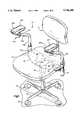
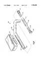
- FIG. 1is a front left perspective view of a chair having attached to it an armrest assembly in accordance with the present invention, with the armrest itself not shown;
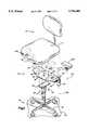
- FIG. 2is a partially exploded view of the chair and armrest assembly of FIG. 1;
- FIG. 3is an enlarged view of a lower portion of the armrest assembly of FIG. 1;
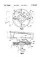
- FIG. 4is a sectional view of a lower portion of the armrest assembly of FIG. 1;
- FIG. 5is a sectional view taken along line 5--5 of FIG. 4;
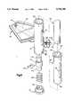
- FIG. 6is an enlarged exploded view of a lower portion of the armrest assembly of FIG. 1;
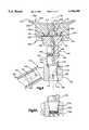
- FIG. 7is an enlarged exploded view of an upper portion of the armrest assembly of FIG. 1, with the armrest itself not shown;
- FIG. 8is a sectional view of the an upper portion of the armrest assembly of FIG. 1, showing the armrest itself;
- FIG. 8Ais a view of an alternate support post construction
- FIG. 9is a schematic view illustrating the sliding movement of the armrest
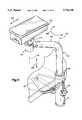
- FIG. 10is a schematic top plan view of the chair and armrest assembly of FIG. 1 illustrating the various degrees of movement of the armrest;
- FIG. 11is a schematic exploded view of a second embodiment of the armrest assembly of the present invention.
- FIG. 12is a top plan view of portions of a third embodiment of the armrest assembly of the present invention.
- FIG. 13is a schematic sectional view of the armrest assembly of FIG. 12.
- FIG. 14is a perspective view illustrating the various axes of movement of the armrest assembly.
- the present inventionrelates to an armrest assembly for attachment to a work station such as a chair or the like.
- the present inventionis applicable to various armrest assembly constructions.
- the present inventionis illustrated in FIG. 1 as applied to an armrest assembly 10 for use with a known chair 12.
- the chair 12is of the type including a seat bottom cushion 14 on which a person can sit.
- a pedestal assembly 16has a lower portion 18 engageable with a floor 20 and an upper portion 22 connected with the seat bottom cushion 14.
- a plurality of fasteners 24extend between the pedestal assembly upper portion 22 and the seat bottom cushion 14. The fasteners 24 secure the pedestal assembly upper portion 22 to the underside of the seat bottom cushion 14 to support the seat bottom cushion off the floor 18.
- the fasteners 24are spaced apart from each other and arranged in a particular pattern unique to that chair. Other chairs of the same type, from different manufacturers or different models from the same manufacturer, will have different fastener patterns.
- the armrest assembly 10includes a base plate 30.
- the base plate 30is a planar piece of steel which is sized to fit the underside of a chair seat bottom cushion, typically, about 10 ⁇ 16 inches.
- the base plate 30has an upper major side surface 32 and a lower major side surface 34.
- the base platecan be curved to fit a curved seat bottom cushion, if necessary.
- the base plate 30has a first set of fastener openings 36 disposed in a pattern on the base plate.
- the fastener openings 36are disposed in the same pattern as are the fasteners 24 of the chair 12.
- the fastener openings 36extend between the upper major side surface 32 and the lower major side surface 34 of the base plate 30.
- the base plate 30also has a second set of fastener openings 38 which extend between the upper major side surface 32 and the lower major side surface 34 of the base plate 30.
- the fastener openings 38are disposed on the base plate in a different pattern than the fastener openings 36.
- the base plate 30is secured between the seat bottom cushion 14 and the pedestal 16 of the chair 12.
- the fasteners 24secure the pedestal 16 and the base plate 30 to the chair 12.
- the fasteners 24extend through the first set of fastener openings 36.
- the armrest assembly 10can alternatively be secured to a second chair (not shown) different from the chair 12, having a pedestal with fasteners disposed in a different pattern.
- a second chair(not shown) different from the chair 12, having a pedestal with fasteners disposed in a different pattern.
- the base platecan be easily secured to the second chair simply between the seat bottom cushion and the pedestal of the second chair.
- the fastenerswould extend through the second set of fastener openings 38.
- an armrest assembly in accordance with the present inventioncan be selectively attached to different chairs, simply by providing appropriate sets of fastener openings in the base plate.
- a base plate designed with certain sets of fastener openingswill fit chairs from most of the major office chair manufacturers available.
- the base plate 30has two steel brackets 50 welded to it, one on each side.
- Each bracket 50is pie-shaped in plan view and U-shaped in cross-section.
- Each brackethas near its inner end a pivot pin 52 and push nut assembly 54.
- Each pivot pin 52 and push nut assembly 54secures the inner end 56 of a respective steel swing arm 58 for pivotal movement relative to its bracket 50 about a generally vertical axis 60. This allows pivotal movement of the swing arm 58 within a range of about 45° or so.
- the brackets 50are located so as to be between pedestal mounting areas. Thus, the outer ends 62 of the swing arms 58 are accessible on the sides of the chair. (From this point on, the description of the preferred embodiment will describe only one side of the armrest assembly 10, the other side being a mirror image.)
- a lock screw 64extends through a threaded opening 66 in the swing arm and through an arcuate slot 68 in the bracket 50.
- the lock screw 64locks the swing arm 58 in a selected pivotal position relative to the bracket 50.
- a steel upright 70is welded to the outer end 62 of the swing arm 58.
- the upright 70is a tubular member open ended at top and bottom.
- a vertically extending slot 72is formed on the laterally outermost portion of the upright 70.
- a plastic end cap 74is inserted upwardly up into the open bottom end 76 of the upright.
- a set screw 78extends radially through the wall of the upright 70 and secures the end cap 74 in place. The end cap 74 closes the bottom end 76 of the upright 70.
- a tubular plastic bearing 80is inserted downwardly into the top end of the upright 70.
- the bearing 80is open ended top and bottom.
- a shoulder 84 on the upper end of the bearing 80engages the upper end face 86 of the upright 70 and limits downward movement of the bearing into the upright.
- the bearing 80has a vertically extending slot 92 which is alignable with the slot 72 on the upright 70.
- a compression spring 100is inserted downwards into the upright 70, through the bore of the bearing 80.
- the lower end of the spring 100is received in a conical upwardly facing chamber 102 in the end cap 74.
- a solid plastic spring guide 110is then dropped down into the upright 70, through the bore of the bearing 80.
- the lower end 112 of the spring guide 110is received in the upper end of the spring 100.
- An annular radially extending surface 114 on a shoulder portion 116 of the spring guide 110engages the upper end of the spring 100.
- An outer cylindrical surface 118 of the shoulder portion 116engages an inner cylindrical surface 120 of the bearing 80 to center the spring guide 110 radially in the upright.
- a lock screw 122extends radially through the slot 72 in the upright 70 and through the slot 92 in the bearing 80.
- the lock screw 122is threaded into an opening 124 in the shoulder portion 116 of the spring guide 110. Tightening the lock screw 122 pulls the spring guide 110 radially outwardly tightly against the upright 70, blocking vertical movement of the spring guide 110.
- the lock screw 122supports the weight of the spring guide 110.
- a lower end portion 128 of a hollow tubular steel support tube 130extends down inside the bearing 80 and rests on an annular radially extending surface 132 on the shoulder portion 116 of the spring guide 110.
- An upper end portion 134 of the spring guide 110is received inside the lower end portion 128 of the support tube 130.
- the spring guide 110carries the weight of the support tube 130.
- the support tube 130is thus supported for pivotal movement in the upright 70, about a generally vertical axis 138.
- the vertical position of the support tube 130is adjustable by loosening the lock screw 122, moving the support tube up or down to the desired position, then tightening the lock screw.
- the spring 100assists in adjusting by partially carrying the weight of the parts above it during adjustment.
- a roll pin 135extends diametrically through the spring guide 110.
- the ends of the roll pin 135are received in diametrically opposed pockets 137 and 139 formed in the lower end portion 128 of the support tube 130.
- the rotation of the support tube 130 about the axis 138is limited by engagement of the roll pin 135 with the radially extending walls defining the ends of the pockets 137 and 139.
- about 90° to about 120° of rotationis provided.
- the support tube 130extends upward from the upright 70 and then curves forward at about 26° above horizontal.
- the upper end portion 140 of the support tube 130receives a first portion 142 of a plastic socket member 144.
- a self-tapping set screw 146extends through a through hole 148 in the support tube upper end portion 140 and into the socket member first portion 142 to secure the socket member 144 in the support tube 130.
- a second self-tapping set screw 150extends through the opposite side of the support tube upper end portion 140 and into the socket member first portion 142.
- the socket member 144has a second portion 154 extending at a 26° angle from the first portion 142 so that it is horizontal.
- a socket 156extends vertically top to bottom through the socket member second portion 154.
- the lower end of the socket 156is widened at 158.
- a pair of 90° pockets 160are formed at the upper end of the socket 156.
- a plastic armrest support post 170has a lower portion 172 rotatably received in the socket 156.
- the bottom of the lower portion 172is split to form barbs 174.
- the post 170has stops 176 which are received in the pockets 160 in the socket member 144 to limit rotation of the support post about a vertical axis 178.
- the stops 176limit the pivoting motion of the armrest support post 170, relative to the support tube 130, to a range of about 90°.
- the support post 170has a through opening 180 for a carriage bolt 182.
- the carriage bolt 182secures the support post 170 to a plastic lower slide member 190.
- the lower slide member 190is rotatable about the vertical axis 178, with the post 170, relative to the support tube 130.
- the lower slide member 190has two laterally projecting tenons 192 which extend the length (about 6.5") of the lower slide member.
- the tenons 192fit in a mortise 194 in a plastic upper slide member 200.
- the upper slide member 200is thus slidably mounted on the lower slide member 190 for movement in a direction parallel to an axis 202.
- a stop pin 204is threaded into the center of the lower slide member 190.
- the stop pin 204projects upward from the lower slide member 190 into the open center of the upper slide member 200.
- Two spring assemblies 206are received between the stop pin 204 and outer ends 208 of the upper slide member.
- Each spring assembly 206includes a plastic inner spring guide 210, a very light compression spring 212, and a plastic outer spring guide 214.
- Each outer spring guide 214has a nib 216 which snaps into a small opening 216 in a respective outer end 208 of the upper slide member 200.
- the spring assemblies 206provide a spring-biased self-centering effect for the upper slide member 200 in its sliding movement relative to the lower slide member 190.
- one spring 212is compressed and the inner and outer spring guides 210 and 214 on that side engage to limit sliding movement in that direction.
- the other spring 212is fully extended.
- the upper slide member 200has walls 218 which keep the springs 212 from moving laterally out of position.
- Two bearing assemblies 230support the upper slide member 200 for sliding movement on the lower slide member 190.
- the bearing assemblies 230are disposed laterally on either side of the spring assemblies 206.
- Each bearing assembly 230includes a plurality of 3/16" steel ball bearings 232 received in a plastic ball keeper 234.
- the ball keeper 234has one support hole 236 for each ball bearing.
- Each support hole 236is big enough for a ball bearing 232 to drop in from the top.
- the bottom of each support hole 236is tapered inward to support the ball bearing 232 and keep it from falling out through the bottom of the support hole.
- the ball bearing 232protrudes from the top of the ball keeper 234, and about 0.015" of the bearing protrudes from the bottom of the ball keeper. Both ends of the ball keeper 234 are bent as at 240 to provide spring tension and avoid rattling.
- the armrest 250(FIG. 8; not shown in other FIGS.) is fixed for movement with the upper slide member 200.
- the armrest 250includes a hard plastic shell 252 which is preferably molded as one piece with the upper slide member 200, as shown in FIG. 8.
- the plastic shell 252receives and supports a padded portion 254 of the armrest 250, which is covered by an outer surface covering 256.
- the outer surface covering 256is preferably a smooth, breathable material.
- the armrest 250is preferably curved about an axis extending parallel to the axis 202 along the length of the armrest.
- the armrest 250is preferably constructed so that the forward end 258 (FIG. 7) of the armrest is raised upward at an angle of about 7° from the horizontal relative to the back end 260.
- the various joints of the armrest assembly 10provide for motion and positioning of the armrest in multiple degrees of movement.
- the support tube 130is positionable forward and backward by pivotal movement of the swing arm 58 about the axis 60.
- the support tube 130can be locked in the selected position by the lock screw 64. This is usually an adjustment which need be made only once by a particular person sitting in a particular chair.
- the support tube 130is positionable upward and downward by movement of the lock screw 122 and spring guide 110 in the upright 70 and in the bearing 80.
- the vertical positioncan then be set by tightening the lock screw 122. Again, this is usually an adjustment which need be made only once by a particular person sitting in a particular chair.
- the support tube 130is pivotal within the upright 70, about the axis 138, to move the armrest 250 arcuately.
- the armrest 250is pivotal about the axis 178, by rotation of the support post 170 within the socket member 144.
- the armrest 250is slidable forward and backward in a direction parallel to the axis 202.
- the armrest assembly 10is easily attachable to the chair 12 without structural change to the chair.
- the base plate 30is adapted to be secured intermediate the pedestal assembly 16 and the seat bottom cushion 14, with the fasteners 24 extending through the fastener openings 36 in the base plate between the pedestal assembly upper portion and the seat bottom cushion when the armrest assembly 10 is attached to the chair 12.
- the base plate 30has at least two sets of fastener openings 36 and 38, respectively, arranged in different patterns, the armrest assembly is easily attachable to a number of different chairs without structural change to any of the chairs.
- the armrest 250itself slides relative to the armrest support 130 provides for an additional degree of movement (see FIG. 10) for the arm not found in other armrest assemblies. Specifically, it allows a person's hand to move laterally (for example, along a keyboard having keys arranged in a straight line) without lifting the arm off from the armrest 250 or sliding along the armrest. If the arm would only pivot, for example about the axis 138 or the axis 178, the hand would travel in an arcuate path. The hand would not be able to follow a row of keys on the keyboard as it moves across the keyboard. However, with the sliding motion provided by the armrest assembly 10 of the present invention, the hand can move forward and backward as well as pivot. This compensates for the arcuate motion provided by a pivot joint, and allows the hand to travel as desired by the operator.
- FIG. 9shows how the armrest 250 along with the upper slide member 200 is slidable in a direction parallel to the axis 202, relative to the lower slide member 190.
- FIG. 10shows how the armrest 250 is simultaneously movable about three axes so that it can effectively be positioned in almost any location within the plane of its movement parallel to the ground.
- the support tube 130can be pivoted about the vertical axis 138.
- the armrest 250can be pivoted about the vertical axis 178.
- the armrestis slidable in a direction parallel to the axis 202.
- the armrest 250instead of the armrest 250 traveling only in an arcuate path if only pivot joints are provided, the armrest 250 instead can move laterally, parallel to, for example, the front edge of a desk 280.
- FIG. 14again illustrates how the armrest assembly of the present invention provides for movement of an armrest in any combination of three axes.
- the armrest 250is movable in a linear direction parallel to the axis 202 (which axis is generally parallel to the floor). This linear movement is a result of the sliding joint between the upper and lower slide members which support the armrest 250.
- the armrest 250is movable in a linear direction perpendicular to the floor, as indicated by the arrow 380 extending parallel to the axis 138. This linear movement is a result of the permissible vertical movement between the armrest support member 130 and the upright 70.
- the armrest 250is movable arcuately in a plane generally parallel to the floor, as indicated by the arrow 382. This arcuate movement is a result of the pivot joint between the armrest support post 170 and the socket member 144, and the pivot joint between the armrest support member 130 and the upright 70.
- the armrest assembly 10is responsive to downward force on the armrest 250 from the person's arm to limit free movement of the armrest relative to the base plate 30.
- pressurei.e., weight of the arm or gravity
- pressurealso increases the friction between the support post 170 and the socket member 144, and between the lower end 128 of the support tube and the spring guide 110. This increased friction can effectively "lock" the armrest 250 into a given position, either partially or completely providing a more stable working platform.
- the selection of materials and the configuration of the relatively moving surfacescan thus provide free movement when desired and restriction of movement when desired.
- the frictional lockingmay be obtained by choice of materials.
- the following parts of the armrest assemblyare made of the following materials.
- the support post 170, the socket member 144, the upper slide member and the lower slide member,are all made of Delrin® brand plastic.
- the bearing 80 and the spring support 110are made of Delrin® brand plastic.
- the ball bearings 232are made of steel. The steel of the ball bearings slides more easily against the Delrin, as compared to Delrin against Delrin. This is desirable since the sliding joint under the armrest is the most moved joint in the armrest assembly, and therefore less friction is desired there.
- the support tube 130is also made of steel, mainly for strength.
- the frictional lockingmeans that one does not have to adjust a knob to lock the various members in a working position.
- the armrestis movable easily into position then is immediately and without substantial effort placed in a "locked" condition for working.
- move freelyit means that the armrest is not physically blocked from movement as by one piece abuttingly engaging another and completely blocking movement.
- working conditionit means that the armrest is in a physical location suitable for supporting a person's arm in a work position and is ready for use, not needing locking knob adjustment, etc.
- a support post 170Acan have a tapered outer surface 171A received in a tapered socket 144A.
- a spring 173Amay be provided to bias the support post 170A upwardly in the socket 144A.
- the support post 170AWhen the support post 170A is up, without weight on it, it is freely rotatable in the socket 144A.
- the tapered surface 171Ainterengages with the tapered socket 144A to increase the friction between the two parts.
- Appropriate selection of the materials and the taperscan provide the desired amount of frictional resistance to rotation of the support post 170A relative to the socket 144A.
- FIG. 11An alternative embodiment of an armrest slide is shown in an armrest assembly 300 illustrated in FIG. 11.
- a hollow support tube 302has a longitudinally extending slot 304 and an open end 306.
- An inner slider 308is received in the support tube 302.
- the inner slider 308has a longitudinal slot 310 aligned with the slot 304 in the support tube 302.
- a projecting portion 312 of an armrest 314extends through the slot 304 in the support tube 302 and is secured in the slot 310 in the inner slider 308.
- the inner slider 308is spring biased for self-centering movement in the support tube 302 by a spring assembly 316.
- the spring assembly 316includes a spring 318 and a plug 320 disposed at the inner end of the inner slider 308 and a spring 322 and an end cap 324 on the other end of the inner slider.
- the end cap 324closes the open end 306 of the support tube 302.
- the armrest 314is thus slidable relative to the support tube 302.
- FIGS. 12 and 13Another alternative embodiment of an armrest slide is shown in FIGS. 12 and 13.
- a support tube 330has a circular plastic base member 332 attached at its upper end.
- the base member 332supports a circular steel base plate 334.
- a circular plastic cover 336extends upwardly from the plastic base member 332 and has a portion 338 extending radially inwardly toward a vertical axis 340 to define a slide chamber 342.
- a circular armrest support slider 350is received in the slide chamber 342.
- the support slider 350has an upper portion 352 to which an armrest 348 is attached.
- the upper portion 352is connected by a neck 356 to a circular planar portion 358.
- Two annular bearing races 360extend downwardly from the planar portion 358 and secure between them a plurality of steel ball bearings 362.
- a steel washer 364is disposed above the bearings 362.
- the ball bearings 362support the slider 350 and thus the armrest 354 for sliding movement in any direction within the slide chamber 342.
- the armrestis self-centering by springs 361.
- the armrest 354is slidable relative to the support tube 330 in any direction for a limited extent.
- the armrest 348is slidable fore and aft within the extent of travel allowed by the armrest slider 350 within the slide chamber 342.
- the armrest 348is slidable laterally within the extent of travel allowed by the armrest slider 350 within the slide chamber 342.
- the support parts of the armrest assemblies of the present inventioncould be used to support an element other than an armrest.
- a writing platformcould be attached rather than an armrest.
- the writing platformwould thus be adjustable for position, then lockable in position by use of the lock screws and weight, as described above.
- Other structurescould alternatively be supported.
- an armrest assembly in accordance with the present inventioncan be attached to something other than a chair.
- an armrest assemblycould be attached to a workbench, a desk, a table, or the like.
- the feature of the base platebeing adapted to interfit with various different fastener patterns may not be applicable.
- the other features of the invention, including the sliding movement of the armrest and the frictional locking featurewould be applicable.
Landscapes
- Health & Medical Sciences (AREA)
- Dentistry (AREA)
- General Health & Medical Sciences (AREA)
- Special Chairs (AREA)
- Chair Legs, Seat Parts, And Backrests (AREA)
Abstract
Description
Claims (32)
Priority Applications (1)
| Application Number | Priority Date | Filing Date | Title |
|---|---|---|---|
| US08/289,300US5746480A (en) | 1990-10-15 | 1994-08-11 | Armrest assembly |
Applications Claiming Priority (3)
| Application Number | Priority Date | Filing Date | Title |
|---|---|---|---|
| US07/597,691US5215282A (en) | 1990-10-15 | 1990-10-15 | Adjustable armrest assembly |
| US07/955,201US5407249A (en) | 1990-10-15 | 1992-10-01 | Armrest assembly |
| US08/289,300US5746480A (en) | 1990-10-15 | 1994-08-11 | Armrest assembly |
Related Parent Applications (1)
| Application Number | Title | Priority Date | Filing Date |
|---|---|---|---|
| US07/955,201DivisionUS5407249A (en) | 1990-10-15 | 1992-10-01 | Armrest assembly |
Publications (1)
| Publication Number | Publication Date |
|---|---|
| US5746480Atrue US5746480A (en) | 1998-05-05 |
Family
ID=27082890
Family Applications (3)
| Application Number | Title | Priority Date | Filing Date |
|---|---|---|---|
| US07/955,201Expired - LifetimeUS5407249A (en) | 1990-10-15 | 1992-10-01 | Armrest assembly |
| US08/289,300Expired - LifetimeUS5746480A (en) | 1990-10-15 | 1994-08-11 | Armrest assembly |
| US08/399,141Expired - LifetimeUS5597208A (en) | 1990-10-15 | 1995-03-06 | Armrest assembly |
Family Applications Before (1)
| Application Number | Title | Priority Date | Filing Date |
|---|---|---|---|
| US07/955,201Expired - LifetimeUS5407249A (en) | 1990-10-15 | 1992-10-01 | Armrest assembly |
Family Applications After (1)
| Application Number | Title | Priority Date | Filing Date |
|---|---|---|---|
| US08/399,141Expired - LifetimeUS5597208A (en) | 1990-10-15 | 1995-03-06 | Armrest assembly |
Country Status (1)
| Country | Link |
|---|---|
| US (3) | US5407249A (en) |
Cited By (26)
| Publication number | Priority date | Publication date | Assignee | Title |
|---|---|---|---|---|
| US5975639A (en)* | 1999-01-22 | 1999-11-02 | Wilson; John T. | Armrest for ergonomic chair |
| USD419540S (en) | 1998-10-23 | 2000-01-25 | Wrist and arm support | |
| US6053578A (en)* | 1997-06-04 | 2000-04-25 | Knoll, Inc. | Multi-adjustable armrest assembly |
| US6059357A (en)* | 1998-11-18 | 2000-05-09 | Bernhardt, L.L.C. | Chair with adjustable table |
| US6086024A (en)* | 1998-08-05 | 2000-07-11 | Michael Alan Congress | Ergonomic arm support apparatus |
| US6394553B1 (en) | 2000-06-09 | 2002-05-28 | Knoll, Inc. | Adjustable armrest assembly with single adjustment lever |
| US6733080B2 (en) | 1992-06-15 | 2004-05-11 | Herman Miller, Inc. | Seating structure having a backrest with a flexible membrane and a moveable armrest |
| US6776455B2 (en) | 2002-08-02 | 2004-08-17 | B E Aerospace | Passenger seat and armrest pivot cover for passenger seat |
| US20040206876A1 (en)* | 2003-04-17 | 2004-10-21 | Hideo Kato | Coupling device for portable terminal |
| US20060273634A1 (en)* | 2005-06-01 | 2006-12-07 | Steelcase Development Corporation | Seating unit with accessories |
| USD546574S1 (en) | 2005-06-01 | 2007-07-17 | Steelcase Development Corporation | Seating unit |
| US20080254955A1 (en)* | 2007-02-23 | 2008-10-16 | Ron Mongelluzzo | Office and Desk Exercise Chair System |
| US7810767B1 (en)* | 2007-10-29 | 2010-10-12 | Harris Dorothy M | Medical procedure armrest method and apparatus |
| US20110248541A1 (en)* | 2010-04-09 | 2011-10-13 | Bomag Gmbh | Armrest And Operator Workplace Having Such An Armrest |
| US20110291449A1 (en)* | 2009-02-04 | 2011-12-01 | Jarl Fredrik Serlachius | Chair back support system |
| US20130153447A1 (en)* | 2011-12-19 | 2013-06-20 | Chrysler Group Llc | Armrest assembly |
| USD702841S1 (en)* | 2013-04-09 | 2014-04-15 | Cindy Wyrozub | Surgical arm support |
| US8714651B2 (en)* | 2007-12-28 | 2014-05-06 | Terry Cassaday | Rotatable armrest |
| US8967724B2 (en) | 2012-09-20 | 2015-03-03 | Steelcase Inc. | Chair arm assembly |
| WO2016094967A1 (en)* | 2014-12-19 | 2016-06-23 | Ramler R&D Pty Ltd | A chair |
| US9907402B2 (en) | 2015-03-05 | 2018-03-06 | A-Dec, Inc. | Armrest assembly and stool for dental practitioner |
| US20190217760A1 (en)* | 2018-01-15 | 2019-07-18 | Ford Global Technologies, Llc | Vehicle seating arrangement |
| US11304528B2 (en) | 2012-09-20 | 2022-04-19 | Steelcase Inc. | Chair assembly with upholstery covering |
| US11447052B2 (en)* | 2020-03-13 | 2022-09-20 | Caterpillar Paving Products Inc. | Adjustable width control pod bracket assembly |
| WO2023111980A1 (en) | 2021-12-17 | 2023-06-22 | Flokk Sp. z o.o. | Armrest structure for a chair, and chair with armrest structure |
| EP4420561A1 (en) | 2023-02-17 | 2024-08-28 | Flokk Sp. z o.o. | Armrest structure for a chair, and chair with armrest structure |
Families Citing this family (100)
| Publication number | Priority date | Publication date | Assignee | Title |
|---|---|---|---|---|
| US5612718A (en)* | 1992-11-24 | 1997-03-18 | Bryan; Jed A. | Variably adjustable chair having an adjustable ergonomic keyboard |
| SE505551C2 (en)* | 1993-04-20 | 1997-09-15 | Ergonomiprodukter I Bodafors A | Armrest device for a chair |
| IT232519Y1 (en)* | 1994-08-03 | 2000-01-10 | Borio Valerio | COMMAND GROUP FOR THE CONDUCT OF AN AGRICULTURAL TRACTOR |
| US5653499A (en)* | 1994-11-30 | 1997-08-05 | Goodall; Kirk Bryant | Chair bracket supporting keyboard and mouse platforms |
| US5826842A (en)* | 1995-01-13 | 1998-10-27 | Or Computer Keyboards Ltd. | Ergonomic computer mouse workstation |
| US6296312B1 (en)* | 1995-02-21 | 2001-10-02 | Neutral Posture Ergonomics, Inc. | Armrest assembly |
| US5641203A (en)* | 1995-06-07 | 1997-06-24 | Herman Miller Inc. | Adjustable arm rest assembly |
| US5647638A (en)* | 1995-06-07 | 1997-07-15 | Haworth, Inc. | Height-adjustable chair arm assembly |
| US5727759A (en)* | 1995-08-31 | 1998-03-17 | Christensen; Leslie Palmatier | Integrated mouse pad and wrist and arm support |
| US5918840A (en) | 1995-08-31 | 1999-07-06 | Christensen; Leslie Palmatier | Integrated mouse pad and wrist and arm support |
| CA2162781C (en)* | 1995-11-14 | 2000-05-23 | David Novis | Arm support device |
| DE29519794U1 (en)* | 1995-12-13 | 1997-04-10 | Ropp, Horst von der, Dipl.-Ing., 50735 Köln | Armrest |
| US6129318A (en)* | 1996-01-11 | 2000-10-10 | Or Computer Keyboards Ltd. | Ergonomic computer mouse workstation |
| US5651586A (en)* | 1996-01-30 | 1997-07-29 | Corel, Inc. | Laterally adjustable armrest for a chair |
| US5655814A (en)* | 1996-03-07 | 1997-08-12 | Shin Yeh Enterprise Co., Ltd. | Adjustable chair-armrest assembly |
| EP0809957B1 (en)* | 1996-05-30 | 2002-11-20 | GRAHL GmbH | Chair, particularly swivel chair, with armrests |
| US5749628A (en)* | 1996-06-11 | 1998-05-12 | Fixtures Manufacturing Corporation | Vertically adjustable chair arm with rotatable armrest |
| DE29611267U1 (en)* | 1996-07-01 | 1996-08-29 | Dauphin Entwicklungs- u. Beteiligungs-GmbH, 92259 Neukirchen | Armrest for office chairs |
| USD387745S (en)* | 1996-08-27 | 1997-12-16 | Chrysler Corporation | Armrest for computer keyboard users |
| US5820085A (en)* | 1996-09-20 | 1998-10-13 | Or Computer Keyboards Ltd. | Hand support with positioner for use with computer input devices |
| IT1293910B1 (en)* | 1997-05-28 | 1999-03-11 | Pro Cord Srl | ARMREST OF CHAIR, AND CHAIR USING SUCH ARMREST. |
| US5839786A (en)* | 1997-06-06 | 1998-11-24 | Stylex, Inc. | Adjustable armrest |
| US6042064A (en)* | 1997-08-28 | 2000-03-28 | Hong; Kwang Y. | Wrist support |
| US5931537A (en)* | 1997-09-30 | 1999-08-03 | Gollin & Co., Inc. | Adjustable chair arm assembly |
| US5931536A (en)* | 1997-10-16 | 1999-08-03 | Wu; Yao-Chuan | Adjustable armrest of a chair |
| US6076891A (en)* | 1997-11-17 | 2000-06-20 | Bernhardt; Sean E. | Dual-pivot multi-position ratcheting chair arm |
| US5971484A (en)* | 1997-12-03 | 1999-10-26 | Steelcase Development Inc. | Adjustable armrest for chairs |
| US6237997B1 (en) | 1998-01-19 | 2001-05-29 | Micron Electronics, Inc. | Ergonomically integrated seat and work station |
| US6053577A (en)* | 1998-02-20 | 2000-04-25 | Steelcase Development Inc. | Chair with adjustable armrest |
| US5848823A (en)* | 1998-02-26 | 1998-12-15 | Su; Wen-Fa | Chair armrest adjuster |
| US5927811A (en)* | 1998-02-27 | 1999-07-27 | Shin Yen Enterprise Co., Ltd. | Adjustable chair-armrest assembly |
| US6251123B1 (en) | 1998-07-15 | 2001-06-26 | Michael S. Patner | Therapeutic device and method |
| US5876097A (en)* | 1998-07-20 | 1999-03-02 | Cao; Zi-Wen | Adjustable armrest device |
| US6106069A (en)* | 1998-09-15 | 2000-08-22 | Bock-1 Gmbh & Co. | Universal seat carrier panel for office chairs |
| US6039292A (en)* | 1998-11-17 | 2000-03-21 | Fellowes Manufacturing Co | Wrist rest assembly |
| US6290300B1 (en) | 1999-03-04 | 2001-09-18 | Donald E. Sutton | Adjustable arm chair bracket |
| FR2791236B1 (en)* | 1999-03-22 | 2001-09-07 | Jean Francois Dignat | SUPPORT AND SUPPORT DEVICE FOR USE WITH A KEYBOARD ATTACHED TO THE EDGE OF THE WORKTOP |
| US6074012A (en)* | 1999-03-30 | 2000-06-13 | Wu; Yao Chuan | Adjustable armrest device |
| AT407003B (en)* | 1999-04-12 | 2000-11-27 | Sdm Hansen Ag | ARM REST FOR A SEAT FURNITURE |
| DE29908103U1 (en)* | 1999-05-06 | 1999-07-22 | Hu, Jung-Hua, Tainan Hsien | Movement device for an armrest |
| US6109685A (en)* | 1999-10-20 | 2000-08-29 | Lindsey; Donna L. | Lounge chair |
| DE19959104A1 (en)* | 1999-12-08 | 2001-06-13 | Bock 1 Gmbh & Co | Height-adjustable armrests for chairs, especially for office chairs |
| DE19963200A1 (en)* | 1999-12-27 | 2001-09-06 | Medireha Gmbh | Therapy device |
| US6592085B2 (en) | 2000-01-07 | 2003-07-15 | Koichi Iwata | Armrest apparatus |
| US6619746B2 (en) | 2000-06-09 | 2003-09-16 | Haworth, Inc. | Height-adjustable rotatable chair arm |
| IT1315480B1 (en)* | 2000-07-24 | 2003-02-18 | Plasticline Srl | ADJUSTABLE ARMREST FOR CHAIRS |
| AU783829B2 (en) | 2000-09-28 | 2005-12-08 | Formway Furniture Limited | A reclinable chair |
| AUPR054400A0 (en) | 2000-09-29 | 2000-10-26 | Formway Furniture Limited | A castor |
| USD452509S1 (en) | 2000-11-10 | 2001-12-25 | Allsop, Inc. | Computer mouse ramp |
| SE0004675L (en) | 2000-12-18 | 2002-06-19 | Kinnarps Ab | Adjustable armrest |
| US6520587B2 (en)* | 2001-02-15 | 2003-02-18 | Akio, R, D&D | Elbow rest device for dental professionals |
| US6773072B2 (en) | 2001-06-15 | 2004-08-10 | Hon Technology Inc. | Vertically and horizontally adjustable chair armrest |
| US6702386B2 (en) | 2001-06-15 | 2004-03-09 | Hon Technology Inc. | Height and pivot-adjustable chair arm |
| BR0102885B1 (en)* | 2001-07-13 | 2009-05-05 | upper limb support equipment easily adaptable to any dental chair and / or operating table. | |
| NZ518944A (en)* | 2002-05-14 | 2004-09-24 | Formway Furniture Ltd | Height adjustable arm for chair with outer stem releasably lockable to inner stem by engagement of recesses |
| US20030227209A1 (en)* | 2002-06-07 | 2003-12-11 | Yun-Chien Hsiao | Armchair |
| US6908158B2 (en) | 2003-01-02 | 2005-06-21 | Haworth, Inc. | Lateral motion chair arm mechanism for chair arm |
| US7055910B2 (en)* | 2003-09-04 | 2006-06-06 | Medical Device Group, Inc. | Phlebotomy armrest assembly and method of using same |
| US20050189807A1 (en)* | 2004-02-27 | 2005-09-01 | Norman Christopher J. | Chair with functional armrest |
| USD509078S1 (en)* | 2004-09-23 | 2005-09-06 | Crown Equipment Corporation | Seat for a materials handling vehicle |
| US20090266954A1 (en)* | 2004-12-09 | 2009-10-29 | Kordecki John R | Computer Mouse And Keyboard Support With Chair Attachment And Lap System |
| US8235468B2 (en) | 2005-03-01 | 2012-08-07 | Haworth, Inc. | Arm assembly for a chair |
| WO2006094260A2 (en)* | 2005-03-01 | 2006-09-08 | Haworth, Inc. | Arm assembly for a chair |
| CA2501419A1 (en)* | 2005-03-18 | 2006-09-18 | Broda Enterprises Inc. | Armrest for bariatric chair |
| US7341313B2 (en)* | 2005-04-08 | 2008-03-11 | Steelcase Development Corporation | Adjustable armrest with motion control |
| US8127964B2 (en)* | 2005-04-12 | 2012-03-06 | M. J. Barber, Inc. | Container apparatus |
| US8162898B1 (en) | 2005-04-18 | 2012-04-24 | Venetec International, Inc. | Venipuncture base plate assembly and method of using same |
| US8197447B2 (en)* | 2005-04-19 | 2012-06-12 | Venetec International, Inc. | Flexible IV site protector |
| US7988673B2 (en) | 2005-07-14 | 2011-08-02 | Venetec International, Inc. | Protective dressing and methods of use thereof |
| US7452032B1 (en)* | 2005-09-27 | 2008-11-18 | Earthlite Massage Tables, Inc. | Armrest assembly for a resting device |
| GB2436285A (en)* | 2006-03-25 | 2007-09-26 | Ching-Chang Wang | Telescopic support for armrest |
| US8079553B1 (en) | 2006-07-11 | 2011-12-20 | Steve Martin | Keyboard supporting tray and arm rests for conventional open arm office chairs |
| US20080150331A1 (en)* | 2006-12-26 | 2008-06-26 | Chao-Chuan Chen | Seat assembly of body-building machine |
| US7422288B2 (en)* | 2007-01-29 | 2008-09-09 | Ahearn David J | Chair arm rest system |
| CN101795601A (en)* | 2007-08-30 | 2010-08-04 | 加勒特·W·布朗 | Articulated human arm support |
| US7458638B1 (en)* | 2007-11-06 | 2008-12-02 | Frank Donald R | Lift chair system |
| US20090250565A1 (en)* | 2008-04-03 | 2009-10-08 | Jaggers William M | Fully adjustabel arm rest designed for use in the tattoo industry, to support a clients arm, leg or foot during application of a tattoo |
| US8246117B2 (en)* | 2008-06-06 | 2012-08-21 | Knoll, Inc. | Armrest apparatus |
| DE202010005271U1 (en)* | 2010-04-21 | 2011-08-26 | LAAUSER Möbelmanufaktur GmbH | Sitting and / or lying furniture |
| KR101380564B1 (en) | 2012-07-16 | 2014-04-01 | 김현수 | Multifunction armrest of chair |
| FR2999124B1 (en)* | 2012-12-12 | 2016-05-27 | Airbus Operations Sas | SEAT DEVICE COMPRISING A FRONT-FOLDING BACKREST |
| US9808386B2 (en)* | 2013-08-28 | 2017-11-07 | Amy Gentile | Seat support |
| WO2015031623A1 (en)* | 2013-08-28 | 2015-03-05 | Contour Fabricators, Inc. | Surgical table arm support assembly and surgica table therewith |
| DE102013014791A1 (en) | 2013-09-09 | 2015-03-12 | Marius von Knoch | Freely movable and elastic support part |
| CN106572754A (en) | 2014-03-29 | 2017-04-19 | 瑞凯威飞机座椅有限责任两合公司 | A shared armrest |
| US9486071B2 (en)* | 2014-07-09 | 2016-11-08 | Jerius Youssef Nassif | 360 desk/table: back and neck saver and pain reliever desk |
| US10264884B2 (en)* | 2014-08-18 | 2019-04-23 | Aaron DeJule | Sitting apparatus |
| US9844268B2 (en)* | 2015-03-16 | 2017-12-19 | Aaron DeJule | Sitting apparatus |
| US10194750B2 (en) | 2015-04-13 | 2019-02-05 | Steelcase Inc. | Seating arrangement |
| US11259637B2 (en) | 2015-04-13 | 2022-03-01 | Steelcase Inc. | Seating arrangement |
| EP3282899B1 (en) | 2015-04-13 | 2021-11-03 | Steelcase Inc. | Seating arrangement |
| US9609948B2 (en)* | 2015-04-28 | 2017-04-04 | Qianglong Furniture Co., Ltd. | Rotating armrest apparatus |
| DE102017110492A1 (en) | 2017-05-15 | 2018-11-15 | Bock 1 Gmbh & Co. Kg | Armrest, especially for an office chair |
| US10806650B2 (en) | 2017-12-29 | 2020-10-20 | VeniSTAT, Inc. | Extremity stabilization apparatus |
| US10426269B1 (en)* | 2018-04-30 | 2019-10-01 | Buzz Seating, Inc. | Chair with appendage accommodations |
| CA3176693A1 (en) | 2018-10-01 | 2020-04-01 | Melissa Fietz | Chair for supporting a person who is feeding a baby |
| US11589678B2 (en) | 2019-01-17 | 2023-02-28 | Hni Technologies Inc. | Chairs including flexible frames |
| US11825766B1 (en)* | 2019-09-19 | 2023-11-28 | Bad Boy Mowers, Llc | Zero-turn-radius riding mower adjustable arm support system |
| KR20210060096A (en)* | 2019-11-18 | 2021-05-26 | 엘지전자 주식회사 | Robot |
| US11350756B1 (en)* | 2020-11-20 | 2022-06-07 | Clam Corporation | Modular armrest system |
Citations (38)
| Publication number | Priority date | Publication date | Assignee | Title |
|---|---|---|---|---|
| DE240222C (en)* | ||||
| DE42022C (en)* | Dr. E. C. KLEINER-FlERTZ in Zürich | Process and apparatus for the production of aluminum or other light metals from their double fluorine compounds and an alkali with the aid of an electric arc | ||
| US406196A (en)* | 1889-07-02 | clayton and jacob abraham | ||
| US1279120A (en)* | 1916-12-05 | 1918-09-17 | John H Kellogg | Electrotherapeutical chair. |
| US1721221A (en)* | 1926-04-14 | 1929-07-16 | Jauregui Pedro | Surgical arm chair |
| US1782660A (en)* | 1925-12-26 | 1930-11-25 | Meyer William | Stand and mounting |
| US1816747A (en)* | 1930-02-21 | 1931-07-28 | Sr Mike W Rogers | Display rack |
| US2602488A (en)* | 1949-09-03 | 1952-07-08 | Conning Keith | Armrest attachment for motor vehicles |
| US2690794A (en)* | 1952-06-26 | 1954-10-05 | James B Ahern | Armrest with door panel shield |
| US2950890A (en)* | 1958-01-14 | 1960-08-30 | Office machine arm rest attachment | |
| US3140119A (en)* | 1962-07-03 | 1964-07-07 | Offner Edwin | Adjustable wheel chair arm rests |
| US3241884A (en)* | 1963-12-06 | 1966-03-22 | Donald L Thatcher | Stadium seat construction |
| CA818911A (en)* | 1969-07-29 | Bryan Chrome Products Limited | Rotatable furniture support | |
| US3614085A (en)* | 1969-05-12 | 1971-10-19 | John B Cunningham | Adjustable arm board |
| US3929309A (en)* | 1974-08-26 | 1975-12-30 | Pierce Louis B | Head rest |
| US3950026A (en)* | 1973-07-06 | 1976-04-13 | Robert Johannes Van Seenus | Chair or a wheeled chair |
| US4155588A (en)* | 1976-05-03 | 1979-05-22 | Reuven Danziger | Wheelchair |
| US4159148A (en)* | 1978-01-27 | 1979-06-26 | Schulz Terry H | Folding arm rest accessory |
| DE2836646A1 (en)* | 1978-08-22 | 1980-03-06 | Holger Pfeifer | Support system for dentists arm - has adjustable members mounted on headrest with locking members at joints |
| US4277102A (en)* | 1978-05-24 | 1981-07-07 | International Standard Electric Corporation | Chair |
| US4332263A (en)* | 1980-05-12 | 1982-06-01 | Kitrell John V | Manicure easel |
| GB2119067A (en)* | 1982-04-17 | 1983-11-09 | Marconi Co Ltd | Control apparatus |
| US4481556A (en)* | 1980-04-04 | 1984-11-06 | Joseph J. Berke | Computer terminal support and hand rest |
| US4576351A (en)* | 1984-06-15 | 1986-03-18 | Brink T A | Portable stroke victims arm rest |
| US4621781A (en)* | 1985-05-16 | 1986-11-11 | Marvel Metal Products Co. | Ergonomic forearm rest for use with keyboards |
| US4688862A (en)* | 1985-05-03 | 1987-08-25 | Marvel Metal Products Company | Workstation for electronic equipment operator |
| US4789249A (en)* | 1985-05-14 | 1988-12-06 | Thomson Industries, Inc. | Linear motion bearing and shafts |
| WO1989000111A1 (en)* | 1987-06-30 | 1989-01-12 | Siilin Metalli Ky | Device for supporting of the hand |
| US4815862A (en)* | 1987-12-10 | 1989-03-28 | Thomson Industries, Inc. | Self-contained linear bearing unit and linear bearings embodying such units |
| US4822103A (en)* | 1985-12-06 | 1989-04-18 | Kurt Stenvall | Arm rest device |
| US4913393A (en)* | 1987-03-09 | 1990-04-03 | Wood Charles F | Mounting for attachments to a wheelchair, a geriatric chair and the like |
| US4960304A (en)* | 1989-05-03 | 1990-10-02 | Internatinal Healthcare Products, Inc. | Contour retaining back support cushion |
| US4997054A (en)* | 1989-04-14 | 1991-03-05 | J. I. Case Company | Adjustable wrist rest |
| US5029941A (en)* | 1989-02-16 | 1991-07-09 | J. D. Moller Optische Werke Gmbh | Surgeon's chair |
| US5058840A (en)* | 1990-07-10 | 1991-10-22 | Product Innovation, Inc. | Apparatus and method for reducing repetitive or maintained stress injuries |
| US5108057A (en)* | 1990-11-14 | 1992-04-28 | Dandy Iii Walter | Free sliding hand rest |
| US5143422A (en)* | 1991-04-22 | 1992-09-01 | Gerd Althofer | Adjustable active arm support for keyboard operators |
| US5281001A (en)* | 1991-09-05 | 1994-01-25 | Bergsten Jeffrey D | Ergonomic arm support |
Family Cites Families (5)
| Publication number | Priority date | Publication date | Assignee | Title |
|---|---|---|---|---|
| NL62687C (en)* | 1900-01-01 | |||
| DE1805645A1 (en)* | 1968-10-28 | 1970-08-13 | Bremshey & Co | Swivel chair, in particular single-column swivel chair |
| US4429918A (en)* | 1980-07-24 | 1984-02-07 | Syntex (U.S.A.) Inc. | Operatory stool |
| ES8704786A1 (en)* | 1986-04-16 | 1987-05-01 | Investronica Sa | Improved blade sharpening and guide mechanism. |
| NO894388D0 (en)* | 1989-11-03 | 1989-11-03 | Mathis Olav Nordnes | SUSPENSION SUPPORT FOR USE IN SITTING WORK. |
- 1992
- 1992-10-01USUS07/955,201patent/US5407249A/ennot_activeExpired - Lifetime
- 1994
- 1994-08-11USUS08/289,300patent/US5746480A/ennot_activeExpired - Lifetime
- 1995
- 1995-03-06USUS08/399,141patent/US5597208A/ennot_activeExpired - Lifetime
Patent Citations (38)
| Publication number | Priority date | Publication date | Assignee | Title |
|---|---|---|---|---|
| CA818911A (en)* | 1969-07-29 | Bryan Chrome Products Limited | Rotatable furniture support | |
| DE42022C (en)* | Dr. E. C. KLEINER-FlERTZ in Zürich | Process and apparatus for the production of aluminum or other light metals from their double fluorine compounds and an alkali with the aid of an electric arc | ||
| US406196A (en)* | 1889-07-02 | clayton and jacob abraham | ||
| DE240222C (en)* | ||||
| US1279120A (en)* | 1916-12-05 | 1918-09-17 | John H Kellogg | Electrotherapeutical chair. |
| US1782660A (en)* | 1925-12-26 | 1930-11-25 | Meyer William | Stand and mounting |
| US1721221A (en)* | 1926-04-14 | 1929-07-16 | Jauregui Pedro | Surgical arm chair |
| US1816747A (en)* | 1930-02-21 | 1931-07-28 | Sr Mike W Rogers | Display rack |
| US2602488A (en)* | 1949-09-03 | 1952-07-08 | Conning Keith | Armrest attachment for motor vehicles |
| US2690794A (en)* | 1952-06-26 | 1954-10-05 | James B Ahern | Armrest with door panel shield |
| US2950890A (en)* | 1958-01-14 | 1960-08-30 | Office machine arm rest attachment | |
| US3140119A (en)* | 1962-07-03 | 1964-07-07 | Offner Edwin | Adjustable wheel chair arm rests |
| US3241884A (en)* | 1963-12-06 | 1966-03-22 | Donald L Thatcher | Stadium seat construction |
| US3614085A (en)* | 1969-05-12 | 1971-10-19 | John B Cunningham | Adjustable arm board |
| US3950026A (en)* | 1973-07-06 | 1976-04-13 | Robert Johannes Van Seenus | Chair or a wheeled chair |
| US3929309A (en)* | 1974-08-26 | 1975-12-30 | Pierce Louis B | Head rest |
| US4155588A (en)* | 1976-05-03 | 1979-05-22 | Reuven Danziger | Wheelchair |
| US4159148A (en)* | 1978-01-27 | 1979-06-26 | Schulz Terry H | Folding arm rest accessory |
| US4277102A (en)* | 1978-05-24 | 1981-07-07 | International Standard Electric Corporation | Chair |
| DE2836646A1 (en)* | 1978-08-22 | 1980-03-06 | Holger Pfeifer | Support system for dentists arm - has adjustable members mounted on headrest with locking members at joints |
| US4481556A (en)* | 1980-04-04 | 1984-11-06 | Joseph J. Berke | Computer terminal support and hand rest |
| US4332263A (en)* | 1980-05-12 | 1982-06-01 | Kitrell John V | Manicure easel |
| GB2119067A (en)* | 1982-04-17 | 1983-11-09 | Marconi Co Ltd | Control apparatus |
| US4576351A (en)* | 1984-06-15 | 1986-03-18 | Brink T A | Portable stroke victims arm rest |
| US4688862A (en)* | 1985-05-03 | 1987-08-25 | Marvel Metal Products Company | Workstation for electronic equipment operator |
| US4789249A (en)* | 1985-05-14 | 1988-12-06 | Thomson Industries, Inc. | Linear motion bearing and shafts |
| US4621781A (en)* | 1985-05-16 | 1986-11-11 | Marvel Metal Products Co. | Ergonomic forearm rest for use with keyboards |
| US4822103A (en)* | 1985-12-06 | 1989-04-18 | Kurt Stenvall | Arm rest device |
| US4913393A (en)* | 1987-03-09 | 1990-04-03 | Wood Charles F | Mounting for attachments to a wheelchair, a geriatric chair and the like |
| WO1989000111A1 (en)* | 1987-06-30 | 1989-01-12 | Siilin Metalli Ky | Device for supporting of the hand |
| US4815862A (en)* | 1987-12-10 | 1989-03-28 | Thomson Industries, Inc. | Self-contained linear bearing unit and linear bearings embodying such units |
| US5029941A (en)* | 1989-02-16 | 1991-07-09 | J. D. Moller Optische Werke Gmbh | Surgeon's chair |
| US4997054A (en)* | 1989-04-14 | 1991-03-05 | J. I. Case Company | Adjustable wrist rest |
| US4960304A (en)* | 1989-05-03 | 1990-10-02 | Internatinal Healthcare Products, Inc. | Contour retaining back support cushion |
| US5058840A (en)* | 1990-07-10 | 1991-10-22 | Product Innovation, Inc. | Apparatus and method for reducing repetitive or maintained stress injuries |
| US5108057A (en)* | 1990-11-14 | 1992-04-28 | Dandy Iii Walter | Free sliding hand rest |
| US5143422A (en)* | 1991-04-22 | 1992-09-01 | Gerd Althofer | Adjustable active arm support for keyboard operators |
| US5281001A (en)* | 1991-09-05 | 1994-01-25 | Bergsten Jeffrey D | Ergonomic arm support |
Non-Patent Citations (23)
| Title |
|---|
| Ergo Arm Sit Rite Brochure, four pages (unpaginated), undated.* |
| Ergo Arm Sit-Rite Brochure, four pages (unpaginated), undated. |
| Linear Industries Ltd. Catalog, pp. 1 72, Section A, pp. 1 5, 32 37 of Section C, pp. 1 8 of Section D, copyright date of 1977.* |
| Linear Industries Ltd. Catalog, pp. 1-72, Section A, pp. 1-5, 32-37 of Section C, pp. 1-8 of Section D, copyright date of 1977. |
| LM76 Inc. Literature, one page, (unpaginated), entitled "Ceramic Linear Motion Bearings", undated. |
| LM76 Inc. Literature, one page, (unpaginated), entitled Ceramic Linear Motion Bearings , undated.* |
| Mabs Arm Brochure, three pages (unpaginated), undated.* |
| Moving Armrest and Ego Chair Product Information Occupational Health & Safety, Sep. 1991, p. 56.* |
| Pacific Bearing Co. Literature, one page (unpaginated), entitled "Linear Bearing Selection Guide", undated. |
| Pacific Bearing Co. Literature, one page (unpaginated), entitled Linear Bearing Selection Guide , undated.* |
| Power Trax Literature, two pages (pp. 4,5) entitled "Power Trax Ball Splines", undated. |
| Power Trax Literature, two pages (pp. 4,5) entitled Power Trax Ball Splines , undated.* |
| Rini Ergoteknik Ab Brochure, two pages (unpaginated), 851215.* |
| Rini Ergoteknik Ab Brochure, two pages (unpaginated), dated 1990.* |
| THK Literature, one page (p. 122) entitled "THK Ball Spline Type LMT", undated. |
| THK Literature, one page (p. 122) entitled THK Ball Spline Type LMT , undated.* |
| THK Literature, one page (p. 48) entitled "THK type DP", undated. |
| THK Literature, one page (p. 48) entitled THK type DP , undated.* |
| THK Literature, one page (p. 7) entitled Guide Type SR . . . T/S, undated.* |
| THK Literature, one page (unpaginated), on Epochal Linear Motion Systems, undated.* |
| Thomson Systems Literature, one page (p. 31) entitled "Double Shaft Unsupported System", undated. |
| Thomson Systems Literature, one page (p. 31) entitled Double Shaft Unsupported System , undated.* |
| Unidentified Literatute, one page (p. 100) on spline shafts, undated.* |
Cited By (40)
| Publication number | Priority date | Publication date | Assignee | Title |
|---|---|---|---|---|
| US6733080B2 (en) | 1992-06-15 | 2004-05-11 | Herman Miller, Inc. | Seating structure having a backrest with a flexible membrane and a moveable armrest |
| US6053578A (en)* | 1997-06-04 | 2000-04-25 | Knoll, Inc. | Multi-adjustable armrest assembly |
| US6076892A (en)* | 1997-06-04 | 2000-06-20 | Knoll, Inc. | Multi-adjustable armrest assembly |
| US6086024A (en)* | 1998-08-05 | 2000-07-11 | Michael Alan Congress | Ergonomic arm support apparatus |
| USD419540S (en) | 1998-10-23 | 2000-01-25 | Wrist and arm support | |
| US6059357A (en)* | 1998-11-18 | 2000-05-09 | Bernhardt, L.L.C. | Chair with adjustable table |
| US5975639A (en)* | 1999-01-22 | 1999-11-02 | Wilson; John T. | Armrest for ergonomic chair |
| US6394553B1 (en) | 2000-06-09 | 2002-05-28 | Knoll, Inc. | Adjustable armrest assembly with single adjustment lever |
| US6776455B2 (en) | 2002-08-02 | 2004-08-17 | B E Aerospace | Passenger seat and armrest pivot cover for passenger seat |
| US7159833B2 (en)* | 2003-04-17 | 2007-01-09 | Katoh Electrical Machinery Co., Ltd. | Coupling device for portable terminal |
| US20040206876A1 (en)* | 2003-04-17 | 2004-10-21 | Hideo Kato | Coupling device for portable terminal |
| US20060273634A1 (en)* | 2005-06-01 | 2006-12-07 | Steelcase Development Corporation | Seating unit with accessories |
| USD546574S1 (en) | 2005-06-01 | 2007-07-17 | Steelcase Development Corporation | Seating unit |
| US7530632B2 (en) | 2005-06-01 | 2009-05-12 | Steelcase Development Corporation | Seating unit with accessories |
| USD593761S1 (en) | 2005-06-01 | 2009-06-09 | Steelcase Development Corporation | Seating unit |
| US20090212607A1 (en)* | 2005-06-01 | 2009-08-27 | Kaloustian John M | Seating unit with accessories |
| US20080254955A1 (en)* | 2007-02-23 | 2008-10-16 | Ron Mongelluzzo | Office and Desk Exercise Chair System |
| US7810767B1 (en)* | 2007-10-29 | 2010-10-12 | Harris Dorothy M | Medical procedure armrest method and apparatus |
| US8714651B2 (en)* | 2007-12-28 | 2014-05-06 | Terry Cassaday | Rotatable armrest |
| US20110291449A1 (en)* | 2009-02-04 | 2011-12-01 | Jarl Fredrik Serlachius | Chair back support system |
| US8590980B2 (en)* | 2009-02-04 | 2013-11-26 | Jarl Fredrik Serlachius | Chair back support system |
| US20110248541A1 (en)* | 2010-04-09 | 2011-10-13 | Bomag Gmbh | Armrest And Operator Workplace Having Such An Armrest |
| US8596722B2 (en)* | 2010-04-09 | 2013-12-03 | Bomag Gmbh | Armrest and operator workplace having such an armrest |
| US20130153447A1 (en)* | 2011-12-19 | 2013-06-20 | Chrysler Group Llc | Armrest assembly |
| US9022466B2 (en)* | 2011-12-19 | 2015-05-05 | Fca Us Llc | Armrest assembly |
| US11304528B2 (en) | 2012-09-20 | 2022-04-19 | Steelcase Inc. | Chair assembly with upholstery covering |
| US10835041B2 (en) | 2012-09-20 | 2020-11-17 | Steelcase Inc. | Chair arm assembly |
| US9028001B2 (en) | 2012-09-20 | 2015-05-12 | Steelcase Inc. | Chair arm assembly |
| US10213019B2 (en) | 2012-09-20 | 2019-02-26 | Steelcase Inc. | Chair arm assembly |
| US9427085B2 (en) | 2012-09-20 | 2016-08-30 | Steelcase Inc. | Chair arm assembly |
| US9872565B2 (en) | 2012-09-20 | 2018-01-23 | Steelcase Inc. | Chair arm assembly |
| US8967724B2 (en) | 2012-09-20 | 2015-03-03 | Steelcase Inc. | Chair arm assembly |
| USD702841S1 (en)* | 2013-04-09 | 2014-04-15 | Cindy Wyrozub | Surgical arm support |
| WO2016094967A1 (en)* | 2014-12-19 | 2016-06-23 | Ramler R&D Pty Ltd | A chair |
| US9907402B2 (en) | 2015-03-05 | 2018-03-06 | A-Dec, Inc. | Armrest assembly and stool for dental practitioner |
| US20190217760A1 (en)* | 2018-01-15 | 2019-07-18 | Ford Global Technologies, Llc | Vehicle seating arrangement |
| US10717377B2 (en)* | 2018-01-15 | 2020-07-21 | Ford Global Technologies, Llc | Vehicle seating arrangement |
| US11447052B2 (en)* | 2020-03-13 | 2022-09-20 | Caterpillar Paving Products Inc. | Adjustable width control pod bracket assembly |
| WO2023111980A1 (en) | 2021-12-17 | 2023-06-22 | Flokk Sp. z o.o. | Armrest structure for a chair, and chair with armrest structure |
| EP4420561A1 (en) | 2023-02-17 | 2024-08-28 | Flokk Sp. z o.o. | Armrest structure for a chair, and chair with armrest structure |
Also Published As
| Publication number | Publication date |
|---|---|
| US5597208A (en) | 1997-01-28 |
| US5407249A (en) | 1995-04-18 |
Similar Documents
| Publication | Publication Date | Title |
|---|---|---|
| US5746480A (en) | Armrest assembly | |
| US6027168A (en) | Chair seat horizontal adjustment mechanism | |
| US7234775B2 (en) | Dynamically balanced seat assembly having independently and arcuately movable seat and backrest and method | |
| US5967610A (en) | Chair with swivel seat and backrest | |
| US6203109B1 (en) | Ergonomic arm support | |
| US8662586B2 (en) | Dynamically balanced seat assembly having independently and arcuately movable backrest and method | |
| US8256835B2 (en) | Seat with movable tablet | |
| US5683139A (en) | Chair seat tilt adjustment and locking mechanism | |
| CA1312000C (en) | Chair height and tilt adjustment mechanisms | |
| US5397165A (en) | Synchronous movement adjustable seat support | |
| US5369805A (en) | Ergonomic arm support | |
| US5009467A (en) | Adjustable armrest for chair | |
| US5902013A (en) | Adjustable backrest of office chair | |
| US5558400A (en) | Adjustable height high chair | |
| JPH0243481B2 (en) | ||
| US20050046257A1 (en) | Auditorium seating | |
| EP0466777A1 (en) | Ergonomic chair | |
| CA2164828A1 (en) | Adjustable width arm rest | |
| CA1050873A (en) | Mechanism for tilting chairs | |
| CA2560306C (en) | Student desk | |
| US6986550B2 (en) | Seat slide assembly | |
| US6142570A (en) | Ergonomic arm support | |
| US20050099040A1 (en) | Chair and desk combination | |
| FI73585C (en) | MONTERINGSANORDNING FOER EN STOLSITS. | |
| JP2927712B2 (en) | Lecture room chair |
Legal Events
| Date | Code | Title | Description |
|---|---|---|---|
| STCF | Information on status: patent grant | Free format text:PATENTED CASE | |
| FEPP | Fee payment procedure | Free format text:PAT HLDR NO LONGER CLAIMS SMALL ENT STAT AS INDIV INVENTOR (ORIGINAL EVENT CODE: LSM1); ENTITY STATUS OF PATENT OWNER: SMALL ENTITY | |
| FPAY | Fee payment | Year of fee payment:4 | |
| AS | Assignment | Owner name:BONUTTI 2003 TRUST-A, THE, ILLINOIS Free format text:ASSIGNMENT OF ASSIGNORS INTEREST;ASSIGNOR:BONUTTI, PETER M.;REEL/FRAME:013974/0352 Effective date:20030321 | |
| FEPP | Fee payment procedure | Free format text:PAT HOLDER CLAIMS SMALL ENTITY STATUS, ENTITY STATUS SET TO SMALL (ORIGINAL EVENT CODE: LTOS); ENTITY STATUS OF PATENT OWNER: SMALL ENTITY | |
| AS | Assignment | Owner name:BONUTTI IP, LLC, ILLINOIS Free format text:ASSIGNMENT OF ASSIGNORS INTEREST;ASSIGNOR:THE BONUTTI 2003 TRUST-A AND THE BONUTTI 2003 TRUST-B;REEL/FRAME:015552/0342 Effective date:20050110 Owner name:BONUTTI IP, LLC,ILLINOIS Free format text:ASSIGNMENT OF ASSIGNORS INTEREST;ASSIGNOR:THE BONUTTI 2003 TRUST-A AND THE BONUTTI 2003 TRUST-B;REEL/FRAME:015552/0342 Effective date:20050110 | |
| FPAY | Fee payment | Year of fee payment:8 | |
| AS | Assignment | Owner name:MARCTEC, LLC,ILLINOIS Free format text:CHANGE OF NAME;ASSIGNOR:BONUTTI IP, LLC;REEL/FRAME:017603/0207 Effective date:20060418 Owner name:MARCTEC, LLC, ILLINOIS Free format text:CHANGE OF NAME;ASSIGNOR:BONUTTI IP, LLC;REEL/FRAME:017603/0207 Effective date:20060418 | |
| AS | Assignment | Owner name:P TECH, LLC., ILLINOIS Free format text:ASSIGNMENT OF ASSIGNORS INTEREST;ASSIGNOR:MARCTEC, LLC;REEL/FRAME:022859/0060 Effective date:20090505 Owner name:P TECH, LLC.,ILLINOIS Free format text:ASSIGNMENT OF ASSIGNORS INTEREST;ASSIGNOR:MARCTEC, LLC;REEL/FRAME:022859/0060 Effective date:20090505 | |
| FPAY | Fee payment | Year of fee payment:12 |