US5746180A - Fuel supply apparatus - Google Patents
Fuel supply apparatusDownload PDFInfo
- Publication number
- US5746180A US5746180AUS08/303,695US30369594AUS5746180AUS 5746180 AUS5746180 AUS 5746180AUS 30369594 AUS30369594 AUS 30369594AUS 5746180 AUS5746180 AUS 5746180A
- Authority
- US
- United States
- Prior art keywords
- fuel
- pressure pump
- valve
- accumulator
- high pressure
- Prior art date
- Legal status (The legal status is an assumption and is not a legal conclusion. Google has not performed a legal analysis and makes no representation as to the accuracy of the status listed.)
- Expired - Lifetime
Links
Images


Classifications
- F—MECHANICAL ENGINEERING; LIGHTING; HEATING; WEAPONS; BLASTING
- F02—COMBUSTION ENGINES; HOT-GAS OR COMBUSTION-PRODUCT ENGINE PLANTS
- F02M—SUPPLYING COMBUSTION ENGINES IN GENERAL WITH COMBUSTIBLE MIXTURES OR CONSTITUENTS THEREOF
- F02M45/00—Fuel-injection apparatus characterised by having a cyclic delivery of specific time/pressure or time/quantity relationship
- F02M45/02—Fuel-injection apparatus characterised by having a cyclic delivery of specific time/pressure or time/quantity relationship with each cyclic delivery being separated into two or more parts
- F02M45/04—Fuel-injection apparatus characterised by having a cyclic delivery of specific time/pressure or time/quantity relationship with each cyclic delivery being separated into two or more parts with a small initial part, e.g. initial part for partial load and initial and main part for full load
- F02M45/06—Pumps peculiar thereto
- F—MECHANICAL ENGINEERING; LIGHTING; HEATING; WEAPONS; BLASTING
- F02—COMBUSTION ENGINES; HOT-GAS OR COMBUSTION-PRODUCT ENGINE PLANTS
- F02M—SUPPLYING COMBUSTION ENGINES IN GENERAL WITH COMBUSTIBLE MIXTURES OR CONSTITUENTS THEREOF
- F02M41/00—Fuel-injection apparatus with two or more injectors fed from a common pressure-source sequentially by means of a distributor
- F02M41/08—Fuel-injection apparatus with two or more injectors fed from a common pressure-source sequentially by means of a distributor the distributor and pumping elements being combined
- F02M41/14—Fuel-injection apparatus with two or more injectors fed from a common pressure-source sequentially by means of a distributor the distributor and pumping elements being combined rotary distributor supporting pump pistons
- F02M41/1405—Fuel-injection apparatus with two or more injectors fed from a common pressure-source sequentially by means of a distributor the distributor and pumping elements being combined rotary distributor supporting pump pistons pistons being disposed radially with respect to rotation axis
- F—MECHANICAL ENGINEERING; LIGHTING; HEATING; WEAPONS; BLASTING
- F02—COMBUSTION ENGINES; HOT-GAS OR COMBUSTION-PRODUCT ENGINE PLANTS
- F02M—SUPPLYING COMBUSTION ENGINES IN GENERAL WITH COMBUSTIBLE MIXTURES OR CONSTITUENTS THEREOF
- F02M41/00—Fuel-injection apparatus with two or more injectors fed from a common pressure-source sequentially by means of a distributor
- F02M41/16—Fuel-injection apparatus with two or more injectors fed from a common pressure-source sequentially by means of a distributor characterised by the distributor being fed from a constant pressure source, e.g. accumulator or constant pressure positive displacement pumps
- F—MECHANICAL ENGINEERING; LIGHTING; HEATING; WEAPONS; BLASTING
- F02—COMBUSTION ENGINES; HOT-GAS OR COMBUSTION-PRODUCT ENGINE PLANTS
- F02M—SUPPLYING COMBUSTION ENGINES IN GENERAL WITH COMBUSTIBLE MIXTURES OR CONSTITUENTS THEREOF
- F02M45/00—Fuel-injection apparatus characterised by having a cyclic delivery of specific time/pressure or time/quantity relationship
- F02M45/02—Fuel-injection apparatus characterised by having a cyclic delivery of specific time/pressure or time/quantity relationship with each cyclic delivery being separated into two or more parts
- F02M45/04—Fuel-injection apparatus characterised by having a cyclic delivery of specific time/pressure or time/quantity relationship with each cyclic delivery being separated into two or more parts with a small initial part, e.g. initial part for partial load and initial and main part for full load
- F—MECHANICAL ENGINEERING; LIGHTING; HEATING; WEAPONS; BLASTING
- F02—COMBUSTION ENGINES; HOT-GAS OR COMBUSTION-PRODUCT ENGINE PLANTS
- F02M—SUPPLYING COMBUSTION ENGINES IN GENERAL WITH COMBUSTIBLE MIXTURES OR CONSTITUENTS THEREOF
- F02M63/00—Other fuel-injection apparatus having pertinent characteristics not provided for in groups F02M39/00 - F02M57/00 or F02M67/00; Details, component parts, or accessories of fuel-injection apparatus, not provided for in, or of interest apart from, the apparatus of groups F02M39/00 - F02M61/00 or F02M67/00; Combination of fuel pump with other devices, e.g. lubricating oil pump
- F02M63/0003—Fuel-injection apparatus having a cyclically-operated valve for connecting a pressure source, e.g. constant pressure pump or accumulator, to an injection valve held closed mechanically, e.g. by springs, and automatically opened by fuel pressure
- F02M63/0007—Fuel-injection apparatus having a cyclically-operated valve for connecting a pressure source, e.g. constant pressure pump or accumulator, to an injection valve held closed mechanically, e.g. by springs, and automatically opened by fuel pressure using electrically actuated valves
- F—MECHANICAL ENGINEERING; LIGHTING; HEATING; WEAPONS; BLASTING
- F02—COMBUSTION ENGINES; HOT-GAS OR COMBUSTION-PRODUCT ENGINE PLANTS
- F02M—SUPPLYING COMBUSTION ENGINES IN GENERAL WITH COMBUSTIBLE MIXTURES OR CONSTITUENTS THEREOF
- F02M2200/00—Details of fuel-injection apparatus, not otherwise provided for
- F02M2200/40—Fuel-injection apparatus with fuel accumulators, e.g. a fuel injector having an integrated fuel accumulator
Definitions
- This inventionrelates to a fuel supply system for supplying fuel to the injection nozzles of a multi-cylinder compression ignition engine, the system comprising a cam actuated high pressure pump, an accumulator space which is charged with fuel by the high pressure pump, a rotary distributor member including a delivery passage which is arranged to register in turn with a plurality of outlet ports, the outlet ports being formed in a housing which supports the distributor member and being connected in use to the injection nozzles respectively, valve means operable to connect said delivery passage to the accumulator space to supply fuel to the engine and to connect said delivery passage to a drain, and passage means through which fuel can flow to the high pressure pump.
- U.S. Pat. No. 5,078,113shows one example of such a fuel supply system in which the accumulator comprises a spring biased piston which is housed within a cylinder and the high pressure pump comprises a pumping plunger which is spring biased into engagement with an engine driven cam.
- the high pressure pumpis able to draw fuel from a supply tank and an adjustable throttle is provided to control the amount of fuel which is supplied to the high pressure pump, the throttle being coupled to the accumulator piston so as to be movable thereby.
- PCT/DE93/00330which has a priority date before that of the present application but which was published after the priority date of the present application shows another example of the supply system and which is intended to supply fuel at a much higher pressure than the system disclosed in U.S. Pat. No. 5,078,113.
- the accumulatorcomprises a simple chamber which is depicted as being formed in the housing of the apparatus.
- the fuel pressure in the accumulator spacecan be controlled by a simple spring loaded relief valve or by an electromagnetic valve which is controlled by a control system which receives a pressure signal from a sensor responsive to the pressure in the accumulator space.
- the object of the present inventionis to provide a fuel system of the kind specified in an improved form.
- a fuel system of the kind specifiedcomprises a low pressure fuel supply pump which supplies fuel to the high pressure pump through said passage means, a pressure sensor for providing a signal representative of the pressure in the accumulator space, an electrically controlled pressure control valve operable to control the output pressure of the low pressure pump and an electronic control system responsive to the signal provided by said sensor for controlling the operation of said control valve whereby the output pressure of the low pressure pump can be varied to control the amount of fuel delivered by the high pressure pump to the accumulator space.
- a fuel system of the kind specifiedcomprises a low pressure fuel supply pump which supplies fuel to the high pressure pump through said passage means, an electrically controlled throttle valve in said passage means, a pressure sensor for providing a signal representative of the fuel pressure in said accumulator space and an electronic control system responsive to the signal provided by said pressure sensor for controlling the operation of said throttle thereby to control the amount of fuel delivered by the high pressure pump to the accumulator space.
- said accumulator spaceis formed in an accumulator block which is secured to a housing which houses the high pressure pump.
- a fuel system of the kind specifiedincludes means for modifying the initial rate of fuel flow to the engine.
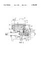
- FIG. 1is a diagrammatic representation of one example of the system
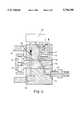
- FIG. 2shows one practical version of the system seen in FIG. 1,
- FIG. 3is a view similar to FIG. 1 showing another example of the system
- FIG. 4shows in diagrammatic form a modification to the system shown in FIG. 1, and
- FIGS. 5 and 6show further examples of the fuel system.
- the fuel systemcomprises a housing 10 in which is mounted a rotary cylindrical distributor member 11.
- the distributor memberis arranged to be rotated in timed relationship with the associated engine by means of a drive shaft 12 which is shown to be separated from the distributor member but which in practice is coupled thereto.
- the distributor memberincludes a delivery channel which is in the form of an outwardly extending delivery passage 13 formed in the distributor member and which is positioned to register in turn with a plurality of outlet ports 14 only one of which is shown.
- the outlet portsare connected to outlets 15 formed in the housing and there are as many outlet ports and outlets as there are engine cylinders.
- the outlets in useare connected to the injection nozzles of the associated engine and the usual delivery valves may be located in the outlets respectively.
- the delivery passage 13communicates with a circumferential groove 16 formed on the periphery of the distributor member and this is in constant communication with a passage 17 formed at least in part in the housing.
- the passage 17can communicate by way of an electromagnetically operable valve 18 with either a further passage 19 which is connected to an accumulator chamber 20 or with a drain passage 21.
- the valve 18is a two position valve and in one position as shown in the drawing, the passage 17 is connected to the drain 21. In the other position the connection to the drain is blocked off and the passage 17 communicates with the passage 19.
- the valveis controlled by an electromagnetic actuator which is supplied with current by an electronic control system 22.
- the control systemacts to control the speed of the engine in accordance with various engine operating parameters and also in accordance with a demand signal which is provided by a transducer responsive to the position of the operator controlled throttle pedal of the vehicle associated with the engine.
- the control systemmay also receive signals indicative of the engine temperature and air temperature etc. In addition, it receives a signal or signals from a transducer system 23 which is responsive to the passage past the sensor of teeth formed on the drive shaft 12. From this signal a signal can be derived indicative of the engine speed and also the engine position.
- valve 18can be operated to permit flow of fuel from the accumulator 20 to the outlet port and the fuel injection nozzle in communication therewith, so that fuel is supplied to the associated engine.
- the amount of fuel and the timing of deliveryare controlled by varying the length of time the valve member of the valve 18 is in the alternative position to that shown and the instant at which the valve operates.
- the pressure in the passage 17 and the groove and delivery passage within the distributor memberis reduced to drain pressure which may be the pressure within the pump housing.
- the accumulatoris charged with fuel by means of a cam actuated high pressure fuel pump 8 which conveniently is in the form of a pair of reciprocable pumping plungers 24 located within a diametrically disposed bore 25 formed in a part of the distributor member which extends from the housing. At their outer ends the plungers are engaged by shoes respectively each of which carries a roller which can engage with the internal peripheral surface of an annular cam ring 26.
- the bore 25is in constant communication with a circumferential groove 27 formed on the periphery of the distributor member and this communicates with the passage 19 and therefore the accumulator chamber 20 by means of a non-return valve 28 which may be constituted by one or more valves.
- the bore 25is also in communication with a diametrically disposed inlet passage 29 formed in the distributor member and which when the plungers are allowed to move outwardly, communicates with a filling port or ports 30 formed in the housing 10.
- the filling ports 30communicate with the outlet of a low pressure vane type pump 31 the rotary part of which conveniently is secured to the rotary distributor member 11.
- the pump 31has a fuel inlet 32 which by way of the usual filter 33, is connected to a source of supply.
- a pressure control valve 34which affords variable communication between the outlet and the inlet of the pump in order to control the fuel delivery pressure of the low pressure pump.
- the valve 34is electrically controlled with the control being effected by the control system 22.
- the control system 22also receives a signal from a sensor 35 which is responsive to the pressure of fuel within the accumulator.
- the cam ring 26is provided with a plurality of pairs of cam lobes the leading flanks of which considered in terms of the direction of rotation of the distributor member, impart inward movement to the plungers.
- the inlet passage 29is out of register with the filling ports 30 so that the fuel displaced by the plungers is supplied to the accumulator by way of the valve 28.
- the plungerscan move outwardly and it is whilst the plungers are under the control of the trailing flanks of the cam lobes that the passage 29 is in communication with a filling port 30.
- fuelcan flow to the bore 25 from the low pressure pump and the amount of fuel which flows can be varied by adjusting the outlet pressure of the low pressure pump using the control valve 34.
- Adjusting the outlet pressure of the low pressure pump 31does vary the quantity of fuel which flows into the bore 25 due to the restrictive nature of the passages which connect the outlet of the low pressure pump with the bore 25.
- the control systemcontrols the setting of the valve 34 in response to the signal provided by the pressure transducer 35. It is therefore possible to regulate the pressure in the accumulator using the valve 34 and the control valve 34 only has to deal with and be designed for use with fuel at a low pressure.
- the ability to regulate the pressure within the accumulatoris an important advantage of the present system over the usual cam actuated pump systems such as the normal distributor type pump in which the plungers form the high pressure pump, and the unit/injector type of pump.
- cam actuated pump systemssuch as the normal distributor type pump in which the plungers form the high pressure pump, and the unit/injector type of pump.
- the valve 18is shown as a two position spool valve with a single valve member. It can be replaced by two valves which are actuated separately with one valve acting when open to connect the accumulator to the passage 17 and the other acting when open to connect the passage 17 to the drain. In this way one valve can be used to start delivery of fuel and the other to terminate delivery of fuel. Other forms of valve can be used and in addition, instead of direct actuation by the actuator the valves may be actuated using a hydraulic or pneumatic arrangement.
- valve or valvesmay be operated by using a piezo-electric crystal stack or stacks.
- the low pressure pump 31is shown as having its rotary part mounted on the end of the distributor member remote from the drive shaft and is a vane type pump.
- the pumpmay however be driven directly by the drive shaft and be mounted in the portion of the housing which supports the drive shaft.
- the low pressure pumpmay be in the form of a single or an additional pair or more of plungers mounted in the distributor member.
- the additional plungersmust operate in antiphase to the plungers 24 and either have to be appropriately positioned relative to the plungers 24 or have to be actuated by cam lobes on a separate cam ring.
- the additional plungersmust be spring biased outwardly to provide the required pumping action, or otherwise positively primed for example by supplying the fuel at low pressure from an external pump.
- the fuelis supplied to the bore 25 by way of the inlet port or ports 30 and the passage 19, from the low pressure pump.
- a simple non-return valvemay be provided.
- a further pair of plungersmay be provided. These may be located in a further bore which is disposed in the same plane as the bore 25 or they may be located in a bore which is disposed in another plane. In the former case the further plungers would have further cam followers at their outer ends and be actuated by the same cam ring 26. Alternatively or in addition, the further bore can be located in spaced side-by-side relationship with the two bores being radially aligned and with adjacent pairs of plungers sharing a cam follower. Separate cam followers may be provided for the sets of plungers with separate cam rings.
- the shapes of at least the leading flanks of the cam lobesare similar and are dictated by the required fuel injection characteristic and the crests of the cam lobes are shaped to provide as rapid a termination of fuel delivery as possible.
- the number of cam lobesis dictated by the number of engine cylinders. In the present system the number of constraints on the cam lobe profile is reduced and the cam lobes can be shaped to reduce the driving torque fluctuation and to reduce the stresses in the material forming the crests of the cam lobes and the rollers.
- the number of pumping strokes of the plungers per revolution of the drive shaftcan be greater or less than the number of engine cylinders.
- FIG. 2shows a practical realization of the apparatus shown in FIG. 1.
- the valve 28is shown as being similar to a conventional non-return delivery valve such as may be incorporated in the outlets 15, and includes a valve member having a fluted guide portion which is located in a drilling formed in a part of the housing.
- the valve memberis provided with a valve head which is urged into engagement with a seating defined at the outer end of the drilling.
- the extent of movement of the valve member against the action of the springis limited by a stop which is formed by the reduced end of a spigot member 36 which extends from the housing 10.
- Alternative forms of valvecan be used such as a ball valve as shown in FIG. 1 or valve with a tubular guide portion.
- the spigot 36extends into an accumulator block 37 which is secured to the housing 10.
- a pair of blind drillings 38which have their open ends closed by plugs 39. Adjacent their closed ends the drillings are interconnected by a cross bore and in the wall of the block and extending into one of the drillings is a further bore.
- the spigotis provided with an axial passage which through cross passages interconnects the drillings 38 with the spring chamber of the valve 28.
- the drillings 38form an accumulator volume and during rotation of the distributor member the fuel in the drillings is pressurised to the desired pressure by the high pressure pump.
- the accumulator volumemay be formed in the portion of the housing which houses the distributor member.
- the accumulator volumemay be defined as an annular groove between the sleeve 40 which surrounds the distributor member and the housing part 10 in which the sleeve 40 is mounted. It is also possible to locate the accumulator away from the housing and to connect it to the spring chamber of the valve 28 by a suitable conduit.
- control system 22is located in an enclosure 42 which is secured on the accumulator block 37.
- the fuel inlet 41 to the low pressure pump 31conveniently passes through a wall of the enclosure to provide for cooling of the components of the control system.
- a heat insulating barrier layermay be interposed therebetween.
- An electrical socket 43is provided on the enclosure to enable connections to external sensors and a power supply to be effected.
- the control systemmay be positioned remote from the housing.
- the low pressure pump 31has its inlet connected to a source of fuel external of the housing 10 a vent must be provided on the housing to allow any fuel which leaks into the housing to escape. Such leakage can occur from the working clearance between the distributor member and the sleeve 40 and from the working clearances between the plungers and the bore or bores in which they are located.
- the inlet of the low pressure pump 31may be connected to the space within the housing in which case the source of fuel is connected to the interior of the housing.
- FIG. 1the delivery passage 13 is shown connected to the groove 16 by means of a short axial passage.
- the construction of the axial passagewould in practice require an axial drilling to be formed in the distributor member and closed by a plug.
- FIG. 2shows that the delivery passage 13A may be drilled obliquely from the groove 16.
- a part circumferential groove 44which is permanently connected to the outlet of the low pressure pump by way of a port 45 or by way of a further port (not shown) which is positioned diametrically opposite the port 45 and which is connected to the outlet of the low pressure pump.
- the outlet end of the delivery passage 13Ais located between the ends of the groove 44 and the arrangement is such that once an outlet port 14 has received fuel from the delivery passage 13A it is wiped by the groove 44 before it next receives fuel. In this way the outlet ports 14 after receiving fuel are brought to a common pressure before the next delivery of fuel. This action acts to ensure that any cavities in the fuel columns intermediate the outlet ports 14 and the delivery valves in the outlets 15 are dissipated.
- a side thrustwill be imposed on the distributor member by the fuel pressure in the delivery passage 13A and this can be partly compensated for by providing a short groove extending from the groove 16 at a position diametrically opposite the outlet end of the delivery passage 13A.
- a wiping portmay be formed in the distributor member in the same plane as the outlet end of the delivery passage 13A.
- the wiping portis connected by obliquely drilled passages in the distributor member to a circumferential groove on the distributor member which is in communication with the outlet of the low pressure pump.
- the extent of outward movement of the plungers 24 and hence the amount of fuel supplied to the accumulatorhas been determined by altering the output pressure of the low pressure pump 31 using the valve 34 associated with the low pressure pump 31.
- Other methodscan be used to control the outward movement of the plungers.
- the output pressure of the low pressure pumpcould be controlled by a simple relief valve and the flow of fuel to the bore 25 could be controlled by an axially or angularly adjustable throttle valve 30A the position of which may be controlled by an electrical actuator.
- the throttle valve 30Amay be located as shown in FIG. 1, in the passage which connects the outlet of the low pressure pump 34 with the transfer port 30 and would be controlled by the control system 22 in response to the signals provided by the sensor.
- a metering shuttlemay be utilised having an electrically controlled stroke control mechanism, or as a further alternative, the allowed stroke of the pumping plungers 24 can be varied using adjustable mechanical stops.
- a controllable relief valvemay be provided on the accumulator.
- FIG. 3shows how the concept of the present invention can be applied to a distributor pump of the kind in which the distributor member 50 besides rotating to perform the distributing function also is axially movable in a bore 51 to perform the pumping function.
- the delivery passageis shown at 52 and delivers fuel from the valve 18 to outlet ports 53 in turn.
- the low pressure pump 31delivers fuel to the closed end of the bore 51 through grooves 54 formed in the distributor member and which register in turn with an inlet port 55.
- the distributor memberis actuated by a face cam and roller mechanism 56 which is well known in the art and a return spring (not shown) is provided to move the distributor member out of the bore following its inward movement by the cam and roller mechanism.
- the quantity of fuel delivered to the accumulatormay be determined by controlling the output pressure of the low pressure pump 31 or it could be controlled by spilling surplus fuel.
- the accumulator pressurecan be chosen so that the pressure is adequate at high engine speeds without being excessive at idle speed.
- reducing the pressuremeans that the effective fuel capacity of the accumulator is reduced so that if for example the operator of the engine makes a sudden demand for increased engine power there will be insufficient fuel available in the accumulator to meet the demand. The response of the engine will therefore be impaired.
- This difficultymay be overcome by providing as shown in FIG. 4, a further accumulator 60 which contains fuel at a lower pressure.
- the further accumulator 60may be charged with fuel through a pressure reducing valve 61 from the main accumulator 20 or by a separate high pressure pump 62 formed by a separate set of pumping plungers carried by the distributor member, the existing high pressure pump being shown at 63.
- Each of the pumpswould require a non-return valve as illustrated at 28 in FIG.
- valves 64, 65associated with the accumulators 20, 60 respectively.
- the valves in this caseare simple ON/OFF valves in order to prevent loss of fuel to drain and a further ON/OFF valve 66 is provided to provide for termination of delivery of fuel to the engine.
- This arrangementcan also be used to provide control of the initial rate of fuel delivery through the outlets 15 by operating the valves 65, 64 in turn when it is required to deliver fuel to the engine.
- a non-return valve in series with the valve 65 associated with the further accumulator 60would be required to prevent flow of fuel between the two accumulators.
- the cam lobescan be designed to reduce driving torque fluctuation. This is achieved by making the leading flanks of the cam lobes which impart inward movement to the plungers 24 less steep than in a conventional distributor type fuel pump. It is proposed to supply fuel displaced by the plungers to the delivery passage in order to provide an initial flow of fuel at a reduced rate to the engine.
- the plungersmay also be utilized to supply all the fuel for engine idling or other low rate requirements. In this event the number of pumping strokes of the plungers per revolution of the distributor member must be the same as the number of engine cylinders.
- the high pressure pump constituted by the plungers 24,is utilised only to charge the accumulator 20 and for this purpose is connected to the accumulator by way of the non-return valve 28.
- the pressure within the accumulatormay be controlled using a relief valve or alternatively an arrangement may be provided to control the volume of fuel delivered by the high pressure pump.
- One way of reducing the fuel flow from the high pressure pumpis to use a throttle to restrict the rate at which fuel flows into the pump.
- some form of plunger stroke controlmay be provided.
- valve 71In operation, prior to the start of fuel delivery the valve 71 is closed and the valve 18 is in the second position in which the passages 17 and 21 are in communication with each other.
- the valve 18When the delivery passage 13 has moved into register with an outlet port 14 the valve 18 is moved to its first position in which the passages 17 and 19 are connected together so that fuel can flow from the accumulator 20 to the delivery passage 13.
- the rate of flow of fuelis controlled by the size of the restrictor 70.
- the valve 71When it is deemed that sufficient fuel has been supplied at the restricted rate, the valve 71 is opened to allow fuel flow at a substantially unrestricted rate and when sufficient fuel has been supplied to the engine the valve 18 is moved to its second position so that the flow of fuel from the accumulator is halted and the delivery passage 13 is vented to the drain.
- valve 71Before the next delivery of fuel takes place the valve 71 is closed and the process is repeated with fuel being supplied to the outlets 14 in turn.
- the high pressure pumpis conveniently arranged to charge the accumulator with fuel each time delivery of fuel takes place to the associated engine and the delivery of fuel by the high pressure pump to the accumulator may commence whilst fuel is being supplied to the engine.
- variable lift valvemay be provided in the passage 19.
- the variable lift valvemay be utilised to initiate delivery of fuel whilst the valve 19 is in its first position, with the valve 19 being used to terminate delivery of fuel by moving it to its second position.
- the high pressure pumpis utilised to charge the accumulator 20 by way of a non-return valve 28.
- a first ON/OFF valve 72is provided to connect the accumulator 20 to the delivery passage 13 and when this valve is opened fuel flows to the engine at the maximum rate.
- a second accumulator 73is provided in which fuel is stored at a lower pressure and this accumulator can be connected to the delivery passage 13 by way of a second ON/OFF valve 74.
- a third ON/OFF valve 75is provided to connect the delivery passage 13 to a drain.
- valve 75In operation, when the delivery passage 13 registers with an outlet port 14, the valve 75 is closed and the valve 74 opened to allow fuel to flow at a reduced rate to the associated engine because of the lower pressure in the accumulator 73. When sufficient fuel has been supplied at the reduced rate the valve 72 is opened and the valve 74 closed so that the rate of flow of fuel to the engine increases due to the higher pressure in the accumulator 20. Termination of delivery of fuel to the engine is achieved by closing the valve 72 and opening the valve 75.
- valve 75is opened to terminate delivery of fuel to provide so called pilot injection of fuel and at the appropriate time the valve 75 is closed and the valve 72 opened to provide the main delivery of fuel.
- a separate high pressure pumpmay be provided in order to pressurise the accumulator 73 .
- the accumulator 73may be charged from the accumulator 20 by appropriate operation of the valves 72 and 74 preferably during the time when the delivery passage 13 is out of register with an outlet port 14.
- Individual relief valvesmay be utilised to control the pressures in the accumulators 20 and 73 or the pressures particularly in the accumulator 20, may be controlled by appropriate operation of the valves 72 and 75.
Landscapes
- Engineering & Computer Science (AREA)
- Chemical & Material Sciences (AREA)
- Combustion & Propulsion (AREA)
- Mechanical Engineering (AREA)
- General Engineering & Computer Science (AREA)
- Fuel-Injection Apparatus (AREA)
Abstract
Description
Claims (11)
Applications Claiming Priority (4)
| Application Number | Priority Date | Filing Date | Title |
|---|---|---|---|
| GB9318969 | 1993-09-14 | ||
| GB9318963 | 1993-09-14 | ||
| GB939318969AGB9318969D0 (en) | 1993-09-14 | 1993-09-14 | Fuel supply apparatus |
| GB939318963AGB9318963D0 (en) | 1993-09-14 | 1993-09-14 | Fuel system |
Publications (1)
| Publication Number | Publication Date |
|---|---|
| US5746180Atrue US5746180A (en) | 1998-05-05 |
Family
ID=26303511
Family Applications (2)
| Application Number | Title | Priority Date | Filing Date |
|---|---|---|---|
| US08/303,695Expired - LifetimeUS5746180A (en) | 1993-09-14 | 1994-09-09 | Fuel supply apparatus |
| US08/303,696Expired - LifetimeUS5427066A (en) | 1993-09-14 | 1994-09-09 | Fuel system |
Family Applications After (1)
| Application Number | Title | Priority Date | Filing Date |
|---|---|---|---|
| US08/303,696Expired - LifetimeUS5427066A (en) | 1993-09-14 | 1994-09-09 | Fuel system |
Country Status (5)
| Country | Link |
|---|---|
| US (2) | US5746180A (en) |
| EP (3) | EP0785356B1 (en) |
| JP (2) | JPH07180635A (en) |
| DE (3) | DE69424448T2 (en) |
| ES (3) | ES2115882T3 (en) |
Cited By (32)
| Publication number | Priority date | Publication date | Assignee | Title |
|---|---|---|---|---|
| US6035829A (en)* | 1998-01-13 | 2000-03-14 | Siemens Aktiengesellschaft | Method of specifying an injection-pressure setpoint value in an accumulator injection system |
| WO2002050421A1 (en)* | 2000-12-06 | 2002-06-27 | Yanmar Co., Ltd. | Three-way valve of accumulator distributing type fuel injection pump |
| US20040055574A1 (en)* | 2002-07-01 | 2004-03-25 | Shoji Namekawa | Fuel injector and diesel engine comprising the same |
| WO2013040116A1 (en) | 2011-09-13 | 2013-03-21 | Monsanto Technology Llc | Methods and compositions for weed control |
| US20140261321A1 (en)* | 2013-03-13 | 2014-09-18 | Electro-Motive Diesel, Inc. | Fuel system having rotary distributor |
| US9121022B2 (en) | 2010-03-08 | 2015-09-01 | Monsanto Technology Llc | Method for controlling herbicide-resistant plants |
| US9422558B2 (en) | 2011-09-13 | 2016-08-23 | Monsanto Technology Llc | Methods and compositions for weed control |
| US9422557B2 (en) | 2011-09-13 | 2016-08-23 | Monsanto Technology Llc | Methods and compositions for weed control |
| US9540642B2 (en) | 2013-11-04 | 2017-01-10 | The United States Of America, As Represented By The Secretary Of Agriculture | Compositions and methods for controlling arthropod parasite and pest infestations |
| US9777288B2 (en) | 2013-07-19 | 2017-10-03 | Monsanto Technology Llc | Compositions and methods for controlling leptinotarsa |
| US9850496B2 (en) | 2013-07-19 | 2017-12-26 | Monsanto Technology Llc | Compositions and methods for controlling Leptinotarsa |
| US10041068B2 (en) | 2013-01-01 | 2018-08-07 | A. B. Seeds Ltd. | Isolated dsRNA molecules and methods of using same for silencing target molecules of interest |
| US10240161B2 (en) | 2012-05-24 | 2019-03-26 | A.B. Seeds Ltd. | Compositions and methods for silencing gene expression |
| US10334848B2 (en) | 2014-01-15 | 2019-07-02 | Monsanto Technology Llc | Methods and compositions for weed control using EPSPS polynucleotides |
| US10378012B2 (en) | 2014-07-29 | 2019-08-13 | Monsanto Technology Llc | Compositions and methods for controlling insect pests |
| US10557138B2 (en) | 2013-12-10 | 2020-02-11 | Beeologics, Inc. | Compositions and methods for virus control in Varroa mite and bees |
| US10568328B2 (en) | 2013-03-15 | 2020-02-25 | Monsanto Technology Llc | Methods and compositions for weed control |
| US10609930B2 (en) | 2013-03-13 | 2020-04-07 | Monsanto Technology Llc | Methods and compositions for weed control |
| US10612019B2 (en) | 2013-03-13 | 2020-04-07 | Monsanto Technology Llc | Methods and compositions for weed control |
| US10655136B2 (en) | 2015-06-03 | 2020-05-19 | Monsanto Technology Llc | Methods and compositions for introducing nucleic acids into plants |
| US10683505B2 (en) | 2013-01-01 | 2020-06-16 | Monsanto Technology Llc | Methods of introducing dsRNA to plant seeds for modulating gene expression |
| US10760086B2 (en) | 2011-09-13 | 2020-09-01 | Monsanto Technology Llc | Methods and compositions for weed control |
| US10801028B2 (en) | 2009-10-14 | 2020-10-13 | Beeologics Inc. | Compositions for controlling Varroa mites in bees |
| US10808249B2 (en) | 2011-09-13 | 2020-10-20 | Monsanto Technology Llc | Methods and compositions for weed control |
| US10806146B2 (en) | 2011-09-13 | 2020-10-20 | Monsanto Technology Llc | Methods and compositions for weed control |
| US10829828B2 (en) | 2011-09-13 | 2020-11-10 | Monsanto Technology Llc | Methods and compositions for weed control |
| US10883103B2 (en) | 2015-06-02 | 2021-01-05 | Monsanto Technology Llc | Compositions and methods for delivery of a polynucleotide into a plant |
| US10888579B2 (en) | 2007-11-07 | 2021-01-12 | Beeologics Inc. | Compositions for conferring tolerance to viral disease in social insects, and the use thereof |
| US10968449B2 (en) | 2015-01-22 | 2021-04-06 | Monsanto Technology Llc | Compositions and methods for controlling Leptinotarsa |
| US10988764B2 (en) | 2014-06-23 | 2021-04-27 | Monsanto Technology Llc | Compositions and methods for regulating gene expression via RNA interference |
| US11091770B2 (en) | 2014-04-01 | 2021-08-17 | Monsanto Technology Llc | Compositions and methods for controlling insect pests |
| US11807857B2 (en) | 2014-06-25 | 2023-11-07 | Monsanto Technology Llc | Methods and compositions for delivering nucleic acids to plant cells and regulating gene expression |
Families Citing this family (20)
| Publication number | Priority date | Publication date | Assignee | Title |
|---|---|---|---|---|
| GB9411345D0 (en)* | 1994-06-07 | 1994-07-27 | Lucas Ind Plc | Fuel supply system |
| GB9422864D0 (en)* | 1994-11-12 | 1995-01-04 | Lucas Ind Plc | Fuel system |
| GB2299138A (en)* | 1995-03-24 | 1996-09-25 | Lucas Ind Plc | Fuel system |
| US5732679A (en)* | 1995-04-27 | 1998-03-31 | Isuzu Motors Limited | Accumulator-type fuel injection system |
| GB9509733D0 (en)* | 1995-05-13 | 1995-07-05 | Lucas Ind Plc | Fuel pumping apparatus |
| GB2310889A (en)* | 1996-03-05 | 1997-09-10 | Lucas Ind Plc | Fuel supply system for solenoid-actuated fuel injectors |
| GB9606493D0 (en)* | 1996-03-23 | 1996-06-05 | Lucas Ind Plc | Fuel pump |
| DE19716221B4 (en)* | 1997-04-18 | 2007-06-21 | Robert Bosch Gmbh | Fuel injection device with pre-injection and main injection in internal combustion engines, in particular for hard to ignite fuels |
| DE19854509C2 (en) | 1998-11-25 | 2000-11-23 | Siemens Ag | Device for generating a variable volume flow when supplying fuel |
| DE19904074A1 (en)* | 1999-02-02 | 2000-08-03 | Bosch Gmbh Robert | Delivery arrangement for liquid medium has step change transmission between electric motor of electric drive arrangement and distributor arrangement |
| DE19904041A1 (en)* | 1999-02-02 | 2000-08-17 | Bosch Gmbh Robert | Input device for fluid medium, valve device of which has several valve units |
| DE19904075A1 (en)* | 1999-02-02 | 2000-08-03 | Bosch Gmbh Robert | Liquid medium delivery arrangement has valve unit between pressure reservoir and distributor arrangement to determine start of delivery and dosing of liquid medium |
| DE19952000C2 (en)* | 1999-10-28 | 2001-08-16 | Siemens Ag | Device for generating a variable volume flow for a pump |
| DE19954206A1 (en)* | 1999-11-11 | 2001-05-23 | Bosch Gmbh Robert | Fuel injection system |
| RU2242631C2 (en)* | 2002-06-03 | 2004-12-20 | Иркутская государственная сельскохозяйственная академия | Diesel engine fuel feed device |
| WO2004070190A1 (en)* | 2003-01-30 | 2004-08-19 | Robert Bosch Gmbh | Fuel injector pump with trapped volume |
| US7398763B2 (en)* | 2005-11-09 | 2008-07-15 | Caterpillar Inc. | Multi-source fuel system for variable pressure injection |
| US7431017B2 (en) | 2006-05-24 | 2008-10-07 | Caterpillar Inc. | Multi-source fuel system having closed loop pressure control |
| US7392791B2 (en) | 2006-05-31 | 2008-07-01 | Caterpillar Inc. | Multi-source fuel system for variable pressure injection |
| US7353800B2 (en) | 2006-05-24 | 2008-04-08 | Caterpillar Inc. | Multi-source fuel system having grouped injector pressure control |
Citations (9)
| Publication number | Priority date | Publication date | Assignee | Title |
|---|---|---|---|---|
| GB2079366A (en)* | 1980-07-03 | 1982-01-20 | Lucas Industries Ltd | Fuel system for compression ignition engines |
| US4601274A (en)* | 1984-07-13 | 1986-07-22 | Lucas Industries | Fuel pumping apparatus |
| US4757795A (en)* | 1986-04-21 | 1988-07-19 | Stanadyne, Inc. | Method and apparatus for regulating fuel injection timing and quantity |
| US4767288A (en)* | 1981-06-11 | 1988-08-30 | Robert Bosch Gmbh | Fuel injection pump |
| US5005548A (en)* | 1989-07-06 | 1991-04-09 | Robert Bosch Gmbh | Fuel injection pump |
| US5078113A (en)* | 1989-02-04 | 1992-01-07 | Robert Bosch Gmbh | Reservoir-type fuel injection system |
| US5215060A (en)* | 1991-07-16 | 1993-06-01 | Stanadyne Automotive Corp. | Fuel system for rotary distributor fuel injection pump |
| WO1993022554A1 (en)* | 1992-04-25 | 1993-11-11 | Robert Bosch Gmbh | Fuel injection device for internal combustion engines |
| US5327869A (en)* | 1990-07-21 | 1994-07-12 | Robert Bosch Gmbh | Fuel injection device for spark-ignition internal combustion engines |
Family Cites Families (9)
| Publication number | Priority date | Publication date | Assignee | Title |
|---|---|---|---|---|
| FR2093250A5 (en)* | 1970-06-08 | 1972-01-28 | Peugeot | |
| US4083345A (en)* | 1975-10-14 | 1978-04-11 | Stanadyne, Inc. | Fuel injection pump |
| ES481775A1 (en)* | 1978-08-03 | 1980-02-16 | Lucas Industries Ltd | Liquid fuel pumping apparatus |
| DE3011831A1 (en)* | 1980-03-27 | 1981-10-01 | Robert Bosch Gmbh, 7000 Stuttgart | FUEL INJECTION PUMP FOR INTERNAL COMBUSTION ENGINES |
| DE3248713A1 (en)* | 1982-12-31 | 1984-07-05 | Robert Bosch Gmbh, 7000 Stuttgart | METHOD FOR INJECTION OF FUEL AND FUEL INJECTION DEVICE FOR CARRYING OUT THE METHOD |
| GB8417861D0 (en)* | 1984-07-13 | 1984-08-15 | Lucas Ind Plc | Fuel pumping apparatus |
| FR2586456B1 (en)* | 1985-08-21 | 1989-07-07 | Lucas France | FUEL INJECTION PUMP WITH ROTARY DISTRIBUTOR FOR SUPPLYING INTERNAL COMBUSTION ENGINES |
| DE3844363A1 (en)* | 1988-12-30 | 1990-07-05 | Bosch Gmbh Robert | Electrically controlled fuel injection pump |
| DE4304967A1 (en)* | 1992-04-25 | 1993-10-28 | Bosch Gmbh Robert | Fuel injection unit for IC engine with high pressure pump - drawing fuel via filling valve to pump working chamber defined by pump piston and delivers by valve at high pressure to HP storage |
- 1994
- 1994-09-05EPEP97200928Apatent/EP0785356B1/ennot_activeExpired - Lifetime
- 1994-09-05ESES94306529Tpatent/ES2115882T3/ennot_activeExpired - Lifetime
- 1994-09-05ESES94306533Tpatent/ES2115883T3/ennot_activeExpired - Lifetime
- 1994-09-05DEDE69424448Tpatent/DE69424448T2/ennot_activeExpired - Lifetime
- 1994-09-05DEDE69409743Tpatent/DE69409743T2/ennot_activeExpired - Lifetime
- 1994-09-05ESES97200928Tpatent/ES2146952T3/ennot_activeExpired - Lifetime
- 1994-09-05EPEP94306533Apatent/EP0643221B1/ennot_activeExpired - Lifetime
- 1994-09-05DEDE69409741Tpatent/DE69409741T2/ennot_activeExpired - Lifetime
- 1994-09-05EPEP94306529Apatent/EP0643220B1/ennot_activeExpired - Lifetime
- 1994-09-09USUS08/303,695patent/US5746180A/ennot_activeExpired - Lifetime
- 1994-09-09USUS08/303,696patent/US5427066A/ennot_activeExpired - Lifetime
- 1994-09-12JPJP6242359Apatent/JPH07180635A/enactivePending
- 1994-09-14JPJP6244893Apatent/JPH07167001A/enactivePending
Patent Citations (9)
| Publication number | Priority date | Publication date | Assignee | Title |
|---|---|---|---|---|
| GB2079366A (en)* | 1980-07-03 | 1982-01-20 | Lucas Industries Ltd | Fuel system for compression ignition engines |
| US4767288A (en)* | 1981-06-11 | 1988-08-30 | Robert Bosch Gmbh | Fuel injection pump |
| US4601274A (en)* | 1984-07-13 | 1986-07-22 | Lucas Industries | Fuel pumping apparatus |
| US4757795A (en)* | 1986-04-21 | 1988-07-19 | Stanadyne, Inc. | Method and apparatus for regulating fuel injection timing and quantity |
| US5078113A (en)* | 1989-02-04 | 1992-01-07 | Robert Bosch Gmbh | Reservoir-type fuel injection system |
| US5005548A (en)* | 1989-07-06 | 1991-04-09 | Robert Bosch Gmbh | Fuel injection pump |
| US5327869A (en)* | 1990-07-21 | 1994-07-12 | Robert Bosch Gmbh | Fuel injection device for spark-ignition internal combustion engines |
| US5215060A (en)* | 1991-07-16 | 1993-06-01 | Stanadyne Automotive Corp. | Fuel system for rotary distributor fuel injection pump |
| WO1993022554A1 (en)* | 1992-04-25 | 1993-11-11 | Robert Bosch Gmbh | Fuel injection device for internal combustion engines |
Cited By (45)
| Publication number | Priority date | Publication date | Assignee | Title |
|---|---|---|---|---|
| US6035829A (en)* | 1998-01-13 | 2000-03-14 | Siemens Aktiengesellschaft | Method of specifying an injection-pressure setpoint value in an accumulator injection system |
| WO2002050421A1 (en)* | 2000-12-06 | 2002-06-27 | Yanmar Co., Ltd. | Three-way valve of accumulator distributing type fuel injection pump |
| US20040055574A1 (en)* | 2002-07-01 | 2004-03-25 | Shoji Namekawa | Fuel injector and diesel engine comprising the same |
| US6895937B2 (en) | 2002-07-01 | 2005-05-24 | Mitsubishi Heavy Industries, Ltd. | Fuel injector and diesel engine comprising the same |
| US10888579B2 (en) | 2007-11-07 | 2021-01-12 | Beeologics Inc. | Compositions for conferring tolerance to viral disease in social insects, and the use thereof |
| US10801028B2 (en) | 2009-10-14 | 2020-10-13 | Beeologics Inc. | Compositions for controlling Varroa mites in bees |
| US11812738B2 (en) | 2010-03-08 | 2023-11-14 | Monsanto Technology Llc | Polynucleotide molecules for gene regulation in plants |
| US9988634B2 (en) | 2010-03-08 | 2018-06-05 | Monsanto Technology Llc | Polynucleotide molecules for gene regulation in plants |
| US9121022B2 (en) | 2010-03-08 | 2015-09-01 | Monsanto Technology Llc | Method for controlling herbicide-resistant plants |
| WO2013040116A1 (en) | 2011-09-13 | 2013-03-21 | Monsanto Technology Llc | Methods and compositions for weed control |
| US9422557B2 (en) | 2011-09-13 | 2016-08-23 | Monsanto Technology Llc | Methods and compositions for weed control |
| US9422558B2 (en) | 2011-09-13 | 2016-08-23 | Monsanto Technology Llc | Methods and compositions for weed control |
| US9416363B2 (en) | 2011-09-13 | 2016-08-16 | Monsanto Technology Llc | Methods and compositions for weed control |
| US10760086B2 (en) | 2011-09-13 | 2020-09-01 | Monsanto Technology Llc | Methods and compositions for weed control |
| US10806146B2 (en) | 2011-09-13 | 2020-10-20 | Monsanto Technology Llc | Methods and compositions for weed control |
| US10808249B2 (en) | 2011-09-13 | 2020-10-20 | Monsanto Technology Llc | Methods and compositions for weed control |
| US10829828B2 (en) | 2011-09-13 | 2020-11-10 | Monsanto Technology Llc | Methods and compositions for weed control |
| EP3434780A1 (en) | 2011-09-13 | 2019-01-30 | Monsanto Technology LLC | Methods and compositions for weed control |
| US10934555B2 (en) | 2012-05-24 | 2021-03-02 | Monsanto Technology Llc | Compositions and methods for silencing gene expression |
| US10240162B2 (en) | 2012-05-24 | 2019-03-26 | A.B. Seeds Ltd. | Compositions and methods for silencing gene expression |
| US10240161B2 (en) | 2012-05-24 | 2019-03-26 | A.B. Seeds Ltd. | Compositions and methods for silencing gene expression |
| US10041068B2 (en) | 2013-01-01 | 2018-08-07 | A. B. Seeds Ltd. | Isolated dsRNA molecules and methods of using same for silencing target molecules of interest |
| US10683505B2 (en) | 2013-01-01 | 2020-06-16 | Monsanto Technology Llc | Methods of introducing dsRNA to plant seeds for modulating gene expression |
| US20140261321A1 (en)* | 2013-03-13 | 2014-09-18 | Electro-Motive Diesel, Inc. | Fuel system having rotary distributor |
| US10609930B2 (en) | 2013-03-13 | 2020-04-07 | Monsanto Technology Llc | Methods and compositions for weed control |
| US10612019B2 (en) | 2013-03-13 | 2020-04-07 | Monsanto Technology Llc | Methods and compositions for weed control |
| US10568328B2 (en) | 2013-03-15 | 2020-02-25 | Monsanto Technology Llc | Methods and compositions for weed control |
| US9777288B2 (en) | 2013-07-19 | 2017-10-03 | Monsanto Technology Llc | Compositions and methods for controlling leptinotarsa |
| US10597676B2 (en) | 2013-07-19 | 2020-03-24 | Monsanto Technology Llc | Compositions and methods for controlling Leptinotarsa |
| US11377667B2 (en) | 2013-07-19 | 2022-07-05 | Monsanto Technology Llc | Compositions and methods for controlling Leptinotarsa |
| US9850496B2 (en) | 2013-07-19 | 2017-12-26 | Monsanto Technology Llc | Compositions and methods for controlling Leptinotarsa |
| US9856495B2 (en) | 2013-07-19 | 2018-01-02 | Monsanto Technology Llc | Compositions and methods for controlling Leptinotarsa |
| US10927374B2 (en) | 2013-11-04 | 2021-02-23 | Monsanto Technology Llc | Compositions and methods for controlling arthropod parasite and pest infestations |
| US9540642B2 (en) | 2013-11-04 | 2017-01-10 | The United States Of America, As Represented By The Secretary Of Agriculture | Compositions and methods for controlling arthropod parasite and pest infestations |
| US10100306B2 (en) | 2013-11-04 | 2018-10-16 | Monsanto Technology Llc | Compositions and methods for controlling arthropod parasite and pest infestations |
| US10557138B2 (en) | 2013-12-10 | 2020-02-11 | Beeologics, Inc. | Compositions and methods for virus control in Varroa mite and bees |
| US10334848B2 (en) | 2014-01-15 | 2019-07-02 | Monsanto Technology Llc | Methods and compositions for weed control using EPSPS polynucleotides |
| US11091770B2 (en) | 2014-04-01 | 2021-08-17 | Monsanto Technology Llc | Compositions and methods for controlling insect pests |
| US10988764B2 (en) | 2014-06-23 | 2021-04-27 | Monsanto Technology Llc | Compositions and methods for regulating gene expression via RNA interference |
| US11807857B2 (en) | 2014-06-25 | 2023-11-07 | Monsanto Technology Llc | Methods and compositions for delivering nucleic acids to plant cells and regulating gene expression |
| US11124792B2 (en) | 2014-07-29 | 2021-09-21 | Monsanto Technology Llc | Compositions and methods for controlling insect pests |
| US10378012B2 (en) | 2014-07-29 | 2019-08-13 | Monsanto Technology Llc | Compositions and methods for controlling insect pests |
| US10968449B2 (en) | 2015-01-22 | 2021-04-06 | Monsanto Technology Llc | Compositions and methods for controlling Leptinotarsa |
| US10883103B2 (en) | 2015-06-02 | 2021-01-05 | Monsanto Technology Llc | Compositions and methods for delivery of a polynucleotide into a plant |
| US10655136B2 (en) | 2015-06-03 | 2020-05-19 | Monsanto Technology Llc | Methods and compositions for introducing nucleic acids into plants |
Also Published As
| Publication number | Publication date |
|---|---|
| DE69409743D1 (en) | 1998-05-28 |
| JPH07180635A (en) | 1995-07-18 |
| US5427066A (en) | 1995-06-27 |
| EP0643220A1 (en) | 1995-03-15 |
| EP0785356A3 (en) | 1997-10-29 |
| EP0643221A1 (en) | 1995-03-15 |
| ES2115883T3 (en) | 1998-07-01 |
| DE69424448T2 (en) | 2000-12-21 |
| JPH07167001A (en) | 1995-07-04 |
| EP0643221B1 (en) | 1998-04-22 |
| ES2115882T3 (en) | 1998-07-01 |
| DE69409741D1 (en) | 1998-05-28 |
| ES2146952T3 (en) | 2000-08-16 |
| DE69409741T2 (en) | 1999-04-08 |
| DE69424448D1 (en) | 2000-06-15 |
| EP0643220B1 (en) | 1998-04-22 |
| EP0785356A2 (en) | 1997-07-23 |
| DE69409743T2 (en) | 1998-10-22 |
| EP0785356B1 (en) | 2000-05-10 |
Similar Documents
| Publication | Publication Date | Title |
|---|---|---|
| US5746180A (en) | Fuel supply apparatus | |
| US4838233A (en) | Pilot injection system for fuel injection pump | |
| US4407250A (en) | Fuel injection system | |
| US4601274A (en) | Fuel pumping apparatus | |
| US4398519A (en) | Fuel injection apparatus for internal combustion engines, in particular for diesel engines | |
| EP0652394B1 (en) | Control valve | |
| EP0524132B1 (en) | Fuel system for rotary distributor fuel injection pump | |
| US4426977A (en) | Dual solenoid distributor pump system | |
| US4418671A (en) | Dual solenoid distributor pump | |
| US4469069A (en) | Fuel injection device | |
| US4426983A (en) | Liquid fuel pumping apparatus | |
| US4310291A (en) | Liquid fuel pumping apparatus | |
| GB2275307A (en) | I.c.engine high pressure distributor fuel injection system | |
| US4798189A (en) | Fuel injection pump | |
| US4764092A (en) | Liquid fuel injection pump | |
| EP0715071B1 (en) | Fuel pumping apparatus | |
| GB2028916A (en) | Fuel Supply System for Internal Combustion Engine | |
| US4301777A (en) | Fuel injection pump | |
| JPS61190164A (en) | Fuel injection pump for diesel engine | |
| EP0644327B1 (en) | Fuel pump | |
| US4598683A (en) | Fuel injection pump of the distribution type | |
| US4232644A (en) | Fuel pumping apparatus | |
| US5619970A (en) | Fuel pumping apparatus | |
| US5666921A (en) | Fuel supply apparatus | |
| EP0640760B1 (en) | Fuel pump |
Legal Events
| Date | Code | Title | Description |
|---|---|---|---|
| AS | Assignment | Owner name:LUCAS INDUSTRIES PUBLIC LIMITED COMPANY OF BRUETON Free format text:ASSIGNMENT OF ASSIGNORS INTEREST;ASSIGNORS:JEFFERSON, JOHN RODERICK;COLLINGBORN, PETER ALBAN GEORGE;COOKE, MICHAEL PETER;AND OTHERS;REEL/FRAME:008526/0759 Effective date:19940822 | |
| STCF | Information on status: patent grant | Free format text:PATENTED CASE | |
| AS | Assignment | Owner name:DELPHI TECHNOLOGIES, INC., MICHIGAN Free format text:ASSIGNMENT OF ASSIGNORS INTEREST;ASSIGNORS:LUCAS LIMITED;LUCAS INDUSTRIES LIMITED;REEL/FRAME:011742/0367 Effective date:20010409 | |
| FPAY | Fee payment | Year of fee payment:4 | |
| REMI | Maintenance fee reminder mailed | ||
| FPAY | Fee payment | Year of fee payment:8 | |
| SULP | Surcharge for late payment | Year of fee payment:7 | |
| FPAY | Fee payment | Year of fee payment:12 | |
| AS | Assignment | Owner name:DELPHI TECHNOLOGIES HOLDING S.ARL,LUXEMBOURG Free format text:ASSIGNMENT OF ASSIGNORS INTEREST;ASSIGNOR:DELPHI TECHNOLOGIES, INC.;REEL/FRAME:024233/0854 Effective date:20100406 Owner name:DELPHI TECHNOLOGIES HOLDING S.ARL, LUXEMBOURG Free format text:ASSIGNMENT OF ASSIGNORS INTEREST;ASSIGNOR:DELPHI TECHNOLOGIES, INC.;REEL/FRAME:024233/0854 Effective date:20100406 | |
| AS | Assignment | Owner name:DELPHI INTERNATIONAL OPERATIONS LUXEMBOURG S.A.R.L Free format text:MERGER;ASSIGNOR:DELPHI TECHNOLOGIES HOLDING S.ARL;REEL/FRAME:032227/0879 Effective date:20140116 |