US5745808A - Camera exposure control system using variable-length exposure tables - Google Patents
Camera exposure control system using variable-length exposure tablesDownload PDFInfo
- Publication number
- US5745808A US5745808AUS08/565,371US56537195AUS5745808AUS 5745808 AUS5745808 AUS 5745808AUS 56537195 AUS56537195 AUS 56537195AUS 5745808 AUS5745808 AUS 5745808A
- Authority
- US
- United States
- Prior art keywords
- exposure
- values
- value
- image
- camera
- Prior art date
- Legal status (The legal status is an assumption and is not a legal conclusion. Google has not performed a legal analysis and makes no representation as to the accuracy of the status listed.)
- Expired - Lifetime
Links
Images


Classifications
- G—PHYSICS
- G03—PHOTOGRAPHY; CINEMATOGRAPHY; ANALOGOUS TECHNIQUES USING WAVES OTHER THAN OPTICAL WAVES; ELECTROGRAPHY; HOLOGRAPHY
- G03B—APPARATUS OR ARRANGEMENTS FOR TAKING PHOTOGRAPHS OR FOR PROJECTING OR VIEWING THEM; APPARATUS OR ARRANGEMENTS EMPLOYING ANALOGOUS TECHNIQUES USING WAVES OTHER THAN OPTICAL WAVES; ACCESSORIES THEREFOR
- G03B7/00—Control of exposure by setting shutters, diaphragms or filters, separately or conjointly
- G03B7/08—Control effected solely on the basis of the response, to the intensity of the light received by the camera, of a built-in light-sensitive device
- G03B7/091—Digital circuits
- G03B7/095—Digital circuits for control of aperture
- H—ELECTRICITY
- H04—ELECTRIC COMMUNICATION TECHNIQUE
- H04N—PICTORIAL COMMUNICATION, e.g. TELEVISION
- H04N23/00—Cameras or camera modules comprising electronic image sensors; Control thereof
- H04N23/70—Circuitry for compensating brightness variation in the scene
- H04N23/71—Circuitry for evaluating the brightness variation
- H—ELECTRICITY
- H04—ELECTRIC COMMUNICATION TECHNIQUE
- H04N—PICTORIAL COMMUNICATION, e.g. TELEVISION
- H04N23/00—Cameras or camera modules comprising electronic image sensors; Control thereof
- H04N23/70—Circuitry for compensating brightness variation in the scene
- H04N23/73—Circuitry for compensating brightness variation in the scene by influencing the exposure time
Definitions
- the inventionrelates generally to the field of photography, and in particular to the implementation of exposure control in a photographic system..
- Both electronic and film camerasordinarily vary image acquisition parameters to properly expose an image receiver, such as a film or an electronic image sensor, for a wide range of scene illumination levels. For instance, such cameras decide proper settings for an exposure time and an aperture in order to expose the film or the image sensor effectively. In addition, an electronic camera may need to set the output gain applied to the sensor. These parameters frequently exist as values in a table stored in an electronic memory, particularly if there are many values which these parameters can take. In systems which use such exposure tables, the ambient light of the scene is measured by a sensor (either a dedicated exposure sensor or, for an electronic camera, sometimes the image sensor itself). The resulting digital value or voltage (the digitized output of the exposure sensor module) is converted to an evaluated exposure value that is then used to dereference the exposure table to determine the settings which properly expose the image sensor or the film for the measured scene light level.
- the footlamberts column for the light rangeis exemplary of a range of real-life light levels. It is possible to find the exposure value for any of these light levels for a given receiver speed (ISO) by drawing a line between the operating ISO and the light level. The intersection of this line with the middle column specifies the exposure value for the measured light level and operating ISO. This will represent the scene light level in a relative log space, which is the space in which exposure tables are stored. It is clear that the normal light range generally falls in the range of 0-20 EV, or approximately 20 stops of exposure range. Cameras often use only a subset of this range, as determined by the sensitivity of the system, which will determine the lowest light level which can be exposed properly. The highest light levels are also often too bright to create a proper exposure, given the available exposure parameter range.
- An exposure control algorithmuses the evaluated exposure value for the measured light level and the proper exposure table to determine the appropriate exposure time, gain, and aperture settings from the table. Interpolation for exposure values between table entries is accomplished by on-the-fly calculation of exposure time. In other words, the other acquisition parameters (aperture and gain) remain unchanged, while the exposure time is adjusted for the proper exposure. In generating the table, the acceptable exposure time range is used to decide on the values in the table, so that interpolation yields the correct capture settings.
- a table-based exposure control systemis described in U.S. Pat. No. 5,258,848, in which data on the quantity of incident light is given to a table and then the table outputs a iris gain setting value, a shutter gain setting value, and an automatic gain control (AGC) gain setting value corresponding to the light value.
- AGCautomatic gain control
- the exposure valuedoes not have to appear (i.e., it is implied directly from the location of elements in the table). Instead, when the table is generated each quantization step is made to correspond to a particular exposure value increment and the other values (aperture, gain, etc.) are forced to match that increment. That is, the exposure value is the independent variable and the other values are generated by an optimization routine, based on the exposure value. (The exposure time is ordinarily not stored, but calculated at runtime).
- Different exposure tablescan be designed for different camera operating modes that are used to optimally capture different scene types.
- Portrait modecould be used for correctly capturing stationary persons, who will comprise most of the image.
- Sports modecould be used to correctly expose subjects which are moving.
- Landscape modecan be used to capture images where the subject is far away.
- Auto modecan be used in a conservative approach to capture most subjects.
- Each of these modescan utilize specific exposure tables to optimize the final capture parameters most critical to that type of subject. For example, portrait mode will attempt to use large aperture diameters to create a shallow depth--of-field, which will blur the background and produce a desired effect in the final capture, and the sports mode will emphasize a fast shutter speed (exposure time) to stop motion.
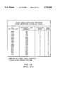
- the exposure table in FIG. 2Bis a sports mode fixed-length exposure table quantized to 0.5 stop (exposure value) increments. In this mode, the exposure time is kept as short as possible to stop motion, while aperture and gain are manipulated to increase light intensity and signal level.
- Prior art fixed-length exposure tablesare quantized using a particular light level quantization, such as logarithmic luminance quantizing steps, for example 0.5 stop (exposure value) as shown in FIG. 2B.
- the tablesmay be quantized in erratic ways, or may be excessively large, depending on the light level quantization chosen.
- upwards of twenty tablesmay be used to cover different operating modes and different focal lengths (for zoom cameras). Such problems can cause the deterioration of image quality in certain situations, as well as requiring relatively large memory to store the tables.
- a photographic cameraincludes a photosensitive image receiver for generating an image, an optical system for focusing incident light representative of the image upon the receiver, and an exposure level determination section responsive to the incident light for generating a measured exposure value.
- the cameraincludes an exposure table containing values that regulate at least one photographic attribute that controls the image.
- the tableincludes a sequence of table entries for exposure values and corresponding values of at least one of an optical aperture value and an electronic gain value that provide for each table entry a correct image exposure for the corresponding exposure value, wherein the sequence of table entries are selected such that increments between the exposure values represented in the table are variable in length, thereby providing a continuous series of said at least one of the optical aperture values and gain values represented in the table.
- variable-length exposure tablesrather than fixed-length tables
- the technical advantage of the inventionis realized, that is, the tables can be tailored to provide optimum image quality while minimizing the size of memory needed to store the tables.
- FIG. 1shows FIGS. 1A and 1B which show a table for converting light level and receiver speed into an exposure value
- FIGS. 2A and 2Bare examples of known, fixed-length exposure tables
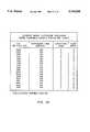
- FIGS. 3A and 3Bare illustrations of variable-length exposure tables according to the invention.
- FIG. 4shows FIGS. 4A and 4B which show a block diagram of an electronic camera incorporating a variable-length exposure table of the type shown in FIGS. 3A or 3B;
- FIG. 5is an example of another known fixed-length exposure table, this one for fill-flash.
- FIG. 6is the variable length analog to the fixed length table of FIG. 6.
- the inventionis embodied in an exposure table of variable length, such as shown in FIGS. 3A and 3B, which contains all of the exact switch points, in terms of exposure values, at which the acquisition parameters for aperture and gain change.
- These tablesare the variable length analogs to the fixed length tables in FIGS. 2A and 2B.
- the exposure timeis not actually stored, but calculated at runtime.
- the exposure valuesare stored, although there may be fewer than in the number implied by the fixed-length tables.
- the quantization increments on the switch points for the acquisition parametersthe number of entries may drop, but more importantly the table contains more accurate information for the exact switch points. This can be better understood by referring to an example, as follows.
- the fixed-length table(FIG. 2A) would yield due to quantization an aperture step of 2 and a gain step of 7, while the corresponding variable-length table (FIG. 3A) would yield an aperture step of 3 and a gain step of 7.
- the aperturecould be set to a smaller value (as provided by the variable-length table), than provided by the fixed-length table. This is because the fixed-length table rounds down to the 9.5 entry settings, rather than down to the nearest switch-point values of 9.65, as is done in the variable-length table.
- the exposure timemight in fact be manipulated to generate the correct exposure, but the exposure time could actually be forced to increase past the bounds for acceptable image blur.
- the camerahas more gain or aperture steps available, and can utilize them to better advantage in certain situations without, for example, having to increase the exposure time beyond acceptable bounds.
- aperture stepstypically refer to incremental aperture diameters.
- the exposure control systemwill set the aperture to its largest diameter, while an output of 5 means the smallest available aperture diameter.
- FocalLengthfocal length of the lens in mm
- ApertureDiameterdiameter of the aperture opening in mm
- Pupil Magaperture diameter magnification going through camera lens
- Gain stepsin an electronic camera, refers to setting the analog gain between the image sensor and the digital conversion step. When set to higher values, the signal coming out of the image sensor is amplified, along with any noise. Although raising the gain allows the exposure time or aperture diameter to stay as small as possible, the amplification of the noise from the image sensor may result in grainy images, similar to using faster speed film.
- Practice of the inventionin this case, allows use of a continuous series, or range of gain factors. Other gain factors may be achievable, of course, but are not useful in the system (e.g., because of noise) and therefore are not in the table. Similarly, some apertures may be achievable but not useful, for example, because of optical aberrations. Practice of the invention, in this case, allows use of a continuous series, or range of useful aperture values.
- FIG. 4A block diagram of a photographic camera incorporating a variable length exposure table according to the invention is shown in FIG. 4.
- Incident light from an objectis focused upon a photosensitive image receiver by an optical system, in this case including a motor driven zoom lens 12 and a mechanical aperture 14.
- the camera shown in FIG. 4is an electronic camera and the photosensitive image receiver is an electronic image sensor 10.
- the intensity of the image light upon the sensor 10, which may be influenced by a flash 11,is regulated by the motor-driven, mechanical aperture 14, while exposure time is regulated electronically by appropriate clocking of the sensor 10.
- the still image from the image sensor 10is processed in an analog processing section 16, converted to a digital signal, arid digitally stored on a removable memory card 18.
- Control of the sensoris provided by a timing and control section 20, which provides processing and timing functions for the camera.
- the timing and control section 20includes a sensor timing circuit 22 for controlling the image sensor functions.
- the sensor timing circuit 22provides the signals to enable sensor drivers 24, which provide horizontal clocks (H1, H2), and vertical clocks (V1, V2).
- the output of the image sensor 10is amplified and processed in an analog programmable gain setting circuit 26, then sampled in a correlated double sampling (CDS) circuit 28, and converted to digital form in A/D converter stage 30.
- the gain setting circuit 26is responsive to an electronic gain value for establishing the gain of the signal output by the image sensor 10.
- the A/D output signalis provided through a high speed interface 31 to a processor section 32, which includes a digital processor 34, a DFAM memory 36 for temporarily storing the still images, and a firmware memory 38.
- the digital processor 32performs image processing on the still images, and stores the processed images on the removable memory card 18 via a memory card interface circuit 40, which may use the PCMCIA 2.0 standard interface.
- the EPROM firmware memory 38is used to store the firmware which operates the processor 34.
- the components of the processor section 34are interconnected through a data bus 42, which also connects to the timing and control section 20 and to the card interface 40.
- the motor-driven zoom lens 12includes a zoom motor 44, a focus motor 46, and an aperture motor 48 (all controlled by respective motor drivers 44', 46', 48').
- the timing and control section 20further includes an exposure control interface 50, which is connected to the aperture motor driver 48', a flash control circuit 52(which controls the operation of the flash 11), the sensor timing circuit 22, and the programmable gain setting circuit 26.
- Exposure levelis input to the exposure control interface 50 by an exposure level determination circuit 54, and the exposure tables are accessed from the exposure table memory 56.
- a capture switch 56ais used to trigger a capture sequence for taking and recording an image
- exposure mode user switches 56bare used to select an exposure mode, e.g., fill flash, sports, portrait, landscape, and so on.
- Each exposure modecorresponds to a particular exposure table in the exposure table memory 56.
- the lens zoom positionis controlled by a zoom lens controller 60 based on position input from the zoom control switches 62 (providing, for instance, separate "zoom in” and “zoom out” buttons).
- the focusing values and exposure valuesare computed automatically by an image statistics processor 64 in the timing and control section 20 as image data is read out of the image sensor 10. More specifically, the image statistics processor 64 computes focus values which are then used to adjust the focus motor 46' via a focus control interface 65.
- the image statistics processor 64also provides a light value reading determined from the image data originating from the image sensor 10. This light value reading, which corresponds to the footlamberts entry in FIG. 1, is then converted into an exposure value in the exposure level determination circuit 54.
- a dedicated exposure sensor 63may input a light reading directly to the exposure level determination circuit 54 for conversion into an exposure value. This exposure value is then used to dereference a selected exposure table stored in the exposure table memory 56.
- the sensor 10is a progressive scan interline color image sensor having a noninterlaced architecture. It comprises a two-dimensional array of photosites 66, e.g. photodiodes, overlain by a color filter array and arranged in rows and columns of image pixels. A plurality of vertical registers 68 adjacent photosite columns are arranged to transfer rows of image pixel charge from the photosites 66 to a horizontal register 70 for readout responsive to clock signals from the sensor drivers 24.
- a preferred image sensoris the Kodak model CCD KAI-0400CM image sensor, which has approximately 512 active lines with approximately 768 active pixels per line and an image aspect ratio of 3:2. This sensor is described in a Performance Specification document available from Eastman Kodak Company, Rochester, N.Y.
- the sensor 20uses a progressive scan readout method, which allows the entire image to be read out in a single scan.
- the accumulated or integrated charge for the photodiodes comprising the pixels 66is transported from the photosites to the light protected vertical (parallel) registers 68 by applying a large positive voltage to the phase-one vertical clock (V1). This reads out every row, or line, into the vertical registers 68.
- the image pixel chargeis then transported from the vertical registers 68 to the horizontal register 70 by two-phase clocking of the vertical clocks (V1, V2).
- the horizontal register 70delivers a stream of color pixel signals to the analog processing section 16.
- the color pixel signalsare subsequently converted to digital pixel signals in the A/D converter 30.
- the userturns on the camera (using a power switch (not shown), which may be automatically enabled when the user depresses the zoom switches 62, or partially depresses the capture button 56a).
- the userselects different exposure modes (e.g., a sports mode, a landscape mode, a portrait mode, etc.) by activating the appropriate exposure mode switch 56b.
- the exposure mode switch 56bthat has been activated, the selected exposure table 56 is accessed by the exposure control interface 50.
- the exposure level determination circuit 54receives a current light level measurement from either the external light metering unit 63 (as in a film camera) or from the image sensor 10 itself (as in an electronic camera).
- the external light meter outputdirectly describes the scene light level.
- the current acquisition parameters and the current image levelsare used to calculate an effective scene light level.
- This light levelis converted to exposure value and used by the exposure control interface 50 to reference the selected exposure table, which describes the acquisition parameter settings to be used to correctly expose the image receiver for this incident light level.
- the exposure control interface 50applies the appropriate signals to modify the aperture diameter, the analog gain, and/or the exposure time to correctly capture an image. Exposure on the image receiver will increase if the exposure control interface 50 increases the aperture diameter or the exposure time. Exposure will decrease by decreasing the aperture diameter or the exposure time.
- the aperture diameter, exposure time and gainare specified by the step increments used by the system, such as the stepper motor steps used by the motor 48 to set the aperture position.
- the exposure time stepscontrol either a mechanical or electronic shutter for either electronic or film camera applications.
- One time unitfor example, represent the minimum exposure time possible, such as one scanning line time or approximately 50 microseconds.
- the time stepwould control a hardware counter mechanism which counts at the time step quantization.
- 10 exposure stepswould yield an exposure time of 10 times the hardware exposure time quantization, for example, 500 microseconds.
- Gaincan be increased to increase the signal from the electronic image sensor 10 before it is quantized by the system A/D converter 30.
- the usercomposes the picture by depressing the "zoom in” or “zoom out” switches 64, and by adjusting the position of the camera, while observing the image through an interconnected viewfinder (not shown).
- the userdepresses the capture button 56a, which initiates the capture sequence.
- the cameracaptures a single still image, firing the flash 11 if necessary when the ambient illumination level is low.
- FIG. 5 and 6show examples of fixed length and variable length fill flash mode exposure tables, respectively.
- the flashis always turned on (flash charge-255) but turned off at variable times (according to the flash discharge columns).
- the variable length table(FIG. 6) shows a considerable saving of memory compared to the fixed length table (FIG. 5).
Landscapes
- Engineering & Computer Science (AREA)
- Multimedia (AREA)
- Signal Processing (AREA)
- Physics & Mathematics (AREA)
- General Physics & Mathematics (AREA)
- Studio Devices (AREA)
- Exposure Control For Cameras (AREA)
Abstract
Description
Effective F-number=Focal Length/(ApertureDiameter*Pupil Mag)
Claims (17)
Priority Applications (1)
| Application Number | Priority Date | Filing Date | Title |
|---|---|---|---|
| US08/565,371US5745808A (en) | 1995-08-21 | 1995-11-30 | Camera exposure control system using variable-length exposure tables |
Applications Claiming Priority (2)
| Application Number | Priority Date | Filing Date | Title |
|---|---|---|---|
| US257295P | 1995-08-21 | 1995-08-21 | |
| US08/565,371US5745808A (en) | 1995-08-21 | 1995-11-30 | Camera exposure control system using variable-length exposure tables |
Publications (1)
| Publication Number | Publication Date |
|---|---|
| US5745808Atrue US5745808A (en) | 1998-04-28 |
Family
ID=26670567
Family Applications (1)
| Application Number | Title | Priority Date | Filing Date |
|---|---|---|---|
| US08/565,371Expired - LifetimeUS5745808A (en) | 1995-08-21 | 1995-11-30 | Camera exposure control system using variable-length exposure tables |
Country Status (1)
| Country | Link |
|---|---|
| US (1) | US5745808A (en) |
Cited By (42)
| Publication number | Priority date | Publication date | Assignee | Title |
|---|---|---|---|---|
| US5862420A (en)* | 1996-09-25 | 1999-01-19 | Seiko Precision Inc. | Control device for a camera shutter and a control method therefor |
| US6100928A (en)* | 1996-07-19 | 2000-08-08 | Ricoh Company, Ltd. | Digital camera with variable gain to offset exposure error |
| US6108032A (en)* | 1996-11-05 | 2000-08-22 | Lockheed Martin Fairchild Systems | System and method for image motion compensation of a CCD image sensor |
| US6163816A (en)* | 1997-08-29 | 2000-12-19 | Flashpoint Technology, Inc. | System and method for retrieving capability parameters in an electronic imaging device |
| US6256057B1 (en)* | 1996-11-05 | 2001-07-03 | Lockhead Martin Corporation | Electro-optical reconnaissance system with forward motion compensation |
| US20020012065A1 (en)* | 2000-04-27 | 2002-01-31 | Ricoh Company, Ltd | Exposure control apparatus and method thereof |
| US6486915B2 (en)* | 1999-04-20 | 2002-11-26 | Intel Corporation | Determining a final exposure setting automatically for a solid state camera without a separate light metering circuit |
| US6621987B1 (en)* | 2003-01-29 | 2003-09-16 | Novatek Microelectronics Corp. | Method of fast converging appropriate exposure value |
| US20030184673A1 (en)* | 2002-04-02 | 2003-10-02 | Michael Skow | Automatic exposure control for digital imaging |
| US20030223010A1 (en)* | 2002-06-04 | 2003-12-04 | Michael Kaplinsky | Method and apparatus for automatic gain and exposure control for maintaining target image brightness in video imager systems |
| US6667765B1 (en)* | 1998-08-06 | 2003-12-23 | Minolta Co., Ltd. | Image pickup apparatus |
| US6700619B1 (en)* | 1997-05-20 | 2004-03-02 | Minolta Co., Ltd. | Electronic still camera with feedback control |
| US20040051790A1 (en)* | 2002-06-24 | 2004-03-18 | Masaya Tamaru | Image pickup apparatus and image processing method |
| US20040201771A1 (en)* | 2003-04-14 | 2004-10-14 | Fuji Photo Film Co., Ltd. | Image-taking apparatus and image-taking method |
| US20050156871A1 (en)* | 2003-12-30 | 2005-07-21 | Texas Instruments Incorporated | Automatic gain control for image display systems |
| US6999123B1 (en)* | 1998-10-27 | 2006-02-14 | Sanyo Electric Co., Ltd. | Method and apparatus for driving solid state image sensor |
| US7053954B1 (en)* | 1998-10-23 | 2006-05-30 | Datalogic S.P.A. | Process for regulating the exposure time of a light sensor |
| US20060262215A1 (en)* | 2005-05-18 | 2006-11-23 | Mei-Chuan Wang | Auto-exposing method of a digital photographic apparatus |
| US20070126922A1 (en)* | 2005-11-28 | 2007-06-07 | Stmicroelectronics (Research & Development) Limited | Method and apparatus for exposure level setting in machine vision systems |
| US20070166020A1 (en)* | 2006-01-19 | 2007-07-19 | Shuxue Quan | Hand jitter reduction system for cameras |
| US20070205935A1 (en)* | 1999-07-12 | 2007-09-06 | Jun Koyama | Digital driver and display device |
| CN100337156C (en)* | 2002-12-05 | 2007-09-12 | 联咏科技股份有限公司 | Fast Convergence Method for Appropriate Exposure Values |
| WO2008039551A1 (en)* | 2006-09-25 | 2008-04-03 | Qualcomm Incorporated | A hand jitter reduction system for cameras |
| US20080252741A1 (en)* | 2007-04-10 | 2008-10-16 | Takashi Kameyama | Imaging apparatus and imaging method |
| US20090278964A1 (en)* | 2004-10-19 | 2009-11-12 | Mcgarvey James E | Method and apparatus for capturing high quality long exposure images with a digital camera |
| US20100134650A1 (en)* | 2008-12-01 | 2010-06-03 | Samsung Electro-Mechanics Co. Ltd. | Method for controlling auto-exposure |
| US20100151903A1 (en)* | 2008-12-17 | 2010-06-17 | Sony Ericsson Mobile Communications Japan, Inc. | Mobile phone terminal with camera function and control method thereof |
| US7970239B2 (en) | 2006-01-19 | 2011-06-28 | Qualcomm Incorporated | Hand jitter reduction compensating for rotational motion |
| US8019179B2 (en) | 2006-01-19 | 2011-09-13 | Qualcomm Incorporated | Hand jitter reduction for compensating for linear displacement |
| US8102457B1 (en) | 1997-07-09 | 2012-01-24 | Flashpoint Technology, Inc. | Method and apparatus for correcting aspect ratio in a camera graphical user interface |
| US8127232B2 (en) | 1998-12-31 | 2012-02-28 | Flashpoint Technology, Inc. | Method and apparatus for editing heterogeneous media objects in a digital imaging device |
| US20120169886A1 (en)* | 2010-12-31 | 2012-07-05 | Hon Hai Precision Industry Co., Ltd. | System and method for testing aperture of image capturing device |
| US20150042758A1 (en)* | 2013-08-09 | 2015-02-12 | Makerbot Industries, Llc | Laser scanning systems and methods |
| DE102014102080A1 (en) | 2014-02-19 | 2015-08-20 | Carl Zeiss Ag | Method for image acquisition and image acquisition system |
| US9224145B1 (en) | 2006-08-30 | 2015-12-29 | Qurio Holdings, Inc. | Venue based digital rights using capture device with digital watermarking capability |
| US20160188831A1 (en)* | 2007-05-22 | 2016-06-30 | Intellectual Ventures Fund 83 Llc | Capturing data for individual physiological monitoring |
| US20190253601A1 (en)* | 2016-10-26 | 2019-08-15 | Zhejiang Dahua Technology Co., Ltd. | Systems and methods for exposure control |
| US10721409B2 (en) | 2016-12-27 | 2020-07-21 | Zhejiang Dahua Technology Co., Ltd. | Systems and methods for exposure control |
| CN113660413A (en)* | 2021-07-26 | 2021-11-16 | 中国科学院西安光学精密机械研究所 | Automatic exposure method for large-caliber large-view-field camera applied to aircraft |
| US11194227B2 (en) | 2016-12-27 | 2021-12-07 | Zhejiang Dahua Technology Co., Ltd. | Systems and methods for exposure control |
| US11265459B2 (en) | 2017-09-01 | 2022-03-01 | Samsung Electronics Co., Ltd. | Electronic device and control method therefor |
| US20220174201A1 (en)* | 2020-11-30 | 2022-06-02 | Canon Kabushiki Kaisha | Apparatus, method for controlling apparatus, and storage medium |
Citations (10)
| Publication number | Priority date | Publication date | Assignee | Title |
|---|---|---|---|---|
| US4884144A (en)* | 1986-05-21 | 1989-11-28 | Canon Kabushiki Kaisha | Electronic camera |
| US4903136A (en)* | 1987-08-31 | 1990-02-20 | Asahi Kogaku Kogyo K.K. | Automatic sensitivity controller for electronic still camera |
| US4953029A (en)* | 1986-11-29 | 1990-08-28 | Minolta Camera Kabushiki Kaisha | Interchangeable film back or still video back still camera system |
| US4969045A (en)* | 1988-05-20 | 1990-11-06 | Sanyo Electric Co., Ltd. | Image sensing apparatus having automatic iris function of automatically adjusting exposure in response to video signal |
| US5017955A (en)* | 1989-01-18 | 1991-05-21 | Fuji Photo Film Co., Ltd. | Autofocus camera with flash unit |
| US5079622A (en)* | 1988-01-12 | 1992-01-07 | Sanyo Electric Co., Ltd. | Auto iris/gamma correction apparatus for making automatic exposure adjustment and/or automatic gamma correction in response to video signal and image sensing apparatus comprising such auto iris/gamma correction apparatus |
| US5115319A (en)* | 1989-12-08 | 1992-05-19 | Fuji Photo Film Co., Ltd. | Automatic exposure control apparatus and method for electronic still camera |
| US5258848A (en)* | 1991-02-28 | 1993-11-02 | Sony Corporation | Exposure controller of a video camera |
| US5315394A (en)* | 1990-09-04 | 1994-05-24 | Hitachi, Ltd. | Auto-iris method and apparatus for imaging device |
| US5606392A (en)* | 1996-06-28 | 1997-02-25 | Eastman Kodak Company | Camera using calibrated aperture settings for exposure control |
- 1995
- 1995-11-30USUS08/565,371patent/US5745808A/ennot_activeExpired - Lifetime
Patent Citations (10)
| Publication number | Priority date | Publication date | Assignee | Title |
|---|---|---|---|---|
| US4884144A (en)* | 1986-05-21 | 1989-11-28 | Canon Kabushiki Kaisha | Electronic camera |
| US4953029A (en)* | 1986-11-29 | 1990-08-28 | Minolta Camera Kabushiki Kaisha | Interchangeable film back or still video back still camera system |
| US4903136A (en)* | 1987-08-31 | 1990-02-20 | Asahi Kogaku Kogyo K.K. | Automatic sensitivity controller for electronic still camera |
| US5079622A (en)* | 1988-01-12 | 1992-01-07 | Sanyo Electric Co., Ltd. | Auto iris/gamma correction apparatus for making automatic exposure adjustment and/or automatic gamma correction in response to video signal and image sensing apparatus comprising such auto iris/gamma correction apparatus |
| US4969045A (en)* | 1988-05-20 | 1990-11-06 | Sanyo Electric Co., Ltd. | Image sensing apparatus having automatic iris function of automatically adjusting exposure in response to video signal |
| US5017955A (en)* | 1989-01-18 | 1991-05-21 | Fuji Photo Film Co., Ltd. | Autofocus camera with flash unit |
| US5115319A (en)* | 1989-12-08 | 1992-05-19 | Fuji Photo Film Co., Ltd. | Automatic exposure control apparatus and method for electronic still camera |
| US5315394A (en)* | 1990-09-04 | 1994-05-24 | Hitachi, Ltd. | Auto-iris method and apparatus for imaging device |
| US5258848A (en)* | 1991-02-28 | 1993-11-02 | Sony Corporation | Exposure controller of a video camera |
| US5606392A (en)* | 1996-06-28 | 1997-02-25 | Eastman Kodak Company | Camera using calibrated aperture settings for exposure control |
Cited By (71)
| Publication number | Priority date | Publication date | Assignee | Title |
|---|---|---|---|---|
| US6100928A (en)* | 1996-07-19 | 2000-08-08 | Ricoh Company, Ltd. | Digital camera with variable gain to offset exposure error |
| US5862420A (en)* | 1996-09-25 | 1999-01-19 | Seiko Precision Inc. | Control device for a camera shutter and a control method therefor |
| US6108032A (en)* | 1996-11-05 | 2000-08-22 | Lockheed Martin Fairchild Systems | System and method for image motion compensation of a CCD image sensor |
| US6256057B1 (en)* | 1996-11-05 | 2001-07-03 | Lockhead Martin Corporation | Electro-optical reconnaissance system with forward motion compensation |
| US6373522B2 (en)* | 1996-11-05 | 2002-04-16 | Bae Systems Information And Electronic Systems Integration Inc. | Electro-optical reconnaissance system with forward motion compensation |
| US6700619B1 (en)* | 1997-05-20 | 2004-03-02 | Minolta Co., Ltd. | Electronic still camera with feedback control |
| US8102457B1 (en) | 1997-07-09 | 2012-01-24 | Flashpoint Technology, Inc. | Method and apparatus for correcting aspect ratio in a camera graphical user interface |
| US8970761B2 (en) | 1997-07-09 | 2015-03-03 | Flashpoint Technology, Inc. | Method and apparatus for correcting aspect ratio in a camera graphical user interface |
| US6163816A (en)* | 1997-08-29 | 2000-12-19 | Flashpoint Technology, Inc. | System and method for retrieving capability parameters in an electronic imaging device |
| US6667765B1 (en)* | 1998-08-06 | 2003-12-23 | Minolta Co., Ltd. | Image pickup apparatus |
| US7053954B1 (en)* | 1998-10-23 | 2006-05-30 | Datalogic S.P.A. | Process for regulating the exposure time of a light sensor |
| US6999123B1 (en)* | 1998-10-27 | 2006-02-14 | Sanyo Electric Co., Ltd. | Method and apparatus for driving solid state image sensor |
| US8127232B2 (en) | 1998-12-31 | 2012-02-28 | Flashpoint Technology, Inc. | Method and apparatus for editing heterogeneous media objects in a digital imaging device |
| US8972867B1 (en) | 1998-12-31 | 2015-03-03 | Flashpoint Technology, Inc. | Method and apparatus for editing heterogeneous media objects in a digital imaging device |
| US9232149B2 (en) | 1999-04-20 | 2016-01-05 | Intel Corporation | Determining a final exposure setting automatically for a solid state camera without a separate light metering circuit |
| US7817206B2 (en) | 1999-04-20 | 2010-10-19 | Intel Corporation | Determining a final exposure setting automatically for a solid state camera without a separate light metering circuit |
| US6486915B2 (en)* | 1999-04-20 | 2002-11-26 | Intel Corporation | Determining a final exposure setting automatically for a solid state camera without a separate light metering circuit |
| US20030122939A1 (en)* | 1999-04-20 | 2003-07-03 | Bell Cynthia S. | Determining a final exposure setting automatically for a solid state camera without a separate light metering circuit |
| US20100315531A1 (en)* | 1999-04-20 | 2010-12-16 | Intel Corporation | Determining a final exposure setting automatically for a solid state camera without a separate light metering circuit |
| US8767091B2 (en) | 1999-04-20 | 2014-07-01 | Intel Corporation | Determining a final exposure setting automatically for a solid state camera without a separate light metering circuit |
| US7403222B2 (en)* | 1999-04-20 | 2008-07-22 | Intel Corporation | Determining a final exposure setting automatically for a sold state camera without a separate light metering circuit |
| US8031262B2 (en) | 1999-04-20 | 2011-10-04 | Intel Corporation | Determining a final exposure setting automatically for a solid state camera without a separate light metering circuit |
| US7375668B2 (en)* | 1999-07-12 | 2008-05-20 | Semiconductor Energy Laboratory Co., Ltd. | Digital driver and display device |
| US20070205935A1 (en)* | 1999-07-12 | 2007-09-06 | Jun Koyama | Digital driver and display device |
| US7023484B2 (en)* | 2000-04-27 | 2006-04-04 | Ricoh Company, Ltd. | Exposure control apparatus and method thereof |
| US20020012065A1 (en)* | 2000-04-27 | 2002-01-31 | Ricoh Company, Ltd | Exposure control apparatus and method thereof |
| US20030184673A1 (en)* | 2002-04-02 | 2003-10-02 | Michael Skow | Automatic exposure control for digital imaging |
| US7245320B2 (en)* | 2002-06-04 | 2007-07-17 | Micron Technology, Inc. | Method and apparatus for automatic gain and exposure control for maintaining target image brightness in video imager systems |
| US20060268136A1 (en)* | 2002-06-04 | 2006-11-30 | Michael Kaplinsky | Method and apparatus for automatic gain and exposure control for maintaining target image brightness in video imager systems |
| US20030223010A1 (en)* | 2002-06-04 | 2003-12-04 | Michael Kaplinsky | Method and apparatus for automatic gain and exposure control for maintaining target image brightness in video imager systems |
| US7755677B2 (en) | 2002-06-04 | 2010-07-13 | Aptina Imaging Corporation | Method and apparatus for automatic gain and exposure control for maintaining target image brightness in video imager systems |
| US20040051790A1 (en)* | 2002-06-24 | 2004-03-18 | Masaya Tamaru | Image pickup apparatus and image processing method |
| US7508421B2 (en)* | 2002-06-24 | 2009-03-24 | Fujifilm Corporation | Image pickup apparatus and image processing method |
| CN100337156C (en)* | 2002-12-05 | 2007-09-12 | 联咏科技股份有限公司 | Fast Convergence Method for Appropriate Exposure Values |
| US6621987B1 (en)* | 2003-01-29 | 2003-09-16 | Novatek Microelectronics Corp. | Method of fast converging appropriate exposure value |
| US20040201771A1 (en)* | 2003-04-14 | 2004-10-14 | Fuji Photo Film Co., Ltd. | Image-taking apparatus and image-taking method |
| US20050156871A1 (en)* | 2003-12-30 | 2005-07-21 | Texas Instruments Incorporated | Automatic gain control for image display systems |
| US7852402B2 (en)* | 2004-10-19 | 2010-12-14 | Eastman Kodak Company | Method and apparatus for capturing high quality long exposure images with a digital camera |
| US20090278964A1 (en)* | 2004-10-19 | 2009-11-12 | Mcgarvey James E | Method and apparatus for capturing high quality long exposure images with a digital camera |
| US20060262215A1 (en)* | 2005-05-18 | 2006-11-23 | Mei-Chuan Wang | Auto-exposing method of a digital photographic apparatus |
| US8477222B2 (en)* | 2005-11-28 | 2013-07-02 | STMicroelectronics (R&D) Ltd. | Method and apparatus for exposure level setting in machine vision systems |
| US20070126922A1 (en)* | 2005-11-28 | 2007-06-07 | Stmicroelectronics (Research & Development) Limited | Method and apparatus for exposure level setting in machine vision systems |
| US8019179B2 (en) | 2006-01-19 | 2011-09-13 | Qualcomm Incorporated | Hand jitter reduction for compensating for linear displacement |
| US7970239B2 (en) | 2006-01-19 | 2011-06-28 | Qualcomm Incorporated | Hand jitter reduction compensating for rotational motion |
| US8120658B2 (en)* | 2006-01-19 | 2012-02-21 | Qualcomm Incorporated | Hand jitter reduction system for cameras |
| US20070166020A1 (en)* | 2006-01-19 | 2007-07-19 | Shuxue Quan | Hand jitter reduction system for cameras |
| US9224145B1 (en) | 2006-08-30 | 2015-12-29 | Qurio Holdings, Inc. | Venue based digital rights using capture device with digital watermarking capability |
| CN101518054B (en)* | 2006-09-25 | 2012-11-21 | 高通股份有限公司 | A hand jitter reduction system for cameras |
| WO2008039551A1 (en)* | 2006-09-25 | 2008-04-03 | Qualcomm Incorporated | A hand jitter reduction system for cameras |
| US8325246B2 (en) | 2007-04-10 | 2012-12-04 | Sony Corporation | Imaging apparatus and imaging method capable of imaging at a low frame rate |
| US20080252741A1 (en)* | 2007-04-10 | 2008-10-16 | Takashi Kameyama | Imaging apparatus and imaging method |
| EP1981266A3 (en)* | 2007-04-10 | 2012-02-29 | Sony Corporation | Imaging apparatus and method |
| US20160188831A1 (en)* | 2007-05-22 | 2016-06-30 | Intellectual Ventures Fund 83 Llc | Capturing data for individual physiological monitoring |
| US10192033B2 (en)* | 2007-05-22 | 2019-01-29 | Monument Peak Ventures, Llc | Capturing data for individual physiological monitoring |
| US20100134650A1 (en)* | 2008-12-01 | 2010-06-03 | Samsung Electro-Mechanics Co. Ltd. | Method for controlling auto-exposure |
| US8115859B2 (en)* | 2008-12-01 | 2012-02-14 | Samsung Electro-Mechanics Co., Ltd. | Method for controlling auto-exposure |
| US8704906B2 (en)* | 2008-12-17 | 2014-04-22 | Sony Corporation | Mobile phone terminal with camera function and control method thereof for fast image capturing |
| US20100151903A1 (en)* | 2008-12-17 | 2010-06-17 | Sony Ericsson Mobile Communications Japan, Inc. | Mobile phone terminal with camera function and control method thereof |
| US20120169886A1 (en)* | 2010-12-31 | 2012-07-05 | Hon Hai Precision Industry Co., Ltd. | System and method for testing aperture of image capturing device |
| US20150042758A1 (en)* | 2013-08-09 | 2015-02-12 | Makerbot Industries, Llc | Laser scanning systems and methods |
| DE102014102080A1 (en) | 2014-02-19 | 2015-08-20 | Carl Zeiss Ag | Method for image acquisition and image acquisition system |
| US20190253601A1 (en)* | 2016-10-26 | 2019-08-15 | Zhejiang Dahua Technology Co., Ltd. | Systems and methods for exposure control |
| US10924684B2 (en)* | 2016-10-26 | 2021-02-16 | Zhejiang Dahua Technology Co., Ltd. | Systems and methods for exposure control |
| US11539897B2 (en) | 2016-10-26 | 2022-12-27 | Zhejiang Dahua Technology Co., Ltd. | Systems and methods for exposure control |
| US10721409B2 (en) | 2016-12-27 | 2020-07-21 | Zhejiang Dahua Technology Co., Ltd. | Systems and methods for exposure control |
| US11194227B2 (en) | 2016-12-27 | 2021-12-07 | Zhejiang Dahua Technology Co., Ltd. | Systems and methods for exposure control |
| US11265459B2 (en) | 2017-09-01 | 2022-03-01 | Samsung Electronics Co., Ltd. | Electronic device and control method therefor |
| US20220174201A1 (en)* | 2020-11-30 | 2022-06-02 | Canon Kabushiki Kaisha | Apparatus, method for controlling apparatus, and storage medium |
| US11678060B2 (en)* | 2020-11-30 | 2023-06-13 | Canon Kabushiki Kaisha | Apparatus, method for controlling apparatus, and storage medium |
| CN113660413A (en)* | 2021-07-26 | 2021-11-16 | 中国科学院西安光学精密机械研究所 | Automatic exposure method for large-caliber large-view-field camera applied to aircraft |
| CN113660413B (en)* | 2021-07-26 | 2022-05-10 | 中国科学院西安光学精密机械研究所 | Automatic exposure method for large-caliber large-view-field camera applied to aircraft |
Similar Documents
| Publication | Publication Date | Title |
|---|---|---|
| US5745808A (en) | Camera exposure control system using variable-length exposure tables | |
| CN100474894C (en) | Electronic blur correction device and electronic blur correction method | |
| US5610654A (en) | Automatic camera exposure control using variable exposure index CCD sensor | |
| US5335075A (en) | Image sensing apparatus having exposure level and dynamic range control circuit | |
| US8619156B2 (en) | Image capturing system and method of controlling the same utilizing exposure control that captures multiple images of different spatial resolutions | |
| US7965334B2 (en) | Auto-focus camera with adjustable lens movement pitch | |
| US7664382B2 (en) | Electronic blur correction device and electronic blur correction method | |
| US20070139548A1 (en) | Image capturing apparatus, image capturing method, and computer-readable medium storing program | |
| US7944501B2 (en) | Image sensing apparatus and image sensing apparatus control method | |
| US7221394B2 (en) | Digital camera | |
| JP2008187615A (en) | Imaging device, imaging apparatus, control method, and program | |
| US10812704B2 (en) | Focus detection device, method and storage medium, for controlling image sensor operations | |
| JP4834425B2 (en) | IMAGING DEVICE AND IMAGING DEVICE CONTROL METHOD | |
| US7426341B2 (en) | Imaging device | |
| US20010013903A1 (en) | Electronic camera and method for calculating an exposure amount | |
| US8497919B2 (en) | Imaging apparatus and control method thereof for controlling a display of an image and an imaging condition | |
| JP2518942B2 (en) | Electronic still camera automatic exposure device | |
| JP5618765B2 (en) | Imaging apparatus and control method thereof | |
| JP5961058B2 (en) | Imaging apparatus and control method thereof, image processing apparatus and control method thereof | |
| JPH11215432A (en) | Digital camera | |
| KR100213888B1 (en) | Auto-focusing control method for video camera | |
| JPH0787372A (en) | Imaging device | |
| JP2007129751A (en) | Imaging apparatus, imaging method, and program | |
| JP2000350088A (en) | Imaging device and control method thereof | |
| JP2006229627A (en) | Digital camera |
Legal Events
| Date | Code | Title | Description |
|---|---|---|---|
| FEPP | Fee payment procedure | Free format text:PAYOR NUMBER ASSIGNED (ORIGINAL EVENT CODE: ASPN); ENTITY STATUS OF PATENT OWNER: LARGE ENTITY | |
| STCF | Information on status: patent grant | Free format text:PATENTED CASE | |
| FPAY | Fee payment | Year of fee payment:4 | |
| FPAY | Fee payment | Year of fee payment:8 | |
| FPAY | Fee payment | Year of fee payment:12 | |
| AS | Assignment | Owner name:CITICORP NORTH AMERICA, INC., AS AGENT, NEW YORK Free format text:SECURITY INTEREST;ASSIGNORS:EASTMAN KODAK COMPANY;PAKON, INC.;REEL/FRAME:028201/0420 Effective date:20120215 | |
| FEPP | Fee payment procedure | Free format text:PAYER NUMBER DE-ASSIGNED (ORIGINAL EVENT CODE: RMPN); ENTITY STATUS OF PATENT OWNER: LARGE ENTITY Free format text:PAYOR NUMBER ASSIGNED (ORIGINAL EVENT CODE: ASPN); ENTITY STATUS OF PATENT OWNER: LARGE ENTITY | |
| AS | Assignment | Owner name:CREO MANUFACTURING AMERICA LLC, WYOMING Free format text:PATENT RELEASE;ASSIGNORS:CITICORP NORTH AMERICA, INC.;WILMINGTON TRUST, NATIONAL ASSOCIATION;REEL/FRAME:029913/0001 Effective date:20130201 Owner name:LASER-PACIFIC MEDIA CORPORATION, NEW YORK Free format text:PATENT RELEASE;ASSIGNORS:CITICORP NORTH AMERICA, INC.;WILMINGTON TRUST, NATIONAL ASSOCIATION;REEL/FRAME:029913/0001 Effective date:20130201 Owner name:KODAK PHILIPPINES, LTD., NEW YORK Free format text:PATENT RELEASE;ASSIGNORS:CITICORP NORTH AMERICA, INC.;WILMINGTON TRUST, NATIONAL ASSOCIATION;REEL/FRAME:029913/0001 Effective date:20130201 Owner name:QUALEX INC., NORTH CAROLINA Free format text:PATENT RELEASE;ASSIGNORS:CITICORP NORTH AMERICA, INC.;WILMINGTON TRUST, NATIONAL ASSOCIATION;REEL/FRAME:029913/0001 Effective date:20130201 Owner name:NPEC INC., NEW YORK Free format text:PATENT RELEASE;ASSIGNORS:CITICORP NORTH AMERICA, INC.;WILMINGTON TRUST, NATIONAL ASSOCIATION;REEL/FRAME:029913/0001 Effective date:20130201 Owner name:KODAK PORTUGUESA LIMITED, NEW YORK Free format text:PATENT RELEASE;ASSIGNORS:CITICORP NORTH AMERICA, INC.;WILMINGTON TRUST, NATIONAL ASSOCIATION;REEL/FRAME:029913/0001 Effective date:20130201 Owner name:FPC INC., CALIFORNIA Free format text:PATENT RELEASE;ASSIGNORS:CITICORP NORTH AMERICA, INC.;WILMINGTON TRUST, NATIONAL ASSOCIATION;REEL/FRAME:029913/0001 Effective date:20130201 Owner name:FAR EAST DEVELOPMENT LTD., NEW YORK Free format text:PATENT RELEASE;ASSIGNORS:CITICORP NORTH AMERICA, INC.;WILMINGTON TRUST, NATIONAL ASSOCIATION;REEL/FRAME:029913/0001 Effective date:20130201 Owner name:KODAK REALTY, INC., NEW YORK Free format text:PATENT RELEASE;ASSIGNORS:CITICORP NORTH AMERICA, INC.;WILMINGTON TRUST, NATIONAL ASSOCIATION;REEL/FRAME:029913/0001 Effective date:20130201 Owner name:KODAK (NEAR EAST), INC., NEW YORK Free format text:PATENT RELEASE;ASSIGNORS:CITICORP NORTH AMERICA, INC.;WILMINGTON TRUST, NATIONAL ASSOCIATION;REEL/FRAME:029913/0001 Effective date:20130201 Owner name:KODAK AVIATION LEASING LLC, NEW YORK Free format text:PATENT RELEASE;ASSIGNORS:CITICORP NORTH AMERICA, INC.;WILMINGTON TRUST, NATIONAL ASSOCIATION;REEL/FRAME:029913/0001 Effective date:20130201 Owner name:EASTMAN KODAK INTERNATIONAL CAPITAL COMPANY, INC., Free format text:PATENT RELEASE;ASSIGNORS:CITICORP NORTH AMERICA, INC.;WILMINGTON TRUST, NATIONAL ASSOCIATION;REEL/FRAME:029913/0001 Effective date:20130201 Owner name:KODAK AMERICAS, LTD., NEW YORK Free format text:PATENT RELEASE;ASSIGNORS:CITICORP NORTH AMERICA, INC.;WILMINGTON TRUST, NATIONAL ASSOCIATION;REEL/FRAME:029913/0001 Effective date:20130201 Owner name:PAKON, INC., INDIANA Free format text:PATENT RELEASE;ASSIGNORS:CITICORP NORTH AMERICA, INC.;WILMINGTON TRUST, NATIONAL ASSOCIATION;REEL/FRAME:029913/0001 Effective date:20130201 Owner name:EASTMAN KODAK COMPANY, NEW YORK Free format text:PATENT RELEASE;ASSIGNORS:CITICORP NORTH AMERICA, INC.;WILMINGTON TRUST, NATIONAL ASSOCIATION;REEL/FRAME:029913/0001 Effective date:20130201 Owner name:KODAK IMAGING NETWORK, INC., CALIFORNIA Free format text:PATENT RELEASE;ASSIGNORS:CITICORP NORTH AMERICA, INC.;WILMINGTON TRUST, NATIONAL ASSOCIATION;REEL/FRAME:029913/0001 Effective date:20130201 | |
| AS | Assignment | Owner name:INTELLECTUAL VENTURES FUND 83 LLC, NEVADA Free format text:ASSIGNMENT OF ASSIGNORS INTEREST;ASSIGNOR:EASTMAN KODAK COMPANY;REEL/FRAME:030304/0525 Effective date:20130201 | |
| AS | Assignment | Owner name:MONUMENT PEAK VENTURES, LLC, TEXAS Free format text:RELEASE BY SECURED PARTY;ASSIGNOR:INTELLECTUAL VENTURES FUND 83 LLC;REEL/FRAME:064599/0304 Effective date:20230728 |