US5745659A - Versatile scaling of drawings - Google Patents
Versatile scaling of drawingsDownload PDFInfo
- Publication number
- US5745659A US5745659AUS08/641,145US64114596AUS5745659AUS 5745659 AUS5745659 AUS 5745659AUS 64114596 AUS64114596 AUS 64114596AUS 5745659 AUS5745659 AUS 5745659A
- Authority
- US
- United States
- Prior art keywords
- scaling factor
- print media
- printer
- printer driver
- Prior art date
- Legal status (The legal status is an assumption and is not a legal conclusion. Google has not performed a legal analysis and makes no representation as to the accuracy of the status listed.)
- Expired - Lifetime
Links
Images


Classifications
- G—PHYSICS
- G06—COMPUTING OR CALCULATING; COUNTING
- G06T—IMAGE DATA PROCESSING OR GENERATION, IN GENERAL
- G06T3/00—Geometric image transformations in the plane of the image
- G06T3/40—Scaling of whole images or parts thereof, e.g. expanding or contracting
- G—PHYSICS
- G06—COMPUTING OR CALCULATING; COUNTING
- G06F—ELECTRIC DIGITAL DATA PROCESSING
- G06F3/00—Input arrangements for transferring data to be processed into a form capable of being handled by the computer; Output arrangements for transferring data from processing unit to output unit, e.g. interface arrangements
- G06F3/12—Digital output to print unit, e.g. line printer, chain printer
- G06F3/1201—Dedicated interfaces to print systems
- G06F3/1202—Dedicated interfaces to print systems specifically adapted to achieve a particular effect
- G06F3/1203—Improving or facilitating administration, e.g. print management
- G06F3/1208—Improving or facilitating administration, e.g. print management resulting in improved quality of the output result, e.g. print layout, colours, workflows, print preview
- G—PHYSICS
- G06—COMPUTING OR CALCULATING; COUNTING
- G06F—ELECTRIC DIGITAL DATA PROCESSING
- G06F3/00—Input arrangements for transferring data to be processed into a form capable of being handled by the computer; Output arrangements for transferring data from processing unit to output unit, e.g. interface arrangements
- G06F3/12—Digital output to print unit, e.g. line printer, chain printer
- G06F3/1201—Dedicated interfaces to print systems
- G06F3/1223—Dedicated interfaces to print systems specifically adapted to use a particular technique
- G06F3/1237—Print job management
- G06F3/125—Page layout or assigning input pages onto output media, e.g. imposition
- G06F3/1251—Page layout or assigning input pages onto output media, e.g. imposition for continuous media, e.g. web media, rolls
- G—PHYSICS
- G06—COMPUTING OR CALCULATING; COUNTING
- G06F—ELECTRIC DIGITAL DATA PROCESSING
- G06F3/00—Input arrangements for transferring data to be processed into a form capable of being handled by the computer; Output arrangements for transferring data from processing unit to output unit, e.g. interface arrangements
- G06F3/12—Digital output to print unit, e.g. line printer, chain printer
- G06F3/1201—Dedicated interfaces to print systems
- G06F3/1223—Dedicated interfaces to print systems specifically adapted to use a particular technique
- G06F3/1237—Print job management
- G06F3/1253—Configuration of print job parameters, e.g. using UI at the client
- G06F3/1256—User feedback, e.g. print preview, test print, proofing, pre-flight checks
- G—PHYSICS
- G06—COMPUTING OR CALCULATING; COUNTING
- G06F—ELECTRIC DIGITAL DATA PROCESSING
- G06F3/00—Input arrangements for transferring data to be processed into a form capable of being handled by the computer; Output arrangements for transferring data from processing unit to output unit, e.g. interface arrangements
- G06F3/12—Digital output to print unit, e.g. line printer, chain printer
- G06F3/1201—Dedicated interfaces to print systems
- G06F3/1278—Dedicated interfaces to print systems specifically adapted to adopt a particular infrastructure
- G06F3/1284—Local printer device
- G—PHYSICS
- G06—COMPUTING OR CALCULATING; COUNTING
- G06K—GRAPHICAL DATA READING; PRESENTATION OF DATA; RECORD CARRIERS; HANDLING RECORD CARRIERS
- G06K15/00—Arrangements for producing a permanent visual presentation of the output data, e.g. computer output printers
- G—PHYSICS
- G06—COMPUTING OR CALCULATING; COUNTING
- G06F—ELECTRIC DIGITAL DATA PROCESSING
- G06F3/00—Input arrangements for transferring data to be processed into a form capable of being handled by the computer; Output arrangements for transferring data from processing unit to output unit, e.g. interface arrangements
- G06F3/12—Digital output to print unit, e.g. line printer, chain printer
- G06F3/1201—Dedicated interfaces to print systems
- G06F3/1223—Dedicated interfaces to print systems specifically adapted to use a particular technique
- G06F3/1237—Print job management
- G06F3/1253—Configuration of print job parameters, e.g. using UI at the client
- G06F3/1254—Automatic configuration, e.g. by driver
- G—PHYSICS
- G06—COMPUTING OR CALCULATING; COUNTING
- G06K—GRAPHICAL DATA READING; PRESENTATION OF DATA; RECORD CARRIERS; HANDLING RECORD CARRIERS
- G06K2215/00—Arrangements for producing a permanent visual presentation of the output data
- G06K2215/0002—Handling the output data
- G06K2215/0005—Accepting output data; Preparing data for the controlling system
- G06K2215/0017—Preparing data for the controlling system, e.g. status, memory data
- G—PHYSICS
- G06—COMPUTING OR CALCULATING; COUNTING
- G06K—GRAPHICAL DATA READING; PRESENTATION OF DATA; RECORD CARRIERS; HANDLING RECORD CARRIERS
- G06K2215/00—Arrangements for producing a permanent visual presentation of the output data
- G06K2215/0082—Architecture adapted for a particular function
Definitions
- the present inventionconcerns printing of drawings within a computing system and pertains particularly to the scaling of drawings for printing.
- the present inventionis especially useful to the field of computer driven printers particularly designed for producing engineering or other large drawings on paper, vellum, film or other print media which is drawn through the mechanism from a roll or from a manual or automatic sheet feed media path.
- the mediamay have a width from 81/2 inches to as much as 3 or 4 feet or more.
- the paper or other print mediais drawn through the printer in the X direction and a thermal inkjet printer carriage is mounted for movement transversely of the paper in what shall be referred to as the Y direction.
- a sheet of paper or other print mediais either manually fed or paper is drawn from a supply roll thereof around a platen roller which may or may not be power driven.
- the printer apparatusemploys a thermal inkjet printing head or heads, precise control of the spacing between the print heads and the surface of the print media on which printing is to take place is essential otherwise acceptable print resolution is lost.
- Inkjet printerssuch as those sold by Hewlett Packard Company, offer substantial improvements in speed over the conventional X-Y plotter.
- Inkjet printerstypically include a pen having an array of nozzles. The pens are mounted on a carriage which is moved across the page in successive swaths.
- Each inkjet penhas heater circuits which, when activated, cause ink to be ejected from associated nozzles. As the pen is positioned over a given location, a jet of ink is ejected from the nozzle to provide a pixel of ink at a desired location.
- the mosaic of pixelsthus created provides a desired composite image.
- printers for large print mediaintroduces special problems in printer software.
- many operating systemssuch as the Microsoft Windows operating system, available from Microsoft Corporation having a business address of One Microsoft Way, Redmond, Washington 98052, are currently limited as to the size of papers supported. This limitation has been inherited by applications as either a limited paper size support or as system crashes with big paper sizes.
- GDIgraphic-device interface
- Another way to overcome the size limitations of paper sizesis to report a bigger resolution than the device resolution. In that way the application and the GDI are forced to generate more pixels. However, big scale factors resulting in higher resolutions increase the likelihood that an application will cause the operating system to crash. In addition, there is limit to the amount of pixels which can be handled by the GDI.
- a print preview featureis particularly important for large-sized media printers because the cost of print media and ink can be significant, and reprinting can be costly both in the cost of print media and ink as well as in time spent printing.
- the application print preview featureshows only a very inadequate preview of the drawing to be printed.
- the application print previewmay only show a representation of physical paper and an area within the physical paper on which the printing will take place.
- the application print previewmay show a correct representation of the physical paper without showing if the drawing is going to be clipped because it will be outside of the plotting area.
- a drawing which is calibrated to fit a source print media with a first sizeis scaled to fit a destination print media with a second size.
- a printer driverdetermines a total scaling factor (TSF) by which the drawing is to be scaled in order to fit the destination print media.
- the printer driveralso determines an integer scaling factor (ISF) which is to be used by a printer to scale the drawing before printing the drawing.
- the printer driveradditionally determines a virtual resolution (RES') to be reported to an operating system as the resolution of the printer.
- the virtual resolution (RES')is equal to a true resolution (RES) used by the printer multiplied by a real scale factor (RSF).
- the real scale factoris equal to the total scaling factor divided by the integer scaling factor.
- the printer driverreports the virtual resolution to the operating system.
- the printer driverscales the print output by the integer scaling factor before the print output is sent to the printer.
- the integer scaling factoris determined, for example, by taking the integer nearest the total scaling factor with a value less than the total scaling factor. Alternately, the integer scaling factor is determined by taking the integer nearest the total scaling factor with a value greater than the total scaling factor.
- the total scaling factoris determined by taking the minimum of the height of the destination print media divided by the height of the source print media or the width of the destination print media divided by the width of the source print media.
- the printer drivercenters the output on the destination page.
- the present inventionprovides an efficient way to perform scaling while avoiding rounding errors and minimizing the potential of system crashes.
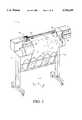
- FIG. 1is a perspective view of a printer/plotter mechanism showing the cover partly broken away to reveal a platen roller, pinch rollers and a print head carriage mounted on slider rods which extend parallel to the axis of the platen roller.
- FIG. 2is right hand cross sectional elevation showing the ends of the platen roller, pinch rollers and mechanism for moving the pinch roller support member into and out of an operative position for the printer/plotter shown in FIG. 1.
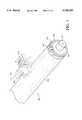
- FIG. 3is a perspective view of the carriage assembly, the carriage positioning mechanism, and the paper positioning mechanism of a printer/plotter similar to the one shown in FIG. 1.
- FIG. 4is perspective view of a simplified representation of a media positioning system utilized in a printer/plotter similar to the one shown in FIG. 1.
- FIG. 5shows a simplified block diagram of the organization of a computing system which includes drivers for a printer and a display in accordance with a preferred embodiment of the present invention.
- FIG. 6, FIG. 7 and FIG. 8show window displays for the computing system shown in FIG. 5, the displays illustrate selection of paper sizes and scaling of output to be printed, in accordance with a preferred embodiment of the present invention.
- FIG. 9shows a window display for the computing system shown in FIG. 5, the display illustrates scaling and the selection of print preview and layout options for output to be printed, in accordance with a preferred embodiment of the present invention.
- FIG. 10shows a window display for the computing system shown in FIG. 5, the display illustrates scaling and the selection of print preview and layout options for output to be printed, in accordance with an alternative preferred embodiment of the present invention.
- FIG. 11, FIG. 12, FIG. 13, FIG. 14 and FIG. 15show window displays for the computing system shown in FIG. 5, the displays illustrate operation of a print preview feature of the computing system, in accordance with a preferred embodiment of the present invention.
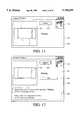
- FIG. 16illustrates the distinctions between page size, margin, plotting area and inked area.
- FIG. 1is a perspective view of a printer/plotter mechanism having a chassis 2 supported by a pair of spaced legs 4 and a housing which includes a generally arcuate cover 6 for containing a roll 7 of print medium such as paper, vellum or film.
- a platen roller 10extends transversely of the apparatus in the Y direction to provide a support and printing path at its upper surface for the medium upon which printing is to take place.
- a pair of slider rodssupport a transversely movable print head carriage 30 having a thermal inkjet print head or a plurality of thermal inkjet print heals mounted thereon which are positioned a precise distance above the platen roller 10.
- the pinch roller support member 25has at least one rearwardly extending upper stabilizer shoulder 28 having an arcuate surface 29 thereon which limits upward motion of the pinch roller support member 25 when it is retracted away from the platen roller 10 by abutment of the surface 29 with one of two printer carriage slider rods 12 mounted on the chassis of the printer/plotter.
- a generally cylindrical support bearingis provided at the rearward end of the support arm 27 and is seen to have a bore 31 in the end thereof which receives one end of a compression spring 32.
- a support bearing 35is mounted on the printer/plotter chassis and has a circular/cylindrical interior surface which receives and supports the support arm 27.
- the inside diameter of the surface of bearing 35is made slightly larger than the outside diameter of the bearing surface on the support arm 27 to permit vertical movement of the arm 27 in the bearing 35 within a selected angular tolerance.
- the distance from the captured end 28 of the support arm 27 to the centerline of the platen roller 10is preferably about twice the distance from the centerline of the pinch rollers to the center of curvature of the arcuate media guide surface 21 which also generally coincides with the centerline of the platen roller 10.
- the compression spring 32thus biases the pinch roller support member 25 and pinch rollers 20 toward the platen roller during printing.
- the pinchroller positionwill shift angularly around the platen roller 10 only about one half the selected angular bearing tolerance because the assembly is constrained to rotate about the center of the platen roller 10.
- the paperWhen it is desired to load a sheet of printing medium into the printer/plotter or printing medium either manually or from the roll 7 thereof, the paper is fed until movement of the lead end thereof is terminated by abutment in the nap between the lower pinch rollers 20 and the platen roller 10. The platen roller is then rotated in a counterclockwise direction to draw the paper between the platen roller 10 and the arcuate guide surface of the roller support member 25 and subsequently past the upper pinch rollers 20. Paper can be removed when desired by retracting the pinch roller support member 25 and pinch rollers 20 away from the platen roller 10.
- the support and actuation arm 27has a substantially vertically extending shoulder 33 thereon which may be engaged by a retainer arm 34 which is fixedly attached to a transversely extending shaft 50 mounted in the printer/plotter chassis.
- Rotation of the shaft 50 to retract the pinch roller support member 25 to its open non-pinching positionis accomplished by affixation of a bellcrank 60 to the shaft 50 so that the shaft may be rotated by movement of the bellcrank 60 which is in turn attached to a second bellcrank 62 by a connecting rod 64.
- the second bellerank 62is connected to the pinch arm release handle 40 by another connecting rod 66, the bellcranks and pinch arm release levers being pivotally affixed to the printer/plotter chassis or rotatable rod 50 in a manner which will be apparent to persons skilled in the art. It will be appreciated that a number of separate pinch roller support members 25 may be mounted along the length of the platen roller 10 and that all may be commonly moved to their operative position or retracted therefrom by providing a number of retainer arms 34 on the rotatable shaft 50 which is turned when desired by the pinch arm release lever linkage.
- FIG. 3is a perspective view of a carriage assembly 100, a carriage positioning mechanism 110 and an encoder strip 120 for a printer similar to that shown in FIG. 1.
- the carriage positioning mechanism 110includes a carriage position motor 112 which has a shaft 114 extending therefrom through which the motor drives a small belt 116. Through the small belt 116, the carriage position motor 112 drives an idler 122 via the shaft 118 thereof. In turn, the idler 122 drives a belt 124 which is secured by a second idler 126.
- the belt 124is attached to the carriage 100 and adapted to slide therethrough.
- the position of the carriage assembly in the scan axisis determined precisely by the use of the code strip 120.
- the code strip 120is secured by a first stanchion 128 on one end and a second stanchion 129 on the other end.
- An optical reader(not shown) is disposed on the carriage assembly and provides carriage position signals which are utilized by the invention to achieve optimal image registration.
- the media and carriage position informationis provided to a processor on a circuit board 170 disposed on the carriage assembly 100 for use in connection with pen alignment techniques of the present invention.
- a processoron a circuit board 170 disposed on the carriage assembly 100 for use in connection with pen alignment techniques of the present invention.
- pen and cartridgeare used interchangeably herein as is common in the art.
- the printerhas four inkjet pens, 102, 104, 106, and 108 that store ink of different colors, e.g., black, yellow, magenta and cyan ink, respectively.
- inkjet pens102, 104, 106, and 108 that store ink of different colors, e.g., black, yellow, magenta and cyan ink, respectively.
- selected nozzles in the thermal inkjet cartridge pensare activated and ink is applied to the medium.
- the colors from the three color inkjet pensare mixed to obtain any other particular color.
- FIG. 4is perspective view of a simplified representation of a media positioning system 150 utilized in the inventive printer.
- the media positioning system 150includes a motor 152 which is coaxial with a media roller 154.
- the position of the media roller 154is determined by a media position encoder 156.
- the media position encoderincludes a disc 158 having a plurality of apertures 159 therein.
- An optical reader 160provides a plurality of output pulses which facilitate the determination of the roller 154 and, therefore, the position of the media 30 as well.
- FIG. 5shows a simplified block diagram of the organization of a computing system 207.
- Computing system 207runs various application processes, as illustrated in FIG. 5 by an application process 201.
- application process 201desires to print information on a printer 205, or display information on a monitor 206
- application processmakes calls to graphic-device interface (GDI) 202.
- GDI 202is a part of a Microsoft Windows operating system. See for example, Device Driver Adaptation Guide for the Microsoft Windows Operating System, Version 3.1, available from Microsoft Corporation.
- GDI 202For information to be displayed on monitor 206, GDI 202 sends device-independent graphics commands to a display driver 204.
- Display driver 204translates the independent graphics commands from GDI 202 into commands which action display 206 can use to display the information.
- Driver 204also can transfer to GDI 202 and onto application 201 information about color resolution, screen size and resolution, graphics capabilities and other advanced features that may be available on display 206.
- GDI 202For information to be printed on a printer 205, GDI 202 sends device-independent graphics commands to a printer driver 203.
- Printer driver 203translates the independent graphics commands from GDI 202 into commands and action printer 205 can use to print the information.
- Printer driver 203also can transfer to GDI 202 and onto application 201 information about color resolution, resolution, graphics capabilities and other advanced features that may be available on printer 205.
- printer driver 203allows for scaling to fit large-sized paper printed out by printer 205.
- the scalinguses an integer scale factor and a non-integer scale factor.
- the total scale factorresults from a concatenation of the two scaling steps: an integer scaling step and a non-integer scaling step. This allows a very good fit of a print-out onto the selected paper size.
- the inventionis suitable for use on any type of sheet or roll feed media including paper, coated paper, film, transparencies, etc.
- Printer driver 203has a front-end which scales all coordinates and dimensions, as further described below. This is used for the integer portion of the scaling. The non-integer portion of the scaling is done by printer driver 203 reporting a virtual (or "fake") resolution to GDI 202.
- the total scale factor (TSF)is therefore derived from the integer scale factor (ISF) and the non-integer scale factor (also called real scale factor (RSF)) using the formula set out in Table 1 below:
- printer driver 203when printer 205 has a real resolution of 300 dpi and the total scale factor is 254%, printer driver 203 will use 2 as the real scale factor and 1.27 as the non-integer scale factor. Thus printer driver 203 will report a resolution of 381 dpi (300 dpi * 1.27) to GDI 202. This will result in a correct 254% scale factor for the printed output of printer 205.
- the non-integer scale factoris typically in the range of 0.0 to 10.0 and the resolutions reported to GDI 202 by printer driver 203 will be in the range of 300 dots per inch (dpi) to 600 dpi, or in the range of 600 dpi to 1200 dpi, depending upon whether the actual resolution of printer 205 is 300 dpi or 600 dpi, respectively.
- an maximum dimension (of 297 millimeters) seen by application 201will have 14031 pixels when the actual resolution of printer 205 is 600 dpi or 7015 pixels when the actual resolution of printer 205 is 300 dpi. Since this number is significantly below the GDI limit of 32,768 pixels, there will be very few chances for the application 201 to overflow.
- printer driver 203In order to avoid overflow problems with applications that support big paper sizes, printer driver 203 also allows using a non-integer factor between 0 and 1.0. This way application 201 will see a lower resolution and thus internal coordinates will be smaller. This approach provides a robust solution but results in a degradation of the quality of the output of printer 205. In the preferred embodiment, printer driver 203 chooses this option only when necessary.
- FIG. 6shows a paper sizes dialog box 210, originated by printer driver 203 and displayed on display 206, when called up by a user.
- paper sizes dialog box 210a user can select a standard paper size from box 211 or use a box 212 to set out a custom paper size.
- box 212the user can specify a length of the print media, a height of the print media and indicate which units (English or metric) are being used.
- FIG. 7shows a scaling options dialog box 220, originated by printer driver 203 and displayed on display 206, when called up by a user.
- a usercan select a scaling method from settings box 221.
- the usermay scale to a standard page size, scale to a custom paper size or scale with a designating scaling factor.
- the standard page sizesare as shown in box 211.
- the usercan specify a length of the print media, a height of the print media and indicate which units (English or metric) are being used. Alternately, the user can chose a scale factor from 25% to 3600%.
- the screen display of FIG. 7is eliminated and its function is incorporated into the screen displays of FIG. 9 and FIG. 10.
- printer driver 203Before accepting new scaling parameters, when the user has clicked on the "OK" button at the bottom of scaling options dialog box 220, and if the user has selected "Fit to custom size" in box 221, printer driver 203 will check the source paper size and the destination paper sizes. If the scaling factors in the two dimensions are different more than 10%, printer driver 203 will warn the user by displaying warning dialog box 230 shown in FIG. 8.
- FIG. 8shows warning dialog box 230 containing the following text: "The Scaling ⁇ From ⁇ and ⁇ To ⁇ paper sizes do not have the same proportions. Automatically adjust ⁇ From ⁇ proportions?"
- Printer driver 203performs scaling using a series of equations. Definitions for the variables used in the equations are set out in Table 2 below:
- printer driver 203determines XSF and YSF from the user input to paper sizes dialog box 210 and scaling options dialog box 220. This is performed, for example, by dividing the width and the height of the paper size selected in paper sizes dialog box 220, respectively by the width and the height of the paper size selected in scaling options dialog box 210. Alternately, TSF may be directly set out by the user in scaling options dialog box 220.
- printer driver 203calculates TSF (if not directly set out by the user), ISF and RSF. This is done by the equations set out in Table 3 below:
- TSFGenerally floor
- TSFCeiling
- TSFisotropic total scale factor
- Printer driver 203uses TSF, ISF and RSF, and the values of PPS, IA, PO and RES for printer 205 to generate values for PPS', IA', PO' and RES' which are forwarded from printer driver 203 to GDI 202.
- the reported page size (PPS')is equal to the size of the source paper selected by the user in paper sizes dialog box 210.
- Printer driver 203calculates IA', PO' and RES' using the equations set out in Table 4 below:
- the reported imageable area (IA')is the imageable area (IA) of the destination paper scaled down by the anisotropic scale factor (SF).
- TSFanisotropic scale factor
- the reported printed offset (PO')is the printed offset (PO) of the destination paper scaled down by the anisotropic scale factor (SF).
- the virtual resolution (RES')is the resolution (RES) of printer 205 multiplied by the real scale factor (RSF) to make the application generate more dots and thus bigger objects.
- printer driver 203converts coordinates (X,Y)" and distances A(X,Y)" received from GDI 202 to coordinates (X,Y) and distances A(X,Y), respectively, for printer output of printer 205 using the equations set out in Table 5 below.
- the incoming coordinates (X,Y)"are scaled up by RSF by application 201 and printer driver 203 does the remaining scaling by ISF and centers the position in the page. To do this, the extra spare room (when XSF does not equal YSF) is added to the incoming coordinates (X,Y)" once scaled up.
- the incoming distances (or dimensions) A(X,Y)"are also already scaled up by RSF by application 201 and printer driver 203 does the remaining scaling by ISF.
- printer 105currently has destination paper with the following constraints, set out in Table 6 below
- printer driver 203is able to derive the following information set out in Table 7 below:
- printer driver 203converts coordinates (X,Y)" and distances A(X,Y)" received from GDI 202 to coordinates (X,Y) and distances A(X,Y) and distances, respectively, for printer output of printer 205 using the equations set out in Table 8 below.
- printer driver 203when printer driver 203 receives instructions to draw a rectangle with the given corner coordinates of (0,0), (0,99), (99,0) and (99,99), printer driver 203 translates these using the appropriate equation in Table 5 to the coordinates of (0,495), (0,1485), (990,495) and (990,1485).
- FIG. 9shows a layout property page 240, generated by printer driver 203.
- An area 241represents the physical page that will be printed out by printer 205.
- An area 242represents the printable area on that page.
- printable areais also referred to as imageable area.
- FIG. 9also shows a box 243 which can be selected to enable a special print preview implemented by printer driver 203. While some applications provide a print preview capability, a print preview feature is particularly important for large format printers because the cost of print media and ink can be significant, and reprinting can be costly both in the cost of print media and ink as well as in time spent printing. For this reason, a print preview is implemented by printer driver 203 as follows.
- Printer driver 203requests GDI 202 to replay twice all the calls in the print job. In the first pass, printer driver 203 performs a whole page scan and redirects all the requests to a display which show a user what is going to be actually printed. If the user decides to go ahead, the driver will process again, in the second pass, all the calls to generate the output sent to printer 205.
- printer driver 203reports to GDI 202 the need for banding support. This results in the operating system (e.g., Microsoft Windows operating system) storing all calls to printer driver 203 in a file (called a metafile), so that each band of the page indicated by printer driver 203 may be replayed as many times as needed.
- Microsoft Windows operating systeme.g., Microsoft Windows operating system
- printer driver 203scans the page to show the preview. This is done by printer driver 203 reporting to GDI 202 a band as big as the whole page. GDI 202 then sends to printer driver 203 all the calls for the print job. Printer driver 203 answers all the calls that ask for information as if no print preview was enabled, but printer driver 203 changes its behavior for calls that lead to print something on the page. Instead of generating output for printer 205 (e.g., in HP-GL/2 or HP RTL format), printer driver 203 paints the calls into a "print progress" window shown on monitor 206. The dimensions and coordinates on the physical page are scaled down to the dimensions and coordinates of the window on the screen by defining the appropriate mapping between them. This is performed by printer driver 203.
- printer driver 203paints the calls into a "print progress" window shown on monitor 206. The dimensions and coordinates on the physical page are scaled down to the dimensions and coordinates of the window on the screen by defining the appropriate mapping between them. This is performed by printer driver
- printer driver 203In order to paint the wireframe of the drawing, printer driver 203 ignores any color, pattern fill, pen width or styled pen. Only the raster operation (ROP) will be kept.
- the different objects in the drawingsare painted as follows by printer driver 203. Pixels are painted as pixels. For polygons and rectangles, just the outline is painted by printer driver 203. Polylines are painted by printer driver 203 as lines. For scanlines, printer driver 203 paints only the first and the last pixels of every segment in the scan lines. Printer driver 203 paints bitmaps and text as solid black rectangles which outline the represented bitmaps or text.
- printer driver 203again reports to GDI 202 a band as big as the whole page.
- printer driver 203can also use a "sleek" mode.
- sleek modethe output is drawn up into a series of bands. This allows printer driver 203 to use significantly less memory when performing the print. However, using sleek mode the printing can be significantly slower. When in sleek mode, printer driver 203 will report as many bands as necessary.
- Printer driver 203will then process all the calls in the regular way to generate output for printer 203.
- printer driver 203reports to GDI 202 that the band is empty and moves forward to another page or terminates the print job.
- a wireframe version of the job that is being printedis gradually drawn in the preview window of display 206.
- the usercan wait to see the preview of each page and then validate the output to continue printing on printer 205.
- the usercan skip the preview process for the current page being previewed and the rest of the pages for the job and begin printing right away on printer 205.
- the usercan cancel the printing job at any time.
- FIG. 10shows a dialog box 245, originated by printer driver 203 and displayed on display 206, when called up by a user in accordance with an alternate preferred embodiment of the present invention.
- a paper size and sourceis selected by a user.
- zoom settingsare selected.
- FIGS. 11 through 15illustrate the user interface window presented by printer driver 203 on monitor 204 to a user when printing is performed.
- print previewis disabled.
- a print preview area 251represents the physical page that will be printed out by printer 205.
- Print progress windowis a user interface dialog box.
- Preview area 251is shown a shaded area which represents the printable area on a page.
- An icon 253 and text 252indicate that printing is occurring.
- a usercan cancel printing by selecting "Cancel" button 254.
- print previewis disabled and sleek mode is selected.
- a print preview area 261represents the physical page that will be printed out by printer 205.
- a shaded areawhich represents the printable area on a page.
- An icon 263 and text 262indicate that printing is occurring.
- a usercan cancel printing by selecting "Cancel" button 264.
- a box 265shows the percent of the print job which has been performed.
- a warning box 266indicates to a user that a sleek mode is being used.
- print previewis enabled.
- a print preview area 271shows the drawing as it is previewed.
- An icon 273 and text 272indicate that print preview is occurring.
- a usercan cancel printing by selecting "Cancel” button 274 or skip preview by selecting a "Skip Preview” button 275.
- print preview of the pageis completed and the program waits a period of time, e.g., 60 seconds, for a user to indicate whether the page should be printed. If the user makes no indication during the wait period, after the expiration of the wait period, the page is printed.
- a print preview area 281shows the complete preview of the drawing.
- An icon 283 and text 282indicate that the printer is waiting for a response from the user.
- a usercan cancel printing by selecting "Cancel" button 284 or start printing by selecting a print page button 285.
- a print preview area 291shows the preview of the drawing.
- An icon 293 and text 292indicate that printing is occurring.
- a usercan cancel printing by selecting "Cancel” button 294. Preview of future pages, if they exist, can be skipped by selecting "Skip Preview” button 295.
- FIG. 16illustrates the distinctions between page size, margin, plotting area and inked area.
- a page size 301is defined to be the amount of paper the print (or plot) will consume.
- Margins 302are specific to the printer (or plotter).
- mechanical margins (hard-clip limits) for sheet mediaare 5 mm ⁇ 2 mm on both sides and approximately 17 mm on the front and rear edges. These margins, with tolerances, may be subtracted from any supported media size to determine actual plotting area.
- Printable (or plotting) area 303is the page size minus the margins (also known as page hardclip).
- Inked area 304is the smallest rectangle that contains all the print (plot) data.
- GDI 202makes calls to printer driver 203 for printing. These calls are device driver interface (DDI) calls, text DDI calls, pixel DDI calls or vector DDI calls.
- printer driver 203translates each of these DDI calls to a GDI call and returns the translated GDI call to GDI 202.
- GDI 202then forwards the GDI call translated to a DDI call to driver 204 for display on monitor 206.
- Table 9 belowshows typical translations made by printer driver 203 to show a wireframe of the drawing.
Landscapes
- Engineering & Computer Science (AREA)
- Theoretical Computer Science (AREA)
- Physics & Mathematics (AREA)
- General Physics & Mathematics (AREA)
- General Engineering & Computer Science (AREA)
- Human Computer Interaction (AREA)
- Quality & Reliability (AREA)
- Editing Of Facsimile Originals (AREA)
- Record Information Processing For Printing (AREA)
- Processing Or Creating Images (AREA)
- Printers Characterized By Their Purpose (AREA)
Abstract
Description
The present invention concerns printing of drawings within a computing system and pertains particularly to the scaling of drawings for printing.
While of general use in the printing and display field, the present invention is especially useful to the field of computer driven printers particularly designed for producing engineering or other large drawings on paper, vellum, film or other print media which is drawn through the mechanism from a roll or from a manual or automatic sheet feed media path. Typically, the media may have a width from 81/2 inches to as much as 3 or 4 feet or more.
With reference to a rectangular coordinate system, the paper or other print media is drawn through the printer in the X direction and a thermal inkjet printer carriage is mounted for movement transversely of the paper in what shall be referred to as the Y direction. A sheet of paper or other print media is either manually fed or paper is drawn from a supply roll thereof around a platen roller which may or may not be power driven. When the printer apparatus employs a thermal inkjet printing head or heads, precise control of the spacing between the print heads and the surface of the print media on which printing is to take place is essential otherwise acceptable print resolution is lost.
Inkjet printers, such as those sold by Hewlett Packard Company, offer substantial improvements in speed over the conventional X-Y plotter. Inkjet printers typically include a pen having an array of nozzles. The pens are mounted on a carriage which is moved across the page in successive swaths. Each inkjet pen has heater circuits which, when activated, cause ink to be ejected from associated nozzles. As the pen is positioned over a given location, a jet of ink is ejected from the nozzle to provide a pixel of ink at a desired location. The mosaic of pixels thus created provides a desired composite image.
Using printers for large print media introduces special problems in printer software. For example, many operating systems, such as the Microsoft Windows operating system, available from Microsoft Corporation having a business address of One Microsoft Way, Redmond, Washington 98052, are currently limited as to the size of papers supported. This limitation has been inherited by applications as either a limited paper size support or as system crashes with big paper sizes.
One of the most used approaches to overcome size limitations of paper sizes is to scale a drawing. The scaling is done by the printer driver internally or in conjunction with a graphic-device interface (GDI) within the Windows operating system. Scaling is often presented as one scale factor or a source and destination paper size.
Traditional implementations of scaling in applications and drivers achieve their results by multiplying or dividing the received coordinates by a scale factor. Some scaling procedures accept only integer scale factors to avoid rounding problems.
Another way to overcome the size limitations of paper sizes is to report a bigger resolution than the device resolution. In that way the application and the GDI are forced to generate more pixels. However, big scale factors resulting in higher resolutions increase the likelihood that an application will cause the operating system to crash. In addition, there is limit to the amount of pixels which can be handled by the GDI.
Another problem which arises when using printers for large-sized print media, and sometimes even arises when using printers for normal-sized print media, is the lack of an adequate print preview. A print preview feature is particularly important for large-sized media printers because the cost of print media and ink can be significant, and reprinting can be costly both in the cost of print media and ink as well as in time spent printing.
Some applications, allow a print preview. However, very often the application print preview feature shows only a very inadequate preview of the drawing to be printed. For example, the application print preview may only show a representation of physical paper and an area within the physical paper on which the printing will take place. Alternatively, the application print preview may show a correct representation of the physical paper without showing if the drawing is going to be clipped because it will be outside of the plotting area.
In accordance with the preferred embodiment of the present invention, a drawing which is calibrated to fit a source print media with a first size is scaled to fit a destination print media with a second size. A printer driver determines a total scaling factor (TSF) by which the drawing is to be scaled in order to fit the destination print media. The printer driver also determines an integer scaling factor (ISF) which is to be used by a printer to scale the drawing before printing the drawing. The printer driver additionally determines a virtual resolution (RES') to be reported to an operating system as the resolution of the printer. The virtual resolution (RES') is equal to a true resolution (RES) used by the printer multiplied by a real scale factor (RSF). The real scale factor is equal to the total scaling factor divided by the integer scaling factor. The printer driver reports the virtual resolution to the operating system. When print output is received by the printer driver from the operating system, the printer driver scales the print output by the integer scaling factor before the print output is sent to the printer.
The integer scaling factor is determined, for example, by taking the integer nearest the total scaling factor with a value less than the total scaling factor. Alternately, the integer scaling factor is determined by taking the integer nearest the total scaling factor with a value greater than the total scaling factor. The total scaling factor is determined by taking the minimum of the height of the destination print media divided by the height of the source print media or the width of the destination print media divided by the width of the source print media.
When the ratio of the height of the destination print media divided by the height of the source print media to the width of the destination print media divided by the width of the source print media is not equal to 1, the printer driver centers the output on the destination page.
Also, in the preferred embodiment, the printer driver reports to the operating system, a ("fake") imageable area and a ("fake") print offset. The reported imageable area is equal to a true imageable area of the destination print media divided by a scaling factor. The scaling factors are equal to the second size divided by the first size. The reported print offset is equal to a true print offset of the destination print media divided by the scaling factor.
The present invention provides an efficient way to perform scaling while avoiding rounding errors and minimizing the potential of system crashes.
FIG. 1 is a perspective view of a printer/plotter mechanism showing the cover partly broken away to reveal a platen roller, pinch rollers and a print head carriage mounted on slider rods which extend parallel to the axis of the platen roller.
FIG. 2 is right hand cross sectional elevation showing the ends of the platen roller, pinch rollers and mechanism for moving the pinch roller support member into and out of an operative position for the printer/plotter shown in FIG. 1.
FIG. 3 is a perspective view of the carriage assembly, the carriage positioning mechanism, and the paper positioning mechanism of a printer/plotter similar to the one shown in FIG. 1.
FIG. 4 is perspective view of a simplified representation of a media positioning system utilized in a printer/plotter similar to the one shown in FIG. 1.
FIG. 5 shows a simplified block diagram of the organization of a computing system which includes drivers for a printer and a display in accordance with a preferred embodiment of the present invention.
FIG. 6, FIG. 7 and FIG. 8 show window displays for the computing system shown in FIG. 5, the displays illustrate selection of paper sizes and scaling of output to be printed, in accordance with a preferred embodiment of the present invention.
FIG. 9 shows a window display for the computing system shown in FIG. 5, the display illustrates scaling and the selection of print preview and layout options for output to be printed, in accordance with a preferred embodiment of the present invention.
FIG. 10 shows a window display for the computing system shown in FIG. 5, the display illustrates scaling and the selection of print preview and layout options for output to be printed, in accordance with an alternative preferred embodiment of the present invention.
FIG. 11, FIG. 12, FIG. 13, FIG. 14 and FIG. 15 show window displays for the computing system shown in FIG. 5, the displays illustrate operation of a print preview feature of the computing system, in accordance with a preferred embodiment of the present invention.
FIG. 16 illustrates the distinctions between page size, margin, plotting area and inked area.
FIG. 1 is a perspective view of a printer/plotter mechanism having achassis 2 supported by a pair ofspaced legs 4 and a housing which includes a generallyarcuate cover 6 for containing a roll 7 of print medium such as paper, vellum or film. As seen in the broken away section at the top of FIG. 1, aplaten roller 10 extends transversely of the apparatus in the Y direction to provide a support and printing path at its upper surface for the medium upon which printing is to take place. A pair of slider rods support a transversely movableprint head carriage 30 having a thermal inkjet print head or a plurality of thermal inkjet print heals mounted thereon which are positioned a precise distance above theplaten roller 10. The top portions of fourpinch rollers 20, two each being mounted on the tops of two different printer roller support members as is an actuatinglever 40 for moving the print roller support members into and out of their operative position.
In FIG. 2, the paper or other print media path is shown by the dashed line. Also the pinch roller support member 25 has at least one rearwardly extending upper stabilizer shoulder 28 having anarcuate surface 29 thereon which limits upward motion of the pinch roller support member 25 when it is retracted away from theplaten roller 10 by abutment of thesurface 29 with one of two printercarriage slider rods 12 mounted on the chassis of the printer/plotter. A generally cylindrical support bearing is provided at the rearward end of the support arm 27 and is seen to have abore 31 in the end thereof which receives one end of a compression spring 32.
A support bearing 35 is mounted on the printer/plotter chassis and has a circular/cylindrical interior surface which receives and supports the support arm 27. The inside diameter of the surface of bearing 35 is made slightly larger than the outside diameter of the bearing surface on the support arm 27 to permit vertical movement of the arm 27 in thebearing 35 within a selected angular tolerance. The distance from the captured end 28 of the support arm 27 to the centerline of theplaten roller 10 is preferably about twice the distance from the centerline of the pinch rollers to the center of curvature of the arcuate media guide surface 21 which also generally coincides with the centerline of theplaten roller 10. The compression spring 32 thus biases the pinch roller support member 25 andpinch rollers 20 toward the platen roller during printing. Thus, if the captured end 28 of the support arm is vertically displaceable in thebearing 35 within the selected angular tolerance, the pinchroller position will shift angularly around theplaten roller 10 only about one half the selected angular bearing tolerance because the assembly is constrained to rotate about the center of theplaten roller 10.
When it is desired to load a sheet of printing medium into the printer/plotter or printing medium either manually or from the roll 7 thereof, the paper is fed until movement of the lead end thereof is terminated by abutment in the nap between thelower pinch rollers 20 and theplaten roller 10. The platen roller is then rotated in a counterclockwise direction to draw the paper between theplaten roller 10 and the arcuate guide surface of the roller support member 25 and subsequently past theupper pinch rollers 20. Paper can be removed when desired by retracting the pinch roller support member 25 andpinch rollers 20 away from theplaten roller 10. For this purpose, the support and actuation arm 27 has a substantially vertically extendingshoulder 33 thereon which may be engaged by a retainer arm 34 which is fixedly attached to a transversely extendingshaft 50 mounted in the printer/plotter chassis. Rotation of theshaft 50 to retract the pinch roller support member 25 to its open non-pinching position is accomplished by affixation of a bellcrank 60 to theshaft 50 so that the shaft may be rotated by movement of the bellcrank 60 which is in turn attached to asecond bellcrank 62 by a connecting rod 64. Thesecond bellerank 62 is connected to the pinch arm release handle 40 by another connectingrod 66, the bellcranks and pinch arm release levers being pivotally affixed to the printer/plotter chassis orrotatable rod 50 in a manner which will be apparent to persons skilled in the art. It will be appreciated that a number of separate pinch roller support members 25 may be mounted along the length of theplaten roller 10 and that all may be commonly moved to their operative position or retracted therefrom by providing a number of retainer arms 34 on therotatable shaft 50 which is turned when desired by the pinch arm release lever linkage.
FIG. 3 is a perspective view of acarriage assembly 100, acarriage positioning mechanism 110 and anencoder strip 120 for a printer similar to that shown in FIG. 1. Thecarriage positioning mechanism 110 includes acarriage position motor 112 which has ashaft 114 extending therefrom through which the motor drives asmall belt 116. Through thesmall belt 116, thecarriage position motor 112 drives an idler 122 via theshaft 118 thereof. In turn, the idler 122 drives abelt 124 which is secured by asecond idler 126. Thebelt 124 is attached to thecarriage 100 and adapted to slide therethrough.
The position of the carriage assembly in the scan axis is determined precisely by the use of thecode strip 120. Thecode strip 120 is secured by afirst stanchion 128 on one end and asecond stanchion 129 on the other end. An optical reader (not shown) is disposed on the carriage assembly and provides carriage position signals which are utilized by the invention to achieve optimal image registration.
The media and carriage position information is provided to a processor on acircuit board 170 disposed on thecarriage assembly 100 for use in connection with pen alignment techniques of the present invention. (The terms pen and cartridge are used interchangeably herein as is common in the art.)
The printer has four inkjet pens, 102, 104, 106, and 108 that store ink of different colors, e.g., black, yellow, magenta and cyan ink, respectively. As thecarriage assembly 100 translates relative to the medium along the x and y axes, selected nozzles in the thermal inkjet cartridge pens are activated and ink is applied to the medium. The colors from the three color inkjet pens are mixed to obtain any other particular color.
FIG. 4 is perspective view of a simplified representation of amedia positioning system 150 utilized in the inventive printer. Themedia positioning system 150 includes amotor 152 which is coaxial with amedia roller 154. The position of themedia roller 154 is determined by amedia position encoder 156. The media position encoder includes adisc 158 having a plurality ofapertures 159 therein. Anoptical reader 160 provides a plurality of output pulses which facilitate the determination of theroller 154 and, therefore, the position of themedia 30 as well.
FIG. 5 shows a simplified block diagram of the organization of acomputing system 207.Computing system 207 runs various application processes, as illustrated in FIG. 5 by anapplication process 201. Whenapplication 201 desires to print information on aprinter 205, or display information on amonitor 206, application process makes calls to graphic-device interface (GDI) 202. As described in the illustrated embodiment herein,GDI 202 is a part of a Microsoft Windows operating system. See for example, Device Driver Adaptation Guide for the Microsoft Windows Operating System, Version 3.1, available from Microsoft Corporation.
For information to be displayed onmonitor 206,GDI 202 sends device-independent graphics commands to adisplay driver 204.Display driver 204 translates the independent graphics commands fromGDI 202 into commands whichaction display 206 can use to display the information.Driver 204 also can transfer toGDI 202 and ontoapplication 201 information about color resolution, screen size and resolution, graphics capabilities and other advanced features that may be available ondisplay 206.
For information to be printed on aprinter 205,GDI 202 sends device-independent graphics commands to aprinter driver 203.Printer driver 203 translates the independent graphics commands fromGDI 202 into commands andaction printer 205 can use to print the information.Printer driver 203 also can transfer toGDI 202 and ontoapplication 201 information about color resolution, resolution, graphics capabilities and other advanced features that may be available onprinter 205.
In the preferred embodiment,printer driver 203 allows for scaling to fit large-sized paper printed out byprinter 205. The scaling uses an integer scale factor and a non-integer scale factor. The total scale factor results from a concatenation of the two scaling steps: an integer scaling step and a non-integer scaling step. This allows a very good fit of a print-out onto the selected paper size. The invention is suitable for use on any type of sheet or roll feed media including paper, coated paper, film, transparencies, etc.
TABLE 1 ______________________________________ ##STR1## ______________________________________
For example, whenprinter 205 has a real resolution of 300 dpi and the total scale factor is 254%,printer driver 203 will use 2 as the real scale factor and 1.27 as the non-integer scale factor. Thusprinter driver 203 will report a resolution of 381 dpi (300 dpi * 1.27) toGDI 202. This will result in a correct 254% scale factor for the printed output ofprinter 205.
In the preferred embodiment, the non-integer scale factor is typically in the range of 0.0 to 10.0 and the resolutions reported toGDI 202 byprinter driver 203 will be in the range of 300 dots per inch (dpi) to 600 dpi, or in the range of 600 dpi to 1200 dpi, depending upon whether the actual resolution ofprinter 205 is 300 dpi or 600 dpi, respectively. For these resolutions, an maximum dimension (of 297 millimeters) seen byapplication 201 will have 14031 pixels when the actual resolution ofprinter 205 is 600 dpi or 7015 pixels when the actual resolution ofprinter 205 is 300 dpi. Since this number is significantly below the GDI limit of 32,768 pixels, there will be very few chances for theapplication 201 to overflow.
In order to avoid overflow problems with applications that support big paper sizes,printer driver 203 also allows using a non-integer factor between 0 and 1.0. Thisway application 201 will see a lower resolution and thus internal coordinates will be smaller. This approach provides a robust solution but results in a degradation of the quality of the output ofprinter 205. In the preferred embodiment,printer driver 203 chooses this option only when necessary.
FIG. 6 shows a papersizes dialog box 210, originated byprinter driver 203 and displayed ondisplay 206, when called up by a user. Using papersizes dialog box 210, a user can select a standard paper size frombox 211 or use abox 212 to set out a custom paper size. When usingbox 212, the user can specify a length of the print media, a height of the print media and indicate which units (English or metric) are being used.
FIG. 7 shows a scalingoptions dialog box 220, originated byprinter driver 203 and displayed ondisplay 206, when called up by a user. Using scalingoptions dialog box 220, a user can select a scaling method fromsettings box 221. The user may scale to a standard page size, scale to a custom paper size or scale with a designating scaling factor. In the preferred embodiment, the standard page sizes are as shown inbox 211. When electing to scale to a custom paper size, the user can specify a length of the print media, a height of the print media and indicate which units (English or metric) are being used. Alternately, the user can chose a scale factor from 25% to 3600%.
In one embodiment, the screen display of FIG. 7 is eliminated and its function is incorporated into the screen displays of FIG. 9 and FIG. 10.
Before accepting new scaling parameters, when the user has clicked on the "OK" button at the bottom of scalingoptions dialog box 220, and if the user has selected "Fit to custom size" inbox 221,printer driver 203 will check the source paper size and the destination paper sizes. If the scaling factors in the two dimensions are different more than 10%,printer driver 203 will warn the user by displayingwarning dialog box 230 shown in FIG. 8.
FIG. 8 shows warningdialog box 230 containing the following text: "The Scaling `From` and `To` paper sizes do not have the same proportions. Automatically adjust `From` proportions?"
TABLE 2 ______________________________________ Variable Definition ______________________________________ X Scale Factor The ratio between the destination paper width and the (XSF) source paper width. Y Scale Factor The ratio between the destination paper height and the (YSF) source paper height. Scale Factor (SF) Vector notation for (XSF, YSF) Total Scale Factor The real number by which the drawing must be (TSF) isotropically scaled. Integer Scale The integer that is less than the TSF. This is used to Factor (ISF) achieve the integer scaling. Real Scale Factor The number by which ISF must be multiplied to get (RSF) TSF. RSF is used to compute the fake resolution reported toGDI 202. Physical paper The dimensions of the paper utilized byprinter 205. size (PPS). (mm) Reported Physical The dimensions of the paper reported by printer driver paper size (PPS'). 203 toGDI 202. (mm) Imageable Area The dimensions of the printing area forprinter 205. (IA). (mm) Reported The dimensions of the printing area reported by printerImageable Area driver 203 toGDI 202. (mm) (IA'). Printing Offset The margins, or offset, from the upper left corner of (PO) the PPS to the upper left corner of the IA forprinter 205. (mm) Reported Printing The margins, or offset, from the upper left corner of Offset (PO'). the PPS to the upper left corner of the IA reported byprinter driver 203 toGDI 202. (mm) Resolution (RES) Number of dots per inch forprinter 205. (dpi) Virtual resolution Number of dots per inch reported by printer driver 203 (RES') toGDI 202. (dpi) Coordinate (X,Y) A point coordinate for use byprinter 205. (mm) Reported A point coordinate for the RES' reported by printer Coordinatedriver 203 toGDI 202. (mm) (X,Y)' Received A point coordinate as received byprinter driver 203 Coordinate fromGDI 202. (mm) (X,Y)" Distance A(X,Y) A distance in the (X, Y) direction for use byprinter 205. (mm) Reported distance A distance in the (X, Y) direction for the RES' A(X,Y)' reported byprinter driver 203 toGDI 202. (mm) Received A distance in the (X, Y) direction as received byDistance printer driver 203 fromGDI 202. (mm) A(X,Y)" ______________________________________
In order to perform appropriate scaling,printer driver 203 determines XSF and YSF from the user input to papersizes dialog box 210 and scalingoptions dialog box 220. This is performed, for example, by dividing the width and the height of the paper size selected in papersizes dialog box 220, respectively by the width and the height of the paper size selected in scalingoptions dialog box 210. Alternately, TSF may be directly set out by the user in scalingoptions dialog box 220.
Onceprinter driver 203 has determined XSF and YSF,printer driver 203 calculates TSF (if not directly set out by the user), ISF and RSF. This is done by the equations set out in Table 3 below:
TABLE 3 ______________________________________ TSF = min (XSF, YSF) ISF = floor (TSF) or ceiling (TSF) RSF = TSF/ISF ______________________________________
Generally floor (TSF) is used to calculate ISF. Ceiling (TSF) is used to calculate ISF generally only to avoid overflow problems with applications that support big paper sizes or to scale down. As will be understood from the above equations, the isotropic total scale factor (TSF) is chosen by taking the smallest scale factor (of XSF and YSF) in order to keep the scaled drawing inside the destination paper and thus avoid clipping objects.
TABLE 4 ______________________________________ SF = PPS/PPS' IA' = IA/SF PO' = PO/SF RES' = RES*RSF ______________________________________
As will be understood from the above equations, the reported imageable area (IA') is the imageable area (IA) of the destination paper scaled down by the anisotropic scale factor (SF). When the IA' is scaled up in the equations below by TSF, which is isotropic, some spare area may be left in the destination paper. The reported printed offset (PO') is the printed offset (PO) of the destination paper scaled down by the anisotropic scale factor (SF). The virtual resolution (RES') is the resolution (RES) ofprinter 205 multiplied by the real scale factor (RSF) to make the application generate more dots and thus bigger objects.
When printing,printer driver 203 converts coordinates (X,Y)" and distances A(X,Y)" received fromGDI 202 to coordinates (X,Y) and distances A(X,Y), respectively, for printer output ofprinter 205 using the equations set out in Table 5 below.
TABLE 5 ______________________________________ (X,Y) = (X,Y)" * ISF + (IA - (IA' * TSF))/2 = (X,Y)" * ISF + IA * ((1,1) - (TSF/SF))/2 A(X,Y) = A(X,Y)" * ISF ______________________________________
As will be understood from the above equations, the incoming coordinates (X,Y)" are scaled up by RSF byapplication 201 andprinter driver 203 does the remaining scaling by ISF and centers the position in the page. To do this, the extra spare room (when XSF does not equal YSF) is added to the incoming coordinates (X,Y)" once scaled up. The incoming distances (or dimensions) A(X,Y)" are also already scaled up by RSF byapplication 201 andprinter driver 203 does the remaining scaling by ISF.
For example, suppose printer 105 currently has destination paper with the following constraints, set out in Table 6 below
TABLE 6 ______________________________________ Destination Paper = PPS = 1000 × 2000 mm Margins = PO = (5,10) mm Destination printable area = IA = 990 × 1980 Resolution = RES = 600 dpi ______________________________________
If the source paper (PPS') is 100×100 mm, then from the equations set out in Tables 3, 4 and 5, above,printer driver 203 is able to derive the following information set out in Table 7 below:
TABLE 7 ______________________________________ SF = PPS/PPS' = (10,20) TSF = min(XSF,YSF) = min(10,20) = 10 ISF = 10 RSF = 1 IA' = IA/SF = 99 × 99 mm PO' = PO/SF = (0.5, 0.5) mm RES' = RES * RSF = 600 dpi × 1 = 600 dpi ______________________________________
When printing,printer driver 203 converts coordinates (X,Y)" and distances A(X,Y)" received fromGDI 202 to coordinates (X,Y) and distances A(X,Y) and distances, respectively, for printer output ofprinter 205 using the equations set out in Table 8 below.
TABLE 8 ______________________________________ (X,Y) = (X,Y)" * ISF + IA * ((1,1) - (TSF/SF))/2 = (X,Y)" * 10 + (990,1980) * ((1,1) - (1,.05))/2 = (X,Y)" * 10 + (990,1980) * (0,0.25) = (X,Y)" * 10 + (0,495) A(X,Y) = A(X,Y)" * ISF = A(X,Y)" * 10 ______________________________________
Thus whenprinter driver 203 receives instructions to draw a rectangle with the given corner coordinates of (0,0), (0,99), (99,0) and (99,99),printer driver 203 translates these using the appropriate equation in Table 5 to the coordinates of (0,495), (0,1485), (990,495) and (990,1485).
FIG. 9 shows alayout property page 240, generated byprinter driver 203. Anarea 241 represents the physical page that will be printed out byprinter 205. Anarea 242 represents the printable area on that page. Herein, printable area is also referred to as imageable area.
FIG. 9 also shows a box 243 which can be selected to enable a special print preview implemented byprinter driver 203. While some applications provide a print preview capability, a print preview feature is particularly important for large format printers because the cost of print media and ink can be significant, and reprinting can be costly both in the cost of print media and ink as well as in time spent printing. For this reason, a print preview is implemented byprinter driver 203 as follows.
When print preview is implemented,printer driver 203 reports toGDI 202 the need for banding support. This results in the operating system (e.g., Microsoft Windows operating system) storing all calls toprinter driver 203 in a file (called a metafile), so that each band of the page indicated byprinter driver 203 may be replayed as many times as needed.
In the preferred embodiment,printer driver 203 scans the page to show the preview. This is done byprinter driver 203 reporting to GDI 202 a band as big as the whole page.GDI 202 then sends toprinter driver 203 all the calls for the print job.Printer driver 203 answers all the calls that ask for information as if no print preview was enabled, butprinter driver 203 changes its behavior for calls that lead to print something on the page. Instead of generating output for printer 205 (e.g., in HP-GL/2 or HP RTL format),printer driver 203 paints the calls into a "print progress" window shown onmonitor 206. The dimensions and coordinates on the physical page are scaled down to the dimensions and coordinates of the window on the screen by defining the appropriate mapping between them. This is performed byprinter driver 203.
In order to paint the wireframe of the drawing,printer driver 203 ignores any color, pattern fill, pen width or styled pen. Only the raster operation (ROP) will be kept. The different objects in the drawings are painted as follows byprinter driver 203. Pixels are painted as pixels. For polygons and rectangles, just the outline is painted byprinter driver 203. Polylines are painted byprinter driver 203 as lines. For scanlines,printer driver 203 paints only the first and the last pixels of every segment in the scan lines.Printer driver 203 paints bitmaps and text as solid black rectangles which outline the represented bitmaps or text.
The page is printed on a printer byprinter driver 203 as follows. In an object mode,printer driver 203 again reports to GDI 202 a band as big as the whole page. Alternatively,printer driver 203 can also use a "sleek" mode. In sleek mode, the output is drawn up into a series of bands. This allowsprinter driver 203 to use significantly less memory when performing the print. However, using sleek mode the printing can be significantly slower. When in sleek mode,printer driver 203 will report as many bands as necessary.
In the preferred embodiment, when the print preview is enabled, a wireframe version of the job that is being printed is gradually drawn in the preview window ofdisplay 206. The user can wait to see the preview of each page and then validate the output to continue printing onprinter 205. Alternatively, the user can skip the preview process for the current page being previewed and the rest of the pages for the job and begin printing right away onprinter 205. Alternatively, the user can cancel the printing job at any time.
FIG. 10 shows adialog box 245, originated byprinter driver 203 and displayed ondisplay 206, when called up by a user in accordance with an alternate preferred embodiment of the present invention. In asection 246 ofdialog box 246, a paper size and source is selected by a user. In asection 245 ofdialog box 245 zoom settings are selected.
FIGS. 11 through 15 illustrate the user interface window presented byprinter driver 203 onmonitor 204 to a user when printing is performed. In FIG. 11, print preview is disabled. Within a print progress window 250 (print progress window 250 is a user interface dialog box), aprint preview area 251 represents the physical page that will be printed out byprinter 205. Print progress window is a user interface dialog box. Withinpreview area 251 is shown a shaded area which represents the printable area on a page. An icon 253 andtext 252 indicate that printing is occurring. A user can cancel printing by selecting "Cancel"button 254.
In FIG. 12, print preview is disabled and sleek mode is selected. Within aprint progress window 260, aprint preview area 261 represents the physical page that will be printed out byprinter 205. Withinpreview area 261 is shown a shaded area which represents the printable area on a page. Anicon 263 andtext 262 indicate that printing is occurring. A user can cancel printing by selecting "Cancel"button 264. Abox 265 shows the percent of the print job which has been performed. Awarning box 266 indicates to a user that a sleek mode is being used.
In FIG. 13, print preview is enabled. Within aprint progress window 270, aprint preview area 271 shows the drawing as it is previewed. Anicon 273 andtext 272 indicate that print preview is occurring. A user can cancel printing by selecting "Cancel"button 274 or skip preview by selecting a "Skip Preview"button 275.
In FIG. 14, print preview of the page is completed and the program waits a period of time, e.g., 60 seconds, for a user to indicate whether the page should be printed. If the user makes no indication during the wait period, after the expiration of the wait period, the page is printed. During the wait period, within aprint progress window 280, aprint preview area 281 shows the complete preview of the drawing. Anicon 283 andtext 282 indicate that the printer is waiting for a response from the user. A user can cancel printing by selecting "Cancel"button 284 or start printing by selecting aprint page button 285.
In FIG. 15, printing is occurring. Within aprint progress window 290, aprint preview area 291 shows the preview of the drawing. Anicon 293 andtext 292 indicate that printing is occurring. A user can cancel printing by selecting "Cancel"button 294. Preview of future pages, if they exist, can be skipped by selecting "Skip Preview"button 295.
FIG. 16 illustrates the distinctions between page size, margin, plotting area and inked area. Withinmedia 305, apage size 301 is defined to be the amount of paper the print (or plot) will consume.Margins 302 are specific to the printer (or plotter). In a typical example, mechanical margins (hard-clip limits) for sheet media are 5 mm±2 mm on both sides and approximately 17 mm on the front and rear edges. These margins, with tolerances, may be subtracted from any supported media size to determine actual plotting area.
Printable (or plotting)area 303 is the page size minus the margins (also known as page hardclip). Inkedarea 304 is the smallest rectangle that contains all the print (plot) data.
In the preferred embodiment,GDI 202, shown in FIG. 5, makes calls toprinter driver 203 for printing. These calls are device driver interface (DDI) calls, text DDI calls, pixel DDI calls or vector DDI calls. During print preview,printer driver 203 translates each of these DDI calls to a GDI call and returns the translated GDI call toGDI 202.GDI 202 then forwards the GDI call translated to a DDI call todriver 204 for display onmonitor 206.
Table 9 below shows typical translations made byprinter driver 203 to show a wireframe of the drawing.
TABLE 9 ______________________________________ DDI call received byprinter driver 203 GDI calls sent toGDI 202 ______________________________________ Raster Calls BitBlt Rectangle StretchBlt Rectangle SetDlBitsToDevice Rectangle StretchDlBits Rectangle Text Calls ExtTextOut Rectangle Pixel Calls Pixel SetPixel Vector Calls OS.sub.-- SCANLINES SetPixel(first.sub.-- pixel) (cont) SetPixel(last.sub.-- pixel) OS.sub.-- RECTANGLE MoveTo(point 0) (cont) LineTo(point 1) (cont) LineTo(point 2) (cont) LineTo(point 3) (cont) LineTo(point 0) OS.sub.-- ALTPOLYGON MoveTo(point 0) (cont) LineTo(point 1) . . . . . . (cont) LineTo(point N) OS.sub.-- WINDPOLYGON MoveTo(point 0) (cont) LineTo(point 1) . . . . . . (cont) LineTo(point N) OS.sub.-- POLYLINE MoveTo(point 0) (cont) LineTo(point 1) . . . . . . (cont) LineTo(point N) ______________________________________
The foregoing discussion discloses and describes merely exemplary methods and embodiments of the present invention. As will be understood by those familiar with the art, the invention may be embodied in other specific forms without departing from the spirit or essential characteristics thereof. Accordingly, the disclosure of the present invention is intended to be illustrative, but not limiting, of the scope of the invention, which is set forth in the following claims.
Claims (23)
1. A method for scaling a drawing, which is calibrated to fit a source print media with a first size, to fit a destination print media with a second size, the method performed by a computer and comprising the following steps:
(a) determining, by a printer driver, a total scaling factor by which the drawing is to be scaled in order to fit the destination print media;
(b) determining, by the printer driver, an integer scaling factor, which is to be used by a printer to scale the drawing before printing the drawing;
(c) determining, by the printer driver, a virtual resolution to be reported to an operating system as the resolution of the printer, the virtual resolution being equal to a true resolution used by the printer multiplied by a real scale factor, the real scale factor being equal to the total scaling factor divided by the integer scaling factor;
(d) reporting, by the printer driver to the operating system, the virtual resolution; and,
(e) when print output is received by the printer driver, scaling the print output by the integer scaling factor before the print output is sent to the printer.
2. A method as in claim 1 wherein in step (b), the integer scaling factor is determined by taking an integer nearest the total scaling factor with a value less than the total scaling factor.
3. A method as in claim 1 wherein in step (b), the integer scaling factor is determined by taking an integer nearest the total scaling factor with a value greater than the total scaling factor.
4. A method as in claim 1 wherein step (d) includes:
reporting, by the printer driver to the operating system, a reported imageable area.
5. A method as in claim 4 wherein in step (d) the reported imageable area is equal to a true imageable area of the destination print media divided by a scaling factor, the scaling factor being equal to the second size divided by the first size.
6. A method as in claim 1 wherein step (d) includes:
reporting, by the printer driver to the operating system, a reported print offset.
7. A method as in claim 6 wherein in step (d) the reported print offset is equal to a true print offset of the destination print media divided by the scaling factor.
8. A method as in claim 1 wherein in step (a) the total scaling factor is determined by taking a minimum of the following items:
a height of the destination print media divided by a height of the source print media; and
a width of the destination print media divided by a width of the source print media.
9. A method as in claim 1 wherein when a ratio of a height of the destination print media divided by a height of the source print media to a width of the destination print media divided by a width of the source print media is not equal to 1, step (d) includes the following substep:
centering the print output on the destination page.
10. Storage media which stores software which performs a method for scaling a drawing, which is calibrated to fit a source print media with a first size, to fit a destination print media with a second size, the method to be performed by a computer and comprising the following steps:
(a) determining, by a printer driver, a total scaling factor by which the drawing is to be scaled in order to fit the destination print media;
(b) determining, by the printer driver, an integer scaling factor, which is to be used by a printer to scale the drawing before printing the drawing;
(c) determining, by the printer driver, a virtual resolution to be reported to an operating system as the resolution of the printer, the virtual resolution being equal to a true resolution used by the printer multiplied by a real scale factor, the real scale factor being equal to the total scaling factor divided by the integer scaling factor;
(d) reporting, by the printer driver to the operating system, the virtual resolution; and,
(e) when print output is received by the printer driver, scaling the output by the integer scaling factor before the print output is printed.
11. A method as in claim 10 wherein in step (b), the integer scaling factor is determined by taking an integer nearest the total scaling factor with a value less than the total scaling factor.
12. A storage media as in claim 10 wherein in step (b), the integer scaling factor is determined by taking an integer nearest the total scaling factor with a value greater than the total scaling factor.
13. A storage media as in claim 10 wherein step (d) includes:
reporting, by the printer driver to the operating system, a reported imageable area and a reported print offset.
14. A storage media as in claim 13:
wherein in step (d) the reported imageable area is equal to a true imageable area of the destination print media divided by a scaling factor, the scaling factor being equal to the second size divided by the first size; and,
wherein in step (d) the reported print offset is equal to a true print offset of the destination print media divided by the scaling factor.
15. A storage media as in claim 10 wherein in step (a) the total scaling factor is determined by taking a minimum of the following items:
a height of the destination print media divided by a height of the source print media; and
a width of the destination print media divided by a width of the source print media.
16. A storage media as in claim 10 wherein when a ratio of a height of the destination print media divided by a height of the source print media to a width of the destination print media divided by a width of the source print media is not equal to 1, step (d) includes the following substep:
centering the print output on the destination page.
17. A computer system comprising:
an operating system; and,
a printer driver for driving a printer, the printer driver comprising:
determining means for determining a total scaling factor by which a drawing is to be scaled in order to fit a destination print media, an integer scaling factor, which is to be used by a printer to scale the drawing before printing the drawing, and a virtual resolution to be reported to an operating system as the resolution of the printer, the virtual resolution being equal to a true resolution used by the printer multiplied by a real scale factor, the real scale factor being equal to the total scaling factor divided by the integer scaling factor,
reporting means for reporting to the operating system, the virtual resolution, and
scaling means for scaling print output received from the operating system, by the integer scaling factor.
18. A computer system as in claim 17 wherein the determining means determines the integer scaling factor by taking an integer nearest the total scaling factor with a value less than the total scaling factor.
19. A computer system as in claim 17 wherein the determining means determines the integer scaling factor by taking an integer nearest the total scaling factor with a value greater than the total scaling factor.
20. A computer system as in claim 17 wherein the reporting means additionally reports to the operating system a reported imageable area and a reported print offset.
21. A computer system as in claim 20
wherein the reported imageable area is equal to a true imageable area of the destination print media divided by a scaling factor, the scaling factor being equal to the second size divided by the first size; and,
wherein the reported print offset is equal to a true print offset of the destination print media divided by the scaling factor.
22. A computer system as in claim 17 wherein the determining means determines the total scaling factor by taking a minimum of the following items:
a height of the destination print media divided by a height of the source print media; and
a width of the destination print media divided by a width of the source print media.
23. A computer system as in claim 17 wherein when a ratio of a height of the destination print media divided by a height of the source print media to a width of the destination print media divided by a width of the source print media is not equal to 15, the scaling means centers the print output on the destination page.
Priority Applications (5)
| Application Number | Priority Date | Filing Date | Title |
|---|---|---|---|
| US08/641,145US5745659A (en) | 1996-04-25 | 1996-04-25 | Versatile scaling of drawings |
| DE69702805TDE69702805T2 (en) | 1996-04-25 | 1997-04-09 | Versatile scaling of drawings |
| EP97302432AEP0803840B1 (en) | 1996-04-25 | 1997-04-09 | Versatile scaling of drawings |
| ES97302432TES2148904T3 (en) | 1996-04-25 | 1997-04-09 | CHANGE OF VERSATILE SCALE OF DRAWINGS. |
| JP10465497AJPH1052960A (en) | 1996-04-25 | 1997-04-22 | Method for scaling of drawing |
Applications Claiming Priority (1)
| Application Number | Priority Date | Filing Date | Title |
|---|---|---|---|
| US08/641,145US5745659A (en) | 1996-04-25 | 1996-04-25 | Versatile scaling of drawings |
Publications (1)
| Publication Number | Publication Date |
|---|---|
| US5745659Atrue US5745659A (en) | 1998-04-28 |
Family
ID=24571131
Family Applications (1)
| Application Number | Title | Priority Date | Filing Date |
|---|---|---|---|
| US08/641,145Expired - LifetimeUS5745659A (en) | 1996-04-25 | 1996-04-25 | Versatile scaling of drawings |
Country Status (5)
| Country | Link |
|---|---|
| US (1) | US5745659A (en) |
| EP (1) | EP0803840B1 (en) |
| JP (1) | JPH1052960A (en) |
| DE (1) | DE69702805T2 (en) |
| ES (1) | ES2148904T3 (en) |
Cited By (27)
| Publication number | Priority date | Publication date | Assignee | Title |
|---|---|---|---|---|
| US5982399A (en)* | 1996-06-21 | 1999-11-09 | Autodesk, Inc. | Immediate mode drawing interface for the construction of graphics software |
| US5990911A (en)* | 1996-06-21 | 1999-11-23 | Autodesk, Inc. | Immediate mode drawing interface for the construction of graphics software |
| US6115031A (en)* | 1999-04-23 | 2000-09-05 | Lexmark International, Inc. | Method of converting color values |
| US6295136B1 (en)* | 1906-10-29 | 2001-09-25 | Seiko Epson Corporation | Printer control apparatus method of controlling printer and recording medium used therefor |
| US6304337B1 (en) | 1998-12-21 | 2001-10-16 | Lexmark International, Inc. | Stochastic method of enlarging a visual image |
| US20020036665A1 (en)* | 2000-09-11 | 2002-03-28 | Shuichi Shima | Printer host and storage medium storing operation program of the printer host |
| US20020067507A1 (en)* | 2000-11-14 | 2002-06-06 | Yasuhiro Kujirai | Information processing apparatus and print processing method |
| US20030002056A1 (en)* | 2001-05-22 | 2003-01-02 | Matsushita Electric Industrial Co., Ltd. | Printing apparatus and pre-printing information estimating method |
| US20030041102A1 (en)* | 2001-08-27 | 2003-02-27 | Simpson Shell S. | Methods and systems for scaling inappropriately-sized documents in a distributed environment |
| US20030174346A1 (en)* | 2002-03-15 | 2003-09-18 | Canon Kabushiki Kaisha | Image processing method and apparatus, and printer driver |
| US6639687B1 (en)* | 1998-09-08 | 2003-10-28 | International Business Machines Corporation | Progress indicator for multiple actions |
| US6671062B1 (en) | 1998-12-18 | 2003-12-30 | Sharp Laboratories Of America, Inc. | Journaling technique for reverse order printing |
| US20040105102A1 (en)* | 2002-09-06 | 2004-06-03 | Canon Kabushiki Kaisha | Information processing apparatus, information processing method and printing control method |
| US20040201863A1 (en)* | 2003-04-14 | 2004-10-14 | Bailey James Ray | Enhanced scaling range for standalone all-in-one devices |
| US7145673B1 (en)* | 2000-05-23 | 2006-12-05 | Ricoh Company, Ltd. | System, method and computer program product for remote managing a document server print job |
| CN1306383C (en)* | 2004-01-02 | 2007-03-21 | 致伸科技股份有限公司 | A method of printing images |
| US20080284800A1 (en)* | 2007-05-15 | 2008-11-20 | Jared Ross | Method and/or apparatus for displaying scaled design drawings permitting measurement directly from the display |
| US20090021772A1 (en)* | 2007-07-17 | 2009-01-22 | Xerox Corporation | Printer Driver Interface and Methods |
| US20090059289A1 (en)* | 2007-08-31 | 2009-03-05 | Canon Kabushiki Kaisha | Display system, display method, and storage medium storing display program |
| US20100073724A1 (en)* | 2008-06-20 | 2010-03-25 | Canon Kabushiki Kaisha | Plug-in software program, function extension method, and function extension device |
| US20100231960A1 (en)* | 2009-03-10 | 2010-09-16 | Canon Kabushiki Kaisha | Print control apparatus and method |
| US20110273745A1 (en)* | 2001-09-17 | 2011-11-10 | Canon Kabushiki Kaisha | Printing Condition Changing Method, Program, Storage Medium, Printing Method, Printer And Printing System |
| US20120099153A1 (en)* | 2009-06-09 | 2012-04-26 | Canon Kabushiki Kaisha | Image processing apparatus, image processing method, and storage medium |
| US20130033714A1 (en)* | 2011-08-04 | 2013-02-07 | Canon Kabushiki Kaisha | Printing control device, storage medium storing printing control program, and printing control method |
| US20130107305A1 (en)* | 2009-04-17 | 2013-05-02 | System Development Inc. | Active printing system and method for printing based on image size |
| US20160112594A1 (en)* | 2014-10-21 | 2016-04-21 | Kyocera Document Solutions Inc. | Non-transitory storage medium storing printer driver, and printing method |
| US11151691B2 (en) | 2019-09-20 | 2021-10-19 | Ricoh Company, Ltd. | Image scaling with enhanced compression |
Families Citing this family (1)
| Publication number | Priority date | Publication date | Assignee | Title |
|---|---|---|---|---|
| US5852847A (en)* | 1997-02-21 | 1998-12-29 | Elgin Sweeper Company | High-speed pick-up head for a street sweeper |
Citations (2)
| Publication number | Priority date | Publication date | Assignee | Title |
|---|---|---|---|---|
| US5025325A (en)* | 1989-10-13 | 1991-06-18 | Hewlett-Packard Company | Graphics scaling method for high resolution printers |
| US5553201A (en)* | 1992-01-27 | 1996-09-03 | Brother Kogyo Kabushiki Kaisha | Digital image processing device for automatically selecting one of a plurality of different image enlarging/reducing manners |
Family Cites Families (3)
| Publication number | Priority date | Publication date | Assignee | Title |
|---|---|---|---|---|
| US4528693A (en)* | 1982-09-30 | 1985-07-09 | International Business Machines Corporation | Apparatus and method for scaling facsimile image data |
| US5335295A (en)* | 1991-05-08 | 1994-08-02 | International Business Machines Corporation | System and method for scaling a digital image |
| US5384904A (en)* | 1992-12-08 | 1995-01-24 | Intel Corporation | Image scaling using real scale factors |
- 1996
- 1996-04-25USUS08/641,145patent/US5745659A/ennot_activeExpired - Lifetime
- 1997
- 1997-04-09EPEP97302432Apatent/EP0803840B1/ennot_activeExpired - Lifetime
- 1997-04-09ESES97302432Tpatent/ES2148904T3/ennot_activeExpired - Lifetime
- 1997-04-09DEDE69702805Tpatent/DE69702805T2/ennot_activeExpired - Lifetime
- 1997-04-22JPJP10465497Apatent/JPH1052960A/ennot_activeCeased
Patent Citations (2)
| Publication number | Priority date | Publication date | Assignee | Title |
|---|---|---|---|---|
| US5025325A (en)* | 1989-10-13 | 1991-06-18 | Hewlett-Packard Company | Graphics scaling method for high resolution printers |
| US5553201A (en)* | 1992-01-27 | 1996-09-03 | Brother Kogyo Kabushiki Kaisha | Digital image processing device for automatically selecting one of a plurality of different image enlarging/reducing manners |
Cited By (47)
| Publication number | Priority date | Publication date | Assignee | Title |
|---|---|---|---|---|
| US6295136B1 (en)* | 1906-10-29 | 2001-09-25 | Seiko Epson Corporation | Printer control apparatus method of controlling printer and recording medium used therefor |
| US5982399A (en)* | 1996-06-21 | 1999-11-09 | Autodesk, Inc. | Immediate mode drawing interface for the construction of graphics software |
| US5990911A (en)* | 1996-06-21 | 1999-11-23 | Autodesk, Inc. | Immediate mode drawing interface for the construction of graphics software |
| US6639687B1 (en)* | 1998-09-08 | 2003-10-28 | International Business Machines Corporation | Progress indicator for multiple actions |
| US6671062B1 (en) | 1998-12-18 | 2003-12-30 | Sharp Laboratories Of America, Inc. | Journaling technique for reverse order printing |
| US6304337B1 (en) | 1998-12-21 | 2001-10-16 | Lexmark International, Inc. | Stochastic method of enlarging a visual image |
| US6115031A (en)* | 1999-04-23 | 2000-09-05 | Lexmark International, Inc. | Method of converting color values |
| US7145673B1 (en)* | 2000-05-23 | 2006-12-05 | Ricoh Company, Ltd. | System, method and computer program product for remote managing a document server print job |
| US20020036665A1 (en)* | 2000-09-11 | 2002-03-28 | Shuichi Shima | Printer host and storage medium storing operation program of the printer host |
| US7224482B2 (en)* | 2000-09-11 | 2007-05-29 | Seiko Epson Corporation | Printer host and storage medium storing operation program of the printer host |
| US20020067507A1 (en)* | 2000-11-14 | 2002-06-06 | Yasuhiro Kujirai | Information processing apparatus and print processing method |
| US7142327B2 (en)* | 2000-11-14 | 2006-11-28 | Canon Kabushiki Kaisha | Information processing apparatus and print processing method |
| US20030002056A1 (en)* | 2001-05-22 | 2003-01-02 | Matsushita Electric Industrial Co., Ltd. | Printing apparatus and pre-printing information estimating method |
| US20030041102A1 (en)* | 2001-08-27 | 2003-02-27 | Simpson Shell S. | Methods and systems for scaling inappropriately-sized documents in a distributed environment |
| US20110273745A1 (en)* | 2001-09-17 | 2011-11-10 | Canon Kabushiki Kaisha | Printing Condition Changing Method, Program, Storage Medium, Printing Method, Printer And Printing System |
| US8320014B2 (en)* | 2001-09-17 | 2012-11-27 | Canon Kabushiki Kaisha | Printing condition changing method, program, storage medium, printing method, printer and printing system |
| US20030174346A1 (en)* | 2002-03-15 | 2003-09-18 | Canon Kabushiki Kaisha | Image processing method and apparatus, and printer driver |
| US7995219B2 (en)* | 2002-03-15 | 2011-08-09 | Canon Kabushiki Kaisha | Image processing method and apparatus, and printer driver |
| US20120105873A1 (en)* | 2002-09-06 | 2012-05-03 | Canon Kabushiki Kaisha | Information processing apparatus, information processing method and printing control method |
| US20040105102A1 (en)* | 2002-09-06 | 2004-06-03 | Canon Kabushiki Kaisha | Information processing apparatus, information processing method and printing control method |
| US8102543B2 (en)* | 2002-09-06 | 2012-01-24 | Canon Kabushiki Kaisha | Information processing apparatus, information processing method and printing control program |
| US8670150B2 (en)* | 2002-09-06 | 2014-03-11 | Canon Kabushiki Kaisha | Information processing apparatus, information processing method and printing control method |
| US20040201863A1 (en)* | 2003-04-14 | 2004-10-14 | Bailey James Ray | Enhanced scaling range for standalone all-in-one devices |
| CN1306383C (en)* | 2004-01-02 | 2007-03-21 | 致伸科技股份有限公司 | A method of printing images |
| US20080284800A1 (en)* | 2007-05-15 | 2008-11-20 | Jared Ross | Method and/or apparatus for displaying scaled design drawings permitting measurement directly from the display |
| US20090021772A1 (en)* | 2007-07-17 | 2009-01-22 | Xerox Corporation | Printer Driver Interface and Methods |
| US8456666B2 (en)* | 2007-07-17 | 2013-06-04 | Xerox Corporation | Printer driver interface and methods |
| US20090059289A1 (en)* | 2007-08-31 | 2009-03-05 | Canon Kabushiki Kaisha | Display system, display method, and storage medium storing display program |
| US20100073724A1 (en)* | 2008-06-20 | 2010-03-25 | Canon Kabushiki Kaisha | Plug-in software program, function extension method, and function extension device |
| US10261738B2 (en) | 2008-06-20 | 2019-04-16 | Canon Kabushiki Kaisha | Plug-in software program, function extension method, and function extension device |
| US9690527B2 (en) | 2008-06-20 | 2017-06-27 | Canon Kabushiki Kaisha | Plug-in software program, function extension method, and function extension device |
| US9075553B2 (en) | 2008-06-20 | 2015-07-07 | Canon Kabushiki Kaisha | Printing in accordance with sheet size |
| US20100231960A1 (en)* | 2009-03-10 | 2010-09-16 | Canon Kabushiki Kaisha | Print control apparatus and method |
| CN104850368B (en)* | 2009-03-10 | 2018-04-17 | 佳能株式会社 | Method performed by print controlling apparatus and print controlling apparatus |
| US9058140B2 (en)* | 2009-03-10 | 2015-06-16 | Canon Kabushiki Kaisha | Print control apparatus and method utilizing a paper saving print setting |
| CN104850368A (en)* | 2009-03-10 | 2015-08-19 | 佳能株式会社 | Print control apparatus and method |
| US20150242173A1 (en)* | 2009-03-10 | 2015-08-27 | Canon Kabushiki Kaisha | Print control apparatus and method |
| US8810820B2 (en)* | 2009-04-17 | 2014-08-19 | System Development, Inc. | Active printing system and method for printing based on image size |
| US20130107305A1 (en)* | 2009-04-17 | 2013-05-02 | System Development Inc. | Active printing system and method for printing based on image size |
| US9317226B2 (en)* | 2009-06-09 | 2016-04-19 | Canon Kabushiki Kaisha | Image processing apparatus for allowing a user to select a region of a web page |
| US20120099153A1 (en)* | 2009-06-09 | 2012-04-26 | Canon Kabushiki Kaisha | Image processing apparatus, image processing method, and storage medium |
| US20130033714A1 (en)* | 2011-08-04 | 2013-02-07 | Canon Kabushiki Kaisha | Printing control device, storage medium storing printing control program, and printing control method |
| US8970865B2 (en)* | 2011-08-04 | 2015-03-03 | Canon Kabushiki Kaisha | Printing control device, storage medium storing printing control program, and printing control method |
| US20160112594A1 (en)* | 2014-10-21 | 2016-04-21 | Kyocera Document Solutions Inc. | Non-transitory storage medium storing printer driver, and printing method |
| CN105530395A (en)* | 2014-10-21 | 2016-04-27 | 京瓷办公信息系统株式会社 | Printing method using a print driver |
| US9444963B2 (en)* | 2014-10-21 | 2016-09-13 | Kyocera Document Solutions Inc. | Non-transitory storage medium storing printer driver used by application software that generates print script from original in accordance with ability of image forming apparatus, and printing method |
| US11151691B2 (en) | 2019-09-20 | 2021-10-19 | Ricoh Company, Ltd. | Image scaling with enhanced compression |
Also Published As
| Publication number | Publication date |
|---|---|
| EP0803840B1 (en) | 2000-08-16 |
| JPH1052960A (en) | 1998-02-24 |
| ES2148904T3 (en) | 2000-10-16 |
| DE69702805D1 (en) | 2000-09-21 |
| DE69702805T2 (en) | 2000-12-07 |
| EP0803840A1 (en) | 1997-10-29 |
Similar Documents
| Publication | Publication Date | Title |
|---|---|---|
| US5963216A (en) | Providing print preview of a print job using printing calls from a print driver | |
| US5745659A (en) | Versatile scaling of drawings | |
| US6887003B2 (en) | Printing system to print continuous sheet without any margin, and to automatically cut the sheet | |
| US7224482B2 (en) | Printer host and storage medium storing operation program of the printer host | |
| KR20030024629A (en) | Printing condition changing method, program, storage medium, printing method, printer and printing system | |
| US20040066525A1 (en) | Consumable availability with print preview | |
| US5930469A (en) | Printing driver and printer which utilize adaptive object banding | |
| JP7183642B2 (en) | Data generation system, communication terminal, image forming apparatus and program | |
| US7401893B2 (en) | Printing method, printing apparatus, and storage medium | |
| US7328969B2 (en) | Print system, printer host and print support program product | |
| US6247786B1 (en) | Dynamic pass buffer sizing | |
| JP2006333518A (en) | Information printing method | |
| US8705077B2 (en) | Printing system and printing method | |
| JP4484806B2 (en) | RECORDING SYSTEM, RECORDING METHOD, HOST DEVICE, PROGRAM, AND COMPUTER-READABLE MEDIUM | |
| CN102172010A (en) | Image processing to reduce image printing time based on image dimension and print pass thresholds of print apparatus | |
| US8035835B2 (en) | Print control apparatus and print controlling method | |
| US6317145B1 (en) | Method and device for controlling a carriage in an ink jet apparatus | |
| US6655782B2 (en) | Printer device and method | |
| JP3613220B2 (en) | Printer driver program | |
| US20030081975A1 (en) | Method and apparatus for printing using staggered pens | |
| JP2004094586A (en) | Printer driver, information processing device and printing system | |
| KR100530227B1 (en) | Printing Method for saving paper | |
| JPH10138555A (en) | Image forming apparatus and method and printing system | |
| JP2006035578A (en) | Adjusting method of ink ejection of printing apparatus and printing method | |
| JPH0768857A (en) | Image forming method and apparatus |
Legal Events
| Date | Code | Title | Description |
|---|---|---|---|
| AS | Assignment | Owner name:HEWLETT-PACKARD COMPANY, CALIFORNIA Free format text:ASSIGNMENT OF ASSIGNORS INTEREST;ASSIGNOR:HEWLETT-PACKARD ESPANOLA, S.A.;REEL/FRAME:008603/0227 Effective date:19970324 | |
| STCF | Information on status: patent grant | Free format text:PATENTED CASE | |
| FEPP | Fee payment procedure | Free format text:PAYOR NUMBER ASSIGNED (ORIGINAL EVENT CODE: ASPN); ENTITY STATUS OF PATENT OWNER: LARGE ENTITY | |
| AS | Assignment | Owner name:HEWLETT-PACKARD COMPANY, COLORADO Free format text:MERGER;ASSIGNOR:HEWLETT-PACKARD COMPANY;REEL/FRAME:011523/0469 Effective date:19980520 | |
| FPAY | Fee payment | Year of fee payment:4 | |
| FPAY | Fee payment | Year of fee payment:8 | |
| FPAY | Fee payment | Year of fee payment:12 | |
| AS | Assignment | Owner name:HEWLETT-PACKARD DEVELOPMENT COMPANY, L.P., TEXAS Free format text:ASSIGNMENT OF ASSIGNORS INTEREST;ASSIGNOR:HEWLETT-PACKARD COMPANY;REEL/FRAME:026945/0699 Effective date:20030131 |