US5745328A - Electromagnetic impulse suppression curcuit - Google Patents
Electromagnetic impulse suppression curcuitDownload PDFInfo
- Publication number
- US5745328A US5745328AUS08/811,111US81111197AUS5745328AUS 5745328 AUS5745328 AUS 5745328AUS 81111197 AUS81111197 AUS 81111197AUS 5745328 AUS5745328 AUS 5745328A
- Authority
- US
- United States
- Prior art keywords
- transmission line
- strip transmission
- shunt
- strip
- resonant circuit
- Prior art date
- Legal status (The legal status is an assumption and is not a legal conclusion. Google has not performed a legal analysis and makes no representation as to the accuracy of the status listed.)
- Expired - Fee Related
Links
Images

Classifications
- H—ELECTRICITY
- H01—ELECTRIC ELEMENTS
- H01T—SPARK GAPS; OVERVOLTAGE ARRESTERS USING SPARK GAPS; SPARKING PLUGS; CORONA DEVICES; GENERATING IONS TO BE INTRODUCED INTO NON-ENCLOSED GASES
- H01T4/00—Overvoltage arresters using spark gaps
- H01T4/08—Overvoltage arresters using spark gaps structurally associated with protected apparatus
- H—ELECTRICITY
- H03—ELECTRONIC CIRCUITRY
- H03H—IMPEDANCE NETWORKS, e.g. RESONANT CIRCUITS; RESONATORS
- H03H1/00—Constructional details of impedance networks whose electrical mode of operation is not specified or applicable to more than one type of network
- H03H1/0007—Constructional details of impedance networks whose electrical mode of operation is not specified or applicable to more than one type of network of radio frequency interference filters
Definitions
- This inventionrelates generally to an electromagnetic impulse suppression circuit for radio frequency transmission lines and more particularly to an electromagnetic impulse suppression circuit employing a gas discharge tube and a distributed bandpass filter structure for matching the impedance of the gas discharge device to that of the transmission line.
- U.S. Pat. Nos. 4,409,637 and 4,554,608teach connectors which provide suppression of electromagnetic impulses traveling along a radio frequency transmission line.
- the connectorsuse a low pass filter network in combination with a DC blocking capacitor for providing the impulse suppression with impedance matching at frequencies up to and exceeding 1,000 MHz to minimize insertion losses.
- the connectorWhen the prior art is implemented at frequencies above 1 GHz, the connector have unacceptable insertion loss and pulse leakage for the low noise amplifiers and transmitter circuits associated with the transmission lines. The losses are due primarily to parasitics inherent in the structure because of the difficulties in maintaining the dimensions for the elements of the filter network.
- Prior art electromagnetic impulse suppressing devices using a quarter wavelength coaxial line to ground for shorting out DC and low frequency electromagnetic pulse energy while passing higher frequenciesare known.
- the coaxial line to groundhas to have correct dimensions to work at microwave frequencies.
- the quarter wavelength shunt lineshave to be precisely machined and finished. Such craftsmanship is expensive and the resulting suppression devices are difficult and expensive to assemble requiring skilled hand labor.
- rejectionis accomplished with bandpass filters.
- the bandpass filteris placed before the amplifier and series with the pulse suppressor.
- an electrical impulse suppressorfor shunting electromagnetic energy traveling along a coaxial transmission line having a coaxial conductor and an outer conductor connected to a strip transmission line having primary and secondary conductors in which a discharge means is connected between the coaxial conductor and outer conductor with a shunt strip transmission line and the discharge means forming a first shunt resonant circuit.
- a second shunt strip transmission line resonant circuitis formed downstream from the first resonant circuit.
- a coupled strip transmission lineis interposed between the first and second shunt resonant circuits. Said first and second shunt resonant circuits and said coupled strip transmission line form a filter for attenuating the flow of energy above and below a band limited range of microwave frequencies.
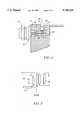
- FIG. 1is a side elevational view of a package microwave circuit employing an electrical impulse suppressor in accordance with the invention.
- FIG. 2is a sectional view taken generally along the line 2--2 of FIG. 1 showing an electrical impulse suppressor in accordance with the present invention interposed between a coaxial transmission line and a microstrip transmission line connected to a microwave circuit.
- FIG. 3is a sectional view taken along the line 3--3 of FIG. 2.
- FIG. 4is a sectional view taken along the line 4--4 of FIG. 3.
- FIG. 5is a schematic diagram of the electrical impulse suppressor of FIGS. 1-4.
- the coaxial transmission line which carries incoming microwave signalsis connected to a coaxial connector 11 such as a DIN connector secured to housing 12, FIG. 1.
- the housingincludes top and bottom plates 13, 14 secured to a frame 16.
- the microwave signalsare processed, such as amplified, down converted, etc. by a microwave circuit housed in the housing.
- the processed signalsare provided at output connector 17.
- the microwave processing circuitsare carried by a printed wiring board 18, FIGS. 2 and 3.
- the printed wiring boardis supported by a ledge 19 formed on the frame 16.
- an electrical impulse suppressoris interposed between the coaxial connector 11 and the microwave processing circuits (not shown) carried by the wiring board 14.
- the outer conductor of the coaxial connector 11is attached to and electrically connected to the frame 16 of the housing 12.
- the end wall 21 of the side wall ledges 19support the printed circuit wiring board 18 with the groundplane 22 of the board in electrical contact with the end wall 21.
- the end wall 21includes a well 23 which surrounds a center conductor 24 coaxiallysupported in the well by a dielectric sleeve 26.
- the center conductor 24issuitably connected to the center conductor of the connector 11 as for example by a socket 27.
- the conductive ground plane 22 of the laminate or printed wiring boardis secured to the block or end wall 21 as for example, by screws 28, which provide suitable pressure for good conductiveconnection.
- the printed wiring boardincludes a strip transmission line 31 which is connected to the center conductor 24 by a pin 32 and interacts with the ground plane to form a strip transmission line which is coupled to the associated microwave circuits (not shown) connected to the strip line section 33 by a bandpass filter which attenuates the flow of energy above and below a band limited range of frequencies.
- a discharge device 36 having known breakdown voltage, FIGS. 3 and 4, in thepresent example,comprises a gas discharge tube having conductive ends 37 and 38 connected between the center conductor 24 and the end wall 21.
- the gas discharge tubeis disposed in a threaded opening 39 formed in the end wall 21.
- the gas discharge tubeis placed in an opening and a screw 41 forces the conductive end 37 against a flat on the center conductor to form a competent electrical connection while the end 38 makes a competent electrical connection with the screw 41 which is received by the end wall 21 whereby the gas discharge tube is shunted at microwave frequencies between the center or primary transmission line and the outer or secondarytransmission line.
- the discharge tubeintroduces parasitic capacitance in the transmission line with a resulting impedance mismatch leading to high VSWR (voltage standing wave ratio).
- a bandpass filter networkcomprising quarter wavelength microstrip transmission lines, is employed to transfer energy from the center conductor to the output strip transmission line 33.
- the bandpass filteris implemented by a first shunt strip quarter wavelength transmission line 43.
- the quarter wavelength transmission line and the stray capacitance of the discharge tubeform a first resonant circuit.
- the shunt quarterwave transmission line 43is terminated by a quarterwave open circuited strip line 44 which introduces a microwave bypass to ground.
- DC control signalscan be introduced into the line via the DC bias port 45 and the quarterwave transmission line 43.
- Such an approachenables DC control signals to be introduced intothe transmission line with an element that also matches the parasitic capacitance of the gas tube such that the DC bias method fundamentally provides low insertion losses.
- Coupled strip transmission lines 46 and 47transfer energy along the transmission line. This allows the voltage to build up in the gas discharge tube until ionization occurs.
- the coupled transmission lines 46 and 47provide a series resonant circuit.
- Another quarter wave strip transmission line 48is in shunt with the transmission line 33.
- the actionof the shunt transmission line 48is to provide another resonant circuit.
- the action of the two shunt resonant circuits and the series resonant circuitis to form a bandpass filter structure that transfers a narrow band of frequencies along the line while blocking the transmission of signals outside the narrow band of operation.
- the networkalso provides animpedance match at the microwave frequencies while suppressing extraneous VHF/UHF signals.
- the quarter wavelength sectionsare accomplished with strip transmission lines whose characteristic impedances are determined bymodern filter synthesis techniques. It is understood from practical experience that the length of the strip transmission lines can vary considerably from the nominal quarterwave depending upon the various parasitics that are to be absorbed in the filter network. For example, thefirst transmission line shunted with the gas tube is shorter than the nominal quarter wavelength in order to absorb parasitic capacitance of thegas tube.
- FIG. 5shows the equivalent circuit with like reference numerals referring to like parts.
- the first transmission line 43 and gas tube capacitance 49form a first parallel resonant circuit.
- the coupled transmission lines 46 and 47form a second resonant circuit.
- the shunt transmission line 48forms a third resonant circuit.
- the three resonant circuitsform a bandpass filter which matches the characteristic impedance of the system and which transmits energy over a narrow band of frequencies while blocking signals above and below the narrow band of frequencies.
- the electromagnetic impulse suppressor of the present inventionis interposed between an electrical coaxial connector and a printed wiring board mounted microwave circuit with printed microstrip transmission lines.
- the gas tubeis mounted across the coaxial line in a manner commonly known in the industry.
- the coaxial lineis transitioned into the printed wiring board where all of the distributed elements are fabricated directly on the board.
- the suppressoris amenable to printed circuit boardwiring techniques which eliminate expensive hand labor and performance variability at microwave frequencies.
Landscapes
- Control Of Motors That Do Not Use Commutators (AREA)
Abstract
Description
Claims (3)
Priority Applications (5)
| Application Number | Priority Date | Filing Date | Title |
|---|---|---|---|
| US08/811,111US5745328A (en) | 1997-03-03 | 1997-03-03 | Electromagnetic impulse suppression curcuit |
| PCT/US1997/023572WO1998039830A1 (en) | 1997-03-03 | 1997-12-31 | Electromagnetic impulse suppression circuit |
| AU57112/98AAU5711298A (en) | 1997-03-03 | 1997-12-31 | Electromagnetic impulse suppression circuit |
| CA002281945ACA2281945A1 (en) | 1997-03-03 | 1997-12-31 | Electromagnetic impulse suppression circuit |
| EP97953345AEP0965158A1 (en) | 1997-03-03 | 1997-12-31 | Electromagnetic impulse suppression circuit |
Applications Claiming Priority (1)
| Application Number | Priority Date | Filing Date | Title |
|---|---|---|---|
| US08/811,111US5745328A (en) | 1997-03-03 | 1997-03-03 | Electromagnetic impulse suppression curcuit |
Publications (1)
| Publication Number | Publication Date |
|---|---|
| US5745328Atrue US5745328A (en) | 1998-04-28 |
Family
ID=25205593
Family Applications (1)
| Application Number | Title | Priority Date | Filing Date |
|---|---|---|---|
| US08/811,111Expired - Fee RelatedUS5745328A (en) | 1997-03-03 | 1997-03-03 | Electromagnetic impulse suppression curcuit |
Country Status (5)
| Country | Link |
|---|---|
| US (1) | US5745328A (en) |
| EP (1) | EP0965158A1 (en) |
| AU (1) | AU5711298A (en) |
| CA (1) | CA2281945A1 (en) |
| WO (1) | WO1998039830A1 (en) |
Cited By (6)
| Publication number | Priority date | Publication date | Assignee | Title |
|---|---|---|---|---|
| US20070053130A1 (en)* | 2005-09-01 | 2007-03-08 | Andrew Corporation | Offset Planar Coil Coaxial Surge Suppressor |
| US20070081287A1 (en)* | 2005-10-07 | 2007-04-12 | Andrew Corporation | Multiple Planar Inductor Coaxial Surge Suppressor |
| US20070097583A1 (en)* | 2005-10-31 | 2007-05-03 | Andrew Corporation | Tuned Coil Coaxial Surge Suppressor |
| US20070165352A1 (en)* | 2006-01-13 | 2007-07-19 | Andrew Corporation | Multiple Planar Inductive Loop Surge Suppressor |
| US20070268645A1 (en)* | 2006-05-22 | 2007-11-22 | Andrew Corporation | Tungsten Shorting Stub and Method of Manufacture |
| US20080170346A1 (en)* | 2007-01-17 | 2008-07-17 | Andrew Corporation | Folded Surface Capacitor In-line Assembly |
Citations (15)
| Publication number | Priority date | Publication date | Assignee | Title |
|---|---|---|---|---|
| US2030179A (en)* | 1933-01-19 | 1936-02-11 | American Telephone & Telegraph | Electrical circuit arrangement |
| US2777998A (en)* | 1952-09-11 | 1957-01-15 | Gen Electric | Electrical wave filter |
| US2886744A (en)* | 1956-03-21 | 1959-05-12 | Jr William E Mcnatt | Electrical protective apparatus |
| US2922913A (en)* | 1958-11-19 | 1960-01-26 | Lester A Cushman | Lightning arrester |
| US3274447A (en)* | 1963-03-14 | 1966-09-20 | Noel R Nelson | Coaxial cable lightning arrester |
| US3777219A (en)* | 1972-08-14 | 1973-12-04 | Gen Semiconductor Ind Inc | Electromagnetic pulse suppressor |
| US3863111A (en)* | 1973-06-29 | 1975-01-28 | Gen Electric | Polycrystalline varistor surge protective device for high frequency applications |
| US3968411A (en)* | 1975-03-27 | 1976-07-06 | The United States Of America As Represented By The Secretary Of The Army | Transmitter-receiver protection device |
| US4050092A (en)* | 1976-08-20 | 1977-09-20 | Tii Corporation | Multi-circuit protector |
| US4142220A (en)* | 1977-09-26 | 1979-02-27 | Reliable Electric Company | Multi arc gap surge arrester |
| US4158869A (en)* | 1977-08-19 | 1979-06-19 | Reliable Electric Company | Line protector |
| US4359764A (en)* | 1980-04-08 | 1982-11-16 | Block Roger R | Connector for electromagnetic impulse suppression |
| US4409637A (en)* | 1980-04-08 | 1983-10-11 | Block Roger R | Connector for electromagnetic impulse suppression |
| US4517497A (en)* | 1983-11-02 | 1985-05-14 | Reynolds Industries Inc. | Capacitor discharge apparatus |
| US4554608A (en)* | 1982-11-15 | 1985-11-19 | Block Roger R | Connector for electromagnetic impulse suppression |
Family Cites Families (2)
| Publication number | Priority date | Publication date | Assignee | Title |
|---|---|---|---|---|
| US4233579A (en)* | 1979-06-06 | 1980-11-11 | Bell Telephone Laboratories, Incorporated | Technique for suppressing spurious resonances in strip transmission line circuits |
| US4873501A (en)* | 1986-06-27 | 1989-10-10 | The United States Of America As Represented By The Secretary Of The Navy | Internal transmission line filter element |
- 1997
- 1997-03-03USUS08/811,111patent/US5745328A/ennot_activeExpired - Fee Related
- 1997-12-31EPEP97953345Apatent/EP0965158A1/ennot_activeWithdrawn
- 1997-12-31CACA002281945Apatent/CA2281945A1/ennot_activeAbandoned
- 1997-12-31WOPCT/US1997/023572patent/WO1998039830A1/ennot_activeApplication Discontinuation
- 1997-12-31AUAU57112/98Apatent/AU5711298A/ennot_activeAbandoned
Patent Citations (15)
| Publication number | Priority date | Publication date | Assignee | Title |
|---|---|---|---|---|
| US2030179A (en)* | 1933-01-19 | 1936-02-11 | American Telephone & Telegraph | Electrical circuit arrangement |
| US2777998A (en)* | 1952-09-11 | 1957-01-15 | Gen Electric | Electrical wave filter |
| US2886744A (en)* | 1956-03-21 | 1959-05-12 | Jr William E Mcnatt | Electrical protective apparatus |
| US2922913A (en)* | 1958-11-19 | 1960-01-26 | Lester A Cushman | Lightning arrester |
| US3274447A (en)* | 1963-03-14 | 1966-09-20 | Noel R Nelson | Coaxial cable lightning arrester |
| US3777219A (en)* | 1972-08-14 | 1973-12-04 | Gen Semiconductor Ind Inc | Electromagnetic pulse suppressor |
| US3863111A (en)* | 1973-06-29 | 1975-01-28 | Gen Electric | Polycrystalline varistor surge protective device for high frequency applications |
| US3968411A (en)* | 1975-03-27 | 1976-07-06 | The United States Of America As Represented By The Secretary Of The Army | Transmitter-receiver protection device |
| US4050092A (en)* | 1976-08-20 | 1977-09-20 | Tii Corporation | Multi-circuit protector |
| US4158869A (en)* | 1977-08-19 | 1979-06-19 | Reliable Electric Company | Line protector |
| US4142220A (en)* | 1977-09-26 | 1979-02-27 | Reliable Electric Company | Multi arc gap surge arrester |
| US4359764A (en)* | 1980-04-08 | 1982-11-16 | Block Roger R | Connector for electromagnetic impulse suppression |
| US4409637A (en)* | 1980-04-08 | 1983-10-11 | Block Roger R | Connector for electromagnetic impulse suppression |
| US4554608A (en)* | 1982-11-15 | 1985-11-19 | Block Roger R | Connector for electromagnetic impulse suppression |
| US4517497A (en)* | 1983-11-02 | 1985-05-14 | Reynolds Industries Inc. | Capacitor discharge apparatus |
Non-Patent Citations (6)
| Title |
|---|
| Aircraft Protection from Thunderstorm Discharges to Antennas, J.M. Bryant, M.M. Newman, J.D. Robb, AIEE, pp. 880 884, Oct. 1953.* |
| Aircraft Protection from Thunderstorm Discharges to Antennas, J.M. Bryant, M.M. Newman, J.D. Robb, AIEE, pp. 880-884, Oct. 1953. |
| Field Experience with Gas Filled Protectors on Communicator LInes, J.E.R. Lemieux IEEE, pp. 441 447, Jul. 1963.* |
| Field Experience with Gas-Filled Protectors on Communicator LInes, J.E.R. Lemieux IEEE, pp. 441-447, Jul. 1963. |
| Superfit Special Application Applicators, RMS Electronics, Inc., 1980.* |
| TII Condensed Catalog and Price List, TII Industries, Inc. Mar. 15, 1978.* |
Cited By (11)
| Publication number | Priority date | Publication date | Assignee | Title |
|---|---|---|---|---|
| US20070053130A1 (en)* | 2005-09-01 | 2007-03-08 | Andrew Corporation | Offset Planar Coil Coaxial Surge Suppressor |
| US7349191B2 (en) | 2005-09-01 | 2008-03-25 | Andrew Corporation | Offset planar coil coaxial surge suppressor |
| US20070081287A1 (en)* | 2005-10-07 | 2007-04-12 | Andrew Corporation | Multiple Planar Inductor Coaxial Surge Suppressor |
| US7324318B2 (en) | 2005-10-07 | 2008-01-29 | Andrew Corporation | Multiple planar inductor coaxial surge suppressor |
| US20070097583A1 (en)* | 2005-10-31 | 2007-05-03 | Andrew Corporation | Tuned Coil Coaxial Surge Suppressor |
| US20070165352A1 (en)* | 2006-01-13 | 2007-07-19 | Andrew Corporation | Multiple Planar Inductive Loop Surge Suppressor |
| US7483251B2 (en) | 2006-01-13 | 2009-01-27 | Andrew Llc | Multiple planar inductive loop surge suppressor |
| US20070268645A1 (en)* | 2006-05-22 | 2007-11-22 | Andrew Corporation | Tungsten Shorting Stub and Method of Manufacture |
| US7583489B2 (en) | 2006-05-22 | 2009-09-01 | Andrew Llc | Tungsten shorting stub and method of manufacture |
| US20080170346A1 (en)* | 2007-01-17 | 2008-07-17 | Andrew Corporation | Folded Surface Capacitor In-line Assembly |
| US8174132B2 (en) | 2007-01-17 | 2012-05-08 | Andrew Llc | Folded surface capacitor in-line assembly |
Also Published As
| Publication number | Publication date |
|---|---|
| CA2281945A1 (en) | 1998-09-11 |
| AU5711298A (en) | 1998-09-22 |
| EP0965158A1 (en) | 1999-12-22 |
| WO1998039830A1 (en) | 1998-09-11 |
Similar Documents
| Publication | Publication Date | Title |
|---|---|---|
| US5844766A (en) | Lightning supression system for tower mounted antenna systems | |
| US5432489A (en) | Filter with strip lines | |
| US5278720A (en) | Printed circuit-mounted surge suppressor matched to characteristic impedance of high frequency transmission line | |
| FI104661B (en) | Surface mounting filter with fixed transmission line connection | |
| US5710984A (en) | Radio transceiver with impedance matched test port | |
| US4740794A (en) | Connectorless antenna coupler | |
| WO2002103875A1 (en) | Protective device | |
| US3289117A (en) | Surge arrestor utilizing quarter wave stubs | |
| US4160210A (en) | Printed circuit impedance transformation network with an integral spark gap | |
| CN111786735B (en) | Ultra-wideband radio frequency coaxial strong electromagnetic pulse protection method and device | |
| GB656853A (en) | Antenna systems for radio receivers | |
| US5745328A (en) | Electromagnetic impulse suppression curcuit | |
| US6791813B2 (en) | Communication line surge protecting system | |
| US6104259A (en) | Harmonic suppression circuit | |
| EP0079688A2 (en) | Microwave diplexer | |
| AU661556B2 (en) | Filter | |
| US20050099754A1 (en) | Impedance matched surge protected coupling loop assembly | |
| KR200201406Y1 (en) | Lighting conductor apparatus of repeter and base for mobile communication | |
| CN111786734B (en) | Radio frequency coaxial strong electromagnetic pulse protection method and device | |
| US4112394A (en) | Method and means of link coupling with separate control of link reactance and coupling coefficient | |
| US2897499A (en) | Uhf antenna multicoupler system or the like | |
| US20250112351A1 (en) | Microwave band-pass filter with wide stopband using l-shaped slotted microstrip resonators | |
| US6831616B1 (en) | Transmission line balun with parasitic mode termination | |
| EP0258277A1 (en) | Dual band antenna permitting connectorless antenna coupler | |
| FI126789B (en) | Radio circuit switching circuit |
Legal Events
| Date | Code | Title | Description |
|---|---|---|---|
| AS | Assignment | Owner name:WATKINS-JOHNSON COMPANY, CALIFORNIA Free format text:ASSIGNMENT OF ASSIGNORS INTEREST;ASSIGNOR:BELLANTONI, JOHN V.;REEL/FRAME:008421/0462 Effective date:19970218 | |
| AS | Assignment | Owner name:FIRST UNION COMMERCIAL CORPORATION, VIRGINIA Free format text:SECURITY AGREEMENT;ASSIGNORS:TSMD ACQUISITION CORP.;STELLEX MICROWAVE SYSTEMS, INC.;REEL/FRAME:009556/0267 Effective date:19980529 | |
| AS | Assignment | Owner name:FIRST UNION COMMERICIAL CORPORATION, VIRGINIA Free format text:RELINQUISHMENT AND AMENDMENT TO AMENDED AND RESTATED PATENT SECURITY AGREEMENT;ASSIGNORS:TSMD ACQUISITION CORPORATION;STELLEX MICROWAVE SYSTEMS, INC.;REEL/FRAME:010310/0553;SIGNING DATES FROM 19990329 TO 19990330 | |
| AS | Assignment | Owner name:CANADIAN IMPERIAL BANK OF COMMERCE, NEW YORK Free format text:SECURITY INTEREST;ASSIGNOR:WATKINS-JOHNSON COMPANY;REEL/FRAME:010639/0115 Effective date:20000131 | |
| FEPP | Fee payment procedure | Free format text:PAYOR NUMBER ASSIGNED (ORIGINAL EVENT CODE: ASPN); ENTITY STATUS OF PATENT OWNER: SMALL ENTITY | |
| AS | Assignment | Owner name:WJ COMMUNICATIONS, INC., CALIFORNIA Free format text:MERGER;ASSIGNOR:WJ COMMUNICATIONS, INC.;REEL/FRAME:011590/0483 Effective date:20000811 | |
| AS | Assignment | Owner name:WJ COMMUNICATIONS, INC., CALIFORNIA Free format text:CHANGE OF NAME;ASSIGNOR:WATKINS-JOHNSON COMPANY;REEL/FRAME:011590/0401 Effective date:20000418 | |
| REMI | Maintenance fee reminder mailed | ||
| FEPP | Fee payment procedure | Free format text:PAT HOLDER CLAIMS SMALL ENTITY STATUS, ENTITY STATUS SET TO SMALL (ORIGINAL EVENT CODE: LTOS); ENTITY STATUS OF PATENT OWNER: SMALL ENTITY | |
| LAPS | Lapse for failure to pay maintenance fees | ||
| STCH | Information on status: patent discontinuation | Free format text:PATENT EXPIRED DUE TO NONPAYMENT OF MAINTENANCE FEES UNDER 37 CFR 1.362 | |
| FP | Lapsed due to failure to pay maintenance fee | Effective date:20020428 |