US5744921A - Control circuit for five-phase brushless DC motor - Google Patents
Control circuit for five-phase brushless DC motorDownload PDFInfo
- Publication number
- US5744921A US5744921AUS08/643,160US64316096AUS5744921AUS 5744921 AUS5744921 AUS 5744921AUS 64316096 AUS64316096 AUS 64316096AUS 5744921 AUS5744921 AUS 5744921A
- Authority
- US
- United States
- Prior art keywords
- windings
- rotor
- motor
- circuit
- control
- Prior art date
- Legal status (The legal status is an assumption and is not a legal conclusion. Google has not performed a legal analysis and makes no representation as to the accuracy of the status listed.)
- Expired - Fee Related
Links
- 238000004804windingMethods0.000claimsabstractdescription115
- 230000004044responseEffects0.000claimsabstractdescription19
- 230000003287optical effectEffects0.000claimsabstractdescription8
- 230000008859changeEffects0.000description8
- 238000010586diagramMethods0.000description8
- 230000001143conditioned effectEffects0.000description5
- 230000002441reversible effectEffects0.000description5
- 238000001816coolingMethods0.000description4
- 230000001133accelerationEffects0.000description3
- 239000003990capacitorSubstances0.000description3
- 238000004891communicationMethods0.000description3
- 230000003247decreasing effectEffects0.000description3
- 238000000034methodMethods0.000description3
- 230000002411adverseEffects0.000description2
- 230000009977dual effectEffects0.000description2
- 230000004907fluxEffects0.000description2
- 230000001939inductive effectEffects0.000description2
- 238000004806packaging method and processMethods0.000description2
- 230000001360synchronised effectEffects0.000description2
- 230000001052transient effectEffects0.000description2
- 238000004378air conditioningMethods0.000description1
- 239000011324beadSubstances0.000description1
- 230000015556catabolic processEffects0.000description1
- 230000003750conditioning effectEffects0.000description1
- 230000001276controlling effectEffects0.000description1
- 230000007423decreaseEffects0.000description1
- 230000001934delayEffects0.000description1
- 238000001514detection methodMethods0.000description1
- 230000006870functionEffects0.000description1
- 238000010438heat treatmentMethods0.000description1
- 238000004519manufacturing processMethods0.000description1
- 239000000463materialSubstances0.000description1
- 238000012986modificationMethods0.000description1
- 230000004048modificationEffects0.000description1
- 230000010355oscillationEffects0.000description1
- 238000013021overheatingMethods0.000description1
- 230000003071parasitic effectEffects0.000description1
- 230000008569processEffects0.000description1
- 230000009467reductionEffects0.000description1
- 230000001105regulatory effectEffects0.000description1
- 239000004065semiconductorSubstances0.000description1
- 238000009423ventilationMethods0.000description1
Images


Classifications
- H—ELECTRICITY
- H02—GENERATION; CONVERSION OR DISTRIBUTION OF ELECTRIC POWER
- H02P—CONTROL OR REGULATION OF ELECTRIC MOTORS, ELECTRIC GENERATORS OR DYNAMO-ELECTRIC CONVERTERS; CONTROLLING TRANSFORMERS, REACTORS OR CHOKE COILS
- H02P1/00—Arrangements for starting electric motors or dynamo-electric converters
- H02P1/16—Arrangements for starting electric motors or dynamo-electric converters for starting dynamo-electric motors or dynamo-electric converters
- H02P1/18—Arrangements for starting electric motors or dynamo-electric converters for starting dynamo-electric motors or dynamo-electric converters for starting an individual DC motor
- H02P1/22—Arrangements for starting electric motors or dynamo-electric converters for starting dynamo-electric motors or dynamo-electric converters for starting an individual DC motor in either direction of rotation
- H—ELECTRICITY
- H02—GENERATION; CONVERSION OR DISTRIBUTION OF ELECTRIC POWER
- H02P—CONTROL OR REGULATION OF ELECTRIC MOTORS, ELECTRIC GENERATORS OR DYNAMO-ELECTRIC CONVERTERS; CONTROLLING TRANSFORMERS, REACTORS OR CHOKE COILS
- H02P6/00—Arrangements for controlling synchronous motors or other dynamo-electric motors using electronic commutation dependent on the rotor position; Electronic commutators therefor
- H02P6/08—Arrangements for controlling the speed or torque of a single motor
- H—ELECTRICITY
- H02—GENERATION; CONVERSION OR DISTRIBUTION OF ELECTRIC POWER
- H02P—CONTROL OR REGULATION OF ELECTRIC MOTORS, ELECTRIC GENERATORS OR DYNAMO-ELECTRIC CONVERTERS; CONTROLLING TRANSFORMERS, REACTORS OR CHOKE COILS
- H02P6/00—Arrangements for controlling synchronous motors or other dynamo-electric motors using electronic commutation dependent on the rotor position; Electronic commutators therefor
- H02P6/14—Electronic commutators
- H02P6/16—Circuit arrangements for detecting position
- H02P6/17—Circuit arrangements for detecting position and for generating speed information
- H—ELECTRICITY
- H02—GENERATION; CONVERSION OR DISTRIBUTION OF ELECTRIC POWER
- H02P—CONTROL OR REGULATION OF ELECTRIC MOTORS, ELECTRIC GENERATORS OR DYNAMO-ELECTRIC CONVERTERS; CONTROLLING TRANSFORMERS, REACTORS OR CHOKE COILS
- H02P6/00—Arrangements for controlling synchronous motors or other dynamo-electric motors using electronic commutation dependent on the rotor position; Electronic commutators therefor
- H02P6/14—Electronic commutators
- H02P6/16—Circuit arrangements for detecting position
- H02P6/18—Circuit arrangements for detecting position without separate position detecting elements
- H02P6/182—Circuit arrangements for detecting position without separate position detecting elements using back-emf in windings
- H—ELECTRICITY
- H02—GENERATION; CONVERSION OR DISTRIBUTION OF ELECTRIC POWER
- H02P—CONTROL OR REGULATION OF ELECTRIC MOTORS, ELECTRIC GENERATORS OR DYNAMO-ELECTRIC CONVERTERS; CONTROLLING TRANSFORMERS, REACTORS OR CHOKE COILS
- H02P6/00—Arrangements for controlling synchronous motors or other dynamo-electric motors using electronic commutation dependent on the rotor position; Electronic commutators therefor
- H02P6/20—Arrangements for starting
- H02P6/22—Arrangements for starting in a selected direction of rotation
- H—ELECTRICITY
- H02—GENERATION; CONVERSION OR DISTRIBUTION OF ELECTRIC POWER
- H02P—CONTROL OR REGULATION OF ELECTRIC MOTORS, ELECTRIC GENERATORS OR DYNAMO-ELECTRIC CONVERTERS; CONTROLLING TRANSFORMERS, REACTORS OR CHOKE COILS
- H02P6/00—Arrangements for controlling synchronous motors or other dynamo-electric motors using electronic commutation dependent on the rotor position; Electronic commutators therefor
- H02P6/34—Modelling or simulation for control purposes
Definitions
- This applicationincludes a microfiche appendix including 1 microfiche and 35 frames.
- the inventiongenerally relates to a control system for a brushless direct-current (DC) motor.
- the inventionparticularly relates to a control system for a five-phase brushless DC motor including a stator having five windings adapted to be electronically commutated in response to the rotary position of a rotor mounted for rotation relative to the windings.
- Brushless DC motorsalso known as self-synchronous or electronically-commutated motors, are used in a variety of applications including land vehicle and aerospace applications.
- brushless DC motorsare used in automotive engine cooling applications and in heating, ventilation and air-conditioning (HVAC) equipment.
- HVACheating, ventilation and air-conditioning
- a brushless DC motormay include a stator wound with windings, or coils, and a rotor with rotor-mounted permanent magnets.
- An electronic control system or circuitswitches or commutates current in the proper stator windings at the correct time in a process known as commutation.
- the control systemresponds in real time to the sensed rotary position of the rotor to generate a coordinated sequence of control signals, which are provided to electronic switches such as transistors that control the flow of current through the windings.
- the current flow through each windingradiates a torque-inducing magnetic flux that causes the rotor to rotate.
- the sequential switching of current between the windingsproduces a magnetic flux oriented in a synchronized fashion that results in a torque on the rotor and causes rotational movement.
- the sequence of control signals generated in response to the sensed rotary position of the rotormaintains a desired relationship between the magnet positions on the rotor and the windings on the stator.
- each energized windinggenerates a sinusoidal relationship between phase angle and torque which is out of phase with the other windings.
- a control circuitenergizes three windings with a voltage displaced by a phase angle of 120 electrical degrees.
- three-phase motorsare used due to their capacity to provide a balanced power output, three-phase motors may be noisy and may not be suitable for high-temperature environments since all of the current flowing through the windings may flow through a single switch such as a transistor, thereby causing a high power dissipation per device.
- Various techniquescan be used to detect the rotary position of the rotor.
- Known systemsmay use sensors coupled to a motor shaft to detect the rotary angle of the motor shaft. These sensors may include Hall sensors, optical sensors and resolvers.
- sensorsmay include Hall sensors, optical sensors and resolvers.
- the use of discrete feedback sensors in the motormay adversely affect the size, cost, complexity, power consumption and, particularly with Hall sensors, reliability of the motor.
- some control circuitssense the back electromotive force (EMF) voltages generated in the windings as the motor rotates.
- EMFback electromotive force
- Back EMF magnitude and frequency informationcan be used to determine the rotary position of the rotor.
- the back EMF voltage signalsgenerally cannot be used for control during start-up or initial acceleration of the motor since the EMF signal is absent or undetectable when the rotor is stationary or rotating at low speed.
- a circuit for starting a sensorless brushless DC motoris shown in U.S. Pat. No. 4,678,973.
- the circuitstarts the motor by obtaining the direction of rotation upon start-up. If the rotor is rotating in a correct direction, the circuit energizes the windings to continue rotation. If the rotor is rotating in a wrong direction, the energization sequence is reversed to bring the rotor to a halt before starting is again attempted.
- the circuit as showncan not control start-up of a five-phase brushless DC motor.
- a control circuit for a five-phase brushless DC motorIt would be desirable to provide a control circuit for a five-phase brushless DC motor. It would also be desirable to provide a control system for starting a five-phase brushless DC motor by determining the direction of rotation of a rotor upon start-up and, if the rotor is rotating in a wrong direction, energizing at least two windings until the movement of the rotor comes substantially to a stop and then energizing the plurality of windings in a start-up sequence to cause the rotor to rotate in a correct direction. It would also be desirable to provide a multi-phase brushless DC motor wherein more than one winding is energized in parallel.
- the inventionrelates to a control system for electronically commutating a five-phase brushless DC motor adapted to be energized from a source of voltage.
- the motorincludes a stator having five windings adapted to be electronically commutated and a rotor mounted for rotation relative to the windings.
- the control systemincludes a sensing circuit configured to generate signals corresponding to the rotary position of the rotor, an electronic commutation circuit including switches coupled to the windings, and a control circuit coupled to the sensing circuit and the commutation circuit.
- the control circuitis configured to generate control signals in response to the rotary position of the rotor and to apply the control signals to the commutation circuit, wherein the commutation circuit controls the flow of current through the windings in response to the control signals.
- the inventionalso relates to a drive circuit for a five-phase brushless DC motor having five windings and a rotor mounted for rotation relative to the windings.
- the windingsare adapted to be energized by the timed application of drive voltages producing the flow of phase currents in the respective windings.
- the drive circuitincludes a plurality of position sensors configured to generate a pattern of signals related to the rotary position of the rotor, electrically controllable switches coupled to the windings, and a motor controller coupled to the position sensors and the controllable switches.
- the motor controlleris configured to generate commutation control signals based upon the pattern of signals received from the position sensors and to apply the control signals to the controllable switches, wherein the controllable switches control the flow of current through the windings in response to the control signals.
- the inventionrelates to a control system for a brushless DC motor adapted to be energized from a source of voltage.
- the motorincludes a stator having a plurality of windings adapted to be electronically commutated and a rotor mounted for rotation relative to the windings.
- the control systemincludes a sensing circuit configured to generate signals corresponding to the rotary position of the rotor, an electronic commutation circuit including switches coupled to the windings, and a control circuit coupled to the sensing circuit and the commutation circuit.
- the control circuitis configured to determine the direction of rotation of the rotor upon start-up and, if the rotor is rotating in a wrong direction, to energize at least two windings and wait for the movement of the rotor to come substantially to a stop.
- the control circuitis configured to then energize the plurality of windings in a start-up sequence to cause the rotor to rotate in a correct direction and, when the rotor is rotating in the correct direction, to electronically commutate the windings in response to the rotary position of the rotor.
- the inventionalso relates to a control system for electronically commutating a brushless DC motor adapted to be energized from a source of voltage.
- the motorincludes a stator having a plurality of windings adapted to be commutated and a rotor mounted for rotation relative to the windings.
- the control systemincludes a sensing circuit configured to generate signals corresponding to the rotary position of the rotor, an electronic commutation circuit including switches coupled to the windings, and a control circuit coupled to the sensing circuit and the commutation circuit.
- the control circuitis configured to generate pulse-width modulated control signals in response to the rotary position of the rotor and to apply the control signals to the commutation circuit, wherein the commutation circuit responds to the control signals by energizing at least two windings at generally the same time.
- FIG. 1is a block diagram of a five-phase unipolar DC brushless motor and a control system for electronically commutating the motor.
- FIG. 2is a block diagram showing the motor controller of FIG. 1.
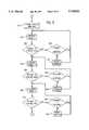
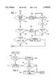
- FIGS. 3 through 7are exemplary flow chart diagrams showing the main procedure performed by the motor controller of FIG. 1.
- FIG. 8is an exemplary flow chart diagram showing the acceleration/deceleration timer interrupt routine executed by the motor controller of FIG. 1.
- FIG. 9is an exemplary flow chart diagram showing the compare timer interrupt routine executed by the motor controller of FIG. 1.
- FIG. 10is an exemplary flow chart diagram showing the stall handling routine executed by the motor controller of FIG. 1.
- FIG. 11is an exemplary flow chart diagram showing the afterrun routine executed by the motor controller of FIG. 1.
- FIGS. 12A through 12Eare a circuit schematic showing an exemplary implementation of the control system of FIG. 1.
- Control system 100for electronically commutating a brushless DC motor 102.
- Control system 100includes a motor power supply 104, a protection and rotor position sensing circuit 106, a controller power supply 108, a motor controller 110 and a power stage 112.
- Motor 102includes motor windings 114 and a motor rotor 116.
- Control system100 and motor 102can be packaged together or separately. Also, the components of control system 100 except for power stage 112 could be packaged separately from power stage 112, with motor 102 and power stage 112 packaged together.
- Motor power supply 104receives a DC voltage from a power source (not shown) via power leads 118 and 120.
- the power sourceis a battery supplying a 12 V signal.
- the power sourcecould be a DC voltage output from a power conditioning circuit which rectifies and filters an AC voltage source.
- a line filter 122 coupled to the power sourcelimits conducted RFI emissions.
- Line filter 122may include a passive LC filter network including inductors 124 and 126 connected in series with, and capacitors 128 and 130 connected in parallel across, power leads 118 and 120.
- balun or bead chokes for the inductorsmay simplify packaging due to a higher inductance/volume ratio than other known rod wound chokes.
- Motor power supply 104may include components to limit power supply current ripple including small value and electrolytic capacitors.
- a conditioned DC voltage output 132 from motor power supply 104supplies power to other control system 100 components and to motor 102.
- motor 102has a power range of 100 to 500 W.
- RFIradio frequency
- radiated RFImay be suppressed by shielding control system 100 and/or motor windings 114 in whole or in part using a shieldingmaterial.
- input/output leads from control system 100can be passed through noise suppressing grommets.
- film capacitors placed across the power terminals of the MOSFET driver chips used in powerstage 112 to amplify the control signals, as described below,may reduce conducted EMI emissions.
- Motor power supply 104includes a reverse voltage protection circuit 134 toprevent current flow through control system 100 during a reverse voltage condition (i.e., when the voltages at power leads 118 and 120 are reversed).
- Reverse voltage protection circuit 134includes a switch 136 and a diode 138.
- Switch 136is a MOSFET transistor which does not conduct current unless the gate voltage is positive. During a reverse voltage condition, the voltage at the MOSFET gate is negative and the MOSFET does not turn on, thereby preventing the flow of current through control system100 and protecting its components.
- Switch 136may include multiple MOSFETs in parallel. Alternatively, switch 136 may be a Schottky diode instead of a MOSFET. However, motor efficiency may be adversely affected since a Schottky diode has a larger forward voltage drop than a MOSFET.
- Motor power supply 104may include components to provide load dump protection.
- a varistorshown as RV1 in FIG. 12B protects control system 100 from transient voltage spikes.
- the varistormay be, forexample, a CU2220K30AUTOG automotive varistor.
- the varistor rating selectiondetermines the cutoff level of the voltage transient spike.
- Sensing circuit 106includes circuitry for sensing parameters and generating signals used by motor controller 110 to protect control system 100 and motor 102 as described below.
- the signalsare applied to motor controller 110 over lines 140.
- An over/under voltage circuitgenerates a signal based upon conditioned voltage output 132.
- An overcurrent circuitgenerates a signal based upon the current flowing through control system 100.
- an overtemperature circuitmay be used to generate a signal based upon a sensed temperature.
- the sensed signalispreferably an analog voltage scaled to a voltage within the range of an A/Dconverter within motor controller 110.
- each signalmay also be a logic signal (e.g., 0 or 5 V) indicating whether or not a fault condition has occurred.
- Motor controller 110may poll for fault conditions, or may be interrupted when a fault condition occurs.
- the over/under voltage circuitgenerates an analog 0 to 5 V signal from the conditioned voltage output 132 using a voltage divider.
- the overcurrent circuitgenerates an analog 0 to 5 V signal by sensing the voltage drop across a sense resistor shown in FIG. 12B as R56.
- the overcurrent circuitcould sense the voltage drop across RFI choke 126 which is generally proportional to current, and the temperature of choke 126 could be sensed and used to compensate the sensedvoltage in hardware or software.
- the overcurrent circuitcould sense the voltage drop across the MOSFET 136 or across a switch in power stage 112.
- the circuitwill preferably generate an analog 0 to 5 V signal using a zener diode, semiconductor temperature sensor, RTD or MOSFET 136. If MOSFET 136 is used, the RDS on of MOSFET 136 can be indirectly measured by measuring a voltage drop across it. In each case, motor controller 110 converts the sensed analog signal to a digital value and compares the digital value to a threshold limit or a range to determine whether a faultoccurred. If a fault occurs, motor controller 110 invokes a fault handling sequence as described below.
- Sensing circuit 106also includes circuitry for sensing the rotary positionof motor rotor 116 and generating signals corresponding to the rotary position.
- Motor controller 110uses the rotary position signals to controlthe start-up, commutation and speed of motor 102, and to protect against stall or reduced speed conditions. The signals are also applied to motor controller 110 over lines 140.
- motor 102has an operating speed range of 200 to 5000 rpm.
- sensing circuit 106may sense signals from optical or magnetic sensors coupled to a shaft of motor102 to sense the rotary angle of the shaft.
- Optical sensorsmay use a toothed wheel mechanically linked to the motor shaft, with the teeth synchronized with the back EMF in the motor windings 114 in a manner such that the breaking of an optical switch represents a positive or negative back EMF polarity, and the making of an optical switch represents a negative or positive back EMF polarity.
- Magnetic sensorsmay be used in the same manner as optical switches with a separate magnetic wheel, or by obtaining position information from the rotor magnets themselves.
- Sensing circuit 106may also use signals from resolvers or Hall sensors.
- Sensing circuit 106may also sense the back EMF voltages generated in motorwindings 114 as motor 102 rotates.
- the back EMF signalscan be compared to each other or to a voltage reference which may be fixed in magnitude, or may be variable depending on motor speed or load.
- Motor controller 110determines the position of motor rotor 116 based upon the back EMF signals. In one embodiment, the back EMF from five pairs of windings are compared to generate five discrete position signals.
- Controller power supply 108includes a voltage regulator which receives conditioned voltage output 132 from motor power supply 104 and provides a lower voltage source for sensing circuit 106 and motor controller 110.
- Theregulated voltageis typically 5 V, and is applied to sensing circuit 106 and to motor controller 110 via lines 142 and 144, respectively.
- motor controller 110receives signals based upon sensedparameters and the rotary position of motor rotor 116 from sensing circuit 106, and receives regulated power from controller power supply 108. Motor controller 110 also receives a speed setpoint signal 146. Speed setpoint signal 146 is used by motor controller 110 to set a desired, or reference,speed of motor 102. Speed setpoint signal 146 may be an analog voltage or current, or may be a digital signal from a serial or parallel communication interface. For example, speed setpoint signal 146 may be transmitted to motor controller 110 by a vehicle engine control unit (ECU), and may be part of a stream of communications data which controls the speed and duration of motor 102. In an HVAC application, speed setpoint signal 146 may be generated by an operator-controlled electronic circuit such as an analog potentiometer or a digital potentiometer with a keypad input device (not shown).
- ECUvehicle engine control unit
- speed setpoint signal 146may be generated by an operator-controlled electronic circuit such as an analog potentiometer or a digital pot
- Motor controller 110generates control signals for motor windings 114 whichare applied to power stage 112 via line 148.
- Power stage 112amplifies the logic-level control signals and uses the amplified signals to turn on electronic switches coupled to motor windings 114.
- the electronic switchesare MOSFET power transistors connected in series with motor windings 114, with one switch coupled to the bottom 150 of each motor phase.
- the top 152 of each motor phaseis connected to conditioned voltage output 132.
- Motor controller 110provides a pulse-width modulated (PWM) control signal above the audible range (e.g., between 20 and 40 KHz).
- the duty cycle of the PWM signalmay be varied between 0 and 100%, representing a speed of motor 102 between 0 and a maximum speed.
- the PWM signalis multiplexed to control different switches based upon the rotary position of motor rotor 116.
- Motor controller 110is also capable of converting speed setpoint signal 146 to a block of variable duration which may be used to commutate motor windings 114 (i.e., block commutation).
- motor controller 110controls the start-up, commutation and speed of motor 102 by varying the duty cycle and multiplexing of the control signals to power stage 112.
- motor controller 110may use linear control to drive current through windings 114.
- the use of PWM control signalsminimizes or at least reduces power dissipation in the windings and is more suitable for high-temperature applications.
- Motor controller 110alsoprovides protection for motor windings 114 and the switches within power stage 112 by modifying the control signals based upon sensed parameters and rotor position as described below.
- Motor 102includes motor windings 114 and motor rotor 116.
- a five-phase brushless DC motorincludes a stator wound with five windings 114.
- Motor rotor 116is mounted in a manner allowing for rotation relative to windings 114.
- Motor 102 shown in FIG. 1is a unipolar motor which includespermanent magnets creating one north pole 156 and one south pole 158. However, motor 102 could also include more than one pole.
- motor controller 110may be an analog, digital or combination analog and digital circuit.
- motor controller 110includes a microprocessor or microcontroller 200 coupled toa clock 202, a non-volatile memory 204 such as a read-only memory (ROM) forstoring program instructions executed by microprocessor 200, a volatile memory 206 such as a random-access memory (RAM), an analog-to-digital (A/D) converter 208 and a digital input/output interface 210.
- Microprocessor 200may be an 80517 microcontroller with built-in memory.
- non-volatile memory 204may be an EPROM, EEPROM or FLASH memory external to microprocessor 200 and volatile memory 206 could be an external RAM device.
- Non-volatile memory 204allows a user to tailor or customize the performance, fault handling and communication interfaces of motor 102 in software.
- Non-volatile memory 204may also include a separate FLASH or EEPROM memory programmed during the production of motor 102 with data taking into account motor-to-motor variations and special customer requirements.
- A/D converter 208receives analog voltage signals from the over/under voltage circuit, overcurrent circuit, overtemperature circuit (if used) and the speed setpoint interface (if analog) as described above.
- Digital input/output interface 210receives position signals of motor rotor 116 from sensing circuit 106 and transmits control signals to the MOSFET drivers of power stage 112.
- Motor controller 110can also include an analog or digital interface, such as an RS-232 serial interface, to communicate with an external device, such as an ECU. Using the interface, motor controller 110 can receive control parameters (e.g., speed setpoint signal 146) from the external device and transmit operating parameters and performance data (e.g., speedor temperature) as well as diagnostic data (e.g., faults) to the external device.
- control parameterse.g., speed setpoint signal 146
- performance datae.g., speedor temperature
- diagnostic datae.g., faults
- motor controller 110includes a PWM interface which receives a PWM signal from an ECU. During normal operation, the ECU transmits a 300 Hz PWM signal to motor controller 110 with a duty cycle representative of speed setpoint signal 146. The ECU can also command motor controller 110 to switch to an afterrun mode of operation by switching the PWM signal to a 10 Hz signal with the vehicle stopped. In afterrun operation, motor controller 110 runs motor 102 for a period of time to cool the engine compartment after the vehicle stops, thereby preventing excessive heat build-up. The duty cycle of the PWM signal sets the duration and speed of motor 102.
- control system 100includes a sensing circuit106 which senses the back EMF voltages generated in motor windings 114 to determine the rotary position of rotor 116, and that motor controller 110 receives a PWM command signal from an external device such as an ECU.
- the flowchartmay be changed as appropriate for other embodiments of the invention.
- motor controller 110performs initialization logic when power is applied to control system 100, such as when vehicle ignitionis turned on.
- motor controller 110checks speed setpoint signal 146 and inhibits start-up of motor 102 if the setpoint is not within a predetermined range.
- a PWM signal providing the speed setpoint signalhas a duty cycle range of between 10% and 90%.
- the systemchecks battery voltage by digitizing the analog voltage signal sensed by the over/under voltage circuit. An over-voltage condition is detected when sensed voltage exceeds an upper limit and an under-voltage condition is detected when sensed voltage is less than a lower limit.
- Range limitscan be user-specified in software, and are set at approximately 9 and 16 V in a preferred embodiment. The limits are compatible with typical battery voltage of 12 V and an operating range between 8 and 19 V. Start-up is inhibited if the voltage level is unacceptable.
- motor controller 110checks the direction of rotation of rotor116 by examining the rotor position signals from sensing circuit 106. If rotor 116 is stationary or moving in a wrong direction when power is applied, the system brakes motor 102 and moves rotor 116 into a fixed position as shown in steps 314 to 330. In a preferred embodiment, motor controller 110 energizes one winding (e.g., phase A) of motor 102 for a period of time and then energizes two windings (e.g., phases A and B) until rotor 116 comes to rest in the fixed position. Current applied to the windings is adjusted to a setpoint value during the braking sequence at steps 324 through 330. After movement stops, or after phases A and B have been energized for a time period, motor controller 110 executes a start-up sequence at step 332.
- one windinge.g., phase A
- two windingse.g., phases A and B
- motor controller110sequences windings 114 in an open-loop start-up sequence to cause rotor116 to rotate in the correct direction and attain a speed sufficient to generate detectable back EMF signals.
- the start-up sequenceenergizes windings 114 in four steps.
- phase Eis energizeduntil a falling edge signal is detected by sensor E (FIGS. 12A through 12E show how windings 114 and sensors 106 are labeled).
- phase Dis energized until a falling edge signal is detected by sensor D.
- phase Cis energized until a falling edge signal is detected by sensor C.
- phases C and Dare energized for a time period.
- rotor 116should be rotating in the correct direction at a speed sufficient for sensing circuit 106 to detect back EMF signals suitable for closed-loop control.
- current applied to motor windings 114is limited in the first three steps of the start-up sequence to a setpointvalue to prevent damage to windings 114 and/or power stage 112.
- motor controller 110commutates motor windings 114 based on therotary position of the rotor.
- Motor controller 110generates the PWM control signals to commutate motor windings 114 based upon a binary pattern received from the position sensors.
- the commutation algorithmplease refer to the software listing in the microfiche appendix.
- two motor windings 114are commutated at a time, with both motor windings turned on and off generally together.
- Energizing multiple windings using multiple switchesdecreases the flow of current through each switch by providingparallel paths for the total current flow. For example, if two phases are energized, two switches controlling the flow of current through the windings each carries one-half of the total current. Each switch dissipates less power and runs cooler than a system in which only one winding is energized at a time since each switch carries only a fraction of the total current.
- the reduction in current through each switch, as well as the use of PWM driversminimizes or at least reduces the power dissipation of windings 114 and allows motor 102 to operate more reliably in high-temperature environments.
- the inductive energy stored in the windingsis released when the current tothe windings is turned off.
- the energy release during coil turn offcan be decreased by using alternate chopping. Alternate chopping distributes the release of energy from the two windings over time and results in a smaller magnitude of energy release, thereby reducing conducted and radiated noise emissions.
- Active snubbingrather than passive snubbing, may be used to conduct energy stored in the windings during the off portion back to the positive rail quickly and efficiently.
- the use of active snubbingsuppresses parasitic oscillations and ringing during turn off, and minimizes the voltage across the conducting MOSFET drains, preventing avalanche breakdown of the device. If the energy stored in the MOSFET's is released to the positive rail quickly, the energy stored in the coils will not heatthe snubber circuit, and the temperature rise inside the motor will be decreased.
- planar snubber circuitmay be used rather than a snubber using discrete components.
- the planar snubberhas its resistance and capacitance distributed across the length and width of the circuit, which results in a smaller packaging size, and which is believed to provide lower power dissipation and lower radiated RFI.
- motor controller 110determines whether the frequency of the PWM input signal indicates that afterrun mode is commanded. A 300 Hz frequency indicates normal mode and a 10 Hz frequency indicates afterrun mode. If afterrun mode is commanded, a bit is set at step 368 and motor controller 110 jumps to the afterrun logic (described below in relation toFIG. 11) at step 370.
- motor controller 110detects whether a change occurred in speed setpoint signal 146. If so, the system sets an accel/decel timer andwaits for an interrupt at step 374. If not, the system calculates a speed and commutation delay at step 376.
- motor controller 110monitors the battery voltage and speed setpoint signal 146. If battery voltage is not within range, or if speed setpoint signal 146 is below a minimum value (e.g., a duty cycle of less than 10%), then motor 102 is disabled by cutting off the control signals to power stage 112. Motor 102 remains disabled and continues to idle until the voltage or speed setpointfault disappears, at which point the system re-starts.
- a minimum valuee.g., a duty cycle of less than 10%
- the systemdetects the current flowing through control system 100 by converting the analog voltage signal generated by the overcurrent circuit as described above. If the current exceeds a threshold limit (e.g., 33 Amps) specified by the user in software, the current applied to motor 102 is limited by decreasing the duty cycle of the PWM control signals at step 392. The current may also be limited based upon a feedbackfrom the over/under voltage circuit. Thus, variations in battery voltage and load are taken into account. For example, the current flowing through motor windings 114 can be limited at higher voltages to ensure that a defrost function is available in the event of a voltage regulator failure.The logic then repeats at step 364.
- a threshold limite.g. 33 Amps
- Motor controller 110may also be configured to check for an overtemperaturecondition by converting an analog voltage signal generated by an overtemperature circuit.
- An overtemperature conditionwould exist when thesensed temperature exceeds a user-defined threshold temperature. Different threshold temperatures may be specified for different power levels.
- the systemmay limit the pulse width of the control signals such that motor 102 operates at a lower speed. For example, if high ambient temperature results in an overtemperature condition, and motor 102 is rotating an engine cooling fan, motor 102 would not be completely de-energized so as to continue to provide a cooling air flow and prevent overheating of the engine. Desired full motor speed and power would not be restored unless the temperature falls below the threshold.
- motor controller 110executes an accel/decel timer interrupt routine to change the speed of motor 102 if the accel/decel timer was set at step 374 in response to a change in speed setpoint signal146 and the change has not yet been achieved.
- Steps 400 through 406change the PWM duty cycle at a predetermined rate until the desired duty cycle isachieved.
- the rates of change of the duty cyclegoverns the acceleration and deceleration rates of motor 102 and are set in software.
- the systemmay set the speed of motor 102 by comparing the actual speed of rotor 116, determined by measuring the time between successive rotary positions of rotor 116, with a desired speed from setpoint signal 146.
- Theduty cycle of the control signalis varied to provide closed-loop speed control.
- Various control algorithmsmay be used to control speed in a closed-loop fashion, such as proportional-integral-derivative (PID) or fuzzy logic. Closed-loop speed control can guarantee motor performance under various conditions such as varying battery voltage.
- motor controller 110executes a compare timer interrupt routine at step 410.
- the new rotor positionis read.
- a commutation delayis started if the new state is not equal to the old state.
- motor controller 110loads the new rotor position once the commutation delay is over.
- the compare channel registersare loaded with duty cycle information.
- the speedis read if a certain position has been reached (e.g., position 5) and the speed has notalready been read once. Further details are available in the program listing.
- motor controller 110starts a timer or integrator each time a different rotor position is detected.
- a stall/reduced speed faultis detected if the rotor position stays the samefor a time greater than the time required to change position at the lowest possible operating speed (e.g., 32 rpm) under normal operating conditions.
- motor controller 110may start a timer or integrator once per revolution of rotor 116. If rotor 116 reaches the same position withina specified time, the timer or integrator is reset. However, if the timer times out or the integrator output signal reaches a threshold level, a fault is detected.
- Motor controller 110may also detect a stall/reduced speed condition by determining the speed of rotor 116 based upon a time derivative of rotor position, and comparing the speed to a user-specified stall/reduced speed value.
- the systemmay detect astall based upon an excessive level of sensed current.
- current sensingmay be undesirable since excessive stall currents may not occur ifmotor 102 stalls at very low speeds.
- step 434power to motor 102 is cut if a stall or reduced speed condition is detected in order to protect motor 102 and power stage 112 when rotation of rotor 116 is obstructed.
- motor controller 110attempts to restart motor 102 after a stall is detected. The system waits a predetermined amount of time between restarting attempts depending on the number of stalls detected. As shown at steps 444 through 448, once a predetermined number of stalls has been detected, the system sets a diagnostic error bit, delays for a time period, clears the stall counter and restarts motor 102. Alternatively, upon detecting a stall condition, motor controller 110 may disable motor 102 and wait for power to be cycled (e.g., by turning the ignition off andthen on again) to re-start the system.
- motor controller 110executes an afterrun mode upon receiving an afterrun command.
- motor controller 110determines the duty cycle of the PWM command input. If the duty cycle is 15%, the system sets the desired PWM duty cycle (limited to a 35% maximum)of the control signals for motor 102 at step 454, starts an accel/decel timer at step 456, and operates motor 102 at the desired speed until the afterrun time is over or normal speed operation is desired as shown at steps 458 and 460. Steps 452 through 460 are repeated for various duty cycle values.
- a circuit schematicshows an exemplary implementation of control system 100 used to control a five-phase brushless DC motor.
- the integrated circuitsinclude a TLE4262G voltage regulator (U1), MC4423 MOSFET drivers (U2-U4), an LM2904 amplifier (U5), an 80517 microcontroller (U6) including internal memory, LM2901 comparators (U9 and U10), 74HC193 counters (U11-U14), and an MC3456 dual timer (U15). Labels U7 and U8 are unused.
- the reverse voltage protection and phase driver MOSFETsare BUZ342s (Q1-Q7). The components are connectedas shown in FIGS. 12A through 12E.
- tasks performed by various components of the schematic shownin FIGS. 12A through 12Emay be performed by a single integrated circuit.
- the tasks of microprocessor U6, counters U11 to U14 and dual timer U15may be combined in one integrated circuit, thereby increasing reliability and reducing cost.
Landscapes
- Engineering & Computer Science (AREA)
- Power Engineering (AREA)
- Control Of Motors That Do Not Use Commutators (AREA)
Abstract
Description
Claims (20)
Priority Applications (8)
| Application Number | Priority Date | Filing Date | Title |
|---|---|---|---|
| US08/643,160US5744921A (en) | 1996-05-02 | 1996-05-02 | Control circuit for five-phase brushless DC motor |
| EP97919226AEP0896760B1 (en) | 1996-05-02 | 1997-05-02 | Control circuit for five-phase brushless dc motor |
| DE69727477TDE69727477T2 (en) | 1996-05-02 | 1997-05-02 | Control circuit for a five-phase brushless current motor |
| JP9539368AJP2000509598A (en) | 1996-05-02 | 1997-05-02 | Control circuit for 5-phase brushless DC motor |
| KR1019980708815AKR100320259B1 (en) | 1996-05-02 | 1997-05-02 | Control circuit for five-phase brushless dc motor |
| CN97195715ACN1075282C (en) | 1996-05-02 | 1997-05-02 | Control circuit for five-phase brushless DC motor |
| PCT/CA1997/000298WO1997042701A1 (en) | 1996-05-02 | 1997-05-02 | Control circuit for five-phase brushless dc motor |
| TW086106645ATW338855B (en) | 1996-05-02 | 1997-05-19 | Control circuit for five-phase brushless DC motors |
Applications Claiming Priority (1)
| Application Number | Priority Date | Filing Date | Title |
|---|---|---|---|
| US08/643,160US5744921A (en) | 1996-05-02 | 1996-05-02 | Control circuit for five-phase brushless DC motor |
Publications (1)
| Publication Number | Publication Date |
|---|---|
| US5744921Atrue US5744921A (en) | 1998-04-28 |
Family
ID=24579614
Family Applications (1)
| Application Number | Title | Priority Date | Filing Date |
|---|---|---|---|
| US08/643,160Expired - Fee RelatedUS5744921A (en) | 1996-05-02 | 1996-05-02 | Control circuit for five-phase brushless DC motor |
Country Status (8)
| Country | Link |
|---|---|
| US (1) | US5744921A (en) |
| EP (1) | EP0896760B1 (en) |
| JP (1) | JP2000509598A (en) |
| KR (1) | KR100320259B1 (en) |
| CN (1) | CN1075282C (en) |
| DE (1) | DE69727477T2 (en) |
| TW (1) | TW338855B (en) |
| WO (1) | WO1997042701A1 (en) |
Cited By (118)
| Publication number | Priority date | Publication date | Assignee | Title |
|---|---|---|---|---|
| US5923145A (en)* | 1997-08-15 | 1999-07-13 | S-B Power Tool Company | Controller for variable speed motor |
| US6040668A (en)* | 1996-11-14 | 2000-03-21 | Telcom Semiconductor, Inc. | Monolithic fan controller |
| DE19921849A1 (en)* | 1999-05-11 | 2000-11-23 | Bosch Gmbh Robert | Electronically commutated motor |
| US6160367A (en)* | 1998-07-07 | 2000-12-12 | Matsushita Electric Industrial Co., Ltd. | Apparatus and method for driving motor |
| US6181093B1 (en)* | 1998-08-21 | 2001-01-30 | Fairchail Korea Semiconductor Ltd. | Commutation circuit for a sensorless three-phase brushless direct curent motor |
| US6326750B1 (en)* | 1999-06-17 | 2001-12-04 | Emerson Electric Co. | Active reduction of torque irregularities in rotating machines |
| WO2001076057A3 (en)* | 2000-03-31 | 2002-04-04 | Ljm Products Inc D B A Jmc Pro | Cooling module incorporating communication port and related circuits |
| US6369532B2 (en) | 2000-02-24 | 2002-04-09 | Briggs & Stratton Corporation | Control system for an electric motor having an integral flywheel rotor |
| US6392372B1 (en) | 2000-03-31 | 2002-05-21 | Ljm Products, Inc. | Brushless DC fan module incorporating integral fan control circuit with a communication port for receiving digital commands to control fan |
| US6400116B1 (en)* | 1998-06-09 | 2002-06-04 | Nsk Ltd. | Motor drive control apparatus |
| US6424798B1 (en)* | 1999-05-31 | 2002-07-23 | Denso Corporation | Device for controlling sensorless brushless-DC-motor |
| US20020141122A1 (en)* | 2001-04-03 | 2002-10-03 | Mitsubishi Denki Kabushiki Kaisha | Apparatus and method for protecting starter for engine against overheating |
| US6462495B1 (en) | 2000-04-25 | 2002-10-08 | Infineon Technologies Ag | Controlling a brushless DC motor |
| US6473562B1 (en)* | 1999-09-06 | 2002-10-29 | Wilo Gmbh | Method for low-speed operation of brushless DC motors |
| US6486633B1 (en)* | 1998-12-23 | 2002-11-26 | Mannesmann Vdo Ag | Method for monitoring the speed of a synchronous motor, and a device for monitoring the speed of such a motor |
| US20020183902A1 (en)* | 1998-09-25 | 2002-12-05 | Gotthilf Koerner | Method and system for controlling and/or regulating operating sequences in a motor vehicle in a brake system |
| US6512341B2 (en)* | 2000-07-14 | 2003-01-28 | Matsushita Electric Industrial Co., Ltd. | Apparatus and method for driving a brushless motor |
| US20030057899A1 (en)* | 2001-12-13 | 2003-03-27 | Lacroix Michael Charles | Linear electric motor controller and system for providing linear control |
| US20030063900A1 (en)* | 2001-12-13 | 2003-04-03 | Carter Group, Inc. | Linear electric motor controller and system for providing linear speed control |
| US20030080709A1 (en)* | 1998-08-14 | 2003-05-01 | Jorg Hornberger | Arrangement with an electric motor |
| US20030107353A1 (en)* | 2001-12-11 | 2003-06-12 | Honda Giken Kogyo Kabushiki Kaisha | Method of starting an electric brushless rotating machine for driving an internal combustion engine |
| US20030117100A1 (en)* | 2001-12-21 | 2003-06-26 | Pigott John M. | Method and apparatus for detecting a stall condition in a stepping motor |
| US6593716B1 (en) | 2000-11-21 | 2003-07-15 | Honeywell International Inc. | Circuit using current limiting to reduce power consumption of actuator with DC brush motor |
| US20030173916A1 (en)* | 2000-05-03 | 2003-09-18 | Horton Inc. | Brushless DC ring motor cooling system |
| US6674621B2 (en)* | 2000-11-21 | 2004-01-06 | Texas Instruments Incorporated | IC PMOS Schottky reverse bias protection structure |
| US6696804B1 (en) | 1999-09-15 | 2004-02-24 | Robert Bosch Gmbh | Electronically commutatable motor comprising an electronic control unit |
| US20040056153A1 (en)* | 2001-11-13 | 2004-03-25 | Smiths Aerospace, Inc. | Flight lock actuator with dual energy sources |
| US20040061467A1 (en)* | 2002-10-01 | 2004-04-01 | Ke Liu | Speed-based open-loop start-up method for brushless DC motor |
| US20040095089A1 (en)* | 2002-11-19 | 2004-05-20 | Collier-Hallman Steven James | Transient compensation voltage estimation for feedforward sinusoidal brushless motor control |
| US20040183489A1 (en)* | 2003-03-20 | 2004-09-23 | Siemens Vdo Automotive Inc. | Coupled RFI choke as stall detection means for brush type DC motor |
| US20040207966A1 (en)* | 2003-04-21 | 2004-10-21 | Lien-Ken Lin | Fan protection method and apparatus |
| US6825625B1 (en)* | 1998-06-13 | 2004-11-30 | Ebm-Papst St. Georgen Gmbh & Co. Kg | Device with an electromotor |
| US6838839B2 (en)* | 2000-10-25 | 2005-01-04 | Matsushita Electric Industrial Co., Ltd. | Electric circuit of electric vehicle |
| US20050046374A1 (en)* | 2003-02-12 | 2005-03-03 | International Business Machines Corporation | Information processor and rotation control device therefor |
| US6901212B2 (en)* | 2002-06-13 | 2005-05-31 | Halliburton Energy Services, Inc. | Digital adaptive sensorless commutational drive controller for a brushless DC motor |
| US20050135794A1 (en)* | 2003-12-22 | 2005-06-23 | General Electric Company | Method and system for negative torque reduction in a brushless DC motor |
| US20050188989A1 (en)* | 2002-03-08 | 2005-09-01 | Alain Delache | Air assistance apparatus providing fast rise and fall of pressure within one patient's breath |
| US20050243482A1 (en)* | 2004-04-30 | 2005-11-03 | Datech Technology Co., Ltd. | Brushless DC fan motor driving circuit |
| US20050264253A1 (en)* | 2003-10-21 | 2005-12-01 | Mladen Ivankovic | Linear power module |
| US20060038529A1 (en)* | 2004-08-21 | 2006-02-23 | Park Hyeong-Wook | Rotation units and control systems having rotational direction control and methods of controlling the same |
| US20060067019A1 (en)* | 2003-11-10 | 2006-03-30 | Meng-Chic Lin | Protective circuit for a motor |
| WO2005055694A3 (en)* | 2003-12-08 | 2006-06-22 | Sta Rite Industries | Pump control system and method |
| WO2006075795A1 (en)* | 2005-01-17 | 2006-07-20 | Toyota Jidosha Kabushiki Kaisha | Drive system and control method of the same |
| US20070001635A1 (en)* | 2005-07-01 | 2007-01-04 | International Rectifier Corporation | Method and system for starting a sensorless motor |
| US7170242B1 (en) | 2005-11-16 | 2007-01-30 | Sunonwealth Electric Machine Industry Co., Ltd. | Pulse-width-modulation motor drive circuit |
| SG129220A1 (en)* | 2002-04-03 | 2007-02-26 | Adda Corp | DC brushless motor having a control circuit |
| WO2007037977A3 (en)* | 2005-09-23 | 2007-06-28 | Gm Global Tech Operations Inc | Multiple inverter system with single controller and related operating method |
| US20070236846A1 (en)* | 2003-06-26 | 2007-10-11 | Delta Electronics, Inc. | Fan protection method and fan system |
| US20080023256A1 (en)* | 2006-07-28 | 2008-01-31 | Krieger Geoff P | Quadrant dependent active damping for electric power steering |
| US20080024028A1 (en)* | 2006-07-27 | 2008-01-31 | Islam Mohammad S | Permanent magnet electric motor |
| US20080023255A1 (en)* | 2006-07-28 | 2008-01-31 | Colosky Mark P | Compensation of periodic sensor errors in electric power steering systems |
| US20080147276A1 (en)* | 2006-12-15 | 2008-06-19 | Delphi Technologies, Inc. | Method, system, and apparatus for providing enhanced steering pull compensation |
| US20080303461A1 (en)* | 2004-06-22 | 2008-12-11 | Norbert Knab | Method and Apparatus for Detecting Blocking of a Direct Current Motor |
| US20090091279A1 (en)* | 2006-05-04 | 2009-04-09 | Andras Lelkes | Control unit for an electric motor, in particular for a fan motor |
| US20090140676A1 (en)* | 2007-11-29 | 2009-06-04 | Gm Global Technology Operations, Inc. | Method and system for sensorless control of an electric motor |
| WO2009007681A3 (en)* | 2007-07-07 | 2009-06-18 | Trw Ltd | Electric motor control |
| US20090184678A1 (en)* | 2008-01-22 | 2009-07-23 | Gm Global Technology Operations, Inc. | Permanent magnet ac motor systems and control algorithm restart methods |
| US20100123421A1 (en)* | 2008-11-18 | 2010-05-20 | Honeywell International Inc. | Hvac actuator with output torque compensation |
| US20100259137A1 (en)* | 2007-12-14 | 2010-10-14 | Alfred Goerlach | Generator including a rectifier system |
| US20100310382A1 (en)* | 2009-06-09 | 2010-12-09 | Melissa Drechsel Kidd | Method of Controlling a Pump and Motor |
| WO2010105795A3 (en)* | 2009-03-16 | 2011-03-10 | Brose Fahrzeugteile Gmbh & Co. Kommanditgesellschaft Hallstadt | Correction of counting errors upon evaluation of current ripples in a dc motor |
| US20110095713A1 (en)* | 2009-10-27 | 2011-04-28 | Gm Global Technology Operations, Inc. | Method and system for initiating operation of an electric motor |
| US20120185844A1 (en)* | 2010-07-16 | 2012-07-19 | Siemens Aktiengesellschaft | Method for starting up machines or machines in a machine series and planning system |
| US20120319626A1 (en)* | 2011-06-16 | 2012-12-20 | Rene Wichert | Battery operated electric motor in a work apparatus |
| US20130093374A1 (en)* | 2011-10-14 | 2013-04-18 | Dyson Technology Limited | Method of starting a brushless motor |
| US8465262B2 (en) | 2004-08-26 | 2013-06-18 | Pentair Water Pool And Spa, Inc. | Speed control |
| WO2013025753A3 (en)* | 2011-08-17 | 2013-07-04 | Trane International Inc. | Reverse rotation braking for a pm motor |
| US8500413B2 (en) | 2004-08-26 | 2013-08-06 | Pentair Water Pool And Spa, Inc. | Pumping system with power optimization |
| US8564233B2 (en) | 2009-06-09 | 2013-10-22 | Sta-Rite Industries, Llc | Safety system and method for pump and motor |
| US8573952B2 (en) | 2004-08-26 | 2013-11-05 | Pentair Water Pool And Spa, Inc. | Priming protection |
| US8602745B2 (en) | 2004-08-26 | 2013-12-10 | Pentair Water Pool And Spa, Inc. | Anti-entrapment and anti-dead head function |
| EP2696461A3 (en)* | 2012-08-10 | 2014-03-26 | Eaton Corporation | Electromechanical apparatus and electrical switching apparatus employing electronic circuit to condition motor input power |
| US8786244B2 (en) | 2011-09-22 | 2014-07-22 | GM Global Technology Operations LLC | System and method for current estimation for operation of electric motors |
| US8801389B2 (en) | 2004-08-26 | 2014-08-12 | Pentair Water Pool And Spa, Inc. | Flow control |
| US20150002059A1 (en)* | 2013-06-29 | 2015-01-01 | Rockwell Automation Technologies, Inc. | Method and apparatus for stability control of open loop motor drive operation |
| US20150008855A1 (en)* | 2013-07-02 | 2015-01-08 | Dyson Technology Limited | Controller for a brushless motor |
| US20150028781A1 (en)* | 2012-01-24 | 2015-01-29 | Magna Electronics Inc. | Method for actuating a bldc motor |
| US20150108922A1 (en)* | 2013-10-22 | 2015-04-23 | Kia Motors Corporation | Motor driving device for vehicle |
| US9054621B2 (en) | 2013-04-23 | 2015-06-09 | Rockwell Automation Technologies, Inc. | Position sensorless open loop control for motor drives with output filter and transformer |
| US20150180403A1 (en)* | 2013-12-20 | 2015-06-25 | Regal Beloit America, Inc. | System and method for controlling a motor controller |
| US9124209B2 (en) | 2013-01-16 | 2015-09-01 | Rockwell Automation Technologies, Inc. | Method and apparatus for controlling power converter with inverter output filter |
| US20150249419A1 (en)* | 2014-02-28 | 2015-09-03 | Kia Motors Corporation | System and method for controlling inverter |
| US9138818B2 (en) | 2010-08-16 | 2015-09-22 | Emerson Electric Co. | Systems and devices for performing powered threading operations |
| US20150362556A1 (en)* | 2014-06-13 | 2015-12-17 | Hyundai Motor Company | Failure determination method for motor system |
| US9240751B2 (en) | 2013-09-24 | 2016-01-19 | Regal Beloit America, Inc. | Phase current detection system |
| US9287812B2 (en) | 2013-06-29 | 2016-03-15 | Rockwell Automation Technologies, Inc. | Method and apparatus for stability control of open loop motor drive operation |
| US9294019B2 (en) | 2013-01-16 | 2016-03-22 | Rockwell Automation Technologies, Inc. | Method and apparatus for controlling power converter with inverter output filter |
| US20160105133A1 (en)* | 2007-03-09 | 2016-04-14 | Regal Beloit America, Inc. | Methods and systems for recording operating information of an electronically commutated motor |
| US9374028B2 (en) | 2014-08-22 | 2016-06-21 | Rockwell Automation Technologies, Inc. | Transition scheme for position sensorless control of AC motor drives |
| US9404500B2 (en) | 2004-08-26 | 2016-08-02 | Pentair Water Pool And Spa, Inc. | Control algorithm of variable speed pumping system |
| CN106067743A (en)* | 2016-01-13 | 2016-11-02 | 万向钱潮股份有限公司 | Control device for brushless direct current machine |
| US9490738B2 (en) | 2013-01-16 | 2016-11-08 | Rockwell Automation Technologies, Inc. | Sensorless motor drive vector control |
| GB2527228B (en)* | 2013-03-11 | 2017-01-04 | Trane Int Inc | Controls and operation of variable frequency drives |
| US9568005B2 (en) | 2010-12-08 | 2017-02-14 | Pentair Water Pool And Spa, Inc. | Discharge vacuum relief valve for safety vacuum release system |
| EP3017345A4 (en)* | 2013-07-01 | 2017-03-22 | ResMed Limited | Motor drive system for respiratory apparatus |
| EP2434634A3 (en)* | 2010-09-28 | 2017-05-03 | Black & Decker Inc. | Method and system for prevention of motor reversal |
| US9712002B2 (en) | 2013-08-23 | 2017-07-18 | Magna Powertrain Bad Homburg GmbH | Interlocked stator yoke and star for electric motor |
| US9716460B2 (en) | 2015-01-28 | 2017-07-25 | Rockwell Automation Technologies, Inc. | Method and apparatus for speed reversal control of motor drive |
| US9726184B2 (en) | 2008-10-06 | 2017-08-08 | Pentair Water Pool And Spa, Inc. | Safety vacuum release system |
| US9774284B2 (en) | 2015-02-19 | 2017-09-26 | Rockwell Automation Technologies, Inc. | Rotor position estimation apparatus and methods |
| US9800190B2 (en) | 2016-02-03 | 2017-10-24 | Rockwell Automation Technologies, Inc. | Control of motor drives with output sinewave filter capacitor current compensation using sinewave filter transfer function |
| US20170310258A1 (en)* | 2014-06-23 | 2017-10-26 | Shanghai Baicheng Electric Equipment Manufacture C o., Ltd. | Electronic switch control method |
| US9885360B2 (en) | 2012-10-25 | 2018-02-06 | Pentair Flow Technologies, Llc | Battery backup sump pump systems and methods |
| US9985565B2 (en) | 2016-04-18 | 2018-05-29 | Rockwell Automation Technologies, Inc. | Sensorless motor drive vector control with feedback compensation for filter capacitor current |
| US10020766B2 (en) | 2016-11-15 | 2018-07-10 | Rockwell Automation Technologies, Inc. | Current control of motor drives with output sinewave filter |
| EP3382885A1 (en)* | 2017-03-30 | 2018-10-03 | Melexis Bulgaria Ltd. | Motordriver for pwm driven motors |
| US10158314B2 (en) | 2013-01-16 | 2018-12-18 | Rockwell Automation Technologies, Inc. | Feedforward control of motor drives with output sinewave filter |
| US10253676B2 (en) | 2013-12-20 | 2019-04-09 | Magna Powertrain Bad Homburg GmbH | Molded rotor for cooling fan motor |
| US10465676B2 (en) | 2011-11-01 | 2019-11-05 | Pentair Water Pool And Spa, Inc. | Flow locking system and method |
| US10871001B2 (en) | 2004-08-26 | 2020-12-22 | Pentair Water Pool And Spa, Inc. | Filter loading |
| US10890333B2 (en) | 2018-09-14 | 2021-01-12 | Midea Group Co., Ltd. | Cooking appliance cooling fan with optical speed sensor |
| US10947981B2 (en) | 2004-08-26 | 2021-03-16 | Pentair Water Pool And Spa, Inc. | Variable speed pumping system and method |
| US11186108B1 (en) | 2020-10-16 | 2021-11-30 | Photo U.S.A. Corporation | Sublimation printing on to dark surfaces |
| US11548307B2 (en) | 2020-07-29 | 2023-01-10 | Photo U.S.A. Corporation | Sublimation printing production line and automated sublimation printing method for cylindrical workpieces |
| US11611299B2 (en)* | 2005-05-31 | 2023-03-21 | Regal Beloit America, Inc. | Methods and systems for automatic rotation direction determination of electronically commutated motor |
| US11646618B2 (en) | 2018-10-31 | 2023-05-09 | Optiphase Drive Systems, Inc. | Electric machine with permanent magnet rotor |
| US11799403B2 (en) | 2017-11-21 | 2023-10-24 | Magna Electronics Inc. | BLDC motor with reduced EMC behavior |
| EP4572124A1 (en)* | 2023-12-14 | 2025-06-18 | Melexis Technologies NV | Stall detection of an electronically commutated motor |
Families Citing this family (24)
| Publication number | Priority date | Publication date | Assignee | Title |
|---|---|---|---|---|
| CN1305214C (en)* | 2003-08-27 | 2007-03-14 | 建准电机工业股份有限公司 | Speed Control Circuit of Brushless DC Motor |
| BRPI0404081A (en)* | 2004-09-22 | 2006-05-02 | Multibras Eletrodomesticos Sa | speed control method of an electric motor |
| CN1787345B (en)* | 2005-11-11 | 2011-03-30 | 李荟敏 | Brushless DC motor and its current converting and controlling method thereof |
| DE112007001763B4 (en)* | 2006-07-26 | 2024-05-08 | Brose Fahrzeugteile SE & Co. Kommanditgesellschaft, Würzburg | Circuit arrangement |
| RU2331963C1 (en)* | 2006-12-25 | 2008-08-20 | Общество с ограниченной ответственностью "Научно-исследовательский институт механотронных технологий - Альфа-Научный Центр" (ООО "НИИ МЕХАНОТРОНИКИ - АЛЬФА-НЦ") | Contact-free dc drive |
| US7795827B2 (en) | 2008-03-03 | 2010-09-14 | Young-Chun Jeung | Control system for controlling motors for heating, ventilation and air conditioning or pump |
| KR100977085B1 (en)* | 2008-06-30 | 2010-08-19 | 엠에스웨이 주식회사 | High Speed Start of Sensorless Brushless Motor Using Intelligent Alignment |
| CN101753078B (en)* | 2009-12-30 | 2012-01-04 | 凌阳科技股份有限公司 | Motor speed control device and method |
| US8378605B2 (en) | 2010-01-06 | 2013-02-19 | GM Global Technology Operations LLC | Method and apparatus for monitoring a system including a sensorless electric motor |
| CN102075126B (en)* | 2010-10-29 | 2012-10-10 | 中国电器科学研究院 | Five-phase brushless direct-current motor control method having Hall fault-tolerance function |
| CN101977001A (en)* | 2010-11-02 | 2011-02-16 | 中颖电子有限公司 | Startup method and startup device of permanent magnet direct current brushless hall-less motor |
| TWI482419B (en)* | 2011-02-21 | 2015-04-21 | Legendaire Technology Co Ltd | Motor control system and method and brake device |
| CN102522931B (en)* | 2011-12-12 | 2014-04-09 | 中科圣宝荷(厦门)新材料科技有限公司 | Energy-saving automatic shifting control method of five-phase brushless direct-current motor |
| CN102594228B (en)* | 2012-03-01 | 2016-01-20 | 沈阳永磁电机制造有限公司 | Multiphase permanent magnet brushless DC motor on electric airplane or electric ship |
| JP5891410B2 (en)* | 2012-03-13 | 2016-03-23 | パナソニックIpマネジメント株式会社 | Electric tool |
| CN102644583B (en)* | 2012-04-21 | 2014-03-05 | 余炳炎 | A pumping device applied to the water quality filtration treatment system of the breeding pond |
| CN102644584B (en)* | 2012-04-21 | 2014-03-05 | 余炳炎 | A filter treatment method applied to the water quality of aquaculture ponds |
| CN102642983B (en)* | 2012-04-21 | 2014-03-05 | 余炳炎 | Water-quality filtration processing system for culture pond |
| CN106487167B (en)* | 2015-08-26 | 2020-08-18 | 浙江三花汽车零部件有限公司 | Electronic pump |
| TWI618346B (en)* | 2015-11-27 | 2018-03-11 | 廣明光電股份有限公司 | Method for dynamically compensating the torque ripple of a motor |
| JP6933859B2 (en)* | 2016-02-11 | 2021-09-08 | セデマック メカトロニクス プライベート リミテッド | Integrated Starter-Dynamo Control Method and System |
| FR3054939B1 (en)* | 2016-08-05 | 2021-01-29 | Valeo Systemes Thermiques | PROCESS FOR BLOCKING A SYNCHRONOUS MOTOR FOR A MOTOR VEHICLE |
| US20190388918A1 (en)* | 2018-06-25 | 2019-12-26 | Wessol, Llc | Variable pressure sprayer |
| JP7531171B2 (en)* | 2019-04-09 | 2024-08-09 | パナソニックIpマネジメント株式会社 | Power tools |
Citations (117)
| Publication number | Priority date | Publication date | Assignee | Title |
|---|---|---|---|---|
| US3778696A (en)* | 1972-06-23 | 1973-12-11 | Allen Bradley Co | Feedback fault indicate circuit |
| US3931557A (en)* | 1974-11-13 | 1976-01-06 | General Motors Corporation | DC Motor stall protection circuit |
| US3937974A (en)* | 1974-08-30 | 1976-02-10 | General Electric Company | Starter-generator utilizing phase controlled rectifiers to drive a dynamoelectric machine as a brushless DC motor in the starting mode with starter position sense variation with speed |
| US4100530A (en)* | 1975-12-29 | 1978-07-11 | Texas Instruments Incorporated | Controlled mechanical system |
| US4151450A (en)* | 1976-09-22 | 1979-04-24 | Toyota Jidosha Kogyo Kabushiki Kaisha | Protective means for feeder of machinery with DC-motor |
| US4162435A (en)* | 1976-10-05 | 1979-07-24 | General Electric Company | Method and apparatus for electronically commutating a direct current motor without position sensors |
| US4182960A (en)* | 1978-05-30 | 1980-01-08 | Reuyl John S | Integrated residential and automotive energy system |
| US4197532A (en)* | 1978-04-27 | 1980-04-08 | Honeywell Inc. | Electronic motor fault detector means |
| US4278922A (en)* | 1978-04-20 | 1981-07-14 | Rockwell-Golde, G.M.B.H. | Assembly for generating adjustment movements at automobile ventilation devices |
| US4289195A (en)* | 1978-09-29 | 1981-09-15 | Regie National Des Usines Renault | Climate control device for the passenger compartment of motor vehicle |
| US4291717A (en)* | 1977-09-06 | 1981-09-29 | Texas Instruments Incorporated | Proportional stroke automatic temperature control system |
| US4323111A (en)* | 1979-05-10 | 1982-04-06 | Nissan Motor Co., Ltd. | Temperature control device for automobile air conditioner |
| US4328522A (en)* | 1980-03-31 | 1982-05-04 | Lake Center Industries | Brush speed sensing control for vacuum cleaner |
| US4347468A (en)* | 1980-04-28 | 1982-08-31 | Lake Center Industries | Electronic variable speed automotive blower control system |
| US4352452A (en)* | 1979-10-22 | 1982-10-05 | Nissan Motor Company, Limited | Emergency controller for an air conditioning system of an automotive vehicle |
| US4359875A (en)* | 1980-04-22 | 1982-11-23 | Diesel Kiki Company, Ltd. | Automotive air conditioning apparatus |
| US4364513A (en)* | 1979-12-12 | 1982-12-21 | Nippondenso Co., Ltd. | Air-conditioning control apparatus for automotive vehicles |
| US4393834A (en)* | 1980-12-15 | 1983-07-19 | Texas Instruments Incorporated | Two-temperature thermally responsive fast idle control switch |
| US4403177A (en)* | 1981-08-17 | 1983-09-06 | Motorola, Inc. | Brushless three phase direct current motor control circuit |
| US4402217A (en)* | 1980-04-07 | 1983-09-06 | Nissan Motor Company, Limited | Electronic engine control system with checking unit for sensors and actuators therein |
| US4423307A (en)* | 1980-04-29 | 1983-12-27 | Nippon Soken, Inc. | Control system for electric automobile heating apparatus |
| US4426852A (en)* | 1980-02-05 | 1984-01-24 | Nippondenso Co., Ltd. | Air-conditioning control apparatus for automotive vehicles |
| US4435732A (en)* | 1973-06-04 | 1984-03-06 | Hyatt Gilbert P | Electro-optical illumination control system |
| US4456055A (en)* | 1981-02-12 | 1984-06-26 | Nippondenso Co., Ltd. | Automotive air conditioner having coating power control device |
| US4460035A (en)* | 1981-03-12 | 1984-07-17 | Nissan Motor Company, Limited | Air-conditioning method and system for an automotive vehicle with nonvolatile memory feature |
| US4480443A (en)* | 1981-04-30 | 1984-11-06 | Nippondenso Co., Ltd. | Automotive refrigeration system |
| US4490661A (en)* | 1983-07-28 | 1984-12-25 | Kollmorgen Technologies Corporation | Control system for synchronous brushless motors utilizing torque angle control |
| US4494058A (en)* | 1981-12-31 | 1985-01-15 | Burroughs Corporation | Motor control for data disc rotating systems |
| US4498309A (en)* | 1982-08-31 | 1985-02-12 | Nissan Shatai Company, Limited | Blower control arrangement for air conditioning unit or the like |
| US4528486A (en)* | 1983-12-29 | 1985-07-09 | The Boeing Company | Controller for a brushless DC motor |
| US4537042A (en)* | 1981-04-30 | 1985-08-27 | Nippondenso Co., Ltd. | Automotive refrigeration system |
| US4539823A (en)* | 1981-03-27 | 1985-09-10 | Nippondenso Co., Ltd. | Refrigeration system |
| US4546412A (en)* | 1983-05-12 | 1985-10-08 | Hitachi, Ltd. | Electronic device for automobile |
| US4557223A (en)* | 1982-08-05 | 1985-12-10 | Equipements Automobiles Marchal | Cooling device for an internal combustion engine |
| US4588934A (en)* | 1981-12-26 | 1986-05-13 | Kabushiki Kaisha Toyota Chuo Kenkyusho | Automobile fan control with non-periodic fluctuation signal generator |
| US4609868A (en)* | 1983-07-15 | 1986-09-02 | Honeywell Information Systems Italia | Circuit for detecting the failure of a step motor to respond to energization commands |
| US4616693A (en)* | 1983-09-03 | 1986-10-14 | Sueddeutsche Kuehlerfabrik Julius Fr. Behr Gmbh & Co. Kg | Heating and/or air conditioning apparatus for automotive vehicles |
| US4651069A (en)* | 1983-04-13 | 1987-03-17 | Pellegrini Gerald N | Back-emf brushless d.c. motor drive circuit |
| US4667480A (en)* | 1986-09-22 | 1987-05-26 | General Electric Company | Method and apparatus for controlling an electrically driven automotive air conditioner |
| US4678973A (en)* | 1986-10-07 | 1987-07-07 | General Motors Corporation | Sensorless starting control for a brushless DC motor |
| US4694210A (en)* | 1986-07-31 | 1987-09-15 | General Motors Corporation | Brushless DC motor and sensorless drive arrangement therefor |
| US4694371A (en)* | 1984-05-17 | 1987-09-15 | Ebm Elektrobau Mulfingen Gmbh & Co. | Protection circuit for stalling protection in commutatorless direct current motors |
| US4697737A (en)* | 1984-02-06 | 1987-10-06 | Pearce George W | Wind controlled spraying |
| US4705997A (en)* | 1986-02-21 | 1987-11-10 | United Technologies Automotive, Inc. | Bidirectional motor drive circuit |
| US4720638A (en)* | 1986-07-31 | 1988-01-19 | Briggs & Stratton Corporation | Electronically commutated coaxial starter motor/alternator for an internal combustion engine |
| US4739240A (en)* | 1987-04-29 | 1988-04-19 | General Electric Company | Commutator for switched reluctance drive |
| US4748432A (en)* | 1986-09-10 | 1988-05-31 | Kiyoshi Yamada | Device for the automatic control of room temperature in existing automobiles |
| US4759269A (en)* | 1986-12-22 | 1988-07-26 | Ford Motor Company | Airconditioning control system for an automotive vehicle |
| US4774910A (en)* | 1985-10-21 | 1988-10-04 | Honda Giken Kogyo Kabushiki Kaisha | Engine cooling system |
| US4780653A (en)* | 1987-03-05 | 1988-10-25 | Pulse Electronics, Inc. | Anti-stall motor drive |
| US4809517A (en)* | 1986-04-21 | 1989-03-07 | Diesel Kiki Co., Ltd. | Blower controlling device for automobile air-conditioning system |
| US4823744A (en)* | 1987-04-16 | 1989-04-25 | Toyota Jidosha Kabushiki Kaisha | Rotation speed control device for a hydraulically operated cooling fan of an internal combustion engine |
| US4834283A (en)* | 1987-07-20 | 1989-05-30 | Sanden Corporation | Automotive air conditioning system |
| US4840308A (en)* | 1987-07-18 | 1989-06-20 | Sanden Corporation | Automotive air conditioning system damper position control |
| US4847721A (en)* | 1985-02-07 | 1989-07-11 | C. & E. Fein Gmbh & Co. | Safety device for a tool powered by an electric motor |
| US4876492A (en)* | 1988-02-26 | 1989-10-24 | General Electric Company | Electronically commutated motor driven apparatus including an impeller in a housing driven by a stator on the housing |
| US4878001A (en)* | 1987-03-30 | 1989-10-31 | Nihon Radiator Co., Ltd. | Drive control device for motor actuator in automobile air conditioner |
| US4881494A (en)* | 1987-03-16 | 1989-11-21 | Nissan Motor Co., Ltd. | Engine cooling apparatus for automotive vehicle |
| US4883982A (en)* | 1988-06-02 | 1989-11-28 | General Electric Company | Electronically commutated motor, blower integral therewith, and stationary and rotatable assemblies therefor |
| US4893590A (en)* | 1987-09-30 | 1990-01-16 | Hitachi, Ltd. | Automotive liquid-cooled electronic control apparatus |
| US4920755A (en)* | 1988-06-10 | 1990-05-01 | Diesel Kiki Co., Ltd. | Control apparatus for automobile air-conditioners |
| US4922171A (en)* | 1988-08-17 | 1990-05-01 | Diesel Kiki Co., Ltd. | Motor actuator with air-mix door opening-limiter and built-in switching unit |
| US4928043A (en)* | 1988-11-14 | 1990-05-22 | Synektron Corporation | Back EMF sampling circuit for phase locked loop motor control |
| US4930567A (en)* | 1987-07-20 | 1990-06-05 | Sanden Corporation | Damper motor control circuit for an automotive air conditioning system |
| US4968869A (en)* | 1989-04-25 | 1990-11-06 | Copeland Steven R | Automotive heating and defrosting apparatus |
| US4976461A (en)* | 1988-12-28 | 1990-12-11 | Calsonic Corporation | Air conditioner for automobiles |
| US4992169A (en)* | 1989-03-25 | 1991-02-12 | Nippon Nature Roman Corporation Limited | Ozone generating means and water quality improving apparatus using the same |
| US4992710A (en)* | 1989-09-27 | 1991-02-12 | Seagate Technology, Inc. | Position detection for a brushless DC motor with sample time optimization |
| US5001405A (en)* | 1989-09-27 | 1991-03-19 | Seagate Technology, Inc. | Position detection for a brushless DC motor |
| US5017845A (en)* | 1990-10-05 | 1991-05-21 | Sgs-Thomson Microelectronics, Inc. | Brushless direct current motor starting and operating apparatus and method |
| US5017846A (en)* | 1990-04-05 | 1991-05-21 | General Electric Company | Stall protection circuit for an electronically commutated motor |
| US5019756A (en)* | 1989-03-27 | 1991-05-28 | Empresa Brasileira De Compressores S.A. | Process and electronic circuit for controlling a brushless direct current motor |
| US5023527A (en)* | 1974-06-24 | 1991-06-11 | General Electric Company | Control circuits, electronically commutated motor systems and methods |
| US5023528A (en)* | 1988-10-27 | 1991-06-11 | Advanced Engineering Systems, Operation & Products, Inc. | Method of three-phase winding motor control of rotary motor-driven linear actuators, linear motor-actuated carriages, and similar systems, and apparatus for practicing the same |
| US5028852A (en)* | 1990-06-21 | 1991-07-02 | Seagate Technology, Inc. | Position detection for a brushless DC motor without hall effect devices using a time differential method |
| US5043642A (en)* | 1989-04-06 | 1991-08-27 | Diesel Kiki Co., Ltd. | Apparatus for controlling blower motor of automobile air-conditioner |
| US5053686A (en)* | 1987-11-18 | 1991-10-01 | Halsall Products Limited | Direct current brushless motor for fans, pumps and similar equipments |
| US5062352A (en)* | 1990-07-16 | 1991-11-05 | General Motors Corporation | Motor vehicle heating, ventilating and air conditioning system with combined mode/temperature door |
| US5075608A (en)* | 1974-06-24 | 1991-12-24 | Erdman David M | Control system, electronically commutated motor system, draft inducer apparatus and method |
| US5079488A (en)* | 1988-02-26 | 1992-01-07 | General Electric Company | Electronically commutated motor driven apparatus |
| US5117165A (en)* | 1990-06-29 | 1992-05-26 | Seagate Technology, Inc. | Closed-loop control of a brushless DC motor from standstill to medium speed |
| US5125067A (en)* | 1974-06-24 | 1992-06-23 | General Electric Company | Motor controls, refrigeration systems and methods of motor operation and control |
| US5127238A (en)* | 1989-10-25 | 1992-07-07 | Matsushita Electric Industrial Co., Ltd. | Automobile air conditioner |
| US5186387A (en)* | 1990-08-02 | 1993-02-16 | Mazda Motor Corporation | Apparatus for conditioning air in automotive vehicle |
| US5187417A (en)* | 1990-08-06 | 1993-02-16 | Cincinnati Milacron Inc. | Motor control apparatus and method |
| US5196771A (en)* | 1991-01-21 | 1993-03-23 | Sankyo Seiki Mfg. Co., Ltd. | Brushless motor drive circuit |
| US5206567A (en)* | 1990-08-28 | 1993-04-27 | Kabushiki Kaisha Toshiba | Apparatus for reliably activating sensorless and brushless DC motor |
| US5208518A (en)* | 1990-10-04 | 1993-05-04 | Digital Equipment Corporation | DC-DC boost converter for spindle motor control |
| US5210474A (en)* | 1992-02-27 | 1993-05-11 | Quantum Corporation | Digital-analog driver for brushless D.C. spindle motor |
| US5227704A (en)* | 1974-06-24 | 1993-07-13 | General Electric Company | Motor controls, refrigeration systems and methods of motor operation and control |
| US5233275A (en)* | 1991-11-01 | 1993-08-03 | Micropolis Corporation | Simplified sensorless DC motor commutation control circuit using analog timing techniques |
| US5234050A (en)* | 1991-09-06 | 1993-08-10 | Interdynamics, Inc. | Automatic climate control system |
| US5241247A (en)* | 1991-10-15 | 1993-08-31 | Industrie Magneti Marelli | Linear feedback control circuit for a half-wave polyphase brushless motor |
| US5245256A (en)* | 1991-02-15 | 1993-09-14 | Seagate Technology, Inc. | Closed loop control of a brushless DC motor at nominal speed |
| US5247808A (en)* | 1991-06-17 | 1993-09-28 | Matsushita Electric Industrial Co., Ltd. | Automotive air conditioning apparatus |
| US5254914A (en)* | 1990-06-29 | 1993-10-19 | Seagate Technology, Inc. | Position detection for a brushless DC motor without Hall effect devices using a mutual inductance detection method |
| US5254918A (en)* | 1990-06-08 | 1993-10-19 | Victor Company Of Japan, Ltd. | Detection of position of rotor in brushless dc motor |
| US5287005A (en)* | 1990-03-01 | 1994-02-15 | Harada Kogyo Kabushiki Kaisha | Actuator control device for automobile air conditioners |
| US5298838A (en)* | 1991-02-21 | 1994-03-29 | Silicon Systems, Inc. | Sensorless brushless DC motor starting system and method |
| US5304912A (en)* | 1991-09-21 | 1994-04-19 | Hitachi, Ltd. | Control apparatus for induction motor |
| US5325026A (en) | 1992-06-29 | 1994-06-28 | General Electric Company | Microprocessor-based commutator for electronically commutated motors |
| US5327053A (en) | 1992-08-12 | 1994-07-05 | Seagate Technology, Inc. | Apparatus and method for detecting rotor position in a sensorless and brushless DC motor |
| US5334917A (en) | 1990-07-12 | 1994-08-02 | W. Schlafhorst Ag & Co. | System and method for optimally driving a DC motor |
| US5336956A (en) | 1992-11-23 | 1994-08-09 | Lambert Haner | Brushless dynamo machine with novel armature construction |
| US5343127A (en) | 1991-10-31 | 1994-08-30 | Sgs-Thomson Microelectronics, S.R.L. | Start-up procedure for a brushless, sensorless motor |
| US5349257A (en) | 1993-04-06 | 1994-09-20 | Sundstrand Corporation | Permanent magnet generator with a position sensing coil |
| US5367234A (en) | 1993-08-26 | 1994-11-22 | Ditucci Joseph | Control system for sensorless brushless DC motor |
| US5369349A (en) | 1991-04-26 | 1994-11-29 | Honda Giken Kogyo Kabushiki Kaisha | Electric motor control system |
| US5378967A (en) | 1990-10-15 | 1995-01-03 | Sankyo Seiki Mfg. Co., Ltd. | Brushless motor drive circuit |
| US5382889A (en) | 1989-09-25 | 1995-01-17 | Silicon Systems, Inc. | Self-commutating, back-EMF sensing, brushless DC motor controller |
| US5382890A (en) | 1993-02-17 | 1995-01-17 | Pitney Bowes Inc. | Integrated circuit driver having current limiter for brushless motor |
| US5384527A (en) | 1993-05-12 | 1995-01-24 | Sundstrand Corporation | Rotor position detector with back EMF voltage estimation |
| US5389862A (en) | 1991-10-15 | 1995-02-14 | Mitsubishi Denki Kabushiki Kaisha | Rotation angle switching device |
| US5414331A (en) | 1991-11-06 | 1995-05-09 | Kabushiki Kaisha Toshiba | Drive circuit for brushless motor |
| US5436547A (en) | 1992-12-18 | 1995-07-25 | Kabushiki Kaisha Toshiba | Inverter and air conditioner controlled by normal and defrost energization patterns |
| US5473232A (en) | 1993-02-24 | 1995-12-05 | Matsushita Electric Industrial Co., Ltd. | Sensorless brushless motor driving apparatus with induced voltage signal latch |
| US5543696A (en) | 1992-12-10 | 1996-08-06 | Alliedsignal Inc. | Position control for hybrid servomechanisms |
Family Cites Families (9)
| Publication number | Priority date | Publication date | Assignee | Title |
|---|---|---|---|---|
| JPS602091B2 (en)* | 1977-03-04 | 1985-01-19 | 日本鉱業株式会社 | Method for removing mercury from roasting gas containing sulfur dioxide gas |
| JPS602091A (en)* | 1983-06-16 | 1985-01-08 | Sankyo Seiki Mfg Co Ltd | Drive device of brushless dc motor |
| JPH01500877A (en)* | 1986-09-04 | 1989-03-23 | ノース・アトランティック・インダストリーズ・インコーポレーテッド | servo system |
| JPS63302792A (en)* | 1987-01-07 | 1988-12-09 | Victor Co Of Japan Ltd | Five-phase brushless motor |
| CH681497A5 (en)* | 1989-11-10 | 1993-03-31 | Portescap | |
| GB2243504B (en)* | 1990-03-07 | 1994-08-31 | Matsushita Electric Industrial Co Ltd | Drive apparatus for brushless motor |
| WO1992016046A1 (en)* | 1991-03-07 | 1992-09-17 | Kabushikigaisya Sekogiken | High-speed motor |
| JPH05227785A (en)* | 1992-02-10 | 1993-09-03 | Toshiba Corp | Brushless motor drive |
| DE29516307U1 (en)* | 1994-11-08 | 1996-03-07 | Papst-Motoren GmbH & Co KG, 78112 St Georgen | Arrangement for generating an actual speed signal |
- 1996
- 1996-05-02USUS08/643,160patent/US5744921A/ennot_activeExpired - Fee Related
- 1997
- 1997-05-02KRKR1019980708815Apatent/KR100320259B1/ennot_activeExpired - Fee Related
- 1997-05-02EPEP97919226Apatent/EP0896760B1/ennot_activeExpired - Lifetime
- 1997-05-02WOPCT/CA1997/000298patent/WO1997042701A1/enactiveIP Right Grant
- 1997-05-02DEDE69727477Tpatent/DE69727477T2/ennot_activeExpired - Fee Related
- 1997-05-02CNCN97195715Apatent/CN1075282C/ennot_activeExpired - Fee Related
- 1997-05-02JPJP9539368Apatent/JP2000509598A/enactivePending
- 1997-05-19TWTW086106645Apatent/TW338855B/enactive
Patent Citations (120)
| Publication number | Priority date | Publication date | Assignee | Title |
|---|---|---|---|---|
| US3778696A (en)* | 1972-06-23 | 1973-12-11 | Allen Bradley Co | Feedback fault indicate circuit |
| US4435732A (en)* | 1973-06-04 | 1984-03-06 | Hyatt Gilbert P | Electro-optical illumination control system |
| US5023527A (en)* | 1974-06-24 | 1991-06-11 | General Electric Company | Control circuits, electronically commutated motor systems and methods |
| US5075608A (en)* | 1974-06-24 | 1991-12-24 | Erdman David M | Control system, electronically commutated motor system, draft inducer apparatus and method |
| US5125067A (en)* | 1974-06-24 | 1992-06-23 | General Electric Company | Motor controls, refrigeration systems and methods of motor operation and control |
| US5227704A (en)* | 1974-06-24 | 1993-07-13 | General Electric Company | Motor controls, refrigeration systems and methods of motor operation and control |
| US5376866A (en) | 1974-06-24 | 1994-12-27 | General Electric Company | Motor controls, refrigeration systems and methods of motor operation and control |
| US3937974A (en)* | 1974-08-30 | 1976-02-10 | General Electric Company | Starter-generator utilizing phase controlled rectifiers to drive a dynamoelectric machine as a brushless DC motor in the starting mode with starter position sense variation with speed |
| US3931557A (en)* | 1974-11-13 | 1976-01-06 | General Motors Corporation | DC Motor stall protection circuit |
| US4100530A (en)* | 1975-12-29 | 1978-07-11 | Texas Instruments Incorporated | Controlled mechanical system |
| US4151450A (en)* | 1976-09-22 | 1979-04-24 | Toyota Jidosha Kogyo Kabushiki Kaisha | Protective means for feeder of machinery with DC-motor |
| US4162435A (en)* | 1976-10-05 | 1979-07-24 | General Electric Company | Method and apparatus for electronically commutating a direct current motor without position sensors |
| US4291717A (en)* | 1977-09-06 | 1981-09-29 | Texas Instruments Incorporated | Proportional stroke automatic temperature control system |
| US4278922A (en)* | 1978-04-20 | 1981-07-14 | Rockwell-Golde, G.M.B.H. | Assembly for generating adjustment movements at automobile ventilation devices |
| US4197532A (en)* | 1978-04-27 | 1980-04-08 | Honeywell Inc. | Electronic motor fault detector means |
| US4182960A (en)* | 1978-05-30 | 1980-01-08 | Reuyl John S | Integrated residential and automotive energy system |
| US4289195A (en)* | 1978-09-29 | 1981-09-15 | Regie National Des Usines Renault | Climate control device for the passenger compartment of motor vehicle |
| US4323111A (en)* | 1979-05-10 | 1982-04-06 | Nissan Motor Co., Ltd. | Temperature control device for automobile air conditioner |
| US4352452A (en)* | 1979-10-22 | 1982-10-05 | Nissan Motor Company, Limited | Emergency controller for an air conditioning system of an automotive vehicle |
| US4364513A (en)* | 1979-12-12 | 1982-12-21 | Nippondenso Co., Ltd. | Air-conditioning control apparatus for automotive vehicles |
| US4426852A (en)* | 1980-02-05 | 1984-01-24 | Nippondenso Co., Ltd. | Air-conditioning control apparatus for automotive vehicles |
| US4328522A (en)* | 1980-03-31 | 1982-05-04 | Lake Center Industries | Brush speed sensing control for vacuum cleaner |
| US4402217A (en)* | 1980-04-07 | 1983-09-06 | Nissan Motor Company, Limited | Electronic engine control system with checking unit for sensors and actuators therein |
| US4359875A (en)* | 1980-04-22 | 1982-11-23 | Diesel Kiki Company, Ltd. | Automotive air conditioning apparatus |
| US4347468A (en)* | 1980-04-28 | 1982-08-31 | Lake Center Industries | Electronic variable speed automotive blower control system |
| US4423307A (en)* | 1980-04-29 | 1983-12-27 | Nippon Soken, Inc. | Control system for electric automobile heating apparatus |
| US4393834A (en)* | 1980-12-15 | 1983-07-19 | Texas Instruments Incorporated | Two-temperature thermally responsive fast idle control switch |
| US4456055A (en)* | 1981-02-12 | 1984-06-26 | Nippondenso Co., Ltd. | Automotive air conditioner having coating power control device |
| US4460035A (en)* | 1981-03-12 | 1984-07-17 | Nissan Motor Company, Limited | Air-conditioning method and system for an automotive vehicle with nonvolatile memory feature |
| US4539823A (en)* | 1981-03-27 | 1985-09-10 | Nippondenso Co., Ltd. | Refrigeration system |
| US4537042A (en)* | 1981-04-30 | 1985-08-27 | Nippondenso Co., Ltd. | Automotive refrigeration system |
| US4480443A (en)* | 1981-04-30 | 1984-11-06 | Nippondenso Co., Ltd. | Automotive refrigeration system |
| US4403177A (en)* | 1981-08-17 | 1983-09-06 | Motorola, Inc. | Brushless three phase direct current motor control circuit |
| US4588934A (en)* | 1981-12-26 | 1986-05-13 | Kabushiki Kaisha Toyota Chuo Kenkyusho | Automobile fan control with non-periodic fluctuation signal generator |
| US4494058A (en)* | 1981-12-31 | 1985-01-15 | Burroughs Corporation | Motor control for data disc rotating systems |
| US4557223A (en)* | 1982-08-05 | 1985-12-10 | Equipements Automobiles Marchal | Cooling device for an internal combustion engine |
| US4498309A (en)* | 1982-08-31 | 1985-02-12 | Nissan Shatai Company, Limited | Blower control arrangement for air conditioning unit or the like |
| US4651069A (en)* | 1983-04-13 | 1987-03-17 | Pellegrini Gerald N | Back-emf brushless d.c. motor drive circuit |
| US4546412A (en)* | 1983-05-12 | 1985-10-08 | Hitachi, Ltd. | Electronic device for automobile |
| US4609868A (en)* | 1983-07-15 | 1986-09-02 | Honeywell Information Systems Italia | Circuit for detecting the failure of a step motor to respond to energization commands |
| US4490661A (en)* | 1983-07-28 | 1984-12-25 | Kollmorgen Technologies Corporation | Control system for synchronous brushless motors utilizing torque angle control |
| US4616693A (en)* | 1983-09-03 | 1986-10-14 | Sueddeutsche Kuehlerfabrik Julius Fr. Behr Gmbh & Co. Kg | Heating and/or air conditioning apparatus for automotive vehicles |
| US4528486A (en)* | 1983-12-29 | 1985-07-09 | The Boeing Company | Controller for a brushless DC motor |
| US4697737A (en)* | 1984-02-06 | 1987-10-06 | Pearce George W | Wind controlled spraying |
| US4694371A (en)* | 1984-05-17 | 1987-09-15 | Ebm Elektrobau Mulfingen Gmbh & Co. | Protection circuit for stalling protection in commutatorless direct current motors |
| US4847721A (en)* | 1985-02-07 | 1989-07-11 | C. & E. Fein Gmbh & Co. | Safety device for a tool powered by an electric motor |
| US4774910A (en)* | 1985-10-21 | 1988-10-04 | Honda Giken Kogyo Kabushiki Kaisha | Engine cooling system |
| US4705997A (en)* | 1986-02-21 | 1987-11-10 | United Technologies Automotive, Inc. | Bidirectional motor drive circuit |
| US4809517A (en)* | 1986-04-21 | 1989-03-07 | Diesel Kiki Co., Ltd. | Blower controlling device for automobile air-conditioning system |
| US4720638A (en)* | 1986-07-31 | 1988-01-19 | Briggs & Stratton Corporation | Electronically commutated coaxial starter motor/alternator for an internal combustion engine |
| US4694210A (en)* | 1986-07-31 | 1987-09-15 | General Motors Corporation | Brushless DC motor and sensorless drive arrangement therefor |
| US4748432A (en)* | 1986-09-10 | 1988-05-31 | Kiyoshi Yamada | Device for the automatic control of room temperature in existing automobiles |
| US4667480A (en)* | 1986-09-22 | 1987-05-26 | General Electric Company | Method and apparatus for controlling an electrically driven automotive air conditioner |
| US4678973A (en)* | 1986-10-07 | 1987-07-07 | General Motors Corporation | Sensorless starting control for a brushless DC motor |
| US4759269A (en)* | 1986-12-22 | 1988-07-26 | Ford Motor Company | Airconditioning control system for an automotive vehicle |
| US4780653A (en)* | 1987-03-05 | 1988-10-25 | Pulse Electronics, Inc. | Anti-stall motor drive |
| US4881494A (en)* | 1987-03-16 | 1989-11-21 | Nissan Motor Co., Ltd. | Engine cooling apparatus for automotive vehicle |
| US4878001A (en)* | 1987-03-30 | 1989-10-31 | Nihon Radiator Co., Ltd. | Drive control device for motor actuator in automobile air conditioner |
| US4823744A (en)* | 1987-04-16 | 1989-04-25 | Toyota Jidosha Kabushiki Kaisha | Rotation speed control device for a hydraulically operated cooling fan of an internal combustion engine |
| US4739240A (en)* | 1987-04-29 | 1988-04-19 | General Electric Company | Commutator for switched reluctance drive |
| US4840308A (en)* | 1987-07-18 | 1989-06-20 | Sanden Corporation | Automotive air conditioning system damper position control |
| US4834283A (en)* | 1987-07-20 | 1989-05-30 | Sanden Corporation | Automotive air conditioning system |
| US4930567A (en)* | 1987-07-20 | 1990-06-05 | Sanden Corporation | Damper motor control circuit for an automotive air conditioning system |
| US4893590A (en)* | 1987-09-30 | 1990-01-16 | Hitachi, Ltd. | Automotive liquid-cooled electronic control apparatus |
| US5053686A (en)* | 1987-11-18 | 1991-10-01 | Halsall Products Limited | Direct current brushless motor for fans, pumps and similar equipments |
| US4876492A (en)* | 1988-02-26 | 1989-10-24 | General Electric Company | Electronically commutated motor driven apparatus including an impeller in a housing driven by a stator on the housing |
| US5079488A (en)* | 1988-02-26 | 1992-01-07 | General Electric Company | Electronically commutated motor driven apparatus |
| US4883982A (en)* | 1988-06-02 | 1989-11-28 | General Electric Company | Electronically commutated motor, blower integral therewith, and stationary and rotatable assemblies therefor |
| US4920755A (en)* | 1988-06-10 | 1990-05-01 | Diesel Kiki Co., Ltd. | Control apparatus for automobile air-conditioners |
| US4922171A (en)* | 1988-08-17 | 1990-05-01 | Diesel Kiki Co., Ltd. | Motor actuator with air-mix door opening-limiter and built-in switching unit |
| US5023528A (en)* | 1988-10-27 | 1991-06-11 | Advanced Engineering Systems, Operation & Products, Inc. | Method of three-phase winding motor control of rotary motor-driven linear actuators, linear motor-actuated carriages, and similar systems, and apparatus for practicing the same |
| US4928043A (en)* | 1988-11-14 | 1990-05-22 | Synektron Corporation | Back EMF sampling circuit for phase locked loop motor control |
| US4976461A (en)* | 1988-12-28 | 1990-12-11 | Calsonic Corporation | Air conditioner for automobiles |
| US4992169A (en)* | 1989-03-25 | 1991-02-12 | Nippon Nature Roman Corporation Limited | Ozone generating means and water quality improving apparatus using the same |
| US5019756A (en)* | 1989-03-27 | 1991-05-28 | Empresa Brasileira De Compressores S.A. | Process and electronic circuit for controlling a brushless direct current motor |
| US5043642A (en)* | 1989-04-06 | 1991-08-27 | Diesel Kiki Co., Ltd. | Apparatus for controlling blower motor of automobile air-conditioner |
| US4968869A (en)* | 1989-04-25 | 1990-11-06 | Copeland Steven R | Automotive heating and defrosting apparatus |
| US5382889A (en) | 1989-09-25 | 1995-01-17 | Silicon Systems, Inc. | Self-commutating, back-EMF sensing, brushless DC motor controller |
| US4992710A (en)* | 1989-09-27 | 1991-02-12 | Seagate Technology, Inc. | Position detection for a brushless DC motor with sample time optimization |
| US5001405A (en)* | 1989-09-27 | 1991-03-19 | Seagate Technology, Inc. | Position detection for a brushless DC motor |
| US5127238A (en)* | 1989-10-25 | 1992-07-07 | Matsushita Electric Industrial Co., Ltd. | Automobile air conditioner |
| US5287005A (en)* | 1990-03-01 | 1994-02-15 | Harada Kogyo Kabushiki Kaisha | Actuator control device for automobile air conditioners |
| US5017846A (en)* | 1990-04-05 | 1991-05-21 | General Electric Company | Stall protection circuit for an electronically commutated motor |
| US5350987A (en) | 1990-06-08 | 1994-09-27 | Victor Company Of Japan, Ltd. | Detection of position of rotor in brushless DC motor |
| US5254918A (en)* | 1990-06-08 | 1993-10-19 | Victor Company Of Japan, Ltd. | Detection of position of rotor in brushless dc motor |
| US5028852A (en)* | 1990-06-21 | 1991-07-02 | Seagate Technology, Inc. | Position detection for a brushless DC motor without hall effect devices using a time differential method |
| US5117165A (en)* | 1990-06-29 | 1992-05-26 | Seagate Technology, Inc. | Closed-loop control of a brushless DC motor from standstill to medium speed |
| US5254914A (en)* | 1990-06-29 | 1993-10-19 | Seagate Technology, Inc. | Position detection for a brushless DC motor without Hall effect devices using a mutual inductance detection method |
| US5334917A (en) | 1990-07-12 | 1994-08-02 | W. Schlafhorst Ag & Co. | System and method for optimally driving a DC motor |
| US5062352A (en)* | 1990-07-16 | 1991-11-05 | General Motors Corporation | Motor vehicle heating, ventilating and air conditioning system with combined mode/temperature door |
| US5186387A (en)* | 1990-08-02 | 1993-02-16 | Mazda Motor Corporation | Apparatus for conditioning air in automotive vehicle |
| US5187417A (en)* | 1990-08-06 | 1993-02-16 | Cincinnati Milacron Inc. | Motor control apparatus and method |
| US5206567A (en)* | 1990-08-28 | 1993-04-27 | Kabushiki Kaisha Toshiba | Apparatus for reliably activating sensorless and brushless DC motor |
| US5208518A (en)* | 1990-10-04 | 1993-05-04 | Digital Equipment Corporation | DC-DC boost converter for spindle motor control |
| US5017845A (en)* | 1990-10-05 | 1991-05-21 | Sgs-Thomson Microelectronics, Inc. | Brushless direct current motor starting and operating apparatus and method |
| US5378967A (en) | 1990-10-15 | 1995-01-03 | Sankyo Seiki Mfg. Co., Ltd. | Brushless motor drive circuit |
| US5196771A (en)* | 1991-01-21 | 1993-03-23 | Sankyo Seiki Mfg. Co., Ltd. | Brushless motor drive circuit |
| US5245256A (en)* | 1991-02-15 | 1993-09-14 | Seagate Technology, Inc. | Closed loop control of a brushless DC motor at nominal speed |
| US5298838A (en)* | 1991-02-21 | 1994-03-29 | Silicon Systems, Inc. | Sensorless brushless DC motor starting system and method |
| US5369349A (en) | 1991-04-26 | 1994-11-29 | Honda Giken Kogyo Kabushiki Kaisha | Electric motor control system |
| US5247808A (en)* | 1991-06-17 | 1993-09-28 | Matsushita Electric Industrial Co., Ltd. | Automotive air conditioning apparatus |
| US5234050A (en)* | 1991-09-06 | 1993-08-10 | Interdynamics, Inc. | Automatic climate control system |
| US5304912A (en)* | 1991-09-21 | 1994-04-19 | Hitachi, Ltd. | Control apparatus for induction motor |
| US5389862A (en) | 1991-10-15 | 1995-02-14 | Mitsubishi Denki Kabushiki Kaisha | Rotation angle switching device |
| US5241247A (en)* | 1991-10-15 | 1993-08-31 | Industrie Magneti Marelli | Linear feedback control circuit for a half-wave polyphase brushless motor |
| US5343127A (en) | 1991-10-31 | 1994-08-30 | Sgs-Thomson Microelectronics, S.R.L. | Start-up procedure for a brushless, sensorless motor |
| US5397972A (en) | 1991-10-31 | 1995-03-14 | Sgs-Thomson Microelectronics, S.R.L. | Start-up procedure for a brushless, sensorless motor |
| US5233275A (en)* | 1991-11-01 | 1993-08-03 | Micropolis Corporation | Simplified sensorless DC motor commutation control circuit using analog timing techniques |
| US5414331A (en) | 1991-11-06 | 1995-05-09 | Kabushiki Kaisha Toshiba | Drive circuit for brushless motor |
| US5210474A (en)* | 1992-02-27 | 1993-05-11 | Quantum Corporation | Digital-analog driver for brushless D.C. spindle motor |
| US5325026A (en) | 1992-06-29 | 1994-06-28 | General Electric Company | Microprocessor-based commutator for electronically commutated motors |
| US5327053A (en) | 1992-08-12 | 1994-07-05 | Seagate Technology, Inc. | Apparatus and method for detecting rotor position in a sensorless and brushless DC motor |
| US5336956A (en) | 1992-11-23 | 1994-08-09 | Lambert Haner | Brushless dynamo machine with novel armature construction |
| US5543696A (en) | 1992-12-10 | 1996-08-06 | Alliedsignal Inc. | Position control for hybrid servomechanisms |
| US5436547A (en) | 1992-12-18 | 1995-07-25 | Kabushiki Kaisha Toshiba | Inverter and air conditioner controlled by normal and defrost energization patterns |
| US5382890A (en) | 1993-02-17 | 1995-01-17 | Pitney Bowes Inc. | Integrated circuit driver having current limiter for brushless motor |
| US5473232A (en) | 1993-02-24 | 1995-12-05 | Matsushita Electric Industrial Co., Ltd. | Sensorless brushless motor driving apparatus with induced voltage signal latch |
| US5349257A (en) | 1993-04-06 | 1994-09-20 | Sundstrand Corporation | Permanent magnet generator with a position sensing coil |
| US5384527A (en) | 1993-05-12 | 1995-01-24 | Sundstrand Corporation | Rotor position detector with back EMF voltage estimation |
| US5367234A (en) | 1993-08-26 | 1994-11-22 | Ditucci Joseph | Control system for sensorless brushless DC motor |
Non-Patent Citations (2)
| Title |
|---|
| Switchgear and Control Handbook, Smeaton, Robert W., Second Edition, McGraw Hill Book Company, pp. 29 1 through 29 14.* |
| Switchgear and Control Handbook, Smeaton, Robert W., Second Edition, McGraw-Hill Book Company, pp. 29-1 through 29-14. |
Cited By (224)
| Publication number | Priority date | Publication date | Assignee | Title |
|---|---|---|---|---|
| US6040668A (en)* | 1996-11-14 | 2000-03-21 | Telcom Semiconductor, Inc. | Monolithic fan controller |
| US5923145A (en)* | 1997-08-15 | 1999-07-13 | S-B Power Tool Company | Controller for variable speed motor |
| US6400116B1 (en)* | 1998-06-09 | 2002-06-04 | Nsk Ltd. | Motor drive control apparatus |
| US6825625B1 (en)* | 1998-06-13 | 2004-11-30 | Ebm-Papst St. Georgen Gmbh & Co. Kg | Device with an electromotor |
| US6160367A (en)* | 1998-07-07 | 2000-12-12 | Matsushita Electric Industrial Co., Ltd. | Apparatus and method for driving motor |
| US6819069B2 (en) | 1998-08-14 | 2004-11-16 | Ebm-Papst St. Georgen Gmbh & Co. Kg | Arrangement with an electric motor |
| US20030080709A1 (en)* | 1998-08-14 | 2003-05-01 | Jorg Hornberger | Arrangement with an electric motor |
| US6181093B1 (en)* | 1998-08-21 | 2001-01-30 | Fairchail Korea Semiconductor Ltd. | Commutation circuit for a sensorless three-phase brushless direct curent motor |
| US7167784B2 (en)* | 1998-09-25 | 2007-01-23 | Robert Bosch Gmbh | Method and system for controlling and/or regulating operating sequences in a motor vehicle in a brake system |
| US20020183902A1 (en)* | 1998-09-25 | 2002-12-05 | Gotthilf Koerner | Method and system for controlling and/or regulating operating sequences in a motor vehicle in a brake system |
| US6486633B1 (en)* | 1998-12-23 | 2002-11-26 | Mannesmann Vdo Ag | Method for monitoring the speed of a synchronous motor, and a device for monitoring the speed of such a motor |
| DE19921849A1 (en)* | 1999-05-11 | 2000-11-23 | Bosch Gmbh Robert | Electronically commutated motor |
| EP1052767A3 (en)* | 1999-05-11 | 2002-11-20 | Robert Bosch Gmbh | Electronically commutated motor |
| US6424798B1 (en)* | 1999-05-31 | 2002-07-23 | Denso Corporation | Device for controlling sensorless brushless-DC-motor |
| US6326750B1 (en)* | 1999-06-17 | 2001-12-04 | Emerson Electric Co. | Active reduction of torque irregularities in rotating machines |
| US6473562B1 (en)* | 1999-09-06 | 2002-10-29 | Wilo Gmbh | Method for low-speed operation of brushless DC motors |
| US6696804B1 (en) | 1999-09-15 | 2004-02-24 | Robert Bosch Gmbh | Electronically commutatable motor comprising an electronic control unit |
| US6369532B2 (en) | 2000-02-24 | 2002-04-09 | Briggs & Stratton Corporation | Control system for an electric motor having an integral flywheel rotor |
| US6392372B1 (en) | 2000-03-31 | 2002-05-21 | Ljm Products, Inc. | Brushless DC fan module incorporating integral fan control circuit with a communication port for receiving digital commands to control fan |
| WO2001076057A3 (en)* | 2000-03-31 | 2002-04-04 | Ljm Products Inc D B A Jmc Pro | Cooling module incorporating communication port and related circuits |
| US6545438B1 (en)* | 2000-03-31 | 2003-04-08 | Ljm Products, Inc. | Cooling module and related control circuits useful therefor incorporating a communication port for receiving digital command signals to control module |
| US6661192B2 (en) | 2000-04-25 | 2003-12-09 | Infineon Technologies Ag | Controlling a brushless DC motor |
| US6462495B1 (en) | 2000-04-25 | 2002-10-08 | Infineon Technologies Ag | Controlling a brushless DC motor |
| US20050254800A1 (en)* | 2000-05-03 | 2005-11-17 | Horton, Inc. | Control system for brushless DC ring motor cooling fan |
| US6912353B2 (en)* | 2000-05-03 | 2005-06-28 | Horton, Inc. | Brushless DC ring motor cooling system |
| US20030173916A1 (en)* | 2000-05-03 | 2003-09-18 | Horton Inc. | Brushless DC ring motor cooling system |
| US6512341B2 (en)* | 2000-07-14 | 2003-01-28 | Matsushita Electric Industrial Co., Ltd. | Apparatus and method for driving a brushless motor |
| US6838839B2 (en)* | 2000-10-25 | 2005-01-04 | Matsushita Electric Industrial Co., Ltd. | Electric circuit of electric vehicle |
| US6674621B2 (en)* | 2000-11-21 | 2004-01-06 | Texas Instruments Incorporated | IC PMOS Schottky reverse bias protection structure |
| US6593716B1 (en) | 2000-11-21 | 2003-07-15 | Honeywell International Inc. | Circuit using current limiting to reduce power consumption of actuator with DC brush motor |
| US20040174128A1 (en)* | 2000-11-21 | 2004-09-09 | Lange Christopher M. | Circuit using current limiting to reduce power consumption of actuator with DC brush motor |
| US6940241B2 (en) | 2000-11-21 | 2005-09-06 | Honeywell International Inc. | Circuit using current limiting to reduce power consumption of actuator with DC brush motor |
| US6960897B2 (en)* | 2001-04-03 | 2005-11-01 | Mitsubishi Denki Kabushiki Kaisha | Apparatus and method for protecting starter for engine against overheating |
| US20020141122A1 (en)* | 2001-04-03 | 2002-10-03 | Mitsubishi Denki Kabushiki Kaisha | Apparatus and method for protecting starter for engine against overheating |
| US20040056153A1 (en)* | 2001-11-13 | 2004-03-25 | Smiths Aerospace, Inc. | Flight lock actuator with dual energy sources |
| US7137595B2 (en)* | 2001-11-13 | 2006-11-21 | Smiths Aerospace, Inc. | Flight lock actuator with dual energy sources |
| EP1320183A3 (en)* | 2001-12-11 | 2005-01-19 | Honda Giken Kogyo Kabushiki Kaisha | Method of starting an electric brushless rotating machine for driving and internal combustion engine |
| US20030107353A1 (en)* | 2001-12-11 | 2003-06-12 | Honda Giken Kogyo Kabushiki Kaisha | Method of starting an electric brushless rotating machine for driving an internal combustion engine |
| US20030057899A1 (en)* | 2001-12-13 | 2003-03-27 | Lacroix Michael Charles | Linear electric motor controller and system for providing linear control |
| US7622885B2 (en) | 2001-12-13 | 2009-11-24 | 2112376 Ontario Limited | Linear electric motor controller and system for providing linear control |
| US20080024084A1 (en)* | 2001-12-13 | 2008-01-31 | Carter Group, Inc. | Linear electric motor controller and system for providing linear control |
| US7265516B2 (en)* | 2001-12-13 | 2007-09-04 | Lacroix Michael Charles | Linear electric motor controller and system for providing linear control |
| US20030063900A1 (en)* | 2001-12-13 | 2003-04-03 | Carter Group, Inc. | Linear electric motor controller and system for providing linear speed control |
| US20030117100A1 (en)* | 2001-12-21 | 2003-06-26 | Pigott John M. | Method and apparatus for detecting a stall condition in a stepping motor |
| US6861817B2 (en)* | 2001-12-21 | 2005-03-01 | Freescale Semiconductor, Inc. | Method and apparatus for detecting a stall condition in a stepping motor |
| US7448383B2 (en)* | 2002-03-08 | 2008-11-11 | Kaerys, S.A. | Air assistance apparatus providing fast rise and fall of pressure within one patient's breath |
| US20050188989A1 (en)* | 2002-03-08 | 2005-09-01 | Alain Delache | Air assistance apparatus providing fast rise and fall of pressure within one patient's breath |
| SG129220A1 (en)* | 2002-04-03 | 2007-02-26 | Adda Corp | DC brushless motor having a control circuit |
| US6901212B2 (en)* | 2002-06-13 | 2005-05-31 | Halliburton Energy Services, Inc. | Digital adaptive sensorless commutational drive controller for a brushless DC motor |
| US6803735B2 (en) | 2002-10-01 | 2004-10-12 | Siemens Vdo Automotive Inc. | Speed-based open-loop start-up method for brushless DC motor |
| US20040061467A1 (en)* | 2002-10-01 | 2004-04-01 | Ke Liu | Speed-based open-loop start-up method for brushless DC motor |
| US7157878B2 (en)* | 2002-11-19 | 2007-01-02 | Delphi Technologies, Inc. | Transient compensation voltage estimation for feedforward sinusoidal brushless motor control |
| US20040095089A1 (en)* | 2002-11-19 | 2004-05-20 | Collier-Hallman Steven James | Transient compensation voltage estimation for feedforward sinusoidal brushless motor control |
| US20050046374A1 (en)* | 2003-02-12 | 2005-03-03 | International Business Machines Corporation | Information processor and rotation control device therefor |
| US6960895B2 (en) | 2003-03-20 | 2005-11-01 | Siemens Vdo Automotive Inc. | Coupled RFI choke as stall detection means for brush type DC motor |
| US20040183489A1 (en)* | 2003-03-20 | 2004-09-23 | Siemens Vdo Automotive Inc. | Coupled RFI choke as stall detection means for brush type DC motor |
| US20040207966A1 (en)* | 2003-04-21 | 2004-10-21 | Lien-Ken Lin | Fan protection method and apparatus |
| US7242562B2 (en)* | 2003-04-21 | 2007-07-10 | Delta Electronics, Inc. | Fan protection method and apparatus |
| US20070236846A1 (en)* | 2003-06-26 | 2007-10-11 | Delta Electronics, Inc. | Fan protection method and fan system |
| US20050264253A1 (en)* | 2003-10-21 | 2005-12-01 | Mladen Ivankovic | Linear power module |
| US20060067019A1 (en)* | 2003-11-10 | 2006-03-30 | Meng-Chic Lin | Protective circuit for a motor |
| US7203042B2 (en)* | 2003-11-10 | 2007-04-10 | Asia Vital Component Co., Ltd. | Protective circuit for a motor |
| US10416690B2 (en) | 2003-12-08 | 2019-09-17 | Pentair Water Pool And Spa, Inc. | Pump controller system and method |
| US9328727B2 (en) | 2003-12-08 | 2016-05-03 | Pentair Water Pool And Spa, Inc. | Pump controller system and method |
| US10289129B2 (en) | 2003-12-08 | 2019-05-14 | Pentair Water Pool And Spa, Inc. | Pump controller system and method |
| US10409299B2 (en) | 2003-12-08 | 2019-09-10 | Pentair Water Pool And Spa, Inc. | Pump controller system and method |
| WO2005055694A3 (en)* | 2003-12-08 | 2006-06-22 | Sta Rite Industries | Pump control system and method |
| US10241524B2 (en) | 2003-12-08 | 2019-03-26 | Pentair Water Pool And Spa, Inc. | Pump controller system and method |
| US9371829B2 (en) | 2003-12-08 | 2016-06-21 | Pentair Water Pool And Spa, Inc. | Pump controller system and method |
| US9399992B2 (en) | 2003-12-08 | 2016-07-26 | Pentair Water Pool And Spa, Inc. | Pump controller system and method |
| US10642287B2 (en) | 2003-12-08 | 2020-05-05 | Pentair Water Pool And Spa, Inc. | Pump controller system and method |
| US20050135794A1 (en)* | 2003-12-22 | 2005-06-23 | General Electric Company | Method and system for negative torque reduction in a brushless DC motor |
| US7177124B2 (en)* | 2004-04-30 | 2007-02-13 | Datech Technology Co., Ltd. | Brushless DC fan motor driving circuit |
| US20050243482A1 (en)* | 2004-04-30 | 2005-11-03 | Datech Technology Co., Ltd. | Brushless DC fan motor driving circuit |
| US20080303461A1 (en)* | 2004-06-22 | 2008-12-11 | Norbert Knab | Method and Apparatus for Detecting Blocking of a Direct Current Motor |
| US8063590B2 (en)* | 2004-06-22 | 2011-11-22 | Robert Bosch Gmbh | Method and apparatus for detecting blocking of a direct current motor |
| US20060038529A1 (en)* | 2004-08-21 | 2006-02-23 | Park Hyeong-Wook | Rotation units and control systems having rotational direction control and methods of controlling the same |
| US8573952B2 (en) | 2004-08-26 | 2013-11-05 | Pentair Water Pool And Spa, Inc. | Priming protection |
| US9777733B2 (en) | 2004-08-26 | 2017-10-03 | Pentair Water Pool And Spa, Inc. | Flow control |
| US8840376B2 (en) | 2004-08-26 | 2014-09-23 | Pentair Water Pool And Spa, Inc. | Pumping system with power optimization |
| US9051930B2 (en) | 2004-08-26 | 2015-06-09 | Pentair Water Pool And Spa, Inc. | Speed control |
| US8602745B2 (en) | 2004-08-26 | 2013-12-10 | Pentair Water Pool And Spa, Inc. | Anti-entrapment and anti-dead head function |
| US11391281B2 (en) | 2004-08-26 | 2022-07-19 | Pentair Water Pool And Spa, Inc. | Priming protection |
| US8500413B2 (en) | 2004-08-26 | 2013-08-06 | Pentair Water Pool And Spa, Inc. | Pumping system with power optimization |
| US9404500B2 (en) | 2004-08-26 | 2016-08-02 | Pentair Water Pool And Spa, Inc. | Control algorithm of variable speed pumping system |
| US8465262B2 (en) | 2004-08-26 | 2013-06-18 | Pentair Water Pool And Spa, Inc. | Speed control |
| US11073155B2 (en) | 2004-08-26 | 2021-07-27 | Pentair Water Pool And Spa, Inc. | Pumping system with power optimization |
| US10947981B2 (en) | 2004-08-26 | 2021-03-16 | Pentair Water Pool And Spa, Inc. | Variable speed pumping system and method |
| US10871163B2 (en) | 2004-08-26 | 2020-12-22 | Pentair Water Pool And Spa, Inc. | Pumping system and method having an independent controller |
| US10871001B2 (en) | 2004-08-26 | 2020-12-22 | Pentair Water Pool And Spa, Inc. | Filter loading |
| US10731655B2 (en) | 2004-08-26 | 2020-08-04 | Pentair Water Pool And Spa, Inc. | Priming protection |
| US9551344B2 (en) | 2004-08-26 | 2017-01-24 | Pentair Water Pool And Spa, Inc. | Anti-entrapment and anti-dead head function |
| US10527042B2 (en) | 2004-08-26 | 2020-01-07 | Pentair Water Pool And Spa, Inc. | Speed control |
| US10502203B2 (en) | 2004-08-26 | 2019-12-10 | Pentair Water Pool And Spa, Inc. | Speed control |
| US10480516B2 (en) | 2004-08-26 | 2019-11-19 | Pentair Water Pool And Spa, Inc. | Anti-entrapment and anti-deadhead function |
| US10415569B2 (en) | 2004-08-26 | 2019-09-17 | Pentair Water Pool And Spa, Inc. | Flow control |
| US9605680B2 (en) | 2004-08-26 | 2017-03-28 | Pentair Water Pool And Spa, Inc. | Control algorithm of variable speed pumping system |
| US8801389B2 (en) | 2004-08-26 | 2014-08-12 | Pentair Water Pool And Spa, Inc. | Flow control |
| US9932984B2 (en) | 2004-08-26 | 2018-04-03 | Pentair Water Pool And Spa, Inc. | Pumping system with power optimization |
| US10240606B2 (en) | 2004-08-26 | 2019-03-26 | Pentair Water Pool And Spa, Inc. | Pumping system with two way communication |
| US10240604B2 (en) | 2004-08-26 | 2019-03-26 | Pentair Water Pool And Spa, Inc. | Pumping system with housing and user interface |
| US20080309165A1 (en)* | 2005-01-17 | 2008-12-18 | Toyota Jidosha Kabushiki Kaisha | Drive System and Control Method of the Same |
| US7638961B2 (en) | 2005-01-17 | 2009-12-29 | Toyota Jidosha Kabushiki Kaisha | Drive system and control method of the same |
| WO2006075795A1 (en)* | 2005-01-17 | 2006-07-20 | Toyota Jidosha Kabushiki Kaisha | Drive system and control method of the same |
| US11611299B2 (en)* | 2005-05-31 | 2023-03-21 | Regal Beloit America, Inc. | Methods and systems for automatic rotation direction determination of electronically commutated motor |
| US20070001635A1 (en)* | 2005-07-01 | 2007-01-04 | International Rectifier Corporation | Method and system for starting a sensorless motor |
| US7652441B2 (en)* | 2005-07-01 | 2010-01-26 | International Rectifier Corporation | Method and system for starting a sensorless motor |
| WO2007037977A3 (en)* | 2005-09-23 | 2007-06-28 | Gm Global Tech Operations Inc | Multiple inverter system with single controller and related operating method |
| US7277304B2 (en) | 2005-09-23 | 2007-10-02 | Gm Global Technology Operations, Inc. | Multiple inverter system with single controller and related operating method |
| US7170242B1 (en) | 2005-11-16 | 2007-01-30 | Sunonwealth Electric Machine Industry Co., Ltd. | Pulse-width-modulation motor drive circuit |
| US20090091279A1 (en)* | 2006-05-04 | 2009-04-09 | Andras Lelkes | Control unit for an electric motor, in particular for a fan motor |
| US8120298B2 (en)* | 2006-05-04 | 2012-02-21 | Papst Licensing Gmbh & Co. Kg | Control unit for an electric motor, in particular for a fan motor |
| US20080024028A1 (en)* | 2006-07-27 | 2008-01-31 | Islam Mohammad S | Permanent magnet electric motor |
| US20080023256A1 (en)* | 2006-07-28 | 2008-01-31 | Krieger Geoff P | Quadrant dependent active damping for electric power steering |
| US20080023255A1 (en)* | 2006-07-28 | 2008-01-31 | Colosky Mark P | Compensation of periodic sensor errors in electric power steering systems |
| US7549504B2 (en) | 2006-07-28 | 2009-06-23 | Delphi Technologies, Inc. | Quadrant dependent active damping for electric power steering |
| US7543679B2 (en) | 2006-07-28 | 2009-06-09 | Delphi Technologies, Inc. | Compensation of periodic sensor errors in electric power steering systems |
| US20080147276A1 (en)* | 2006-12-15 | 2008-06-19 | Delphi Technologies, Inc. | Method, system, and apparatus for providing enhanced steering pull compensation |
| US7725227B2 (en) | 2006-12-15 | 2010-05-25 | Gm Global Technology Operations, Inc. | Method, system, and apparatus for providing enhanced steering pull compensation |
| US8903606B2 (en) | 2006-12-15 | 2014-12-02 | Steering Solutiions IP Holding Corporation | Method, system, and apparatus for providing enhanced steering pull compensation |
| US10910986B2 (en) | 2007-03-09 | 2021-02-02 | Regal Beloit America, Inc. | Methods and systems for recording operating information of an electronically commutated motor |
| US20160105133A1 (en)* | 2007-03-09 | 2016-04-14 | Regal Beloit America, Inc. | Methods and systems for recording operating information of an electronically commutated motor |
| US10447193B2 (en) | 2007-03-09 | 2019-10-15 | Regal Beloit America, Inc. | Methods and systems for recording operating information of an electric motor |
| US9621080B2 (en)* | 2007-03-09 | 2017-04-11 | Regal Beloit America, Inc. | Methods and systems for recording operating information of an electronically commutated motor |
| US11469704B2 (en) | 2007-03-09 | 2022-10-11 | Regal Beloit America, Inc. | Methods and systems for recording operating information of an electronically commutated motor |
| US10069451B2 (en) | 2007-03-09 | 2018-09-04 | Regal Beloit America,Inc. | Methods and systems for recording operating information of an electric motor |
| US8847529B2 (en)* | 2007-07-07 | 2014-09-30 | Trw Limited | Electric motor control |
| GB2463215B (en)* | 2007-07-07 | 2012-08-08 | Trw Ltd | Electric motor control |
| GB2463215A (en)* | 2007-07-07 | 2010-03-10 | Trw Ltd | Electric motor control |
| WO2009007681A3 (en)* | 2007-07-07 | 2009-06-18 | Trw Ltd | Electric motor control |
| US20100194325A1 (en)* | 2007-07-07 | 2010-08-05 | Christopher David Dixon | Electric motor control |
| US20090140676A1 (en)* | 2007-11-29 | 2009-06-04 | Gm Global Technology Operations, Inc. | Method and system for sensorless control of an electric motor |
| US8340848B2 (en) | 2007-11-29 | 2012-12-25 | GM Global Technology Operations LLC | Method and system for sensorless control of an electric motor |
| US9172310B2 (en)* | 2007-12-14 | 2015-10-27 | Robert Bosch Gmbh | Generator including a rectifier system for the electrical voltage supply of a motor vehicle |
| CN101897112A (en)* | 2007-12-14 | 2010-11-24 | 罗伯特.博世有限公司 | generator with rectifier |
| CN101897112B (en)* | 2007-12-14 | 2013-06-19 | 罗伯特.博世有限公司 | generator with rectifier |
| US20100259137A1 (en)* | 2007-12-14 | 2010-10-14 | Alfred Goerlach | Generator including a rectifier system |
| US8054030B2 (en)* | 2008-01-22 | 2011-11-08 | GM Global Technology Operations LLC | Permanent magnet AC motor systems and control algorithm restart methods |
| US20090184678A1 (en)* | 2008-01-22 | 2009-07-23 | Gm Global Technology Operations, Inc. | Permanent magnet ac motor systems and control algorithm restart methods |
| CN101505133B (en)* | 2008-01-22 | 2012-07-04 | 通用汽车环球科技运作公司 | Permanent magnet AC motor systems and control algorithm restart methods |
| US9726184B2 (en) | 2008-10-06 | 2017-08-08 | Pentair Water Pool And Spa, Inc. | Safety vacuum release system |
| US10724263B2 (en) | 2008-10-06 | 2020-07-28 | Pentair Water Pool And Spa, Inc. | Safety vacuum release system |
| US20100123421A1 (en)* | 2008-11-18 | 2010-05-20 | Honeywell International Inc. | Hvac actuator with output torque compensation |
| US8084982B2 (en) | 2008-11-18 | 2011-12-27 | Honeywell International Inc. | HVAC actuator with output torque compensation |
| US8310185B2 (en) | 2009-03-16 | 2012-11-13 | Brose Fahrzeugteile Gmbh & Co. Kg | Correction of counting errors in the evaluation of current ripples in a DC motor |
| WO2010105795A3 (en)* | 2009-03-16 | 2011-03-10 | Brose Fahrzeugteile Gmbh & Co. Kommanditgesellschaft Hallstadt | Correction of counting errors upon evaluation of current ripples in a dc motor |
| CN102356539A (en)* | 2009-03-16 | 2012-02-15 | 博泽哈尔施塔特汽车零件两合公司 | Correction of counting errors upon evaluation of current ripples in DC motor |
| CN102356539B (en)* | 2009-03-16 | 2014-06-25 | 博泽哈尔施塔特汽车零件两合公司 | Counting Error Correction for Current Ripple Estimation in DC Motors |
| US9556874B2 (en)* | 2009-06-09 | 2017-01-31 | Pentair Flow Technologies, Llc | Method of controlling a pump and motor |
| US8564233B2 (en) | 2009-06-09 | 2013-10-22 | Sta-Rite Industries, Llc | Safety system and method for pump and motor |
| US10590926B2 (en) | 2009-06-09 | 2020-03-17 | Pentair Flow Technologies, Llc | Method of controlling a pump and motor |
| US20100310382A1 (en)* | 2009-06-09 | 2010-12-09 | Melissa Drechsel Kidd | Method of Controlling a Pump and Motor |
| US9712098B2 (en) | 2009-06-09 | 2017-07-18 | Pentair Flow Technologies, Llc | Safety system and method for pump and motor |
| US11493034B2 (en) | 2009-06-09 | 2022-11-08 | Pentair Flow Technologies, Llc | Method of controlling a pump and motor |
| US20110095713A1 (en)* | 2009-10-27 | 2011-04-28 | Gm Global Technology Operations, Inc. | Method and system for initiating operation of an electric motor |
| US8319460B2 (en) | 2009-10-27 | 2012-11-27 | GM Global Technology Operations LLC | Method and system for initiating operation of an electric motor |
| US9727043B2 (en)* | 2010-07-16 | 2017-08-08 | Siemens Aktiengesellschaft | Method for starting up machines or machines in a machine series and planning system |
| US20120185844A1 (en)* | 2010-07-16 | 2012-07-19 | Siemens Aktiengesellschaft | Method for starting up machines or machines in a machine series and planning system |
| US9138818B2 (en) | 2010-08-16 | 2015-09-22 | Emerson Electric Co. | Systems and devices for performing powered threading operations |
| US10239140B2 (en) | 2010-08-16 | 2019-03-26 | Emerson Electric Co. | Systems and devices for performing powered threading operations |
| US10668548B2 (en) | 2010-08-16 | 2020-06-02 | Emerson Electric Co. | Systems and devices for performing powered threading operations |
| EP2434634A3 (en)* | 2010-09-28 | 2017-05-03 | Black & Decker Inc. | Method and system for prevention of motor reversal |
| US9568005B2 (en) | 2010-12-08 | 2017-02-14 | Pentair Water Pool And Spa, Inc. | Discharge vacuum relief valve for safety vacuum release system |
| US8947024B2 (en)* | 2011-06-16 | 2015-02-03 | Andreas Stihl Ag & Co. Kg | Battery operated electric motor in a work apparatus |
| US20120319626A1 (en)* | 2011-06-16 | 2012-12-20 | Rene Wichert | Battery operated electric motor in a work apparatus |
| US8988028B2 (en) | 2011-08-17 | 2015-03-24 | Trane International Inc. | Reverse rotation braking for a PM motor |
| WO2013025753A3 (en)* | 2011-08-17 | 2013-07-04 | Trane International Inc. | Reverse rotation braking for a pm motor |
| US9525369B2 (en) | 2011-08-17 | 2016-12-20 | Trane International Inc. | Reverse rotation braking for a PM motor |
| CN103797705A (en)* | 2011-08-17 | 2014-05-14 | 特灵国际有限公司 | Reverse rotation braking for PM motor |
| CN103797705B (en)* | 2011-08-17 | 2017-04-12 | 特灵国际有限公司 | Reverse rotation braking for PM motor |
| US8786244B2 (en) | 2011-09-22 | 2014-07-22 | GM Global Technology Operations LLC | System and method for current estimation for operation of electric motors |
| US20130093374A1 (en)* | 2011-10-14 | 2013-04-18 | Dyson Technology Limited | Method of starting a brushless motor |
| US10465676B2 (en) | 2011-11-01 | 2019-11-05 | Pentair Water Pool And Spa, Inc. | Flow locking system and method |
| US10883489B2 (en) | 2011-11-01 | 2021-01-05 | Pentair Water Pool And Spa, Inc. | Flow locking system and method |
| US20150028781A1 (en)* | 2012-01-24 | 2015-01-29 | Magna Electronics Inc. | Method for actuating a bldc motor |
| EP2696461A3 (en)* | 2012-08-10 | 2014-03-26 | Eaton Corporation | Electromechanical apparatus and electrical switching apparatus employing electronic circuit to condition motor input power |
| US9634478B2 (en) | 2012-08-10 | 2017-04-25 | Eaton Corporation | Electromechanical apparatus and electrical switching apparatus employing electronic circuit to condition motor input power |
| US9885360B2 (en) | 2012-10-25 | 2018-02-06 | Pentair Flow Technologies, Llc | Battery backup sump pump systems and methods |
| US9124209B2 (en) | 2013-01-16 | 2015-09-01 | Rockwell Automation Technologies, Inc. | Method and apparatus for controlling power converter with inverter output filter |
| US10158314B2 (en) | 2013-01-16 | 2018-12-18 | Rockwell Automation Technologies, Inc. | Feedforward control of motor drives with output sinewave filter |
| US9490738B2 (en) | 2013-01-16 | 2016-11-08 | Rockwell Automation Technologies, Inc. | Sensorless motor drive vector control |
| US9294019B2 (en) | 2013-01-16 | 2016-03-22 | Rockwell Automation Technologies, Inc. | Method and apparatus for controlling power converter with inverter output filter |
| US10746448B2 (en) | 2013-03-11 | 2020-08-18 | Trane International Inc. | Controls and operation of variable frequency drives |
| GB2527228B (en)* | 2013-03-11 | 2017-01-04 | Trane Int Inc | Controls and operation of variable frequency drives |
| US9054621B2 (en) | 2013-04-23 | 2015-06-09 | Rockwell Automation Technologies, Inc. | Position sensorless open loop control for motor drives with output filter and transformer |
| US9312779B2 (en) | 2013-04-23 | 2016-04-12 | Rockwell Automation Technologies, Inc. | Position sensorless open loop control for motor drives with output filter and transformer |
| US9287812B2 (en) | 2013-06-29 | 2016-03-15 | Rockwell Automation Technologies, Inc. | Method and apparatus for stability control of open loop motor drive operation |
| US20150002059A1 (en)* | 2013-06-29 | 2015-01-01 | Rockwell Automation Technologies, Inc. | Method and apparatus for stability control of open loop motor drive operation |
| US9054611B2 (en)* | 2013-06-29 | 2015-06-09 | Rockwell Automation Technologies, Inc. | Method and apparatus for stability control of open loop motor drive operation |
| EP3017345A4 (en)* | 2013-07-01 | 2017-03-22 | ResMed Limited | Motor drive system for respiratory apparatus |
| US10792448B2 (en) | 2013-07-01 | 2020-10-06 | ResMed Pty Ltd | Motor drive system for respiratory apparatus |
| US12097321B2 (en) | 2013-07-01 | 2024-09-24 | ResMed Pty Ltd | Motor drive system for respiratory apparatus |
| US20150008855A1 (en)* | 2013-07-02 | 2015-01-08 | Dyson Technology Limited | Controller for a brushless motor |
| US9407085B2 (en)* | 2013-07-02 | 2016-08-02 | Dyson Technology Limited | Controller for a brushless motor |
| US9712002B2 (en) | 2013-08-23 | 2017-07-18 | Magna Powertrain Bad Homburg GmbH | Interlocked stator yoke and star for electric motor |
| US9240751B2 (en) | 2013-09-24 | 2016-01-19 | Regal Beloit America, Inc. | Phase current detection system |
| US9843279B2 (en) | 2013-09-24 | 2017-12-12 | Regal Beloit America, Inc. | Phase current detection system |
| US20150108922A1 (en)* | 2013-10-22 | 2015-04-23 | Kia Motors Corporation | Motor driving device for vehicle |
| US10253676B2 (en) | 2013-12-20 | 2019-04-09 | Magna Powertrain Bad Homburg GmbH | Molded rotor for cooling fan motor |
| US20150180403A1 (en)* | 2013-12-20 | 2015-06-25 | Regal Beloit America, Inc. | System and method for controlling a motor controller |
| US20150249419A1 (en)* | 2014-02-28 | 2015-09-03 | Kia Motors Corporation | System and method for controlling inverter |
| CN105301494B (en)* | 2014-06-13 | 2019-06-04 | 现代自动车株式会社 | Failure judgment method for electric motor system |
| CN105301494A (en)* | 2014-06-13 | 2016-02-03 | 现代自动车株式会社 | Failure determination method for motor system |
| US9372236B2 (en)* | 2014-06-13 | 2016-06-21 | Hyundai Motor Company | Failure determination method for motor system |
| US20150362556A1 (en)* | 2014-06-13 | 2015-12-17 | Hyundai Motor Company | Failure determination method for motor system |
| US20170310258A1 (en)* | 2014-06-23 | 2017-10-26 | Shanghai Baicheng Electric Equipment Manufacture C o., Ltd. | Electronic switch control method |
| US10158310B2 (en) | 2014-06-23 | 2018-12-18 | Shanghai Baicheng Electric Equipment Manufacture Co., Ltd. | Electronic switch and electronic device |
| US10158311B2 (en)* | 2014-06-23 | 2018-12-18 | Shanghai Baicheng Electric Equipment Manufacture Co., Ltd. | Electronic switch control method |
| US9374028B2 (en) | 2014-08-22 | 2016-06-21 | Rockwell Automation Technologies, Inc. | Transition scheme for position sensorless control of AC motor drives |
| US9716460B2 (en) | 2015-01-28 | 2017-07-25 | Rockwell Automation Technologies, Inc. | Method and apparatus for speed reversal control of motor drive |
| US9774284B2 (en) | 2015-02-19 | 2017-09-26 | Rockwell Automation Technologies, Inc. | Rotor position estimation apparatus and methods |
| CN106067743A (en)* | 2016-01-13 | 2016-11-02 | 万向钱潮股份有限公司 | Control device for brushless direct current machine |
| US9800190B2 (en) | 2016-02-03 | 2017-10-24 | Rockwell Automation Technologies, Inc. | Control of motor drives with output sinewave filter capacitor current compensation using sinewave filter transfer function |
| US9985565B2 (en) | 2016-04-18 | 2018-05-29 | Rockwell Automation Technologies, Inc. | Sensorless motor drive vector control with feedback compensation for filter capacitor current |
| US10020766B2 (en) | 2016-11-15 | 2018-07-10 | Rockwell Automation Technologies, Inc. | Current control of motor drives with output sinewave filter |
| EP3382885A1 (en)* | 2017-03-30 | 2018-10-03 | Melexis Bulgaria Ltd. | Motordriver for pwm driven motors |
| US10326391B2 (en) | 2017-03-30 | 2019-06-18 | Melexis Bulgaria Ltd. | Motordriver for PWM driven motors |
| US11799403B2 (en) | 2017-11-21 | 2023-10-24 | Magna Electronics Inc. | BLDC motor with reduced EMC behavior |
| US10890333B2 (en) | 2018-09-14 | 2021-01-12 | Midea Group Co., Ltd. | Cooking appliance cooling fan with optical speed sensor |
| US11646618B2 (en) | 2018-10-31 | 2023-05-09 | Optiphase Drive Systems, Inc. | Electric machine with permanent magnet rotor |
| US11548307B2 (en) | 2020-07-29 | 2023-01-10 | Photo U.S.A. Corporation | Sublimation printing production line and automated sublimation printing method for cylindrical workpieces |
| US11186108B1 (en) | 2020-10-16 | 2021-11-30 | Photo U.S.A. Corporation | Sublimation printing on to dark surfaces |
| EP4572124A1 (en)* | 2023-12-14 | 2025-06-18 | Melexis Technologies NV | Stall detection of an electronically commutated motor |
| EP4572123A1 (en)* | 2023-12-14 | 2025-06-18 | Melexis Technologies NV | Stall detection of a bldc motor |
Also Published As
| Publication number | Publication date |
|---|---|
| CN1075282C (en) | 2001-11-21 |
| EP0896760A1 (en) | 1999-02-17 |
| KR100320259B1 (en) | 2002-02-19 |
| CN1223029A (en) | 1999-07-14 |
| JP2000509598A (en) | 2000-07-25 |
| TW338855B (en) | 1998-08-21 |
| WO1997042701A1 (en) | 1997-11-13 |
| KR20000010713A (en) | 2000-02-25 |
| DE69727477T2 (en) | 2004-11-25 |
| EP0896760B1 (en) | 2004-02-04 |
| DE69727477D1 (en) | 2004-03-11 |
Similar Documents
| Publication | Publication Date | Title |
|---|---|---|
| US5744921A (en) | Control circuit for five-phase brushless DC motor | |
| EP3267574B1 (en) | High power tool controls | |
| KR101404564B1 (en) | Control of an electrical machine | |
| US7227331B2 (en) | Safety interlock and protection circuit for permanent magnet motor drive | |
| US20040251863A1 (en) | Method for operating an electronically commutated motor, and motor for carrying out one such method | |
| JPH09219990A (en) | Control drive device for sensorless DC brushless motor | |
| EP1379925A1 (en) | Electro-mechanical actuator including brushless dc motor for providing pinch protection | |
| JP6241453B2 (en) | Motor drive device | |
| EP3372347B1 (en) | Sensorless thermal protection for power tools | |
| US20040189231A1 (en) | Methods and apparatus for maintaining synchronization of a polyphase motor during power interruptions | |
| CA2333290C (en) | Electronically commutated motor | |
| US7612520B2 (en) | Method for operating a delta wound three-phase permanent magnet brushless motor | |
| CN114123882B (en) | Braking of single coil BLDC motor | |
| JP2009038867A (en) | Motor drive control device | |
| JPH06141587A (en) | Brushless motor driver | |
| JP3992085B2 (en) | Brushless motor drive control device | |
| JP2560855B2 (en) | Drive device for plasticless motor | |
| JPH02254993A (en) | Variable reluctance motor drive device | |
| JPH11113284A (en) | Protection method of dc brushless motor | |
| NZ337029A (en) | Control of brushless DC motor, switching controlled by sensing duration of back EMF pulse in unpowered winding |
Legal Events
| Date | Code | Title | Description |
|---|---|---|---|
| AS | Assignment | Owner name:SIEMENS ELECTRIC LIMITED, CANADA Free format text:ASSIGNMENT OF ASSIGNORS INTEREST;ASSIGNOR:MAKARAN, JOHN E.;REEL/FRAME:008128/0281 Effective date:19960501 | |
| FEPP | Fee payment procedure | Free format text:PAYOR NUMBER ASSIGNED (ORIGINAL EVENT CODE: ASPN); ENTITY STATUS OF PATENT OWNER: LARGE ENTITY | |
| FPAY | Fee payment | Year of fee payment:4 | |
| FPAY | Fee payment | Year of fee payment:8 | |
| FEPP | Fee payment procedure | Free format text:PAYER NUMBER DE-ASSIGNED (ORIGINAL EVENT CODE: RMPN); ENTITY STATUS OF PATENT OWNER: LARGE ENTITY Free format text:PAYOR NUMBER ASSIGNED (ORIGINAL EVENT CODE: ASPN); ENTITY STATUS OF PATENT OWNER: LARGE ENTITY | |
| REMI | Maintenance fee reminder mailed | ||
| LAPS | Lapse for failure to pay maintenance fees | ||
| LAPS | Lapse for failure to pay maintenance fees | Free format text:PATENT EXPIRED FOR FAILURE TO PAY MAINTENANCE FEES (ORIGINAL EVENT CODE: EXP.); ENTITY STATUS OF PATENT OWNER: LARGE ENTITY | |
| STCH | Information on status: patent discontinuation | Free format text:PATENT EXPIRED DUE TO NONPAYMENT OF MAINTENANCE FEES UNDER 37 CFR 1.362 | |
| FP | Lapsed due to failure to pay maintenance fee | Effective date:20100428 |