US5744919A - CW particle accelerator with low particle injection velocity - Google Patents
CW particle accelerator with low particle injection velocityDownload PDFInfo
- Publication number
- US5744919A US5744919AUS08/764,535US76453596AUS5744919AUS 5744919 AUS5744919 AUS 5744919AUS 76453596 AUS76453596 AUS 76453596AUS 5744919 AUS5744919 AUS 5744919A
- Authority
- US
- United States
- Prior art keywords
- linear accelerator
- source
- charged particles
- velocity
- cavities
- Prior art date
- Legal status (The legal status is an assumption and is not a legal conclusion. Google has not performed a legal analysis and makes no representation as to the accuracy of the status listed.)
- Expired - Lifetime
Links
- 239000002245particleSubstances0.000titleclaimsabstractdescription188
- 238000002347injectionMethods0.000titleclaimsdescription16
- 239000007924injectionSubstances0.000titleclaimsdescription16
- 230000008878couplingEffects0.000claimsabstractdescription63
- 238000010168coupling processMethods0.000claimsabstractdescription63
- 238000005859coupling reactionMethods0.000claimsabstractdescription63
- 230000001133accelerationEffects0.000claimsabstractdescription31
- 230000005284excitationEffects0.000claimsabstractdescription19
- 230000008859changeEffects0.000claimsabstractdescription12
- 230000010355oscillationEffects0.000claimsabstractdescription4
- 230000005684electric fieldEffects0.000claimsdescription18
- 230000010363phase shiftEffects0.000claimsdescription15
- 238000001816coolingMethods0.000claimsdescription8
- 230000001276controlling effectEffects0.000claimsdescription7
- 238000000034methodMethods0.000claimsdescription5
- 230000008569processEffects0.000claimsdescription3
- 230000001105regulatory effectEffects0.000claimsdescription3
- 230000000737periodic effectEffects0.000claims4
- 230000008901benefitEffects0.000description9
- 210000000554irisAnatomy0.000description6
- 238000010586diagramMethods0.000description4
- 206010028980NeoplasmDiseases0.000description3
- 230000007423decreaseEffects0.000description3
- 230000002500effect on skinEffects0.000description3
- 230000000593degrading effectEffects0.000description2
- 238000012986modificationMethods0.000description2
- 230000004048modificationEffects0.000description2
- 240000008790Musa x paradisiacaSpecies0.000description1
- 235000018290Musa x paradisiacaNutrition0.000description1
- 101100386054Saccharomyces cerevisiae (strain ATCC 204508 / S288c) CYS3 geneProteins0.000description1
- XAGFODPZIPBFFR-UHFFFAOYSA-NaluminiumChemical compound[Al]XAGFODPZIPBFFR-UHFFFAOYSA-N0.000description1
- 229910052782aluminiumInorganic materials0.000description1
- 201000011510cancerDiseases0.000description1
- 238000004132cross linkingMethods0.000description1
- 239000011888foilSubstances0.000description1
- 230000001678irradiating effectEffects0.000description1
- 238000004519manufacturing processMethods0.000description1
- 238000005457optimizationMethods0.000description1
- 230000035515penetrationEffects0.000description1
- 230000000704physical effectEffects0.000description1
- 229920000642polymerPolymers0.000description1
- 238000000926separation methodMethods0.000description1
- 238000007493shaping processMethods0.000description1
- 238000004513sizingMethods0.000description1
- 125000006850spacer groupChemical group0.000description1
- 241000894007speciesSpecies0.000description1
- 101150035983str1 geneProteins0.000description1
Images


Classifications
- H—ELECTRICITY
- H05—ELECTRIC TECHNIQUES NOT OTHERWISE PROVIDED FOR
- H05H—PLASMA TECHNIQUE; PRODUCTION OF ACCELERATED ELECTRICALLY-CHARGED PARTICLES OR OF NEUTRONS; PRODUCTION OR ACCELERATION OF NEUTRAL MOLECULAR OR ATOMIC BEAMS
- H05H9/00—Linear accelerators
Definitions
- the inventionpertains to the field of particle accelerators, and, more particularly, the field of low cost CW particle accelerators using low injection velocities, high efficiency of acceleration and high output beam energy.
- I OVaverage beam current
- Beam energyis equal to the average electric field intensity E generated in the acceleration cavity by the RF source times the length of the accelerator structure over which the E field acts on the particles being accelerated. More precisely, beam energy is:
- Efield strength of the electric field generated by the RF source
- W Sthe energy stored in the structure
- P DSthe RF power dissipated in the structure caused by losses in the cavity from skin effect on the walls and disks therein.
- CW RF sourcesare not high power. CW RF sources range in power from tens to hundreds of kilowatts.
- linear accelerators which generate high beam powershave, in the prior art been forced to use high power pulsed RF sources such as Klystrons.
- Klystronstypically, one Klystron is used to power each accelerator section.
- Each Klystronis an amplifier requires an RF or microwave source to act as a driver.
- CW KlystronsWhile it is possible to use CW Klystrons in linear accelerators, because of their lower average power, such linear accelerators require high velocity particles at the input of the accelerator cavities. Typically such CW accelerators require particle injection velocities of at least 0.5 C. This is because CW RF sources in conventional linear accelerator structures are not efficient in accelerating particles in the range from 0.1 C to 0.5 C.
- Klystrons and their associated modulatorsare expensive.
- a typical Klystron with 30 KW average power and 5 MW (megawatt) peak powercosts about $70,000.
- the modulator that generates and forms the RF bursts including a high voltage, high power supplycosts about $400,000.
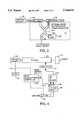
- FIG. 1helps in understanding this problem.
- FIG. 1is a comparison of the rise in beam energy over the length of the accelerator for pulsed versus CW RF sources with a particle velocity overlay. From Equation (2), it is clear that the beam energy rises linearly with length and the slope is set by the average E field intensity acting over that length.
- Line 10represents the rise in beam energy for a pulsed RF source whereas line 12 represents the rise in beam energy for a CW RF source.
- the higher beam energy at the output (line 14) for the pulsed RF sourceresults because of the higher average power of pulsed RF sources resulting in higher average E field intensity.
- Dashed line 16represents an overlay illustrating low particle velocity varies over the length of the accelerator. Particle velocity is very low and remains quite low for the majority of the length of the accelerator assuming a particle beam energy at the input of about 12 KeV and an output beam energy of 1 MeV, which, for electrons, translates to input particle velocities of about 0.2 C and an output velocity of about 0.92 C. The reason for this nonlinear velocity increase lies in the mathematical relationships governing motion of a charged particle in an electric field. Velocity of a charged particle after traversing a segment of E field of potential difference V is:
- the velocity characteristic symbolized by line 16 in FIG. 1is a square low relationship with the velocity growing as the square of the distance travelled.
- the ideais to synchronize the passage of particles through gaps of a coaxial system of cylindrical electrodes or in the electric field of an electromagnetic standing wave or a travelling wave such that the E field variations in a particular spatial area of the accelerator are such as to accelerate the particle as it passes through that spatial area.
- a structure using a single E 010 type cavity coupled to a conventional side coupled accelerator structure using three banana shaped coupling slots in the iris separating the E 010 type cavity from the rest of the structurewas built with a pulsed RF source in 1993 for a company called Intraop.
- This structurerequired a specific electric field configuration in the E 010 type cavity between the injection point and the first iris of the particles to work properly.
- This specific field configurationis difficult to model and it makes the output beam characteristics more sensitive to the field amplitude in the first E 010 type cavity than is the case for the invention described herein.
- This electric field configuration from the Intraop structureis not required in the invention described herein.
- the invention described hereincan achieve high output beam energy efficiently using a CW RF source even though the velocities of the injected particles is lower than can be efficiently accelerated using pulsed RF sources.
- the Intraop structurecannot use a CW source because the cavity parameters are not correct for such a low amplitude power source as a CW RF source.
- a high output beam energyis achieved using a low amplitude CW RF source and a low particle input injection velocity.
- This resultis achieved by coupling a charged particle source to the input of an RF linear accelerator having two different sections each of which is comprised of multiple acceleration cavities coupled by coupling cavities.
- the two sections of the acceleratorare coupled by a phase shifting coupler to establish accelerated particles leaving the first section on the E field of the second section in the proper phase relationship to continue the acceleration.
- Both sections of the acceleratorresonate with RF energy supplied by either a CW or pulsed RF source.
- the fact that the RF sourcecan be a low amplitude CW source without degrading the performance of the accelerator is an important aspect of the invention.
- the first section of the acceleratoris specially designed to be able to accelerate low velocity particles having velocities in the range from 0.1 C to 0.5 C using a CW source. In the case of electrons, the output energy from the first section is about 80 KeV.
- the second section of the acceleratoris designed to accelerate particles having velocities from 0.5 C to relativistic velocities. The output energy of particles from the second section can be any value typically from 1-20 MeV.
- FIG. 1is a diagram showing the principal difference in the linear rise in energy of particles in RF pulsed LINACs versus RF CW LINACs.
- FIG. 2is a cross-sectional diagram of an RF linear accelerator according to the teachings of the invention.
- FIG. 3is a schematic view of an alternative embodiment where a power splitter is used to couple CW or low pulse amplitude RF into an RF LINAC comprised of a low velocity section and a high velocity section.
- FIG. 4is a block diagram of an RF LINAC with a CW RF source that is duty cycle controlled by a beam energy/power controller.
- FIG. 2there is shown a cross-sectional view of an RF linear accelerator according to the teaching of the invention.
- the acceleratoriscomprised of a first, low-velocity section comprising one or more resonatorcavities.
- a first, low-velocity sectioncomprising one or more resonatorcavities.
- three resonator cavities 12, 14 and 16 to the left of coupling, phase-shifting device 11are shown, and a second, high-velocity section comprising three resonator cavities 18, 20 and 22 to the right of coupling, phase-shifting device 11.
- these two sectionswill be referred to as the low velocity accelerator andthe high velocity accelerator, respectively.
- All the resonator cavities of the low velocity and high velocity acceleratorsare cylindrical cavities defined by end walls with holes in the center for passage of the accelerated particle beam 24.
- these end wallswill be referred to as irises.
- a charged particle source 26introduces charged particles such as electronsor protons into the first accelerator cavity 12 of the low velocity section.
- the charged particle sourceis powered by a high voltage source 28. Since the low velocity section is capable of efficiently accelerating charged particles in the low velocity range from 0.1 C to 0.5 C with a CW RF source, the charged particles input by the charged particle source 26 do not need to be very energetic. Therefore, the charged particle source can be any of a plurality of different, known sources capable of supplyingcharged particles at a velocity of about 0.1 C.
- a gridded electron gunallowing grid control or grid modulation of the input beam is an example of one such source 26 and is preferred.
- the low velocity sectionhas the same general structural and physical properties defined in Russian Patent 1577678 field Dec. 1, 1988 and issuedMar. 8, 1990, the contents of which are hereby incorporated by reference.
- the basic idea behind the low velocity sectionis to couple together a series of Alvarez-type accelerator cavities through phase shifting or coupling cavities.
- Each of cavities 12, 14 and 16is cylindrical and has adrift tube in the center centered on the particle beam axis such that the beam passes the drift tube.
- cavity 12has a drift tube 30
- cavity 14has drift tube 32
- cavity 16has drift tube 34 therein.
- the purpose of the drift tubesis to provide a shield for the traveling particles in the portions of the cavity in which they find themselves whenvariations in the E field of the TM 010 mode excited by RF source 36 inthe region of the drift tube would cause deceleration.
- ⁇the average velocity of the charged particles in the cavity in meters per second divided by the velocity of light in vacuum
- ⁇ Othe wavelength of the RF excitation energy from RF source 36.
- the drift tubes 30, 32 and 34each have a length set according to Equation (7) below (in the preferred embodiment):
- Dthe length of the drift tube and ⁇ and ⁇ O are as definedfor Equation (6).
- the best length for the drift tubeis 0.5( ⁇ ⁇ O ).
- the drift tubescan have different lengths to optimize acceleration depending upon the transit time factor through the accelerating gaps. That is, the drift tubelength can be optimized based upon transit time factors. Basically, optimization of the acceleration process depends upon the intersection of two functions. One function relates the change of intensity of the electric field in the gaps to the changing length of the drift tube causing a changing acceleration gap distance between the end of the drift tube and the next iris or wall in the structure. The other function relates the transit time to the acceleration gap distance.
- drift tube length variationsBy varying the length of the drift tube to lengths slightly longer or shorter than 0.5( ⁇ ⁇ O ), it is possible to increase or decrease the acceleration that occurs in the gap from the amount of acceleration that occurs with the drift tube length set at 0.5( ⁇ ⁇ O ). In fact, drift tube length variations greater than ⁇ 0.15( ⁇ ⁇ O ) still fall within the teachings of the invention dependingupon the application to which the output beam will be put.
- the lengthof the Alvarez cavitiescan be set to any length, i.e., any number of complete cycles of the standing wave can be included within the confines of the cavity. In the case where more than one standing wave peak is included within the cavity, an appropriate number of drift tubes must be included in the cavity for shielding the particles from the fields at certain locations as is done in any Alvarez cavity.
- excitation energy wavelength and cavity/drift tube dimensionsare related as defined in Equations (6) and (7), synchronism between the movement of the particles and the RF field variations is achieved to provide acceleration.
- the structure of the low velocity sectionis set according to Equations (6) and (7) such that, within the adjacent gaps of each acceleration cavity separated by a drift tube, the RF fields oscillate in a co-phase relation.
- the fields in adjacent acceleration cavities separated by coupling cavities 40 and 42oscillate in an antiphase relationship.
- thecharged particlesfly through the adjacent acceleration cavities (sometimesalso referred to herein as resonators), they interact with the axial component of the electric field and acquire energy therefrom and pick up velocity.
- the drift tubesmay be supported in the centers of theresonators by disks. These disks have magnetic field coupling slots formed therein outside the position of the drift tube to provide a strong coupling for the fields.
- the low velocity and high velocity structures in FIG. 2are shown as having resonators 12, 14, 16, 18, 20 and 22 side coupled by coupling cavities 40, 42, 46 and 48, and phase shifting, coupling device 11, those skilled in the art will appreciate that the structure could also be on-axis coupled.
- the purpose of the coupling cavitiesis to act as spacers/phase changers such that the charged particles enter each acceleration gap in a resonator in the proper phase of the RF field variations in that gap so as to be further accelerated.
- the phase shift provided by the coupling cavities 40 and 42is ⁇ /2 or 90° so as to obtain a phase shift of ⁇ or 180° between adjacent accelerating cavities.
- the orientation of the axial components of the E fields in the low velocity structure acceleration gapsat a particular instant in timeis represented by arrows such as arrows 50,52 and 54 in FIG. 2.
- arrows 50,52 and 54the orientation of these arrows is reversed.
- the purpose of sizing the cavities and drift tubes in accordancewith the velocity of the particles and the wavelength of the RF excitation energy and using coupling cavities between resonatorsis to maintain synchronization.
- the charged particlesare accelerated in gaps 56and 58 by the left-to-right orientation of the E field and are shielded from deceleration by an E field from right to left in the center of the resonator 12 by drift tube 30.
- the particlesAfter the particles pass through gaps 56 and 58 and drift tube 30, they enter gap 60 in resonator 14.
- the purpose of coupling cavity 40is to insure that there is a sufficient phase changebetween gap 58 and gap 60 ( ⁇ /2 or 90°) such that by the instant the charged particles enter gap 60, the orientation of the E field in gap 60 will have reversed itself from that represented by arrow 52 and will beoriented from left to right.
- Phase change in an RF LINACis achieved by adding distance into the RF pathsince the TM 010 mode is basically a standing wave.
- Side couplingis preferred to on-axis coupling because it shortens the overall accelerator length while still achieving the desired phase change between each resonator. Shorter accelerators are cheaper to build since less shielding is required and fewer components are necessary. Shielding is required for all accelerators and it is expensive to build.
- Side couplingadds distanceto the path the RF sees while not adding distance to the path the beam travels. Since it is only necessary to add distance to the RF path to achieve the desired phase change, side coupling works.
- the dimensions of the coupling cavitiesare established by choosing the right resonant frequency of the coupling cavity to provide a ⁇ /2 phase shift per cavity so as to provide a ⁇ phase shift per accelerator cavity, and to provide proper mode separation.
- Shunt impedanceis a factor which characterizes acceleration efficiency, and it depends upon many factors, one of which is the number of walls per unit length of the beam path. If the coupling cavities are on-axis, the number of walls per unit length increases thereby lowering the shunt impedance and degrading the performance of the accelerator somewhat.
- the coupling device 11functions to change the RF path length sufficiently such that accelerated particles leaving resonator 16, the last resonator in the low velocity section, enter resonator 18 of the standing wave high velocity RF LINAC in proper phase with the RF field oscillations in cavity18 so as to be further accelerated (for maximum acceleration applications).
- the coupling device 11can also be placed between two of the high speed type cavities so as to divide the accelerator into two sections, thesection to the left of the coupler being called the low speed section but actually being comprised of two different types of accelerators cavities some of which include drift tubes and some of which do not.
- Coupling device 11canbe implemented using any microwave transmitter such as a coupling cavity, aregulated phase shifter and/or attenuator or a power splitter such as a power splitter.
- the power splitter embodiment for coupler 11is shown in FIG. 3. Any microwave transmitting device which can optimize the power/phase ratio between the low velocity and high velocity sections of the accelerator will suffice.
- a power splitter 104combined with an optional phase shifter and/orpower regulator 110 in one branch of the power splitter can be used to control the output beam parameters.
- Variable phase shifter 11can either maximize the acceleration or "detune" the phase of the fields in the high speed accelerator such that charged particles do not arrive precisely in synchronization with the maximum amplitude E field in resonator 18.
- a variable phase shifteris not the preferred way of controlling output beampower though because of "energy spread", i.e., the fact that not all the particles entering the first cavity of the high speed LINAC have the same energy.
- element 110be a phase shifter to provide the proper phase shift between the last cavity 16 of the low speed LINAC 100 and the first cavity 18 of the high speed LINAC, and then use a power regulator to control the beam power.
- the power regulator portion of element 110alters the amplitude of the RF excitation entering the high speed LINAC section 102 thereby causing a degree of acceleration of all particles, regardless of their energies, which varies with the amplitude of the RF excitation in the high speed LINAC.
- the optional phase shifter and/or power regulator 110can vary power into the high speed accelerator section thereby changing the output beam parameters. This is useful in medical and many other applications. For example, in medical applications where tumors are being irradiated and the beam energy must be precisely set to control the beam penetration through the body so as to only reach the tumor being irradiated and not healthy tissue beyond the tumor.
- FIG. 3is an RF linear accelerator comprised of a low velocity LINAC section 100 and a high velocity RF LINACsection 102 each fed by a single RF source 36 through a power splitter 104.
- the high and low velocity linear accelerators and the RF sourceare of the same structure as previously discussed as is the particle source 26.
- An RFload 106 having the characteristic impedance of the resonatorsis coupled to one branch of the power splitter 104 to absorb reflected power.
- the power splitterallows RF power from the source to be split between two waveguide sections coupled to the low velocity and high velocity sections respectively in a predetermined and, in some embodiments, variable ratio.
- the power splitteris also used to control the relative phase shift between the output of the low velocity RF LINAC and the input of the high velocity LINAC, and this phase shift can be made variable in some embodiments to provide the ability to modulate the beam power.
- the relative RF power fed to each of sections 100 and 102 as well as the relative phase relationship between the output of section 100 and the input of section 102could be regulated in addition to being variable witha suitable, known power splitter structure.
- the high velocity section of the acceleratorwould not be efficient in accelerating the low velocity particles injected by the charged particle source 26. This is because the resonator cavities 18, 20 and 22 would haveto be much shorter to maintain synchronization thereby bringing the end walls of the cavities much closer together. This would raise the number ofwalls per unit length along the beam axis to a higher number thereby increasing skin effect losses and lowering the shunt impedance and Q factor. Lower Q factor translates to lower E field intensity and lower acceleration per unit length, and this is true with both pulsed and CW RF sources.
- the accelerator structure of FIG. 2accelerates the low velocity particles with a structure that is efficient in the 0.1 C to 0.5 C range using a CW RF source and injects the accelerated particles travelling at 0.5 C into the conventional high velocity structure in the proper phase to further accelerate them using the same CW RF source used by the low velocity structure.
- Resonators 18, 20 and 22are of conventional design well known to those skilled in the art and will not befurther described here. Although side coupling is shown and preferred for the high velocity section, on-axis coupling could also be used.
- RF linear acceleratorsare described in the following references, all of which are hereby incorporated by reference.
- the RF source 36is preferably a CW microwave source, but in alternative embodiments, it could also be a low peak power pulsed source. Low peak power pulsed sources are not as expensive as high peak power pulsed RF sources.
- the RF sourceis powered by a high voltage power supply66 which can also include a modulator if pulsed power is used.
- the high voltage supplyreceives power from the A.C. power lines 68 through switch 70.
- Switch 70is opened and closed by a beam power controller 71. This beam power controller also controls the opened or closed state of a switch73 that enables and disables the charged particle sources 26 by controllingthe power supplied thereto.
- the beam power controllercan be operated to control the average beam power by controlling and synchronizing duty cycles of the charged particle source 26 and the RF source 36.
- intermittent pulsed operationcan be achieved by the beam power controller simultaneously closing switches 70 and 73 to fill the accelerator with RF energy and simultaneously inject charged particles into the accelerator.
- the switches 70 and 73are triacs, and the beam power controller can be a computer or any other circuit that turns both switches on in accordance with a duty cycle to achieve the desired output beam power.
- the beam powercontrollercan be more sophisticated in turning on switch 70 first, and then waiting some short time while the cavities fill with RF power and then turning on switch 73. Since the charged particles are accelerated mainly during the peaks of the RF power pulses, injection is done only during these times.
- the beam power controller 71 and switches 70 and 73represent an optional structure and, are not required to practice the basic structure of the invention of two LINACs which are structured to each accelerate different speed particles using a shared CW RF power source.
- the presence of the beam power controller 71 and switches 70 and 73gives the system added utility however in several respects.
- the beam power controllerby enabling modulation of the duty cycles of the RF power source and the charged particle injection source enables control of the average beam power.
- average beam poweris proportional to average beam current. Since the charged particle source is turned on by the beam power controller only when the RF source is simultaneously turned on, average beam current is altered when the dutycycle is altered. Average beam power is proportional to average beam current times the beam voltage which is a function of the distance over which charged particles are moved in an electric field, the electric fieldintensity and the charge of the particle. Average beam current is a function of the number of charged particles injected per unit time times the percentage of the total time the charged particle source is enabled, i.e., the duty cycle of the charged particle source. Therefore, by altering the duty cycle of the charged particle source and the RF source, the average beam current and average beam power can be precisely controlled. This has important implications in many applications for charged particle accelerators.
- the second advantage of using the beam power controller, controllable beam energyalso has important implications in that it allows the LINAC to be used for some applications which it would not otherwise be useable for with a CW RF source. Specifically, when CW RF power sources are operated intermittently, the amplitude of the RF excitation waveform can be increased during the "on" portion of the duty cycle beyond the amplitude that would be allowable during continuous CW operation. This is because the components of the RF power source and high voltage power supply have the duration of the "off" portion of the duty cycle to cool off.
- the third advantage of greater accelerator efficiency than pulsed RF sourceLINACsfollows from the fact that LINAC efficiency is proportional to beam power divided by RF source power. Because the relative percentage of the total "on" time represented by the "fill” and “decay” times is less in a CW LINAC operated intermittently than in a pulsed RF source LINAC, efficiency is greater. This is because pulsed RF LINACs have very short pulses, typically measured in microseconds, compared to the pulse times ofintermittently operated CW LINACs which are typically measured in milliseconds. Because the "fill” and “decay” times is approximately the same in both types of LINACs, the efficiency increase in the intermittently operated CW RF source LINAC is inevitable.
- the RF sourcefeeds the accelerator structure through an optional circulator 72 and a waveguide 74.
- the RF poweris shown in FIG. 2as being injected into the first cavity of the high speed section, the RF power can also be injected into any other of the cavities in either the low speed or high speed sections because the RF power redistributes itselfin accordance with the coupling between the cavities.
- Use of a circulatoris preferred because it prevents reflected power from being coupled back into the RF source 36 especially when arcing occurs in the LINAC. Arcing is not as common when the accelerator is well processed, but if arcing occurs, without a circulator, the reflected power can destroy the magnetron.
- the circulatorcanbe eliminated, but in the preferred embodiment, it is present to protect the magnetron because arcing can occur even in a well processed LINAC.
- Theprocessing techniques for building the LINACare not part of the invention,and any well known methodology for building the structures of FIGS. 2 and 3can be used to practice the invention.
- the inventionlies in the structuresof the accelerator cavities and their relationship to each other which provides the advantage of being able to use CW RF sources to accelerate low velocity particles efficiently.
- the microwave source 36is preferably a magnetron, but could also be a Klystron or travelling wave tube or other known microwave sources. CW magnetrons are available at 50 kW microwave power in the 3 GHz frequency range.
- the RF source 36can be coupled to any of the resonator cavities ineither the high or low velocity structures.
- the RF power sourcecan also becoupled to the accelerator through a power splitter as described in reference 3 above.
- Switch 70could be a fast switch such as a triac to convert CW operation into pulsed operation using long pulses when pulse rise and fall times arenot of great importance.
- a modulator for block 66is preferred for low power pulsed operation.
- a beam shaping device 76This device can take the form of a magnetic or electrical lens, a scatterer, a quadruple, a scanneror a drift space.
- the beammay be applied to an output device 78 through, for example, a beam fan 80.
- Typical output devicesinclude x-ray converters, aluminum foil, neutron converters, etc.
- the RF linear accelerator of the structure of FIG. 2has the following properties.
- FIG. 4there is shown a block diagram of a duty cycle controlled RF LINAC using a CW RF source which has several advantages overconventional CW RF LINACs.
- the RF LINAC 120 and its charged particle source122can be any conventional RF LINAC structure and charged particle source which is compatible with the lower amplitudes of CW RF sources.
- the RF LINAC and charged particle sourcemay have the structure shown in FIG. 2 or any of the alternative forms thereof identified herein.
- a CW RF source 124is powered by a high voltage power supply 126.
- the high voltage supplyreceives power from the A.C. power lines 68 through switch 70.
- Switch 70is opened and closed by a beam power/energy controller 128.
- This beam power/energy controller 128also controls the opened or closed state of a switch 73 that enables and disables the charged particle source122 by controlling the power supplied thereto from a high voltage supply 28.
- the beam power/energy controller 128can be operated to control the average beam power by controlling and synchronizing duty cycles of the charged particle source 122 and the CW RF source 124. In other words, intermittent pulsed operation can be achieved by using the beam power/energy controller to simultaneously close switches 70 and 73 to fillthe accelerator with RF energy and simultaneously inject charged particles into the accelerator.
- the beam energy/power controller 128can also be used to increase or decrease the output beam energy by controlling the amplitude of the high voltage supplied to the CW RF source124 on lines 130 via a beam energy control signal on line 132.
- This controlsignal controlsis coupled to a voltage regulator in the high voltage powersupply 126 so as to control the output voltage on lines 130.
- the high voltage on lines 130control the cathode-to-anode voltage applied to a magnetron in CW RF source 124. Raising the cathode-to-anode voltage causesthe magnitude of the RF excitation energy supplied to the RF LINAC 120 through circulator 72 to increase thereby increasing the output beam energy.
- the beam energy/power controller 128simultaneously decreases the duty cycles of the CW RF source 124 and the particle source 122 when the output beam energy is raised so that the average beam power stays within the design limits of the cooling system (not shown) that cools various components in the system of FIG. 4 such as the RF LINAC 120, target 134 and CW RF source 124.
- the switches 70 and 73are triacs, and the beam power/energy controller 128 can be a computer or any other circuit that turns both switches on in accordance with a duty cycle to achieve thedesired output beam power.
- the controller 128can be more sophisticated in turning on switch 70 first, and then waiting some short time while the cavities fill with RF power and then turning on switch 73. Since the charged particles are accelerated mainly during the peaks of the RF power pulses, injection is done only during these times.
- the beam power/energy controller 128,by enabling modulation of the duty cycles of the CW RF power source 124 and the charged particle injection source 122 enables control of the average beam power.
- Third, operating the accelerator with a CW RF source which is enabled intermittently with RF pulse lengths that are very long compared to the typical pulse lengths of pulsed RF sourcesincreases the efficiency of the accelerator. This is because the "fill time” and "decay time” which translate roughly to the rise and fall times of the RF pulses.
- average beam poweris proportional to average beam current. Since the charged particle source is turned on by the beam power controller only when the RF source is simultaneously turned on, average beam current is altered when the dutycycle is altered. Average beam power is proportional to average beam current times the beam voltage which is a function of the distance over which charged particles are moved in an electric field, the electric fieldintensity and the charge of the particle. Average beam current is a function of the number of charged particles injected per unit time times the percentage of the total time the charged particle source is enabled, i.e., the duty cycle of the charged particle source. Therefore, by altering the duty cycle of the charged particle source and the RF source, the average beam current and average beam power can be precisely controlled. This has important implications in many applications for charged particle accelerators.
- the second advantage of using the beam power controller, controllable beam energyalso has important implications in that it allows the LINAC to be used for some applications which it would not otherwise be useable for with a CW RF source. Specifically, when CW RF power sources are operated intermittently, the amplitude of the RF excitation waveform can be increased during the "on" portion of the duty cycle beyond the amplitude that would be allowable during continuous CW operation. This is because the components of the RF power source and high voltage power supply have the duration of the "off" portion of the duty cycle to cool off.
- the third advantage of greater accelerator efficiency than pulsed RF sourceLINACsfollows from the fact that LINAC efficiency is proportional to beam power divided by RF source power. Because the relative percentage of the total "on" time represented by the "fill” and “decay” times is less in a CW LINAC operated intermittently than in a pulsed RF source LINAC, efficiency is greater. This is because pulsed RF LINACs have very short pulses, typically measured in microseconds, compared to the pulse times ofintermittently operated CW LINACs which are typically measured in milliseconds. Because the "fill” and “decay” times is approximately the same in both types of LINACs, the efficiency increase in the intermittently operated CW RF source LINAC is inevitable.
Landscapes
- Physics & Mathematics (AREA)
- Engineering & Computer Science (AREA)
- Plasma & Fusion (AREA)
- Spectroscopy & Molecular Physics (AREA)
- Particle Accelerators (AREA)
Abstract
Description
P.sub.B =WI.sub.OV ( 1)
W=eEL (2)
eV=mc.sup.2 γ (5)
D=0.5±0.15(β λ.sub.O) (7)
______________________________________ Loaded Electron Energy W.sub.OUT 1 MeV Average Beam CurrentI.sub.AV 10 mA Beam Power P.sub.b 10 kW RF Power SourceP.sub.O 30 kW Magnetron CW Injection Energy W.sub.O 10-20 KeV Efficiency ##STR1## 30% Length of RF LINAC Structure 1 Meter Shunt ImpedanceR.sub.S 100 MOhm/m Q.sub.O 16,000 ______________________________________
Claims (26)
D=(0.5±0.15)β λ.sub.O
D=(0.5±0.15)β λ.sub.O
D=(0.5±0.15)β λ.sub.O
D=(0.5±0.15)β λ.sub.O
Priority Applications (3)
| Application Number | Priority Date | Filing Date | Title |
|---|---|---|---|
| US08/764,535US5744919A (en) | 1996-12-12 | 1996-12-12 | CW particle accelerator with low particle injection velocity |
| PCT/US1997/022880WO1998028951A2 (en) | 1996-12-12 | 1997-12-12 | Cw particle accelerator with low particle injection velocity |
| AU56990/98AAU5699098A (en) | 1996-12-12 | 1997-12-12 | Cw particle accelerator with low particle injection velocity |
Applications Claiming Priority (1)
| Application Number | Priority Date | Filing Date | Title |
|---|---|---|---|
| US08/764,535US5744919A (en) | 1996-12-12 | 1996-12-12 | CW particle accelerator with low particle injection velocity |
Publications (1)
| Publication Number | Publication Date |
|---|---|
| US5744919Atrue US5744919A (en) | 1998-04-28 |
Family
ID=25070989
Family Applications (1)
| Application Number | Title | Priority Date | Filing Date |
|---|---|---|---|
| US08/764,535Expired - LifetimeUS5744919A (en) | 1996-12-12 | 1996-12-12 | CW particle accelerator with low particle injection velocity |
Country Status (3)
| Country | Link |
|---|---|
| US (1) | US5744919A (en) |
| AU (1) | AU5699098A (en) |
| WO (1) | WO1998028951A2 (en) |
Cited By (118)
| Publication number | Priority date | Publication date | Assignee | Title |
|---|---|---|---|---|
| US5969367A (en)* | 1996-08-30 | 1999-10-19 | Hitachi, Ltd | Charged particle beam apparatus and method for operating the same |
| US6326861B1 (en) | 1999-07-16 | 2001-12-04 | Feltech Corporation | Method for generating a train of fast electrical pulses and application to the acceleration of particles |
| RU2183390C2 (en)* | 2000-09-04 | 2002-06-10 | Московский государственный инженерно-физический институт (технический университет) | Heavy-current linear accelerator of ions |
| US6423976B1 (en)* | 1999-05-28 | 2002-07-23 | Applied Materials, Inc. | Ion implanter and a method of implanting ions |
| WO2004030425A3 (en)* | 2002-09-27 | 2004-07-08 | Scantech Holdings Llc | Multi-section particle accelerator with controlled beam current |
| US6844689B1 (en)* | 2003-08-29 | 2005-01-18 | Mevex Corporation | Multiple beam linear accelerator system |
| US20050057198A1 (en)* | 2003-08-22 | 2005-03-17 | Hanna Samy M. | Electronic energy switch for particle accelerator |
| US20050117683A1 (en)* | 2000-02-10 | 2005-06-02 | Andrey Mishin | Multiple energy x-ray source for security applications |
| US20060006809A1 (en)* | 2004-07-08 | 2006-01-12 | Kenneth Whitham | Distributed RF sources for medical RF accelerator |
| RU2282955C2 (en)* | 2004-05-13 | 2006-08-27 | Виталий Михайлович Пироженко | Linear accelerator of electrons |
| US20060216940A1 (en)* | 2004-08-13 | 2006-09-28 | Virgin Islands Microsystems, Inc. | Methods of producing structures for electron beam induced resonance using plating and/or etching |
| US7116064B1 (en)* | 2004-02-27 | 2006-10-03 | Advanced Energy Systems, Inc. | Axisymmetric emittance-compensated electron gun |
| US7166973B1 (en)* | 2005-09-13 | 2007-01-23 | Jefferson Science Associates Llc | Use of incomplete energy recovery for the energy compression of large energy spread charged particle beams |
| US20070034518A1 (en)* | 2005-08-15 | 2007-02-15 | Virgin Islands Microsystems, Inc. | Method of patterning ultra-small structures |
| US20070075326A1 (en)* | 2005-09-30 | 2007-04-05 | Virgin Islands Microsystems, Inc. | Diamond field emmission tip and a method of formation |
| US20070154846A1 (en)* | 2006-01-05 | 2007-07-05 | Virgin Islands Microsystems, Inc. | Switching micro-resonant structures using at least one director |
| US20070152781A1 (en)* | 2006-01-05 | 2007-07-05 | Virgin Islands Microsystems, Inc. | Switching micro-resonant structures by modulating a beam of charged particles |
| US20070152938A1 (en)* | 2006-01-05 | 2007-07-05 | Virgin Islands Microsystems, Inc. | Resonant structure-based display |
| US20070152176A1 (en)* | 2006-01-05 | 2007-07-05 | Virgin Islands Microsystems, Inc. | Selectable frequency light emitter |
| US20070170370A1 (en)* | 2005-09-30 | 2007-07-26 | Virgin Islands Microsystems, Inc. | Structures and methods for coupling energy from an electromagnetic wave |
| US20070176689A1 (en)* | 2006-01-31 | 2007-08-02 | Nec Microwave Tube, Ltd. | Power supply apparatus and high frequency circuit system |
| US20070190794A1 (en)* | 2006-02-10 | 2007-08-16 | Virgin Islands Microsystems, Inc. | Conductive polymers for the electroplating |
| US20070200910A1 (en)* | 2006-02-28 | 2007-08-30 | Virgin Islands Microsystems, Inc. | Electro-photographic devices incorporating ultra-small resonant structures |
| US20070200784A1 (en)* | 2006-02-28 | 2007-08-30 | Virgin Islands Microsystems, Inc. | Integrated filter in antenna-based detector |
| US20070200063A1 (en)* | 2006-02-28 | 2007-08-30 | Virgin Islands Microsystems, Inc. | Wafer-level testing of light-emitting resonant structures |
| US20070200071A1 (en)* | 2006-02-28 | 2007-08-30 | Virgin Islands Microsystems, Inc. | Coupling output from a micro resonator to a plasmon transmission line |
| US20070235651A1 (en)* | 2006-04-10 | 2007-10-11 | Virgin Island Microsystems, Inc. | Resonant detector for optical signals |
| US7282776B2 (en) | 2006-02-09 | 2007-10-16 | Virgin Islands Microsystems, Inc. | Method and structure for coupling two microcircuits |
| US20070252089A1 (en)* | 2006-04-26 | 2007-11-01 | Virgin Islands Microsystems, Inc. | Charged particle acceleration apparatus and method |
| US20070253535A1 (en)* | 2006-04-26 | 2007-11-01 | Virgin Islands Microsystems, Inc. | Source of x-rays |
| US20070258675A1 (en)* | 2006-05-05 | 2007-11-08 | Virgin Islands Microsystems, Inc. | Multiplexed optical communication between chips on a multi-chip module |
| US20070258720A1 (en)* | 2006-05-05 | 2007-11-08 | Virgin Islands Microsystems, Inc. | Inter-chip optical communication |
| US20070257273A1 (en)* | 2006-05-05 | 2007-11-08 | Virgin Island Microsystems, Inc. | Novel optical cover for optical chip |
| US20070258690A1 (en)* | 2006-05-05 | 2007-11-08 | Virgin Islands Microsystems, Inc. | Integration of electromagnetic detector on integrated chip |
| US20070258492A1 (en)* | 2006-05-05 | 2007-11-08 | Virgin Islands Microsystems, Inc. | Light-emitting resonant structure driving raman laser |
| US20070257739A1 (en)* | 2006-05-05 | 2007-11-08 | Virgin Islands Microsystems, Inc. | Local plane array incorporating ultra-small resonant structures |
| US20070258146A1 (en)* | 2006-05-05 | 2007-11-08 | Virgin Islands Microsystems, Inc. | Reflecting filtering cover |
| US20070258689A1 (en)* | 2006-05-05 | 2007-11-08 | Virgin Islands Microsystems, Inc. | Coupling electromagnetic wave through microcircuit |
| US20070257199A1 (en)* | 2006-05-05 | 2007-11-08 | Virgin Islands Microsystems, Inc. | Heterodyne receiver using resonant structures |
| US20070257621A1 (en)* | 2006-05-05 | 2007-11-08 | Virgin Islands Microsystems, Inc. | Plated multi-faceted reflector |
| US20070257738A1 (en)* | 2006-05-05 | 2007-11-08 | Virgin Islands Microsystems, Inc. | Top metal layer shield for ultra-small resonant structures |
| US20070256472A1 (en)* | 2006-05-05 | 2007-11-08 | Virgin Islands Microsystems, Inc. | SEM test apparatus |
| US20070257749A1 (en)* | 2006-05-05 | 2007-11-08 | Virgin Islands Microsystems, Inc. | Coupling a signal through a window |
| US20070259641A1 (en)* | 2006-05-05 | 2007-11-08 | Virgin Islands Microsystems, Inc. | Heterodyne receiver array using resonant structures |
| US20070257622A1 (en)* | 2006-05-05 | 2007-11-08 | Virgin Islands Microsystems, Inc. | Coupling energy in a plasmon wave to an electron beam |
| US20070257328A1 (en)* | 2006-05-05 | 2007-11-08 | Virgin Islands Microsystems, Inc. | Detecting plasmons using a metallurgical junction |
| US20070257620A1 (en)* | 2006-05-05 | 2007-11-08 | Virgin Islands Microsystems, Inc. | Coupled nano-resonating energy emitting structures |
| US20070257619A1 (en)* | 2006-05-05 | 2007-11-08 | Virgin Islands Microsystems, Inc. | Selectable frequency light emitter |
| US20070257206A1 (en)* | 2006-05-05 | 2007-11-08 | Virgin Islands Microsystems, Inc. | Transmission of data between microchips using a particle beam |
| US20070258126A1 (en)* | 2006-05-05 | 2007-11-08 | Virgin Islands Microsystems, Inc. | Electro-optical switching system and method |
| US20070259488A1 (en)* | 2006-05-05 | 2007-11-08 | Virgin Islands Microsystems, Inc. | Single layer construction for ultra small devices |
| US20070259465A1 (en)* | 2006-05-05 | 2007-11-08 | Virgin Islands Microsystems, Inc. | Integration of vacuum microelectronic device with integrated circuit |
| US20070264023A1 (en)* | 2006-04-26 | 2007-11-15 | Virgin Islands Microsystems, Inc. | Free space interchip communications |
| US20070264030A1 (en)* | 2006-04-26 | 2007-11-15 | Virgin Islands Microsystems, Inc. | Selectable frequency EMR emitter |
| WO2007134514A1 (en)* | 2006-05-19 | 2007-11-29 | Tsinghua University | Device method and material identifying system for producing x-ray having different energy |
| US20070272876A1 (en)* | 2006-05-26 | 2007-11-29 | Virgin Islands Microsystems, Inc. | Receiver array using shared electron beam |
| US20070274365A1 (en)* | 2006-05-26 | 2007-11-29 | Virgin Islands Microsystems, Inc. | Periodically complex resonant structures |
| US20070272931A1 (en)* | 2006-05-05 | 2007-11-29 | Virgin Islands Microsystems, Inc. | Methods, devices and systems producing illumination and effects |
| US20080001098A1 (en)* | 2006-06-28 | 2008-01-03 | Virgin Islands Microsystems, Inc. | Data on light bulb |
| US20080043910A1 (en)* | 2006-08-15 | 2008-02-21 | Tomotherapy Incorporated | Method and apparatus for stabilizing an energy source in a radiation delivery device |
| US20080069509A1 (en)* | 2006-09-19 | 2008-03-20 | Virgin Islands Microsystems, Inc. | Microcircuit using electromagnetic wave routing |
| US20080067941A1 (en)* | 2006-05-05 | 2008-03-20 | Virgin Islands Microsystems, Inc. | Shielding of integrated circuit package with high-permeability magnetic material |
| US20080067940A1 (en)* | 2006-05-05 | 2008-03-20 | Virgin Islands Microsystems, Inc. | Surface plasmon signal transmission |
| US20080073590A1 (en)* | 2006-09-22 | 2008-03-27 | Virgin Islands Microsystems, Inc. | Free electron oscillator |
| US20080083881A1 (en)* | 2006-05-15 | 2008-04-10 | Virgin Islands Microsystems, Inc. | Plasmon wave propagation devices and methods |
| US20080089481A1 (en)* | 2006-10-16 | 2008-04-17 | Oraya Therapeutics, Inc. | Portable orthovoltage radiotherapy |
| WO2008046262A1 (en)* | 2006-10-13 | 2008-04-24 | Nuctech Company Limited | Standing wave electron linear accelerator and installation and modulation device thereof |
| US20080129203A1 (en)* | 2006-11-30 | 2008-06-05 | Radiabeam Technologies, Llc | Method and apparatus for radio frequency cavity |
| US20080149828A1 (en)* | 2006-12-20 | 2008-06-26 | Virgin Islands Microsystems, Inc. | Low terahertz source and detector |
| US20080212738A1 (en)* | 2006-12-13 | 2008-09-04 | Oraya Therapeutics, Inc. | Orthovoltage radiotherapy |
| US20080296517A1 (en)* | 2005-12-14 | 2008-12-04 | Virgin Islands Microsystems, Inc. | Coupling light of light emitting resonator to waveguide |
| US20090072698A1 (en)* | 2007-06-19 | 2009-03-19 | Virgin Islands Microsystems, Inc. | Microwave coupled excitation of solid state resonant arrays |
| US20090140177A1 (en)* | 2007-10-12 | 2009-06-04 | David Whittum | Charged particle accelerators, radiation sources, system, and methods |
| US20090161826A1 (en)* | 2007-12-23 | 2009-06-25 | Oraya Therapeutics, Inc. | Methods and devices for orthovoltage ocular radiotherapy and treatment planning |
| US20090163898A1 (en)* | 2007-06-04 | 2009-06-25 | Oraya Therapeutics, Inc. | Method and device for ocular alignment and coupling of ocular structures |
| US20090161827A1 (en)* | 2007-12-23 | 2009-06-25 | Oraya Therapeutics, Inc. | Methods and devices for detecting, controlling, and predicting radiation delivery |
| US20090182312A1 (en)* | 2008-01-11 | 2009-07-16 | Oraya Therapeutics, Inc. | Device and assembly for positioning and stabilizing an eye |
| US20090290604A1 (en)* | 2006-04-26 | 2009-11-26 | Virgin Islands Microsystems, Inc. | Micro free electron laser (FEL) |
| US7656094B2 (en) | 2006-05-05 | 2010-02-02 | Virgin Islands Microsystems, Inc. | Electron accelerator for ultra-small resonant structures |
| US7718977B2 (en) | 2006-05-05 | 2010-05-18 | Virgin Island Microsystems, Inc. | Stray charged particle removal device |
| US20100207551A1 (en)* | 2009-01-22 | 2010-08-19 | Omega P-Inc. | Multi-mode, multi-frequency, two-beam accelerating device and method |
| US7791053B2 (en) | 2007-10-10 | 2010-09-07 | Virgin Islands Microsystems, Inc. | Depressed anode with plasmon-enabled devices such as ultra-small resonant structures |
| EP2296165A1 (en)* | 2009-09-14 | 2011-03-16 | L-3 Communications Corporation | Dual element switched electron gun |
| US20110062898A1 (en)* | 2009-09-14 | 2011-03-17 | Richard Brownell True | Dual element switched electron gun |
| DE102010042148A1 (en)* | 2010-10-07 | 2012-04-12 | Siemens Aktiengesellschaft | Method for exciting a vibration in a resonator |
| CN102550131A (en)* | 2009-10-02 | 2012-07-04 | 西门子公司 | Accelerator and method for controlling the accelerator |
| US20120200238A1 (en)* | 2009-08-21 | 2012-08-09 | Thales | Microwave Device for Accelerating Electrons |
| CN102769990A (en)* | 2011-05-04 | 2012-11-07 | 西门子公司 | linear accelerator |
| DE102011076262A1 (en)* | 2011-05-23 | 2012-11-29 | Siemens Aktiengesellschaft | Accelerator e.g. electron accelerator for medical application e.g. radiotherapy application, has filter provided between two stages having acceleration zones, for reducing width of energy distribution of particles |
| US8339071B2 (en)* | 2002-09-27 | 2012-12-25 | Scantech/Ibs Ip Holding Company, Llc | Particle accelerator having wide energy control range |
| US20130033201A1 (en)* | 2010-04-26 | 2013-02-07 | Quan Japan Co., Ltd. | Charged particle accelerator and charged particle acceleration method |
| US20130063052A1 (en)* | 2010-03-05 | 2013-03-14 | Accuray, Inc. | Interleaving multi-energy x-ray energy operation of a standing wave linear accelerator |
| US20130140454A1 (en)* | 2010-05-11 | 2013-06-06 | Dh Technologies Development Pte. Ltd. | Ion lens for reducing contaminant effects in an ion guide of a mass spectrometer |
| EP2750486A1 (en)* | 2012-12-28 | 2014-07-02 | Tsinghua University | Standing wave electron linear accelerator with continuously adjustable energy |
| US8837670B2 (en) | 2006-05-05 | 2014-09-16 | Rapiscan Systems, Inc. | Cargo inspection system |
| US8908831B2 (en) | 2011-02-08 | 2014-12-09 | Rapiscan Systems, Inc. | Covert surveillance using multi-modality sensing |
| US9052403B2 (en) | 2002-07-23 | 2015-06-09 | Rapiscan Systems, Inc. | Compact mobile cargo scanning system |
| US9218933B2 (en) | 2011-06-09 | 2015-12-22 | Rapidscan Systems, Inc. | Low-dose radiographic imaging system |
| US9223049B2 (en) | 2002-07-23 | 2015-12-29 | Rapiscan Systems, Inc. | Cargo scanning system with boom structure |
| US9223050B2 (en) | 2005-04-15 | 2015-12-29 | Rapiscan Systems, Inc. | X-ray imaging system having improved mobility |
| US9285498B2 (en) | 2003-06-20 | 2016-03-15 | Rapiscan Systems, Inc. | Relocatable X-ray imaging system and method for inspecting commercial vehicles and cargo containers |
| US9332624B2 (en) | 2008-05-20 | 2016-05-03 | Rapiscan Systems, Inc. | Gantry scanner systems |
| US20160174355A1 (en)* | 2012-10-17 | 2016-06-16 | Cornell University | Generation and acceleration of charged particles using compact devices and systems |
| US9443633B2 (en) | 2013-02-26 | 2016-09-13 | Accuray Incorporated | Electromagnetically actuated multi-leaf collimator |
| US9557427B2 (en) | 2014-01-08 | 2017-01-31 | Rapiscan Systems, Inc. | Thin gap chamber neutron detectors |
| US9625606B2 (en) | 2009-05-16 | 2017-04-18 | Rapiscan Systems, Inc. | Systems and methods for high-Z threat alarm resolution |
| US9655227B2 (en) | 2014-06-13 | 2017-05-16 | Jefferson Science Associates, Llc | Slot-coupled CW standing wave accelerating cavity |
| US9791590B2 (en) | 2013-01-31 | 2017-10-17 | Rapiscan Systems, Inc. | Portable security inspection system |
| US10568196B1 (en)* | 2016-11-21 | 2020-02-18 | Triad National Security, Llc | Compact, high-efficiency accelerators driven by low-voltage solid-state amplifiers |
| USRE48047E1 (en)* | 2004-07-21 | 2020-06-09 | Mevion Medical Systems, Inc. | Programmable radio frequency waveform generator for a synchrocyclotron |
| US10842012B2 (en)* | 2018-10-19 | 2020-11-17 | Aceleron, Inc. | Methods and systems for plasma self-compression |
| US20210195726A1 (en)* | 2019-12-12 | 2021-06-24 | James Andrew Leskosek | Linear accelerator using a stacked array of cyclotrons |
| CN113099601A (en)* | 2021-04-01 | 2021-07-09 | 中国工程物理研究院流体物理研究所 | Low-energy heavy ion accelerator and acceleration method |
| US11191148B2 (en)* | 2018-12-28 | 2021-11-30 | Shanghai United Imaging Healthcare Co., Ltd. | Accelerating apparatus for a radiation device |
| US11337298B2 (en)* | 2020-08-31 | 2022-05-17 | Chengdu Elekom Vacuum Electron Technology Co. Ltd | Radio frequency electron accelerator for local frequency modulation and frequency modulation method thereof |
| US20220174810A1 (en)* | 2020-12-01 | 2022-06-02 | Applied Materials, Inc. | Resonator, linear accelerator configuration and ion implantation system having toroidal resonator |
| US12225656B2 (en) | 2018-12-28 | 2025-02-11 | Shanghai United Imaging Healthcare Co., Ltd. | Accelerating apparatus for a radiation device |
| CN119743883A (en)* | 2025-03-04 | 2025-04-01 | 中国科学院近代物理研究所 | Linear accelerator based on high gradient traveling wave accelerating structure |
Families Citing this family (1)
| Publication number | Priority date | Publication date | Assignee | Title |
|---|---|---|---|---|
| DE102009032275A1 (en)* | 2009-07-08 | 2011-01-13 | Siemens Aktiengesellschaft | Accelerator system and method for adjusting a particle energy |
Citations (3)
| Publication number | Priority date | Publication date | Assignee | Title |
|---|---|---|---|---|
| US5021741A (en)* | 1990-04-12 | 1991-06-04 | Grumman Aerospace Corporation | Cast charged particle drift tube |
| US5179350A (en)* | 1991-08-07 | 1993-01-12 | Accsys Technology, Inc. | Drift tube linac with drift tube performance normalization and maximization |
| US5578909A (en)* | 1994-07-15 | 1996-11-26 | The Regents Of The Univ. Of California | Coupled-cavity drift-tube linac |
- 1996
- 1996-12-12USUS08/764,535patent/US5744919A/ennot_activeExpired - Lifetime
- 1997
- 1997-12-12WOPCT/US1997/022880patent/WO1998028951A2/enactiveApplication Filing
- 1997-12-12AUAU56990/98Apatent/AU5699098A/ennot_activeAbandoned
Patent Citations (3)
| Publication number | Priority date | Publication date | Assignee | Title |
|---|---|---|---|---|
| US5021741A (en)* | 1990-04-12 | 1991-06-04 | Grumman Aerospace Corporation | Cast charged particle drift tube |
| US5179350A (en)* | 1991-08-07 | 1993-01-12 | Accsys Technology, Inc. | Drift tube linac with drift tube performance normalization and maximization |
| US5578909A (en)* | 1994-07-15 | 1996-11-26 | The Regents Of The Univ. Of California | Coupled-cavity drift-tube linac |
Cited By (288)
| Publication number | Priority date | Publication date | Assignee | Title |
|---|---|---|---|---|
| US5969367A (en)* | 1996-08-30 | 1999-10-19 | Hitachi, Ltd | Charged particle beam apparatus and method for operating the same |
| US6316776B1 (en) | 1996-08-30 | 2001-11-13 | Hitachi, Ltd. | Charged particle beam apparatus and method for operating the same |
| EP1056113A3 (en)* | 1999-05-28 | 2007-02-28 | Applied Materials, Inc. | Ion implanter and a method of implanting ions |
| US6423976B1 (en)* | 1999-05-28 | 2002-07-23 | Applied Materials, Inc. | Ion implanter and a method of implanting ions |
| US6326861B1 (en) | 1999-07-16 | 2001-12-04 | Feltech Corporation | Method for generating a train of fast electrical pulses and application to the acceleration of particles |
| US20050117683A1 (en)* | 2000-02-10 | 2005-06-02 | Andrey Mishin | Multiple energy x-ray source for security applications |
| RU2183390C2 (en)* | 2000-09-04 | 2002-06-10 | Московский государственный инженерно-физический институт (технический университет) | Heavy-current linear accelerator of ions |
| US9052403B2 (en) | 2002-07-23 | 2015-06-09 | Rapiscan Systems, Inc. | Compact mobile cargo scanning system |
| US9223049B2 (en) | 2002-07-23 | 2015-12-29 | Rapiscan Systems, Inc. | Cargo scanning system with boom structure |
| US10007019B2 (en) | 2002-07-23 | 2018-06-26 | Rapiscan Systems, Inc. | Compact mobile cargo scanning system |
| US10670769B2 (en) | 2002-07-23 | 2020-06-02 | Rapiscan Systems, Inc. | Compact mobile cargo scanning system |
| US8339071B2 (en)* | 2002-09-27 | 2012-12-25 | Scantech/Ibs Ip Holding Company, Llc | Particle accelerator having wide energy control range |
| WO2004030425A3 (en)* | 2002-09-27 | 2004-07-08 | Scantech Holdings Llc | Multi-section particle accelerator with controlled beam current |
| US20050212465A1 (en)* | 2002-09-27 | 2005-09-29 | Zavadtsev Alexandre A | Multi-section particle accelerator with controlled beam current |
| US7208890B2 (en)* | 2002-09-27 | 2007-04-24 | Scan Tech Holdings, Llc | Multi-section particle accelerator with controlled beam current |
| US20080100236A1 (en)* | 2002-09-27 | 2008-05-01 | Scantech Holdings, Llc | Multi-section particle accelerator with controlled beam current |
| US9285498B2 (en) | 2003-06-20 | 2016-03-15 | Rapiscan Systems, Inc. | Relocatable X-ray imaging system and method for inspecting commercial vehicles and cargo containers |
| US20050057198A1 (en)* | 2003-08-22 | 2005-03-17 | Hanna Samy M. | Electronic energy switch for particle accelerator |
| US7112924B2 (en)* | 2003-08-22 | 2006-09-26 | Siemens Medical Solutions Usa, Inc. | Electronic energy switch for particle accelerator |
| US6844689B1 (en)* | 2003-08-29 | 2005-01-18 | Mevex Corporation | Multiple beam linear accelerator system |
| US7116064B1 (en)* | 2004-02-27 | 2006-10-03 | Advanced Energy Systems, Inc. | Axisymmetric emittance-compensated electron gun |
| RU2282955C2 (en)* | 2004-05-13 | 2006-08-27 | Виталий Михайлович Пироженко | Linear accelerator of electrons |
| US20060006809A1 (en)* | 2004-07-08 | 2006-01-12 | Kenneth Whitham | Distributed RF sources for medical RF accelerator |
| US7242158B2 (en)* | 2004-07-08 | 2007-07-10 | Siemens Medical Solutions Usa, Inc. | Distributed RF sources for medical RF accelerator |
| USRE48047E1 (en)* | 2004-07-21 | 2020-06-09 | Mevion Medical Systems, Inc. | Programmable radio frequency waveform generator for a synchrocyclotron |
| US20060216940A1 (en)* | 2004-08-13 | 2006-09-28 | Virgin Islands Microsystems, Inc. | Methods of producing structures for electron beam induced resonance using plating and/or etching |
| US7758739B2 (en) | 2004-08-13 | 2010-07-20 | Virgin Islands Microsystems, Inc. | Methods of producing structures for electron beam induced resonance using plating and/or etching |
| US9223050B2 (en) | 2005-04-15 | 2015-12-29 | Rapiscan Systems, Inc. | X-ray imaging system having improved mobility |
| US20070034518A1 (en)* | 2005-08-15 | 2007-02-15 | Virgin Islands Microsystems, Inc. | Method of patterning ultra-small structures |
| US7166973B1 (en)* | 2005-09-13 | 2007-01-23 | Jefferson Science Associates Llc | Use of incomplete energy recovery for the energy compression of large energy spread charged particle beams |
| US7791290B2 (en)* | 2005-09-30 | 2010-09-07 | Virgin Islands Microsystems, Inc. | Ultra-small resonating charged particle beam modulator |
| US7557365B2 (en) | 2005-09-30 | 2009-07-07 | Virgin Islands Microsystems, Inc. | Structures and methods for coupling energy from an electromagnetic wave |
| US20070075265A1 (en)* | 2005-09-30 | 2007-04-05 | Virgin Islands Microsystems, Inc. | Coupled nano-resonating energy emitting structures |
| US7791291B2 (en) | 2005-09-30 | 2010-09-07 | Virgin Islands Microsystems, Inc. | Diamond field emission tip and a method of formation |
| US20070085039A1 (en)* | 2005-09-30 | 2007-04-19 | Virgin Islands Microsystems, Inc. | Structures and methods for coupling energy from an electromagnetic wave |
| US20070170370A1 (en)* | 2005-09-30 | 2007-07-26 | Virgin Islands Microsystems, Inc. | Structures and methods for coupling energy from an electromagnetic wave |
| US7253426B2 (en) | 2005-09-30 | 2007-08-07 | Virgin Islands Microsystems, Inc. | Structures and methods for coupling energy from an electromagnetic wave |
| US7626179B2 (en) | 2005-09-30 | 2009-12-01 | Virgin Island Microsystems, Inc. | Electron beam induced resonance |
| US20070075907A1 (en)* | 2005-09-30 | 2007-04-05 | Virgin Islands Microsystems, Inc. | Electron beam induced resonance |
| US7714513B2 (en) | 2005-09-30 | 2010-05-11 | Virgin Islands Microsystems, Inc. | Electron beam induced resonance |
| US7361916B2 (en) | 2005-09-30 | 2008-04-22 | Virgin Islands Microsystems, Inc. | Coupled nano-resonating energy emitting structures |
| US20070075326A1 (en)* | 2005-09-30 | 2007-04-05 | Virgin Islands Microsystems, Inc. | Diamond field emmission tip and a method of formation |
| US20070075263A1 (en)* | 2005-09-30 | 2007-04-05 | Virgin Islands Microsystems, Inc. | Ultra-small resonating charged particle beam modulator |
| US7579609B2 (en) | 2005-12-14 | 2009-08-25 | Virgin Islands Microsystems, Inc. | Coupling light of light emitting resonator to waveguide |
| US20080296517A1 (en)* | 2005-12-14 | 2008-12-04 | Virgin Islands Microsystems, Inc. | Coupling light of light emitting resonator to waveguide |
| US20070152176A1 (en)* | 2006-01-05 | 2007-07-05 | Virgin Islands Microsystems, Inc. | Selectable frequency light emitter |
| US7619373B2 (en) | 2006-01-05 | 2009-11-17 | Virgin Islands Microsystems, Inc. | Selectable frequency light emitter |
| US20070152781A1 (en)* | 2006-01-05 | 2007-07-05 | Virgin Islands Microsystems, Inc. | Switching micro-resonant structures by modulating a beam of charged particles |
| US7586097B2 (en) | 2006-01-05 | 2009-09-08 | Virgin Islands Microsystems, Inc. | Switching micro-resonant structures using at least one director |
| US20070152938A1 (en)* | 2006-01-05 | 2007-07-05 | Virgin Islands Microsystems, Inc. | Resonant structure-based display |
| US20070154846A1 (en)* | 2006-01-05 | 2007-07-05 | Virgin Islands Microsystems, Inc. | Switching micro-resonant structures using at least one director |
| US8384042B2 (en) | 2006-01-05 | 2013-02-26 | Advanced Plasmonics, Inc. | Switching micro-resonant structures by modulating a beam of charged particles |
| US7470920B2 (en) | 2006-01-05 | 2008-12-30 | Virgin Islands Microsystems, Inc. | Resonant structure-based display |
| US7489084B2 (en)* | 2006-01-31 | 2009-02-10 | Nec Microwave Tube, Ltd. | Power supply apparatus and high frequency circuit system |
| US20070176689A1 (en)* | 2006-01-31 | 2007-08-02 | Nec Microwave Tube, Ltd. | Power supply apparatus and high frequency circuit system |
| US7282776B2 (en) | 2006-02-09 | 2007-10-16 | Virgin Islands Microsystems, Inc. | Method and structure for coupling two microcircuits |
| US20070190794A1 (en)* | 2006-02-10 | 2007-08-16 | Virgin Islands Microsystems, Inc. | Conductive polymers for the electroplating |
| US20070200770A1 (en)* | 2006-02-28 | 2007-08-30 | Virgin Islands Microsystems, Inc. | Integrated filter in antenna-based detector |
| US20070200910A1 (en)* | 2006-02-28 | 2007-08-30 | Virgin Islands Microsystems, Inc. | Electro-photographic devices incorporating ultra-small resonant structures |
| US20070200784A1 (en)* | 2006-02-28 | 2007-08-30 | Virgin Islands Microsystems, Inc. | Integrated filter in antenna-based detector |
| US7688274B2 (en) | 2006-02-28 | 2010-03-30 | Virgin Islands Microsystems, Inc. | Integrated filter in antenna-based detector |
| US7443358B2 (en) | 2006-02-28 | 2008-10-28 | Virgin Island Microsystems, Inc. | Integrated filter in antenna-based detector |
| US20070200063A1 (en)* | 2006-02-28 | 2007-08-30 | Virgin Islands Microsystems, Inc. | Wafer-level testing of light-emitting resonant structures |
| US20070200071A1 (en)* | 2006-02-28 | 2007-08-30 | Virgin Islands Microsystems, Inc. | Coupling output from a micro resonator to a plasmon transmission line |
| US7605835B2 (en) | 2006-02-28 | 2009-10-20 | Virgin Islands Microsystems, Inc. | Electro-photographic devices incorporating ultra-small resonant structures |
| US7558490B2 (en) | 2006-04-10 | 2009-07-07 | Virgin Islands Microsystems, Inc. | Resonant detector for optical signals |
| US20070235651A1 (en)* | 2006-04-10 | 2007-10-11 | Virgin Island Microsystems, Inc. | Resonant detector for optical signals |
| US20070264030A1 (en)* | 2006-04-26 | 2007-11-15 | Virgin Islands Microsystems, Inc. | Selectable frequency EMR emitter |
| US20070264023A1 (en)* | 2006-04-26 | 2007-11-15 | Virgin Islands Microsystems, Inc. | Free space interchip communications |
| US7876793B2 (en) | 2006-04-26 | 2011-01-25 | Virgin Islands Microsystems, Inc. | Micro free electron laser (FEL) |
| US7492868B2 (en) | 2006-04-26 | 2009-02-17 | Virgin Islands Microsystems, Inc. | Source of x-rays |
| US20090290604A1 (en)* | 2006-04-26 | 2009-11-26 | Virgin Islands Microsystems, Inc. | Micro free electron laser (FEL) |
| US7646991B2 (en) | 2006-04-26 | 2010-01-12 | Virgin Island Microsystems, Inc. | Selectable frequency EMR emitter |
| US20070253535A1 (en)* | 2006-04-26 | 2007-11-01 | Virgin Islands Microsystems, Inc. | Source of x-rays |
| US20070252089A1 (en)* | 2006-04-26 | 2007-11-01 | Virgin Islands Microsystems, Inc. | Charged particle acceleration apparatus and method |
| US7476907B2 (en) | 2006-05-05 | 2009-01-13 | Virgin Island Microsystems, Inc. | Plated multi-faceted reflector |
| US20070257622A1 (en)* | 2006-05-05 | 2007-11-08 | Virgin Islands Microsystems, Inc. | Coupling energy in a plasmon wave to an electron beam |
| US20070258675A1 (en)* | 2006-05-05 | 2007-11-08 | Virgin Islands Microsystems, Inc. | Multiplexed optical communication between chips on a multi-chip module |
| US7359589B2 (en) | 2006-05-05 | 2008-04-15 | Virgin Islands Microsystems, Inc. | Coupling electromagnetic wave through microcircuit |
| US20080067940A1 (en)* | 2006-05-05 | 2008-03-20 | Virgin Islands Microsystems, Inc. | Surface plasmon signal transmission |
| US20080067941A1 (en)* | 2006-05-05 | 2008-03-20 | Virgin Islands Microsystems, Inc. | Shielding of integrated circuit package with high-permeability magnetic material |
| US7656094B2 (en) | 2006-05-05 | 2010-02-02 | Virgin Islands Microsystems, Inc. | Electron accelerator for ultra-small resonant structures |
| US20070258720A1 (en)* | 2006-05-05 | 2007-11-08 | Virgin Islands Microsystems, Inc. | Inter-chip optical communication |
| US7342441B2 (en) | 2006-05-05 | 2008-03-11 | Virgin Islands Microsystems, Inc. | Heterodyne receiver array using resonant structures |
| US20070257273A1 (en)* | 2006-05-05 | 2007-11-08 | Virgin Island Microsystems, Inc. | Novel optical cover for optical chip |
| US20070258690A1 (en)* | 2006-05-05 | 2007-11-08 | Virgin Islands Microsystems, Inc. | Integration of electromagnetic detector on integrated chip |
| US20070258492A1 (en)* | 2006-05-05 | 2007-11-08 | Virgin Islands Microsystems, Inc. | Light-emitting resonant structure driving raman laser |
| US9279901B2 (en) | 2006-05-05 | 2016-03-08 | Rapiscan Systems, Inc. | Cargo inspection system |
| US20070272931A1 (en)* | 2006-05-05 | 2007-11-29 | Virgin Islands Microsystems, Inc. | Methods, devices and systems producing illumination and effects |
| US20070257739A1 (en)* | 2006-05-05 | 2007-11-08 | Virgin Islands Microsystems, Inc. | Local plane array incorporating ultra-small resonant structures |
| US7710040B2 (en) | 2006-05-05 | 2010-05-04 | Virgin Islands Microsystems, Inc. | Single layer construction for ultra small devices |
| US8837670B2 (en) | 2006-05-05 | 2014-09-16 | Rapiscan Systems, Inc. | Cargo inspection system |
| US20070258146A1 (en)* | 2006-05-05 | 2007-11-08 | Virgin Islands Microsystems, Inc. | Reflecting filtering cover |
| US20070259465A1 (en)* | 2006-05-05 | 2007-11-08 | Virgin Islands Microsystems, Inc. | Integration of vacuum microelectronic device with integrated circuit |
| US8188431B2 (en) | 2006-05-05 | 2012-05-29 | Jonathan Gorrell | Integration of vacuum microelectronic device with integrated circuit |
| US7986113B2 (en) | 2006-05-05 | 2011-07-26 | Virgin Islands Microsystems, Inc. | Selectable frequency light emitter |
| US20070259488A1 (en)* | 2006-05-05 | 2007-11-08 | Virgin Islands Microsystems, Inc. | Single layer construction for ultra small devices |
| US7436177B2 (en) | 2006-05-05 | 2008-10-14 | Virgin Islands Microsystems, Inc. | SEM test apparatus |
| US7442940B2 (en) | 2006-05-05 | 2008-10-28 | Virgin Island Microsystems, Inc. | Focal plane array incorporating ultra-small resonant structures |
| US7443577B2 (en) | 2006-05-05 | 2008-10-28 | Virgin Islands Microsystems, Inc. | Reflecting filtering cover |
| US20070258126A1 (en)* | 2006-05-05 | 2007-11-08 | Virgin Islands Microsystems, Inc. | Electro-optical switching system and method |
| US7586167B2 (en) | 2006-05-05 | 2009-09-08 | Virgin Islands Microsystems, Inc. | Detecting plasmons using a metallurgical junction |
| US20070257206A1 (en)* | 2006-05-05 | 2007-11-08 | Virgin Islands Microsystems, Inc. | Transmission of data between microchips using a particle beam |
| US20070257619A1 (en)* | 2006-05-05 | 2007-11-08 | Virgin Islands Microsystems, Inc. | Selectable frequency light emitter |
| US20070258689A1 (en)* | 2006-05-05 | 2007-11-08 | Virgin Islands Microsystems, Inc. | Coupling electromagnetic wave through microcircuit |
| US7583370B2 (en) | 2006-05-05 | 2009-09-01 | Virgin Islands Microsystems, Inc. | Resonant structures and methods for encoding signals into surface plasmons |
| US20070257620A1 (en)* | 2006-05-05 | 2007-11-08 | Virgin Islands Microsystems, Inc. | Coupled nano-resonating energy emitting structures |
| US20070257328A1 (en)* | 2006-05-05 | 2007-11-08 | Virgin Islands Microsystems, Inc. | Detecting plasmons using a metallurgical junction |
| US20070257199A1 (en)* | 2006-05-05 | 2007-11-08 | Virgin Islands Microsystems, Inc. | Heterodyne receiver using resonant structures |
| US20070259641A1 (en)* | 2006-05-05 | 2007-11-08 | Virgin Islands Microsystems, Inc. | Heterodyne receiver array using resonant structures |
| US20070257749A1 (en)* | 2006-05-05 | 2007-11-08 | Virgin Islands Microsystems, Inc. | Coupling a signal through a window |
| US7569836B2 (en) | 2006-05-05 | 2009-08-04 | Virgin Islands Microsystems, Inc. | Transmission of data between microchips using a particle beam |
| US7746532B2 (en) | 2006-05-05 | 2010-06-29 | Virgin Island Microsystems, Inc. | Electro-optical switching system and method |
| US7741934B2 (en) | 2006-05-05 | 2010-06-22 | Virgin Islands Microsystems, Inc. | Coupling a signal through a window |
| US7732786B2 (en) | 2006-05-05 | 2010-06-08 | Virgin Islands Microsystems, Inc. | Coupling energy in a plasmon wave to an electron beam |
| US7728397B2 (en) | 2006-05-05 | 2010-06-01 | Virgin Islands Microsystems, Inc. | Coupled nano-resonating energy emitting structures |
| US7554083B2 (en) | 2006-05-05 | 2009-06-30 | Virgin Islands Microsystems, Inc. | Integration of electromagnetic detector on integrated chip |
| US20070256472A1 (en)* | 2006-05-05 | 2007-11-08 | Virgin Islands Microsystems, Inc. | SEM test apparatus |
| US20070257738A1 (en)* | 2006-05-05 | 2007-11-08 | Virgin Islands Microsystems, Inc. | Top metal layer shield for ultra-small resonant structures |
| US7557647B2 (en) | 2006-05-05 | 2009-07-07 | Virgin Islands Microsystems, Inc. | Heterodyne receiver using resonant structures |
| US20070257621A1 (en)* | 2006-05-05 | 2007-11-08 | Virgin Islands Microsystems, Inc. | Plated multi-faceted reflector |
| US7728702B2 (en) | 2006-05-05 | 2010-06-01 | Virgin Islands Microsystems, Inc. | Shielding of integrated circuit package with high-permeability magnetic material |
| US7723698B2 (en) | 2006-05-05 | 2010-05-25 | Virgin Islands Microsystems, Inc. | Top metal layer shield for ultra-small resonant structures |
| US7718977B2 (en) | 2006-05-05 | 2010-05-18 | Virgin Island Microsystems, Inc. | Stray charged particle removal device |
| US20080083881A1 (en)* | 2006-05-15 | 2008-04-10 | Virgin Islands Microsystems, Inc. | Plasmon wave propagation devices and methods |
| US7573045B2 (en) | 2006-05-15 | 2009-08-11 | Virgin Islands Microsystems, Inc. | Plasmon wave propagation devices and methods |
| WO2007134514A1 (en)* | 2006-05-19 | 2007-11-29 | Tsinghua University | Device method and material identifying system for producing x-ray having different energy |
| US20070272876A1 (en)* | 2006-05-26 | 2007-11-29 | Virgin Islands Microsystems, Inc. | Receiver array using shared electron beam |
| US7679067B2 (en) | 2006-05-26 | 2010-03-16 | Virgin Island Microsystems, Inc. | Receiver array using shared electron beam |
| US20070274365A1 (en)* | 2006-05-26 | 2007-11-29 | Virgin Islands Microsystems, Inc. | Periodically complex resonant structures |
| US7655934B2 (en) | 2006-06-28 | 2010-02-02 | Virgin Island Microsystems, Inc. | Data on light bulb |
| US20080001098A1 (en)* | 2006-06-28 | 2008-01-03 | Virgin Islands Microsystems, Inc. | Data on light bulb |
| US20080043910A1 (en)* | 2006-08-15 | 2008-02-21 | Tomotherapy Incorporated | Method and apparatus for stabilizing an energy source in a radiation delivery device |
| US7450794B2 (en) | 2006-09-19 | 2008-11-11 | Virgin Islands Microsystems, Inc. | Microcircuit using electromagnetic wave routing |
| US20080069509A1 (en)* | 2006-09-19 | 2008-03-20 | Virgin Islands Microsystems, Inc. | Microcircuit using electromagnetic wave routing |
| US20080073590A1 (en)* | 2006-09-22 | 2008-03-27 | Virgin Islands Microsystems, Inc. | Free electron oscillator |
| US7560716B2 (en) | 2006-09-22 | 2009-07-14 | Virgin Islands Microsystems, Inc. | Free electron oscillator |
| DE112006001789B4 (en) | 2006-10-13 | 2019-05-02 | Nuctech Co. Ltd. | Accelerator Installationseinstellvorrichtung |
| US20100002843A1 (en)* | 2006-10-13 | 2010-01-07 | Yaohong Liu | Standing wave electron linear accelerator and installation adjusting device thereof |
| WO2008046262A1 (en)* | 2006-10-13 | 2008-04-24 | Nuctech Company Limited | Standing wave electron linear accelerator and installation and modulation device thereof |
| CN101163371B (en)* | 2006-10-13 | 2010-09-08 | 同方威视技术股份有限公司 | A Standing Wave Electron Linear Accelerator with Fast Response |
| US7751531B2 (en) | 2006-10-13 | 2010-07-06 | Nuctech Company Limited | Standing wave electron linear accelerator and installation adjusting device thereof |
| US7680245B2 (en) | 2006-10-16 | 2010-03-16 | Oraya Therapeutics, Inc. | Orthovoltage radiotherapy |
| US20080181362A1 (en)* | 2006-10-16 | 2008-07-31 | Oraya Therapeutics, Inc. | Orthovoltage radiotherapy |
| US20080192893A1 (en)* | 2006-10-16 | 2008-08-14 | Oraya Therapeutics, Inc. | Orthovoltage radiotherapy |
| US8189739B2 (en) | 2006-10-16 | 2012-05-29 | Oraya Therapeutics, Inc. | Orthovoltage radiotherapy |
| US8180021B2 (en) | 2006-10-16 | 2012-05-15 | Oraya Therapeutics, Inc. | Orthovoltage radiotherapy |
| US8094779B2 (en) | 2006-10-16 | 2012-01-10 | Oraya Therapeutics, Inc. | Orthovoltage radiotherapy |
| US8073105B2 (en) | 2006-10-16 | 2011-12-06 | Oraya Therapeutics, Inc. | Ocular radiosurgery |
| US7693259B2 (en) | 2006-10-16 | 2010-04-06 | Oraya Therapeutics, Inc. | Orthovoltage radiotherapy |
| US20080089481A1 (en)* | 2006-10-16 | 2008-04-17 | Oraya Therapeutics, Inc. | Portable orthovoltage radiotherapy |
| US7693258B2 (en) | 2006-10-16 | 2010-04-06 | Oraya Therapeutics, Inc. | Orthovoltage radiotherapy |
| US7697663B2 (en) | 2006-10-16 | 2010-04-13 | Oraya Therapeutics, Inc. | Orthovoltage radiotherapy |
| US8059784B2 (en) | 2006-10-16 | 2011-11-15 | Oraya Therapeutics, Inc. | Portable orthovoltage radiotherapy |
| US7564946B2 (en) | 2006-10-16 | 2009-07-21 | Oraya Therapeutics, Inc. | Orthovoltage radiotherapy |
| US20080089480A1 (en)* | 2006-10-16 | 2008-04-17 | Oraya Therapeutics, Inc. | Portable orthovoltage radiotherapy |
| US20110170664A1 (en)* | 2006-10-16 | 2011-07-14 | Oraya Therapeutics, Inc. | Orthovoltage radiosurgery |
| US20080144771A1 (en)* | 2006-10-16 | 2008-06-19 | Oraya Therapeutics, Inc. | Portable orthovoltage radiotherapy |
| US8320524B2 (en) | 2006-10-16 | 2012-11-27 | Oraya Therapeutics, Inc. | Orthovoltage radiotherapy |
| US8442185B2 (en) | 2006-10-16 | 2013-05-14 | Oraya Therapeutics, Inc. | Orthovoltage radiosurgery |
| US20080187099A1 (en)* | 2006-10-16 | 2008-08-07 | Oraya Therapeutics, Inc. | Orthovoltage radiotherapy |
| US20080187098A1 (en)* | 2006-10-16 | 2008-08-07 | Oraya Therapeutics, Inc. | Ocular radiosurgery |
| US7680244B2 (en) | 2006-10-16 | 2010-03-16 | Oraya Therapeutics, Inc. | Ocular radiosurgery |
| US7535991B2 (en) | 2006-10-16 | 2009-05-19 | Oraya Therapeutics, Inc. | Portable orthovoltage radiotherapy |
| US20080187101A1 (en)* | 2006-10-16 | 2008-08-07 | Oraya Therapeutics, Inc. | Orthovoltage radiotherapy |
| US20100195794A1 (en)* | 2006-10-16 | 2010-08-05 | Oraya Therapeutics, Inc. | Orthovoltage radiotherapy |
| US20080187100A1 (en)* | 2006-10-16 | 2008-08-07 | Oraya Therapeutics, Inc. | Orthovoltage radiotherapy |
| US8995618B2 (en) | 2006-10-16 | 2015-03-31 | Oraya Therapeutics, Inc. | Portable orthovoltage radiotherapy |
| US7496174B2 (en) | 2006-10-16 | 2009-02-24 | Oraya Therapeutics, Inc. | Portable orthovoltage radiotherapy |
| US8855267B2 (en) | 2006-10-16 | 2014-10-07 | Oraya Therapeutics, Inc. | Orthovoltage radiosurgery |
| US8837675B2 (en) | 2006-10-16 | 2014-09-16 | Oraya Therapeutics, Inc. | Ocular radiosurgery |
| US20080187102A1 (en)* | 2006-10-16 | 2008-08-07 | Oraya Therapeutics, Inc. | Orthovoltage radiotherapy |
| US7912178B2 (en) | 2006-10-16 | 2011-03-22 | Oraya Therapeutics, Inc. | Orthovoltage radiotherapy |
| US20100254513A1 (en)* | 2006-10-16 | 2010-10-07 | Oraya Therapeutics, Inc. | Orthovoltage radiotherapy |
| US20100260320A1 (en)* | 2006-10-16 | 2010-10-14 | Oraya Therapeutics, Inc. | Orthovoltage radiotherapy |
| US7822175B2 (en) | 2006-10-16 | 2010-10-26 | Oraya Therapeutics, Inc. | Portable orthovoltage radiotherapy |
| US8761336B2 (en) | 2006-10-16 | 2014-06-24 | Oraya Therapeutics, Inc. | Orthovoltage radiotherapy |
| US8611497B2 (en) | 2006-10-16 | 2013-12-17 | Oraya Therapeutics, Inc. | Portable orthovoltage radiotherapy |
| US20080129203A1 (en)* | 2006-11-30 | 2008-06-05 | Radiabeam Technologies, Llc | Method and apparatus for radio frequency cavity |
| US7411361B2 (en)* | 2006-11-30 | 2008-08-12 | Radiabeam Technologies Llc | Method and apparatus for radio frequency cavity |
| US8306186B2 (en) | 2006-12-13 | 2012-11-06 | Oraya Therapeutics, Inc. | Orthovoltage radiotherapy |
| US7620147B2 (en) | 2006-12-13 | 2009-11-17 | Oraya Therapeutics, Inc. | Orthovoltage radiotherapy |
| US20100166148A1 (en)* | 2006-12-13 | 2010-07-01 | Oraya Therapeutics, Inc. | Orthovoltage radiotherapy |
| US8787524B2 (en) | 2006-12-13 | 2014-07-22 | Oraya Therapeutics, Inc. | Orthovoltage radiotherapy |
| US7961845B2 (en) | 2006-12-13 | 2011-06-14 | Oraya Therapeutics, Inc. | Orthovoltage radiotherapy |
| US7978818B2 (en) | 2006-12-13 | 2011-07-12 | Oraya Therapeutics, Inc. | Orthovoltage radiotherapy |
| US7978819B2 (en) | 2006-12-13 | 2011-07-12 | Oraya Therapeutics, Inc. | Orthovoltage radiotherapy |
| US8229073B2 (en) | 2006-12-13 | 2012-07-24 | Oraya Therapeutics, Inc. | Orthovoltage radiotherapy |
| US9272161B2 (en) | 2006-12-13 | 2016-03-01 | Oraya Therapeutics, Inc. | Orthovoltage radiotherapy |
| US20080212738A1 (en)* | 2006-12-13 | 2008-09-04 | Oraya Therapeutics, Inc. | Orthovoltage radiotherapy |
| US20100067656A1 (en)* | 2006-12-13 | 2010-03-18 | Oraya Therapeutics, Inc. | Orthovoltage radiotherapy |
| US20100002837A1 (en)* | 2006-12-13 | 2010-01-07 | Oraya Therapeutics, Inc. | Orthovoltage radiotherapy |
| US20100067657A1 (en)* | 2006-12-13 | 2010-03-18 | Oraya Therapeutics, Inc. | Orthovoltage radiotherapy |
| US8295437B2 (en) | 2006-12-13 | 2012-10-23 | Oraya Therapeutics, Inc. | Orthovoltage radiotherapy |
| US8238517B2 (en) | 2006-12-13 | 2012-08-07 | Oraya Therapeutics, Inc. | Orthovoltage radiotherapy |
| US20100067658A1 (en)* | 2006-12-13 | 2010-03-18 | Oraya Therapeutics, Inc. | Orthovoltage radiotherapy |
| US8229069B2 (en) | 2006-12-13 | 2012-07-24 | Oraya Therapeutics, Inc. | Orthovoltage radiotherapy |
| US20080149828A1 (en)* | 2006-12-20 | 2008-06-26 | Virgin Islands Microsystems, Inc. | Low terahertz source and detector |
| US7659513B2 (en) | 2006-12-20 | 2010-02-09 | Virgin Islands Microsystems, Inc. | Low terahertz source and detector |
| US7912179B2 (en) | 2007-04-09 | 2011-03-22 | Oraya Therapeutics, Inc. | Orthovoltage radiosurgery |
| US7953203B2 (en) | 2007-04-09 | 2011-05-31 | Oraya Therapeutics, Inc. | Orthovoltage radiosurgery |
| US8184772B2 (en) | 2007-04-09 | 2012-05-22 | Oraya Therapeutics, Inc. | Orthovoltage radiosurgery |
| US7693260B2 (en) | 2007-04-09 | 2010-04-06 | Oraya Therapeutics, Inc. | Orthovoltage radiosurgery |
| US20080247510A1 (en)* | 2007-04-09 | 2008-10-09 | Oraya Therapeutics, Inc. | Orthovoltage radiosurgery |
| US20090003525A1 (en)* | 2007-04-09 | 2009-01-01 | Oraya Therapeutics, Inc. | Orthovoltage radiosurgery |
| US20090022274A1 (en)* | 2007-04-09 | 2009-01-22 | Oraya Therapeutics, Inc. | Orthovoltage radiosurgery |
| US8457277B2 (en) | 2007-04-09 | 2013-06-04 | Oraya Therapeutics, Inc. | Orthovoltage radiosurgery |
| US8923479B2 (en) | 2007-06-04 | 2014-12-30 | Oraya Therapeutics, Inc. | Method and device for ocular alignment and coupling of ocular structures |
| US8363783B2 (en) | 2007-06-04 | 2013-01-29 | Oraya Therapeutics, Inc. | Method and device for ocular alignment and coupling of ocular structures |
| US20090163898A1 (en)* | 2007-06-04 | 2009-06-25 | Oraya Therapeutics, Inc. | Method and device for ocular alignment and coupling of ocular structures |
| US8630388B2 (en) | 2007-06-04 | 2014-01-14 | Oraya Therapeutics, Inc. | Method and device for ocular alignment and coupling of ocular structures |
| US20090072698A1 (en)* | 2007-06-19 | 2009-03-19 | Virgin Islands Microsystems, Inc. | Microwave coupled excitation of solid state resonant arrays |
| US7990336B2 (en) | 2007-06-19 | 2011-08-02 | Virgin Islands Microsystems, Inc. | Microwave coupled excitation of solid state resonant arrays |
| US7791053B2 (en) | 2007-10-10 | 2010-09-07 | Virgin Islands Microsystems, Inc. | Depressed anode with plasmon-enabled devices such as ultra-small resonant structures |
| US20090140177A1 (en)* | 2007-10-12 | 2009-06-04 | David Whittum | Charged particle accelerators, radiation sources, system, and methods |
| US9030134B2 (en) | 2007-10-12 | 2015-05-12 | Vanan Medical Systems, Inc. | Charged particle accelerators, radiation sources, systems, and methods |
| US8111025B2 (en) | 2007-10-12 | 2012-02-07 | Varian Medical Systems, Inc. | Charged particle accelerators, radiation sources, systems, and methods |
| US10314151B2 (en) | 2007-10-12 | 2019-06-04 | Varex Imaging Corporation | Charged particle accelerators, radiation sources, systems, and methods |
| US9025727B2 (en) | 2007-12-23 | 2015-05-05 | Oraya Therapeutics, Inc. | Methods and devices for orthovoltage ocular radiotherapy and treatment planning |
| US20090161826A1 (en)* | 2007-12-23 | 2009-06-25 | Oraya Therapeutics, Inc. | Methods and devices for orthovoltage ocular radiotherapy and treatment planning |
| US20110081000A1 (en)* | 2007-12-23 | 2011-04-07 | Oraya Therapeutics, Inc. | Methods and devices for detecting, controlling, and predicting radiation delivery |
| US8494116B2 (en) | 2007-12-23 | 2013-07-23 | Oraya Therapeutics, Inc. | Methods and devices for orthovoltage ocular radiotherapy and treatment planning |
| US7801271B2 (en) | 2007-12-23 | 2010-09-21 | Oraya Therapeutics, Inc. | Methods and devices for orthovoltage ocular radiotherapy and treatment planning |
| US8503609B2 (en) | 2007-12-23 | 2013-08-06 | Oraya Therapeutics, Inc. | Methods and devices for detecting, controlling, and predicting radiation delivery |
| US8848869B2 (en) | 2007-12-23 | 2014-09-30 | Oraya Therapeutics, Inc. | Methods and devices for detecting, controlling, and predicting radiation delivery |
| US7792249B2 (en) | 2007-12-23 | 2010-09-07 | Oraya Therapeutics, Inc. | Methods and devices for detecting, controlling, and predicting radiation delivery |
| US20110081001A1 (en)* | 2007-12-23 | 2011-04-07 | Oraya Therapeutics, Inc. | Methods and devices for orthovoltage ocular radiotherapy and treatment planning |
| US20090161827A1 (en)* | 2007-12-23 | 2009-06-25 | Oraya Therapeutics, Inc. | Methods and devices for detecting, controlling, and predicting radiation delivery |
| US20090182310A1 (en)* | 2008-01-11 | 2009-07-16 | Oraya Therapeutics, Inc. | System and method for performing an ocular irradiation procedure |
| US8920406B2 (en) | 2008-01-11 | 2014-12-30 | Oraya Therapeutics, Inc. | Device and assembly for positioning and stabilizing an eye |
| US20090182312A1 (en)* | 2008-01-11 | 2009-07-16 | Oraya Therapeutics, Inc. | Device and assembly for positioning and stabilizing an eye |
| US8512236B2 (en) | 2008-01-11 | 2013-08-20 | Oraya Therapeutics, Inc. | System and method for positioning and stabilizing an eye |
| US8506558B2 (en) | 2008-01-11 | 2013-08-13 | Oraya Therapeutics, Inc. | System and method for performing an ocular irradiation procedure |
| US20090182311A1 (en)* | 2008-01-11 | 2009-07-16 | Oraya Therapeutics, Inc. | System and method for positioning and stabilizing an eye |
| US9332624B2 (en) | 2008-05-20 | 2016-05-03 | Rapiscan Systems, Inc. | Gantry scanner systems |
| US10098214B2 (en) | 2008-05-20 | 2018-10-09 | Rapiscan Systems, Inc. | Detector support structures for gantry scanner systems |
| US20100207551A1 (en)* | 2009-01-22 | 2010-08-19 | Omega P-Inc. | Multi-mode, multi-frequency, two-beam accelerating device and method |
| US8324810B2 (en)* | 2009-01-22 | 2012-12-04 | Omega-P, Inc. | Multi-mode, multi-frequency, two-beam accelerating device and method |
| US9625606B2 (en) | 2009-05-16 | 2017-04-18 | Rapiscan Systems, Inc. | Systems and methods for high-Z threat alarm resolution |
| US8716958B2 (en)* | 2009-08-21 | 2014-05-06 | Thales | Microwave device for accelerating electrons |
| US20120200238A1 (en)* | 2009-08-21 | 2012-08-09 | Thales | Microwave Device for Accelerating Electrons |
| US20110062898A1 (en)* | 2009-09-14 | 2011-03-17 | Richard Brownell True | Dual element switched electron gun |
| EP2296165A1 (en)* | 2009-09-14 | 2011-03-16 | L-3 Communications Corporation | Dual element switched electron gun |
| US8492978B2 (en) | 2009-09-14 | 2013-07-23 | L-3 Communications Corporation | Dual element switched electron gun |
| CN106879157A (en)* | 2009-10-02 | 2017-06-20 | 西门子公司 | Accelerator and method for controlling the accelerator |
| US20120235603A1 (en)* | 2009-10-02 | 2012-09-20 | Oliver Heid | Accelerator and method for actuating an accelerator |
| CN102550131A (en)* | 2009-10-02 | 2012-07-04 | 西门子公司 | Accelerator and method for controlling the accelerator |
| US9031200B2 (en)* | 2010-03-05 | 2015-05-12 | Accuray Incorporated | Interleaving multi-energy x-ray energy operation of a standing wave linear accelerator |
| US20130063052A1 (en)* | 2010-03-05 | 2013-03-14 | Accuray, Inc. | Interleaving multi-energy x-ray energy operation of a standing wave linear accelerator |
| CN103026803A (en)* | 2010-04-26 | 2013-04-03 | 量子日本股份有限公司 | Charged particle accelerator and charged particle acceleration method |
| AU2011246239B2 (en)* | 2010-04-26 | 2014-12-11 | Quan Japan Co., Ltd. | Charged particle accelerator and charged particle acceleration method |
| US8569979B2 (en)* | 2010-04-26 | 2013-10-29 | Quan Japan Co., Ltd. | Charged particle accelerator and charged particle acceleration method |
| US20130033201A1 (en)* | 2010-04-26 | 2013-02-07 | Quan Japan Co., Ltd. | Charged particle accelerator and charged particle acceleration method |
| US20130140454A1 (en)* | 2010-05-11 | 2013-06-06 | Dh Technologies Development Pte. Ltd. | Ion lens for reducing contaminant effects in an ion guide of a mass spectrometer |
| US9431228B2 (en)* | 2010-05-11 | 2016-08-30 | Dh Technologies Development Pte. Ltd. | Ion lens for reducing contaminant effects in an ion guide of a mass spectrometer |
| DE102010042148A1 (en)* | 2010-10-07 | 2012-04-12 | Siemens Aktiengesellschaft | Method for exciting a vibration in a resonator |
| US8908831B2 (en) | 2011-02-08 | 2014-12-09 | Rapiscan Systems, Inc. | Covert surveillance using multi-modality sensing |
| US9562866B2 (en) | 2011-02-08 | 2017-02-07 | Rapiscan Systems, Inc. | Covert surveillance using multi-modality sensing |
| US20120280640A1 (en)* | 2011-05-04 | 2012-11-08 | Moeller Marvin | Linear accelerator |
| US8598814B2 (en)* | 2011-05-04 | 2013-12-03 | Siemens Aktiengesellschaft | Linear accelerator |
| CN102769990A (en)* | 2011-05-04 | 2012-11-07 | 西门子公司 | linear accelerator |
| DE102011076262A1 (en)* | 2011-05-23 | 2012-11-29 | Siemens Aktiengesellschaft | Accelerator e.g. electron accelerator for medical application e.g. radiotherapy application, has filter provided between two stages having acceleration zones, for reducing width of energy distribution of particles |
| US9218933B2 (en) | 2011-06-09 | 2015-12-22 | Rapidscan Systems, Inc. | Low-dose radiographic imaging system |
| US20160174355A1 (en)* | 2012-10-17 | 2016-06-16 | Cornell University | Generation and acceleration of charged particles using compact devices and systems |
| US9867272B2 (en)* | 2012-10-17 | 2018-01-09 | Cornell University | Generation and acceleration of charged particles using compact devices and systems |
| RU2583041C2 (en)* | 2012-12-28 | 2016-05-10 | Цингхуа Унивесити | Linear device (versions) and method for acceleration of electrons on standing wave |
| CN103906340B (en)* | 2012-12-28 | 2017-04-12 | 清华大学 | Standing wave electron linear accelerator device and method thereof |
| JP2014130816A (en)* | 2012-12-28 | 2014-07-10 | Qinghua Univ | Standing-wave electron linear accelerator apparatus, and method of operating the same |
| US9426877B2 (en) | 2012-12-28 | 2016-08-23 | Tsinghua University | Standing wave electron linear accelerator with continuously adjustable energy |
| EP2750486A1 (en)* | 2012-12-28 | 2014-07-02 | Tsinghua University | Standing wave electron linear accelerator with continuously adjustable energy |
| US9791590B2 (en) | 2013-01-31 | 2017-10-17 | Rapiscan Systems, Inc. | Portable security inspection system |
| US11550077B2 (en) | 2013-01-31 | 2023-01-10 | Rapiscan Systems, Inc. | Portable vehicle inspection portal with accompanying workstation |
| US10317566B2 (en) | 2013-01-31 | 2019-06-11 | Rapiscan Systems, Inc. | Portable security inspection system |
| US9443633B2 (en) | 2013-02-26 | 2016-09-13 | Accuray Incorporated | Electromagnetically actuated multi-leaf collimator |
| US9557427B2 (en) | 2014-01-08 | 2017-01-31 | Rapiscan Systems, Inc. | Thin gap chamber neutron detectors |
| US9655227B2 (en) | 2014-06-13 | 2017-05-16 | Jefferson Science Associates, Llc | Slot-coupled CW standing wave accelerating cavity |
| US10568196B1 (en)* | 2016-11-21 | 2020-02-18 | Triad National Security, Llc | Compact, high-efficiency accelerators driven by low-voltage solid-state amplifiers |
| US11160158B1 (en)* | 2016-11-21 | 2021-10-26 | Triad National Security, Llc | Compact, high-efficiency accelerators driven by low-voltage solid-state amplifiers |
| US10842012B2 (en)* | 2018-10-19 | 2020-11-17 | Aceleron, Inc. | Methods and systems for plasma self-compression |
| US11191148B2 (en)* | 2018-12-28 | 2021-11-30 | Shanghai United Imaging Healthcare Co., Ltd. | Accelerating apparatus for a radiation device |
| US12225656B2 (en) | 2018-12-28 | 2025-02-11 | Shanghai United Imaging Healthcare Co., Ltd. | Accelerating apparatus for a radiation device |
| US20210195726A1 (en)* | 2019-12-12 | 2021-06-24 | James Andrew Leskosek | Linear accelerator using a stacked array of cyclotrons |
| US11337298B2 (en)* | 2020-08-31 | 2022-05-17 | Chengdu Elekom Vacuum Electron Technology Co. Ltd | Radio frequency electron accelerator for local frequency modulation and frequency modulation method thereof |
| US20220174810A1 (en)* | 2020-12-01 | 2022-06-02 | Applied Materials, Inc. | Resonator, linear accelerator configuration and ion implantation system having toroidal resonator |
| US11596051B2 (en)* | 2020-12-01 | 2023-02-28 | Applied Materials, Inc. | Resonator, linear accelerator configuration and ion implantation system having toroidal resonator |
| CN113099601A (en)* | 2021-04-01 | 2021-07-09 | 中国工程物理研究院流体物理研究所 | Low-energy heavy ion accelerator and acceleration method |
| CN113099601B (en)* | 2021-04-01 | 2023-04-28 | 中国工程物理研究院流体物理研究所 | Low-energy heavy ion accelerator and acceleration method |
| CN119743883A (en)* | 2025-03-04 | 2025-04-01 | 中国科学院近代物理研究所 | Linear accelerator based on high gradient traveling wave accelerating structure |
Also Published As
| Publication number | Publication date |
|---|---|
| WO1998028951A3 (en) | 1998-09-03 |
| AU5699098A (en) | 1998-07-17 |
| WO1998028951A2 (en) | 1998-07-02 |
Similar Documents
| Publication | Publication Date | Title |
|---|---|---|
| US5744919A (en) | CW particle accelerator with low particle injection velocity | |
| RU2163060C2 (en) | Linear accelerator microwave radiation power control device | |
| EP2452545B1 (en) | Interleaving multi-energy x-ray energy operation of a standing wave linear accelerator using electronic switches | |
| US4024426A (en) | Standing-wave linear accelerator | |
| US4162423A (en) | Linear accelerators of charged particles | |
| US3463959A (en) | Charged particle accelerator apparatus including means for converting a rotating helical beam of charged particles having axial motion into a nonrotating beam of charged particles | |
| US5483122A (en) | Two-beam particle acceleration method and apparatus | |
| US5821694A (en) | Method and apparatus for varying accelerator beam output energy | |
| Andrianov et al. | Development of 200 MeV linac for the SKIF light source injector | |
| CN118648379A (en) | Radiofrequency sources for radiotherapy equipment | |
| US3070726A (en) | Particle accelerator | |
| EP0426861B1 (en) | Method of cooling charged particle beam | |
| US3425902A (en) | Device for the production and confinement of ionized gases | |
| US5363054A (en) | Double beam cyclotron maser | |
| CA2110067C (en) | Electron accelerator having a coaxial cavity | |
| US3769599A (en) | Particle preaccelerator arrangement | |
| CA1214874A (en) | Electron gun for a linear accelerator and accelerating structure incorporating such a gun | |
| Wurtele et al. | Prebunching in a collective Raman free electron laser amplifier | |
| US2992357A (en) | Microwave linear accelerator | |
| Fiorentini et al. | Design of a reacceleration experiment using the choppertron | |
| JP3334637B2 (en) | Accelerator tube and charged particle accelerator | |
| Menninger et al. | Cyclotron autoresonance maser (CARM) amplifiers for RF accelerator drivers | |
| US3611366A (en) | Radar pulse compression system | |
| Froelich et al. | Three-cavity variable energy racetrack microtron with intra-sector beam focusing | |
| CA1040309A (en) | Klystron-accelerator system |
Legal Events
| Date | Code | Title | Description |
|---|---|---|---|
| STCF | Information on status: patent grant | Free format text:PATENTED CASE | |
| FPAY | Fee payment | Year of fee payment:4 | |
| FEPP | Fee payment procedure | Free format text:PAYER NUMBER DE-ASSIGNED (ORIGINAL EVENT CODE: RMPN); ENTITY STATUS OF PATENT OWNER: LARGE ENTITY Free format text:PAT HOLDER NO LONGER CLAIMS SMALL ENTITY STATUS, ENTITY STATUS SET TO UNDISCOUNTED (ORIGINAL EVENT CODE: STOL); ENTITY STATUS OF PATENT OWNER: LARGE ENTITY Free format text:PAYOR NUMBER ASSIGNED (ORIGINAL EVENT CODE: ASPN); ENTITY STATUS OF PATENT OWNER: LARGE ENTITY | |
| REFU | Refund | Free format text:REFUND - PAYMENT OF MAINTENANCE FEE, 8TH YR, SMALL ENTITY (ORIGINAL EVENT CODE: R2552); ENTITY STATUS OF PATENT OWNER: LARGE ENTITY | |
| AS | Assignment | Owner name:AMERICAN SCIENCE AND ENGINEERING, INC., MASSACHUSE Free format text:ASSIGNMENT OF ASSIGNORS INTEREST;ASSIGNOR:SCHONBERG RESEARCH CORPORATION;REEL/FRAME:017154/0545 Effective date:19980818 Owner name:SCHONBERG RESEARCH CORPORATION, CALIFORNIA Free format text:ASSIGNMENT OF ASSIGNORS INTEREST;ASSIGNORS:MISHIN, ANDREY V.;SCHONBERG, RUSSELL G.;REEL/FRAME:017136/0450 Effective date:19980818 Owner name:ACCURAY INCORPORATED, CALIFORNIA Free format text:ASSIGNMENT OF ASSIGNORS INTEREST;ASSIGNOR:AMERICAN SCIENCE AND ENGINEERING, INC.;REEL/FRAME:017125/0701 Effective date:20050110 | |
| FPAY | Fee payment | Year of fee payment:8 | |
| FPAY | Fee payment | Year of fee payment:12 | |
| AS | Assignment | Owner name:CERBERUS BUSINESS FINANCE, LLC, AS COLLATERAL AGENT, NEW YORK Free format text:ASSIGNMENT FOR SECURITY - PATENTS;ASSIGNORS:ACCURAY INCORPORATED;TOMOTHERAPY INCORPORATED;REEL/FRAME:037513/0170 Effective date:20160111 Owner name:CERBERUS BUSINESS FINANCE, LLC, AS COLLATERAL AGEN Free format text:ASSIGNMENT FOR SECURITY - PATENTS;ASSIGNORS:ACCURAY INCORPORATED;TOMOTHERAPY INCORPORATED;REEL/FRAME:037513/0170 Effective date:20160111 | |
| AS | Assignment | Owner name:TOMOTHERAPY INCORPORATED, CALIFORNIA Free format text:RELEASE BY SECURED PARTY;ASSIGNOR:CERBERUS BUSINESS FINANCE, LLC. AS COLLATERAL AGENT;REEL/FRAME:042821/0580 Effective date:20170614 Owner name:ACCURAY INCORPORATED, CALIFORNIA Free format text:RELEASE BY SECURED PARTY;ASSIGNOR:CERBERUS BUSINESS FINANCE, LLC. AS COLLATERAL AGENT;REEL/FRAME:042821/0580 Effective date:20170614 |