US5743715A - Method and apparatus for load balancing among multiple compressors - Google Patents
Method and apparatus for load balancing among multiple compressorsDownload PDFInfo
- Publication number
- US5743715A US5743715AUS08/546,114US54611495AUS5743715AUS 5743715 AUS5743715 AUS 5743715AUS 54611495 AUS54611495 AUS 54611495AUS 5743715 AUS5743715 AUS 5743715A
- Authority
- US
- United States
- Prior art keywords
- value
- compressor
- compressors
- surge
- calculating
- Prior art date
- Legal status (The legal status is an assumption and is not a legal conclusion. Google has not performed a legal analysis and makes no representation as to the accuracy of the status listed.)
- Expired - Lifetime
Links
- 238000000034methodMethods0.000titleclaimsabstractdescription51
- 230000006835compressionEffects0.000claimsabstractdescription10
- 238000007906compressionMethods0.000claimsabstractdescription10
- 238000005259measurementMethods0.000claimsdescription12
- 238000013459approachMethods0.000abstractdescription3
- 238000004064recyclingMethods0.000description9
- 230000007704transitionEffects0.000description7
- 238000010586diagramMethods0.000description5
- 238000007664blowingMethods0.000description2
- 238000004364calculation methodMethods0.000description1
- 230000000295complement effectEffects0.000description1
- 238000005265energy consumptionMethods0.000description1
- 238000012986modificationMethods0.000description1
- 230000004048modificationEffects0.000description1
- 238000012544monitoring processMethods0.000description1
Images


Classifications
- F—MECHANICAL ENGINEERING; LIGHTING; HEATING; WEAPONS; BLASTING
- F04—POSITIVE - DISPLACEMENT MACHINES FOR LIQUIDS; PUMPS FOR LIQUIDS OR ELASTIC FLUIDS
- F04D—NON-POSITIVE-DISPLACEMENT PUMPS
- F04D27/00—Control, e.g. regulation, of pumps, pumping installations or pumping systems specially adapted for elastic fluids
- F04D27/02—Surge control
- F04D27/0269—Surge control by changing flow path between different stages or between a plurality of compressors; load distribution between compressors
- F—MECHANICAL ENGINEERING; LIGHTING; HEATING; WEAPONS; BLASTING
- F04—POSITIVE - DISPLACEMENT MACHINES FOR LIQUIDS; PUMPS FOR LIQUIDS OR ELASTIC FLUIDS
- F04D—NON-POSITIVE-DISPLACEMENT PUMPS
- F04D27/00—Control, e.g. regulation, of pumps, pumping installations or pumping systems specially adapted for elastic fluids
- F04D27/02—Surge control
Definitions
- This inventionrelates generally to a method and apparatus for load balancing turbocompressor networks. More particularly, the invention relates to a method for distributing the load shared by compressors, which prevents excessive recycling when it becomes necessary to protect the compressors from surge.
- surge protection and process efficiencycan be maximized by operating them equidistant from their surge limits when they are not recycling, and by equalizing their recycle flow rates when they are.
- Present-day control systems for compressor networksconsist of a master controller, one load-sharing controller associated with each driver, and one antisurge controller for every compressor.
- a system like thisuses several complementary features to interactively maintain a desired pressure or flow rate while simultaneously keeping a relationship between compressors constant, and protecting the compressors from surge.
- One such featureis load balancing which keeps the compressors the same distance from surge to avoid unnecessary recycling.
- the purpose of this inventionis to provide a method for distributing the load shared by compressors in networks-such as gas transport (pipeline) compressors-which have the characteristic that the surge parameters for all compressors change in the same direction with speed changes, during the balancing process.
- networkssuch as gas transport (pipeline) compressors-which have the characteristic that the surge parameters for all compressors change in the same direction with speed changes, during the balancing process.
- many compression systemshave similar characteristics and can be controlled using this approach that acknowledges the efficiency role in avoiding recycling, or blowing off gas, for antisurge control whenever possible.
- the inventiondescribes a load balancing technique to minimize recycle while balancing pressure ratios or rotational speeds anytime recycle is not imminent.
- the controlled variableis the subject of this invention, and examples of the manipulated parameter are rotational speed, inlet guide vanes, and suction throttle valves.
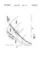
- the compressor mapis divided into three regions plus a small transition region as depicted in FIG. 1.
- values such as pressure ratio, rotational speed, or powercan be balanced in a predetermined way between compressors in the series network.
- This area, between Regions 1 and 2,is for smoothly transferring control between the different process variables used in these two regions.
- FIG. 1shows a compressor map with three boundaries between three regions plus a transition region.
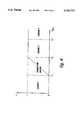
- FIG. 2shows a schematic diagram representing a series compressor network and control scheme.
- FIG. 3shows a block diagram of a control scheme for a series compressor network, inputting to a Load Sharing Controller.
- FIG. 4shows a plot of parameter x versus parameter S max .
- FIG. 5shows a block diagram of a Load Sharing Controller for turbocompressors operating in series.
- compressorsWhen compressors can all be operated “far from surge,” it is advisable to distribute the pressure ratio across all compressors in a predefined fashion. Running in such a manner as to maximize efficiency may be in order when compressors are driven by gas turbines.
- FIG. 2depicts such a network arrangement with two turbocompressors in series 20, both driven by steam turbines.
- Each compressorincorporates a separate control scheme comprising devices for monitoring process input signals, such as differential pressure across a flow measurement device 21 and across a compressor 28, pressure in suction 22, and pressure at discharge 23.
- This systemalso includes transmitters for recycle valve stem position 24, valve inlet temperature 25, suction temperature 27, discharge temperature 29, and rotational speed 26 data. These and other signals interact and are input as a balancing parameter to a Load Sharing Controller.
- a distance from the surge control linemust be defined beyond which there is no immediate threat of surge.
- performance of the compressorscan be manipulated to balance pressure ratio.
- a function of pressure ratio, ⁇ 2 (R c )is defined for control purposes. This function will bring the balancing parameter value in this region to less than unity and allow the marriage of Region 1 with Region 2 through the Transition Region.
- R cpressure ratio across the compressor, P d /P s
- the function ⁇ 1returns the value q s 2 , on the surge limit line, for the given value of the independent variable R c . Therefore, S s goes to unity on the surge limit line. It is less than unity to the safe (right) side of the surge limit line.
- Load balancing near the surge control lineentails manipulating the performance of each compressor such that all the compressors' ⁇ 's are related by proportioning constants-allowing them to go to zero simultaneously. Thus, no one compressor will recycle until all must recycle. This improves the energy efficiency of the process since recycling gas is wasteful from an energy consumption standpoint (but not from a safety standpoint). It also does not permit any compressor to be in much greater jeopardy of surging than any others-so they share the "danger load" as well.
- T 1temperature of the gas entering the valve
- FIG. 3A block diagram of the calculation of the balancing parameter S p * is shown in FIG. 3 where transmitter data from a high-pressure compressor (shown in FIG. 1) are computed to define S p * as an input to a Load Sharing Controller.
- a module 30calculates pressure ratio (R c ) which is assumed to be accurate for both the compressor and the recycle valve.
- a multiplier 34determines recycle relative mass flow (m v ) from the function of pressure ratio ⁇ 3 (R c )!, absolute pressure at discharge (p d ,HP) 23, and with data from both the recycle valve stem position transmitter ⁇ v (v)! 24 and the temperature transmitter (1/ ⁇ T 1 ,HP )25. Recycle relative mass flow is then added to a constant (1+m v )35.
- a divider 36yields a surge parameter (S s ) which is acted on by another module 37 that sums this value and a safety margin (b) to describe a surge parameter (S).
- a summing module 38Following a sequence of operations on the S parameter, a summing module 38 generates 1- ⁇ (1-S) that is multiplied by 1+m v , thereby defining the balancing parameter S p * 39 as an input to a Load Sharing Controller 40.
- xis the same for all compressors and is calculated using parameters corresponding to the compressor nearest its surge line.
- a balancing parameter, Bcan be defined as a function of x:
- Eq. (a)is used to define both the process variable and the set point for each load balancing controller.
- the value S p *for the specific compressor at hand, is used to calculate B.
- the set pointan average of all B's is calculated.
- FIG. 5details the use of Eq. (a) in a block diagram of the Load Sharing Controller (designated in FIG. 3) for a two-compressor network, wherein balancing parameters (S p ,1 * S p ,2 *) 50 are affected by a module 52 that generates a maximum S value (S max ) used in determining a parameter (x) 53. Additionally, pressure ratios (R c ,1, R c ,2) 51 along with the balancing parameters 50 and the x parameter 53, assist in computing process variables (PV 1 , PV 2 ) 54 and, in turn, a set point (SP) 55. Another module 56 then calculates error (.di-elect cons. 1 , .di-elect cons. 2 ) used to derive output signals 57, 58 which are subsequently transmitted to specific compressor speed governors 59, 60.
- error.di-elect cons. 1 , .di-elect cons. 2
- Balancing during recyclecan be accomplished without computing the relative mass flows through the recycle valves. For example, it is possible to balance using only the combination of a function of pressure ratio, ⁇ 3 (R c ,v), and a function of the recycle valve position, ⁇ v (v); or even using ⁇ v (v) by itself. Moreover, compensation can be made for temperature differences. These methods can also be applied to compressors in parallel.
Landscapes
- Engineering & Computer Science (AREA)
- Mechanical Engineering (AREA)
- General Engineering & Computer Science (AREA)
- Control Of Positive-Displacement Air Blowers (AREA)
- Structures Of Non-Positive Displacement Pumps (AREA)
- Control Of Positive-Displacement Pumps (AREA)
- Control Of Non-Positive-Displacement Pumps (AREA)
- Control Of Multiple Motors (AREA)
- Separation By Low-Temperature Treatments (AREA)
Abstract
Description
S.sub.p *= 1-β(1-S)! 1+m.sub.v !
B=(1-x)ƒ.sub.2 (R.sub.c)+x 1-β(1-S)! 1+m.sub.v !=β.sub.2 +β.sub.1 S.sub.p *tm (a)
β.sub.1 =x and β.sub.2 =(1-x)ƒ.sub.2 (R.sub.c)
Claims (60)
Priority Applications (14)
| Application Number | Priority Date | Filing Date | Title |
|---|---|---|---|
| US08/546,114US5743715A (en) | 1995-10-20 | 1995-10-20 | Method and apparatus for load balancing among multiple compressors |
| CA002184130ACA2184130A1 (en) | 1995-10-20 | 1996-08-26 | Method and apparatus for load balancing among multiple compressors |
| NO963591ANO963591L (en) | 1995-10-20 | 1996-08-28 | Method and device for load balancing among several compressors |
| SK1329-96ASK132996A3 (en) | 1995-10-20 | 1996-10-16 | Load sharing method between multiple compressors and apparatus for carrying out this method |
| CZ963046ACZ304696A3 (en) | 1995-10-20 | 1996-10-17 | Method and apparatus for equalizing load among multiple compressors |
| HR08/546,114AHRP960476A2 (en) | 1995-10-20 | 1996-10-18 | Method and apparatus for load balancing among multiple compressors |
| AT96420313TATE211222T1 (en) | 1995-10-20 | 1996-10-18 | METHOD AND DEVICE FOR BALANCING THE LOAD BETWEEN SEVERAL COMPRESSORS |
| HU9602898AHUP9602898A3 (en) | 1995-10-20 | 1996-10-18 | Method and apparatus for controlling compressors |
| DE69618140TDE69618140T2 (en) | 1995-10-20 | 1996-10-18 | Method and device for load balancing between several compressors |
| BG100922ABG100922A (en) | 1995-10-20 | 1996-10-18 | METHOD AND DEVICE FOR BALANCE OF LOAD INTERMEDIATE COMPRESSORS |
| EP96420313AEP0769624B1 (en) | 1995-10-20 | 1996-10-18 | Method and apparatus for load balancing among multiple compressors |
| EA199600085AEA000267B1 (en) | 1995-10-20 | 1996-10-18 | Method and apparatus for load balancing among multiple compressors |
| UA96103950AUA41988C2 (en) | 1995-10-20 | 1996-10-18 | Method for control of gas compression system (versions) and appliance for its implementation (versions) |
| PL96316607APL316607A1 (en) | 1995-10-20 | 1996-10-21 | Method of controlling operation of a bank of compressors and apparatus therefor |
Applications Claiming Priority (1)
| Application Number | Priority Date | Filing Date | Title |
|---|---|---|---|
| US08/546,114US5743715A (en) | 1995-10-20 | 1995-10-20 | Method and apparatus for load balancing among multiple compressors |
Publications (1)
| Publication Number | Publication Date |
|---|---|
| US5743715Atrue US5743715A (en) | 1998-04-28 |
Family
ID=24178932
Family Applications (1)
| Application Number | Title | Priority Date | Filing Date |
|---|---|---|---|
| US08/546,114Expired - LifetimeUS5743715A (en) | 1995-10-20 | 1995-10-20 | Method and apparatus for load balancing among multiple compressors |
Country Status (14)
| Country | Link |
|---|---|
| US (1) | US5743715A (en) |
| EP (1) | EP0769624B1 (en) |
| AT (1) | ATE211222T1 (en) |
| BG (1) | BG100922A (en) |
| CA (1) | CA2184130A1 (en) |
| CZ (1) | CZ304696A3 (en) |
| DE (1) | DE69618140T2 (en) |
| EA (1) | EA000267B1 (en) |
| HR (1) | HRP960476A2 (en) |
| HU (1) | HUP9602898A3 (en) |
| NO (1) | NO963591L (en) |
| PL (1) | PL316607A1 (en) |
| SK (1) | SK132996A3 (en) |
| UA (1) | UA41988C2 (en) |
Cited By (53)
| Publication number | Priority date | Publication date | Assignee | Title |
|---|---|---|---|---|
| US5845509A (en)* | 1997-09-26 | 1998-12-08 | Shaw; David N. | Variable speed parallel centrifugal compressors for HVAC and refrigeration systems |
| US5908462A (en)* | 1996-12-06 | 1999-06-01 | Compressor Controls Corporation | Method and apparatus for antisurge control of turbocompressors having surge limit lines with small slopes |
| US6185946B1 (en) | 1999-05-07 | 2001-02-13 | Thomas B. Hartman | System for sequencing chillers in a loop cooling plant and other systems that employ all variable-speed units |
| US6241463B1 (en)* | 1997-06-23 | 2001-06-05 | Babcock-Bsh Gmbh | Method for determining the operating level of a fan and fan |
| DE10003869A1 (en)* | 2000-01-28 | 2001-08-16 | Aerzener Maschf Gmbh | Compressing fluid conveying mediums using at least two compressor units so that the outlet of the respective series connected compressor unit is in communication |
| US6503048B1 (en)* | 2001-08-27 | 2003-01-07 | Compressor Controls Corporation | Method and apparatus for estimating flow in compressors with sidestreams |
| US6602057B2 (en) | 2001-10-01 | 2003-08-05 | Dresser-Rand Company | Management and optimization of load sharing between multiple compressor trains for controlling a main process gas variable |
| US20030161731A1 (en)* | 2002-02-28 | 2003-08-28 | Wilfried Blotenberg | Process for controlling a plurality of turbo engines in parallel or tandem operation |
| US6625573B2 (en)* | 2000-06-20 | 2003-09-23 | Petr A. Petrosov | Method and apparatus of molecular weight determination for gases flowing through the compressor |
| US20040151576A1 (en)* | 2003-01-31 | 2004-08-05 | Wilfried Blotenberg | Process for the reliable operation of turbocompressors with surge limit control and surge limit control valve |
| US20040265133A1 (en)* | 2001-10-16 | 2004-12-30 | Siemens Aktiengesellschaft | Method for optimizing the operation of a plurality of compressor assemblies of a natural-gas compression station |
| US7094019B1 (en)* | 2004-05-17 | 2006-08-22 | Continuous Control Solutions, Inc. | System and method of surge limit control for turbo compressors |
| US7155367B1 (en) | 2005-01-25 | 2006-12-26 | Continuous Control Solutions, Inc. | Method for evaluating relative efficiency of equipment |
| US20070065300A1 (en)* | 2005-09-19 | 2007-03-22 | Ingersoll-Rand Company | Multi-stage compression system including variable speed motors |
| US20070068182A1 (en)* | 2003-11-21 | 2007-03-29 | Uwe Folchert | Method for controlling a compressor for conveying a pressure medium in a level adjustment system of a motor vehicle |
| US20080201718A1 (en)* | 2007-02-16 | 2008-08-21 | Ofir Zohar | Method, an apparatus and a system for managing a distributed compression system |
| US20090232663A1 (en)* | 2008-03-13 | 2009-09-17 | Saul Mirsky | Compressor-Expander Set Critical Speed Avoidance |
| US20090252617A1 (en)* | 2004-12-14 | 2009-10-08 | Siemens Aktiengesellschaft | Method for operation of a compressor supplied by a power converter |
| US20100198409A1 (en)* | 2009-02-02 | 2010-08-05 | Hartman Thomas B | Sequencing of variable speed compressors in a chilled liquid cooling system for improved energy efficiency |
| US20110027066A1 (en)* | 2008-03-28 | 2011-02-03 | Mitsubishi Heavy Industries, Ltd. | Method of controlling turbine equipment and turbine equipment |
| US20110112797A1 (en)* | 2008-04-28 | 2011-05-12 | Nuehse Andreas | Efficiency monitoring of a compressor |
| US20110126584A1 (en)* | 2008-07-29 | 2011-06-02 | Frederick Jan Van Dijk | Method and apparatus for treating a hydrocarbon stream and method of cooling a hydrocarbon stream |
| US20110130883A1 (en)* | 2008-07-29 | 2011-06-02 | Frederick Jan Van Dijk | Method and apparatus for controlling a compressor and method of cooling a hydrocarbon stream |
| CN102392812A (en)* | 2011-06-10 | 2012-03-28 | 辽宁华兴森威科技发展有限公司 | Surge control system of compressor unit |
| US20120121440A1 (en)* | 2007-08-21 | 2012-05-17 | Geoffrey George Powell | Compressors control |
| US20120230840A1 (en)* | 2009-11-12 | 2012-09-13 | Rolls-Royce Plc | Gas compression |
| US8323000B2 (en) | 2008-06-23 | 2012-12-04 | Compressor Controls Corp. | Compressor-driver power limiting in consideration of antisurge control |
| US20120328410A1 (en)* | 2011-06-27 | 2012-12-27 | Energy Control Technologies, Inc. | Surge estimator |
| US20130108473A1 (en)* | 2011-11-02 | 2013-05-02 | Abb Oy | Method and controller for operating a pump system |
| US20140094105A1 (en)* | 2011-06-16 | 2014-04-03 | Michael Lundh | Method And System For Fluid Flow Control In A Fluid Network System |
| US8925197B2 (en) | 2012-05-29 | 2015-01-06 | Praxair Technology, Inc. | Compressor thrust bearing surge protection |
| WO2015077282A1 (en)* | 2013-11-25 | 2015-05-28 | Woodward, Inc. | Load sharing control for compressors in series |
| WO2015138172A1 (en)* | 2014-03-11 | 2015-09-17 | Borgwarner Inc. | Method for identifying the surge limit of a compressor |
| CN105697404A (en)* | 2014-12-11 | 2016-06-22 | 福特环球技术公司 | Methods and systems for controlling compressor surge |
| US9506474B2 (en)* | 2014-12-08 | 2016-11-29 | Ford Global Technologies, Llc | Methods and systems for real-time compressor surge line adaptation |
| US20170127262A1 (en)* | 2015-11-04 | 2017-05-04 | Abb Technology Oy | Indicating a drive status in communications |
| US9677782B1 (en)* | 2008-10-29 | 2017-06-13 | Climatecraft, Inc. | Fan system comprising fan array with surge control |
| US9879688B2 (en) | 2008-03-13 | 2018-01-30 | Compressor Controls Corporation | Enhanced turbocompressor startup |
| US20180135637A1 (en)* | 2010-05-11 | 2018-05-17 | Energy Control Technologies, Inc. | Method of anti-surge protection for a dynamic compressor using a surge parameter |
| US10254719B2 (en) | 2015-09-18 | 2019-04-09 | Statistics & Control, Inc. | Method and apparatus for surge prevention control of multistage compressor having one surge valve and at least one flow measuring device |
| US10316740B2 (en)* | 2017-02-15 | 2019-06-11 | Borgwarner Inc. | Systems including an electrically assisted turbocharger and methods of using the same |
| US10436488B2 (en) | 2002-12-09 | 2019-10-08 | Hudson Technologies Inc. | Method and apparatus for optimizing refrigeration systems |
| CN110617233A (en)* | 2018-06-19 | 2019-12-27 | 中国石油集团西部管道有限责任公司 | Load distribution control system of natural gas long-distance pipeline compressor unit |
| CN111656018A (en)* | 2018-02-27 | 2020-09-11 | 依必安派特穆尔芬根有限两合公司 | Operating point determination |
| CN112610522A (en)* | 2020-12-31 | 2021-04-06 | 浙江中控技术股份有限公司 | Control method of series compressor unit and related equipment |
| US11268524B2 (en)* | 2017-04-27 | 2022-03-08 | Cryostar Sas | Method for controlling a plural stage compressor |
| US11408418B2 (en)* | 2019-08-13 | 2022-08-09 | Rockwell Automation Technologies, Inc. | Industrial control system for distributed compressors |
| US20220397119A1 (en)* | 2021-06-14 | 2022-12-15 | Air Products And Chemicals, Inc. | Method and apparatus for compressing a gas feed with a variable flow rate |
| US11656612B2 (en) | 2021-07-19 | 2023-05-23 | Air Products And Chemicals, Inc. | Method and apparatus for managing industrial gas production |
| CN119962237A (en)* | 2025-02-06 | 2025-05-09 | 哈尔滨汽轮机厂有限责任公司 | Simulation data acquisition method for three-stage series compressor |
| US12305651B2 (en) | 2021-06-14 | 2025-05-20 | Air Products And Chemicals, Inc. | Process and apparatus for operating a compression system |
| US12314065B2 (en) | 2022-08-12 | 2025-05-27 | Air Products And Chemicals, Inc. | Method and system for controlling production and storage of industrial gases |
| US12442369B2 (en) | 2022-08-12 | 2025-10-14 | Air Products And Chemicals, Inc. | Method and system for load control of reciprocating compressors |
Families Citing this family (12)
| Publication number | Priority date | Publication date | Assignee | Title |
|---|---|---|---|---|
| DE19812159A1 (en)* | 1998-03-20 | 1999-09-23 | Ruhrgas Ag | Regulating flow of natural gas, using turbocompressor in pipe network with bypass line with regulating valve |
| DE102005006410A1 (en) | 2005-02-11 | 2006-08-17 | Siemens Ag | Method for optimizing the operation of several compressor units and apparatus for this purpose |
| DE102008058799B4 (en) | 2008-11-24 | 2012-04-26 | Siemens Aktiengesellschaft | Method for operating a multi-stage compressor |
| US20110293537A1 (en)* | 2008-11-24 | 2011-12-01 | Giovanni Nicolao Berta | formulations with anti-neoplastic activity |
| GB2480270A (en)* | 2010-05-11 | 2011-11-16 | Rolls Royce Plc | Waste gas compressor train |
| JP5871157B2 (en)* | 2011-10-03 | 2016-03-01 | 株式会社Ihi | Method for preventing surging of centrifugal compression equipment |
| RU2542631C1 (en)* | 2014-02-27 | 2015-02-20 | Открытое акционерное общество "Уфимское моторостроительное производственное объединение" ОАО "УМПО" | System to control dual-shaft gas turbine compressor stator position |
| JP6501380B2 (en)* | 2014-07-01 | 2019-04-17 | 三菱重工コンプレッサ株式会社 | Multistage compressor system, control device, abnormality determination method and program |
| EP3147511A1 (en)* | 2015-09-22 | 2017-03-29 | Siemens Aktiengesellschaft | Method for surge control, turbo compressor |
| WO2019179997A1 (en) | 2018-03-20 | 2019-09-26 | Enersize Oy | A method for designing, gauging and optimizing a multilpe compressor system with respect to energy efficiency |
| WO2019180003A1 (en) | 2018-03-20 | 2019-09-26 | Enersize Oy | A method for analyzing, monitoring, optimizing and/or comparing energy efficiency in a multiple compressor system |
| CN113464845B (en)* | 2021-07-13 | 2022-08-30 | 清华大学 | Gas circuit assembly and surge suppression system |
Citations (19)
| Publication number | Priority date | Publication date | Assignee | Title |
|---|---|---|---|---|
| US3979655A (en)* | 1975-03-31 | 1976-09-07 | Compressor Controls Corporation | Control system for controlling a dynamic compressor |
| US3994623A (en)* | 1975-02-11 | 1976-11-30 | Compressor Controls Corporation | Method and apparatus for controlling a dynamic compressor |
| US4046490A (en)* | 1975-12-01 | 1977-09-06 | Compressor Controls Corporation | Method and apparatus for antisurge protection of a dynamic compressor |
| US4203701A (en)* | 1978-08-22 | 1980-05-20 | Simmonds Precision Products, Inc. | Surge control for centrifugal compressors |
| USRE30329E (en)* | 1975-12-01 | 1980-07-08 | Compressor Controls Corp. | Method and apparatus for antisurge protection of a dynamic compressor |
| US4464720A (en)* | 1982-02-12 | 1984-08-07 | The Babcock & Wilcox Company | Centrifugal compressor surge control system |
| US4494006A (en)* | 1982-09-15 | 1985-01-15 | Compressor Controls Corporation | Method and apparatus for controlling a multicompressor station |
| US4526513A (en)* | 1980-07-18 | 1985-07-02 | Acco Industries Inc. | Method and apparatus for control of pipeline compressors |
| US4640665A (en)* | 1982-09-15 | 1987-02-03 | Compressor Controls Corp. | Method for controlling a multicompressor station |
| US4656589A (en)* | 1981-02-14 | 1987-04-07 | M.A.N.Maschinenfabrik Augsburg-Nurnberg | Method and apparatus for operating turbo compressor using analog and digital control schemes |
| US4825380A (en)* | 1987-05-19 | 1989-04-25 | Phillips Petroleum Company | Molecular weight determination for constraint control of a compressor |
| US4831535A (en)* | 1985-12-18 | 1989-05-16 | Man Gutehoffnungshuette Gmbh | Method of controlling the surge limit of turbocompressors |
| US4861233A (en)* | 1983-10-07 | 1989-08-29 | The Babcock & Wilcox Company | Compressor surge control system |
| US4949276A (en)* | 1988-10-26 | 1990-08-14 | Compressor Controls Corp. | Method and apparatus for preventing surge in a dynamic compressor |
| US4971516A (en)* | 1988-05-04 | 1990-11-20 | Exxon Research & Engineering Company | Surge control in compressors |
| US5195875A (en)* | 1991-12-05 | 1993-03-23 | Dresser-Rand Company | Antisurge control system for compressors |
| US5306116A (en)* | 1992-04-10 | 1994-04-26 | Ingersoll-Rand Company | Surge control and recovery for a centrifugal compressor |
| US5347467A (en)* | 1992-06-22 | 1994-09-13 | Compressor Controls Corporation | Load sharing method and apparatus for controlling a main gas parameter of a compressor station with multiple dynamic compressors |
| US5508943A (en)* | 1994-04-07 | 1996-04-16 | Compressor Controls Corporation | Method and apparatus for measuring the distance of a turbocompressor's operating point to the surge limit interface |
Family Cites Families (10)
| Publication number | Priority date | Publication date | Assignee | Title |
|---|---|---|---|---|
| US3767318A (en)* | 1971-05-10 | 1973-10-23 | Mitsui Shipbuilding Eng | Method of controlling multi-casing variable speed compressors |
| SU590488A1 (en)* | 1972-07-28 | 1978-01-30 | Предприятие П/Я В-2803 | Method of counter-surge protection of multi-section centrifugal compressor |
| SU524928A1 (en)* | 1973-01-23 | 1976-08-15 | Предприятие П/Я А-3513 | Pressure control system in the output manifold of the compressor group |
| DE2614176A1 (en)* | 1976-04-02 | 1977-10-13 | Gutehoffnungshuette Sterkrade | MULTI-STAGE COMPRESSOR |
| JPS608497A (en)* | 1983-06-29 | 1985-01-17 | Hitachi Ltd | Capacity regulation method and system for multi-stage compressor |
| US4560319A (en)* | 1983-08-01 | 1985-12-24 | MAN Maschinenfabrik Unternehmensbereich GHH Sterkrade | Method and apparatus for controlling at least two parallel-connected turbocompressors |
| SU1701989A1 (en)* | 1988-11-05 | 1991-12-30 | Киевский институт автоматики им.ХХУ съезда КПСС | Method of control of compressor station |
| DE4122631A1 (en)* | 1991-07-09 | 1993-01-14 | Linde Ag | Regulating operation of compressor - adjusting RPM or setting guide vanes according to desired value delivered by process regulator |
| IT1255836B (en)* | 1991-10-01 | 1995-11-17 | PROCEDURE FOR THE SURVEILLANCE OF THE PUMPING LIMIT OF MULTI-STAGE TURBOCHARGERS AND INTERMEDIATE REFRIGERATION | |
| US5343384A (en)* | 1992-10-13 | 1994-08-30 | Ingersoll-Rand Company | Method and apparatus for controlling a system of compressors to achieve load sharing |
- 1995
- 1995-10-20USUS08/546,114patent/US5743715A/ennot_activeExpired - Lifetime
- 1996
- 1996-08-26CACA002184130Apatent/CA2184130A1/ennot_activeAbandoned
- 1996-08-28NONO963591Apatent/NO963591L/ennot_activeApplication Discontinuation
- 1996-10-16SKSK1329-96Apatent/SK132996A3/enunknown
- 1996-10-17CZCZ963046Apatent/CZ304696A3/enunknown
- 1996-10-18UAUA96103950Apatent/UA41988C2/enunknown
- 1996-10-18ATAT96420313Tpatent/ATE211222T1/ennot_activeIP Right Cessation
- 1996-10-18EAEA199600085Apatent/EA000267B1/ennot_activeIP Right Cessation
- 1996-10-18DEDE69618140Tpatent/DE69618140T2/ennot_activeExpired - Lifetime
- 1996-10-18HUHU9602898Apatent/HUP9602898A3/enunknown
- 1996-10-18EPEP96420313Apatent/EP0769624B1/ennot_activeExpired - Lifetime
- 1996-10-18BGBG100922Apatent/BG100922A/enunknown
- 1996-10-18HRHR08/546,114Apatent/HRP960476A2/ennot_activeApplication Discontinuation
- 1996-10-21PLPL96316607Apatent/PL316607A1/enunknown
Patent Citations (19)
| Publication number | Priority date | Publication date | Assignee | Title |
|---|---|---|---|---|
| US3994623A (en)* | 1975-02-11 | 1976-11-30 | Compressor Controls Corporation | Method and apparatus for controlling a dynamic compressor |
| US3979655A (en)* | 1975-03-31 | 1976-09-07 | Compressor Controls Corporation | Control system for controlling a dynamic compressor |
| US4046490A (en)* | 1975-12-01 | 1977-09-06 | Compressor Controls Corporation | Method and apparatus for antisurge protection of a dynamic compressor |
| USRE30329E (en)* | 1975-12-01 | 1980-07-08 | Compressor Controls Corp. | Method and apparatus for antisurge protection of a dynamic compressor |
| US4203701A (en)* | 1978-08-22 | 1980-05-20 | Simmonds Precision Products, Inc. | Surge control for centrifugal compressors |
| US4526513A (en)* | 1980-07-18 | 1985-07-02 | Acco Industries Inc. | Method and apparatus for control of pipeline compressors |
| US4656589A (en)* | 1981-02-14 | 1987-04-07 | M.A.N.Maschinenfabrik Augsburg-Nurnberg | Method and apparatus for operating turbo compressor using analog and digital control schemes |
| US4464720A (en)* | 1982-02-12 | 1984-08-07 | The Babcock & Wilcox Company | Centrifugal compressor surge control system |
| US4640665A (en)* | 1982-09-15 | 1987-02-03 | Compressor Controls Corp. | Method for controlling a multicompressor station |
| US4494006A (en)* | 1982-09-15 | 1985-01-15 | Compressor Controls Corporation | Method and apparatus for controlling a multicompressor station |
| US4861233A (en)* | 1983-10-07 | 1989-08-29 | The Babcock & Wilcox Company | Compressor surge control system |
| US4831535A (en)* | 1985-12-18 | 1989-05-16 | Man Gutehoffnungshuette Gmbh | Method of controlling the surge limit of turbocompressors |
| US4825380A (en)* | 1987-05-19 | 1989-04-25 | Phillips Petroleum Company | Molecular weight determination for constraint control of a compressor |
| US4971516A (en)* | 1988-05-04 | 1990-11-20 | Exxon Research & Engineering Company | Surge control in compressors |
| US4949276A (en)* | 1988-10-26 | 1990-08-14 | Compressor Controls Corp. | Method and apparatus for preventing surge in a dynamic compressor |
| US5195875A (en)* | 1991-12-05 | 1993-03-23 | Dresser-Rand Company | Antisurge control system for compressors |
| US5306116A (en)* | 1992-04-10 | 1994-04-26 | Ingersoll-Rand Company | Surge control and recovery for a centrifugal compressor |
| US5347467A (en)* | 1992-06-22 | 1994-09-13 | Compressor Controls Corporation | Load sharing method and apparatus for controlling a main gas parameter of a compressor station with multiple dynamic compressors |
| US5508943A (en)* | 1994-04-07 | 1996-04-16 | Compressor Controls Corporation | Method and apparatus for measuring the distance of a turbocompressor's operating point to the surge limit interface |
Non-Patent Citations (2)
| Title |
|---|
| Manual 149 pages from Compressor Controls Corporation printed 1987 1995 and entitled Series 3 Plus Performance Controller for Centrifugal and Axial Compressors Publication IM302 (4.0) Software Revision: 953 002 Jul., 1995.* |
| Manual--149-pages from Compressor Controls Corporation printed 1987-1995 and entitled Series 3 Plus Performance Controller for Centrifugal and Axial Compressors--Publication IM302 (4.0) Software Revision: 953-002 Jul., 1995. |
Cited By (91)
| Publication number | Priority date | Publication date | Assignee | Title |
|---|---|---|---|---|
| US5908462A (en)* | 1996-12-06 | 1999-06-01 | Compressor Controls Corporation | Method and apparatus for antisurge control of turbocompressors having surge limit lines with small slopes |
| US6241463B1 (en)* | 1997-06-23 | 2001-06-05 | Babcock-Bsh Gmbh | Method for determining the operating level of a fan and fan |
| US5845509A (en)* | 1997-09-26 | 1998-12-08 | Shaw; David N. | Variable speed parallel centrifugal compressors for HVAC and refrigeration systems |
| US6185946B1 (en) | 1999-05-07 | 2001-02-13 | Thomas B. Hartman | System for sequencing chillers in a loop cooling plant and other systems that employ all variable-speed units |
| DE10003869C5 (en)* | 2000-01-28 | 2007-11-08 | Aerzener Maschinenfabrik Gmbh | Method for compressing fluid fluids |
| DE10003869C2 (en)* | 2000-01-28 | 2003-07-17 | Aerzener Maschf Gmbh | Process for compressing fluid media |
| DE10003869A1 (en)* | 2000-01-28 | 2001-08-16 | Aerzener Maschf Gmbh | Compressing fluid conveying mediums using at least two compressor units so that the outlet of the respective series connected compressor unit is in communication |
| US6625573B2 (en)* | 2000-06-20 | 2003-09-23 | Petr A. Petrosov | Method and apparatus of molecular weight determination for gases flowing through the compressor |
| US6503048B1 (en)* | 2001-08-27 | 2003-01-07 | Compressor Controls Corporation | Method and apparatus for estimating flow in compressors with sidestreams |
| US6602057B2 (en) | 2001-10-01 | 2003-08-05 | Dresser-Rand Company | Management and optimization of load sharing between multiple compressor trains for controlling a main process gas variable |
| WO2003028841A3 (en)* | 2001-10-01 | 2003-11-06 | Dresser Rand Co | Optimization of multiple compressor trains |
| US7600981B2 (en)* | 2001-10-16 | 2009-10-13 | Dieter Lau | Method for optimizing the operation of a plurality of compressor assemblies of a natural-gas compression station |
| US20040265133A1 (en)* | 2001-10-16 | 2004-12-30 | Siemens Aktiengesellschaft | Method for optimizing the operation of a plurality of compressor assemblies of a natural-gas compression station |
| US20030161731A1 (en)* | 2002-02-28 | 2003-08-28 | Wilfried Blotenberg | Process for controlling a plurality of turbo engines in parallel or tandem operation |
| US10436488B2 (en) | 2002-12-09 | 2019-10-08 | Hudson Technologies Inc. | Method and apparatus for optimizing refrigeration systems |
| US7025558B2 (en)* | 2003-01-31 | 2006-04-11 | Man Turbo Ag | Process for the reliable operation of turbocompressors with surge limit control and surge limit control valve |
| US20040151576A1 (en)* | 2003-01-31 | 2004-08-05 | Wilfried Blotenberg | Process for the reliable operation of turbocompressors with surge limit control and surge limit control valve |
| US20070068182A1 (en)* | 2003-11-21 | 2007-03-29 | Uwe Folchert | Method for controlling a compressor for conveying a pressure medium in a level adjustment system of a motor vehicle |
| US7094019B1 (en)* | 2004-05-17 | 2006-08-22 | Continuous Control Solutions, Inc. | System and method of surge limit control for turbo compressors |
| US8070456B2 (en)* | 2004-12-14 | 2011-12-06 | Siemens Aktiengesellschaft | Method for preventing power surge in a compressor supplied by a power converter by direct torque control |
| US20090252617A1 (en)* | 2004-12-14 | 2009-10-08 | Siemens Aktiengesellschaft | Method for operation of a compressor supplied by a power converter |
| US7155367B1 (en) | 2005-01-25 | 2006-12-26 | Continuous Control Solutions, Inc. | Method for evaluating relative efficiency of equipment |
| US20070065300A1 (en)* | 2005-09-19 | 2007-03-22 | Ingersoll-Rand Company | Multi-stage compression system including variable speed motors |
| US8776052B2 (en)* | 2007-02-16 | 2014-07-08 | International Business Machines Corporation | Method, an apparatus and a system for managing a distributed compression system |
| US20080201718A1 (en)* | 2007-02-16 | 2008-08-21 | Ofir Zohar | Method, an apparatus and a system for managing a distributed compression system |
| US9086070B2 (en)* | 2007-08-21 | 2015-07-21 | Gardner Denver Deutschland Gmbh | Compressors control |
| US20120121440A1 (en)* | 2007-08-21 | 2012-05-17 | Geoffrey George Powell | Compressors control |
| US20090232663A1 (en)* | 2008-03-13 | 2009-09-17 | Saul Mirsky | Compressor-Expander Set Critical Speed Avoidance |
| US20180149163A1 (en)* | 2008-03-13 | 2018-05-31 | Compressor Controls Corporation | Enhanced turbocompressor starup |
| US9879688B2 (en) | 2008-03-13 | 2018-01-30 | Compressor Controls Corporation | Enhanced turbocompressor startup |
| US10935036B2 (en)* | 2008-03-13 | 2021-03-02 | Compressor Controls Corporation | Enhanced turbocompressor startup |
| EP2124004A2 (en) | 2008-03-13 | 2009-11-25 | Compressor Controls Corporation | Compressor-expander set critical speed avoidance |
| US8360744B2 (en) | 2008-03-13 | 2013-01-29 | Compressor Controls Corporation | Compressor-expander set critical speed avoidance |
| US20130094974A1 (en)* | 2008-03-13 | 2013-04-18 | Compressor Controls Corporation | Compressor-Expander Set Critical Speed Avoidance |
| US8540498B2 (en)* | 2008-03-13 | 2013-09-24 | Compressor Controls Corp. | Compressor-expander set critical speed avoidance |
| US20130129528A1 (en)* | 2008-03-13 | 2013-05-23 | Compressor Controls Corporation | Compressor-Expander Set Critical Speed Avoidance |
| US20110027066A1 (en)* | 2008-03-28 | 2011-02-03 | Mitsubishi Heavy Industries, Ltd. | Method of controlling turbine equipment and turbine equipment |
| US9243566B2 (en)* | 2008-03-28 | 2016-01-26 | Mitsubishi Heavy Industries, Ltd. | Method of controlling turbine equipment and turbine equipment |
| US20110112797A1 (en)* | 2008-04-28 | 2011-05-12 | Nuehse Andreas | Efficiency monitoring of a compressor |
| US8323000B2 (en) | 2008-06-23 | 2012-12-04 | Compressor Controls Corp. | Compressor-driver power limiting in consideration of antisurge control |
| WO2010012559A3 (en)* | 2008-07-29 | 2014-10-09 | Shell Internationale Research Maatschappij B.V. | Method and apparatus for controlling a compressor and method of cooling a hydrocarbon stream |
| US8532830B2 (en) | 2008-07-29 | 2013-09-10 | Shell Oil Company | Method and apparatus for controlling a compressor and method of cooling a hydrocarbon stream |
| US20110126584A1 (en)* | 2008-07-29 | 2011-06-02 | Frederick Jan Van Dijk | Method and apparatus for treating a hydrocarbon stream and method of cooling a hydrocarbon stream |
| US20110130883A1 (en)* | 2008-07-29 | 2011-06-02 | Frederick Jan Van Dijk | Method and apparatus for controlling a compressor and method of cooling a hydrocarbon stream |
| US9677782B1 (en)* | 2008-10-29 | 2017-06-13 | Climatecraft, Inc. | Fan system comprising fan array with surge control |
| US20100198409A1 (en)* | 2009-02-02 | 2010-08-05 | Hartman Thomas B | Sequencing of variable speed compressors in a chilled liquid cooling system for improved energy efficiency |
| US8291720B2 (en) | 2009-02-02 | 2012-10-23 | Optimum Energy, Llc | Sequencing of variable speed compressors in a chilled liquid cooling system for improved energy efficiency |
| US9022747B2 (en)* | 2009-11-12 | 2015-05-05 | Rolls-Royce Plc | Gas compression |
| US20120230840A1 (en)* | 2009-11-12 | 2012-09-13 | Rolls-Royce Plc | Gas compression |
| US10900492B2 (en)* | 2010-05-11 | 2021-01-26 | Energy Control Technologies, Inc. | Method of anti-surge protection for a dynamic compressor using a surge parameter |
| US20180135637A1 (en)* | 2010-05-11 | 2018-05-17 | Energy Control Technologies, Inc. | Method of anti-surge protection for a dynamic compressor using a surge parameter |
| CN102392812A (en)* | 2011-06-10 | 2012-03-28 | 辽宁华兴森威科技发展有限公司 | Surge control system of compressor unit |
| CN102392812B (en)* | 2011-06-10 | 2015-09-30 | 辽宁华兴森威科技发展有限公司 | Surge control system of compressor unit |
| US9382798B2 (en)* | 2011-06-16 | 2016-07-05 | Abb Research Ltd. | Method and system for fluid flow control in a fluid network system |
| US20140094105A1 (en)* | 2011-06-16 | 2014-04-03 | Michael Lundh | Method And System For Fluid Flow Control In A Fluid Network System |
| US20120328410A1 (en)* | 2011-06-27 | 2012-12-27 | Energy Control Technologies, Inc. | Surge estimator |
| US10436208B2 (en)* | 2011-06-27 | 2019-10-08 | Energy Control Technologies, Inc. | Surge estimator |
| US20130108473A1 (en)* | 2011-11-02 | 2013-05-02 | Abb Oy | Method and controller for operating a pump system |
| US9091259B2 (en)* | 2011-11-02 | 2015-07-28 | Abb Technology Oy | Method and controller for operating a pump system |
| US8925197B2 (en) | 2012-05-29 | 2015-01-06 | Praxair Technology, Inc. | Compressor thrust bearing surge protection |
| US9695834B2 (en) | 2013-11-25 | 2017-07-04 | Woodward, Inc. | Load sharing control for compressors in series |
| US10400776B2 (en)* | 2013-11-25 | 2019-09-03 | Woodward, Inc. | Load sharing control for compressors in series |
| CN105917122B (en)* | 2013-11-25 | 2017-12-15 | 伍德沃德有限公司 | Load for compressors in series distributes control |
| WO2015077282A1 (en)* | 2013-11-25 | 2015-05-28 | Woodward, Inc. | Load sharing control for compressors in series |
| CN105917122A (en)* | 2013-11-25 | 2016-08-31 | 伍德沃德有限公司 | Load sharing control for compressors in series |
| WO2015138172A1 (en)* | 2014-03-11 | 2015-09-17 | Borgwarner Inc. | Method for identifying the surge limit of a compressor |
| CN106062375A (en)* | 2014-03-11 | 2016-10-26 | 博格华纳公司 | Method for identifying the surge limit of a compressor |
| US9506474B2 (en)* | 2014-12-08 | 2016-11-29 | Ford Global Technologies, Llc | Methods and systems for real-time compressor surge line adaptation |
| CN105697404A (en)* | 2014-12-11 | 2016-06-22 | 福特环球技术公司 | Methods and systems for controlling compressor surge |
| CN105697404B (en)* | 2014-12-11 | 2019-12-20 | 福特环球技术公司 | Method and system for controlling compressor surge |
| US10254719B2 (en) | 2015-09-18 | 2019-04-09 | Statistics & Control, Inc. | Method and apparatus for surge prevention control of multistage compressor having one surge valve and at least one flow measuring device |
| US9826387B2 (en)* | 2015-11-04 | 2017-11-21 | Abb Technology Oy | Indicating a drive status in communications |
| US20170127262A1 (en)* | 2015-11-04 | 2017-05-04 | Abb Technology Oy | Indicating a drive status in communications |
| US10316740B2 (en)* | 2017-02-15 | 2019-06-11 | Borgwarner Inc. | Systems including an electrically assisted turbocharger and methods of using the same |
| US11268524B2 (en)* | 2017-04-27 | 2022-03-08 | Cryostar Sas | Method for controlling a plural stage compressor |
| CN111656018A (en)* | 2018-02-27 | 2020-09-11 | 依必安派特穆尔芬根有限两合公司 | Operating point determination |
| US11846292B2 (en) | 2018-02-27 | 2023-12-19 | Ebm-Papst Mulfingen Gmbh & Co. Kg | Method for determining the operating point |
| CN111656018B (en)* | 2018-02-27 | 2022-03-29 | 依必安派特穆尔芬根有限两合公司 | Method for determining the operating point of a ventilator |
| CN110617233A (en)* | 2018-06-19 | 2019-12-27 | 中国石油集团西部管道有限责任公司 | Load distribution control system of natural gas long-distance pipeline compressor unit |
| CN110617233B (en)* | 2018-06-19 | 2021-03-30 | 中国石油集团西部管道有限责任公司 | Load Distribution Control System for Compressor Units in Long-distance Natural Gas Transmission Pipelines |
| US11408418B2 (en)* | 2019-08-13 | 2022-08-09 | Rockwell Automation Technologies, Inc. | Industrial control system for distributed compressors |
| CN112610522A (en)* | 2020-12-31 | 2021-04-06 | 浙江中控技术股份有限公司 | Control method of series compressor unit and related equipment |
| US20220397119A1 (en)* | 2021-06-14 | 2022-12-15 | Air Products And Chemicals, Inc. | Method and apparatus for compressing a gas feed with a variable flow rate |
| EP4105491A1 (en) | 2021-06-14 | 2022-12-21 | Air Products and Chemicals, Inc. | Method and apparatus for compressing a gas feed with a variable flow rate |
| US11994135B2 (en)* | 2021-06-14 | 2024-05-28 | Air Products And Chemicals, Inc. | Method and apparatus for compressing a gas feed with a variable flow rate |
| US12305651B2 (en) | 2021-06-14 | 2025-05-20 | Air Products And Chemicals, Inc. | Process and apparatus for operating a compression system |
| US12442377B2 (en) | 2021-06-14 | 2025-10-14 | Air Products And Chemicals, Inc. | Process and apparatus for compressing hydrogen gas in a hybrid compression system |
| US11656612B2 (en) | 2021-07-19 | 2023-05-23 | Air Products And Chemicals, Inc. | Method and apparatus for managing industrial gas production |
| US12314065B2 (en) | 2022-08-12 | 2025-05-27 | Air Products And Chemicals, Inc. | Method and system for controlling production and storage of industrial gases |
| US12442369B2 (en) | 2022-08-12 | 2025-10-14 | Air Products And Chemicals, Inc. | Method and system for load control of reciprocating compressors |
| CN119962237A (en)* | 2025-02-06 | 2025-05-09 | 哈尔滨汽轮机厂有限责任公司 | Simulation data acquisition method for three-stage series compressor |
Also Published As
| Publication number | Publication date |
|---|---|
| DE69618140T2 (en) | 2003-01-16 |
| EA000267B1 (en) | 1999-02-25 |
| DE69618140D1 (en) | 2002-01-31 |
| HUP9602898A2 (en) | 1998-04-28 |
| EA199600085A3 (en) | 1997-09-30 |
| NO963591D0 (en) | 1996-08-28 |
| NO963591L (en) | 1997-04-21 |
| EA199600085A2 (en) | 1997-06-30 |
| EP0769624B1 (en) | 2001-12-19 |
| EP0769624A1 (en) | 1997-04-23 |
| SK132996A3 (en) | 1998-01-14 |
| CA2184130A1 (en) | 1997-04-21 |
| CZ304696A3 (en) | 1997-05-14 |
| PL316607A1 (en) | 1997-04-28 |
| BG100922A (en) | 1997-05-30 |
| HU9602898D0 (en) | 1996-12-30 |
| HRP960476A2 (en) | 1997-08-31 |
| ATE211222T1 (en) | 2002-01-15 |
| UA41988C2 (en) | 2001-10-15 |
| HUP9602898A3 (en) | 2000-03-28 |
Similar Documents
| Publication | Publication Date | Title |
|---|---|---|
| US5743715A (en) | Method and apparatus for load balancing among multiple compressors | |
| EP0576238B1 (en) | Load sharing method and apparatus for controlling a main gas parameter of a compressor station with multiple dynamic compressors | |
| US20030235492A1 (en) | Controlling multiple pumps operating in parallel or series | |
| US4526513A (en) | Method and apparatus for control of pipeline compressors | |
| US4640665A (en) | Method for controlling a multicompressor station | |
| US6551068B2 (en) | Process for protecting a turbocompressor from operating in the unstable working range | |
| US9527683B2 (en) | Method and device for controlling and/or regulating a fluid conveyor for conveying a fluid within a fluid line | |
| EP2660527B1 (en) | Method for tuning a ventilation system | |
| US7472541B2 (en) | Compressor control unit and gas turbine power plant including this unit | |
| US11286925B2 (en) | Electronic apparatus and method for optimizing the use of motor-driven equipment in a control loop system | |
| US4494006A (en) | Method and apparatus for controlling a multicompressor station | |
| US3994623A (en) | Method and apparatus for controlling a dynamic compressor | |
| CN105370554A (en) | CONTROL METHOD FOR pump assembly | |
| US3979655A (en) | Control system for controlling a dynamic compressor | |
| US20050284144A1 (en) | Conduit loss compensation for a distributed electrohydraulic system | |
| CN112610522B (en) | Control method of series compressor unit and related equipment | |
| US12258973B2 (en) | Apparatus for optimal loadsharing between parallel gas compressors | |
| US4119391A (en) | Methods and systems for controlling the operation of means for compressing a fluid medium and the corresponding networks | |
| CN102072186B (en) | Volume control method for multistage centrifugal compressor | |
| JPH0436250B2 (en) | ||
| CN113983675B (en) | Bypass differential pressure variable frequency air conditioner chilled water adjusting system and hydraulic balance method thereof | |
| SU1701989A1 (en) | Method of control of compressor station | |
| US6494672B1 (en) | Method and apparatus for antisurge control of turbocompressors having complex and changing surge limit lines | |
| CN105066342B (en) | Suitable for the vari- able flow control system of air-conditioning Variable flow system | |
| JPS6123223A (en) | Terminal pressure controller |
Legal Events
| Date | Code | Title | Description |
|---|---|---|---|
| AS | Assignment | Owner name:COMPRESSOR CONTROLS CORPORATION, IOWA Free format text:ASSIGNMENT OF ASSIGNORS INTEREST;ASSIGNORS:STAROSELSKY, SERGE;BATSON, BRETT W.;MIRSKY, SAUL;AND OTHERS;REEL/FRAME:007858/0500;SIGNING DATES FROM 19951106 TO 19951107 | |
| STCF | Information on status: patent grant | Free format text:PATENTED CASE | |
| CC | Certificate of correction | ||
| AS | Assignment | Owner name:ROPER HOLDINGS, INC., DELAWARE Free format text:ASSIGNMENT OF ASSIGNORS INTEREST;ASSIGNOR:COMPRESSOR CONTROLS CORPORATION;REEL/FRAME:010024/0199 Effective date:19990609 | |
| FPAY | Fee payment | Year of fee payment:4 | |
| AS | Assignment | Owner name:COMPRESSOR CONTROLS CORPORATION, IOWA Free format text:ASSIGNMENT OF ASSIGNORS INTEREST;ASSIGNOR:COMPRESSOR CONTROLS CORPORATION;REEL/FRAME:014822/0013 Effective date:20031128 Owner name:ROPINTASSCO 4, LLC, GEORGIA Free format text:ASSIGNMENT OF ASSIGNORS INTEREST;ASSIGNOR:COMPRESSOR CONTROLS CORPORATION;REEL/FRAME:014822/0039 Effective date:20031128 Owner name:ROPINTASSCO HOLDINGS, L.P., GEORGIA Free format text:ASSIGNMENT OF ASSIGNORS INTEREST;ASSIGNOR:ROPINTASSCO 4, LLC;REEL/FRAME:014822/0064 Effective date:20031128 | |
| AS | Assignment | Owner name:JPMORGAN CHASE BANK, TEXAS Free format text:SECURITY AGREEMENT;ASSIGNOR:ROPINTASSCO HOLDINGS, L.P.;REEL/FRAME:014981/0256 Effective date:20040206 | |
| FPAY | Fee payment | Year of fee payment:8 | |
| AS | Assignment | Owner name:COMPRESSOR CONTROLS CORPORATION, IOWA Free format text:ASSIGNMENT OF ASSIGNORS INTEREST;ASSIGNORS:ROPINTASSCO HOLDINGS, L.P.;ROPINTASSCO 4, LLC;COMPRESSOR CONTROLS CORPORATION;REEL/FRAME:017314/0950 Effective date:20060306 | |
| AS | Assignment | Owner name:ROPINTASSCO HOLDINGS, L.P., FLORIDA Free format text:TERMINATION AND RELEASE OF SECURITY;ASSIGNOR:JPMORGAN CHASE BANK, N.A.;REEL/FRAME:021281/0956 Effective date:20080701 | |
| FPAY | Fee payment | Year of fee payment:12 |