US5742982A - Cable strain relief apparatus - Google Patents
Cable strain relief apparatusDownload PDFInfo
- Publication number
- US5742982A US5742982AUS08/756,320US75632096AUS5742982AUS 5742982 AUS5742982 AUS 5742982AUS 75632096 AUS75632096 AUS 75632096AUS 5742982 AUS5742982 AUS 5742982A
- Authority
- US
- United States
- Prior art keywords
- clamp
- base
- cable
- halves
- insert
- Prior art date
- Legal status (The legal status is an assumption and is not a legal conclusion. Google has not performed a legal analysis and makes no representation as to the accuracy of the status listed.)
- Expired - Lifetime
Links
- 238000000034methodMethods0.000claimsdescription10
- 239000000835fiberSubstances0.000claimsdescription5
- 229920002725thermoplastic elastomerPolymers0.000claims1
- 230000004048modificationEffects0.000description6
- 238000012986modificationMethods0.000description6
- 238000009434installationMethods0.000description3
- 230000005540biological transmissionEffects0.000description2
- 239000004020conductorSubstances0.000description2
- 230000014759maintenance of locationEffects0.000description2
- 239000004033plasticSubstances0.000description2
- WNEODWDFDXWOLU-QHCPKHFHSA-N3-[3-(hydroxymethyl)-4-[1-methyl-5-[[5-[(2s)-2-methyl-4-(oxetan-3-yl)piperazin-1-yl]pyridin-2-yl]amino]-6-oxopyridin-3-yl]pyridin-2-yl]-7,7-dimethyl-1,2,6,8-tetrahydrocyclopenta[3,4]pyrrolo[3,5-b]pyrazin-4-oneChemical compoundC([C@@H](N(CC1)C=2C=NC(NC=3C(N(C)C=C(C=3)C=3C(=C(N4C(C5=CC=6CC(C)(C)CC=6N5CC4)=O)N=CC=3)CO)=O)=CC=2)C)N1C1COC1WNEODWDFDXWOLU-QHCPKHFHSA-N0.000description1
- 229920002633Kraton (polymer)Polymers0.000description1
- 230000000712assemblyEffects0.000description1
- 238000000429assemblyMethods0.000description1
- 230000000593degrading effectEffects0.000description1
- 210000004905finger nailAnatomy0.000description1
- 239000000463materialSubstances0.000description1
- 230000013011matingEffects0.000description1
- 239000002184metalSubstances0.000description1
- 239000002991molded plasticSubstances0.000description1
- 230000003287optical effectEffects0.000description1
- 239000013307optical fiberSubstances0.000description1
- 239000004417polycarbonateSubstances0.000description1
- 229920000515polycarbonatePolymers0.000description1
- 230000008707rearrangementEffects0.000description1
- 238000004513sizingMethods0.000description1
- 238000006467substitution reactionMethods0.000description1
- 230000007704transitionEffects0.000description1
Images


Classifications
- F—MECHANICAL ENGINEERING; LIGHTING; HEATING; WEAPONS; BLASTING
- F16—ENGINEERING ELEMENTS AND UNITS; GENERAL MEASURES FOR PRODUCING AND MAINTAINING EFFECTIVE FUNCTIONING OF MACHINES OR INSTALLATIONS; THERMAL INSULATION IN GENERAL
- F16L—PIPES; JOINTS OR FITTINGS FOR PIPES; SUPPORTS FOR PIPES, CABLES OR PROTECTIVE TUBING; MEANS FOR THERMAL INSULATION IN GENERAL
- F16L3/00—Supports for pipes, cables or protective tubing, e.g. hangers, holders, clamps, cleats, clips, brackets
- F16L3/22—Supports for pipes, cables or protective tubing, e.g. hangers, holders, clamps, cleats, clips, brackets specially adapted for supporting a number of parallel pipes at intervals
- F—MECHANICAL ENGINEERING; LIGHTING; HEATING; WEAPONS; BLASTING
- F16—ENGINEERING ELEMENTS AND UNITS; GENERAL MEASURES FOR PRODUCING AND MAINTAINING EFFECTIVE FUNCTIONING OF MACHINES OR INSTALLATIONS; THERMAL INSULATION IN GENERAL
- F16G—BELTS, CABLES, OR ROPES, PREDOMINANTLY USED FOR DRIVING PURPOSES; CHAINS; FITTINGS PREDOMINANTLY USED THEREFOR
- F16G11/00—Means for fastening cables or ropes to one another or to other objects; Caps or sleeves for fixing on cables or ropes
- G—PHYSICS
- G02—OPTICS
- G02B—OPTICAL ELEMENTS, SYSTEMS OR APPARATUS
- G02B6/00—Light guides; Structural details of arrangements comprising light guides and other optical elements, e.g. couplings
- G02B6/44—Mechanical structures for providing tensile strength and external protection for fibres, e.g. optical transmission cables
- G02B6/4439—Auxiliary devices
- G02B6/4471—Terminating devices ; Cable clamps
- G02B6/44785—Cable clamps
- Y—GENERAL TAGGING OF NEW TECHNOLOGICAL DEVELOPMENTS; GENERAL TAGGING OF CROSS-SECTIONAL TECHNOLOGIES SPANNING OVER SEVERAL SECTIONS OF THE IPC; TECHNICAL SUBJECTS COVERED BY FORMER USPC CROSS-REFERENCE ART COLLECTIONS [XRACs] AND DIGESTS
- Y10—TECHNICAL SUBJECTS COVERED BY FORMER USPC
- Y10T—TECHNICAL SUBJECTS COVERED BY FORMER US CLASSIFICATION
- Y10T24/00—Buckles, buttons, clasps, etc.
- Y10T24/14—Bale and package ties, hose clamps
- Y—GENERAL TAGGING OF NEW TECHNOLOGICAL DEVELOPMENTS; GENERAL TAGGING OF CROSS-SECTIONAL TECHNOLOGIES SPANNING OVER SEVERAL SECTIONS OF THE IPC; TECHNICAL SUBJECTS COVERED BY FORMER USPC CROSS-REFERENCE ART COLLECTIONS [XRACs] AND DIGESTS
- Y10—TECHNICAL SUBJECTS COVERED BY FORMER USPC
- Y10T—TECHNICAL SUBJECTS COVERED BY FORMER US CLASSIFICATION
- Y10T24/00—Buckles, buttons, clasps, etc.
- Y10T24/44—Clasp, clip, support-clamp, or required component thereof
- Y10T24/44291—Clasp, clip, support-clamp, or required component thereof including pivoted gripping member
- Y10T24/4453—Clasp, clip, support-clamp, or required component thereof including pivoted gripping member with position locking-means for gripping members
- Y10T24/44538—Integral locking-means
Definitions
- This inventionrelates to the supporting of cables, such as optical cables, to provide strain relief.
- a cablesuch as an optical fiber cable
- a junction boxor other device
- Thisis commonly referred to as strain relief.
- the absence of proper strain reliefleaves the termination point vulnerable and unprotected, which could, in the event of an applied force on the cable, lead to partial or total loss of the cable's transmission performance.
- a common method of strain reliefis sheath retention.
- a clamp or tieis frictionally engaged with the outer sheath of the cable with the clamp or tie being secured to a fixed support.
- With tie wrappingthe cable is simply strapped to a fixed point using a tie wrap.
- Tie wrappinghas the disadvantages of possible over-tightening of the tie wrap. If a tie wrap is tied too tightly, it may induce a loss of transmission performance, especially in fiber optic cables where microbending allows light to escape from the core, thereby degrading the signal. Cables with soft jackets are especially susceptible. This is a common problem since many craftsmen carry cable tie tools which, on the one hand, ease the installation of cable tie wraps, but unfortunately also tighten them very tight.
- sheath retention strain reliefis the use of clamps where the cable is squeezed inside a clamp or clam shell-like device. This has proven generally effective when used with fiber optic cables.
- clamps known in the industryaccommodate only a single cable yet occupy a fairly large amount of space. This may be adequate for cable of larger fiber or conductor counts since a single cable may be capable of feeding a large service point, such as a connector or splice housing.
- this methodrequires a large number of clamps and thus a large amount of space in an environment which rarely has the space available.
- a clampfor clamping a cable to a support.
- the clampincludes a first clamp half having a base, a hinged portion, a forward portion and a securing portion.
- a second clamp halfis provided having a base, a hinged portion, a forward portion and a securing portion.
- the first and second clamp halvesare hinged together at their hinge portions.
- the base of said first clamp halfhas at least one hole therethrough to receive a securing fastener to fasten the clamp to the support.
- a flexible insertwhich has an outer circumference.
- a plurality of notchesare formed in the insert opening through the outer circumference for receiving individual cables therein.
- the first and second clamp halvesengage the flexible insert at the outer circumference.
- a first clamp basewhich has a first projection engaging the forward portion of the first clamp half and a second projection engaging the hinge portion of the first clamp half, the first clamp base having an outer surface engaging the base of the first clamp half and a curved inner surface.
- the inner surfacecan be used to clamp to a cable or to receive an insert which, in turn, engages the cable.
- At least one insertis provided having a curved outer surface engaging the inner surface of the first clamp base and an inner surface curved to receive the cable.
- a plurality of nested insertscan be provided for selecting the cable size to be clamped.
- FIG. 1is a perspective view of a clamp utilized in a first embodiment of the present invention
- FIG. 2is an exploded view of a clamp assembly forming first embodiment of the present invention with a flexible insert
- FIG. 3is a perspective view of the clamp assembly of FIG. 2 clamping cables therein;
- FIG. 4is a perspective view of a flexible insert used in the clamp assembly
- FIG. 5is an end view of the flexible insert
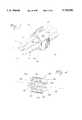
- FIG. 6is a perspective view of a base used in the clamp assembly
- FIG. 7is a side view of the base
- FIG. 8is a plan view of the base
- FIG. 9is a view of nested inserts used in a modification of the clamp assembly.
- FIG. 10is a perspective view of the nested inserts
- FIG. 11is a perspective view of one of the nested inserts
- FIG. 12is an end view of the nested insert
- FIG. 13is a plan view of the nested insert
- FIG. 14is a side view of the nested insert.
- FIG. 15is an end view of an insert for clamping a plurality of cables.
- FIGS. 1-8a clamp assembly 10 forming a first embodiment of the present invention is illustrated.
- the clamp assembly 10is particularly suited for clamping fiber optic cables 12 therein but, it will be understood that other cables, such as electrical conductors, air lines and the like could be clamped as well.
- the clamp assembly 10includes a clamp 14, seen in FIG. 1, which includes a first clamp half 16 and second clamp half 18 connected together by a hinge pin 20.
- the first clamp half 16can be seen to include a base portion 22, a hinge portion 24, a forward portion 26 and a fastening portion 28.
- Second clamp half 18is similarly constructed with a base portion 30, a hinge portion 32, a forward portion 34 and a fastening portion 36.
- the base portion 22 of first clamp half 16has a pair of countersunk apertures 38 therethrough to attach the first clamp half 16 to a fixed structure from which the cable or cables will be supported. Two flat head screws can fasten the first clamp half 16 to the support so it will not twist. While two apertures 38 are preferred to fasten the clamp to a support, a single aperture can be used or more than two apertures can be employed.
- the hinge portions 24 and 32can be seen to have mating elements receiving the hinge pin 20 to permit the second clamp half 18 to swing relative the first clamp half 16.
- the fastening portion 28 of first clamp half 16is provided with a permanently mounted threaded rod 40.
- the fastening portion 36 of second clamp half 18is provided with a circular notch 42 so that fastening portion 36 can be moved into contact with fastening portion 28 when the clamp is closed, as seen in FIG. 3.
- a nut 44can be threaded onto rod 40 to secure fastening portion 36 against fastening portion 28.
- aperturescan be formed through both fastening portions 28 and 36 and a separate bolt and nut combination used to hold the clamp in the closed position.
- each of the hinge portions 24 and 32has a square aperture 46 formed therethrough while each of the forward portions 26 and 34 has a square aperture 48 formed therethrough.
- the apertures 46 and 48 on each clamp halfare generally aligned.
- each clamp halfgenerally extends perpendicular from the base portion thereof.
- the forward portionextends at an obtuse angle from the base portion, for example 130°.
- the fastening portionextends from the forward portion in a plane generally parallel with the base portion.
- each clamputilizes two bases, one base received on each of the clamp halves.
- the bases as shownare identical.
- Base 50has an outer surface 52 and an inner surface 54.
- Outer surface 52is a series of planar surfaces including a base surface 56, slanted surfaces 58 and 60 and vertical surfaces 62 and 64.
- a tab 66extends outwardly from the slanted surface 60 while a snap fit lug 68 extends outwardly from the slanted surface 58.
- the inner surface 54is a portion of a cylinder having an arc less than 180° with a predetermined radius R centered along axis 70. Ridges 72 and 74 extend upwardly from the inner surface 54 and generally extend in a plane perpendicular the axis 70.
- a ridge 76extends upwardly from the inner surface 54 and extends generally parallel the axis 70.
- An aperture 78is formed into the base 50 through the inner surface 54.
- a notch 80is similarly formed into the base 50 at end 82 of the base through the inner surface 54.
- each base 50can be snap fit into a clamp half 16 and 18 by initially inserting the tab 66 into the square aperture 48 in the forward portion of the respective clamp half and snapping the snap fit lug 68 into the square aperture 46 of the hinge portion thereof. Thus, a base 50 will be secured firmly within each clamp half.
- the clamp assembly 10can clamp a cable 12 therein having an outer radius of approximately R.
- the ridges 72, 74 and 76will be forced into the sheath 84 of the cable 12 to enhance the clamping engagement between the clamp assembly 10 and the cable 12.
- a flexible insert 86can be employed with clamp 14 and bases 50 to clamp one or more cables mounted therein.
- the flexible insert 86is generally cylindrically shaped having an axis 88 with a core 94 concentric to axis 88 and five flexible spokes 90 extending radially outward from the core 94.
- Each spoke 90has a relatively thin section 92 extending out from the core 94 of the insert which transitions into a wider head 96.
- Each of the heads 96has an outer surface 100 which is curved about a radius R i centered on axis 88.
- individual cables 12can be fit through the slots between adjacent heads 96 and into the cylindrical cavities 102 formed between each adjacent spoke 90.
- the cavitiesare formed so that little, if any, portion of the cable 12 in a cavity extends radially outward from a cylinder of radius R i containing the surfaces 100.
- the flexible insert 86is formed of a material of sufficient flexibility so that the heads 96 and sections 92 will deform to allow a cable to be inserted into a cylindrical cavity 102.
- the cables and insertare positioned between the bases 50 and the clamp 14 is closed and tightened with nut 44 to clamp the cables therein.
- the dimensions of the clamp 14, bases 50 and flexible insert 86are such that when the clamp is closed, the bases 50 will somewhat compress the flexible insert 86 so that the flexible insert 86 is held tightly within the confines of the bases 50 and the individual cables 12 are held tightly within the individual cylindrical cavities 102 of the flexible insert 86.
- one of the heads 96can have an outer surface 100 with a protrusion 104 which can fit within the aperture 78 in one of the bases 50.
- Thisprovides a consistent orientation for the insert when a series of clamp assemblies 10 are used along the length of the cable. Also, it prevents twisting and sliding of the insert.
- each of the cablesis wrapped with electrician's tape until the outer diameter of the cable is such that the cable fits snugly into the cylindrical cavity 102.
- the flexible insertis shown with five cylindrical cavities to receive five cables, fewer cavities can be formed in the insert if, for example, only four or fewer cables are used or if the cables are larger in diameter. Further, more than five cylindrical cavities can be employed if the cable diameters are smaller.
- clamp assembly 10With reference now to FIGS. 9-14, a modification of clamp assembly 10 will be described.
- the clamp 14 and bases 50are also employed.
- the flexible insert 86is replaced by a series of nested inserts 106-116 which are each designed to fit a single cable of predetermined diameter.
- the inserts having an inner surface of diameter too small for the cableare removed and discarded until an insert having an inner surface with the proper diameter remains on each base 50 to clamp the cable therein.
- inserts 114 and 116can be removed from one base while inserts 112-116 are removed from the facing base to best accommodate a specific cable diameter.
- the largest nested insert 106will be described.
- the other nested inserts 108-116are essentially identical except for size.
- the nested insert 106has a semi-cylindrical shape which extends an arc of somewhat less than 180°.
- the outer surface 118has a series of notches 120 formed along the circumference of the outer surface 118 and a groove 122 along the length of the outer surface 118 to engage the ridges 72, 74 and 76 on a base 50.
- a notch 124is formed in first end 126 of the inserts which facilitates removal of the next smaller insert from its nested position within insert 106.
- the slots of each of the insertsalternate from end to end, as best seen in FIGS. 9 and 10. Insert 116 does not have a slot.
- the inner surface 128 of the insert 106has a cylindrical curvature corresponding to the radius of the particular cable to be received.
- the inner surfacehas circumferential ridges 130 and 132 and linear ridge 134 which are received in corresponding notches in the next smaller size insert.
- a protrusion 136extends from the outer surface 118 and is received in the aperture 78 in base 50.
- an aperture 138is formed in the insert 106 through the inner surface 128 to receive a matching protrusion 136 on the next smaller size insert 108.
- Insert 116does not have an aperture.
- the diameter of cable for which the insert is designedis printed on the edge 140 of the insert at label 142.
- the insertsare numbered sequentially, for example, from one to six, with the number imprinted on the inner surface for ready observation.
- the clamp 14is formed of metal.
- the bases 50are formed of plastic and have a radius R of 0.562 inch.
- the six insertsdecrease in radius of their inner surfaces from, in sequence, 0.5 inch, 0.44 inch, 0.38 inch, 0.32 inch, 0.26 inch and 0.200 inch. These sizes form an aperture with the facing inserts on both bases 50 of diameter one inch, 0.88 inch, 0.75 inch, 0.63 inch, 0.50 inch and 0.38 inch, respectively.
- this range of diameterswould be expected to accommodate any cable diameter within the range of 0.38 inch to 1.00 inch as well as slightly larger cables and smaller cables.
- electricians tapecan be used to build up the diameter of any smaller cable until clamp assembly 10 becomes effective.
- the nested insertsare formed of molded plastic, specifically polycarbonate. Each of the inserts has a thickness of about 0.060 inch and a length of about 0.9 inch.
- the flexible insertis made of a soft rubbery plastic such as Kraton and has a radius R i of 0.565 inch.
- Each of the cylindrical cavities 102is 0.4 inch in diameter.
- insert 150is mounted in each base 50 and replaces inserts 86 and 106-116.
- Each insert 150has a pair of semi-cylindrical cavities 152 formed therein. The cavities on the opposed inserts 150 are aligned to seize a pair of cables 12 therebetween when the clamp is closed.
- inserts 150can be modified to have three or more semi-cylindrical cavities, as desired, to hold three or more cables in line.
- strain relief clampsit is preferred to wrap several wraps of electrician's tape about the cable at the point to be clamped and pull the cable with tape wrap into the insert or base to wedge the cable therein to insure the most effective strain relief.
Landscapes
- Engineering & Computer Science (AREA)
- General Engineering & Computer Science (AREA)
- Physics & Mathematics (AREA)
- Mechanical Engineering (AREA)
- General Physics & Mathematics (AREA)
- Optics & Photonics (AREA)
- Installation Of Indoor Wiring (AREA)
Abstract
Description
This invention relates to the supporting of cables, such as optical cables, to provide strain relief.
When a cable, such as an optical fiber cable, is terminated in a junction box, or other device, it should be secured in such a way as to prevent any force applied to the cable from being transferred to the termination point. This is commonly referred to as strain relief. The absence of proper strain relief leaves the termination point vulnerable and unprotected, which could, in the event of an applied force on the cable, lead to partial or total loss of the cable's transmission performance.
A common method of strain relief is sheath retention. A clamp or tie is frictionally engaged with the outer sheath of the cable with the clamp or tie being secured to a fixed support. With tie wrapping, the cable is simply strapped to a fixed point using a tie wrap. Tie wrapping has the disadvantages of possible over-tightening of the tie wrap. If a tie wrap is tied too tightly, it may induce a loss of transmission performance, especially in fiber optic cables where microbending allows light to escape from the core, thereby degrading the signal. Cables with soft jackets are especially susceptible. This is a common problem since many craftsmen carry cable tie tools which, on the one hand, ease the installation of cable tie wraps, but unfortunately also tighten them very tight. Where many cables are terminated at a single point, the use of tie wrap often results in a messy jumble of cables since, unless a large area is available to which the cables may be individually tied down, the cables must be tied off in bundles or layers. In addition to lessening the neatness of the installation, this reduces the effectiveness of the strain relief since cables are more free to slide relative to the point of strain relief.
Another form of sheath retention strain relief is the use of clamps where the cable is squeezed inside a clamp or clam shell-like device. This has proven generally effective when used with fiber optic cables. However, clamps known in the industry accommodate only a single cable yet occupy a fairly large amount of space. This may be adequate for cable of larger fiber or conductor counts since a single cable may be capable of feeding a large service point, such as a connector or splice housing. However, if the same service point is fed by multiple smaller cables, this method requires a large number of clamps and thus a large amount of space in an environment which rarely has the space available.
In accordance with one aspect of the present invention, a clamp is provided for clamping a cable to a support. The clamp includes a first clamp half having a base, a hinged portion, a forward portion and a securing portion. A second clamp half is provided having a base, a hinged portion, a forward portion and a securing portion. The first and second clamp halves are hinged together at their hinge portions. The base of said first clamp half has at least one hole therethrough to receive a securing fastener to fasten the clamp to the support.
In accordance with another aspect of the present invention, a flexible insert is provided which has an outer circumference. A plurality of notches are formed in the insert opening through the outer circumference for receiving individual cables therein. The first and second clamp halves engage the flexible insert at the outer circumference.
In accordance with another aspect of the present invention, a first clamp base is provided which has a first projection engaging the forward portion of the first clamp half and a second projection engaging the hinge portion of the first clamp half, the first clamp base having an outer surface engaging the base of the first clamp half and a curved inner surface. The inner surface can be used to clamp to a cable or to receive an insert which, in turn, engages the cable.
In accordance with another aspect of the present invention, at least one insert is provided having a curved outer surface engaging the inner surface of the first clamp base and an inner surface curved to receive the cable. A plurality of nested inserts can be provided for selecting the cable size to be clamped.
A more complete understanding of the invention and its advantages will be apparent from the following detailed description when taken in conjunction with the accompanying drawings in which:
FIG. 1 is a perspective view of a clamp utilized in a first embodiment of the present invention;
FIG. 2 is an exploded view of a clamp assembly forming first embodiment of the present invention with a flexible insert;
FIG. 3 is a perspective view of the clamp assembly of FIG. 2 clamping cables therein;
FIG. 4 is a perspective view of a flexible insert used in the clamp assembly;
FIG. 5 is an end view of the flexible insert;
FIG. 6 is a perspective view of a base used in the clamp assembly;
FIG. 7 is a side view of the base;
FIG. 8 is a plan view of the base;
FIG. 9 is a view of nested inserts used in a modification of the clamp assembly;
FIG. 10 is a perspective view of the nested inserts;
FIG. 11 is a perspective view of one of the nested inserts;
FIG. 12 is an end view of the nested insert;
FIG. 13 is a plan view of the nested insert;
FIG. 14 is a side view of the nested insert; and
FIG. 15 is an end view of an insert for clamping a plurality of cables.
Referring now to the drawings, wherein like reference characters designate like or corresponding parts throughout several views, and in particular to FIGS. 1-8, aclamp assembly 10 forming a first embodiment of the present invention is illustrated. Theclamp assembly 10 is particularly suited for clamping fiberoptic cables 12 therein but, it will be understood that other cables, such as electrical conductors, air lines and the like could be clamped as well.
Theclamp assembly 10 includes aclamp 14, seen in FIG. 1, which includes afirst clamp half 16 andsecond clamp half 18 connected together by ahinge pin 20. Thefirst clamp half 16 can be seen to include abase portion 22, ahinge portion 24, aforward portion 26 and afastening portion 28.Second clamp half 18 is similarly constructed with abase portion 30, ahinge portion 32, aforward portion 34 and afastening portion 36. Thebase portion 22 offirst clamp half 16 has a pair ofcountersunk apertures 38 therethrough to attach thefirst clamp half 16 to a fixed structure from which the cable or cables will be supported. Two flat head screws can fasten thefirst clamp half 16 to the support so it will not twist. While twoapertures 38 are preferred to fasten the clamp to a support, a single aperture can be used or more than two apertures can be employed.
Thehinge portions hinge pin 20 to permit thesecond clamp half 18 to swing relative thefirst clamp half 16.
The fasteningportion 28 offirst clamp half 16 is provided with a permanently mounted threadedrod 40. Thefastening portion 36 ofsecond clamp half 18 is provided with acircular notch 42 so thatfastening portion 36 can be moved into contact withfastening portion 28 when the clamp is closed, as seen in FIG. 3. Anut 44 can be threaded ontorod 40 to securefastening portion 36 againstfastening portion 28. Alternatively, apertures can be formed through both fasteningportions
As can be seen in FIG. 1, each of thehinge portions square aperture 46 formed therethrough while each of theforward portions square aperture 48 formed therethrough. Theapertures
The hinge portion of each clamp half generally extends perpendicular from the base portion thereof. The forward portion, however, extends at an obtuse angle from the base portion, for example 130°. The fastening portion extends from the forward portion in a plane generally parallel with the base portion.
With reference to FIGS. 2 and 6-8, the base 50 mounted in theclamp 14 will be described. Each clamp utilizes two bases, one base received on each of the clamp halves. The bases as shown are identical.
As can be understood from FIGS. 2 and 3, each base 50 can be snap fit into aclamp half tab 66 into thesquare aperture 48 in the forward portion of the respective clamp half and snapping the snapfit lug 68 into thesquare aperture 46 of the hinge portion thereof. Thus, abase 50 will be secured firmly within each clamp half.
With the assembly as described, theclamp assembly 10 can clamp acable 12 therein having an outer radius of approximately R. Theridges sheath 84 of thecable 12 to enhance the clamping engagement between theclamp assembly 10 and thecable 12.
With reference to FIGS. 2 and 5, aflexible insert 86 can be employed withclamp 14 andbases 50 to clamp one or more cables mounted therein. Theflexible insert 86 is generally cylindrically shaped having anaxis 88 with a core 94 concentric toaxis 88 and fiveflexible spokes 90 extending radially outward from thecore 94. Each spoke 90 has a relativelythin section 92 extending out from thecore 94 of the insert which transitions into awider head 96. Each of theheads 96 has anouter surface 100 which is curved about a radius Ri centered onaxis 88.
As can be seen in FIG. 3,individual cables 12 can be fit through the slots betweenadjacent heads 96 and into thecylindrical cavities 102 formed between eachadjacent spoke 90. The cavities are formed so that little, if any, portion of thecable 12 in a cavity extends radially outward from a cylinder of radius Ri containing thesurfaces 100. Theflexible insert 86 is formed of a material of sufficient flexibility so that theheads 96 andsections 92 will deform to allow a cable to be inserted into acylindrical cavity 102.
When the cables to be strain relieved have been entered into the cavities, and it is clear from the figures that anywhere from one to five cables can be accommodated by theflexible insert 86 illustrated, the cables and insert are positioned between thebases 50 and theclamp 14 is closed and tightened withnut 44 to clamp the cables therein. Preferably, the dimensions of theclamp 14,bases 50 andflexible insert 86 are such that when the clamp is closed, thebases 50 will somewhat compress theflexible insert 86 so that theflexible insert 86 is held tightly within the confines of thebases 50 and theindividual cables 12 are held tightly within the individualcylindrical cavities 102 of theflexible insert 86.
As can best be seen in FIGS. 4 and 5, one of theheads 96 can have anouter surface 100 with aprotrusion 104 which can fit within theaperture 78 in one of thebases 50. This provides a consistent orientation for the insert when a series ofclamp assemblies 10 are used along the length of the cable. Also, it prevents twisting and sliding of the insert. Preferably, each of the cables is wrapped with electrician's tape until the outer diameter of the cable is such that the cable fits snugly into thecylindrical cavity 102. Of course, while the flexible insert is shown with five cylindrical cavities to receive five cables, fewer cavities can be formed in the insert if, for example, only four or fewer cables are used or if the cables are larger in diameter. Further, more than five cylindrical cavities can be employed if the cable diameters are smaller.
With reference now to FIGS. 9-14, a modification ofclamp assembly 10 will be described. In the modification, theclamp 14 andbases 50 are also employed. However, theflexible insert 86 is replaced by a series of nested inserts 106-116 which are each designed to fit a single cable of predetermined diameter. As will be clear from the discussion below, when sizing theclamp assembly 10 for a particular cable, the inserts having an inner surface of diameter too small for the cable are removed and discarded until an insert having an inner surface with the proper diameter remains on each base 50 to clamp the cable therein. With the six sizes of nested inserts illustrated, a wide range of cable diameters can be accommodated, from the smallest cable that will be secured by thesmallest inserts 116 to the largest cable that will be secured by the diameter of thebases 50 if all six inserts are removed from the bases. An unequal number of inserts can be removed from thebases 50 to tailor theclamp assembly 10 to a specific cable. For example, inserts 114 and 116 can be removed from one base while inserts 112-116 are removed from the facing base to best accommodate a specific cable diameter.
With reference to FIGS. 11-14, the largest nestedinsert 106 will be described. The other nested inserts 108-116 are essentially identical except for size.
The nestedinsert 106 has a semi-cylindrical shape which extends an arc of somewhat less than 180°. Theouter surface 118 has a series ofnotches 120 formed along the circumference of theouter surface 118 and a groove 122 along the length of theouter surface 118 to engage theridges base 50. Anotch 124 is formed infirst end 126 of the inserts which facilitates removal of the next smaller insert from its nested position withininsert 106. When nested, the slots of each of the inserts alternate from end to end, as best seen in FIGS. 9 and 10.Insert 116 does not have a slot.
Theinner surface 128 of theinsert 106 has a cylindrical curvature corresponding to the radius of the particular cable to be received. The inner surface hascircumferential ridges linear ridge 134 which are received in corresponding notches in the next smaller size insert.
Aprotrusion 136 extends from theouter surface 118 and is received in theaperture 78 inbase 50. Similarly, anaperture 138 is formed in theinsert 106 through theinner surface 128 to receive amatching protrusion 136 on the nextsmaller size insert 108.Insert 116 does not have an aperture. For convenience, the diameter of cable for which the insert is designed is printed on theedge 140 of the insert atlabel 142. Also, preferably, the inserts are numbered sequentially, for example, from one to six, with the number imprinted on the inner surface for ready observation.
By positioning theaperture 138 adjacent thefirst end 126 of each of the inserts, and the protrusion near the opposite end, it can be seen that the inserts are alternately stacked as shown in FIGS. 9 and 10 so that a fingernail, screwdriver tip or other suitable object can be fit within one of the slots to remove the inserts which are too small for the particular installation. Thus notches and ridges oninserts near end 126 while oninserts
In oneclamp assembly 10 formed in accordance with the teachings of the present invention, theclamp 14 is formed of metal. Thebases 50 are formed of plastic and have a radius R of 0.562 inch. The six inserts decrease in radius of their inner surfaces from, in sequence, 0.5 inch, 0.44 inch, 0.38 inch, 0.32 inch, 0.26 inch and 0.200 inch. These sizes form an aperture with the facing inserts on bothbases 50 of diameter one inch, 0.88 inch, 0.75 inch, 0.63 inch, 0.50 inch and 0.38 inch, respectively. As noted, this range of diameters would be expected to accommodate any cable diameter within the range of 0.38 inch to 1.00 inch as well as slightly larger cables and smaller cables. Of course, electricians tape can be used to build up the diameter of any smaller cable untilclamp assembly 10 becomes effective. The nested inserts are formed of molded plastic, specifically polycarbonate. Each of the inserts has a thickness of about 0.060 inch and a length of about 0.9 inch. The flexible insert is made of a soft rubbery plastic such as Kraton and has a radius Ri of 0.565 inch. Each of thecylindrical cavities 102 is 0.4 inch in diameter.
With reference now to FIG. 15, a second modification of the present invention is illustrated. In this modification, aninsert 150 is mounted in each base 50 and replacesinserts 86 and 106-116. Eachinsert 150 has a pair ofsemi-cylindrical cavities 152 formed therein. The cavities on theopposed inserts 150 are aligned to seize a pair ofcables 12 therebetween when the clamp is closed. As can be readily understood, inserts 150 can be modified to have three or more semi-cylindrical cavities, as desired, to hold three or more cables in line.
With all of the variations of strain relief clamps noted, it is preferred to wrap several wraps of electrician's tape about the cable at the point to be clamped and pull the cable with tape wrap into the insert or base to wedge the cable therein to insure the most effective strain relief.
Although several embodiments of the present invention have been illustrated in the accompany drawings and described in the foregoing Detailed Description, it will be understood that the invention is not limited to the embodiments disclosed, but is capable of numerous rearrangements, modifications, and substitutions of parts and elements without departing from the scope and spirit of the invention.
Claims (25)
1. A clamp for clamping a cable to a support, comprising:
a first clamp half having a base, a hinge portion, a forward portion and a securing portion, the base of said first clamp half having at least one hole therethrough to receive a securing fastener to fasten the clamp to the support;
a second clamp half having a base, a hinge portion, a forward portion and a securing portion;
the first and second clamp halves hinged together at their hinge portions and movable relative each other between an open and closed position; and
a member between said clamp halves, said member having a surface for strain relief engagement with said cable with the clamp halves in the closed position.
2. The clamp of claim 1 wherein the member includes a flexible insert having an outer circumference and a plurality of notches formed in the insert, said notches opening through the outer circumference for receiving individual cables therein, the first and second clamp halves engaging the flexible insert at the outer circumference to secure the cables therein in the closed position.
3. The clamp of claim 2 wherein the flexible insert has a projection extending from the outer circumference to orient the flexible insert relative the first and second clamp halves.
4. The clamp of claim 1 wherein the member includes a clamp base mounted on each of said clamp halves, each of said clamp bases having a first projection engaging the forward portion and a second projection engaging the hinge portion, the base having a outer surface engaging the base of the clamp half and a curved inner surface.
5. The clamp of claim 4 wherein the clamp base has at least one ridge extending from the curved inner surface thereof.
6. The clamp of claim 4 wherein the member further includes at least one insert having a curved outer surface engaging the inner surface of the clamp base and an inner surface curved to receive the cable.
7. The clamp of claim 6 wherein said first insert has at least one notch formed in the outer surface thereof, the clamp base having at least one ridge formed in the inner surface thereof, the ridge entering the notch of the first insert.
8. The clamp of claim 6 wherein the first insert has an extension extending from the outer surface thereof, the base having an aperture formed through the inner surface thereof receiving the extension on the first insert.
9. The clamp of claim 6 wherein the first insert has a first end, a notch formed in the first end.
10. The clamp of claim 6 further comprising a second insert having a curved outer surface engaging the inner surface on the first insert and an inner surface curved to receive a cable.
11. The clamp of claim 1 wherein the base of the first clamp half has a plurality of apertures, the apertures being countersunk.
12. The clamp of claim 1 wherein the hinge portion and forward portion of each of said clamp halves has an aperture formed therethrough.
13. The clamp of claim 1 wherein the securing portion of the first clamp half has a threaded rod thereon and the securing portion of the second clamp half has a cutout to receive the threaded rod, the clamp further having a threaded nut for threading on the rod to secure the clamp in a closed position.
14. The clamp of claim 2, wherein the flexible insert is made of thermoplastic rubber.
15. A method for clamping a cable within a clamp, comprising the steps of:
placing the cable between a first clamp half having a portion and a second clamp half having a base, a hinge portion, a forward portion and a securing portion, the first and second clamp halves hinged together at their hinge portions and movable relative each other between an open and closed position;
moving the first and second clamp halves together to the closed position;
securing the base of the first clamp half to a fixed support; and
removing nested inserts from each clamp half until an insert is exposed having an inner surface with diameter corresponding to the diameter of the cable to be clamped.
16. The method of claim 15 further comprising the steps of securing the first clamp half to the support by at least two fasteners.
17. The method of claim 16 further comprising the step of orienting the flexible insert with a projection extending therefrom.
18. The method of claim 15 further comprising the step of:
inserting at least one cable within a cylindrical aperture formed through the outer surface of a flexible insert; and
placing the flexible insert and cable therein between the first and second clamp halves.
19. The method of claim 18 further comprising the steps of:
inserting a plurality of cables within cylindrical cavities opening through the outer surface of the flexible insert.
20. The method of claim 15 further comprising the step of:
mounting a clamp base on each of said first and second clamp halves, the clamp base having a first projection and a second projection by inserting the first projection of each clamp base in an aperture provided in the forward portion and the second projection of the clamp base within an aperture in the hinge portion to secure the clamp base within the clamp halves.
21. The method of claim 15 further comprising the step of clamping a fiber optic cable between the first and second clamping halves.
22. A clamp for clamping a cable to a support, comprising;
a first clamp half having a base, a hinge portion, a forward portion and a securing portion;
a second clamp half having a base, a hinge portion, a forward portion and a securing portion;
the first and second clamp halves hinged together at their hinge portions and movable relative each other between an open and closed position;
a member between said clamp halves, said member having a surface for strain relief engagement with said cable with the clamp halves in the closed position; and
wherein the member includes a clamp base mounted on each of said clamp halves, each of said clamp bases having a first projection engaging the forward portion and a second projection engaging the hinge portion, the base having a outer surface engaging the base of the clamp half and a curved inner surface.
23. A clamp for clamping a cable to a support, comprising;
a first clamp half having a base, a hinge portion, a forward portion and a securing portion;
a second clamp half having a base, a hinge portion, a forward portion and a securing portion;
the first and second clamp halves hinged together at their hinge portions and movable relative each other between an open and closed position;
a member between said clamp halves, said member having a surface for strain relief engagement with said cable with the clamp halves in the closed position; and
wherein the hinge portion and forward portion of each of said clamp halves has an aperture formed therethrough.
24. A clamp for clamping a cable to a support, comprising;
a first clamp half having a base, a hinge portion, a forward portion and a securing portion;
a second clamp half having a base, a hinge portion, a forward portion and a securing portion;
the first and second clamp halves hinged together at their hinge portions and movable relative each other between an open and closed position;
a member between said clamp halves, said member having a surface for strain relief engagement with said cable with the clamp halves in the closed position; and
wherein the securing portion of the first clamp half has a threaded rod thereon and the securing portion of the second clamp half has a cutout to receive the threaded rod, the clamp further having a threaded nut for threading on the rod to secure the clamp in a closed position.
25. A method for clamping a cable within a clamp, comprising the steps of:
placing the cable between a first clamp half having a base, a hinge portion, a forward portion and a securing portion and a second clamp half having a base, a hinge portion, a forward portion and a securing portion, the first and second clamp halves hinged together at their hinge portions and movable relative each other between an open and closed position;
moving the first and second clamp halves together to the closed position;
securing the base of the first clamp half to a fixed support; and
mounting a clamp base on each of said first and second clamp halves, the clamp base having the first projection and a second projection by inserting the first projection of each clamp base in an aperture provided in the forward portion and the second projection of the clamp base within an aperture in the hinge portion to secure the clamp base within the clamp halves.
Priority Applications (1)
| Application Number | Priority Date | Filing Date | Title |
|---|---|---|---|
| US08/756,320US5742982A (en) | 1996-11-25 | 1996-11-25 | Cable strain relief apparatus |
Applications Claiming Priority (1)
| Application Number | Priority Date | Filing Date | Title |
|---|---|---|---|
| US08/756,320US5742982A (en) | 1996-11-25 | 1996-11-25 | Cable strain relief apparatus |
Publications (1)
| Publication Number | Publication Date |
|---|---|
| US5742982Atrue US5742982A (en) | 1998-04-28 |
Family
ID=25042971
Family Applications (1)
| Application Number | Title | Priority Date | Filing Date |
|---|---|---|---|
| US08/756,320Expired - LifetimeUS5742982A (en) | 1996-11-25 | 1996-11-25 | Cable strain relief apparatus |
Country Status (1)
| Country | Link |
|---|---|
| US (1) | US5742982A (en) |
Cited By (135)
| Publication number | Priority date | Publication date | Assignee | Title |
|---|---|---|---|---|
| US6135398A (en)* | 1997-12-19 | 2000-10-24 | Alcoa Fujikura Limited | Trunion clamp for optical fiber |
| WO2001053859A1 (en)* | 2000-01-24 | 2001-07-26 | Electric Motion Company, Inc. | Fiber optic shield connector |
| US6349912B1 (en)* | 1999-03-27 | 2002-02-26 | De-Sta-Co Metallerzeugnisse Gmbh | Supporting structure |
| US20020028056A1 (en)* | 2000-09-01 | 2002-03-07 | Edwin Fontecha | Apparatus and method to vertically route and connect multiple optical fibers |
| US20020062537A1 (en)* | 2000-11-01 | 2002-05-30 | International Business Machines Corporation | Device and method for identifying cables |
| WO2002019003A3 (en)* | 2000-09-01 | 2003-07-03 | Lightwave Microsystems Corp | Apparatus and method to vertically route and connect multiple optical fibers |
| US6622585B1 (en)* | 1998-10-16 | 2003-09-23 | Abb Ab | Industrial robot and cable guiding device for this robot and use of the device |
| US20030189149A1 (en)* | 2002-04-05 | 2003-10-09 | Leffers Murray Jones | Multiple writing, drafting and art instrument holder |
| US6699063B2 (en) | 2001-02-14 | 2004-03-02 | Roland Lebender | Cable assembly having strain relief mechanism and housing incorporating such cable assembly |
| US6710249B1 (en)* | 2002-09-13 | 2004-03-23 | Sandra L. Denton | Wire separator |
| US6752360B2 (en)* | 2002-08-14 | 2004-06-22 | Deere & Company | Hydraulic hose holder for an agricultural implement |
| US20040144555A1 (en)* | 2002-11-30 | 2004-07-29 | Valere Buekers | Longitudinally activated compression sealing device for elongate members and methods for using the same |
| US6781058B1 (en)* | 2003-02-20 | 2004-08-24 | Stoneridge Inc., Alphabet Division | Cable guide assembly for a vehicle sliding door |
| US20040179900A1 (en)* | 2003-02-27 | 2004-09-16 | Masaaki Uematsu | Device for laying line elements |
| US6868580B1 (en) | 2002-06-19 | 2005-03-22 | Northrop Grumman Corporation | Self-locating fastener and method |
| US20050111810A1 (en)* | 2003-11-26 | 2005-05-26 | Giraud William J. | Connector housing for a communication network |
| US20050111809A1 (en)* | 2003-11-26 | 2005-05-26 | Giraud William J. | Connector housing having a sliding tray with a hingeable portion |
| US6926237B2 (en) | 2003-05-29 | 2005-08-09 | Illinois Tool Works Inc. | Vibration damping clip |
| US20050224677A1 (en)* | 2004-03-08 | 2005-10-13 | Airbus Deutschland Gmbh | Holder for holding and guiding bundles of cables in aircraft |
| US20050230588A1 (en)* | 2004-04-16 | 2005-10-20 | Line-Ching Lu | Hanging device for suitcase |
| WO2006007699A1 (en)* | 2004-07-16 | 2006-01-26 | Matthew Kennedy | Wire management device |
| US20060081744A1 (en)* | 2004-10-15 | 2006-04-20 | Konold Donald R | Configurable clamp assembly |
| US20060157235A1 (en)* | 2004-10-07 | 2006-07-20 | Oceanworks International, Inc. | Termination for segmented steel tube bundle |
| US20060237217A1 (en)* | 2005-04-25 | 2006-10-26 | Cable Components Group, Llc. | Variable diameter conduit tubes for high performance, multi-media communication cable |
| US20060237218A1 (en)* | 2005-04-25 | 2006-10-26 | Cable Components Group, Llc. | High performance, multi-media cable support-separator facilitating insertion and removal of conductive media |
| US20070007397A1 (en)* | 2005-07-07 | 2007-01-11 | Panduit Corp. | Cable bracket and strap assembly |
| US20070057614A1 (en)* | 2003-06-25 | 2007-03-15 | Koplin Zenon S | Stabilizing device, fluorescent lamp comprising such a device, and method of reinforcing a fluorescent lamp |
| US20070079969A1 (en)* | 2005-10-06 | 2007-04-12 | Ocean Works International, Inc. | Segmented steel tube bundle termination assembly |
| US20080050083A1 (en)* | 2006-08-25 | 2008-02-28 | Frazier Brent M | Fiber optic housing assembly for fiber optic connections comprising pivotable portion |
| US20080230657A1 (en)* | 2007-03-22 | 2008-09-25 | Ellis Patents Limited | Cable clamp |
| US20090026323A1 (en)* | 2007-07-23 | 2009-01-29 | Panduit Corp. | Network Cable Bundling Tool |
| US20090026328A1 (en)* | 2007-07-25 | 2009-01-29 | Gallardo Luis E | Shower bracket |
| US20090078332A1 (en)* | 2007-09-10 | 2009-03-26 | Delallo Linda M | Electrical cord straightening device |
| US20090140108A1 (en)* | 2007-12-03 | 2009-06-04 | International Engine Intellectual Property Company, Llc | Multiple tube clip |
| US20090152407A1 (en)* | 2004-12-08 | 2009-06-18 | Tomas Kreutz | Frame And Method Of Comprising One or More Elastic Modules for Cable Entries,Pipe Penetrations or The Like |
| US20090205866A1 (en)* | 2007-11-27 | 2009-08-20 | Jarle Jansen Bremnes | Electric three-phase power cable system |
| US20090310928A1 (en)* | 2008-06-12 | 2009-12-17 | Wolf Kluwe | Universal cable bracket |
| GB2464680A (en)* | 2008-10-21 | 2010-04-28 | Tyco Electronics Raychem Nv | Cable retention clip. |
| US20100180408A1 (en)* | 2009-01-21 | 2010-07-22 | Peter Denning | Quick connect & release clamping system |
| US20100206586A1 (en)* | 2009-02-13 | 2010-08-19 | The Board Of Regents Of The Nevada System Of Higher Education, | Sampling system and method |
| US20100269313A1 (en)* | 2009-04-22 | 2010-10-28 | Paul Thomas Bruss | Clamp assembly |
| EP2284588A1 (en)* | 2009-08-10 | 2011-02-16 | The Boeing Company | Apparatus and method for establishing an optical path spanning a discontinuity in an optical channel |
| US20110042529A1 (en)* | 2009-08-24 | 2011-02-24 | Walter Thomas Alan | Routing assembly for wires in electronic assemblies and the like |
| US20110147543A1 (en)* | 2008-09-30 | 2011-06-23 | Toshiba Mitsubishi-Electric Indus. Sys. Corp. | Wire holder and wire bundling structure |
| US7997923B1 (en) | 2010-06-02 | 2011-08-16 | Tyco Electronics Corporation | Cable organizer for a connector assembly |
| US20110214949A1 (en)* | 2008-11-11 | 2011-09-08 | Christopher Gavin Brickell | Stabilization devices |
| US20110240341A1 (en)* | 2010-04-06 | 2011-10-06 | Google Inc. | Cooling disc for bundles of current carrying cables |
| US20110290951A1 (en)* | 2010-05-28 | 2011-12-01 | Airbus Operations Gmbh | Cable management device for bundles of cables in an aircraft |
| US20120292460A1 (en)* | 2011-05-19 | 2012-11-22 | Wanho T Manufacturing Co., Ltd. | Organizing device for cable and wire |
| US20120297574A1 (en)* | 2011-05-24 | 2012-11-29 | Jason Cameron Payne | Strain relief insert |
| EP2579078A1 (en)* | 2011-10-05 | 2013-04-10 | CCS Technology, Inc. | Strain relief device for optical fiber bundles and splice cassette for optical fibers |
| US8433171B2 (en) | 2009-06-19 | 2013-04-30 | Corning Cable Systems Llc | High fiber optic cable packing density apparatus |
| US20130187012A1 (en)* | 2012-01-19 | 2013-07-25 | Airbus Operations Limited | Cable retainer |
| US20130214100A1 (en)* | 2012-02-20 | 2013-08-22 | Airbus Operations Limited | Clamp block assembly |
| US8538226B2 (en) | 2009-05-21 | 2013-09-17 | Corning Cable Systems Llc | Fiber optic equipment guides and rails configured with stopping position(s), and related equipment and methods |
| US8542973B2 (en) | 2010-04-23 | 2013-09-24 | Ccs Technology, Inc. | Fiber optic distribution device |
| JP2013217411A (en)* | 2012-04-05 | 2013-10-24 | Mirai Ind Co Ltd | Wiring/piping material arranging tool |
| US8593828B2 (en) | 2010-02-04 | 2013-11-26 | Corning Cable Systems Llc | Communications equipment housings, assemblies, and related alignment features and methods |
| US8625950B2 (en) | 2009-12-18 | 2014-01-07 | Corning Cable Systems Llc | Rotary locking apparatus for fiber optic equipment trays and related methods |
| US8660397B2 (en) | 2010-04-30 | 2014-02-25 | Corning Cable Systems Llc | Multi-layer module |
| US8662760B2 (en) | 2010-10-29 | 2014-03-04 | Corning Cable Systems Llc | Fiber optic connector employing optical fiber guide member |
| US20140061393A1 (en)* | 2012-09-04 | 2014-03-06 | II Louis Cripps | Multiple axis control suspension system and method |
| US8699838B2 (en) | 2009-05-14 | 2014-04-15 | Ccs Technology, Inc. | Fiber optic furcation module |
| US20140102757A1 (en)* | 2012-09-04 | 2014-04-17 | The Boeing Company | Lightning Protection for Spaced Electrical Bundles |
| US8705926B2 (en) | 2010-04-30 | 2014-04-22 | Corning Optical Communications LLC | Fiber optic housings having a removable top, and related components and methods |
| US8712206B2 (en) | 2009-06-19 | 2014-04-29 | Corning Cable Systems Llc | High-density fiber optic modules and module housings and related equipment |
| US8718436B2 (en) | 2010-08-30 | 2014-05-06 | Corning Cable Systems Llc | Methods, apparatuses for providing secure fiber optic connections |
| CN103775741A (en)* | 2014-02-24 | 2014-05-07 | 国家电网公司 | Pipeline gatherer |
| US8805153B2 (en) | 2011-09-16 | 2014-08-12 | Adc Telecommunications, Inc. | Systems and methods for the management of fiber optic cables |
| US8879881B2 (en) | 2010-04-30 | 2014-11-04 | Corning Cable Systems Llc | Rotatable routing guide and assembly |
| US20140332249A1 (en)* | 2013-05-08 | 2014-11-13 | Kyle Steven Barna | Quick-release cord grip |
| US8913866B2 (en) | 2010-03-26 | 2014-12-16 | Corning Cable Systems Llc | Movable adapter panel |
| US20150001351A1 (en)* | 2013-06-27 | 2015-01-01 | Justin Krager | Cable retention system |
| US20150034776A1 (en)* | 2013-07-31 | 2015-02-05 | Stryker Corporation | Line management device |
| US8953924B2 (en) | 2011-09-02 | 2015-02-10 | Corning Cable Systems Llc | Removable strain relief brackets for securing fiber optic cables and/or optical fibers to fiber optic equipment, and related assemblies and methods |
| US8989547B2 (en) | 2011-06-30 | 2015-03-24 | Corning Cable Systems Llc | Fiber optic equipment assemblies employing non-U-width-sized housings and related methods |
| US8985862B2 (en) | 2013-02-28 | 2015-03-24 | Corning Cable Systems Llc | High-density multi-fiber adapter housings |
| US8995812B2 (en) | 2012-10-26 | 2015-03-31 | Ccs Technology, Inc. | Fiber optic management unit and fiber optic distribution device |
| US9008485B2 (en) | 2011-05-09 | 2015-04-14 | Corning Cable Systems Llc | Attachment mechanisms employed to attach a rear housing section to a fiber optic housing, and related assemblies and methods |
| US9020320B2 (en) | 2008-08-29 | 2015-04-28 | Corning Cable Systems Llc | High density and bandwidth fiber optic apparatuses and related equipment and methods |
| US20150115110A1 (en)* | 2013-10-31 | 2015-04-30 | Ernest Kalani Makainai | Monofilament Line Holders for Grass Trimmers |
| US9022814B2 (en) | 2010-04-16 | 2015-05-05 | Ccs Technology, Inc. | Sealing and strain relief device for data cables |
| US9036323B1 (en) | 2012-09-04 | 2015-05-19 | The Boeing Company | Power feeder shielding for electromagnetic protection |
| WO2015073378A1 (en)* | 2013-11-15 | 2015-05-21 | Newport Corporation | Flexure-type strain relief device |
| US9038832B2 (en) | 2011-11-30 | 2015-05-26 | Corning Cable Systems Llc | Adapter panel support assembly |
| US9042702B2 (en) | 2012-09-18 | 2015-05-26 | Corning Cable Systems Llc | Platforms and systems for fiber optic cable attachment |
| US9059578B2 (en) | 2009-02-24 | 2015-06-16 | Ccs Technology, Inc. | Holding device for a cable or an assembly for use with a cable |
| US9075216B2 (en) | 2009-05-21 | 2015-07-07 | Corning Cable Systems Llc | Fiber optic housings configured to accommodate fiber optic modules/cassettes and fiber optic panels, and related components and methods |
| US9075217B2 (en) | 2010-04-30 | 2015-07-07 | Corning Cable Systems Llc | Apparatuses and related components and methods for expanding capacity of fiber optic housings |
| US20150204462A1 (en)* | 2014-01-22 | 2015-07-23 | Hutchinson Wire Solutions, LLC | Devices, systems, and methods to secure wires and prevent wire theft |
| GB2522472A (en)* | 2014-01-27 | 2015-07-29 | Epsilon Optics Aerospace Ltd | A method and apparatus for a structural monitoring device adapted to be locatable within a tubular structure |
| US9112343B1 (en)* | 2012-09-04 | 2015-08-18 | The Boeing Company | Power feeder shielding for electromagnetic protection |
| US9213161B2 (en) | 2010-11-05 | 2015-12-15 | Corning Cable Systems Llc | Fiber body holder and strain relief device |
| US9250409B2 (en) | 2012-07-02 | 2016-02-02 | Corning Cable Systems Llc | Fiber-optic-module trays and drawers for fiber-optic equipment |
| US9279951B2 (en) | 2010-10-27 | 2016-03-08 | Corning Cable Systems Llc | Fiber optic module for limited space applications having a partially sealed module sub-assembly |
| US20160067870A1 (en)* | 2014-09-05 | 2016-03-10 | Fanuc Corporation | Umbilical member clamping device for clamping umbilical members via elastic body |
| US9291791B2 (en) | 2013-03-13 | 2016-03-22 | Commscope Technologies Llc | Anchoring cables to rack with self-locking cable clamp arrangements |
| US20160124172A1 (en)* | 2014-11-03 | 2016-05-05 | Gary Evan Miller | Panel-mountable fiber optic cable feedthrough |
| US9360648B2 (en) | 2011-09-16 | 2016-06-07 | Commscope Technologies Llc | Systems and methods for the management of fiber optic cables |
| US9438021B2 (en) | 2013-10-28 | 2016-09-06 | Wanho T Manufacturing Co., Ltd. | Organizing device for cable and wire |
| US9450389B2 (en) | 2013-03-05 | 2016-09-20 | Yaroslav A. Pichkur | Electrical power transmission system and method |
| US9519118B2 (en) | 2010-04-30 | 2016-12-13 | Corning Optical Communications LLC | Removable fiber management sections for fiber optic housings, and related components and methods |
| US20160365166A1 (en)* | 2015-06-12 | 2016-12-15 | Yazaki Corporation | Electric wire holding member and wire harness |
| USD779313S1 (en)* | 2008-07-04 | 2017-02-21 | Daiwa Kasei Kogyo Kabushiki Kaisha | Cushion clip |
| US9632270B2 (en) | 2010-04-30 | 2017-04-25 | Corning Optical Communications LLC | Fiber optic housings configured for tool-less assembly, and related components and methods |
| US9645317B2 (en) | 2011-02-02 | 2017-05-09 | Corning Optical Communications LLC | Optical backplane extension modules, and related assemblies suitable for establishing optical connections to information processing modules disposed in equipment racks |
| US9682759B1 (en)* | 2016-03-18 | 2017-06-20 | T-H Marine Supplies, Inc. | Trolling motor lift cord clamp device |
| US9720195B2 (en) | 2010-04-30 | 2017-08-01 | Corning Optical Communications LLC | Apparatuses and related components and methods for attachment and release of fiber optic housings to and from an equipment rack |
| US20170252931A1 (en)* | 2014-11-19 | 2017-09-07 | Abb Schweiz Ag | Cable-management system, a rotary joint and a robot |
| US20170269319A1 (en)* | 2015-11-02 | 2017-09-21 | Gary Evan Miller | Panel-mountable fiber optic cable feedthrough |
| US9971120B2 (en) | 2012-10-31 | 2018-05-15 | Commscope Technologies Llc | Anchoring cables to rack with cable clamp arrangements |
| US10060557B2 (en) | 2014-03-26 | 2018-08-28 | Superior Tray Systems Inc. | Cable pass through sealing systems |
| US10094491B1 (en) | 2017-10-17 | 2018-10-09 | Wanho T Manufacturing Co., Ltd. | Organizing device for cable and wire |
| US10094996B2 (en) | 2008-08-29 | 2018-10-09 | Corning Optical Communications, Llc | Independently translatable modules and fiber optic equipment trays in fiber optic equipment |
| US20190039747A1 (en)* | 2017-08-03 | 2019-02-07 | The Boeing Company | Transport Element Clamp System |
| NO20171464A1 (en)* | 2017-09-12 | 2019-03-13 | Oeglaend System As | System and method for attaching wires |
| US20190124906A1 (en)* | 2016-04-18 | 2019-05-02 | Safe Passage Pty Ltd | A storage device |
| US20190137008A1 (en)* | 2017-11-09 | 2019-05-09 | R.A. Phillips Industries, Inc. | Conduit clamp |
| US10293769B2 (en) | 2016-04-28 | 2019-05-21 | Cnh Industrial America Llc | Routing and securing system with nested support arrangement |
| US10428974B2 (en) | 2016-04-28 | 2019-10-01 | Cnh Industrial America Llc | System for routing and securing elongate routed components of a vehicle |
| US20200038131A1 (en)* | 2017-02-10 | 2020-02-06 | Maurice Andre Recanati | Cable, wire and tube organizer for laparoscopic and hysteroscopic surgery |
| US10582981B2 (en) | 2016-02-02 | 2020-03-10 | Stryker Corporation | Accessory support and coupling systems for an accessory support |
| US20200233170A1 (en)* | 2017-10-17 | 2020-07-23 | Corning Research & Development Corporation | Enclosure for splicing of optical fibers |
| US20200253681A1 (en)* | 2017-02-10 | 2020-08-13 | Maurice Andre Recanati | Cable, wire and tube organizer for laparoscopic and hysteroscopic surgery |
| US10923267B2 (en) | 2014-09-05 | 2021-02-16 | Yaroslav A. Pichkur | Transformer |
| US20210184445A1 (en)* | 2018-06-29 | 2021-06-17 | Cmp Products Limited | Cable support assembly |
| US11274771B2 (en)* | 2017-02-15 | 2022-03-15 | Norma Germany Gmbh | Clamp with clamp band and rubber profile |
| US11294136B2 (en) | 2008-08-29 | 2022-04-05 | Corning Optical Communications LLC | High density and bandwidth fiber optic apparatuses and related equipment and methods |
| US20220120332A1 (en)* | 2020-10-20 | 2022-04-21 | Quanta Computer Inc. | Cable-Clamp System For An Electronic Component Within A Telecommunications Network |
| US11359659B2 (en)* | 2016-08-31 | 2022-06-14 | Beijing Surgerii Technology Co., Ltd. | Locking device |
| US20220390042A1 (en)* | 2021-06-03 | 2022-12-08 | R.A. Phillips Industries, Inc. | Conduit management device |
| US11532929B2 (en)* | 2018-04-20 | 2022-12-20 | Cmp Products Limited | Apparatus for retaining electrical cables |
| US20230124484A1 (en)* | 2021-10-15 | 2023-04-20 | General Electric Company | System for spacing and fastening tubular structures |
| US20240035592A1 (en)* | 2022-07-27 | 2024-02-01 | Micron Technology, Inc. | Variable routing clamp |
| WO2025166101A1 (en)* | 2024-01-31 | 2025-08-07 | Preformed Line Products Company | Cable support devices |
Citations (21)
| Publication number | Priority date | Publication date | Assignee | Title |
|---|---|---|---|---|
| US2396925A (en)* | 1942-08-01 | 1946-03-19 | Adel Prec Products Corp | Subassembly conduit clip |
| US2683578A (en)* | 1950-08-24 | 1954-07-13 | Ford Motor Co | High-tension wiring harness |
| US2902821A (en)* | 1954-11-01 | 1959-09-08 | Jr Leo J Kelly | Fastener joint for spangles and other members of flexible resilient material |
| US2972461A (en)* | 1959-04-27 | 1961-02-21 | Robert L Brown | Hose clip |
| US3054586A (en)* | 1955-09-26 | 1962-09-18 | Specialties Dev Corp | Cable element support |
| US3061253A (en)* | 1960-01-20 | 1962-10-30 | Gen Metals Corp | Line supporting clip |
| US3906592A (en)* | 1974-04-25 | 1975-09-23 | Nissan Motor | Wiring or piping clamp |
| US4059872A (en)* | 1975-11-24 | 1977-11-29 | Domenico Delesandri | Hose clamp assembly |
| US4285486A (en)* | 1979-07-12 | 1981-08-25 | Jewell Von Osten | Cord holder |
| SU1106953A1 (en)* | 1983-04-18 | 1984-08-07 | Предприятие П/Я В-2877 | Support of pipeline bundle |
| US4558494A (en)* | 1983-08-22 | 1985-12-17 | Trw United-Carr Gmbh | Plastic fastening component |
| US4715571A (en)* | 1984-12-13 | 1987-12-29 | Messerschmitt-Boelkow-Blohm Gesellschaft Mit Beschraenkter Haftung | Device for securing a plurality of electrical conductors or cables |
| US4808774A (en)* | 1987-10-19 | 1989-02-28 | Gte Products Corporation | Strain relief device |
| US4839471A (en)* | 1988-02-18 | 1989-06-13 | Northern Telecom Limited | Seals |
| US4865280A (en)* | 1988-11-25 | 1989-09-12 | Phillips Plastics Corporation | One-piece wire retainer clip with expandable fastener for securing elongated members to a structure |
| US5027478A (en)* | 1986-01-31 | 1991-07-02 | Suhr Robert N | Coiling clamp for linear flexible material |
| US5261633A (en)* | 1992-12-17 | 1993-11-16 | Mastro Ronald J | Pipe support system |
| US5280138A (en)* | 1992-03-31 | 1994-01-18 | Virginia Plastics Company, Inc. | Cable protector |
| US5443232A (en)* | 1993-05-24 | 1995-08-22 | Kesinger; Donald A. | Apparatus for hanging TV cable and the like |
| US5458019A (en)* | 1994-04-26 | 1995-10-17 | Siecor Corporation | Fiber optic cable retaining guide |
| US5481939A (en)* | 1993-12-28 | 1996-01-09 | Litton Systems, Inc. | Cable strain relief device |
- 1996
- 1996-11-25USUS08/756,320patent/US5742982A/ennot_activeExpired - Lifetime
Patent Citations (21)
| Publication number | Priority date | Publication date | Assignee | Title |
|---|---|---|---|---|
| US2396925A (en)* | 1942-08-01 | 1946-03-19 | Adel Prec Products Corp | Subassembly conduit clip |
| US2683578A (en)* | 1950-08-24 | 1954-07-13 | Ford Motor Co | High-tension wiring harness |
| US2902821A (en)* | 1954-11-01 | 1959-09-08 | Jr Leo J Kelly | Fastener joint for spangles and other members of flexible resilient material |
| US3054586A (en)* | 1955-09-26 | 1962-09-18 | Specialties Dev Corp | Cable element support |
| US2972461A (en)* | 1959-04-27 | 1961-02-21 | Robert L Brown | Hose clip |
| US3061253A (en)* | 1960-01-20 | 1962-10-30 | Gen Metals Corp | Line supporting clip |
| US3906592A (en)* | 1974-04-25 | 1975-09-23 | Nissan Motor | Wiring or piping clamp |
| US4059872A (en)* | 1975-11-24 | 1977-11-29 | Domenico Delesandri | Hose clamp assembly |
| US4285486A (en)* | 1979-07-12 | 1981-08-25 | Jewell Von Osten | Cord holder |
| SU1106953A1 (en)* | 1983-04-18 | 1984-08-07 | Предприятие П/Я В-2877 | Support of pipeline bundle |
| US4558494A (en)* | 1983-08-22 | 1985-12-17 | Trw United-Carr Gmbh | Plastic fastening component |
| US4715571A (en)* | 1984-12-13 | 1987-12-29 | Messerschmitt-Boelkow-Blohm Gesellschaft Mit Beschraenkter Haftung | Device for securing a plurality of electrical conductors or cables |
| US5027478A (en)* | 1986-01-31 | 1991-07-02 | Suhr Robert N | Coiling clamp for linear flexible material |
| US4808774A (en)* | 1987-10-19 | 1989-02-28 | Gte Products Corporation | Strain relief device |
| US4839471A (en)* | 1988-02-18 | 1989-06-13 | Northern Telecom Limited | Seals |
| US4865280A (en)* | 1988-11-25 | 1989-09-12 | Phillips Plastics Corporation | One-piece wire retainer clip with expandable fastener for securing elongated members to a structure |
| US5280138A (en)* | 1992-03-31 | 1994-01-18 | Virginia Plastics Company, Inc. | Cable protector |
| US5261633A (en)* | 1992-12-17 | 1993-11-16 | Mastro Ronald J | Pipe support system |
| US5443232A (en)* | 1993-05-24 | 1995-08-22 | Kesinger; Donald A. | Apparatus for hanging TV cable and the like |
| US5481939A (en)* | 1993-12-28 | 1996-01-09 | Litton Systems, Inc. | Cable strain relief device |
| US5458019A (en)* | 1994-04-26 | 1995-10-17 | Siecor Corporation | Fiber optic cable retaining guide |
Non-Patent Citations (2)
| Title |
|---|
| AT&T 636 299 110 4, 12A2 Cable Clamp Installation for Nonmetallic Sheath Lightguide Cables, AT&T Practice Instruction Sheet; COMCODE 846 530 780; 1 page. Apr. 1994.* |
| AT&T 636-299-110-4, 12A2 Cable Clamp Installation for Nonmetallic Sheath Lightguide Cables, AT&T Practice Instruction Sheet; COMCODE 846 530 780; 1 page. Apr. 1994. |
Cited By (228)
| Publication number | Priority date | Publication date | Assignee | Title |
|---|---|---|---|---|
| US6135398A (en)* | 1997-12-19 | 2000-10-24 | Alcoa Fujikura Limited | Trunion clamp for optical fiber |
| US6622585B1 (en)* | 1998-10-16 | 2003-09-23 | Abb Ab | Industrial robot and cable guiding device for this robot and use of the device |
| US6349912B1 (en)* | 1999-03-27 | 2002-02-26 | De-Sta-Co Metallerzeugnisse Gmbh | Supporting structure |
| WO2001053859A1 (en)* | 2000-01-24 | 2001-07-26 | Electric Motion Company, Inc. | Fiber optic shield connector |
| WO2002019003A3 (en)* | 2000-09-01 | 2003-07-03 | Lightwave Microsystems Corp | Apparatus and method to vertically route and connect multiple optical fibers |
| US20020028056A1 (en)* | 2000-09-01 | 2002-03-07 | Edwin Fontecha | Apparatus and method to vertically route and connect multiple optical fibers |
| US6857790B2 (en) | 2000-09-01 | 2005-02-22 | Lightwave Microsystems Corporation | Apparatus and method to vertically route and connect multiple optical fibers |
| US20020062537A1 (en)* | 2000-11-01 | 2002-05-30 | International Business Machines Corporation | Device and method for identifying cables |
| US20060276074A1 (en)* | 2000-11-01 | 2006-12-07 | International Business Machines Corporation | Device and method for identifying cables |
| US7534129B2 (en) | 2000-11-01 | 2009-05-19 | International Business Machines Corporation | Device and method for identifying cables |
| US7134200B2 (en)* | 2000-11-01 | 2006-11-14 | International Business Machines Corporation | Device and method for identifying cables |
| US6699063B2 (en) | 2001-02-14 | 2004-03-02 | Roland Lebender | Cable assembly having strain relief mechanism and housing incorporating such cable assembly |
| US20030189149A1 (en)* | 2002-04-05 | 2003-10-09 | Leffers Murray Jones | Multiple writing, drafting and art instrument holder |
| US6868580B1 (en) | 2002-06-19 | 2005-03-22 | Northrop Grumman Corporation | Self-locating fastener and method |
| US6752360B2 (en)* | 2002-08-14 | 2004-06-22 | Deere & Company | Hydraulic hose holder for an agricultural implement |
| US6710249B1 (en)* | 2002-09-13 | 2004-03-23 | Sandra L. Denton | Wire separator |
| US20040144555A1 (en)* | 2002-11-30 | 2004-07-29 | Valere Buekers | Longitudinally activated compression sealing device for elongate members and methods for using the same |
| US6875926B2 (en)* | 2002-11-30 | 2005-04-05 | Tyco Electronics Raychem Nv | Longitudinally activated compression sealing device for elongate members and methods for using the same |
| US6781058B1 (en)* | 2003-02-20 | 2004-08-24 | Stoneridge Inc., Alphabet Division | Cable guide assembly for a vehicle sliding door |
| US7299713B2 (en)* | 2003-02-27 | 2007-11-27 | Fanuc Ltd | Device for laying line elements |
| US20040179900A1 (en)* | 2003-02-27 | 2004-09-16 | Masaaki Uematsu | Device for laying line elements |
| US6926237B2 (en) | 2003-05-29 | 2005-08-09 | Illinois Tool Works Inc. | Vibration damping clip |
| US20070057614A1 (en)* | 2003-06-25 | 2007-03-15 | Koplin Zenon S | Stabilizing device, fluorescent lamp comprising such a device, and method of reinforcing a fluorescent lamp |
| US20050111810A1 (en)* | 2003-11-26 | 2005-05-26 | Giraud William J. | Connector housing for a communication network |
| US6944389B2 (en) | 2003-11-26 | 2005-09-13 | Corning Cable Systems Llc | Connector housing having a sliding tray with a hingeable portion |
| US20050111809A1 (en)* | 2003-11-26 | 2005-05-26 | Giraud William J. | Connector housing having a sliding tray with a hingeable portion |
| US7200316B2 (en) | 2003-11-26 | 2007-04-03 | Corning Cable Systems Llc | Connector housing for a communication network |
| US20050224677A1 (en)* | 2004-03-08 | 2005-10-13 | Airbus Deutschland Gmbh | Holder for holding and guiding bundles of cables in aircraft |
| US6964400B2 (en)* | 2004-04-16 | 2005-11-15 | Line-Ching Lu | Hanging device for suitcase |
| US20050230588A1 (en)* | 2004-04-16 | 2005-10-20 | Line-Ching Lu | Hanging device for suitcase |
| WO2006007699A1 (en)* | 2004-07-16 | 2006-01-26 | Matthew Kennedy | Wire management device |
| GB2431295A (en)* | 2004-07-16 | 2007-04-18 | Matthew Kennedy | Wire management device |
| EP1621907A1 (en) | 2004-07-30 | 2006-02-01 | Corning Cable Systems LLC | Distribution frame for an optical communication network |
| US20060157235A1 (en)* | 2004-10-07 | 2006-07-20 | Oceanworks International, Inc. | Termination for segmented steel tube bundle |
| US20060081744A1 (en)* | 2004-10-15 | 2006-04-20 | Konold Donald R | Configurable clamp assembly |
| US7150439B2 (en)* | 2004-10-15 | 2006-12-19 | Donald Ross Konold | Configurable clamp assembly |
| US20090152407A1 (en)* | 2004-12-08 | 2009-06-18 | Tomas Kreutz | Frame And Method Of Comprising One or More Elastic Modules for Cable Entries,Pipe Penetrations or The Like |
| US8122655B2 (en)* | 2004-12-08 | 2012-02-28 | Roxtec Ab | Frame and method of comprising one or more elastic modules for cable entries, pipe penetrations or the like |
| US20060237217A1 (en)* | 2005-04-25 | 2006-10-26 | Cable Components Group, Llc. | Variable diameter conduit tubes for high performance, multi-media communication cable |
| US7473850B2 (en)* | 2005-04-25 | 2009-01-06 | Cable Components Group | High performance, multi-media cable support-separator facilitating insertion and removal of conductive media |
| US7473849B2 (en)* | 2005-04-25 | 2009-01-06 | Cable Components Group | Variable diameter conduit tubes for high performance, multi-media communication cable |
| US20060237218A1 (en)* | 2005-04-25 | 2006-10-26 | Cable Components Group, Llc. | High performance, multi-media cable support-separator facilitating insertion and removal of conductive media |
| US20070007397A1 (en)* | 2005-07-07 | 2007-01-11 | Panduit Corp. | Cable bracket and strap assembly |
| US8020811B2 (en) | 2005-07-07 | 2011-09-20 | Panduit Corp. | Cable bracket and strap assembly |
| US20070079969A1 (en)* | 2005-10-06 | 2007-04-12 | Ocean Works International, Inc. | Segmented steel tube bundle termination assembly |
| US7349615B2 (en) | 2006-08-25 | 2008-03-25 | Corning Cable Systems Llc | Fiber optic housing assembly for fiber optic connections comprising pivotable portion |
| US20080050083A1 (en)* | 2006-08-25 | 2008-02-28 | Frazier Brent M | Fiber optic housing assembly for fiber optic connections comprising pivotable portion |
| US8398033B2 (en)* | 2007-03-22 | 2013-03-19 | Ellis Patents Holdings Limited | Cable clamp |
| US20080230657A1 (en)* | 2007-03-22 | 2008-09-25 | Ellis Patents Limited | Cable clamp |
| US20090026323A1 (en)* | 2007-07-23 | 2009-01-29 | Panduit Corp. | Network Cable Bundling Tool |
| US7600721B2 (en) | 2007-07-23 | 2009-10-13 | Panduit Corp. | Network cable bundling tool |
| US7959113B2 (en) | 2007-07-23 | 2011-06-14 | Panduit Corp. | Network cable bundling tool |
| US20090314902A1 (en)* | 2007-07-23 | 2009-12-24 | Panduit Corp. | Network Cable Bundling Tool |
| US20090026328A1 (en)* | 2007-07-25 | 2009-01-29 | Gallardo Luis E | Shower bracket |
| US8317142B2 (en)* | 2007-07-25 | 2012-11-27 | Securus, Inc. | Shower bracket |
| US20090078332A1 (en)* | 2007-09-10 | 2009-03-26 | Delallo Linda M | Electrical cord straightening device |
| US20090205866A1 (en)* | 2007-11-27 | 2009-08-20 | Jarle Jansen Bremnes | Electric three-phase power cable system |
| US8222520B2 (en)* | 2007-11-27 | 2012-07-17 | Nexans | Electric three-phase power cable system |
| US20090140108A1 (en)* | 2007-12-03 | 2009-06-04 | International Engine Intellectual Property Company, Llc | Multiple tube clip |
| US7787740B2 (en) | 2008-06-12 | 2010-08-31 | Corning Cable Systems Llc | Universal cable bracket |
| US20090310928A1 (en)* | 2008-06-12 | 2009-12-17 | Wolf Kluwe | Universal cable bracket |
| USD779313S1 (en)* | 2008-07-04 | 2017-02-21 | Daiwa Kasei Kogyo Kabushiki Kaisha | Cushion clip |
| US10852499B2 (en) | 2008-08-29 | 2020-12-01 | Corning Optical Communications LLC | High density and bandwidth fiber optic apparatuses and related equipment and methods |
| US12072545B2 (en) | 2008-08-29 | 2024-08-27 | Corning Optical Communications LLC | High density and bandwidth fiber optic apparatuses and related equipment and methods |
| US9020320B2 (en) | 2008-08-29 | 2015-04-28 | Corning Cable Systems Llc | High density and bandwidth fiber optic apparatuses and related equipment and methods |
| US9910236B2 (en) | 2008-08-29 | 2018-03-06 | Corning Optical Communications LLC | High density and bandwidth fiber optic apparatuses and related equipment and methods |
| US11294136B2 (en) | 2008-08-29 | 2022-04-05 | Corning Optical Communications LLC | High density and bandwidth fiber optic apparatuses and related equipment and methods |
| US11092767B2 (en) | 2008-08-29 | 2021-08-17 | Corning Optical Communications LLC | High density and bandwidth fiber optic apparatuses and related equipment and methods |
| US11609396B2 (en) | 2008-08-29 | 2023-03-21 | Corning Optical Communications LLC | High density and bandwidth fiber optic apparatuses and related equipment and methods |
| US11754796B2 (en) | 2008-08-29 | 2023-09-12 | Corning Optical Communications LLC | Independently translatable modules and fiber optic equipment trays in fiber optic equipment |
| US11086089B2 (en) | 2008-08-29 | 2021-08-10 | Corning Optical Communications LLC | High density and bandwidth fiber optic apparatuses and related equipment and methods |
| US10094996B2 (en) | 2008-08-29 | 2018-10-09 | Corning Optical Communications, Llc | Independently translatable modules and fiber optic equipment trays in fiber optic equipment |
| US10120153B2 (en) | 2008-08-29 | 2018-11-06 | Corning Optical Communications, Llc | Independently translatable modules and fiber optic equipment trays in fiber optic equipment |
| US10126514B2 (en) | 2008-08-29 | 2018-11-13 | Corning Optical Communications, Llc | Independently translatable modules and fiber optic equipment trays in fiber optic equipment |
| US10606014B2 (en) | 2008-08-29 | 2020-03-31 | Corning Optical Communications LLC | Independently translatable modules and fiber optic equipment trays in fiber optic equipment |
| US11294135B2 (en) | 2008-08-29 | 2022-04-05 | Corning Optical Communications LLC | High density and bandwidth fiber optic apparatuses and related equipment and methods |
| US10564378B2 (en) | 2008-08-29 | 2020-02-18 | Corning Optical Communications LLC | High density and bandwidth fiber optic apparatuses and related equipment and methods |
| US10459184B2 (en) | 2008-08-29 | 2019-10-29 | Corning Optical Communications LLC | High density and bandwidth fiber optic apparatuses and related equipment and methods |
| US10222570B2 (en) | 2008-08-29 | 2019-03-05 | Corning Optical Communications LLC | Independently translatable modules and fiber optic equipment trays in fiber optic equipment |
| US10444456B2 (en) | 2008-08-29 | 2019-10-15 | Corning Optical Communications LLC | High density and bandwidth fiber optic apparatuses and related equipment and methods |
| US10422971B2 (en) | 2008-08-29 | 2019-09-24 | Corning Optical Communicatinos LLC | High density and bandwidth fiber optic apparatuses and related equipment and methods |
| US10416405B2 (en) | 2008-08-29 | 2019-09-17 | Corning Optical Communications LLC | Independently translatable modules and fiber optic equipment trays in fiber optic equipment |
| EP2330705A4 (en)* | 2008-09-30 | 2012-10-31 | Toshiba Mitsubishi Elec Inc | THREAD HOLDER AND STRUCTURE FOR BEAM BEAM FORMATION |
| US20110147543A1 (en)* | 2008-09-30 | 2011-06-23 | Toshiba Mitsubishi-Electric Indus. Sys. Corp. | Wire holder and wire bundling structure |
| GB2464680A (en)* | 2008-10-21 | 2010-04-28 | Tyco Electronics Raychem Nv | Cable retention clip. |
| GB2464680B (en)* | 2008-10-21 | 2012-09-19 | Tyco Electronics Raychem Bvba | Cable retention clip |
| EP2364405A4 (en)* | 2008-11-11 | 2015-01-07 | Safeworks Llc | STABILIZATION DEVICES |
| US9284160B2 (en)* | 2008-11-11 | 2016-03-15 | Safeworks, Llc | Stabilization devices |
| US20110214949A1 (en)* | 2008-11-11 | 2011-09-08 | Christopher Gavin Brickell | Stabilization devices |
| US20100180408A1 (en)* | 2009-01-21 | 2010-07-22 | Peter Denning | Quick connect & release clamping system |
| US20100206586A1 (en)* | 2009-02-13 | 2010-08-19 | The Board Of Regents Of The Nevada System Of Higher Education, | Sampling system and method |
| US8727024B2 (en)* | 2009-02-13 | 2014-05-20 | Board Of Regents Of The Nevada System Of Higher Education, On Behalf Of The Desert Research Institute | Sampling system and method |
| US9587448B2 (en) | 2009-02-13 | 2017-03-07 | Board Of Regents Of The Nevada System Of Higher Education, On Behalf Of The Desert Research Institute | Sampling system and method |
| US9059578B2 (en) | 2009-02-24 | 2015-06-16 | Ccs Technology, Inc. | Holding device for a cable or an assembly for use with a cable |
| EP2243967A3 (en)* | 2009-04-22 | 2014-01-15 | Deere & Company | Clamp assembly for holding elongated parts |
| US20100269313A1 (en)* | 2009-04-22 | 2010-10-28 | Paul Thomas Bruss | Clamp assembly |
| US8291551B2 (en)* | 2009-04-22 | 2012-10-23 | Deere & Company | Clamp assembly |
| US8699838B2 (en) | 2009-05-14 | 2014-04-15 | Ccs Technology, Inc. | Fiber optic furcation module |
| US8538226B2 (en) | 2009-05-21 | 2013-09-17 | Corning Cable Systems Llc | Fiber optic equipment guides and rails configured with stopping position(s), and related equipment and methods |
| US9075216B2 (en) | 2009-05-21 | 2015-07-07 | Corning Cable Systems Llc | Fiber optic housings configured to accommodate fiber optic modules/cassettes and fiber optic panels, and related components and methods |
| US8433171B2 (en) | 2009-06-19 | 2013-04-30 | Corning Cable Systems Llc | High fiber optic cable packing density apparatus |
| US8712206B2 (en) | 2009-06-19 | 2014-04-29 | Corning Cable Systems Llc | High-density fiber optic modules and module housings and related equipment |
| EP2284588A1 (en)* | 2009-08-10 | 2011-02-16 | The Boeing Company | Apparatus and method for establishing an optical path spanning a discontinuity in an optical channel |
| US20110042529A1 (en)* | 2009-08-24 | 2011-02-24 | Walter Thomas Alan | Routing assembly for wires in electronic assemblies and the like |
| US8240620B2 (en)* | 2009-08-24 | 2012-08-14 | Ciena Corporation | Routing assembly for wires in electronic assemblies and the like |
| US8625950B2 (en) | 2009-12-18 | 2014-01-07 | Corning Cable Systems Llc | Rotary locking apparatus for fiber optic equipment trays and related methods |
| US8593828B2 (en) | 2010-02-04 | 2013-11-26 | Corning Cable Systems Llc | Communications equipment housings, assemblies, and related alignment features and methods |
| US8992099B2 (en) | 2010-02-04 | 2015-03-31 | Corning Cable Systems Llc | Optical interface cards, assemblies, and related methods, suited for installation and use in antenna system equipment |
| US8913866B2 (en) | 2010-03-26 | 2014-12-16 | Corning Cable Systems Llc | Movable adapter panel |
| US20110240341A1 (en)* | 2010-04-06 | 2011-10-06 | Google Inc. | Cooling disc for bundles of current carrying cables |
| US8344246B2 (en)* | 2010-04-06 | 2013-01-01 | Google Inc. | Cooling disc for bundles of current carrying cables |
| US9022814B2 (en) | 2010-04-16 | 2015-05-05 | Ccs Technology, Inc. | Sealing and strain relief device for data cables |
| US8542973B2 (en) | 2010-04-23 | 2013-09-24 | Ccs Technology, Inc. | Fiber optic distribution device |
| US9720195B2 (en) | 2010-04-30 | 2017-08-01 | Corning Optical Communications LLC | Apparatuses and related components and methods for attachment and release of fiber optic housings to and from an equipment rack |
| US9075217B2 (en) | 2010-04-30 | 2015-07-07 | Corning Cable Systems Llc | Apparatuses and related components and methods for expanding capacity of fiber optic housings |
| US8660397B2 (en) | 2010-04-30 | 2014-02-25 | Corning Cable Systems Llc | Multi-layer module |
| US8879881B2 (en) | 2010-04-30 | 2014-11-04 | Corning Cable Systems Llc | Rotatable routing guide and assembly |
| US9519118B2 (en) | 2010-04-30 | 2016-12-13 | Corning Optical Communications LLC | Removable fiber management sections for fiber optic housings, and related components and methods |
| US8705926B2 (en) | 2010-04-30 | 2014-04-22 | Corning Optical Communications LLC | Fiber optic housings having a removable top, and related components and methods |
| US9632270B2 (en) | 2010-04-30 | 2017-04-25 | Corning Optical Communications LLC | Fiber optic housings configured for tool-less assembly, and related components and methods |
| US8590847B2 (en)* | 2010-05-28 | 2013-11-26 | Airbus Operations Gmbh | Cable management device for bundles of cables in an aircraft |
| US20110290951A1 (en)* | 2010-05-28 | 2011-12-01 | Airbus Operations Gmbh | Cable management device for bundles of cables in an aircraft |
| US7997923B1 (en) | 2010-06-02 | 2011-08-16 | Tyco Electronics Corporation | Cable organizer for a connector assembly |
| US8718436B2 (en) | 2010-08-30 | 2014-05-06 | Corning Cable Systems Llc | Methods, apparatuses for providing secure fiber optic connections |
| US9279951B2 (en) | 2010-10-27 | 2016-03-08 | Corning Cable Systems Llc | Fiber optic module for limited space applications having a partially sealed module sub-assembly |
| US8662760B2 (en) | 2010-10-29 | 2014-03-04 | Corning Cable Systems Llc | Fiber optic connector employing optical fiber guide member |
| US9213161B2 (en) | 2010-11-05 | 2015-12-15 | Corning Cable Systems Llc | Fiber body holder and strain relief device |
| US9645317B2 (en) | 2011-02-02 | 2017-05-09 | Corning Optical Communications LLC | Optical backplane extension modules, and related assemblies suitable for establishing optical connections to information processing modules disposed in equipment racks |
| US10481335B2 (en) | 2011-02-02 | 2019-11-19 | Corning Optical Communications, Llc | Dense shuttered fiber optic connectors and assemblies suitable for establishing optical connections for optical backplanes in equipment racks |
| US9008485B2 (en) | 2011-05-09 | 2015-04-14 | Corning Cable Systems Llc | Attachment mechanisms employed to attach a rear housing section to a fiber optic housing, and related assemblies and methods |
| US20120292460A1 (en)* | 2011-05-19 | 2012-11-22 | Wanho T Manufacturing Co., Ltd. | Organizing device for cable and wire |
| US8707515B2 (en)* | 2011-05-24 | 2014-04-29 | Corning Cable Systems | Strain relief insert |
| US20120297574A1 (en)* | 2011-05-24 | 2012-11-29 | Jason Cameron Payne | Strain relief insert |
| US8989547B2 (en) | 2011-06-30 | 2015-03-24 | Corning Cable Systems Llc | Fiber optic equipment assemblies employing non-U-width-sized housings and related methods |
| US8953924B2 (en) | 2011-09-02 | 2015-02-10 | Corning Cable Systems Llc | Removable strain relief brackets for securing fiber optic cables and/or optical fibers to fiber optic equipment, and related assemblies and methods |
| US9360648B2 (en) | 2011-09-16 | 2016-06-07 | Commscope Technologies Llc | Systems and methods for the management of fiber optic cables |
| US9500829B2 (en) | 2011-09-16 | 2016-11-22 | Commscope Technologies Llc | Systems and methods for the management of fiber optic cables |
| US8805153B2 (en) | 2011-09-16 | 2014-08-12 | Adc Telecommunications, Inc. | Systems and methods for the management of fiber optic cables |
| EP2579078A1 (en)* | 2011-10-05 | 2013-04-10 | CCS Technology, Inc. | Strain relief device for optical fiber bundles and splice cassette for optical fibers |
| US9038832B2 (en) | 2011-11-30 | 2015-05-26 | Corning Cable Systems Llc | Adapter panel support assembly |
| US20130187012A1 (en)* | 2012-01-19 | 2013-07-25 | Airbus Operations Limited | Cable retainer |
| US20130214100A1 (en)* | 2012-02-20 | 2013-08-22 | Airbus Operations Limited | Clamp block assembly |
| US8985533B2 (en)* | 2012-02-20 | 2015-03-24 | Airbus Operations Limited | Clamp block assembly |
| JP2013217411A (en)* | 2012-04-05 | 2013-10-24 | Mirai Ind Co Ltd | Wiring/piping material arranging tool |
| US9250409B2 (en) | 2012-07-02 | 2016-02-02 | Corning Cable Systems Llc | Fiber-optic-module trays and drawers for fiber-optic equipment |
| US20140102757A1 (en)* | 2012-09-04 | 2014-04-17 | The Boeing Company | Lightning Protection for Spaced Electrical Bundles |
| US9036323B1 (en) | 2012-09-04 | 2015-05-19 | The Boeing Company | Power feeder shielding for electromagnetic protection |
| US9112343B1 (en)* | 2012-09-04 | 2015-08-18 | The Boeing Company | Power feeder shielding for electromagnetic protection |
| US9534708B2 (en)* | 2012-09-04 | 2017-01-03 | II Louis Cripps | Multiple axis control suspension system and method |
| US9856998B2 (en) | 2012-09-04 | 2018-01-02 | II Louis Cripps | Multiple axis control suspension system and method |
| US20140061393A1 (en)* | 2012-09-04 | 2014-03-06 | II Louis Cripps | Multiple axis control suspension system and method |
| US9520705B2 (en)* | 2012-09-04 | 2016-12-13 | The Boeing Company | Lightning protection for spaced electrical bundles |
| US9042702B2 (en) | 2012-09-18 | 2015-05-26 | Corning Cable Systems Llc | Platforms and systems for fiber optic cable attachment |
| US8995812B2 (en) | 2012-10-26 | 2015-03-31 | Ccs Technology, Inc. | Fiber optic management unit and fiber optic distribution device |
| US9971120B2 (en) | 2012-10-31 | 2018-05-15 | Commscope Technologies Llc | Anchoring cables to rack with cable clamp arrangements |
| US8985862B2 (en) | 2013-02-28 | 2015-03-24 | Corning Cable Systems Llc | High-density multi-fiber adapter housings |
| US9450389B2 (en) | 2013-03-05 | 2016-09-20 | Yaroslav A. Pichkur | Electrical power transmission system and method |
| US9939601B2 (en) | 2013-03-13 | 2018-04-10 | Commscope Technologies Llc | Anchoring cables to rack with self-locking cable clamp arrangements |
| US9291791B2 (en) | 2013-03-13 | 2016-03-22 | Commscope Technologies Llc | Anchoring cables to rack with self-locking cable clamp arrangements |
| US20140332249A1 (en)* | 2013-05-08 | 2014-11-13 | Kyle Steven Barna | Quick-release cord grip |
| US9106068B2 (en)* | 2013-05-08 | 2015-08-11 | Cooper Technologies Company | Quick-release cord grip |
| US9142946B2 (en)* | 2013-06-27 | 2015-09-22 | Caterpillar Inc. | Cable retention system |
| US20150001351A1 (en)* | 2013-06-27 | 2015-01-01 | Justin Krager | Cable retention system |
| US20150034776A1 (en)* | 2013-07-31 | 2015-02-05 | Stryker Corporation | Line management device |
| US9438021B2 (en) | 2013-10-28 | 2016-09-06 | Wanho T Manufacturing Co., Ltd. | Organizing device for cable and wire |
| US20170105341A1 (en)* | 2013-10-31 | 2017-04-20 | Ernest Kalani Makainai | Monofilament line holder for grass trimmers |
| US20150115110A1 (en)* | 2013-10-31 | 2015-04-30 | Ernest Kalani Makainai | Monofilament Line Holders for Grass Trimmers |
| US9532503B2 (en)* | 2013-10-31 | 2017-01-03 | Ernest Kalani Makainai | Monofilament line holder for grass trimmers |
| CN106104345A (en)* | 2013-11-15 | 2016-11-09 | 纽波特公司 | Flexural mode strain relief means |
| WO2015073378A1 (en)* | 2013-11-15 | 2015-05-21 | Newport Corporation | Flexure-type strain relief device |
| US9425599B2 (en)* | 2014-01-22 | 2016-08-23 | Hutchinson Wire Solutions, LLC | Devices, systems, and methods to secure wires and prevent wire theft |
| US20150204462A1 (en)* | 2014-01-22 | 2015-07-23 | Hutchinson Wire Solutions, LLC | Devices, systems, and methods to secure wires and prevent wire theft |
| GB2522472B (en)* | 2014-01-27 | 2017-09-06 | Epsilon Optics Aerospace Ltd | A method and apparatus for a structural monitoring device adapted to be locatable within a tubular structure |
| GB2522472A (en)* | 2014-01-27 | 2015-07-29 | Epsilon Optics Aerospace Ltd | A method and apparatus for a structural monitoring device adapted to be locatable within a tubular structure |
| CN103775741A (en)* | 2014-02-24 | 2014-05-07 | 国家电网公司 | Pipeline gatherer |
| US10060557B2 (en) | 2014-03-26 | 2018-08-28 | Superior Tray Systems Inc. | Cable pass through sealing systems |
| US10923267B2 (en) | 2014-09-05 | 2021-02-16 | Yaroslav A. Pichkur | Transformer |
| DE102015114300B4 (en)* | 2014-09-05 | 2020-07-09 | Fanuc Corporation | Supply element clamping device for clamping supply elements via an elastic body |
| CN110125979B (en)* | 2014-09-05 | 2022-06-07 | 发那科株式会社 | Umbilical member fixing device |
| CN110125979A (en)* | 2014-09-05 | 2019-08-16 | 发那科株式会社 | Filament fixes device |
| US9751219B2 (en)* | 2014-09-05 | 2017-09-05 | Fanuc Corporation | Umbilical member clamping device for clamping umbilical members via elastic body |
| CN105397843A (en)* | 2014-09-05 | 2016-03-16 | 发那科株式会社 | line body fixture |
| US20160067870A1 (en)* | 2014-09-05 | 2016-03-10 | Fanuc Corporation | Umbilical member clamping device for clamping umbilical members via elastic body |
| US9696512B2 (en)* | 2014-11-03 | 2017-07-04 | M2 Optics, Inc. | Panel-mountable fiber optic cable feedthrough |
| US20160124172A1 (en)* | 2014-11-03 | 2016-05-05 | Gary Evan Miller | Panel-mountable fiber optic cable feedthrough |
| US20170252931A1 (en)* | 2014-11-19 | 2017-09-07 | Abb Schweiz Ag | Cable-management system, a rotary joint and a robot |
| US10611038B2 (en)* | 2014-11-19 | 2020-04-07 | Abb Schweiz Ag | Cable-management system, a rotary joint and a robot |
| EP3221096A4 (en)* | 2014-11-19 | 2018-11-07 | ABB Schweiz AG | A cable-management system, a rotary joint and a robot |
| US20160365166A1 (en)* | 2015-06-12 | 2016-12-15 | Yazaki Corporation | Electric wire holding member and wire harness |
| US10096400B2 (en)* | 2015-06-12 | 2018-10-09 | Yazaki Corporation | Electric wire holding member and wire harness |
| US20170269319A1 (en)* | 2015-11-02 | 2017-09-21 | Gary Evan Miller | Panel-mountable fiber optic cable feedthrough |
| US10114188B2 (en)* | 2015-11-02 | 2018-10-30 | M2 Optics, Inc. | Panel-mountable fiber optic cable feedthrough |
| US10582981B2 (en) | 2016-02-02 | 2020-03-10 | Stryker Corporation | Accessory support and coupling systems for an accessory support |
| US11000340B2 (en) | 2016-02-02 | 2021-05-11 | Stryker Corporation | Accessory support and coupling systems for an accessory support |
| US11540891B2 (en) | 2016-02-02 | 2023-01-03 | Stryker Corporation | Accessory support and coupling systems for an accessory support |
| US9682759B1 (en)* | 2016-03-18 | 2017-06-20 | T-H Marine Supplies, Inc. | Trolling motor lift cord clamp device |
| US10694732B2 (en)* | 2016-04-18 | 2020-06-30 | Safe Passage Pty Ltd | Storage device |
| US20190124906A1 (en)* | 2016-04-18 | 2019-05-02 | Safe Passage Pty Ltd | A storage device |
| US10428974B2 (en) | 2016-04-28 | 2019-10-01 | Cnh Industrial America Llc | System for routing and securing elongate routed components of a vehicle |
| US10293769B2 (en) | 2016-04-28 | 2019-05-21 | Cnh Industrial America Llc | Routing and securing system with nested support arrangement |
| US11359659B2 (en)* | 2016-08-31 | 2022-06-14 | Beijing Surgerii Technology Co., Ltd. | Locking device |
| US10945803B2 (en)* | 2017-02-10 | 2021-03-16 | Maurice Andre Recanati | Cable, wire and tube organizer for laparoscopic and hysteroscopic surgery |
| US20200253681A1 (en)* | 2017-02-10 | 2020-08-13 | Maurice Andre Recanati | Cable, wire and tube organizer for laparoscopic and hysteroscopic surgery |
| US20200038131A1 (en)* | 2017-02-10 | 2020-02-06 | Maurice Andre Recanati | Cable, wire and tube organizer for laparoscopic and hysteroscopic surgery |
| US11274771B2 (en)* | 2017-02-15 | 2022-03-15 | Norma Germany Gmbh | Clamp with clamp band and rubber profile |
| US10800540B2 (en)* | 2017-08-03 | 2020-10-13 | The Boeing Company | Transport element clamp system |
| US20190039747A1 (en)* | 2017-08-03 | 2019-02-07 | The Boeing Company | Transport Element Clamp System |
| NO20171464A1 (en)* | 2017-09-12 | 2019-03-13 | Oeglaend System As | System and method for attaching wires |
| US10094491B1 (en) | 2017-10-17 | 2018-10-09 | Wanho T Manufacturing Co., Ltd. | Organizing device for cable and wire |
| US20200233170A1 (en)* | 2017-10-17 | 2020-07-23 | Corning Research & Development Corporation | Enclosure for splicing of optical fibers |
| US10895695B2 (en)* | 2017-10-17 | 2021-01-19 | Corning Research & Development Corporation | Enclosure for splicing of optical fibers |
| US10955621B2 (en)* | 2017-10-17 | 2021-03-23 | Corning Research & Development Corporation | Splice tray for optical fibers |
| US10895694B2 (en)* | 2017-10-17 | 2021-01-19 | Corning Research & Development Corporation | Cable retention couplers and related methods |
| US10436352B2 (en)* | 2017-11-09 | 2019-10-08 | R. A. Phillips Industries, Inc. | Conduit clamp |
| US20190137008A1 (en)* | 2017-11-09 | 2019-05-09 | R.A. Phillips Industries, Inc. | Conduit clamp |
| US11962139B2 (en) | 2018-04-20 | 2024-04-16 | Cmp Products Limited | Apparatus for retaining electrical cables |
| US11532929B2 (en)* | 2018-04-20 | 2022-12-20 | Cmp Products Limited | Apparatus for retaining electrical cables |
| US11990738B2 (en)* | 2018-06-29 | 2024-05-21 | Cmp Products Limited | Cable support assembly |
| US20210184445A1 (en)* | 2018-06-29 | 2021-06-17 | Cmp Products Limited | Cable support assembly |
| US20220120332A1 (en)* | 2020-10-20 | 2022-04-21 | Quanta Computer Inc. | Cable-Clamp System For An Electronic Component Within A Telecommunications Network |
| US11692610B2 (en)* | 2020-10-20 | 2023-07-04 | Quanta Computer Inc. | Cable-clamp system for an electronic component within a telecommunications network |
| US20220390042A1 (en)* | 2021-06-03 | 2022-12-08 | R.A. Phillips Industries, Inc. | Conduit management device |
| US20230124484A1 (en)* | 2021-10-15 | 2023-04-20 | General Electric Company | System for spacing and fastening tubular structures |
| US11859743B2 (en)* | 2021-10-15 | 2024-01-02 | General Electric Company | System for spacing and fastening tubular structures |
| US12385580B2 (en) | 2021-10-15 | 2025-08-12 | General Electric Company | System for spacing and fastening tubular structures |
| US20240035592A1 (en)* | 2022-07-27 | 2024-02-01 | Micron Technology, Inc. | Variable routing clamp |
| US12196350B2 (en)* | 2022-07-27 | 2025-01-14 | Micron Technology, Inc. | Variable routing clamp |
| WO2025166101A1 (en)* | 2024-01-31 | 2025-08-07 | Preformed Line Products Company | Cable support devices |
Similar Documents
| Publication | Publication Date | Title |
|---|---|---|
| US5742982A (en) | Cable strain relief apparatus | |
| US4666240A (en) | Splice organizer for optical cable splices | |
| US7121732B2 (en) | Collet assembly with ribbon fiber holder | |
| US5617501A (en) | Shield bond strain connector for fiber optic closure | |
| US4685764A (en) | Splice organizer for optical cable splices | |
| US5758004A (en) | Closure with cable strain relief | |
| US5590234A (en) | Fiber optic splice organizers | |
| US5553186A (en) | Fiber optic dome closure | |
| US5440666A (en) | Splice closure and grip block | |
| US5420957A (en) | Optical fiber cable splitter | |
| US5835660A (en) | Optical fibre clamping device | |
| US5015205A (en) | Cable clamp | |
| US5383796A (en) | Electrical connector with improved strain relief means | |
| US6591055B1 (en) | Sheath bonding arrangement for fiber optic cable splices | |
| US6238236B1 (en) | Stress relief apparatus for an electrical conductor | |
| US6800812B1 (en) | Universal ground clamp | |
| EP0985832B1 (en) | Clip | |
| US6193543B1 (en) | Adjustable retainer for electrical cords | |
| KR19980042050A (en) | Fastener | |
| WO1998035415A1 (en) | Cable clamp | |
| JP3633662B2 (en) | Cable gripper in cable connection closure | |
| JP4703436B2 (en) | Optical cable equipment housing | |
| EP0660971B1 (en) | Strain relief or sealing device for cable closure | |
| ZA200401039B (en) | Cord clamp. | |
| JPS6037821Y2 (en) | Cable clamp for connector |
Legal Events
| Date | Code | Title | Description |
|---|---|---|---|
| AS | Assignment | Owner name:SIECOR CORPORATION, NORTH CAROLINA Free format text:ASSIGNMENT OF ASSIGNORS INTEREST;ASSIGNORS:DODD, JOSEPH K.;HARVEY, J. D.;MORGAN, KEVIN L.;AND OTHERS;REEL/FRAME:008337/0453;SIGNING DATES FROM 19961120 TO 19961122 | |
| STCF | Information on status: patent grant | Free format text:PATENTED CASE | |
| AS | Assignment | Owner name:SIECOR TECHNOLOGY, INC., DELAWARE Free format text:ASSIGNMENT OF ASSIGNORS INTEREST;ASSIGNOR:SIECOR CORPORATION;REEL/FRAME:009328/0024 Effective date:19980716 | |
| AS | Assignment | Owner name:SIECOR TECHNOLOGY, INC., DELAWARE Free format text:ASSIGNMENT OF ASSIGNORS INTEREST;ASSIGNOR:SIECOR CORPORATION;REEL/FRAME:009314/0949 Effective date:19980716 | |
| CC | Certificate of correction | ||
| FPAY | Fee payment | Year of fee payment:4 | |
| FPAY | Fee payment | Year of fee payment:8 | |
| REMI | Maintenance fee reminder mailed | ||
| FPAY | Fee payment | Year of fee payment:12 |