US5742583A - Antenna diversity techniques - Google Patents
Antenna diversity techniquesDownload PDFInfo
- Publication number
- US5742583A US5742583AUS08/334,587US33458794AUS5742583AUS 5742583 AUS5742583 AUS 5742583AUS 33458794 AUS33458794 AUS 33458794AUS 5742583 AUS5742583 AUS 5742583A
- Authority
- US
- United States
- Prior art keywords
- signal
- signals
- antenna
- backhaul
- spread spectrum
- Prior art date
- Legal status (The legal status is an assumption and is not a legal conclusion. Google has not performed a legal analysis and makes no representation as to the accuracy of the status listed.)
- Expired - Lifetime
Links
Images


Classifications
- H—ELECTRICITY
- H04—ELECTRIC COMMUNICATION TECHNIQUE
- H04B—TRANSMISSION
- H04B7/00—Radio transmission systems, i.e. using radiation field
- H04B7/02—Diversity systems; Multi-antenna system, i.e. transmission or reception using multiple antennas
- H04B7/04—Diversity systems; Multi-antenna system, i.e. transmission or reception using multiple antennas using two or more spaced independent antennas
- H04B7/08—Diversity systems; Multi-antenna system, i.e. transmission or reception using multiple antennas using two or more spaced independent antennas at the receiving station
- H04B7/0837—Diversity systems; Multi-antenna system, i.e. transmission or reception using multiple antennas using two or more spaced independent antennas at the receiving station using pre-detection combining
- H—ELECTRICITY
- H04—ELECTRIC COMMUNICATION TECHNIQUE
- H04B—TRANSMISSION
- H04B7/00—Radio transmission systems, i.e. using radiation field
- H04B7/02—Diversity systems; Multi-antenna system, i.e. transmission or reception using multiple antennas
- H04B7/12—Frequency diversity
- H—ELECTRICITY
- H04—ELECTRIC COMMUNICATION TECHNIQUE
- H04W—WIRELESS COMMUNICATION NETWORKS
- H04W88/00—Devices specially adapted for wireless communication networks, e.g. terminals, base stations or access point devices
- H04W88/08—Access point devices
- H04W88/085—Access point devices with remote components
Definitions
- the present inventionpertains to the field of communications and, in particular, to combining diverse antenna signals.
- Signals propagating in a near earth environmentare subject to fading because of multipath effects, obstructions, antenna nulls, and other effects.
- One known technique for mitigating fading effectsis antenna diversity, also called space diversity. This known technique takes advantage of the fact that signal fading is generally not the same at all locations; rather, signal fading may vary rapidly at a given location due to changes in relative position of a transmitter with respect to a receiving antenna or antennas (some of which may be mobile), interference, signal echoing, and other foreseeable and unforeseeable factors. In some cases, for example, the quality of a received signal at a given antenna location may vary over periods as short as ten milliseconds or less, depending on factors such as vehicle speed (where communication is with a mobile unit.
- multiple antennasare used to collect energy at physically separated locations. Subsequent processing may then attempt to select a single antenna providing the best signal/noise ratio, on a dynamic basis. It is also known to combine energy from the multiplicity of antennas to attempt to maximize the signal/noise ratio.
- antenna diversityrelies on the fact that antennas are located in different physical locations, the antennas may be physically separated from each other and from the receiver by large distances.
- conventional practiceis to run separate cables coupling each antenna to the receiver, called “backhaul cables”. While this conventional technique may achieve the purpose of coupling the receiver to all of the antennas, it is subject to the drawback that when a physical separation between the antennas and the receiver is large, running multiple backhaul cables can be costly. For example, it is not unusual for an antenna to be separated from the receiver by as much as five miles. Using multiple backhaul cables to service multiple antennas over such distances may entail substantial expense.
- backhaul cables associated with existing cable TV systemsmay be utilized to carry a variety of telecommunications data including, for example, television, video, cellular, fax, voice communication, and other types of data.
- backhaul capabilities of conventional cable TV systemswhich often have only a single backhaul cable available, are insufficient to handle the bandwidth required to support antenna diversity for cellular systems or other telecommunication systems.
- the inventionprovides in one aspect a technique for antenna diversity minimizing the number of backhaul cables needed for a plurality of antennas.
- a single cablecouples the receiver to a plurality of antennas, and the signals from the antennas are combined onto the single cable.
- the technique for combining onto a single backhaul cablemay employ frequency offsets, spread spectrum code division multiplexing, and/or time division multiplexing.
- the signals from the antennasare decoupled or otherwise separated.
- the antenna signalsare decoupled by splitting the backhaul signal into a plurality of duplicate signals, frequency shifting selected ones of the duplicate signals, and correlating said frequency shifted signals.
- the antenna signalsare decoupled by splitting the backhaul signal into a plurality of duplicate signals and demultiplexing each of the duplicate signals with a different spread spectrum code.
- One or more antennasmay be selected for communication in response decoupling the antenna signals.
- the signals from the antennasare multiplexed and demultiplexed using a spread spectrum communication technique, with isolation between the different signals being provided by the use of different spread spectrum code sequences. Antenna diversity can thus be supported without substantially increasing bandwidth requirements for the backhaul cable.
- a spread spectrum bandwidth for the multiplexed signalsis about 10 MHz, and a frequency separation between the multiplexed signals is about 100 KHz.
- FIG. 1is a block diagram of a receiver system as known in the art showing multiple backhaul cables for servicing multiple antennas.
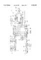
- FIG. 2is a functional block diagram of an embodiment of a multiple antenna receiver system using a single backhaul cable.
- FIGS. 3A-3Care frequency domain diagrams showing the overlap of multiple antenna signals in accordance with the embodiment of FIG. 2.
- FIG. 4is a functional block diagram of another embodiment of a multiple antenna receiver system using a single backhaul cable.
- FIG. 5is a diagram of a spread spectrum correlator as may be used in either of the embodiments shown in FIG. 2 or FIG. 4.
- FIG. 6Ais a block diagram of a delay lock tracking loop
- FIG. 6Bare waveform diagrams in accordance therewith.
- FIG. 1is a block diagram of a receiver system with multiple antennas as is known in the art.
- a transmitter 114transmits an RF signal 113 over an airwave channel via an antenna 112.
- the RF signal 113is received by a receiver system 101 comprising receiver electronics 102 and a plurality of antennas 103.
- the antennas 103are located at a distance from the receiver electronics 102.
- a separate backhaul cable 105one for each antenna 103, couples the receiver electronics 102 to each of the antennas 103.
- Each antenna 103is coupled to cable transmission electronics 106, which may comprise one or more amplifiers and filters, for converting the received signal to an IF signal or to some other format suitable for cable transmission as is known in the art. In these applications it may be necessary to convert the signal back to a format suitable for use by the receiver.
- An output of the cable transmission electronics 106is coupled to one of the backhaul cables 105.
- Each backhaul cable 105is coupled to a port 107 located at the receiver electronics 102.
- FIG. 2is a functional block diagram of a multiple antenna receiver system using a single backhaul cable in accordance with one or more principles of the present invention. Although the FIG. 2 embodiment is shown for convenience with two antennas, the described techniques are readily adaptable to an arbitrary number of antennas as required by a particular application.
- the RF signal 113is preferably a spread spectrum signal.
- a spread spectrum signalis characterized by, among other things, a bandwidth exceeding the minimum bandwidth necessary to transmit the data.
- a data signalmay be modulated with a pseudo-random code which causes the modulated signal to have a Gaussian distribution and to appear noise-like to those not knowing the particular code used to spread the data signal.
- the modulated signalmay be despread by correlating the received signal with a locally generated version of the spread spectrum code.
- Spread spectrum communication techniquesare further described in, e.g., Robert M. Dixon, Spread Spectrum Systems with Commercial Applications (John Wiley & Sons, 3d ed. 1994).
- the receiver system 120 of FIG. 2comprises at least two antennas 130 and 131 which are spatially separated.
- a plurality of antenna signals 140, 141are generated by the antennas 130, 131, respectively. Because the antennas 130, 131 are spatially separated, they may experience different fading effects and path losses.
- the antenna signals 140, 141may therefore differ in amplitude and phase, and may also experience slight deviations in frequency.
- one of the antenna signals 140 or 141is generally provided a predetermined frequency offset or displacement from the other, and the signals are then combined for transmission over a cable 152.
- the combined signalis split, and an inverse frequency offset applied to one branch of the split signal in order to remove the frequency offset from that branch.
- the receiversimultaneously receives both antenna signals 140 or 141, and each of the antenna signals 140, 141 is overlaid with the other separated by the predetermined frequency offset.
- the predetermined frequency offsetis selected as large enough so that the signals are sufficiently isolated from one another, but smaller than the full bandwidth of the received signal.
- the frequency offset +F 0is preferably kept as small as possible but large enough to maintain signal isolation with the other antenna signal 140, and its selection is described in more detail further herein.
- the antenna signal 140 and the output of the mixer 150are combined by a summer 151.
- the combined signal (also called a backhaul signal herein) output from the summer 151is transmitted along the backhaul cable 152.
- the backhaul signalPrior to transmission over the cable 152, the backhaul signal is preferably downconverted to an intermediate frequency or a baseband frequency, using one or more complementary arithmetic operation as mixer 150.
- mixer 161generates an output signal having a frequency of F 1 -F 0 for signal inputs having frequencies of F 0 and F 1 , respectively.
- Mixer 161may be viewed as providing a frequency offset of -F 0 to signal 167.
- the output of the mixer 161is a frequency shifted signal 165, which is coupled to a port 163 of the base station 164.
- each of the ports 162, 163comprises a filter 170, 171, respectively, which may remove noise associated with transmission over the cable 152.
- Signals 165 and 166are thereby filtered and, if desired and not already done, converted to baseband signals.
- the outputs from the filters 170, 171are provided to spread spectrum correlators 172, 173, respectively, mixers, filters, amplifiers or other electronics and reconverted to a suitable IF at the receiver end (not shown).
- the backhaul signalmay be made suitable for transmission over a coaxial cable, fiber optic cable, or other type of transmission media using techniques known in the art.
- circuitry for converting the antenna signals 140, 141 to an intermediate frequency or a baseband frequencymay be located further upstream at each antenna, at the expense of additional or possibly duplicative hardware.
- the combined signalis split by a signal splitter 160 into two identical signals 166, 167.
- Signal 166is input to a port 162 of receiver 164 (e.g., a base station) for further processing.
- Signal 167is input to mixer 161.
- a signale.g., a sine wave
- F 0that is, the same frequency F 0 input to mixer 150
- Mixer 161is preferably a single sideband mixer, but performs the for correlating and despreading the filtered signals.
- the outputs of the correlators 172, 173may be analyzed by the base station 164 to determine the quality of each (e.g., by determining the signal-to-noise ratio), and one of the two outputs from correlators 172, 173 may be selected for communication by techniques further described herein.
- FIGS. 3A-3Care frequency domain diagrams showing the overlap of multiple antenna signals.
- FIG. 3Ais a diagram showing a received signal S centered at a frequency F 1 representing a signal as it appears at antenna 130 or 131.
- the signals appearing at antennas 130 and 131may differ in amplitude, phase, and slight amounts of frequency due to interference, multipath fading, and similar effects.
- signal S shown in FIG. 3Ais assumed to represent both signals 140 and 141 received at antennas 130 and 131, respectively.
- FIGS. 3B and 3Crepresent signals 166 and 165, respectively, as they appear at ports 162 and 163. As shown, each of signals 166 and 165 have components of both signals 140 and 141 received at antennas 130, 131.
- FIGS. 3B and 3Cit is assumed for sake of explanation that there has been no downconversion of the backhaul signal prior to transmission over the cable 152. However, if there is downconversion of the backhaul signal, the frequency F 0 appearing in FIGS. 3B and 3C could be viewed as the intermediate or baseband frequency to which the backhaul signal has been translated.
- FIG. 3Bis a diagram showing the signals 140 and 141 as they appear at the first port 162 after being combined by summer 151 and transmitted over the cable 152.
- Signal 140 originating from the first antenna 130is centered at the original center frequency F 1 as shown and is unaffected by either mixer 150 or mixer 161.
- Signal 141 originating from the second antenna 131is shown as it appears at port 162 after addition of a frequency offset +F 0 from mixer 150, and is centered at a frequency of F 1 +F 0 .
- port 162receives the signal 140 centered at the original center frequency F 1 along with an offset version of the signal 141 centered at a frequency of F 1 +F 0 .
- signals 140 and 141are shown having similar characteristics, it is assumed, as noted, that signals 140 and 141 may have amplitude, phase and frequency differences caused by various multipath, fading or other known or unknown factors as mentioned previously.
- the port 163also receives offset versions of antenna signals 140 and 141.
- FIG. 3Cis a diagram representing the output of the second single sideband mixer 161, and shows the same signals 140 and 141 as they appear at port 163 of the base station 164.
- Antenna signal 141 originating from antenna 131is provided a frequency offset of +F 0 by mixer 150 and an opposite frequency offset of -F 0 by mixer 161, resulting in a net frequency displacement of zero.
- antenna signal 141appears centered at the original frequency F 1 .
- Signal 140 originating from the other antenna 130is provided a frequency offset of -F 0 by mixer 161, and therefore appears centered at a frequency of F 1 -F 0 .
- port 163receives signal 141 centered at the original frequency F 1 and an offset version of signal 140 centered at a frequency of F 1 -F 0 .
- the base station 164simultaneously receives both signals 140 and 141, only one of which is centered at the original center frequency F 1 at either of the different ports 162, 163.
- the base station 164may demodulate the antenna signals 140, 141, if desired, before filtering them using filters 170, 171.
- the signals 140 and 141are despread and correlated by correlators 172, 173, using an appropriate spread spectrum reference code, and using techniques known in the art for recovering data modulated in the transmitted signal. Antenna signals 140, 141 are thereby decoupled for further processing. Suitable techniques for correlation and for recovering data from a spread spectrum signal are described, for example, in the following patents and co-pending applications, each of which is incorporated by reference as if fully set forth herein:
- FIG. 5An example of a correlator that may be used in the FIG. embodiment is shown in FIG. 5.
- an input spread spectrum signal 511e.g. either of signals 165 or 166, may be provided to a correlator 501.
- the correlator 501comprises a count control 530 coupled to a code clock generator 531, which is connected to a code generator 532 and reference registers 533.
- the code generator 532is also connected to the reference registers 533.
- a code selection circuit 534is coupled to code generator 532.
- the count control 530controls the length of the particular pseudo-noise signal (i.e., spread spectrum code) chosen by code selection circuit 534 to be detected by the receiver, and outputs signals to the code clock generator 531 which causes the code generator 532 to output a code of length L to first reference registers 533.
- Count control 530triggers code clock generator 531 which thereby triggers code generator 532 and first reference registers 533.
- Code generator 532outputs the particular pseudo-noise signal to first reference registers 533 as determined by a code selection circuit 534.
- the code selection circuit 534can provide signals to the code generator 532 which enable it to scan through a plurality of pseudo noise codes. In operation, a single code can be loaded into the first reference registers 533 or, in a scanning mode, the first reference registers 533 can be periodically loaded with constantly varying codes until a match to a received code occurs.
- the input signal 511is coupled to an amplifier circuit 535, which may comprise one or more RF or IF amplifiers depending on the characteristics of the input signal 511.
- the amplifier circuit 535is coupled to a product detector 536, which is coupled to a local oscillator 537 and a low pass filter 538.
- the low pass filter 538is coupled to receive registers 539 and clock recovery circuit 546.
- the first reference registers 533store a first pseudo-noise signal
- the receive registers 539store the input spread spectrum signal.
- the first adders 540compare each chip of the received spread spectrum signal with each respective chip of the first pseudo-noise signal to generate a first plurality of chip-comparison signals.
- the first summer 541adds the first plurality of chip-comparison signals and thereby generates a first correlation signal.
- the comparator 542In response to the first correlation signal being greater than the upper-threshold level, the comparator 542 generates a first data-symbol signal. In response to the first correlation signal being less than the lower-threshold level, the comparator 542 generates a second data-symbol signal.
- an input spread spectrum signal 511 having a data signal modulated with a pseudo-noise signalwould be stored in receive registers 539 and the entire length, L, of a first spread spectrum code is stored in first reference registers 533.
- Each chip of the input pseudo-noise signalis modulo 2 added by each respective chip of the first reference pseudo-noise signal by first adders 540. This modulo addition of the two signals thereby generates a first plurality of chip-comparison signals which is transferred from first adders 540 to first summer 541.
- the first summer 541adds the first plurality of signals to generate a first correlation signal.
- the first symbol comparator 542 and second symbol comparator 543are coupled to the first summer 541.
- the comparators 542, 543have an upper-threshold level and a lower-threshold level.
- the first symbol comparator 542In response to the first correlation signal being greater than the upper-threshold level, the first symbol comparator 542 generates a first data-symbol-correlation signal.
- the second symbol-comparator 543In response to the first correlation signal being less than the lower-threshold level, the second symbol-comparator 543 generates a second data-symbol-correlation signal.
- Data generator 547thereby generates first or second data symbols, per the first or second data-symbol-correlation signal, respectively.
- the first and second data-symbol signalsmay be, respectively, 1-bit and 0-bit data signals.
- the correlator 501is intended to be an exemplary embodiment of a suitable correlator to be used in conjunction with the FIG. 2 embodiment of the present invention, and it is understood that a variety of other correlators will also be suitable.
- one of the antenna signals(e.g., antenna signal 140) is despread and/or correlated, using, for example, a correlator as shown in FIG. 5.
- the other antenna signal(e.g., antenna signal 141) is despread and/or correlated, using, for example, a correlator as shown in FIG. 5.
- the two signals 140 and 141should not unduly interfere with one another, and should therefore be isolated from each other, if the frequency offset F 0 is sufficiently large. It will often be the case that one of the antenna signals 140, 141 will be of better quality than the other, so that the antenna signal (for example, antenna signal 140) corresponding to the antenna with the best received signal (as measured, for example, by signal/noise ratio) will dominate the other antenna signals (for example, antenna signal 141). Because of this phenomenon, additional isolation between the two signals 140 and 141, besides that provided by the frequency offset F 0 , is provided by the inherent differences in the received signals 140 and 141.
- the frequency offset F 0is thus preferably of a predefined minimum size in order to maintain isolation between the two antenna signals 140 and 141. Within this constraint, the frequency offset F 0 should also be kept as small as possible to minimize the bandwidth requirements of the cable 152.
- the transmitted signal 113is a spread spectrum signal
- the frequency offset F 0 applied by the first mixer 150 and the second mixer 161may be as small as 1/(2xCPI) Hz, where CPI is the coherent processing interval of the spread spectrum signal 113.
- the spreading bandwidthis 10 MHz
- the CPIis 5 microseconds
- the frequency offset F 0is 100 KHz.
- the bandwidth requirement for a pure FDMA system for transmission over a single backhaul cablewould be 20 MHz, or twice the bandwidth of the transmitted signal 113.
- the bandwidth requirement for a pure FDMA systemwould be N times that of the transmitted signal 113.
- the FIG. 2 embodimentmay be employed in a spread spectrum system using an M-ary technique, wherein each data symbol is associated with a particular sequence of data bits and is represented by a unique spread spectrum code.
- each of the data bit sequences 00, 01, 10 and 11(referred to as data symbols) may be represented by a different spread spectrum code (called symbol codes).
- symbol codesa different spread spectrum code
- an input data signalmay be comprised of a plurality of data symbols, each of which results in the transmission of a corresponding symbol code.
- the minimum preferred frequency isolation of the FIG. 2 embodimentis provided by a frequency offset F 0 of 1/(2xT s ), where T s is the transmission time of a data symbol.
- Such a frequency offsetshould normally allow sufficient frequency isolation of the two received signals 140 and 141 at the ports 162, 163 of the base station 164 to enable proper despreading.
- the base station 164may measure the quality of the two signals 165, 166 and select one or more of the two signals 165, 166, thereby selecting one or more antennas 131 or 130 for receiving the RF signal 113.
- the base station 164may measure a signal/noise ratio of each signal 165, 166, and may select the one with the best signal/noise ratio.
- the base station 164may dynamically switch between signals 165 and 166, thereby switching selected antennas 131, 130, as the quality of the received signal changes over time.
- One such techniqueis known as selection diversity, in which one of a plurality of antennas is selected for communication, and is used for communication until the signal quality for that antenna deteriorates.
- the base station 164may select signal 165 (thereby selecting antenna 131) for communication, after which the base station 164 continues using antenna 131 for communication.
- the base stationmay make another selection decision based on the relative quality of the signals 165, 166.
- An advantage of using selection diversityis that only one set of demodulation and despreading hardware is needed at the base station 164. Thus, only one of the pair of filters 170, 171 and one of the pair of correlators 172, 173 is necessary if selection diversity is used.
- a switchmay be used selecting between signals 165 and 166.
- One of signals 165, 166is provided to a single filter and correlator, and the signal quality measured, after which the other one of signals 165, 166 is provided to the single filter and correlator, and the signal quality measured. The superior of the two signals 165, 166 is selected for communication thereafter until the measured signal quality deteriorates to an unacceptable level.
- combining diversityAnother known technique used in selecting among a plurality of antenna signals is known as combining diversity.
- parallel hardwareis used to demodulate and despread the signals 165, 166, and to measure signal quality.
- One or more of the signals 165, 166is dynamically selected for communication.
- a maximum likelihood estimatormay also be used in conjunction with combining diversity techniques, whereby the signals 165, 166 are weighted depending on their signal quality prior to being combined according to their weighted values.
- FIG. 2 systempreserves potentially limited bandwidth of the backhaul cable system.
- the FIG. 2 systemmay be contrasted with conventional techniques (such as shown in FIG. 1), wherein each antenna signal 110 to be transmitted over a backhaul cable 105 adds an extra full signal bandwidth requirement to the backhaul cable system.
- each antenna 103 in the conventional systemis to receive a spread spectrum signal of 10 MHz and send it to a base station over a single backhaul cable 105, then two receiving antennas would require a backhaul capacity in the cable of 20 MHz, three receiving antennas would require a capacity of 30 MHz, and so on.
- the bandwidth requirements for the backhaul cable 105increase proportionately to the number of receiving antennas, so does the cost and complexity of the antenna electronics.
- backhaul cables, and/or the electronics used for transmitting signals over backhaul cablesgenerally have a limited bandwidth capacity, e.g. 25 MHz, particularly with respect to upstream transmission of information.
- This limited capacityeffectively limits the number of antennas that may be connected to a single backhaul cable, and the number of antenna signals that may be transmitted thereover.
- Such a limitationcan be a drawback in existing systems in which expensive backhaul cables of limited bandwidth have been deployed, but where additional receiving antennas are desired but cannot be deployed due to bandwidth constraints of the existing system.
- an aspect of the present inventionas embodied, for example, in the system of FIG. 2, provides the ability to transmit multiple antenna signals over a relatively narrow bandwidth.
- This abilityallows the use of backhaul cables of limited bandwidth capacity, such as existing backhaul cables commonly used in cable TV systems, and may also require the use of fewer amplifiers and other supporting electronics to transmit antenna signals over the backhaul cable.
- the FIG. 2 embodimentis suitable for many diverse applications, including communication systems using direct sequence or frequency hopping spread spectrum communication techniques.
- the FIG. 2 embodimentmay not be optimal for use in a system using solely time division multiple access (TDMA) techniques, without the addition of spread spectrum encoding.
- TDMAtime division multiple access
- FIG. 4is a functional block diagram of another embodiment of the invention.
- the FIG. 4 embodimentmay be used in conjunction with a pure TDMA system, or a variety of other communication systems.
- FIG. 4 embodimentis shown for convenience with two antennas, the described techniques are extensible to an arbitrary number of antennas as required by a particular application.
- a receiver system 210receives an RF signal 113 from a transmitter 114, which may be one of a plurality of transmitters 114 from which the receiver system 210 may receive the RF signal 113.
- the receiving system 210 of FIG. 4comprises at least two antennas 230 and 231 which are spatially separated.
- a plurality of antenna signals 240, 241are generated by the antennas 230, 231, respectively. Because the antennas 230, 231 are spatially separated, they may experience different fading effects and path losses.
- the antenna signals 240, 241may therefore differ in amplitude and phase, and may also experience slight deviations in frequency.
- a plurality of antenna signals 240, 241are generated by the antennas 230, 231, respectively.
- the antenna signals 240, 241are code division multiplexed prior to transmission on the backhaul cable 199 using a spread spectrum transmission technique.
- each antenna signal 240, 241is modulated with a different chip code and then transmitted over a backhaul cable 199.
- the first antenna signal 240is modulated with a first chip code 193 by a modulator 180 to generate a spread spectrum signal 195.
- the second antenna signal 241is modulated with a second chip code 194, distinct from the first chip code 193, by another modulator 181 to generate another spread spectrum signal 196.
- the modulators 180 and 181may each comprise a modulo-2 adder or an exclusive-OR gate.
- the spread spectrum signals 195 and 196are combined by a summer 182.
- An output of the summer 182is a combined signal (also called a backhaul signal herein), which is transmitted along the backhaul cable 199.
- the backhaul signalessentially comprises two overlaid signals, which are antenna signal 240 modulated by the first spread spectrum code 193, and antenna signal 241 modulated by the second spread spectrum code 194.
- the backhaul signalPrior to transmission over the cable 199, the backhaul signal is preferably downconverted to an intermediate frequency or a baseband frequency, using one or more mixers, filters, amplifiers or other electronics and reconverted to a suitable IF at the receiver end (not shown).
- the backhaul signalmay be made suitable for transmission over a coaxial cable, fiber optic cable, or other type of transmission media using methods known in the art.
- circuitry for converting the antenna signals 140, 141 to an intermediate frequency or a baseband frequencymay be located further upstream at each antenna, at the expense of additional or possibly duplicative hardware.
- the combined signalis split by a splitter 183 into two duplicate signals 184, 185.
- One duplicate signal 184is despread and correlated with the first spread spectrum signal 193 by a correlator 186.
- the other duplicate signal 185is despread and correlated with the second spread spectrum code 194 by another correlator 187.
- Each of correlators 186, 187may comprise a correlator such as shown in FIG. 5, or any of the patents and copending applications previously incorporated herein.
- An output 188 of correlator 186is coupled to a port 190 of a receiver 192 (e.g., a base station).
- An output 189 of the other correlator 187is coupled to another port 191 of the base station 192.
- the output of correlator 186is essentially a recovered version of the first antenna signal 240
- the output of correlator 187is essentially a recovered version of the second antenna signal 241.
- Correlator 186receives from the cable 199 the backhaul signal which, as noted, comprises the first antenna signal 240 modulated by the first spread spectrum code 193, and the second antenna signal 241 modulated by the second spread spectrum code 194. Correlator 186 correlates the backhaul signal with the first spread spectrum code 193, and in doing so recovers the first antenna signal 240 encoded with the same spread spectrum code 193. However, correlator 186 rejects the second antenna signal 241, which has been encoded with the second spread spectrum code 194. The correlator 186 thereby essentially converts the second antenna signal 241 into noise, as the product of two distinct chip codes (such as the first chip code 193 and second chip code 194) generally creates a signal having a noise-like distribution.
- Correlator 187operates on the same principle for recovering the second antenna signal 241 while rejecting the first antenna signal 240. By operation of correlators 186 and 187, antenna signals 240 and 241 are thereby decoupled from one another.
- Outputs from each of correlators 186 and 187are coupled to different ports 188, 189 of the base station 192.
- the base station 192simultaneously receives a recovered version of the first antenna signal 240 at the first port 188 and a recovered version of the second antenna signal 241 at the second port 189.
- the correlators 186, 187may embody correlation techniques such as described in U.S. Pat. No. 5,016,255, U.S. Pat. No. 5,022,047, or described herein with respect to FIG. 5, or as described in any of the patent applications previously incorporated by reference.
- the precise correlation method selecteddepends in part on hardware constraints and the particular spread spectrum encoding scheme employed by modulators 180, 181.
- Correlationmay be either serial or parallel, either coherent or non-coherent, and may utilize synchronization and tracking techniques (if necessary) as described in the previously referenced patents and patent applications, or as otherwise known in the art.
- the FIG. 4 embodimentmay use a delay lock tracking loop 601 such as shown in FIG. 6A for maintaining synchronization between modulators 180, 181 and correlators 186, 187.
- the problem addressed by a delay lock tracking loopmay be described as follows. Although an identical version of spread spectrum code 193 may be generated locally at both modulator 180 and correlator 186, the local versions of spread spectrum code 193 may be delayed in time from one another. Likewise, although an identical version of spread spectrum code 194 may be generated locally at both modulator 181 and correlator 187, the local versions of spread spectrum code 194 may be delayed in time from one another. Assuming initial synchronization has already been accomplished (e.g., by using a sliding coincidence correlator or similar means), the amount of delay between the local versions of the spread spectrum codes 193, 194 is usually one or two chips.
- a register 630stores all or a portion of a locally generated version of a spread spectrum code, such as spread spectrum code 193 or 194.
- Local reference signal 605is derived from the last chip (i.e., the Nth chip) stored in register 630, while local reference signal 606 is derived from the next to last chip (i.e., the (N-1)th chip) stored in register 630.
- Local reference signals 605 and 606are thereby delayed by one chip time from one another.
- Local reference signal 605is correlated with the input signal 604, such as signal 184 or 185, using correlator 607.
- Local reference signal 606is correlated with the input signal 604 using correlator 608.
- the output 609 of correlator 607will ordinarily be a triangular function two chips wide.
- the output 610 of the correlator 608will ordinarily be a triangular function two chips wide, but offset in time with respect to output 609 by the amount of delay between the Nth chip and the (N-1)th chip.
- the output 609 of correlator 607is coupled to an envelope detector 611.
- the output 610 of correlator 608is coupled to another envelope detector 612.
- An output from each of the envelope detectors 611, 612is coupled to an input of a comparator 615, which generates a composite correlation output 616.
- the composite correlation output 616as shown in FIG. 6B, has a double-peaked triangular shape, in which one-half of the double triangle is inverted, so that the composite correlation has a linear region centered around the point halfway between the two correlation maxima.
- the composite correlation output 616is coupled to a loop filter 620 and used to control a clock source 621, such as a voltage controlled oscillator (VCO).
- the clock source 621is coupled to a clock network 622, which provides a code clock signal 623 for clocking the locally generated spread spectrum code.
- the delay lock tracking loop 601thereby causes the local reference signals 605, 606 to track the incoming signal 604 at a point halfway between the maximum and the minimum of the composite correlation output 616.
- an auto-synchronous correlatorsuch as described in U.S. patent application Ser. No. 08/146,491 now abandoned referenced previously herein, may be used for each of correlators 186, 187, eliminating at least some of the additional overhead for maintaining synchronization.
- each antenna signal 240, 241is spread spectrum encoded using a code sequence that is a Walsh function.
- Walsh function code sequences for spread spectrum encodingare known in the art.
- Orthogonal Walsh functionsare selected for each antenna signal 240, 241; thus, spread spectrum code 193 comprises a first Walsh function, and spread spectrum code 194 comprises a second Walsh function orthagonal to the first Walsh function.
- the spread spectrum encoded signals 195, 196are, after being combined and transmitted over the cable 199, despread using the same orthogonal Walsh functions 193, 194, respectively.
- the orthogonal Walsh functionsprovide sufficient isolation between antenna signals 240, 241 so that frequency isolation such as described with respect to FIGS. 2 and 3A-3C is generally unnecessary.
- one of the Walsh functions 193, 194is a sequence of all 1's. Use of such a Walsh function essentially eliminates the need for one branch of hardware.
- the second modulator 181 and second correlator 187could be eliminated in this embodiment, and the first spread spectrum code 193 would preferably be selected so as to be orthagonal with a sequence of all 1's.
- the required isolation between the spread spectrum signals 195, 196is generally low. This is so because a frequency separation for spread spectrum signals does not generally have to be large in comparison with the bandwidth of the spread spectrum signals.
- the frequency offset chosenshould be sufficient to cause lack of correlation of each spread spectrum signal 195, 196 by a correlator matched to the other spread spectrum signal.
- the level of interference between the two overlaid spread spectrum signalsis in many cases reduced because one of the two antenna signals 240, 241 will dominate the other at least to some degree over periods of time, reducing the need for additional isolation.
- first and second modulators 180, 181may be employed at the first and second modulators 180, 181.
- the first and second correlators 186, 187may comprise corresponding hardware as conventionally used in the art for despreading and decoding the backhaul signal.
- the ports 188, 189may each comprise a filter 200, 201, respectively, and, if a spread spectrum signal is being received, a despreading and/or correlating circuit 202, 203, respectively.
- Despreading/correlating circuits 202, 203may each comprise a correlator such as described in the previously cited patents and patent applications, or for example as shown in FIG. 5.
- the signal received at antennas 230, 231need not be a spread spectrum signal, and thus each of the ports 188, 189 may comprise appropriate hardware for demodulating the particular type of signals sent.
- the base station 192may thereafter select one or more of the signals 188, 189 for communication, and thereby select one or more of the antennas 230, 231 based on the relative quality of the signals 188, 189, in a manner similar to that described with respect to the FIG. 2 embodiment.
- the base station 192may utilize selection diversity, combining diversity, or any other type of antenna selection method as known in the art.
- the present inventionmay be used in polarization diversity.
- polarization diversitya single antenna may have a vertical polarization signal and a horizontal polarization signal requiring transmission to a receiver.
- To deliver both the vertical and the horizontal polarization signalsnormally requires the ability to send a signal having twice the bandwidth as the received signal.
- the vertical and horizontal polarization signalslike diverse antenna signals 140 and 141, may be combined for transmission along a single cable.
- time division multiplexingmay be used to increase the throughput over a backhaul cable 152 (or 199).
- time division multiplexinga defined time period is divided into a plurality of time frames, and each time frame is further divided into a plurality of time slots.
- Each antenna signal 140, 141(or 240, 241) may be periodically sampled using A/D sampling at a rate corresponding to at least twice the bandwidth of the received signal.
- Each time slot of a time framemay be assigned specific antenna and used for transmission of the data sampled from that antenna. Generally, each antenna would be serviced in at least one time slot in each time frame.
Landscapes
- Engineering & Computer Science (AREA)
- Computer Networks & Wireless Communication (AREA)
- Signal Processing (AREA)
- Mobile Radio Communication Systems (AREA)
- Radio Transmission System (AREA)
Abstract
Description
Claims (21)
Priority Applications (9)
| Application Number | Priority Date | Filing Date | Title |
|---|---|---|---|
| US08/334,587US5742583A (en) | 1994-11-03 | 1994-11-03 | Antenna diversity techniques |
| PCT/US1995/013170WO1996014699A1 (en) | 1994-11-03 | 1995-10-12 | Antenna diversity techniques |
| IL11559395AIL115593A (en) | 1994-11-03 | 1995-10-12 | Reveiver comprising diverse antennas |
| EP95939516AEP0789957A4 (en) | 1994-11-03 | 1995-10-12 | Antenna diversity techniques |
| KR1019970702976AKR970707659A (en) | 1994-11-03 | 1995-10-12 | Antenna Diversity Techniques |
| JP8515316AJPH10509848A (en) | 1994-11-03 | 1995-10-12 | Antenna diversity technology |
| CA002204376ACA2204376A1 (en) | 1994-11-03 | 1995-10-12 | Antenna diversity techniques |
| US08/555,117US5859842A (en) | 1994-11-03 | 1995-11-08 | Antenna diversity techniques |
| US09/109,502US6522642B1 (en) | 1994-11-03 | 1998-07-02 | Antenna diversity techniques |
Applications Claiming Priority (1)
| Application Number | Priority Date | Filing Date | Title |
|---|---|---|---|
| US08/334,587US5742583A (en) | 1994-11-03 | 1994-11-03 | Antenna diversity techniques |
Related Child Applications (1)
| Application Number | Title | Priority Date | Filing Date |
|---|---|---|---|
| US08/555,117ContinuationUS5859842A (en) | 1994-11-03 | 1995-11-08 | Antenna diversity techniques |
Publications (1)
| Publication Number | Publication Date |
|---|---|
| US5742583Atrue US5742583A (en) | 1998-04-21 |
Family
ID=23307895
Family Applications (3)
| Application Number | Title | Priority Date | Filing Date |
|---|---|---|---|
| US08/334,587Expired - LifetimeUS5742583A (en) | 1994-11-03 | 1994-11-03 | Antenna diversity techniques |
| US08/555,117Expired - Fee RelatedUS5859842A (en) | 1994-11-03 | 1995-11-08 | Antenna diversity techniques |
| US09/109,502Expired - LifetimeUS6522642B1 (en) | 1994-11-03 | 1998-07-02 | Antenna diversity techniques |
Family Applications After (2)
| Application Number | Title | Priority Date | Filing Date |
|---|---|---|---|
| US08/555,117Expired - Fee RelatedUS5859842A (en) | 1994-11-03 | 1995-11-08 | Antenna diversity techniques |
| US09/109,502Expired - LifetimeUS6522642B1 (en) | 1994-11-03 | 1998-07-02 | Antenna diversity techniques |
Country Status (7)
| Country | Link |
|---|---|
| US (3) | US5742583A (en) |
| EP (1) | EP0789957A4 (en) |
| JP (1) | JPH10509848A (en) |
| KR (1) | KR970707659A (en) |
| CA (1) | CA2204376A1 (en) |
| IL (1) | IL115593A (en) |
| WO (1) | WO1996014699A1 (en) |
Cited By (23)
| Publication number | Priority date | Publication date | Assignee | Title |
|---|---|---|---|---|
| US5844632A (en)* | 1994-10-04 | 1998-12-01 | Matsushita Electric Industrial Co., Ltd. | Diversity receiving apparatus for a mobile unit |
| US6128276A (en)* | 1997-02-24 | 2000-10-03 | Radix Wireless, Inc. | Stacked-carrier discrete multiple tone communication technology and combinations with code nulling, interference cancellation, retrodirective communication and adaptive antenna arrays |
| US6272121B1 (en)* | 1997-03-03 | 2001-08-07 | Omnipoint Corporation | Spread spectrum communication system using DECT protocol |
| GB2371716A (en)* | 2001-01-29 | 2002-07-31 | Ubinetics Ltd | A radio receiver and method of searching or acquiring signals |
| US20020164963A1 (en)* | 2001-04-09 | 2002-11-07 | Tehrani Ardavan Maleki | Method and system for providing antenna diversity |
| US20030002604A1 (en)* | 2001-06-27 | 2003-01-02 | Koninklijke Philips Electronics N.V. | Frequency offset diversity receiver |
| US6522642B1 (en)* | 1994-11-03 | 2003-02-18 | Intel Corporation | Antenna diversity techniques |
| US20030112851A1 (en)* | 2001-12-14 | 2003-06-19 | International Business Machines Corporation | Dynamic measurement of communication channel characteristics using direct sequence spread spectrum (DSSS) systems, methods and program products |
| US20030190153A1 (en)* | 2000-09-18 | 2003-10-09 | Masanori Itoh | Voice/video information recording/reproducing device and method therefor |
| EP0969611A3 (en)* | 1998-07-01 | 2003-11-05 | Radio Frequency Systems Inc. | Apparatus for communicating diversity signals over a transmission medium |
| US20040114693A1 (en)* | 2002-12-17 | 2004-06-17 | Juinn-Horng Deng | Apparatus and method for estimation of frequency offset in wireless communications |
| US20050259027A1 (en)* | 2004-05-19 | 2005-11-24 | Haim Grebel | Independently center fed dipole array |
| US20060017633A1 (en)* | 2002-12-04 | 2006-01-26 | Koninklijke Philips Electronics N.V. | Method and apparatus for true diversity reception with single antenna |
| US7054397B1 (en)* | 1999-02-05 | 2006-05-30 | Nec Corporation | Mobile communication system having mobile stations and a base station |
| US20060194575A1 (en)* | 2003-08-19 | 2006-08-31 | Sony Deutschland Gmbh | RF coverage extension for wireless home networking systems |
| US20070173288A1 (en)* | 2006-01-25 | 2007-07-26 | Telefonaktiebolaget Lm Ericsson (Publ) | Method and apparatus for reducing combiner loss in a multi-sector, omni-base station |
| US20070191064A1 (en)* | 2004-03-11 | 2007-08-16 | Telefonaktiebolaget Lm Ericsson (Publ) | Method device base station and site for reducing the number of feeders in an antenna diversity diversity system |
| RU2342784C2 (en)* | 2004-06-15 | 2008-12-27 | Телефонактиеболагет Лм Эрикссон (Пабл) | Device and expedient of spatial diversity of antennas |
| US10924825B2 (en) | 2018-04-16 | 2021-02-16 | Charter Communications Operating, Llc | Apparatus and methods for enhancing quality of experience for over-the-top data services over high-capacity wireless networks |
| US11129213B2 (en) | 2018-10-12 | 2021-09-21 | Charter Communications Operating, Llc | Apparatus and methods for cell identification in wireless networks |
| US11985641B2 (en) | 2020-04-22 | 2024-05-14 | Charter Communications Operating, Llc | Node apparatus and methods for providing high-capacity data services via a content delivery network architecture |
| US12149373B2 (en) | 2020-04-22 | 2024-11-19 | Charter Communications Operating, Llc | Premises apparatus and methods for aggregated high-capacity data services |
| US12200814B2 (en) | 2018-08-07 | 2025-01-14 | Charter Communications Operating, Llc | Apparatus and methods for registration and operation in wireless networks |
Families Citing this family (44)
| Publication number | Priority date | Publication date | Assignee | Title |
|---|---|---|---|---|
| US6201801B1 (en)* | 1994-03-24 | 2001-03-13 | Ericsson Inc. | Polarization diversity phased array cellular base station and associated methods |
| GB2310109B (en)* | 1996-02-08 | 2000-07-05 | Orange Personal Comm Serv Ltd | Antenna arrangement |
| GB2354413B (en)* | 1996-07-23 | 2001-05-30 | Roke Manor Research | Randomised code acquisition |
| US7133380B1 (en)* | 2000-01-11 | 2006-11-07 | At&T Corp. | System and method for selecting a transmission channel in a wireless communication system that includes an adaptive array |
| JP3134814B2 (en)* | 1997-06-26 | 2001-02-13 | 日本電気株式会社 | Diversity reception method |
| JP3967452B2 (en)* | 1998-03-13 | 2007-08-29 | 株式会社東芝 | Spread spectrum wireless transmission receiver |
| JP3406831B2 (en)* | 1998-03-19 | 2003-05-19 | 富士通株式会社 | Array antenna system for wireless base station |
| DE59904748D1 (en)* | 1998-06-29 | 2003-04-30 | Siemens Ag | TRANSMISSION OF DATA BY ULTRASOUND |
| US6128330A (en) | 1998-11-24 | 2000-10-03 | Linex Technology, Inc. | Efficient shadow reduction antenna system for spread spectrum |
| US6298227B1 (en)* | 1998-12-22 | 2001-10-02 | Ericsson Inc. | Method and apparatus for frequency conversion for a receiver with a limited-accuracy oscillator |
| US6505037B1 (en)* | 1999-06-29 | 2003-01-07 | Sharp Laboratories Of America, Inc. | Data unit detection including antenna diversity |
| WO2001063779A2 (en)* | 2000-02-24 | 2001-08-30 | Tantivy Communications, Inc. | Method and system for economical beam forming in a radio communication system |
| WO2001069824A1 (en)* | 2000-03-14 | 2001-09-20 | Vyyo, Ltd. | Low-complexity beam forming and antenna diversity receiver |
| US7184724B1 (en)* | 2000-04-18 | 2007-02-27 | Microtune (Texas), L.P. | System and method for frequency translation using an image reject mixer |
| JP3808280B2 (en)* | 2000-04-28 | 2006-08-09 | 富士通株式会社 | Synchronization establishment device, synchronization establishment method, and receiver |
| FR2812143B1 (en)* | 2000-07-21 | 2003-08-29 | Sagem | SPATIAL DIVERSITY POSITIONING DEVICE USING RADIO SIGNALS FROM SATELLITES |
| US7171223B2 (en)* | 2003-01-10 | 2007-01-30 | Belair Networks, Inc. | Automatic antenna selection for mesh backhaul network nodes |
| CN1799236B (en)* | 2003-03-28 | 2010-12-08 | 北方电讯网络有限公司 | Method and apparatus for processing multiple common frequency signals through a single cable by circulator |
| US7782827B2 (en) | 2003-03-28 | 2010-08-24 | Nortel Networks Limited | Method and apparatus for processing multiple common frequency signals through a single cable using circulators |
| US7424039B2 (en)* | 2003-03-28 | 2008-09-09 | Nortel Networks Limited | Method and apparatus for processing multiple common frequency signals through a single cable |
| WO2004098104A1 (en)* | 2003-04-25 | 2004-11-11 | Cingular Wireless | Systems and methods for implementing fully redundant antenna hopping with multi-carrier power amplifiers and combining schemes within a base station |
| US7729726B2 (en)* | 2004-03-26 | 2010-06-01 | Nortel Networks Limited | Feeder cable reduction |
| GB0415811D0 (en)* | 2004-07-15 | 2004-08-18 | Quintel Technology Ltd | Antenna system for shared operation |
| US7907910B2 (en)* | 2004-08-02 | 2011-03-15 | Intel Corporation | Method and apparatus to vary power level of training signal |
| US8135086B1 (en) | 2004-08-09 | 2012-03-13 | Rockstar Bidco, LP | Cable reduction |
| DE102004062000A1 (en)* | 2004-12-23 | 2006-07-06 | Robert Bosch Gmbh | Antenna diversity unit |
| US7546146B2 (en)* | 2005-02-01 | 2009-06-09 | Gm Global Technology Operations, Inc. | Control system and method for diversity antenna system |
| US7251455B1 (en)* | 2005-07-11 | 2007-07-31 | L-3 Communications Corporation | Techniques for antenna tracking |
| AU2006293084B2 (en)* | 2005-09-22 | 2009-10-29 | Olympus Corporation | Receiver |
| US8452333B2 (en)* | 2005-12-12 | 2013-05-28 | Apple Inc. | Feeder cable reduction |
| US7792548B2 (en)* | 2006-09-28 | 2010-09-07 | Broadcom Corporation | Multiple frequency antenna array for use with an RF transmitter or transceiver |
| US20080304831A1 (en)* | 2007-06-08 | 2008-12-11 | Miller Ii Robert Raymond | Mesh free-space optical system for wireless local area network backhaul |
| DE102007061739A1 (en)* | 2007-12-20 | 2009-06-25 | Robert Bosch Gmbh | Method for improving the reception and reception system |
| US8537745B2 (en)* | 2008-06-02 | 2013-09-17 | Qualcomm Incorporated | Multiplexing arrangements for multiple receive antennas |
| JP5367741B2 (en)* | 2011-02-18 | 2013-12-11 | テレフオンアクチーボラゲット エル エム エリクソン(パブル) | Method, apparatus, base station, and base station site for reducing the number of feeders in an antenna diversity system |
| JP5868749B2 (en)* | 2012-03-22 | 2016-02-24 | 株式会社日立国際電気 | Communications system |
| CN103841666B (en)* | 2012-11-21 | 2018-09-07 | 华为技术有限公司 | The method of base station and its signal return, equipment |
| US8989784B2 (en)* | 2012-11-29 | 2015-03-24 | Intel Mobile Communications GmbH | Radio communication devices and methods for controlling a radio communication device |
| US9960827B2 (en)* | 2016-04-14 | 2018-05-01 | Raytheon Company | Analog multiple beam feed systems and methods |
| US10263684B2 (en)* | 2016-07-16 | 2019-04-16 | Phazr, Inc. | Wireless system using different bands in the transmit and receive direction and applying frequency shifts for bandwidth expansion |
| US20180091213A1 (en)* | 2016-09-27 | 2018-03-29 | Nokia Solutions And Networks Oy | Mobile base station receiver digitalization capacity enhancement using combined analog signals |
| CN109450502A (en)* | 2018-12-19 | 2019-03-08 | 北京唯得科技有限公司 | Single cable MIMO signal transmitting device and transmission method |
| US10693529B1 (en)* | 2019-09-30 | 2020-06-23 | Aeroantenna Technology, Inc. | Method and apparatus for multiplexing several antenna subsystem signals onto a single RF coaxial cable |
| US11942982B2 (en) | 2022-01-11 | 2024-03-26 | L3Harris Technologies, Inc. | Tactical/legacy waveform obfuscation through independent spreading overlay |
Citations (29)
| Publication number | Priority date | Publication date | Assignee | Title |
|---|---|---|---|---|
| US4301530A (en)* | 1978-12-18 | 1981-11-17 | The United States Of America As Represented By The Secretary Of The Army | Orthogonal spread spectrum time division multiple accessing mobile subscriber access system |
| US4324001A (en)* | 1980-08-15 | 1982-04-06 | Communications Satellite Corporation | Synchronizer for MSK burst communications |
| US4327438A (en)* | 1978-12-19 | 1982-04-27 | Siemens Aktiengesellschaft | Receiving circuit in an interference-suppressing communications system comprising narrow-band conventional message modulation and additional pseudo-noise phase shift keying |
| US4338579A (en)* | 1980-07-30 | 1982-07-06 | Communications Satelite Corp. | Frequency shift offset quadrature modulation and demodulation |
| US4423519A (en)* | 1982-01-20 | 1983-12-27 | Sperry Corporation | Apparatus and method for detecting the onset of a frequency shift keyed signal |
| US4563774A (en)* | 1982-10-25 | 1986-01-07 | At&T Bell Laboratories | Address coded communication system |
| US4630283A (en)* | 1985-07-17 | 1986-12-16 | Rca Corporation | Fast acquisition burst mode spread spectrum communications system with pilot carrier |
| US4649549A (en)* | 1983-08-30 | 1987-03-10 | Sophisticated Signals And Circuits | Apparatus for synchronizing linear PN sequences |
| US4688210A (en)* | 1985-03-29 | 1987-08-18 | U.S. Philips Corporation | Method of and arrangement for synchronizing the receiver arrangements in a digital multiplex transmission system |
| US4724435A (en)* | 1985-11-06 | 1988-02-09 | Applied Spectrum Technologies, Inc. | Bi-directional data telemetry system |
| US4759078A (en)* | 1986-11-14 | 1988-07-19 | Rose Communication Systems, Inc. | Coordinated local oscillator receiving system |
| US4759034A (en)* | 1986-12-02 | 1988-07-19 | General Research Of Electronics, Inc. | Multi-step spread spectrum communication apparatus |
| US4797947A (en)* | 1987-05-01 | 1989-01-10 | Motorola, Inc. | Microcellular communications system using macrodiversity |
| US4807222A (en)* | 1986-08-25 | 1989-02-21 | American Telephone And Telegraph Company At&T Bell Laboratories | Cordless accessed high-speed high-capacity local area networks |
| EP0361299A2 (en)* | 1988-09-29 | 1990-04-04 | Ascom Zelcom Ag | Digital radio transmission system for a cellular network using the spread spectrum technique |
| US5029184A (en)* | 1990-01-24 | 1991-07-02 | Harris Corporation | Low probability of intercept communication system |
| US5097484A (en)* | 1988-10-12 | 1992-03-17 | Sumitomo Electric Industries, Ltd. | Diversity transmission and reception method and equipment |
| US5103459A (en)* | 1990-06-25 | 1992-04-07 | Qualcomm Incorporated | System and method for generating signal waveforms in a cdma cellular telephone system |
| US5146471A (en)* | 1989-03-23 | 1992-09-08 | Echelon Systems Corporation | Correlator for spread spectrum communications systems |
| US5241690A (en)* | 1990-06-21 | 1993-08-31 | Telefonaktiebolaget L M Ericsson | Method for regulating power in a digital mobile telephony system |
| US5280472A (en)* | 1990-12-07 | 1994-01-18 | Qualcomm Incorporated | CDMA microcellular telephone system and distributed antenna system therefor |
| WO1995003652A1 (en)* | 1993-07-20 | 1995-02-02 | Qualcomm Incorporated | Walsh sequence generation for variable data rates |
| US5392459A (en)* | 1991-11-27 | 1995-02-21 | Nec Corporation | Power control in microwave transmission system increasing power of both horizontally and vertically polarized waves |
| WO1995006365A1 (en)* | 1993-08-27 | 1995-03-02 | Qualcomm Incorporated | Dual distributed antenna system |
| US5410568A (en)* | 1992-01-13 | 1995-04-25 | Interdigital Technology Corporation | CDMA/TDMA spread-spectrum communications system and method |
| WO1995012296A1 (en)* | 1993-10-28 | 1995-05-04 | Qualcomm Incorporated | Method and apparatus for performing handoff between sectors of a common base station |
| US5414728A (en)* | 1993-11-01 | 1995-05-09 | Qualcomm Incorporated | Method and apparatus for bifurcating signal transmission over in-phase and quadrature phase spread spectrum communication channels |
| WO1995012938A1 (en)* | 1993-11-01 | 1995-05-11 | Qualcomm Incorporated | Variable rate signal transmission in a spread spectrum communication system using coset coding |
| WO1995012943A1 (en)* | 1993-11-01 | 1995-05-11 | Qualcomm Incorporated | Method and apparatus for the transmission of variable rate digital data |
Family Cites Families (90)
| Publication number | Priority date | Publication date | Assignee | Title |
|---|---|---|---|---|
| US4285060A (en)* | 1978-02-28 | 1981-08-18 | Harris Corporation | Spread spectrum code tracking loop |
| US4189677A (en)* | 1978-03-13 | 1980-02-19 | Purdue Research Foundation | Demodulator unit for spread spectrum apparatus utilized in a cellular mobile communication system |
| US4222115A (en)* | 1978-03-13 | 1980-09-09 | Purdue Research Foundation | Spread spectrum apparatus for cellular mobile communication systems |
| JPS55157321U (en)* | 1979-04-02 | 1980-11-12 | ||
| US4291410A (en)* | 1979-10-24 | 1981-09-22 | Rockwell International Corporation | Multipath diversity spread spectrum receiver |
| CA1166699A (en)* | 1980-01-28 | 1984-05-01 | Haruo Shiki | Space-diversity board-band digital radio receiver with amplitude dispersion detecting and suppressing means |
| US4455651A (en)* | 1980-10-20 | 1984-06-19 | Equatorial Communications Company | Satellite communications system and apparatus |
| US4418425A (en)* | 1981-08-31 | 1983-11-29 | Ibm Corporation | Encryption using destination addresses in a TDMA satellite communications network |
| DE3377886D1 (en)* | 1982-03-10 | 1988-10-06 | Emi Ltd | Improvements relating to communication over noisy lines |
| CA1191905A (en)* | 1982-06-30 | 1985-08-13 | Canadian Patents And Development Limited/Societe Canadienne Des Brevets Et D'exploitation Limitee | Spread spectrum modem |
| DE3302828A1 (en)* | 1983-01-28 | 1984-08-02 | Standard Elektrik Lorenz Ag, 7000 Stuttgart | RECEIVER |
| US4550414A (en)* | 1983-04-12 | 1985-10-29 | Charles Stark Draper Laboratory, Inc. | Spread spectrum adaptive code tracker |
| FR2549663A1 (en)* | 1983-07-21 | 1985-01-25 | Snecma | METHOD AND DEVICE FOR ENCODING AND DECODING BROADBAND TRANSMISSION |
| US4707839A (en)* | 1983-09-26 | 1987-11-17 | Harris Corporation | Spread spectrum correlator for recovering CCSK data from a PN spread MSK waveform |
| US4660164A (en)* | 1983-12-05 | 1987-04-21 | The United States Of America As Represented By The Secretary Of The Navy | Multiplexed digital correlator |
| US4561089A (en)* | 1984-03-23 | 1985-12-24 | Sangamo Weston, Inc. | Correlation detectors for use in direct sequence spread spectrum signal receiver |
| US4567588A (en)* | 1984-03-23 | 1986-01-28 | Sangamo Weston, Inc. | Synchronization system for use in direct sequence spread spectrum signal receiver |
| US4601047A (en)* | 1984-03-23 | 1986-07-15 | Sangamo Weston, Inc. | Code division multiplexer using direct sequence spread spectrum signal processing |
| DE3411014A1 (en) | 1984-03-24 | 1985-09-26 | Standard Elektrik Lorenz Ag, 7000 Stuttgart | MESSAGE TRANSFER SYSTEM |
| JPS60220635A (en)* | 1984-04-17 | 1985-11-05 | Clarion Co Ltd | Spread spectrum transmitter and receiver |
| US4644526A (en)* | 1984-11-13 | 1987-02-17 | Chialin Wu | Full duplex frequency division multiplex communication system |
| US4641317A (en)* | 1984-12-03 | 1987-02-03 | Charles A. Phillips | Spread spectrum radio transmission system |
| US4813057A (en)* | 1984-12-03 | 1989-03-14 | Charles A. Phillips | Time domain radio transmission system |
| GB2171576B (en)* | 1985-02-04 | 1989-07-12 | Mitel Telecom Ltd | Spread spectrum leaky feeder communication system |
| US4675863A (en)* | 1985-03-20 | 1987-06-23 | International Mobile Machines Corp. | Subscriber RF telephone system for providing multiple speech and/or data signals simultaneously over either a single or a plurality of RF channels |
| AU593564B2 (en)* | 1985-07-24 | 1990-02-15 | Nec Corporation | Spread spectrum power line communications |
| DE3527330A1 (en)* | 1985-07-31 | 1987-02-05 | Philips Patentverwaltung | DIGITAL RADIO TRANSMISSION SYSTEM WITH CONNECTING ORGANIZATION CHANNEL IN THE TIME MULTIPLEX FRAME |
| US4918689A (en)* | 1985-10-10 | 1990-04-17 | Bell Communications Research, Inc. | Asynchronous communication system |
| US4672658A (en)* | 1985-10-16 | 1987-06-09 | At&T Company And At&T Bell Laboratories | Spread spectrum wireless PBX |
| KR870004587A (en) | 1985-10-16 | 1987-05-11 | 엘리 와이스 | Wireless local area network |
| US4701904A (en)* | 1985-10-18 | 1987-10-20 | American Telephone And Telegraph Company, At&T Bell Laboratories | Optical local area network employing microwave modulation techniques |
| US4647863A (en)* | 1985-11-01 | 1987-03-03 | The United States Of America As Represented By The Secretary Of The Army | Saw transition detector for PSK signals |
| CA1261080A (en)* | 1985-12-30 | 1989-09-26 | Shunichiro Tejima | Satellite communications system with random multiple access and time slot reservation |
| JPH07123233B2 (en)* | 1986-02-04 | 1995-12-25 | ブリティッシュ・エアロスペース・オーストラリア・リミテッド | Spread spectrum multiplex transmission apparatus and system |
| US4703474A (en)* | 1986-02-28 | 1987-10-27 | American Telephone And Telegraph Company, At&T Bell Laboratories | Spread spectrum code-division-multiple-access (SS-CDMA) lightwave communication system |
| US4815106A (en)* | 1986-04-16 | 1989-03-21 | Adaptive Networks, Inc. | Power line communication apparatus |
| US4837786A (en)* | 1986-08-07 | 1989-06-06 | Comstream Corporation | Technique for mitigating rain fading in a satellite communications system using quadrature phase shift keying |
| US4901307A (en)* | 1986-10-17 | 1990-02-13 | Qualcomm, Inc. | Spread spectrum multiple access communication system using satellite or terrestrial repeaters |
| US4804938A (en)* | 1986-10-24 | 1989-02-14 | Sangamo Weston, Inc. | Distribution energy management system |
| US4774715A (en)* | 1987-03-11 | 1988-09-27 | Telesystems Slw Inc. | Device for demodulating a spread spectrum signal |
| CA1293999C (en)* | 1987-08-24 | 1992-01-07 | Osamu Ichiyoshi | Earth station capable of effectively using a frequency band of asatellite |
| US4894842A (en)* | 1987-10-15 | 1990-01-16 | The Charles Stark Draper Laboratory, Inc. | Precorrelation digital spread spectrum receiver |
| GB2220824A (en)* | 1988-07-13 | 1990-01-17 | Philips Electronic Associated | Transmission system for sending two signals simultaneously on the same communications channel |
| US4953197A (en)* | 1988-12-08 | 1990-08-28 | International Mobile Machines Corporation | Combination spatial diversity system |
| US5022047A (en)* | 1989-08-07 | 1991-06-04 | Omnipoint Data Corporation | Spread spectrum correlator |
| US5016255A (en)* | 1989-08-07 | 1991-05-14 | Omnipoint Data Company, Incorporated | Asymmetric spread spectrum correlator |
| US4972431A (en)* | 1989-09-25 | 1990-11-20 | Magnavox Government And Industrial Electronics Company | P-code-aided global positioning system receiver |
| US5267262A (en)* | 1989-11-07 | 1993-11-30 | Qualcomm Incorporated | Transmitter power control system |
| US5101501A (en)* | 1989-11-07 | 1992-03-31 | Qualcomm Incorporated | Method and system for providing a soft handoff in communications in a cdma cellular telephone system |
| US5265119A (en)* | 1989-11-07 | 1993-11-23 | Qualcomm Incorporated | Method and apparatus for controlling transmission power in a CDMA cellular mobile telephone system |
| US5056109A (en)* | 1989-11-07 | 1991-10-08 | Qualcomm, Inc. | Method and apparatus for controlling transmission power in a cdma cellular mobile telephone system |
| US5257283A (en)* | 1989-11-07 | 1993-10-26 | Qualcomm Incorporated | Spread spectrum transmitter power control method and system |
| US5109390A (en)* | 1989-11-07 | 1992-04-28 | Qualcomm Incorporated | Diversity receiver in a cdma cellular telephone system |
| FI84537C (en)* | 1990-01-18 | 1991-12-10 | Nokia Mobile Phones Ltd | DIVERSITETSANTENNKOPPLING FOER EN DIGITAL MOBILTELEFON. |
| US5878329A (en)* | 1990-03-19 | 1999-03-02 | Celsat America, Inc. | Power control of an integrated cellular communications system |
| US5835857A (en)* | 1990-03-19 | 1998-11-10 | Celsat America, Inc. | Position determination for reducing unauthorized use of a communication system |
| US5073900A (en)* | 1990-03-19 | 1991-12-17 | Mallinckrodt Albert J | Integrated cellular communications system |
| US5446756A (en) | 1990-03-19 | 1995-08-29 | Celsat America, Inc. | Integrated cellular communications system |
| US5018165A (en)* | 1990-03-21 | 1991-05-21 | Andrew Corporation | Communication system using spread spectrum and leaky transmission line |
| US5291515A (en)* | 1990-06-14 | 1994-03-01 | Clarion Co., Ltd. | Spread spectrum communication device |
| US5081642A (en)* | 1990-08-06 | 1992-01-14 | Omnipoint Data Company, Incorporated | Reciprocal saw correlator method and apparatus |
| US5185610A (en)* | 1990-08-20 | 1993-02-09 | Texas Instruments Incorporated | GPS system and method for deriving pointing or attitude from a single GPS receiver |
| US5218618A (en)* | 1990-11-07 | 1993-06-08 | Hughes Aircraft Company | Cellular telephone service using spread spectrum transmission |
| US5093840A (en)* | 1990-11-16 | 1992-03-03 | Scs Mobilecom, Inc. | Adaptive power control for a spread spectrum transmitter |
| US5299226A (en)* | 1990-11-16 | 1994-03-29 | Interdigital Technology Corporation | Adaptive power control for a spread spectrum communications system and method |
| DE59106942D1 (en)* | 1990-11-22 | 1996-01-04 | Ascom Tech Ag | Multiple access method and mobile radio system for carrying out the multiple access method. |
| US5224120A (en)* | 1990-12-05 | 1993-06-29 | Interdigital Technology Corporation | Dynamic capacity allocation CDMA spread spectrum communications |
| US5228056A (en)* | 1990-12-14 | 1993-07-13 | Interdigital Technology Corporation | Synchronous spread-spectrum communications system and method |
| US5351269A (en)* | 1990-12-05 | 1994-09-27 | Scs Mobilecom, Inc. | Overlaying spread spectrum CDMA personal communications system |
| US5274665A (en)* | 1990-12-14 | 1993-12-28 | Interdigital Technology Corporation | Polyopoly overlapping spread spectrum communication system and method |
| US5067173A (en)* | 1990-12-20 | 1991-11-19 | At&T Bell Laboratories | Microcellular communications system using space diversity reception |
| US5206882A (en)* | 1991-03-11 | 1993-04-27 | Schloemer Gerald R | System for and method of creating and assigning address codes in a cellular spread spectrum system |
| US5402413A (en) | 1991-04-08 | 1995-03-28 | Omnipoint Corporation | Three-cell wireless communication system |
| US5228053A (en)* | 1991-05-15 | 1993-07-13 | Interdigital Technology Corporation | Spread spectrum cellular overlay CDMA communications system |
| US5289497A (en)* | 1991-05-23 | 1994-02-22 | Interdigital Technology Corporation | Broadcast synchronized communication system |
| CA2067637C (en)* | 1991-07-29 | 1997-11-18 | John Lappington | System for distributing radio telephone signals over a cable television network |
| US5210771A (en)* | 1991-08-01 | 1993-05-11 | Motorola, Inc. | Multiple user spread-spectrum communication system |
| US5243622A (en)* | 1991-08-02 | 1993-09-07 | General Dynamics Corporation, Electronics Division | Direct-sequence spread-spectrum communication system with asynchronous despreading |
| US5153598A (en)* | 1991-09-26 | 1992-10-06 | Alves Jr Daniel F | Global Positioning System telecommand link |
| JP2554219B2 (en)* | 1991-11-26 | 1996-11-13 | 日本電信電話株式会社 | Digital signal superposition transmission method |
| US5548819A (en) | 1991-12-02 | 1996-08-20 | Spectraplex, Inc. | Method and apparatus for communication of information |
| US5515378A (en) | 1991-12-12 | 1996-05-07 | Arraycomm, Inc. | Spatial division multiple access wireless communication systems |
| US5231646A (en)* | 1992-03-16 | 1993-07-27 | Kyros Corporation | Communications system |
| JPH05268128A (en)* | 1992-03-18 | 1993-10-15 | Kokusai Denshin Denwa Co Ltd <Kdd> | Cdma communication system |
| GB9217524D0 (en)* | 1992-08-18 | 1992-09-30 | Shaye Communications Ltd | Cordless telephone system |
| US5481570A (en) | 1993-10-20 | 1996-01-02 | At&T Corp. | Block radio and adaptive arrays for wireless systems |
| JP3003839B2 (en)* | 1993-11-08 | 2000-01-31 | エヌ・ティ・ティ移動通信網株式会社 | CDMA communication method and apparatus |
| US5383219A (en)* | 1993-11-22 | 1995-01-17 | Qualcomm Incorporated | Fast forward link power control in a code division multiple access system |
| US5809060A (en)* | 1994-02-17 | 1998-09-15 | Micrilor, Inc. | High-data-rate wireless local-area network |
| US5742583A (en)* | 1994-11-03 | 1998-04-21 | Omnipoint Corporation | Antenna diversity techniques |
- 1994
- 1994-11-03USUS08/334,587patent/US5742583A/ennot_activeExpired - Lifetime
- 1995
- 1995-10-12EPEP95939516Apatent/EP0789957A4/ennot_activeWithdrawn
- 1995-10-12CACA002204376Apatent/CA2204376A1/ennot_activeAbandoned
- 1995-10-12KRKR1019970702976Apatent/KR970707659A/ennot_activeWithdrawn
- 1995-10-12ILIL11559395Apatent/IL115593A/ennot_activeIP Right Cessation
- 1995-10-12WOPCT/US1995/013170patent/WO1996014699A1/ennot_activeApplication Discontinuation
- 1995-10-12JPJP8515316Apatent/JPH10509848A/enactivePending
- 1995-11-08USUS08/555,117patent/US5859842A/ennot_activeExpired - Fee Related
- 1998
- 1998-07-02USUS09/109,502patent/US6522642B1/ennot_activeExpired - Lifetime
Patent Citations (31)
| Publication number | Priority date | Publication date | Assignee | Title |
|---|---|---|---|---|
| US4301530A (en)* | 1978-12-18 | 1981-11-17 | The United States Of America As Represented By The Secretary Of The Army | Orthogonal spread spectrum time division multiple accessing mobile subscriber access system |
| US4327438A (en)* | 1978-12-19 | 1982-04-27 | Siemens Aktiengesellschaft | Receiving circuit in an interference-suppressing communications system comprising narrow-band conventional message modulation and additional pseudo-noise phase shift keying |
| US4338579A (en)* | 1980-07-30 | 1982-07-06 | Communications Satelite Corp. | Frequency shift offset quadrature modulation and demodulation |
| US4324001A (en)* | 1980-08-15 | 1982-04-06 | Communications Satellite Corporation | Synchronizer for MSK burst communications |
| US4423519A (en)* | 1982-01-20 | 1983-12-27 | Sperry Corporation | Apparatus and method for detecting the onset of a frequency shift keyed signal |
| US4563774A (en)* | 1982-10-25 | 1986-01-07 | At&T Bell Laboratories | Address coded communication system |
| US4649549A (en)* | 1983-08-30 | 1987-03-10 | Sophisticated Signals And Circuits | Apparatus for synchronizing linear PN sequences |
| US4688210A (en)* | 1985-03-29 | 1987-08-18 | U.S. Philips Corporation | Method of and arrangement for synchronizing the receiver arrangements in a digital multiplex transmission system |
| US4630283A (en)* | 1985-07-17 | 1986-12-16 | Rca Corporation | Fast acquisition burst mode spread spectrum communications system with pilot carrier |
| US4724435A (en)* | 1985-11-06 | 1988-02-09 | Applied Spectrum Technologies, Inc. | Bi-directional data telemetry system |
| US4807222A (en)* | 1986-08-25 | 1989-02-21 | American Telephone And Telegraph Company At&T Bell Laboratories | Cordless accessed high-speed high-capacity local area networks |
| US4759078A (en)* | 1986-11-14 | 1988-07-19 | Rose Communication Systems, Inc. | Coordinated local oscillator receiving system |
| US4759034A (en)* | 1986-12-02 | 1988-07-19 | General Research Of Electronics, Inc. | Multi-step spread spectrum communication apparatus |
| US4797947A (en)* | 1987-05-01 | 1989-01-10 | Motorola, Inc. | Microcellular communications system using macrodiversity |
| EP0361299A2 (en)* | 1988-09-29 | 1990-04-04 | Ascom Zelcom Ag | Digital radio transmission system for a cellular network using the spread spectrum technique |
| US5097484A (en)* | 1988-10-12 | 1992-03-17 | Sumitomo Electric Industries, Ltd. | Diversity transmission and reception method and equipment |
| US5146471A (en)* | 1989-03-23 | 1992-09-08 | Echelon Systems Corporation | Correlator for spread spectrum communications systems |
| US5029184A (en)* | 1990-01-24 | 1991-07-02 | Harris Corporation | Low probability of intercept communication system |
| US5241690A (en)* | 1990-06-21 | 1993-08-31 | Telefonaktiebolaget L M Ericsson | Method for regulating power in a digital mobile telephony system |
| US5416797A (en)* | 1990-06-25 | 1995-05-16 | Qualcomm Incorporated | System and method for generating signal waveforms in a CDMA cellular telephone system |
| US5103459A (en)* | 1990-06-25 | 1992-04-07 | Qualcomm Incorporated | System and method for generating signal waveforms in a cdma cellular telephone system |
| US5103459B1 (en)* | 1990-06-25 | 1999-07-06 | Qualcomm Inc | System and method for generating signal waveforms in a cdma cellular telephone system |
| US5280472A (en)* | 1990-12-07 | 1994-01-18 | Qualcomm Incorporated | CDMA microcellular telephone system and distributed antenna system therefor |
| US5392459A (en)* | 1991-11-27 | 1995-02-21 | Nec Corporation | Power control in microwave transmission system increasing power of both horizontally and vertically polarized waves |
| US5410568A (en)* | 1992-01-13 | 1995-04-25 | Interdigital Technology Corporation | CDMA/TDMA spread-spectrum communications system and method |
| WO1995003652A1 (en)* | 1993-07-20 | 1995-02-02 | Qualcomm Incorporated | Walsh sequence generation for variable data rates |
| WO1995006365A1 (en)* | 1993-08-27 | 1995-03-02 | Qualcomm Incorporated | Dual distributed antenna system |
| WO1995012296A1 (en)* | 1993-10-28 | 1995-05-04 | Qualcomm Incorporated | Method and apparatus for performing handoff between sectors of a common base station |
| WO1995012938A1 (en)* | 1993-11-01 | 1995-05-11 | Qualcomm Incorporated | Variable rate signal transmission in a spread spectrum communication system using coset coding |
| WO1995012943A1 (en)* | 1993-11-01 | 1995-05-11 | Qualcomm Incorporated | Method and apparatus for the transmission of variable rate digital data |
| US5414728A (en)* | 1993-11-01 | 1995-05-09 | Qualcomm Incorporated | Method and apparatus for bifurcating signal transmission over in-phase and quadrature phase spread spectrum communication channels |
Non-Patent Citations (7)
| Title |
|---|
| In the Matter of: Amendment of the Commission s Rules to Establish New Personal Communications Services Tentative Decision and Memorandum Opinion and Order Released: Nov. 6, 1992.* |
| In the Matter of: Amendment of the Commission's Rules to Establish New Personal Communications Services Tentative Decision and Memorandum Opinion and Order Released: Nov. 6, 1992. |
| Joint Technical Committee on Wireless Access JTC(Air) Standards Contribution (Air Interface Standards Project) Date: Mar. 21, 1994.* |
| Mohanty, Nirode C., Spread Spectrum and Time Division Multiple Access Satellite Communications , IEEE Trans. on Comm., Com 25(8):810 815, Aug. 1977.* |
| Mohanty, Nirode C., Spread Spectrum and Time Division Multiple Access Satellite Communications, IEEE Trans. on Comm., Com-25(8):810-815, Aug. 1977. |
| Omnipoint Corporation FCC Experimental License Semi annual Progress Report Apr. 1992.* |
| Omnipoint Corporation -FCC Experimental License Semi-annual Progress Report -Apr. 1992. |
Cited By (46)
| Publication number | Priority date | Publication date | Assignee | Title |
|---|---|---|---|---|
| US5844632A (en)* | 1994-10-04 | 1998-12-01 | Matsushita Electric Industrial Co., Ltd. | Diversity receiving apparatus for a mobile unit |
| US6522642B1 (en)* | 1994-11-03 | 2003-02-18 | Intel Corporation | Antenna diversity techniques |
| US6128276A (en)* | 1997-02-24 | 2000-10-03 | Radix Wireless, Inc. | Stacked-carrier discrete multiple tone communication technology and combinations with code nulling, interference cancellation, retrodirective communication and adaptive antenna arrays |
| US6272121B1 (en)* | 1997-03-03 | 2001-08-07 | Omnipoint Corporation | Spread spectrum communication system using DECT protocol |
| EP0969611A3 (en)* | 1998-07-01 | 2003-11-05 | Radio Frequency Systems Inc. | Apparatus for communicating diversity signals over a transmission medium |
| US7054397B1 (en)* | 1999-02-05 | 2006-05-30 | Nec Corporation | Mobile communication system having mobile stations and a base station |
| US20080219644A1 (en)* | 2000-09-18 | 2008-09-11 | Matsushita Electric Industrial Co., Ltd. | Audio/video information recording/reproducing device and method therefor |
| US8320748B2 (en)* | 2000-09-18 | 2012-11-27 | Panasonic Corporation | Audio/video information recording/reproducing device and method therefor |
| US7386222B2 (en)* | 2000-09-18 | 2008-06-10 | Matsushita Electric Industrial Co., Ltd. | Audio/video information recording/reproducing device and method therefor |
| US20030190153A1 (en)* | 2000-09-18 | 2003-10-09 | Masanori Itoh | Voice/video information recording/reproducing device and method therefor |
| GB2371716A (en)* | 2001-01-29 | 2002-07-31 | Ubinetics Ltd | A radio receiver and method of searching or acquiring signals |
| US6961545B2 (en) | 2001-04-09 | 2005-11-01 | Atheros Communications, Inc. | Method and system for providing antenna diversity |
| US20020164963A1 (en)* | 2001-04-09 | 2002-11-07 | Tehrani Ardavan Maleki | Method and system for providing antenna diversity |
| WO2003003613A1 (en)* | 2001-06-27 | 2003-01-09 | Koninklijke Philips Electronics N.V. | Frequency offset diversity receiver |
| US20030002604A1 (en)* | 2001-06-27 | 2003-01-02 | Koninklijke Philips Electronics N.V. | Frequency offset diversity receiver |
| US20030112851A1 (en)* | 2001-12-14 | 2003-06-19 | International Business Machines Corporation | Dynamic measurement of communication channel characteristics using direct sequence spread spectrum (DSSS) systems, methods and program products |
| US7088766B2 (en) | 2001-12-14 | 2006-08-08 | International Business Machines Corporation | Dynamic measurement of communication channel characteristics using direct sequence spread spectrum (DSSS) systems, methods and program products |
| US20060017633A1 (en)* | 2002-12-04 | 2006-01-26 | Koninklijke Philips Electronics N.V. | Method and apparatus for true diversity reception with single antenna |
| US7392029B2 (en)* | 2002-12-04 | 2008-06-24 | Nxp B.V. | Method and apparatus for true diversity reception with single antenna |
| US20040114693A1 (en)* | 2002-12-17 | 2004-06-17 | Juinn-Horng Deng | Apparatus and method for estimation of frequency offset in wireless communications |
| US7236539B2 (en)* | 2002-12-17 | 2007-06-26 | Mediatek Inc. | Apparatus and method for estimation of frequency offset in wireless communications |
| US20060194575A1 (en)* | 2003-08-19 | 2006-08-31 | Sony Deutschland Gmbh | RF coverage extension for wireless home networking systems |
| US20070191064A1 (en)* | 2004-03-11 | 2007-08-16 | Telefonaktiebolaget Lm Ericsson (Publ) | Method device base station and site for reducing the number of feeders in an antenna diversity diversity system |
| US8064958B2 (en)* | 2004-03-11 | 2011-11-22 | Telefonaktiebolaget Lm Ericsson (Publ) | Method device base station and site for reducing the number of feeders in an antenna diversity diversity system |
| US7365699B2 (en)* | 2004-05-19 | 2008-04-29 | New Jersey Institute Of Technology | Independently center fed dipole array |
| US20050259027A1 (en)* | 2004-05-19 | 2005-11-24 | Haim Grebel | Independently center fed dipole array |
| RU2342784C2 (en)* | 2004-06-15 | 2008-12-27 | Телефонактиеболагет Лм Эрикссон (Пабл) | Device and expedient of spatial diversity of antennas |
| US8228840B2 (en) | 2004-06-15 | 2012-07-24 | Telefonaktiebolaget Lm Ericsson (Publ) | Antenna diversity arrangement and method |
| US20070173288A1 (en)* | 2006-01-25 | 2007-07-26 | Telefonaktiebolaget Lm Ericsson (Publ) | Method and apparatus for reducing combiner loss in a multi-sector, omni-base station |
| US8706165B2 (en) | 2006-01-25 | 2014-04-22 | Telefonaktiebolaget Lm Ericsson (Publ) | Method and apparatus for reducing combiner loss in a multi-sector, omni-base station |
| US11102560B2 (en) | 2018-04-16 | 2021-08-24 | Charter Communications Operating, Llc | Apparatus and methods for integrated high-capacity data and wireless IoT (internet of things) services |
| US11736841B2 (en) | 2018-04-16 | 2023-08-22 | Charter Communications Operating, Llc | Apparatus and methods for enabling mobility of a user device in an enhanced wireless network |
| US10924825B2 (en) | 2018-04-16 | 2021-02-16 | Charter Communications Operating, Llc | Apparatus and methods for enhancing quality of experience for over-the-top data services over high-capacity wireless networks |
| US12047719B2 (en) | 2018-04-16 | 2024-07-23 | Charter Communications Operating, Llc | Gateway apparatus and methods for wireless IoT (internet of things) services |
| US11190861B2 (en) | 2018-04-16 | 2021-11-30 | Charter Communications Operating, Llc | Gateway apparatus and methods for wireless IoT (Internet of Things) services |
| US11477550B2 (en) | 2018-04-16 | 2022-10-18 | Charter Communications Operating, Llc | Apparatus and methods for enhancing quality of experience for data services over high-capacity wireless networks |
| US11716558B2 (en) | 2018-04-16 | 2023-08-01 | Charter Communications Operating, Llc | Apparatus and methods for integrated high-capacity data and wireless network services |
| US11026004B2 (en)* | 2018-04-16 | 2021-06-01 | Charter Communications Operating, Llc | Apparatus and methods for coordinated delivery of multiple data channels over physical medium |
| US11832034B2 (en) | 2018-04-16 | 2023-11-28 | Charter Communications Operating, Llc | Apparatus and methods for coordinated delivery of multiple data channels over physical medium |
| US12041398B2 (en) | 2018-04-16 | 2024-07-16 | Charter Communications Operating, Llc | Apparatus and methods for enhancing quality of experience for data services over high-capacity wireless networks |
| US11974080B2 (en) | 2018-04-16 | 2024-04-30 | Charter Communications Operating, Llc | Apparatus and methods for integrated high-capacity data and wireless IoT (internet of things) services |
| US12200814B2 (en) | 2018-08-07 | 2025-01-14 | Charter Communications Operating, Llc | Apparatus and methods for registration and operation in wireless networks |
| US11903049B2 (en) | 2018-10-12 | 2024-02-13 | Charter Communications Operating, Llc | Apparatus and methods for cell identification in wireless networks |
| US11129213B2 (en) | 2018-10-12 | 2021-09-21 | Charter Communications Operating, Llc | Apparatus and methods for cell identification in wireless networks |
| US11985641B2 (en) | 2020-04-22 | 2024-05-14 | Charter Communications Operating, Llc | Node apparatus and methods for providing high-capacity data services via a content delivery network architecture |
| US12149373B2 (en) | 2020-04-22 | 2024-11-19 | Charter Communications Operating, Llc | Premises apparatus and methods for aggregated high-capacity data services |
Also Published As
| Publication number | Publication date |
|---|---|
| KR970707659A (en) | 1997-12-01 |
| CA2204376A1 (en) | 1996-05-17 |
| US5859842A (en) | 1999-01-12 |
| EP0789957A1 (en) | 1997-08-20 |
| IL115593A0 (en) | 1996-01-19 |
| JPH10509848A (en) | 1998-09-22 |
| US6522642B1 (en) | 2003-02-18 |
| WO1996014699A1 (en) | 1996-05-17 |
| IL115593A (en) | 1999-06-20 |
| EP0789957A4 (en) | 1999-11-24 |
Similar Documents
| Publication | Publication Date | Title |
|---|---|---|
| US5742583A (en) | Antenna diversity techniques | |
| US5166951A (en) | High capacity spread spectrum channel | |
| US6493330B1 (en) | CDMA cellular radio transmission system | |
| US5729570A (en) | Orthogonal code division multiple access communication system having multicarrier modulation | |
| JP3408545B2 (en) | Mobile station synchronization in spread spectrum communication systems. | |
| AU693205B2 (en) | Method for synchronizing subscriber equipments, a base station and a subscriber equipment | |
| KR100379047B1 (en) | Multicarrier frequency hopping spread spectrum communication system, user station, and base station | |
| CA2203475C (en) | Method of synchronizing satellite switched cdma communication system | |
| US6259723B1 (en) | Data communication system | |
| JP4112632B2 (en) | Multi-rate direct sequence architecture using fixed division ratio and variable spreading code length | |
| JP3357620B2 (en) | System and method for signal waveform generation in a CDMA cellular telephone | |
| EP0807345B1 (en) | Cdma data transmission method, transmitter, and receiver using a super symbol for interference elimination | |
| US6160803A (en) | High processing gain spread spectrum TDMA system and method | |
| US5179572A (en) | Spread spectrum conference calling system and method | |
| JPH10501676A (en) | Multi-user communication system architecture with distributed receiver | |
| EP1057279A1 (en) | System and method for asynchronous cdma cellular communication | |
| JPH1079722A (en) | Multicode code division multiple access receiver | |
| GB2282300A (en) | CDM Communications system and receiver devices therefor | |
| CA2093566A1 (en) | Radio communication systems | |
| US6775332B1 (en) | Multi-stage receiver | |
| US5974082A (en) | Spread spectrum communications system | |
| WO2002100005A2 (en) | A method of cellular communication | |
| US6075793A (en) | High efficiency spread spectrum system and method | |
| JP2941651B2 (en) | Mobile communication system | |
| JPH09181662A (en) | CDMA transmitter, receiver and transceiver |
Legal Events
| Date | Code | Title | Description |
|---|---|---|---|
| AS | Assignment | Owner name:OMNIPOINT CORPORATION, COLORADO Free format text:ASSIGNMENT OF ASSIGNORS INTEREST;ASSIGNOR:SCOTT, LOGAN;REEL/FRAME:007230/0572 Effective date:19941018 | |
| AS | Assignment | Owner name:OMNIPOINT TECHNOLOGIES, INC., COLORADO Free format text:ASSIGNMENT OF ASSIGNORS INTEREST;ASSIGNOR:OMNIPOINT CORPORATION;REEL/FRAME:011621/0763 Effective date:20000626 | |
| AS | Assignment | Owner name:XIRCOM WIRELESS, INC., COLORADO Free format text:CHANGE OF NAME;ASSIGNOR:OMNIPOINT TECHNOLOGIES, INC.;REEL/FRAME:011619/0268 Effective date:20000627 | |
| FPAY | Fee payment | Year of fee payment:4 | |
| AS | Assignment | Owner name:INTEL CORPORATION, CALIFORNIA Free format text:ASSIGNMENT OF ASSIGNORS INTEREST;ASSIGNOR:XIRCOM WIRELESS, INC.;REEL/FRAME:013184/0375 Effective date:20020725 | |
| AS | Assignment | Owner name:XIRCOM II WIRELESS, INC., COLORADO Free format text:ASSIGNMENT OF ASSIGNORS INTEREST;ASSIGNOR:INTEL CORPORATION;REEL/FRAME:014327/0157 Effective date:20021227 | |
| AS | Assignment | Owner name:INTEL CORPORATION, CALIFORNIA Free format text:ASSIGNMENT OF ASSIGNORS INTEREST;ASSIGNOR:XIRCOM II WIRELESS, INC.;REEL/FRAME:014420/0537 Effective date:20030821 | |
| FEPP | Fee payment procedure | Free format text:PAYOR NUMBER ASSIGNED (ORIGINAL EVENT CODE: ASPN); ENTITY STATUS OF PATENT OWNER: LARGE ENTITY Free format text:PAYER NUMBER DE-ASSIGNED (ORIGINAL EVENT CODE: RMPN); ENTITY STATUS OF PATENT OWNER: LARGE ENTITY | |
| FPAY | Fee payment | Year of fee payment:8 | |
| FEPP | Fee payment procedure | Free format text:PETITION RELATED TO MAINTENANCE FEES GRANTED (ORIGINAL EVENT CODE: PMFG); ENTITY STATUS OF PATENT OWNER: LARGE ENTITY Free format text:PETITION RELATED TO MAINTENANCE FEES FILED (ORIGINAL EVENT CODE: PMFP); ENTITY STATUS OF PATENT OWNER: LARGE ENTITY | |
| REMI | Maintenance fee reminder mailed | ||
| REIN | Reinstatement after maintenance fee payment confirmed | ||
| FP | Lapsed due to failure to pay maintenance fee | Effective date:20100421 | |
| FPAY | Fee payment | Year of fee payment:12 | |
| PRDP | Patent reinstated due to the acceptance of a late maintenance fee | Effective date:20101018 | |
| STCF | Information on status: patent grant | Free format text:PATENTED CASE | |
| SULP | Surcharge for late payment |