US5742419A - Miniature scanning confocal microscope - Google Patents
Miniature scanning confocal microscopeDownload PDFInfo
- Publication number
- US5742419A US5742419AUS08/575,687US57568795AUS5742419AUS 5742419 AUS5742419 AUS 5742419AUS 57568795 AUS57568795 AUS 57568795AUS 5742419 AUS5742419 AUS 5742419A
- Authority
- US
- United States
- Prior art keywords
- light
- scanning
- mirror
- optical fiber
- micro
- Prior art date
- Legal status (The legal status is an assumption and is not a legal conclusion. Google has not performed a legal analysis and makes no representation as to the accuracy of the status listed.)
- Expired - Lifetime
Links
- 239000013307optical fiberSubstances0.000claimsabstractdescription33
- 230000003287optical effectEffects0.000claimsabstractdescription22
- 229910052710siliconInorganic materials0.000claimsdescription18
- 239000010703siliconSubstances0.000claimsdescription18
- 239000000835fiberSubstances0.000claimsdescription17
- XUIMIQQOPSSXEZ-UHFFFAOYSA-NSiliconChemical compound[Si]XUIMIQQOPSSXEZ-UHFFFAOYSA-N0.000claimsdescription15
- 239000000758substrateSubstances0.000claimsdescription14
- 229910052581Si3N4Inorganic materials0.000claimsdescription11
- HQVNEWCFYHHQES-UHFFFAOYSA-Nsilicon nitrideChemical compoundN12[Si]34N5[Si]62N3[Si]51N64HQVNEWCFYHHQES-UHFFFAOYSA-N0.000claimsdescription11
- 230000004075alterationEffects0.000description8
- 239000011521glassSubstances0.000description7
- 238000003384imaging methodMethods0.000description6
- 238000000034methodMethods0.000description6
- 238000012545processingMethods0.000description5
- VYZAMTAEIAYCRO-UHFFFAOYSA-NChromiumChemical compound[Cr]VYZAMTAEIAYCRO-UHFFFAOYSA-N0.000description4
- VYPSYNLAJGMNEJ-UHFFFAOYSA-NSilicium dioxideChemical compoundO=[Si]=OVYPSYNLAJGMNEJ-UHFFFAOYSA-N0.000description4
- 238000013461designMethods0.000description4
- 210000004027cellAnatomy0.000description3
- 238000005530etchingMethods0.000description3
- 238000005286illuminationMethods0.000description3
- 238000001727in vivoMethods0.000description3
- 206010010071ComaDiseases0.000description2
- 210000001367arteryAnatomy0.000description2
- 201000009310astigmatismDiseases0.000description2
- 230000008901benefitEffects0.000description2
- 238000001574biopsyMethods0.000description2
- 238000001514detection methodMethods0.000description2
- 210000003743erythrocyteAnatomy0.000description2
- 239000005350fused silica glassSubstances0.000description2
- 239000004065semiconductorSubstances0.000description2
- 238000012360testing methodMethods0.000description2
- 210000003462veinAnatomy0.000description2
- 206010028980NeoplasmDiseases0.000description1
- 210000004369bloodAnatomy0.000description1
- 239000008280bloodSubstances0.000description1
- 201000011510cancerDiseases0.000description1
- 239000003990capacitorSubstances0.000description1
- 239000003814drugSubstances0.000description1
- 238000010894electron beam technologyMethods0.000description1
- 230000005686electrostatic fieldEffects0.000description1
- 238000001839endoscopyMethods0.000description1
- 230000002349favourable effectEffects0.000description1
- 239000012530fluidSubstances0.000description1
- CPBQJMYROZQQJC-UHFFFAOYSA-Nhelium neonChemical compound[He].[Ne]CPBQJMYROZQQJC-UHFFFAOYSA-N0.000description1
- 230000006872improvementEffects0.000description1
- 239000012535impuritySubstances0.000description1
- 238000000338in vitroMethods0.000description1
- 238000011503in vivo imagingMethods0.000description1
- 238000011065in-situ storageMethods0.000description1
- 238000009413insulationMethods0.000description1
- 238000004519manufacturing processMethods0.000description1
- 230000000873masking effectEffects0.000description1
- 239000000463materialSubstances0.000description1
- 201000001441melanomaDiseases0.000description1
- 238000001465metallisationMethods0.000description1
- 238000005459micromachiningMethods0.000description1
- 238000012986modificationMethods0.000description1
- 230000004048modificationEffects0.000description1
- 238000012544monitoring processMethods0.000description1
- 210000000056organAnatomy0.000description1
- 230000003534oscillatory effectEffects0.000description1
- 238000001020plasma etchingMethods0.000description1
- 230000004044responseEffects0.000description1
- 239000000377silicon dioxideSubstances0.000description1
- 238000012546transferMethods0.000description1
- 210000004291uterusAnatomy0.000description1
- 210000001835visceraAnatomy0.000description1
Images


Classifications
- G—PHYSICS
- G02—OPTICS
- G02B—OPTICAL ELEMENTS, SYSTEMS OR APPARATUS
- G02B21/00—Microscopes
- G02B21/0004—Microscopes specially adapted for specific applications
- G02B21/002—Scanning microscopes
- G02B21/0024—Confocal scanning microscopes (CSOMs) or confocal "macroscopes"; Accessories which are not restricted to use with CSOMs, e.g. sample holders
- G02B21/0036—Scanning details, e.g. scanning stages
- G02B21/0048—Scanning details, e.g. scanning stages scanning mirrors, e.g. rotating or galvanomirrors, MEMS mirrors
- G—PHYSICS
- G02—OPTICS
- G02B—OPTICAL ELEMENTS, SYSTEMS OR APPARATUS
- G02B21/00—Microscopes
- G02B21/0004—Microscopes specially adapted for specific applications
- G02B21/002—Scanning microscopes
- G02B21/0024—Confocal scanning microscopes (CSOMs) or confocal "macroscopes"; Accessories which are not restricted to use with CSOMs, e.g. sample holders
- G02B21/0028—Confocal scanning microscopes (CSOMs) or confocal "macroscopes"; Accessories which are not restricted to use with CSOMs, e.g. sample holders specially adapted for specific applications, e.g. for endoscopes, ophthalmoscopes, attachments to conventional microscopes
- G—PHYSICS
- G02—OPTICS
- G02B—OPTICAL ELEMENTS, SYSTEMS OR APPARATUS
- G02B21/00—Microscopes
- G02B21/0004—Microscopes specially adapted for specific applications
- G02B21/002—Scanning microscopes
- G02B21/0024—Confocal scanning microscopes (CSOMs) or confocal "macroscopes"; Accessories which are not restricted to use with CSOMs, e.g. sample holders
- G02B21/0052—Optical details of the image generation
- G02B21/006—Optical details of the image generation focusing arrangements; selection of the plane to be imaged
- G—PHYSICS
- G02—OPTICS
- G02B—OPTICAL ELEMENTS, SYSTEMS OR APPARATUS
- G02B26/00—Optical devices or arrangements for the control of light using movable or deformable optical elements
- G02B26/08—Optical devices or arrangements for the control of light using movable or deformable optical elements for controlling the direction of light
- G02B26/0816—Optical devices or arrangements for the control of light using movable or deformable optical elements for controlling the direction of light by means of one or more reflecting elements
- G02B26/0833—Optical devices or arrangements for the control of light using movable or deformable optical elements for controlling the direction of light by means of one or more reflecting elements the reflecting element being a micromechanical device, e.g. a MEMS mirror, DMD
- G02B26/0841—Optical devices or arrangements for the control of light using movable or deformable optical elements for controlling the direction of light by means of one or more reflecting elements the reflecting element being a micromechanical device, e.g. a MEMS mirror, DMD the reflecting element being moved or deformed by electrostatic means
- G—PHYSICS
- G02—OPTICS
- G02B—OPTICAL ELEMENTS, SYSTEMS OR APPARATUS
- G02B6/00—Light guides; Structural details of arrangements comprising light guides and other optical elements, e.g. couplings
- G02B6/10—Light guides; Structural details of arrangements comprising light guides and other optical elements, e.g. couplings of the optical waveguide type
- G02B6/12—Light guides; Structural details of arrangements comprising light guides and other optical elements, e.g. couplings of the optical waveguide type of the integrated circuit kind
- G02B2006/12083—Constructional arrangements
- G02B2006/12104—Mirror; Reflectors or the like
- G—PHYSICS
- G02—OPTICS
- G02B—OPTICAL ELEMENTS, SYSTEMS OR APPARATUS
- G02B6/00—Light guides; Structural details of arrangements comprising light guides and other optical elements, e.g. couplings
- G02B6/24—Coupling light guides
- G02B6/241—Light guide terminations
- G—PHYSICS
- G02—OPTICS
- G02B—OPTICAL ELEMENTS, SYSTEMS OR APPARATUS
- G02B6/00—Light guides; Structural details of arrangements comprising light guides and other optical elements, e.g. couplings
- G02B6/24—Coupling light guides
- G02B6/26—Optical coupling means
- G02B6/35—Optical coupling means having switching means
- G02B6/351—Optical coupling means having switching means involving stationary waveguides with moving interposed optical elements
- G02B6/3512—Optical coupling means having switching means involving stationary waveguides with moving interposed optical elements the optical element being reflective, e.g. mirror
- G—PHYSICS
- G02—OPTICS
- G02B—OPTICAL ELEMENTS, SYSTEMS OR APPARATUS
- G02B6/00—Light guides; Structural details of arrangements comprising light guides and other optical elements, e.g. couplings
- G02B6/24—Coupling light guides
- G02B6/26—Optical coupling means
- G02B6/35—Optical coupling means having switching means
- G02B6/3564—Mechanical details of the actuation mechanism associated with the moving element or mounting mechanism details
- G02B6/3568—Mechanical details of the actuation mechanism associated with the moving element or mounting mechanism details characterised by the actuating force
- G02B6/357—Electrostatic force
- G—PHYSICS
- G02—OPTICS
- G02B—OPTICAL ELEMENTS, SYSTEMS OR APPARATUS
- G02B6/00—Light guides; Structural details of arrangements comprising light guides and other optical elements, e.g. couplings
- G02B6/24—Coupling light guides
- G02B6/26—Optical coupling means
- G02B6/35—Optical coupling means having switching means
- G02B6/3564—Mechanical details of the actuation mechanism associated with the moving element or mounting mechanism details
- G02B6/3584—Mechanical details of the actuation mechanism associated with the moving element or mounting mechanism details constructional details of an associated actuator having a MEMS construction, i.e. constructed using semiconductor technology such as etching
Definitions
- This inventionrelates generally to miniature confocal microscopes and more particularly to scanning confocal microscopes using micro-machined mirrors.
- the miniature microscope of the present inventioncan be used in endoscopes passed through small pipes, and for use in in-situ observation during processing of semiconductors and other materials.
- the present tendencyis to carry out clinical procedures with small tools mounted in catheters, to make internal observations inside vessels with fiber optic devices, and to carry out operations using laser and fiber-optic techniques. Much less damage is done to the body than with older surgical methods by using such procedures. Observations of what is being done on a microscopic scale would be helpful, since the best resolution that presently can be obtained with endoscopes is of the order of 10-20 ⁇ m. Another example is the observation of cancer cells in the uterus, where it is extremely painful to carry out biopsies. An in vivo imaging technique for this purpose which leaves the tissue intact would be a considerable improvement over present practice.
- a Fresnel lens made by photolithographic meanswas mounted on the end of a vibrating glass rod approximately 0.8 mm square.
- the lenswas illuminated from an optical fiber glued to the other end of the rod, and formed a spot of the order of 1.8 ⁇ m in diameter at an approximate distance of 1 mm from the lens.
- Light reflected from the object being observedwas passed back through the fiber and lens to a detector.
- the signal from the detector, after suitable processing,was displayed through an image converter as a video image.
- the rectangular-shaped rodwas vibrated by electrostatic fields, applied between it and an outer tube, at its slightly different mechanical resonant frequencies in the x and y directions.
- the focused spot from the lensformed a raster pattern (a Lissajous figure).
- the vibration frequencieswere of the order of 8 kHz, and a single frame of the image took about 1/20 second to form.
- the resolutionwas about 2 ⁇ m.
- a scanning optical microscopewhich incorporates electrostatically actuated scanning mirrors disposed between a single-mode optical fiber light source/detector and a focusing objective lens.
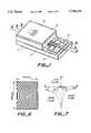
- FIG. 1is a perspective view of a miniature confocal scanning microscope in accordance with the invention
- FIG. 2is an exploded view showing the parts of the microscope of FIG. 1;
- FIG. 3is a sectional view taken along the line 3--3 of FIG. 1;
- FIG. 4is a sectional view taken along the line 4--4 of FIG. 1;
- FIG. 5is a sectional view taken along the line 5--5 of FIG. 1;
- FIG. 6shows the zone plate line schematically illustrated in FIGS. 1 and 2;
- FIG. 7shows the angles employed in the design of an off-axis zone plate lens
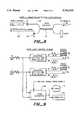
- FIG. 8shows the optical fiber illumination/detection configuration
- FIG. 9shows an open-loop electronic drive circuit associated with the scanning mirrors and the signal processing circuit
- FIG. 10shows a closed-loop electronic drive circuit associated with the scanning mirrors and the signal processing circuit
- FIG. 11shows an image of chrome lines on a glass substrate taken with a microscope in accordance with the invention
- FIG. 12shows another image of chrome lines on a glass substrate taken with a microscope in accordance with the invention.
- FIG. 13shows an image of a silicon test structure taken with a microscope in accordance with the invention.
- FIG. 14shows an image of red blood cells taken with a microscope in accordance with the invention.
- a miniature scanning confocal microscope in accordance with the inventionis illustrated in the perspective view of FIG. 1, the exploded view of FIG. 2 and the sectional views of FIGS. 3-5.
- the microscopeincludes a silicon substrate 11, a bonded silicon plate 12, a single mode optical fiber 13, a silicon spacer 14 and a fused silica lens plate 16 bonded to the silicon spacer 14.
- the plate 12includes a pair of micro-machined scanning mirrors 17, 18 disposed between the single mode optical fiber 13 and a miniature objective lens 19 formed in the silica lens plate 16.
- the silicon spacercomprises ⁇ 100> silicon which is etched to form an opening 21 which forms a ⁇ 111> face 22. Referring to FIG.
- the light beam 23 from the fiber 13is first reflected from the etched ⁇ 111> face 22 onto the first scanning mirror 17, then from a metallized mirror 24 on the lens plate 16 back to the second scanning mirror 18.
- the light beamis then reflected from the second scanning mirror 18 and passes through an off-axis zone plate objective lens 19 etched into the fused silica lens plate 16.
- the lensimages the output from the fiber to a point 26 on the sample plane. As the mirrors rotate, this point is scanned through the field of view.
- Light reflected back from the sampleis re-imaged by the lens 19, back along the same path to the fiber, and is detected and processed to create an image. Since the fiber behaves like a small pinhole, the device is a confocal microscope with the range and transverse resolution to be expected from a confocal scanning-optical microscope.
- the mirror scannersare fabricated using silicon micro-machining techniques. Micro-machined torsional mirrors for use in scanners and spatial light modulators have been reported by numerous authors. 8-14 The rotational axes of the two mirrors are orthogonal, so that one mirror scans the light beam in the x-dimension and the other mirror scans it in the y-dimension. As will be presently described, the mirrors 17, 18 are electrostatically rotated.
- the silicon substrate 11is masked and etched to form spaced wells 28, 29 below the mirrors 17, 18 whereby the mirrors can rotate.
- the substrateis masked and impurities are implanted into the substrate to form conductive regions. More particularly, two conductive regions 31, 32 are formed at the bottom of well 28 and two conductive regions 33, 34 are formed at the bottom of the well 29. These regions are connected to ion-implanted contact regions 36, 37 and 38, 39 by ion-implanted leads 41, 42 and 43, 44.
- a bonding thermal oxide layer 46is formed on the surface.
- a silicon nitride capis formed over the oxide in the wells 28, 29 to provide insulation during a subsequent metallization step.
- the silicon plate 12is bonded to the substrate via an oxide layer on the plate and the substrate oxide 46.
- a silicon nitride layer 47is formed on the plate 12 and by suitable masking and etching, windows 51, 52 and 53, 54 are formed to expose the contact regions 36, 37 and 38, 39.
- the mirrors 17, 18are defined by etching the slots 56 leaving silicon nitride strips 57, which serve as hinges. The etching removes the silicon from beneath the hinges while leaving the silicon under the mirror surfaces to provide a rigid mirror.
- a conductive layeris deposited on the top of the silicon plate to provide, on the surface of the mirrors, a reflective surface and one plate of a capacitor which cooperates with the conductive regions 31, 32 and 33, 34 to provide electrostatic forces which cause the mirrors to rotate at the hinges. Actuation of the mirrors is accomplished by applying voltages between the conductive film on the surface of the mirror and the individual implanted regions 31, 32 and 33, 34.
- the conductive filmalso covers the implanted contact regions 36, 37 and 38, 39. The film at the upper surface of the plate is not in contact with the film at the contact areas.
- the off-axis zone plate lensis fabricated using electron beam lithographic pattern transfer and anisotropic reactive ion etching.
- the angles at which the light beam enters and exits the lensare specifically designed so that the beam emitted from the lens is well focused throughout the field of view, with no second order aberrations.
- the local structure of the lens gratinghas itself been optimized to increase the efficiency of the lens relative to a similar lens designed for on-axis imaging.
- the quality of the image formed by the microscopeis governed by the design of the lens.
- Traditional microscope objectiveshave many glass elements all of which are combined to reduce the aberration of the image to a minimum.
- onebenefits from the use of a very simple, single element objective. Because a laser source illumination at a single wavelength of light is used, one can use a diffractive lens rather than the more usual refractive type. This is a distinct advantage from a manufacturing point of view since a diffractive lens can be made lithographically with tight control over the pertinent design parameters. One gives up, however, the expectation of performing aberration-free imaging when one chooses to implement the microscope with a single diffractive lens element.
- the aberrations of axially symmetric grating lensesare well known. For this application, one desires high resolution and, therefore, high numerical aperture in the objective lens.
- the primary aberration(so-called third order aberration) that limits numerical aperture in an axially symmetric grating lens with the stop at the lens is coma.
- angles ⁇ 1 , ⁇ 2 , r 1 and r 2are defined in FIG. 7.
- the phase function of this lensis such that the points in the center of the field of view, P 1 and P 2 are perfect images of one another.
- the imaging aberrations of the off-axis lensare quite similar to the aberrations of the more familiar, axially symmetric lens. Any significant deviation from this relationship would result in an instrument with extremely poor performance, and therefore the geometric relationship described above is paramount to the operation of the microscope.
- the fact that there exists a situation favorable to off-axis imagingenables one to implement the microscope With a zigzag optical path, keeping the overall dimensions very small and the design simple.
- the object and image planesare normal to the direction the beam of light is travelling. This is important for a reflection microscope, since the lens must collect the light reflected from the sample. If the sample plane was tilted with respect to the incoming beam, then the reflected light would not retrace its path back into the lens.
- the single mode optical fiber illumination/detection systemis shown in FIG. 8.
- a light source 61such as a 3 mw helium-neon laser at 632.8 nm supplies light to one end of a single-mode optical fiber 62 which is used as a flexible conduit to deliver light to the fiber 13 which serves as the point source and detector for confocal operation of the microscope.
- the single lensfocuses the light from the fiber onto the sample and collects the back-scattered light.
- a directional coupler 63directs the reflected light from the sample onto photodetector 64 to provide an output signal 66.
- each scanning mirroris driven by two symmetrically placed electrodes 31, 32 and 33, 34, one on either side of the rotational axis.
- Application of a voltage between the electrode and the mirror plateresults in an attractive electrostatic force proportional to the square of the magnitude of the voltage.
- a voltageis applied to one electrode at a time causing the mirror to deflect toward that electrode.
- a sinusoidal drive voltage 67is applied to the electrode, with a DC bias sufficient to keep the voltage always positive.
- the opposing electrodereceives a voltage 68 with the opposite phase, so that as one side sees the maximum voltage the other side sees zero voltage resulting in a net torsional force at the mirror.
- the frequency of the drive signalmay be adjusted to cause the mirror to oscillate at its natural resonance or off resonance. Near resonance, the motion of the mirror will be phase shifted relative to the drive voltage waveform.
- a scan converter 69is used for this purpose, which takes as its input the drive signals and the detected optical signal from the fiber, and produces as its output a raster scanned image suitable to display on a monitor 71 or for capture on a computer 72.
- the simplestis open loop control, FIG. 9, where it is assumed that the kinetic response to the mirrors is known well enough that one only need to monitor the drive voltage in order to predict the mirror position. Then the scan converter maps the intensity of the detected optical signal to the calculated position of the beam.
- the other schemeis closed loop control, FIG. 10, where the position of the mirrors is independently monitored and this information is used in a feedback scheme that attempts to lock the motion of the mirrors to the drive voltage waveform.
- One of the simplest ways to monitor the position of the mirroris to measure the capacitance between the mirror plate and the drive electrodes. This capacitance will vary with the angular position of the mirror, so that monitoring the capacitance fluctuation provides a direct measure of the mirror position.
- the control loopis capable of making the mirror motion exactly follow the drive voltage, so that the scan converter may use the x and y drive signals directly to map the intensity to the proper position of the beam, without any specific knowledge of the mirror kinetics.
- a microscopewas constructed which was 6 mm long, 2.5 mm wide and 1 mm high.
- the scanning mirror 17was 300 ⁇ m by 360 ⁇ m and the scanning mirror 18 was 500 ⁇ m by 600 ⁇ m.
- the single mode optical fiber 13was 125 ⁇ m in diameter.
- the microscopewas operated to provide both raster-scan and lissajous-scan images.
- the microscopewas used to scan a glass substrate provided with chrome lines 2 ⁇ m wide on 4 ⁇ m centers and a 5 ⁇ m line.
- the mirror 17was scanned at a frequency of 2.71 kHz with approximately 20V peak-to-peak sinusoidal voltage.
- the mirror 18was driven at a frequency of 5 Hz with approximately 25 peak-to-peak sinusoidal voltage.
- the field of viewwas 30 ⁇ 24 ⁇ m.
- the resulting raster-scan imageis shown in FIG. 11, which has 271 lines/frame at a frame rate of 5 Hz.
- the 2 ⁇ m linesare shown at 76 and the 5 ⁇ m line is shown at 77.
- the microscopewas used to scan a glass substrate with chrome lines 2 ⁇ m wide on 4 ⁇ m centers and 5 ⁇ m lines on 10 ⁇ m centers.
- the mirror 17was scanned at a frequency of 4.3 kHz with approximately 30V peak-to-peak sinusoidal voltage.
- the mirror 18was driven at a frequency of 1.07 kHz with approximately 25V peak-to-peak sinusoidal voltage.
- the field of viewwas about 80 ⁇ m ⁇ 60 ⁇ m.
- the resulting lissajous-scan imageis shown in FIG. 12.
- the frame ratewas 8 Hz with 268 lines/frame.
- the 2 ⁇ m and 5 ⁇ m linesare shown at 78 and 79.
- the microscopewas used to scan an etched silicon test structure having U-shaped trenches.
- the mirror 17was scanned at a frequency of 4.3 kHz with 30V peak-to-peak sinusoidal voltage, giving a field of view of 80 ⁇ m ⁇ 60 ⁇ m.
- the resulting Lissajous-scan imageis shown in FIG. 13.
- the trenchesare shown at 81.
- the frame ratewas 8 Hz with 268 lines/frame.
- the microscopewas used to scan red blood cells on a glass slide.
- the mirror 17was scanned at a frequency of 4.3 kHz with a 30V peak-to-peak sinusoidal drive voltage.
- the mirror 18was driven at a frequency of 1.07 kHz with a 15V peak-to-peak drive voltage.
- the field of viewwas 40 ⁇ m ⁇ 60 ⁇ m.
- the resulting Lissajous-scan imageis shown in FIG. 14.
- the red cellsare shown at 82.
- the frame ratewas 8 Hz with 268 lines/frame.
- the mirrorsmay be cantilevered or supported on a single post.
- the off-axis grating lenscould be a reflecting type lens.
- the micro-machined microscopecan be further miniaturized to provide a scanning microscope which can be mounted inside a hypodermic needle.
- a miniature scanning confocal microscopemaking use of micro-machined scanning mirrors and parts.
Landscapes
- Physics & Mathematics (AREA)
- Optics & Photonics (AREA)
- General Physics & Mathematics (AREA)
- Analytical Chemistry (AREA)
- Chemical & Material Sciences (AREA)
- Surgery (AREA)
- Health & Medical Sciences (AREA)
- Radiology & Medical Imaging (AREA)
- Ophthalmology & Optometry (AREA)
- General Health & Medical Sciences (AREA)
- Microscoopes, Condenser (AREA)
- Mechanical Optical Scanning Systems (AREA)
- Light Guides In General And Applications Therefor (AREA)
- Instruments For Viewing The Inside Of Hollow Bodies (AREA)
Abstract
Description
This application claims the priority of Provisional Application Serial No. 60/006303 filed Nov. 11, 1995.
This invention relates generally to miniature confocal microscopes and more particularly to scanning confocal microscopes using micro-machined mirrors.
The standard optical microscope, used routinely in biology, medicine and semiconductor processing, is large. Typically, samples of tissue are observed in vitro after being mounted on a microscope slide. Such microscopes are not suitable for in vivo observations of the skin or internal organs of the human body; they are just too large. Consequently, there is a need for a small microscope which could be used for observations of melanomas of the skin, and the teeth and gums, and for endoscopy of cells inside arteries and veins and organs of the body. Ultimately, if such a microscope could be mounted inside a hypodermic needle, it would be suitable for taking in vivo biopsies and for observing microscopic features of the body, such as the flow of blood and plasma in veins, arteries, and other vessels of the body, the fluid in tear ducts, and the general condition of small vessels. Although we have described biological applications of a miniature microscope, the miniature microscope of the present invention can be used in endoscopes passed through small pipes, and for use in in-situ observation during processing of semiconductors and other materials.
The present tendency is to carry out clinical procedures with small tools mounted in catheters, to make internal observations inside vessels with fiber optic devices, and to carry out operations using laser and fiber-optic techniques. Much less damage is done to the body than with older surgical methods by using such procedures. Observations of what is being done on a microscopic scale would be helpful, since the best resolution that presently can be obtained with endoscopes is of the order of 10-20 μm. Another example is the observation of cancer cells in the uterus, where it is extremely painful to carry out biopsies. An in vivo imaging technique for this purpose which leaves the tissue intact would be a considerable improvement over present practice.
Several fiber optic microscopes have been suggested in the past, but either they are too bulky or too slow, so that the frame time is of the order of several seconds, or the definition is very poor1-6. Thus, these microscopes are not suitable for in vivo real-time imaging at the microscopic level.
We reported a vibrating fiber microscope in a recent paper7. A Fresnel lens made by photolithographic means was mounted on the end of a vibrating glass rod approximately 0.8 mm square. The lens was illuminated from an optical fiber glued to the other end of the rod, and formed a spot of the order of 1.8 μm in diameter at an approximate distance of 1 mm from the lens. Light reflected from the object being observed was passed back through the fiber and lens to a detector. The signal from the detector, after suitable processing, was displayed through an image converter as a video image. The rectangular-shaped rod was vibrated by electrostatic fields, applied between it and an outer tube, at its slightly different mechanical resonant frequencies in the x and y directions. Hence, the focused spot from the lens formed a raster pattern (a Lissajous figure). The vibration frequencies were of the order of 8 kHz, and a single frame of the image took about 1/20 second to form. The resolution was about 2 μm. This microscope suffered from the disadvantage that the vibrating rod needed support from a rigid and massive structure, which made the supporting structure large and unsuitable for use in the body.
It is an object of this invention to provide a micro-machined miniature scanning optical microscope.
It is another object of the invention to provide a miniature scanning optical microscope using micro-machined, electrostatically actuated scanning mirrors.
It is still another object of the invention to provide a miniature scanning optical microscope using micro-machined, electrostatically actuated scanning mirrors and a micro-machined binary lens.
There is provided a scanning optical microscope which incorporates electrostatically actuated scanning mirrors disposed between a single-mode optical fiber light source/detector and a focusing objective lens.
The foregoing and other objects of the invention will be more fully understood from the following description read in connection with the accompanying drawings, of which:
FIG. 1 is a perspective view of a miniature confocal scanning microscope in accordance with the invention;
FIG. 2 is an exploded view showing the parts of the microscope of FIG. 1;
FIG. 3 is a sectional view taken along the line 3--3 of FIG. 1;
FIG. 4 is a sectional view taken along the line 4--4 of FIG. 1;
FIG. 5 is a sectional view taken along the line 5--5 of FIG. 1;
FIG. 6 shows the zone plate line schematically illustrated in FIGS. 1 and 2;
FIG. 7 shows the angles employed in the design of an off-axis zone plate lens;
FIG. 8 shows the optical fiber illumination/detection configuration;
FIG. 9 shows an open-loop electronic drive circuit associated with the scanning mirrors and the signal processing circuit
FIG. 10 shows a closed-loop electronic drive circuit associated with the scanning mirrors and the signal processing circuit;
FIG. 11 shows an image of chrome lines on a glass substrate taken with a microscope in accordance with the invention;
FIG. 12 shows another image of chrome lines on a glass substrate taken with a microscope in accordance with the invention;
FIG. 13 shows an image of a silicon test structure taken with a microscope in accordance with the invention; and
FIG. 14 shows an image of red blood cells taken with a microscope in accordance with the invention.
A miniature scanning confocal microscope in accordance with the invention is illustrated in the perspective view of FIG. 1, the exploded view of FIG. 2 and the sectional views of FIGS. 3-5. The microscope includes a silicon substrate 11, abonded silicon plate 12, a single modeoptical fiber 13, asilicon spacer 14 and a fusedsilica lens plate 16 bonded to thesilicon spacer 14. Theplate 12 includes a pair ofmicro-machined scanning mirrors optical fiber 13 and a miniatureobjective lens 19 formed in thesilica lens plate 16. The silicon spacer comprises <100> silicon which is etched to form anopening 21 which forms a <111>face 22. Referring to FIG. 3, thelight beam 23 from thefiber 13 is first reflected from the etched <111>face 22 onto thefirst scanning mirror 17, then from ametallized mirror 24 on thelens plate 16 back to thesecond scanning mirror 18. The light beam is then reflected from thesecond scanning mirror 18 and passes through an off-axis zone plateobjective lens 19 etched into the fusedsilica lens plate 16. The lens images the output from the fiber to apoint 26 on the sample plane. As the mirrors rotate, this point is scanned through the field of view. Light reflected back from the sample is re-imaged by thelens 19, back along the same path to the fiber, and is detected and processed to create an image. Since the fiber behaves like a small pinhole, the device is a confocal microscope with the range and transverse resolution to be expected from a confocal scanning-optical microscope.
The mirror scanners are fabricated using silicon micro-machining techniques. Micro-machined torsional mirrors for use in scanners and spatial light modulators have been reported by numerous authors.8-14 The rotational axes of the two mirrors are orthogonal, so that one mirror scans the light beam in the x-dimension and the other mirror scans it in the y-dimension. As will be presently described, themirrors
The silicon substrate 11 is masked and etched to form spacedwells mirrors conductive regions conductive regions contact regions thermal oxide layer 46 is formed on the surface. A silicon nitride cap is formed over the oxide in thewells
Thesilicon plate 12 is bonded to the substrate via an oxide layer on the plate and thesubstrate oxide 46. Asilicon nitride layer 47 is formed on theplate 12 and by suitable masking and etching,windows contact regions mirrors slots 56 leaving silicon nitride strips 57, which serve as hinges. The etching removes the silicon from beneath the hinges while leaving the silicon under the mirror surfaces to provide a rigid mirror. After the mirrors have been defined, a conductive layer is deposited on the top of the silicon plate to provide, on the surface of the mirrors, a reflective surface and one plate of a capacitor which cooperates with theconductive regions regions contact regions
The off-axis zone plate lens, FIG. 6, is fabricated using electron beam lithographic pattern transfer and anisotropic reactive ion etching. The angles at which the light beam enters and exits the lens are specifically designed so that the beam emitted from the lens is well focused throughout the field of view, with no second order aberrations. The local structure of the lens grating has itself been optimized to increase the efficiency of the lens relative to a similar lens designed for on-axis imaging.
The quality of the image formed by the microscope is governed by the design of the lens. Traditional microscope objectives have many glass elements all of which are combined to reduce the aberration of the image to a minimum. For this invention, one benefits from the use of a very simple, single element objective. Because a laser source illumination at a single wavelength of light is used, one can use a diffractive lens rather than the more usual refractive type. This is a distinct advantage from a manufacturing point of view since a diffractive lens can be made lithographically with tight control over the pertinent design parameters. One gives up, however, the expectation of performing aberration-free imaging when one chooses to implement the microscope with a single diffractive lens element.
The aberrations of axially symmetric grating lenses are well known. For this application, one desires high resolution and, therefore, high numerical aperture in the objective lens. The primary aberration (so-called third order aberration) that limits numerical aperture in an axially symmetric grating lens with the stop at the lens is coma.
With the zigzag optical path used for the microscope, one requires a lens that is not axially symmetric, but is designed to create an image from a beam of light that is incident at an angle from the lens normal. In general, such an off-axis lens will suffer from a more serious second order aberration called linear astigmatism. It has been discovered, however, that if the angles of incidence of the object beam and the image beam are chosen properly then the second order astigmatism disappears and imaging is again governed by third order coma. The constraint on the angles is that
sin (α.sub.1)/r.sub.1 =sin (α.sub.2)/r.sub.2
where the angles α1, α2, r1 and r2 are defined in FIG. 7.
The phase function of this lens is such that the points in the center of the field of view, P1 and P2 are perfect images of one another.
When the microscope is constructed with regard to this constraint on the angles made by the incoming and exiting beams with the normal to the lens plane, then the imaging aberrations of the off-axis lens are quite similar to the aberrations of the more familiar, axially symmetric lens. Any significant deviation from this relationship would result in an instrument with extremely poor performance, and therefore the geometric relationship described above is paramount to the operation of the microscope. On the other hand, the fact that there exists a situation favorable to off-axis imaging enables one to implement the microscope With a zigzag optical path, keeping the overall dimensions very small and the design simple.
Note finally from the figure that the object and image planes are normal to the direction the beam of light is travelling. This is important for a reflection microscope, since the lens must collect the light reflected from the sample. If the sample plane was tilted with respect to the incoming beam, then the reflected light would not retrace its path back into the lens.
The single mode optical fiber illumination/detection system is shown in FIG. 8. Alight source 61, such as a 3 mw helium-neon laser at 632.8 nm supplies light to one end of a single-modeoptical fiber 62 which is used as a flexible conduit to deliver light to thefiber 13 which serves as the point source and detector for confocal operation of the microscope. The single lens focuses the light from the fiber onto the sample and collects the back-scattered light. Adirectional coupler 63 directs the reflected light from the sample ontophotodetector 64 to provide anoutput signal 66.
The scanning microscope electronic interface is simple in principle. Referring to FIGS. 9 and 10, each scanning mirror is driven by two symmetrically placedelectrodes sinusoidal drive voltage 67 is applied to the electrode, with a DC bias sufficient to keep the voltage always positive. The opposing electrode receives avoltage 68 with the opposite phase, so that as one side sees the maximum voltage the other side sees zero voltage resulting in a net torsional force at the mirror. The frequency of the drive signal may be adjusted to cause the mirror to oscillate at its natural resonance or off resonance. Near resonance, the motion of the mirror will be phase shifted relative to the drive voltage waveform. In order to form an image from the detected light reflected from the sample, it is necessary to know the precise position of the mirror. Ascan converter 69 is used for this purpose, which takes as its input the drive signals and the detected optical signal from the fiber, and produces as its output a raster scanned image suitable to display on amonitor 71 or for capture on acomputer 72.
There are two possible control schemes. The simplest is open loop control, FIG. 9, where it is assumed that the kinetic response to the mirrors is known well enough that one only need to monitor the drive voltage in order to predict the mirror position. Then the scan converter maps the intensity of the detected optical signal to the calculated position of the beam. The other scheme is closed loop control, FIG. 10, where the position of the mirrors is independently monitored and this information is used in a feedback scheme that attempts to lock the motion of the mirrors to the drive voltage waveform. One of the simplest ways to monitor the position of the mirror is to measure the capacitance between the mirror plate and the drive electrodes. This capacitance will vary with the angular position of the mirror, so that monitoring the capacitance fluctuation provides a direct measure of the mirror position. With closed loop control, the control loop is capable of making the mirror motion exactly follow the drive voltage, so that the scan converter may use the x and y drive signals directly to map the intensity to the proper position of the beam, without any specific knowledge of the mirror kinetics.
A microscope was constructed which was 6 mm long, 2.5 mm wide and 1 mm high. Thescanning mirror 17 was 300 μm by 360 μm and thescanning mirror 18 was 500 μm by 600 μm. The single modeoptical fiber 13 was 125 μm in diameter.
The microscope was operated to provide both raster-scan and lissajous-scan images. In the first example, the microscope was used to scan a glass substrate provided with chrome lines 2 μm wide on 4 μm centers and a 5 μm line. Themirror 17 was scanned at a frequency of 2.71 kHz with approximately 20V peak-to-peak sinusoidal voltage. Themirror 18 was driven at a frequency of 5 Hz with approximately 25 peak-to-peak sinusoidal voltage. The field of view was 30×24 μm. The resulting raster-scan image is shown in FIG. 11, which has 271 lines/frame at a frame rate of 5 Hz. The 2 μm lines are shown at 76 and the 5 μm line is shown at 77.
In the second example, the microscope was used to scan a glass substrate with chrome lines 2 μm wide on 4 μm centers and 5 μm lines on 10 μm centers. Themirror 17 was scanned at a frequency of 4.3 kHz with approximately 30V peak-to-peak sinusoidal voltage. Themirror 18 was driven at a frequency of 1.07 kHz with approximately 25V peak-to-peak sinusoidal voltage. The field of view was about 80 μm×60 μm. The resulting lissajous-scan image is shown in FIG. 12. The frame rate was 8 Hz with 268 lines/frame. The 2 μm and 5 μm lines are shown at 78 and 79.
In another example, the microscope was used to scan an etched silicon test structure having U-shaped trenches. Themirror 17 was scanned at a frequency of 4.3 kHz with 30V peak-to-peak sinusoidal voltage, giving a field of view of 80 μm×60 μm. The resulting Lissajous-scan image is shown in FIG. 13. The trenches are shown at 81. The frame rate was 8 Hz with 268 lines/frame.
In a fourth example, the microscope was used to scan red blood cells on a glass slide. Themirror 17 was scanned at a frequency of 4.3 kHz with a 30V peak-to-peak sinusoidal drive voltage. Themirror 18 was driven at a frequency of 1.07 kHz with a 15V peak-to-peak drive voltage. The field of view was 40 μm×60 μm. The resulting Lissajous-scan image is shown in FIG. 14. The red cells are shown at 82. The frame rate was 8 Hz with 268 lines/frame.
Although a specific embodiment of the invention has been provided, modifications can be made without departing from the invention. For example, the mirrors may be cantilevered or supported on a single post. The off-axis grating lens could be a reflecting type lens. The micro-machined microscope can be further miniaturized to provide a scanning microscope which can be mounted inside a hypodermic needle. Thus, there has been provided a miniature scanning confocal microscope making use of micro-machined scanning mirrors and parts.
1. L. Giniunas, R. Juskaitis & S. J. Shatalin, "Scanning fiber optic microscope," Elect. Lett. 27, 724-726 (1991).
2. T. Dabbs & M. Glass, "Fiber-optic confocal microscope--FOCON," Appl.Opt 31, 3030-3035 (1993).
3. L. Giniunas, R. Juskaitis & S. J. Shatalin, "Endoscope with optical sectioning capability," Appl. Opt. 32, 2888-2890 (1993).
4. R. Juskaitis & T. Wilson, "Direct-view fiber-optic confocal microscope," Opt. Lett. 19, 1906-1908 (1994).
5. P. M. Delaney, M. R. Harris & R. G. King, "Fiber optic laser scanning confocal microscope suitable for fluorescence imaging," Appl. Opt. 33, 573-577 (1994).
6. A. F. Gmitro & D. Azis, "Confocal microscope through a fiber-optic imaging bundle," Opt. Lett. 18, 565-567 (1993).
7. D. Dickensheets & G. S. Kino "A Scanned Optical Fiber Confocal Microscope," Proc. SPIE, 2184, 39-47 (1994).
8. K. E. Petersen, "Silicon Torsional Scanning Mirror," IBM J. Res. Dev., 24, 631-637 (1980).
9. M. G. Allen, M. Scheidel & R. L. Smith, "Movable Micromachined Silicon Plates with Integrated Position Sensing," Sensors and Actuators, A21-A23, 211-214 (1990).
10. V. P. Jaecklin, C. Linder, N. F. deRooij, J. M. Moret, R. Vuilleumier, "Line-addressable torsional micromirrors for light modulator arrays," Sensors and Actuators, A41-42, 324-329 (1990).
11. M. Fischer, H. Graef, W. von Munch, "Electrostatically deflectable polysilicon torsional mirrors," Sensors and Actuators, A44, 83-89 (1994).
12. K. E. Mattsson, "Surface micromachined scanning mirrors,"Microelectronic Engineering 19, 199-204 (1992).
13. L. J. Hornbeck, "Spatial light modulator and method," U.S. Pat. No. 5,061,049, Oct. 29, 1991.
14. L. J. Hornbeck, "Spatial light modulator," U.S. Pat. No. 4,956,619, Sep. 11, 1990.
Claims (12)
1. A scanning optical microscope of the type which includes a single mode optical fiber having one end which serves as a point source of light, and a lens for focusing the light from the end of the fiber onto a point on a focal plane, and for gathering light reflected from said point and focusing said light onto the end of the optical fiber, characterized in that it includes:
a first micro-machined scanning mirror to receive the light from the fiber and scans the light along a first direction, and
a second micro-machined scanning mirror coplanar with said first micro-machined scanning mirror to receive the light from the first mirror and scans said light in an orthogonal direction, whereby the point on the focal plane is scanned in said first and second directions.
2. A scanning optical microscope as in claim 1 which includes an inclined reflector for receiving light from the optical fiber and directing it onto the first micro-machined scanning mirror, and a reflector disposed to receive light from said first micro-machined scanning mirror and reflect it onto the second micro-machined scanning mirror, which directs it to the focusing lens.
3. A scanning optical microscope including:
a silicon substrate including first and second wells;
a first pair of ion-implanted conductive regions in said first well;
a second pair of ion-implanted conductive regions in said second well;
a first micro-machined scanning mirror hingedly supported above said first well for rotation about a first axis;
a second micro-machined scanning mirror hingedly supported above said second well for rotation about a second orthogonal axis;
a conductive reflective film carried on the surface of said first and second scanning mirrors which, together with the conductive regions in said wells, form spaced plates which are electrostatically driven with respect to one another to thereby rotate said mirrors;
an optical fiber serving as a point source of light, said first scanning mirror scanning the light from the optical fiber in a first direction and said second mirror scanning the light in an orthogonal direction; and
a lens for receiving the light scanned by said mirrors and focusing it at scanned points on an image plane and for receiving light reflected from said plane and directing it back to the optical fiber.
4. A scanning optical microscope as in claim 3 which includes an inclined reflector for receiving light from the optical fiber and directing it into the first mirror and a reflector disposed to receive light from the first mirror and reflect it onto the second mirror which directs it to the focusing lens.
5. A scanning optical microscope as in claim 3 wherein the mirrors are coplanar.
6. A scanning optical microscope including:
a silicon substrate including first and second wells;
a first pair of ion-implanted conductive regions in said first well;
a second pair of ion-implanted conductive regions in said second well;
a first micro-machined scanning mirror hingedly supported above said first well for rotation about a first axis;
a second micro-machined scanning mirror hingedly supported above said second well for rotation about a second orthogonal axis;
a conductive reflective film carried on the surface of said first and second scanning mirrors which, together with the conductive regions in said wells, form spaced plates which are electrostatically driven with respect to one another to thereby rotate said mirrors;
an optical fiber serving as a point source of light, said first scanning mirror scanning the light from the optical fiber in a first direction and said second mirror scanning the light in an orthogonal direction; and
an off-axis binary lens for receiving the light scanned by said mirrors and focusing it at scanned points on an image plane and for receiving light reflected from said plane and directing it back to the optical fiber.
7. A scanning optical microscope of the type which includes a single mode optical fiber having one end which serves as a point source of light, and a lens for focusing the light from the end of the fiber onto a point on a focal plane, and for gathering light reflected from said point and focusing said light onto the end of the optical fiber, characterized in that it includes:
a first micro-machined scanning mirror supported for rotation by spaced silicon-nitride hinges for receiving light from the fiber and scanning the light along a first direction, and
a second micro-machined scanning mirror coplanar with said first micro-machined scanning mirror supported for rotation by spaced silicon-nitride hinges for receiving light from the first mirror and scanning said light in an orthogonal direction, whereby the point on the focal plane is scanned in said first and second directions.
8. A scanning optical microscope as in claim 7 which includes an inclined reflector for receiving light from the optical fiber and directing it onto the first mirror, and a reflector disposed to receive light from said first mirror and reflect it onto the second mirror, which directs it to the focusing lens.
9. A scanning optical microscope of the type which includes a single mode optical fiber having one end which serves as a point source of light, and an off-axis binary lens for focusing the light from the end of the fiber onto a point on a focal plane, and for gathering light reflected from said point and focusing said light onto the end of the optical fiber, characterized in that it includes:
a first micro-machined scanning mirror supported for rotation by spaced silicon-nitride hinges for receiving light from the fiber and scanning the light along a first direction, and
a second micro-machined scanning mirror supported for rotation by spaced silicon-nitride hinges for receiving light from the first mirror and scanning said light in an orthogonal direction, whereby the point on the focal plane is scanned in said first and second directions.
10. A scanning optical microscope including:
a silicon substrate including first and second wells;
a first pair of ion-implanted conductive regions in said first well;
a second pair of ion-implanted conductive regions in said second well;
a first micro-machined scanning mirror hingedly supported above said first well by spaced silicon-nitride hinges for rotation about a first axis;
a second micro-machined scanning mirror coplanar with said first micro-machined scanning mirror hingedly supported above said second well by spaced silicon-nitride hinges for rotation about a second orthogonal axis;
a conductive reflective film carried on the surface of said first and second scanning mirrors which, together with the conductive regions in said wells, form spaced plates which are electrostatically driven with respect to one another to thereby rotate said mirrors;
an optical fiber serving as a point source of light, said first scanning mirror scanning the light from the optical fiber in a first direction and said second mirror scanning the light in an orthogonal direction; and
a focusing lens for receiving the light scanned by said mirrors and focusing it at scanned points on an image plane and for receiving light reflected from said plane and directing it back to the optical fiber.
11. A scanning optical microscope as in claim 10 which includes an inclined reflector for receiving light from the optical fiber and directing it into the first mirror and a reflector disposed to receive light from the first mirror and reflect it onto the second mirror which directs it to said focusing lens.
12. A scanning optical microscope including:
a silicon substrate including first and second wells;
a first pair of ion-implanted conductive regions in said first well;
a second pair of ion-implanted conductive regions in said second well;
a first micro-machined scanning mirror hingedly supported above said first well by spaced silicon-nitride hinges for rotation about a first axis;
a second micro-machined scanning mirror hingedly supported above said second well by spaced silicon-nitride hinges for rotation about a second orthogonal axis;
a conductive reflective film carried on the surface of said first and second scanning mirrors which, together with the conductive regions in said wells, form spaced plates which are eIectrostatically driven with respect to one another to thereby rotate said mirrors;
an optical fiber serving as a point source of light, said first scanning mirror scanning the light from the optical fiber in a first direction and said second mirror scanning the light in an orthogonal direction; and
an off-axis binary focusing lens for receiving the light scanned by said mirrors and focusing it at scanned points on an image plane and for receiving light reflected from said plane and directing it back to the optical fiber.
Priority Applications (8)
| Application Number | Priority Date | Filing Date | Title |
|---|---|---|---|
| US08/575,687US5742419A (en) | 1995-11-07 | 1995-12-19 | Miniature scanning confocal microscope |
| JP8294997AJP3032720B2 (en) | 1995-11-07 | 1996-11-07 | Small scanning confocal microscope |
| US08/797,931US5907425A (en) | 1995-12-19 | 1997-02-12 | Miniature scanning confocal microscope |
| US08/998,187US6007208A (en) | 1995-12-19 | 1997-12-24 | Miniature scanning confocal microscope |
| US09/070,699US6749346B1 (en) | 1995-11-07 | 1998-04-30 | Miniature scanning confocal microscope |
| US09/205,576US6088145A (en) | 1995-12-19 | 1998-12-04 | Miniature scanning confocal microscope |
| US09/316,455US6154305A (en) | 1995-12-19 | 1999-05-21 | Miniature scanning confocal microscope |
| JP25852199AJP3330906B2 (en) | 1995-11-07 | 1999-09-13 | Small scanning confocal microscope |
Applications Claiming Priority (2)
| Application Number | Priority Date | Filing Date | Title |
|---|---|---|---|
| US630395P | 1995-11-07 | 1995-11-07 | |
| US08/575,687US5742419A (en) | 1995-11-07 | 1995-12-19 | Miniature scanning confocal microscope |
Related Child Applications (1)
| Application Number | Title | Priority Date | Filing Date |
|---|---|---|---|
| US08/797,931Continuation-In-PartUS5907425A (en) | 1995-11-07 | 1997-02-12 | Miniature scanning confocal microscope |
Publications (1)
| Publication Number | Publication Date |
|---|---|
| US5742419Atrue US5742419A (en) | 1998-04-21 |
Family
ID=26675452
Family Applications (1)
| Application Number | Title | Priority Date | Filing Date |
|---|---|---|---|
| US08/575,687Expired - LifetimeUS5742419A (en) | 1995-11-07 | 1995-12-19 | Miniature scanning confocal microscope |
Country Status (2)
| Country | Link |
|---|---|
| US (1) | US5742419A (en) |
| JP (2) | JP3032720B2 (en) |
Cited By (129)
| Publication number | Priority date | Publication date | Assignee | Title |
|---|---|---|---|---|
| US5889641A (en)* | 1997-05-05 | 1999-03-30 | Seagate Technology, Inc. | Magneto-resistive magneto-optical head |
| US5940549A (en)* | 1996-07-30 | 1999-08-17 | Seagate Technology, Incorporated | Optical system and method using optical fibers for storage and retrieval of information |
| US6002507A (en)* | 1998-12-01 | 1999-12-14 | Xerox Corpoation | Method and apparatus for an integrated laser beam scanner |
| US6034938A (en)* | 1996-07-30 | 2000-03-07 | Seagate Technology, Inc. | Data storage system having an optical processing flying head |
| US6044056A (en)* | 1996-07-30 | 2000-03-28 | Seagate Technology, Inc. | Flying optical head with dynamic mirror |
| US6046966A (en)* | 1998-06-10 | 2000-04-04 | Seagate Technology, Inc. | Magneto-optical data storage system |
| US6057952A (en)* | 1999-01-14 | 2000-05-02 | Olympus Optical Co., Ltd. | Light scanning device and confocal optical device using the same |
| US6058094A (en)* | 1996-07-30 | 2000-05-02 | Seagate Technology Inc. | Flying magneto-optical head with a steerable mirror |
| US6061323A (en)* | 1996-07-30 | 2000-05-09 | Seagate Technology, Inc. | Data storage system having an improved surface micro-machined mirror |
| US6075639A (en)* | 1997-10-22 | 2000-06-13 | The Board Of Trustees Of The Leland Stanford Junior University | Micromachined scanning torsion mirror and method |
| US6076256A (en)* | 1997-04-18 | 2000-06-20 | Seagate Technology, Inc. | Method for manufacturing magneto-optical data storage system |
| US6081499A (en)* | 1997-05-05 | 2000-06-27 | Seagate Technology, Inc. | Magneto-optical data storage system having an optical-processing flying head |
| US6140979A (en)* | 1998-08-05 | 2000-10-31 | Microvision, Inc. | Scanned display with pinch, timing, and distortion correction |
| US6151167A (en)* | 1998-08-05 | 2000-11-21 | Microvision, Inc. | Scanned display with dual signal fiber transmission |
| US6172789B1 (en)* | 1999-01-14 | 2001-01-09 | The Board Of Trustees Of The Leland Stanford Junior University | Light scanning device and confocal optical device using the same |
| US6178150B1 (en) | 1996-07-30 | 2001-01-23 | Seagate Technology Inc. | Offset optics for use with optical heads |
| US6200882B1 (en) | 1998-06-10 | 2001-03-13 | Seagate Technology, Inc. | Method for processing a plurality of micro-machined mirror assemblies |
| WO2001024686A1 (en) | 1999-10-06 | 2001-04-12 | Olympus Optical Co., Ltd. | Optical scanning probe system |
| US6226233B1 (en) | 1996-07-30 | 2001-05-01 | Seagate Technology, Inc. | Magneto-optical system utilizing MSR media |
| US6252747B1 (en) | 1997-11-13 | 2001-06-26 | Teac Corporation | Disk apparatus having an improved head carriage structure |
| US6292287B1 (en) | 1999-05-20 | 2001-09-18 | Olympus Optical Co., Ltd. | Scanning confocal optical device |
| US6362912B1 (en) | 1999-08-05 | 2002-03-26 | Microvision, Inc. | Scanned imaging apparatus with switched feeds |
| US6369931B1 (en)* | 1997-12-22 | 2002-04-09 | Robert Bosch Gmbh | Method for manufacturing a micromechanical device |
| US6388809B1 (en) | 1997-10-29 | 2002-05-14 | Digital Optical Imaging Corporation | Methods and apparatus for improved depth resolution use of out-of-focus information in microscopy |
| EP1225469A3 (en)* | 2000-12-06 | 2002-07-31 | Xerox Corporation | Integrated micro-opto-electro-mechanical laser scanner |
| US6433910B2 (en) | 2000-04-28 | 2002-08-13 | Olympus Optical Co., Ltd. | Confocal optical system |
| US6433907B1 (en) | 1999-08-05 | 2002-08-13 | Microvision, Inc. | Scanned display with plurality of scanning assemblies |
| US20020115908A1 (en)* | 2000-06-30 | 2002-08-22 | Inner Vision Imaging, L.L.C. | Endoscope |
| US6445362B1 (en) | 1999-08-05 | 2002-09-03 | Microvision, Inc. | Scanned display with variation compensation |
| US6450949B1 (en) | 2000-06-30 | 2002-09-17 | Inner Vision Imaging, Inc. | Endoscope |
| US6483626B2 (en) | 1999-03-05 | 2002-11-19 | Olympus Optical Co., Ltd. | Direct-view-type confocal point optical system |
| US6483641B1 (en) | 1997-10-29 | 2002-11-19 | Digital Optical Imaging Corporation | Apparatus and methods relating to spatially light modulated microscopy |
| US20020179828A1 (en)* | 2001-05-30 | 2002-12-05 | Leica Microsystems Heidelberg Gmbh | Method and device for point-by-point scanning of a specimen |
| US6515781B2 (en) | 1999-08-05 | 2003-02-04 | Microvision, Inc. | Scanned imaging apparatus with switched feeds |
| US20030034431A1 (en)* | 2000-07-28 | 2003-02-20 | Mandella Michael J. | Fiber-coupled, high-speed, integrated, angled-dual-axis confocal scanning microscopes employing vertical cross-section scanning |
| US20030058190A1 (en)* | 2001-09-21 | 2003-03-27 | Microvision, Inc. | Scanned display with pinch, timing, and distortion correction |
| US6545260B1 (en) | 1999-11-19 | 2003-04-08 | Olympus Optical Co., Ltd. | Light scanning optical device which acquires a high resolution two-dimensional image without employing a charge-coupled device |
| US6574015B1 (en) | 1998-05-19 | 2003-06-03 | Seagate Technology Llc | Optical depolarizer |
| US6583772B1 (en) | 1998-08-05 | 2003-06-24 | Microvision, Inc. | Linked scanner imaging system and method |
| EP1255149A3 (en)* | 2001-04-30 | 2003-09-24 | Xerox Corporation | A micro-opto-electro-mechanical system (MOEMS) |
| US6661393B2 (en) | 1999-08-05 | 2003-12-09 | Microvision, Inc. | Scanned display with variation compensation |
| US6663560B2 (en) | 1999-12-17 | 2003-12-16 | Digital Optical Imaging Corporation | Methods and apparatus for imaging using a light guide bundle and a spatial light modulator |
| US20030234994A1 (en)* | 2002-06-19 | 2003-12-25 | Pan Shaoher X. | Reflective spatial light modulator |
| WO2004000720A1 (en)* | 2002-06-19 | 2003-12-31 | Miradia, Inc. | Fabrication of a reflective spatial light modulator |
| US20040004753A1 (en)* | 2002-06-19 | 2004-01-08 | Pan Shaoher X. | Architecture of a reflective spatial light modulator |
| US20040006576A1 (en)* | 2002-07-03 | 2004-01-08 | Sean Colbath | Systems and methods for providing multimedia information management |
| US20040021923A1 (en)* | 1999-06-30 | 2004-02-05 | Hoffman Resources Llc | Apparatus and method for optical raster-scanning in a micromechanical system |
| WO2003078303A3 (en)* | 2002-03-15 | 2004-02-26 | Colibrys S A | Fabrication process for optical mems device for fiber alignment and variable optical attenuation |
| US20040051957A1 (en)* | 2002-08-06 | 2004-03-18 | Dmetrix, Inc. | Miniature microscope objective lens |
| US6710316B2 (en) | 2000-07-28 | 2004-03-23 | Optical Biopsy Technologies, Inc. | Fiber-coupled, high-speed, angled-dual-axis optical coherence scanning microscopes |
| EP0961150A3 (en)* | 1998-06-01 | 2004-05-19 | Lucent Technologies Inc. | Micro-opto-electromechanical devices and method therefor |
| US20040096118A1 (en)* | 2002-11-20 | 2004-05-20 | Dmetrix, Inc. | Multi-spectral miniature microscope array |
| US20040097791A1 (en)* | 2002-11-13 | 2004-05-20 | Olympus Corporation | Endoscope |
| US20040122289A1 (en)* | 2002-11-05 | 2004-06-24 | Pentax Corporation | Confocal probe and endoscope device |
| US20040147810A1 (en)* | 2003-01-21 | 2004-07-29 | Pentax Corporation | Endoscope probe system |
| US20040173738A1 (en)* | 2003-02-24 | 2004-09-09 | Pentax Corporation | Confocal probe |
| US6795221B1 (en) | 1999-08-05 | 2004-09-21 | Microvision, Inc. | Scanned display with switched feeds and distortion correction |
| US6798729B1 (en) | 1996-07-30 | 2004-09-28 | Seagate Technology Llc | Optical head using micro-machined elements |
| US20040221449A1 (en)* | 2001-01-15 | 2004-11-11 | Matsushita Elec. Ind. Co. Ltd. | Circuit board and method of manufacturing the same |
| US20040224421A1 (en)* | 2000-06-15 | 2004-11-11 | Deweerd Herman | Bi-directional scanning method |
| US20040240033A1 (en)* | 2002-06-19 | 2004-12-02 | Pan Shaoher X. | High fill ratio reflective spatial light modulator with hidden hinge |
| US20040262507A1 (en)* | 2003-06-09 | 2004-12-30 | Masayoshi Esashi | Scanning mirror unit and beam scanning probe |
| US6847480B2 (en) | 2000-04-03 | 2005-01-25 | Pocketscope.Com Llc | Lenses and uses, including microscopes |
| US20050020926A1 (en)* | 2003-06-23 | 2005-01-27 | Wiklof Christopher A. | Scanning endoscope |
| US20050025499A1 (en)* | 2003-05-16 | 2005-02-03 | Pentax Corporation | Optical connector |
| US20050038322A1 (en)* | 2003-08-11 | 2005-02-17 | Scimed Life Systems | Imaging endoscope |
| US20050052753A1 (en)* | 2003-09-05 | 2005-03-10 | Pentax Corporation | Condensing optical system, confocal optical system, and scanning confocal endoscope |
| US20050073691A1 (en)* | 1998-03-06 | 2005-04-07 | Gelikonov Valentin M. | Optical coherence tomography apparatus, opticalfiber lateral scanner and a method for studying biological tissues in vivo |
| US20050104144A1 (en)* | 2003-11-19 | 2005-05-19 | Xhp Microsystems, Inc. | Method and apparatus to reduce parasitic forces in electro-mechanical systems |
| US20050174628A1 (en)* | 2002-06-19 | 2005-08-11 | Miradia Inc. | Memory cell dual protection |
| WO2005072597A2 (en) | 2003-12-31 | 2005-08-11 | Mauna Kea Technologies | Integrated scanning miniature optical head for producing a homogeneous confocal image, and confocal imaging system using same |
| US20050243327A1 (en)* | 2003-02-14 | 2005-11-03 | Chian Chiu Li | Compact Optical Apparatus |
| US20050255666A1 (en)* | 2004-05-11 | 2005-11-17 | Miradia Inc. | Method and structure for aligning mechanical based device to integrated circuits |
| US20060023286A1 (en)* | 2004-07-28 | 2006-02-02 | Miradia Inc. | Method and apparatus for a reflective spatial light modulator with a flexible pedestal |
| US20060056017A1 (en)* | 2002-12-20 | 2006-03-16 | Mauna Kea Technologies | Miniature confocal optical head with integrated scanning and confocal imaging system using same |
| US20060060755A1 (en)* | 2004-09-18 | 2006-03-23 | Chian Chiu Li | Bi-directional Optical Transmission System And Method |
| US20060076417A1 (en)* | 2004-08-30 | 2006-04-13 | Jean-Louis Massieu | Apparatus for diagonal progressive scanning video and method of improving aiming visibility, reducing tilt dependence and improving read range |
| US7034984B2 (en) | 2002-06-19 | 2006-04-25 | Miradia Inc. | Fabrication of a high fill ratio reflective spatial light modulator with hidden hinge |
| US20060087717A1 (en)* | 2004-06-18 | 2006-04-27 | Miradia Inc. | Mirror structure with single crystal silicon cross-member |
| US20060148121A1 (en)* | 2005-01-03 | 2006-07-06 | Miradia Inc. | Method and structure for forming an integrated spatial light modulator |
| US20060152794A1 (en)* | 2005-01-07 | 2006-07-13 | Miradia Inc. | Method and structure for reducing parasitic influences of deflection devices on spatial light modulators |
| US20060152795A1 (en)* | 2005-01-07 | 2006-07-13 | Miradia Inc. | Electrical contact method and structure for deflection devices formed in an array configuration |
| US7098871B1 (en) | 1998-08-05 | 2006-08-29 | Microvision, Inc. | Optical scanning system with correction |
| US20060226226A1 (en)* | 2003-11-27 | 2006-10-12 | Brother Kogyo Kabushiki Kaisha | Optical scanner and image forming apparatus having the same |
| EP1717631A1 (en)* | 2005-04-25 | 2006-11-02 | Fraunhofer-Gesellschaft zur Förderung der angewandten Forschung e.V. | Micro-optical arrangement |
| US20060274397A1 (en)* | 2005-06-01 | 2006-12-07 | Miradia Inc. | Co-planar surface and torsion device mirror structure and method of manufacture for optical displays |
| US20060285192A1 (en)* | 2005-06-15 | 2006-12-21 | Miradia Inc. | Method and structure of patterning landing pad structures for spatial light modulators |
| US20070008601A1 (en)* | 2005-07-09 | 2007-01-11 | Samsung Electronics Co., Ltd. | Optical scanner package |
| US7184195B2 (en) | 2005-06-15 | 2007-02-27 | Miradia Inc. | Method and structure reducing parasitic influences of deflection devices in an integrated spatial light modulator |
| US7202989B2 (en) | 2005-06-01 | 2007-04-10 | Miradia Inc. | Method and device for fabricating a release structure to facilitate bonding of mirror devices onto a substrate |
| US20070153351A1 (en)* | 2005-12-30 | 2007-07-05 | Samsung Electronics Co., Ltd. | Micro optical scanner capable of measuring operating frequency of micro mirror |
| US20070165016A1 (en)* | 2003-06-20 | 2007-07-19 | Microvision, Inc. | Apparatus, system, and method for capturing an image with a scanned beam of light |
| US20080062161A1 (en)* | 1999-08-05 | 2008-03-13 | Microvision, Inc. | Apparatuses and methods for utilizing non-ideal light sources |
| US20080106777A1 (en)* | 2006-11-03 | 2008-05-08 | Weir Michael P | Resonant fourier scanning |
| US7449284B2 (en) | 2004-05-11 | 2008-11-11 | Miradia Inc. | Method and structure for fabricating mechanical mirror structures using backside alignment techniques |
| US20090015695A1 (en)* | 2007-07-13 | 2009-01-15 | Ethicon Endo-Surgery, Inc. | Sbi motion artifact removal apparatus and method |
| US7502158B2 (en) | 2005-10-13 | 2009-03-10 | Miradia Inc. | Method and structure for high fill factor spatial light modulator with integrated spacer layer |
| US20090185249A1 (en)* | 2006-02-10 | 2009-07-23 | Hiroshi Obi | Scanning unit and image display device |
| US7589316B2 (en) | 2007-01-18 | 2009-09-15 | Ethicon Endo-Surgery, Inc. | Scanning beam imaging with adjustable detector sensitivity or gain |
| US20100109102A1 (en)* | 2005-01-03 | 2010-05-06 | Miradia Inc. | Method and structure for forming a gyroscope and accelerometer |
| US7713265B2 (en) | 2006-12-22 | 2010-05-11 | Ethicon Endo-Surgery, Inc. | Apparatus and method for medically treating a tattoo |
| US7925333B2 (en) | 2007-08-28 | 2011-04-12 | Ethicon Endo-Surgery, Inc. | Medical device including scanned beam unit with operational control features |
| US7983739B2 (en) | 2007-08-27 | 2011-07-19 | Ethicon Endo-Surgery, Inc. | Position tracking and control for a scanning assembly |
| US7995045B2 (en) | 2007-04-13 | 2011-08-09 | Ethicon Endo-Surgery, Inc. | Combined SBI and conventional image processor |
| EP2267507A3 (en)* | 1998-02-26 | 2011-08-17 | The General Hospital Corporation | Confocal microscopy with multi-spectral encoding |
| US8050520B2 (en) | 2008-03-27 | 2011-11-01 | Ethicon Endo-Surgery, Inc. | Method for creating a pixel image from sampled data of a scanned beam imager |
| US8160678B2 (en) | 2007-06-18 | 2012-04-17 | Ethicon Endo-Surgery, Inc. | Methods and devices for repairing damaged or diseased tissue using a scanning beam assembly |
| US8216214B2 (en) | 2007-03-12 | 2012-07-10 | Ethicon Endo-Surgery, Inc. | Power modulation of a scanning beam for imaging, therapy, and/or diagnosis |
| US8273015B2 (en) | 2007-01-09 | 2012-09-25 | Ethicon Endo-Surgery, Inc. | Methods for imaging the anatomy with an anatomically secured scanner assembly |
| US8332014B2 (en) | 2008-04-25 | 2012-12-11 | Ethicon Endo-Surgery, Inc. | Scanned beam device and method using same which measures the reflectance of patient tissue |
| US20130242363A1 (en)* | 2004-11-15 | 2013-09-19 | Scaneva Ltd. | Method and device for scanning light |
| US8626271B2 (en) | 2007-04-13 | 2014-01-07 | Ethicon Endo-Surgery, Inc. | System and method using fluorescence to examine within a patient's anatomy |
| US8801606B2 (en) | 2007-01-09 | 2014-08-12 | Ethicon Endo-Surgery, Inc. | Method of in vivo monitoring using an imaging system including scanned beam imaging unit |
| US9079762B2 (en) | 2006-09-22 | 2015-07-14 | Ethicon Endo-Surgery, Inc. | Micro-electromechanical device |
| US9125552B2 (en) | 2007-07-31 | 2015-09-08 | Ethicon Endo-Surgery, Inc. | Optical scanning module and means for attaching the module to medical instruments for introducing the module into the anatomy |
| US9157790B2 (en) | 2012-02-15 | 2015-10-13 | Apple Inc. | Integrated optoelectronic modules with transmitter, receiver and beam-combining optics for aligning a beam axis with a collection axis |
| US9435638B2 (en) | 2012-03-22 | 2016-09-06 | Apple Inc. | Gimbaled scanning mirror array |
| US9448394B2 (en) | 2013-03-14 | 2016-09-20 | The Board Of Trustees Of The Leland Stanford Junior University | Arrayed dual axis confocal microscopes |
| US9482863B2 (en) | 2012-10-23 | 2016-11-01 | Apple Inc. | Production of micro-mechanical devices |
| US9703096B2 (en) | 2015-09-30 | 2017-07-11 | Apple Inc. | Asymmetric MEMS mirror assembly |
| US9784838B1 (en) | 2014-11-26 | 2017-10-10 | Apple Inc. | Compact scanner with gimbaled optics |
| US9798135B2 (en) | 2015-02-16 | 2017-10-24 | Apple Inc. | Hybrid MEMS scanning module |
| US9835853B1 (en) | 2014-11-26 | 2017-12-05 | Apple Inc. | MEMS scanner with mirrors of different sizes |
| US9897801B2 (en) | 2015-09-30 | 2018-02-20 | Apple Inc. | Multi-hinge mirror assembly |
| US10018723B2 (en) | 2012-07-26 | 2018-07-10 | Apple Inc. | Dual-axis scanning mirror |
| DE102017121014A1 (en)* | 2017-09-12 | 2019-03-14 | Valeo Schalter Und Sensoren Gmbh | Laser scanner with MEMS mirror with diffractive optics |
| US10488652B2 (en) | 2016-09-21 | 2019-11-26 | Apple Inc. | Prism-based scanner |
| US11300774B2 (en) | 2016-02-11 | 2022-04-12 | Montana State University | Microscope lens with integrated wide-field camera and beam scanning device |
| US11604347B2 (en) | 2019-08-18 | 2023-03-14 | Apple Inc. | Force-balanced micromirror with electromagnetic actuation |
Families Citing this family (57)
| Publication number | Priority date | Publication date | Assignee | Title |
|---|---|---|---|---|
| US6327493B1 (en) | 1997-08-28 | 2001-12-04 | Olympus Optical Co., Ltd. | Light scanning devices of a water-tight structure to be inserted into a body cavity to obtain optical information on inside of a biological tissue |
| US6831781B2 (en)* | 1998-02-26 | 2004-12-14 | The General Hospital Corporation | Confocal microscopy with multi-spectral encoding and system and apparatus for spectroscopically encoded confocal microscopy |
| US7231243B2 (en) | 2000-10-30 | 2007-06-12 | The General Hospital Corporation | Optical methods for tissue analysis |
| JP5006489B2 (en)* | 2001-03-16 | 2012-08-22 | オリンパス株式会社 | Confocal optical scanning probe device |
| US7283247B2 (en) | 2002-09-25 | 2007-10-16 | Olympus Corporation | Optical probe system |
| WO2004113962A2 (en)* | 2003-03-03 | 2004-12-29 | Montana State University-Bozeman | Miniature confocal optical device, system, and method |
| EP2436307B1 (en) | 2003-03-31 | 2015-10-21 | The General Hospital Corporation | Speckle reduction in optical coherence tomography by path length encoded angular compounding |
| US7129473B2 (en) | 2003-05-16 | 2006-10-31 | Olympus Corporation | Optical image pickup apparatus for imaging living body tissue |
| AU2005270037B2 (en) | 2004-07-02 | 2012-02-09 | The General Hospital Corporation | Endoscopic imaging probe comprising dual clad fibre |
| EP2272421A1 (en) | 2004-08-24 | 2011-01-12 | The General Hospital Corporation | Method and apparatus for imaging of vessel segments |
| WO2006024014A2 (en) | 2004-08-24 | 2006-03-02 | The General Hospital Corporation | Process, system and software arrangement for measuring a mechanical strain and elastic properties of a sample |
| WO2006058346A1 (en) | 2004-11-29 | 2006-06-01 | The General Hospital Corporation | Arrangements, devices, endoscopes, catheters and methods for performing optical imaging by simultaneously illuminating and detecting multiple points on a sample |
| ES2337497T3 (en) | 2005-04-28 | 2010-04-26 | The General Hospital Corporation | EVALUATION OF CHARACTERISTICS OF THE IMAGE OF AN ANATOMICAL STRUCTURE IN IMAGES OF TOMOGRAPHY OF OPTICAL COHERENCE. |
| US9060689B2 (en) | 2005-06-01 | 2015-06-23 | The General Hospital Corporation | Apparatus, method and system for performing phase-resolved optical frequency domain imaging |
| EP2267404B1 (en) | 2005-08-09 | 2016-10-05 | The General Hospital Corporation | Apparatus and method for performing polarization-based quadrature demodulation in optical coherence tomography |
| US7239436B2 (en)* | 2005-08-17 | 2007-07-03 | Texas Instruments Incorporated | Method for aligning consecutive scan lines on bi-directional scans of a resonant mirror |
| US7843572B2 (en) | 2005-09-29 | 2010-11-30 | The General Hospital Corporation | Method and apparatus for optical imaging via spectral encoding |
| DK1973466T3 (en) | 2006-01-19 | 2021-02-01 | Massachusetts Gen Hospital | BALLOON IMAGING CATHETER |
| US8145018B2 (en) | 2006-01-19 | 2012-03-27 | The General Hospital Corporation | Apparatus for obtaining information for a structure using spectrally-encoded endoscopy techniques and methods for producing one or more optical arrangements |
| WO2007149602A2 (en) | 2006-02-01 | 2007-12-27 | The General Hospital Corporation | Methods and systems for providing electromagnetic radiation to at least one portion of a sample using conformal laser therapy procedures |
| JP5680829B2 (en) | 2006-02-01 | 2015-03-04 | ザ ジェネラル ホスピタル コーポレイション | A device that irradiates a sample with multiple electromagnetic radiations |
| EP2982929A1 (en) | 2006-02-24 | 2016-02-10 | The General Hospital Corporation | Methods and systems for performing angle-resolved fourier-domain optical coherence tomography |
| WO2007133961A2 (en) | 2006-05-10 | 2007-11-22 | The General Hospital Corporation | Processes, arrangements and systems for providing frequency domain imaging of a sample |
| US8838213B2 (en) | 2006-10-19 | 2014-09-16 | The General Hospital Corporation | Apparatus and method for obtaining and providing imaging information associated with at least one portion of a sample, and effecting such portion(s) |
| US9176319B2 (en) | 2007-03-23 | 2015-11-03 | The General Hospital Corporation | Methods, arrangements and apparatus for utilizing a wavelength-swept laser using angular scanning and dispersion procedures |
| US10534129B2 (en) | 2007-03-30 | 2020-01-14 | The General Hospital Corporation | System and method providing intracoronary laser speckle imaging for the detection of vulnerable plaque |
| WO2010009136A2 (en) | 2008-07-14 | 2010-01-21 | The General Hospital Corporation | Apparatus and methods for color endoscopy |
| JP5731394B2 (en) | 2008-12-10 | 2015-06-10 | ザ ジェネラル ホスピタル コーポレイション | System, apparatus and method for extending imaging depth range of optical coherence tomography through optical subsampling |
| JP2012515576A (en) | 2009-01-20 | 2012-07-12 | ザ ジェネラル ホスピタル コーポレイション | Endoscopic biopsy device, system, and method |
| CA2749670A1 (en) | 2009-02-04 | 2010-08-12 | The General Hospital Corporation | Apparatus and method for utilization of a high-speed optical wavelength tuning source |
| JP5819823B2 (en) | 2009-07-14 | 2015-11-24 | ザ ジェネラル ホスピタル コーポレイション | Device for measuring the flow and pressure inside a blood vessel and method of operating the device |
| EP2528495B1 (en)* | 2010-01-25 | 2018-03-28 | Axsun Technologies, Inc. | Silicon optical bench oct probe for medical imaging |
| KR20130004326A (en) | 2010-03-05 | 2013-01-09 | 더 제너럴 하스피탈 코포레이션 | Systems, methods and computer-accessible medium which provide microscopic images of at least one anatomical structure at a particular resolution |
| US9069130B2 (en) | 2010-05-03 | 2015-06-30 | The General Hospital Corporation | Apparatus, method and system for generating optical radiation from biological gain media |
| EP2575597B1 (en) | 2010-05-25 | 2022-05-04 | The General Hospital Corporation | Apparatus for providing optical imaging of structures and compositions |
| EP2575598A2 (en) | 2010-05-25 | 2013-04-10 | The General Hospital Corporation | Apparatus, systems, methods and computer-accessible medium for spectral analysis of optical coherence tomography images |
| JP6066901B2 (en) | 2010-06-03 | 2017-01-25 | ザ ジェネラル ホスピタル コーポレイション | Method for apparatus and device for imaging structures in or in one or more luminal organs |
| WO2012058381A2 (en) | 2010-10-27 | 2012-05-03 | The General Hospital Corporation | Apparatus, systems and methods for measuring blood pressure within at least one vessel |
| US9330092B2 (en) | 2011-07-19 | 2016-05-03 | The General Hospital Corporation | Systems, methods, apparatus and computer-accessible-medium for providing polarization-mode dispersion compensation in optical coherence tomography |
| JP2015502562A (en) | 2011-10-18 | 2015-01-22 | ザ ジェネラル ホスピタル コーポレイション | Apparatus and method for generating and / or providing recirculating optical delay |
| WO2013148306A1 (en) | 2012-03-30 | 2013-10-03 | The General Hospital Corporation | Imaging system, method and distal attachment for multidirectional field of view endoscopy |
| JP2015517387A (en) | 2012-05-21 | 2015-06-22 | ザ ジェネラル ホスピタル コーポレイション | Apparatus, device and method for capsule microscopy |
| JP6227652B2 (en) | 2012-08-22 | 2017-11-08 | ザ ジェネラル ホスピタル コーポレイション | System, method, and computer-accessible medium for fabricating a miniature endoscope using soft lithography |
| US9968261B2 (en) | 2013-01-28 | 2018-05-15 | The General Hospital Corporation | Apparatus and method for providing diffuse spectroscopy co-registered with optical frequency domain imaging |
| WO2014120791A1 (en) | 2013-01-29 | 2014-08-07 | The General Hospital Corporation | Apparatus, systems and methods for providing information regarding the aortic valve |
| US11179028B2 (en) | 2013-02-01 | 2021-11-23 | The General Hospital Corporation | Objective lens arrangement for confocal endomicroscopy |
| US10478072B2 (en) | 2013-03-15 | 2019-11-19 | The General Hospital Corporation | Methods and system for characterizing an object |
| EP2997354A4 (en) | 2013-05-13 | 2017-01-18 | The General Hospital Corporation | Detecting self-interefering fluorescence phase and amplitude |
| EP3021735A4 (en) | 2013-07-19 | 2017-04-19 | The General Hospital Corporation | Determining eye motion by imaging retina. with feedback |
| WO2015009932A1 (en) | 2013-07-19 | 2015-01-22 | The General Hospital Corporation | Imaging apparatus and method which utilizes multidirectional field of view endoscopy |
| WO2015013651A2 (en) | 2013-07-26 | 2015-01-29 | The General Hospital Corporation | System, apparatus and method utilizing optical dispersion for fourier-domain optical coherence tomography |
| WO2015105870A1 (en) | 2014-01-08 | 2015-07-16 | The General Hospital Corporation | Method and apparatus for microscopic imaging |
| US10736494B2 (en) | 2014-01-31 | 2020-08-11 | The General Hospital Corporation | System and method for facilitating manual and/or automatic volumetric imaging with real-time tension or force feedback using a tethered imaging device |
| WO2015153982A1 (en) | 2014-04-04 | 2015-10-08 | The General Hospital Corporation | Apparatus and method for controlling propagation and/or transmission of electromagnetic radiation in flexible waveguide(s) |
| US10912462B2 (en) | 2014-07-25 | 2021-02-09 | The General Hospital Corporation | Apparatus, devices and methods for in vivo imaging and diagnosis |
| CN107991769B (en)* | 2018-01-12 | 2020-07-10 | 凝辉(天津)科技有限责任公司 | Two-dimensional scanning device |
| US11774737B2 (en)* | 2019-12-06 | 2023-10-03 | Meta Platforms Technologies, Llc | Folded-beam, low-obliquity beam scanner |
Citations (2)
| Publication number | Priority date | Publication date | Assignee | Title |
|---|---|---|---|---|
| US4956619A (en)* | 1988-02-19 | 1990-09-11 | Texas Instruments Incorporated | Spatial light modulator |
| US5061049A (en)* | 1984-08-31 | 1991-10-29 | Texas Instruments Incorporated | Spatial light modulator and method |
- 1995
- 1995-12-19USUS08/575,687patent/US5742419A/ennot_activeExpired - Lifetime
- 1996
- 1996-11-07JPJP8294997Apatent/JP3032720B2/ennot_activeExpired - Fee Related
- 1999
- 1999-09-13JPJP25852199Apatent/JP3330906B2/ennot_activeExpired - Lifetime
Patent Citations (2)
| Publication number | Priority date | Publication date | Assignee | Title |
|---|---|---|---|---|
| US5061049A (en)* | 1984-08-31 | 1991-10-29 | Texas Instruments Incorporated | Spatial light modulator and method |
| US4956619A (en)* | 1988-02-19 | 1990-09-11 | Texas Instruments Incorporated | Spatial light modulator |
Non-Patent Citations (24)
| Title |
|---|
| A.F. Gmitro & D. Azis, "Confocal microscope via a fiber-optic imaging bundle," SPIE, vol. 1893 Optical Fibers in Medicine VIII (1993)m pp. 53-61. |
| A.F. Gmitro & D. Azis, Confocal microscope via a fiber optic imaging bundle, SPIE, vol. 1893 Optical Fibers in Medicine VIII (1993)m pp. 53 61.* |
| D. Dickensheets & G.S. Kino, "A Scanned Optical Fiber Confocal Microscope," Proc. SPIE, 2184, 39-47 (1994). |
| D. Dickensheets & G.S. Kino, A Scanned Optical Fiber Confocal Microscope, Proc. SPIE , 2184, 39 47 (1994).* |
| K.E. Mattsson, "Surface micromachined scanning mirrors," Microelectronic Engineering 19, (1992), pp. 199-204. |
| K.E. Mattsson, Surface micromachined scanning mirrors, Microelectronic Engineering 19, (1992), pp. 199 204.* |
| Kurt E. Petersen, "Silicon Torsional Scanning Mirror," IBM J.Res.Dev. vol. 24, #5, Sep. 1990, pp. 631-637. |
| Kurt E. Petersen, Silicon Torsional Scanning Mirror, IBM J.Res.Dev . vol. 24, 5, Sep. 1990, pp. 631 637.* |
| L.Giniunas, R.Juskaitis & S.V.Shatalin, "Endoscope with optical sectioning capability," Jun. 1993, Applied Optics, vol. 32, #16, pp. 2888-2890. |
| L.Giniunas, R.Juskaitis & S.V.Shatalin, "Scanning Fiber Optic Microscope," Elect. Lett. 27, 724-726, Feb. 1991. |
| L.Giniunas, R.Juskaitis & S.V.Shatalin, Endoscope with optical sectioning capability, Jun. 1993, Applied Optics, vol. 32, 16, pp. 2888 2890.* |
| L.Giniunas, R.Juskaitis & S.V.Shatalin, Scanning Fiber Optic Microscope, Elect. Lett . 27, 724 726, Feb. 1991.* |
| M. Fischer, H. Graef, W. von Munch, "Electrostatically deflectable polysilicon torsional mirrors," Sensors and Actuators A 44 (1994), pp. 83-89. |
| M. Fischer, H. Graef, W. von Munch, Electrostatically deflectable polysilicon torsional mirrors, Sensors and Actuators A 44 (1994), pp. 83 89.* |
| M.G. Allen, M. Scheidel & R.L. Smith, "Movable Micromachined Silicon Plates with Integrated Position Sensing," Sensors and Actuators A21-A23, 211-214 (1990). |
| M.G. Allen, M. Scheidel & R.L. Smith, Movable Micromachined Silicon Plates with Integrated Position Sensing, Sensors and Actuators A21 A23, 211 214 (1990).* |
| P.M. Delaney, M.R. Harris & R.G. King, "Fiber-optic laser scanning confocal microscope suitable for fluorescence imaging," Applied Optics, vol. 33, #4, Feb. 1994, pp. 573-577. |
| P.M. Delaney, M.R. Harris & R.G. King, Fiber optic laser scanning confocal microscope suitable for fluorescence imaging, Applied Optics , vol. 33, 4, Feb. 1994, pp. 573 577.* |
| R.Juskaitis & T. Wilson, "Direct-view fiber-optic confocal microscope," Opt. Lett. vol. 19, 190 22, Nov. 1994, pp. 1906-1908. |
| R.Juskaitis & T. Wilson, Direct view fiber optic confocal microscope, Opt. Lett . vol. 19, 190 22, Nov. 1994, pp. 1906 1908.* |
| T.Dabbs & M.Glass, "Fiber-optic Confocal Microscope: FOCON," Applied Optics, vol. 31, #16, Jun. 1992, pp. 3030-3035. |
| T.Dabbs & M.Glass, Fiber optic Confocal Microscope: FOCON, Applied Optics , vol. 31, 16, Jun. 1992, pp. 3030 3035.* |
| V.P. Jaecklin, C. Linder, N.F. deRooji, J.M. Moret, R. Vuilleumier, "Line-addressabale torsional micromirrors for light modulator arrays," Sensors and Actuators A, 41-42 (1994), pp. 324-329. |
| V.P. Jaecklin, C. Linder, N.F. deRooji, J.M. Moret, R. Vuilleumier, Line addressabale torsional micromirrors for light modulator arrays, Sensors and Actuators A, 41 42 (1994), pp. 324 329.* |
Cited By (222)
| Publication number | Priority date | Publication date | Assignee | Title |
|---|---|---|---|---|
| US6798729B1 (en) | 1996-07-30 | 2004-09-28 | Seagate Technology Llc | Optical head using micro-machined elements |
| US6178150B1 (en) | 1996-07-30 | 2001-01-23 | Seagate Technology Inc. | Offset optics for use with optical heads |
| US6414911B1 (en) | 1996-07-30 | 2002-07-02 | Seagate Technology Llc | Flying optical head with dynamic mirror |
| US6034938A (en)* | 1996-07-30 | 2000-03-07 | Seagate Technology, Inc. | Data storage system having an optical processing flying head |
| US6044056A (en)* | 1996-07-30 | 2000-03-28 | Seagate Technology, Inc. | Flying optical head with dynamic mirror |
| US6226233B1 (en) | 1996-07-30 | 2001-05-01 | Seagate Technology, Inc. | Magneto-optical system utilizing MSR media |
| US6850475B1 (en) | 1996-07-30 | 2005-02-01 | Seagate Technology, Llc | Single frequency laser source for optical data storage system |
| US6058094A (en)* | 1996-07-30 | 2000-05-02 | Seagate Technology Inc. | Flying magneto-optical head with a steerable mirror |
| US6061323A (en)* | 1996-07-30 | 2000-05-09 | Seagate Technology, Inc. | Data storage system having an improved surface micro-machined mirror |
| US5940549A (en)* | 1996-07-30 | 1999-08-17 | Seagate Technology, Incorporated | Optical system and method using optical fibers for storage and retrieval of information |
| US6076256A (en)* | 1997-04-18 | 2000-06-20 | Seagate Technology, Inc. | Method for manufacturing magneto-optical data storage system |
| US5889641A (en)* | 1997-05-05 | 1999-03-30 | Seagate Technology, Inc. | Magneto-resistive magneto-optical head |
| US6081499A (en)* | 1997-05-05 | 2000-06-27 | Seagate Technology, Inc. | Magneto-optical data storage system having an optical-processing flying head |
| US6122090A (en)* | 1997-10-22 | 2000-09-19 | The Board Of Trustees Of The Leland Stanford Junior Univeristy | Method of micromachining a scanning torsion mirror |
| US6075639A (en)* | 1997-10-22 | 2000-06-13 | The Board Of Trustees Of The Leland Stanford Junior University | Micromachined scanning torsion mirror and method |
| US20040047030A1 (en)* | 1997-10-29 | 2004-03-11 | Digital Optical Imaging Corporation | Apparatus and methods relating to spatially light modulated microscopy |
| US6388809B1 (en) | 1997-10-29 | 2002-05-14 | Digital Optical Imaging Corporation | Methods and apparatus for improved depth resolution use of out-of-focus information in microscopy |
| US7755832B2 (en) | 1997-10-29 | 2010-07-13 | Motic China Group Co., Ltd. | Apparatus and methods relating to spatially light modulated microscopy |
| US6483641B1 (en) | 1997-10-29 | 2002-11-19 | Digital Optical Imaging Corporation | Apparatus and methods relating to spatially light modulated microscopy |
| US20080316571A1 (en)* | 1997-10-29 | 2008-12-25 | Motic China Group Co., Ltd. | Apparatus And Methods Relating To Spatially Light Modulated Microscopy |
| US20070188856A1 (en)* | 1997-10-29 | 2007-08-16 | Motic China Group Co., Ltd. | Apparatus and methods relating to spatially light modulated microscopy |
| US6252747B1 (en) | 1997-11-13 | 2001-06-26 | Teac Corporation | Disk apparatus having an improved head carriage structure |
| US6369931B1 (en)* | 1997-12-22 | 2002-04-09 | Robert Bosch Gmbh | Method for manufacturing a micromechanical device |
| EP2267507A3 (en)* | 1998-02-26 | 2011-08-17 | The General Hospital Corporation | Confocal microscopy with multi-spectral encoding |
| US6950692B2 (en)* | 1998-03-06 | 2005-09-27 | Imalux Corporation | Optical coherence tomography apparatus, optical fiber lateral scanner and a method for studying biological tissues in vivo |
| US20050073691A1 (en)* | 1998-03-06 | 2005-04-07 | Gelikonov Valentin M. | Optical coherence tomography apparatus, opticalfiber lateral scanner and a method for studying biological tissues in vivo |
| US6574015B1 (en) | 1998-05-19 | 2003-06-03 | Seagate Technology Llc | Optical depolarizer |
| EP0961150A3 (en)* | 1998-06-01 | 2004-05-19 | Lucent Technologies Inc. | Micro-opto-electromechanical devices and method therefor |
| US6046966A (en)* | 1998-06-10 | 2000-04-04 | Seagate Technology, Inc. | Magneto-optical data storage system |
| US6200882B1 (en) | 1998-06-10 | 2001-03-13 | Seagate Technology, Inc. | Method for processing a plurality of micro-machined mirror assemblies |
| US6151167A (en)* | 1998-08-05 | 2000-11-21 | Microvision, Inc. | Scanned display with dual signal fiber transmission |
| US7190329B2 (en) | 1998-08-05 | 2007-03-13 | Microvision, Inc. | Apparatus for remotely imaging a region |
| US7098871B1 (en) | 1998-08-05 | 2006-08-29 | Microvision, Inc. | Optical scanning system with correction |
| US6583772B1 (en) | 1998-08-05 | 2003-06-24 | Microvision, Inc. | Linked scanner imaging system and method |
| US20040085261A1 (en)* | 1998-08-05 | 2004-05-06 | Microvision, Inc. | Linked scanner imaging system and method |
| US20080136742A1 (en)* | 1998-08-05 | 2008-06-12 | Microvision, Inc. | Method and Apparatus for Compensating for Distortion in a Scanned Beam System |
| US7428093B2 (en) | 1998-08-05 | 2008-09-23 | Microvision, Inc. | Optical scanning system with correction |
| US20060284790A1 (en)* | 1998-08-05 | 2006-12-21 | Tegreene Clarence T | Optical scanning system with correction |
| US6140979A (en)* | 1998-08-05 | 2000-10-31 | Microvision, Inc. | Scanned display with pinch, timing, and distortion correction |
| USRE39261E1 (en)* | 1998-12-01 | 2006-09-05 | Xerox Corporation | Method and apparatus for an integrated laser beam scanner |
| US6002507A (en)* | 1998-12-01 | 1999-12-14 | Xerox Corpoation | Method and apparatus for an integrated laser beam scanner |
| US6057952A (en)* | 1999-01-14 | 2000-05-02 | Olympus Optical Co., Ltd. | Light scanning device and confocal optical device using the same |
| US6172789B1 (en)* | 1999-01-14 | 2001-01-09 | The Board Of Trustees Of The Leland Stanford Junior University | Light scanning device and confocal optical device using the same |
| US6483626B2 (en) | 1999-03-05 | 2002-11-19 | Olympus Optical Co., Ltd. | Direct-view-type confocal point optical system |
| US6292287B1 (en) | 1999-05-20 | 2001-09-18 | Olympus Optical Co., Ltd. | Scanning confocal optical device |
| US20040021923A1 (en)* | 1999-06-30 | 2004-02-05 | Hoffman Resources Llc | Apparatus and method for optical raster-scanning in a micromechanical system |
| US6947189B2 (en)* | 1999-06-30 | 2005-09-20 | The Regents Of The University Of California | Apparatus and method for optical raster-scanning in a micromechanical system |
| US20040223202A1 (en)* | 1999-08-05 | 2004-11-11 | Microvision, Inc. | Scanned beam image capture device with a plurality of scan regions |
| US7209271B2 (en) | 1999-08-05 | 2007-04-24 | Microvision, Inc | Multiple beam scanning imager |
| US20040179254A1 (en)* | 1999-08-05 | 2004-09-16 | Microvision, Inc. | Scanned imaging apparatus with switched feeds |
| US6661393B2 (en) | 1999-08-05 | 2003-12-09 | Microvision, Inc. | Scanned display with variation compensation |
| US6795221B1 (en) | 1999-08-05 | 2004-09-21 | Microvision, Inc. | Scanned display with switched feeds and distortion correction |
| US6433907B1 (en) | 1999-08-05 | 2002-08-13 | Microvision, Inc. | Scanned display with plurality of scanning assemblies |
| US6362912B1 (en) | 1999-08-05 | 2002-03-26 | Microvision, Inc. | Scanned imaging apparatus with switched feeds |
| US7075687B2 (en) | 1999-08-05 | 2006-07-11 | Microvision, Inc. | Scanned beam image capture device with a plurality of scan regions |
| US6445362B1 (en) | 1999-08-05 | 2002-09-03 | Microvision, Inc. | Scanned display with variation compensation |
| US6515781B2 (en) | 1999-08-05 | 2003-02-04 | Microvision, Inc. | Scanned imaging apparatus with switched feeds |
| US6762867B2 (en) | 1999-08-05 | 2004-07-13 | Microvision, Inc. | Scanned display with plurality of scanning assemblies |
| US20080062161A1 (en)* | 1999-08-05 | 2008-03-13 | Microvision, Inc. | Apparatuses and methods for utilizing non-ideal light sources |
| US7129472B1 (en) | 1999-10-06 | 2006-10-31 | Olympus Corporation | Optical scanning probe system |
| WO2001024686A1 (en) | 1999-10-06 | 2001-04-12 | Olympus Optical Co., Ltd. | Optical scanning probe system |
| US6545260B1 (en) | 1999-11-19 | 2003-04-08 | Olympus Optical Co., Ltd. | Light scanning optical device which acquires a high resolution two-dimensional image without employing a charge-coupled device |
| US6663560B2 (en) | 1999-12-17 | 2003-12-16 | Digital Optical Imaging Corporation | Methods and apparatus for imaging using a light guide bundle and a spatial light modulator |
| US7235047B2 (en) | 1999-12-17 | 2007-06-26 | Motic China Group, Ltd. | Methods and apparatus for imaging using a light guide bundle and spatial light modulator |
| US8668640B2 (en) | 1999-12-17 | 2014-03-11 | Motic China Group Co., Ltd. | Methods and apparatus for imaging using a light guide bundle and a spatial light modulator |
| US20040147808A1 (en)* | 1999-12-17 | 2004-07-29 | Macaulay Calum E. | Methods and apparatus for imaging using a light guide bundle and spatial light modulator |
| US20090244272A1 (en)* | 1999-12-17 | 2009-10-01 | Motic China Group Co., Ltd. | Methods and apparatus for imaging using a light guide bundle and a spatial light modulator |
| US6847480B2 (en) | 2000-04-03 | 2005-01-25 | Pocketscope.Com Llc | Lenses and uses, including microscopes |
| US6433910B2 (en) | 2000-04-28 | 2002-08-13 | Olympus Optical Co., Ltd. | Confocal optical system |
| US20040224421A1 (en)* | 2000-06-15 | 2004-11-11 | Deweerd Herman | Bi-directional scanning method |
| US20020115908A1 (en)* | 2000-06-30 | 2002-08-22 | Inner Vision Imaging, L.L.C. | Endoscope |
| US6450949B1 (en) | 2000-06-30 | 2002-09-17 | Inner Vision Imaging, Inc. | Endoscope |
| US6679839B2 (en) | 2000-06-30 | 2004-01-20 | Inner Vision Imaging, Llc | Endoscope |
| US6949069B2 (en) | 2000-06-30 | 2005-09-27 | Inner Vision Imaging, L.L.C. | Endoscope |
| US20040097790A1 (en)* | 2000-06-30 | 2004-05-20 | Inner Vision Imaging, L.L.C. | Endoscope |
| US6530882B1 (en) | 2000-06-30 | 2003-03-11 | Inner Vision Imaging, L.L.C. | Endoscope having microscopic and macroscopic magnification |
| US6710316B2 (en) | 2000-07-28 | 2004-03-23 | Optical Biopsy Technologies, Inc. | Fiber-coupled, high-speed, angled-dual-axis optical coherence scanning microscopes |
| US20030034431A1 (en)* | 2000-07-28 | 2003-02-20 | Mandella Michael J. | Fiber-coupled, high-speed, integrated, angled-dual-axis confocal scanning microscopes employing vertical cross-section scanning |
| US6713742B2 (en) | 2000-07-28 | 2004-03-30 | Optical Biopsy Technologies, Inc. | Fiber-coupled, high-speed, integrated, angled-dual-axis confocal scanning microscopes employing vertical cross-section scanning |
| US6532093B2 (en) | 2000-12-06 | 2003-03-11 | Xerox Corporation | Integrated micro-opto-electro-mechanical laser scanner |
| EP1225469A3 (en)* | 2000-12-06 | 2002-07-31 | Xerox Corporation | Integrated micro-opto-electro-mechanical laser scanner |
| US20040221449A1 (en)* | 2001-01-15 | 2004-11-11 | Matsushita Elec. Ind. Co. Ltd. | Circuit board and method of manufacturing the same |
| US6714331B2 (en) | 2001-04-20 | 2004-03-30 | Microvision, Inc. | Scanned imaging apparatus with switched feeds |
| EP1255149A3 (en)* | 2001-04-30 | 2003-09-24 | Xerox Corporation | A micro-opto-electro-mechanical system (MOEMS) |
| US6914238B2 (en)* | 2001-05-30 | 2005-07-05 | Leica Microsystems Heidelberg Gmbh | Method and apparatus for point-by-point scanning of a specimen |
| US20020179828A1 (en)* | 2001-05-30 | 2002-12-05 | Leica Microsystems Heidelberg Gmbh | Method and device for point-by-point scanning of a specimen |
| US20030058190A1 (en)* | 2001-09-21 | 2003-03-27 | Microvision, Inc. | Scanned display with pinch, timing, and distortion correction |
| US7023402B2 (en) | 2001-09-21 | 2006-04-04 | Microvision, Inc. | Scanned display with pinch, timing, and distortion correction |
| WO2003078303A3 (en)* | 2002-03-15 | 2004-02-26 | Colibrys S A | Fabrication process for optical mems device for fiber alignment and variable optical attenuation |
| US6992810B2 (en) | 2002-06-19 | 2006-01-31 | Miradia Inc. | High fill ratio reflective spatial light modulator with hidden hinge |
| US20080062503A1 (en)* | 2002-06-19 | 2008-03-13 | Miradia Inc. | Fabrication of a high fill ratio reflective spatial light modulator with hidden hinge |
| US20030234994A1 (en)* | 2002-06-19 | 2003-12-25 | Pan Shaoher X. | Reflective spatial light modulator |
| US20040240033A1 (en)* | 2002-06-19 | 2004-12-02 | Pan Shaoher X. | High fill ratio reflective spatial light modulator with hidden hinge |
| WO2004000720A1 (en)* | 2002-06-19 | 2003-12-31 | Miradia, Inc. | Fabrication of a reflective spatial light modulator |
| US20040159631A1 (en)* | 2002-06-19 | 2004-08-19 | Pan Shaoher X. | Fabrication of a reflective spatial light modulator |
| US7206110B2 (en) | 2002-06-19 | 2007-04-17 | Miradia Inc. | Memory cell dual protection |
| US7428094B2 (en) | 2002-06-19 | 2008-09-23 | Miradia Inc. | Fabrication of a high fill ratio reflective spatial light modulator with hidden hinge |
| US20040145822A1 (en)* | 2002-06-19 | 2004-07-29 | Pan Shaoher X. | Reflective spatial light modulator |
| US20040145795A1 (en)* | 2002-06-19 | 2004-07-29 | Pan Shaoher X. | Architecture of a reflective spatial light modulator |
| US20050174628A1 (en)* | 2002-06-19 | 2005-08-11 | Miradia Inc. | Memory cell dual protection |
| US7118234B2 (en) | 2002-06-19 | 2006-10-10 | Miradia Inc. | Reflective spatial light modulator |
| US7092140B2 (en) | 2002-06-19 | 2006-08-15 | Miradia Inc. | Architecture of a reflective spatial light modulator |
| US7022245B2 (en) | 2002-06-19 | 2006-04-04 | Miradia Inc. | Fabrication of a reflective spatial light modulator |
| US20040004753A1 (en)* | 2002-06-19 | 2004-01-08 | Pan Shaoher X. | Architecture of a reflective spatial light modulator |
| US20040069742A1 (en)* | 2002-06-19 | 2004-04-15 | Pan Shaoher X. | Fabrication of a reflective spatial light modulator |
| CN1329284C (en)* | 2002-06-19 | 2007-08-01 | 明锐有限公司 | Manufacture of Reflective Spatial Light Modulator |
| US20060082862A1 (en)* | 2002-06-19 | 2006-04-20 | Miradia Inc. | High fill ratio reflective spatial light modulator with hidden hinge |
| US7034984B2 (en) | 2002-06-19 | 2006-04-25 | Miradia Inc. | Fabrication of a high fill ratio reflective spatial light modulator with hidden hinge |
| US20060131262A1 (en)* | 2002-06-19 | 2006-06-22 | Miradia Inc. | Fabrication of a reflective spatial light modulator |
| US20040006576A1 (en)* | 2002-07-03 | 2004-01-08 | Sean Colbath | Systems and methods for providing multimedia information management |
| US7023622B2 (en)* | 2002-08-06 | 2006-04-04 | Dmetrix, Inc. | Miniature microscope objective lens |
| US20040051957A1 (en)* | 2002-08-06 | 2004-03-18 | Dmetrix, Inc. | Miniature microscope objective lens |
| US7071931B2 (en) | 2002-08-09 | 2006-07-04 | Microvision, Inc. | Image capture device with projected display |
| US20040075624A1 (en)* | 2002-08-09 | 2004-04-22 | Microvision, Inc. | Image capture device with projected display |
| US7252634B2 (en) | 2002-11-05 | 2007-08-07 | Pentax Corporation | Confocal probe having scanning mirrors mounted to a transparent substrate in an optical path of the probe |
| US20040122289A1 (en)* | 2002-11-05 | 2004-06-24 | Pentax Corporation | Confocal probe and endoscope device |
| US20060167344A1 (en)* | 2002-11-05 | 2006-07-27 | Pentax Corporation | Confocal probe and endoscope device |
| US20040097791A1 (en)* | 2002-11-13 | 2004-05-20 | Olympus Corporation | Endoscope |
| US20040096118A1 (en)* | 2002-11-20 | 2004-05-20 | Dmetrix, Inc. | Multi-spectral miniature microscope array |
| US7113651B2 (en) | 2002-11-20 | 2006-09-26 | Dmetrix, Inc. | Multi-spectral miniature microscope array |
| US20060056017A1 (en)* | 2002-12-20 | 2006-03-16 | Mauna Kea Technologies | Miniature confocal optical head with integrated scanning and confocal imaging system using same |
| US8577445B2 (en) | 2002-12-20 | 2013-11-05 | Mauna Kea Technologies | Miniature confocal optical head with integrated scanning and confocal imaging system using same |
| US7223232B2 (en) | 2003-01-21 | 2007-05-29 | Pentax Corporation | Endoscope probe system having confocal optical systems |
| US20040147810A1 (en)* | 2003-01-21 | 2004-07-29 | Pentax Corporation | Endoscope probe system |
| US7280222B2 (en) | 2003-02-14 | 2007-10-09 | Chian Chiu Li | Compact optical apparatus |
| US20050243327A1 (en)* | 2003-02-14 | 2005-11-03 | Chian Chiu Li | Compact Optical Apparatus |
| US20040173738A1 (en)* | 2003-02-24 | 2004-09-09 | Pentax Corporation | Confocal probe |
| US7154083B2 (en) | 2003-02-24 | 2006-12-26 | Pentax Corporation | Confocal probe |
| US7401984B2 (en) | 2003-05-16 | 2008-07-22 | Hoya Corporation | Optical connector |
| US20050025499A1 (en)* | 2003-05-16 | 2005-02-03 | Pentax Corporation | Optical connector |
| US7236283B2 (en) | 2003-06-09 | 2007-06-26 | Pentax Corporation | Scanning mirror unit and beam scanning probe |
| US20040262507A1 (en)* | 2003-06-09 | 2004-12-30 | Masayoshi Esashi | Scanning mirror unit and beam scanning probe |
| US7982765B2 (en) | 2003-06-20 | 2011-07-19 | Microvision, Inc. | Apparatus, system, and method for capturing an image with a scanned beam of light |
| US20070165016A1 (en)* | 2003-06-20 | 2007-07-19 | Microvision, Inc. | Apparatus, system, and method for capturing an image with a scanned beam of light |
| US20050020926A1 (en)* | 2003-06-23 | 2005-01-27 | Wiklof Christopher A. | Scanning endoscope |
| US7448995B2 (en) | 2003-06-23 | 2008-11-11 | Microvision, Inc. | Scanning endoscope |
| US20090012368A1 (en)* | 2003-08-11 | 2009-01-08 | Scimed Life Systems, Inc. | Imaging endoscope |
| US20050038322A1 (en)* | 2003-08-11 | 2005-02-17 | Scimed Life Systems | Imaging endoscope |
| US20050052753A1 (en)* | 2003-09-05 | 2005-03-10 | Pentax Corporation | Condensing optical system, confocal optical system, and scanning confocal endoscope |
| US7338439B2 (en) | 2003-09-05 | 2008-03-04 | Pentax Corporation | Condensing optical system, confocal optical system, and scanning confocal endoscope |
| US20050104144A1 (en)* | 2003-11-19 | 2005-05-19 | Xhp Microsystems, Inc. | Method and apparatus to reduce parasitic forces in electro-mechanical systems |
| US7026695B2 (en) | 2003-11-19 | 2006-04-11 | Miradia Inc. | Method and apparatus to reduce parasitic forces in electro-mechanical systems |
| US20060226226A1 (en)* | 2003-11-27 | 2006-10-12 | Brother Kogyo Kabushiki Kaisha | Optical scanner and image forming apparatus having the same |
| US7325736B2 (en) | 2003-11-27 | 2008-02-05 | Brother Kogyo Kabushiki Kaisha | Optical scanner and image forming apparatus having the same |
| WO2005072597A2 (en) | 2003-12-31 | 2005-08-11 | Mauna Kea Technologies | Integrated scanning miniature optical head for producing a homogeneous confocal image, and confocal imaging system using same |
| US7449284B2 (en) | 2004-05-11 | 2008-11-11 | Miradia Inc. | Method and structure for fabricating mechanical mirror structures using backside alignment techniques |
| US20050255666A1 (en)* | 2004-05-11 | 2005-11-17 | Miradia Inc. | Method and structure for aligning mechanical based device to integrated circuits |
| US7042619B1 (en) | 2004-06-18 | 2006-05-09 | Miradia Inc. | Mirror structure with single crystal silicon cross-member |
| US20060087717A1 (en)* | 2004-06-18 | 2006-04-27 | Miradia Inc. | Mirror structure with single crystal silicon cross-member |
| US7369297B2 (en) | 2004-06-18 | 2008-05-06 | Miradia Inc. | Mirror structure with single crystal silicon cross-member |
| US7068417B2 (en) | 2004-07-28 | 2006-06-27 | Miradia Inc. | Method and apparatus for a reflective spatial light modulator with a flexible pedestal |
| US20080055709A1 (en)* | 2004-07-28 | 2008-03-06 | Miradia Inc. | Method and apparatus for a reflective spatial light modulator with a flexible pedestal |
| US20060023286A1 (en)* | 2004-07-28 | 2006-02-02 | Miradia Inc. | Method and apparatus for a reflective spatial light modulator with a flexible pedestal |
| US7570416B2 (en) | 2004-07-28 | 2009-08-04 | Miradia Inc. | Method and apparatus for a reflective spatial light modulator with a flexible pedestal |
| US7233428B2 (en) | 2004-07-28 | 2007-06-19 | Miradia Inc. | Method and apparatus for a reflective spatial light modulator with a flexible pedestal |
| US20060187525A1 (en)* | 2004-07-28 | 2006-08-24 | Miradia Inc. | Method and apparatus for a reflective spatial light modulator with a flexible pedestal |
| US7407105B2 (en) | 2004-08-30 | 2008-08-05 | Intermec Ip Corp. | Apparatus for diagonal progressive scanning video and method of improving aiming visibility, reducing tilt dependence and improving read range |
| US20060076417A1 (en)* | 2004-08-30 | 2006-04-13 | Jean-Louis Massieu | Apparatus for diagonal progressive scanning video and method of improving aiming visibility, reducing tilt dependence and improving read range |
| US7385175B2 (en)* | 2004-09-18 | 2008-06-10 | Chian Chiu Li | Bi-directional optical transmission system and method |
| US20060060755A1 (en)* | 2004-09-18 | 2006-03-23 | Chian Chiu Li | Bi-directional Optical Transmission System And Method |
| US8797623B2 (en)* | 2004-11-15 | 2014-08-05 | Scaneva Ltd. | Method and device for scanning light |
| US20130242363A1 (en)* | 2004-11-15 | 2013-09-19 | Scaneva Ltd. | Method and device for scanning light |
| US20060148121A1 (en)* | 2005-01-03 | 2006-07-06 | Miradia Inc. | Method and structure for forming an integrated spatial light modulator |
| US20100109102A1 (en)* | 2005-01-03 | 2010-05-06 | Miradia Inc. | Method and structure for forming a gyroscope and accelerometer |
| US8207004B2 (en) | 2005-01-03 | 2012-06-26 | Miradia Inc. | Method and structure for forming a gyroscope and accelerometer |
| US8530259B2 (en) | 2005-01-03 | 2013-09-10 | Miradia Inc. | Method and structure for forming a gyroscope and accelerometer |
| US7670880B2 (en) | 2005-01-03 | 2010-03-02 | Miradia Inc. | Method and structure for forming an integrated spatial light modulator |
| US7172921B2 (en) | 2005-01-03 | 2007-02-06 | Miradia Inc. | Method and structure for forming an integrated spatial light modulator |
| US20060152794A1 (en)* | 2005-01-07 | 2006-07-13 | Miradia Inc. | Method and structure for reducing parasitic influences of deflection devices on spatial light modulators |
| US7199918B2 (en) | 2005-01-07 | 2007-04-03 | Miradia Inc. | Electrical contact method and structure for deflection devices formed in an array configuration |
| US7142349B2 (en) | 2005-01-07 | 2006-11-28 | Miradia Inc. | Method and structure for reducing parasitic influences of deflection devices on spatial light modulators |
| US20060152795A1 (en)* | 2005-01-07 | 2006-07-13 | Miradia Inc. | Electrical contact method and structure for deflection devices formed in an array configuration |
| US7301690B2 (en) | 2005-04-25 | 2007-11-27 | Fraunhofer-Gesellschaft Zur Foerderung Der Angewandten Forschung E.V. | Micro-optical arrangement |
| EP1717631A1 (en)* | 2005-04-25 | 2006-11-02 | Fraunhofer-Gesellschaft zur Förderung der angewandten Forschung e.V. | Micro-optical arrangement |
| US20060250708A1 (en)* | 2005-04-25 | 2006-11-09 | Harald Schenk | Micro-optical arrangement |
| US20060274397A1 (en)* | 2005-06-01 | 2006-12-07 | Miradia Inc. | Co-planar surface and torsion device mirror structure and method of manufacture for optical displays |
| US7202989B2 (en) | 2005-06-01 | 2007-04-10 | Miradia Inc. | Method and device for fabricating a release structure to facilitate bonding of mirror devices onto a substrate |
| US7382519B2 (en) | 2005-06-01 | 2008-06-03 | Miradia, Inc. | Method and device for fabricating a release structure to facilitate bonding of mirror devices onto a substrate |
| US7298539B2 (en) | 2005-06-01 | 2007-11-20 | Miradia Inc. | Co-planar surface and torsion device mirror structure and method of manufacture for optical displays |
| US7190508B2 (en) | 2005-06-15 | 2007-03-13 | Miradia Inc. | Method and structure of patterning landing pad structures for spatial light modulators |
| US20060285192A1 (en)* | 2005-06-15 | 2006-12-21 | Miradia Inc. | Method and structure of patterning landing pad structures for spatial light modulators |
| US7184195B2 (en) | 2005-06-15 | 2007-02-27 | Miradia Inc. | Method and structure reducing parasitic influences of deflection devices in an integrated spatial light modulator |
| US7362484B2 (en)* | 2005-07-09 | 2008-04-22 | Samsung Electronics Co., Ltd. | Optical scanner package with optical noise reduction |
| US20070008601A1 (en)* | 2005-07-09 | 2007-01-11 | Samsung Electronics Co., Ltd. | Optical scanner package |
| US7502158B2 (en) | 2005-10-13 | 2009-03-10 | Miradia Inc. | Method and structure for high fill factor spatial light modulator with integrated spacer layer |
| US20070153351A1 (en)* | 2005-12-30 | 2007-07-05 | Samsung Electronics Co., Ltd. | Micro optical scanner capable of measuring operating frequency of micro mirror |
| US8149491B2 (en)* | 2006-02-10 | 2012-04-03 | Panasonic Corporation | Scanning unit and image display device |
| US20090185249A1 (en)* | 2006-02-10 | 2009-07-23 | Hiroshi Obi | Scanning unit and image display device |
| US9079762B2 (en) | 2006-09-22 | 2015-07-14 | Ethicon Endo-Surgery, Inc. | Micro-electromechanical device |
| US7561317B2 (en) | 2006-11-03 | 2009-07-14 | Ethicon Endo-Surgery, Inc. | Resonant Fourier scanning |
| US20080106777A1 (en)* | 2006-11-03 | 2008-05-08 | Weir Michael P | Resonant fourier scanning |
| US7713265B2 (en) | 2006-12-22 | 2010-05-11 | Ethicon Endo-Surgery, Inc. | Apparatus and method for medically treating a tattoo |
| US8273015B2 (en) | 2007-01-09 | 2012-09-25 | Ethicon Endo-Surgery, Inc. | Methods for imaging the anatomy with an anatomically secured scanner assembly |
| US8801606B2 (en) | 2007-01-09 | 2014-08-12 | Ethicon Endo-Surgery, Inc. | Method of in vivo monitoring using an imaging system including scanned beam imaging unit |
| US7589316B2 (en) | 2007-01-18 | 2009-09-15 | Ethicon Endo-Surgery, Inc. | Scanning beam imaging with adjustable detector sensitivity or gain |
| US8216214B2 (en) | 2007-03-12 | 2012-07-10 | Ethicon Endo-Surgery, Inc. | Power modulation of a scanning beam for imaging, therapy, and/or diagnosis |
| US7995045B2 (en) | 2007-04-13 | 2011-08-09 | Ethicon Endo-Surgery, Inc. | Combined SBI and conventional image processor |
| US8626271B2 (en) | 2007-04-13 | 2014-01-07 | Ethicon Endo-Surgery, Inc. | System and method using fluorescence to examine within a patient's anatomy |
| US8160678B2 (en) | 2007-06-18 | 2012-04-17 | Ethicon Endo-Surgery, Inc. | Methods and devices for repairing damaged or diseased tissue using a scanning beam assembly |
| US7982776B2 (en) | 2007-07-13 | 2011-07-19 | Ethicon Endo-Surgery, Inc. | SBI motion artifact removal apparatus and method |
| US20090015695A1 (en)* | 2007-07-13 | 2009-01-15 | Ethicon Endo-Surgery, Inc. | Sbi motion artifact removal apparatus and method |
| US9125552B2 (en) | 2007-07-31 | 2015-09-08 | Ethicon Endo-Surgery, Inc. | Optical scanning module and means for attaching the module to medical instruments for introducing the module into the anatomy |
| US7983739B2 (en) | 2007-08-27 | 2011-07-19 | Ethicon Endo-Surgery, Inc. | Position tracking and control for a scanning assembly |
| US7925333B2 (en) | 2007-08-28 | 2011-04-12 | Ethicon Endo-Surgery, Inc. | Medical device including scanned beam unit with operational control features |
| US8050520B2 (en) | 2008-03-27 | 2011-11-01 | Ethicon Endo-Surgery, Inc. | Method for creating a pixel image from sampled data of a scanned beam imager |
| US8332014B2 (en) | 2008-04-25 | 2012-12-11 | Ethicon Endo-Surgery, Inc. | Scanned beam device and method using same which measures the reflectance of patient tissue |
| US9157790B2 (en) | 2012-02-15 | 2015-10-13 | Apple Inc. | Integrated optoelectronic modules with transmitter, receiver and beam-combining optics for aligning a beam axis with a collection axis |
| US9651417B2 (en) | 2012-02-15 | 2017-05-16 | Apple Inc. | Scanning depth engine |
| US9435638B2 (en) | 2012-03-22 | 2016-09-06 | Apple Inc. | Gimbaled scanning mirror array |
| US10018723B2 (en) | 2012-07-26 | 2018-07-10 | Apple Inc. | Dual-axis scanning mirror |
| US9482863B2 (en) | 2012-10-23 | 2016-11-01 | Apple Inc. | Production of micro-mechanical devices |
| US9448394B2 (en) | 2013-03-14 | 2016-09-20 | The Board Of Trustees Of The Leland Stanford Junior University | Arrayed dual axis confocal microscopes |
| US9784838B1 (en) | 2014-11-26 | 2017-10-10 | Apple Inc. | Compact scanner with gimbaled optics |
| US9835853B1 (en) | 2014-11-26 | 2017-12-05 | Apple Inc. | MEMS scanner with mirrors of different sizes |
| US9798135B2 (en) | 2015-02-16 | 2017-10-24 | Apple Inc. | Hybrid MEMS scanning module |
| US9703096B2 (en) | 2015-09-30 | 2017-07-11 | Apple Inc. | Asymmetric MEMS mirror assembly |
| US9897801B2 (en) | 2015-09-30 | 2018-02-20 | Apple Inc. | Multi-hinge mirror assembly |
| US11300774B2 (en) | 2016-02-11 | 2022-04-12 | Montana State University | Microscope lens with integrated wide-field camera and beam scanning device |
| US12072481B2 (en) | 2016-02-11 | 2024-08-27 | Montana State University | Microscope lens with integrated wide-field camera and beam scanning device |
| US10488652B2 (en) | 2016-09-21 | 2019-11-26 | Apple Inc. | Prism-based scanner |
| DE102017121014A1 (en)* | 2017-09-12 | 2019-03-14 | Valeo Schalter Und Sensoren Gmbh | Laser scanner with MEMS mirror with diffractive optics |
| US11604347B2 (en) | 2019-08-18 | 2023-03-14 | Apple Inc. | Force-balanced micromirror with electromagnetic actuation |
Also Published As
| Publication number | Publication date |
|---|---|
| JP3032720B2 (en) | 2000-04-17 |
| JP3330906B2 (en) | 2002-10-07 |
| JP2000075210A (en) | 2000-03-14 |
| JPH09230248A (en) | 1997-09-05 |
Similar Documents
| Publication | Publication Date | Title |
|---|---|---|
| US5742419A (en) | Miniature scanning confocal microscope | |
| US5907425A (en) | Miniature scanning confocal microscope | |
| US6749346B1 (en) | Miniature scanning confocal microscope | |
| Ra et al. | Two-dimensional MEMS scanner for dual-axes confocal microscopy | |
| US8396535B2 (en) | Integrated optical scanning image acquisition and display | |
| US6057952A (en) | Light scanning device and confocal optical device using the same | |
| US20070035855A1 (en) | Miniature confocal optical device, system, and method | |
| US8294968B2 (en) | Optical scanning element, driving method for same, and optical scanning probe employing optical scanning element | |
| US20120140302A1 (en) | Mems-based optical image scanning apparatus, methods, and systems | |
| US20030142934A1 (en) | Endoscopic imaging system | |
| EP2033572A2 (en) | Optical scanning probe, optical scanning probe device and method for controlling the optical scanning probe | |
| Murakami | A miniature confocal optical scanning microscope for endoscopes | |
| JP6978592B2 (en) | Dynamic focus zoom system for wide-area confocal and multiphoton microscopy | |
| US7796314B2 (en) | Method and apparatus for two-axis, high-speed beam steering | |
| JP2000310743A (en) | Optical scanning device and optical scanning confocal optical device using the same | |
| JPH11183807A (en) | Small scanning confocal microscope | |
| JPH07333510A (en) | Laser scanning microscope device | |
| JP2000292703A (en) | Confocal optical device | |
| JP2005006855A (en) | Optical scanning probe device | |
| JPH09329748A (en) | Confocal microscope | |
| JPH11221192A (en) | Photo-scan type probe | |
| JP4242492B2 (en) | Confocal optics | |
| Piyawattanametha | Review of optical MEMS devices | |
| Piyawattanametha et al. | Three-dimensional in vivo real time imaging by a miniature dual-axes confocal microscope based on a two-dimensional MEMS scanner | |
| JPH1184250A (en) | Optical scanning confocal microscope |
Legal Events
| Date | Code | Title | Description |
|---|---|---|---|
| STCF | Information on status: patent grant | Free format text:PATENTED CASE | |
| FEPP | Fee payment procedure | Free format text:PAT HLDR NO LONGER CLAIMS SMALL ENT STAT AS NONPROFIT ORG (ORIGINAL EVENT CODE: LSM3); ENTITY STATUS OF PATENT OWNER: LARGE ENTITY | |
| FPAY | Fee payment | Year of fee payment:4 | |
| FPAY | Fee payment | Year of fee payment:8 | |
| FPAY | Fee payment | Year of fee payment:12 |