US5742242A - Keyboard using pressurized fluid to generate key stroke characteristics - Google Patents
Keyboard using pressurized fluid to generate key stroke characteristicsDownload PDFInfo
- Publication number
- US5742242A US5742242AUS08/769,796US76979696AUS5742242AUS 5742242 AUS5742242 AUS 5742242AUS 76979696 AUS76979696 AUS 76979696AUS 5742242 AUS5742242 AUS 5742242A
- Authority
- US
- United States
- Prior art keywords
- key
- key cap
- keyboard
- computer
- biasing
- Prior art date
- Legal status (The legal status is an assumption and is not a legal conclusion. Google has not performed a legal analysis and makes no representation as to the accuracy of the status listed.)
- Expired - Lifetime
Links
Images


Classifications
- G—PHYSICS
- G06—COMPUTING OR CALCULATING; COUNTING
- G06F—ELECTRIC DIGITAL DATA PROCESSING
- G06F1/00—Details not covered by groups G06F3/00 - G06F13/00 and G06F21/00
- G06F1/16—Constructional details or arrangements
- G06F1/1613—Constructional details or arrangements for portable computers
- G06F1/1615—Constructional details or arrangements for portable computers with several enclosures having relative motions, each enclosure supporting at least one I/O or computing function
- G06F1/1616—Constructional details or arrangements for portable computers with several enclosures having relative motions, each enclosure supporting at least one I/O or computing function with folding flat displays, e.g. laptop computers or notebooks having a clamshell configuration, with body parts pivoting to an open position around an axis parallel to the plane they define in closed position
- G—PHYSICS
- G06—COMPUTING OR CALCULATING; COUNTING
- G06F—ELECTRIC DIGITAL DATA PROCESSING
- G06F1/00—Details not covered by groups G06F3/00 - G06F13/00 and G06F21/00
- G06F1/16—Constructional details or arrangements
- G06F1/1613—Constructional details or arrangements for portable computers
- G06F1/1633—Constructional details or arrangements of portable computers not specific to the type of enclosures covered by groups G06F1/1615 - G06F1/1626
- G06F1/1662—Details related to the integrated keyboard
- G06F1/1666—Arrangements for reducing the size of the integrated keyboard for transport, e.g. foldable keyboards, keyboards with collapsible keys
- H—ELECTRICITY
- H01—ELECTRIC ELEMENTS
- H01H—ELECTRIC SWITCHES; RELAYS; SELECTORS; EMERGENCY PROTECTIVE DEVICES
- H01H13/00—Switches having rectilinearly-movable operating part or parts adapted for pushing or pulling in one direction only, e.g. push-button switch
- H01H13/70—Switches having rectilinearly-movable operating part or parts adapted for pushing or pulling in one direction only, e.g. push-button switch having a plurality of operating members associated with different sets of contacts, e.g. keyboard
- H01H13/702—Switches having rectilinearly-movable operating part or parts adapted for pushing or pulling in one direction only, e.g. push-button switch having a plurality of operating members associated with different sets of contacts, e.g. keyboard with contacts carried by or formed from layers in a multilayer structure, e.g. membrane switches
- H01H13/703—Switches having rectilinearly-movable operating part or parts adapted for pushing or pulling in one direction only, e.g. push-button switch having a plurality of operating members associated with different sets of contacts, e.g. keyboard with contacts carried by or formed from layers in a multilayer structure, e.g. membrane switches characterised by spacers between contact carrying layers
- H—ELECTRICITY
- H01—ELECTRIC ELEMENTS
- H01H—ELECTRIC SWITCHES; RELAYS; SELECTORS; EMERGENCY PROTECTIVE DEVICES
- H01H2211/00—Spacers
- H01H2211/002—Fluid or inflatable keyboards
- H—ELECTRICITY
- H01—ELECTRIC ELEMENTS
- H01H—ELECTRIC SWITCHES; RELAYS; SELECTORS; EMERGENCY PROTECTIVE DEVICES
- H01H2215/00—Tactile feedback
- H01H2215/028—Tactile feedback alterable
- H—ELECTRICITY
- H01—ELECTRIC ELEMENTS
- H01H—ELECTRIC SWITCHES; RELAYS; SELECTORS; EMERGENCY PROTECTIVE DEVICES
- H01H2221/00—Actuators
- H01H2221/036—Return force
- H01H2221/038—Fluid
- H—ELECTRICITY
- H01—ELECTRIC ELEMENTS
- H01H—ELECTRIC SWITCHES; RELAYS; SELECTORS; EMERGENCY PROTECTIVE DEVICES
- H01H2221/00—Actuators
- H01H2221/068—Actuators having a not operable condition
- H—ELECTRICITY
- H01—ELECTRIC ELEMENTS
- H01H—ELECTRIC SWITCHES; RELAYS; SELECTORS; EMERGENCY PROTECTIVE DEVICES
- H01H2223/00—Casings
- H01H2223/046—Casings convertible
- H01H2223/052—Casings convertible reductible in size, e.g. for transportation
- H—ELECTRICITY
- H01—ELECTRIC ELEMENTS
- H01H—ELECTRIC SWITCHES; RELAYS; SELECTORS; EMERGENCY PROTECTIVE DEVICES
- H01H2227/00—Dimensions; Characteristics
- H01H2227/032—Operating force
- H01H2227/034—Regulation of operating force
- H—ELECTRICITY
- H01—ELECTRIC ELEMENTS
- H01H—ELECTRIC SWITCHES; RELAYS; SELECTORS; EMERGENCY PROTECTIVE DEVICES
- H01H2239/00—Miscellaneous
- H01H2239/022—Miscellaneous with opto-electronic switch
Definitions
- the present inventionrelates generally to key switch apparatus and, in a preferred embodiment thereof, more particularly relates to specially designed computer keyboard apparatus in which a pressurized fluid is used to generate selectively variable keystroke characteristics.
- a conventional method of constructing a notebook computer keyboardis to position under each key cap a resilient spring member such as an elastomeric dome structure.
- Each domeholds its overlying key cap in an upwardly extended position until a user manually depresses the key against the resilient resistance of the underlying dome.
- the domeis downwardly deformed a predetermined distance by the key cap a portion of the dome presses and closes an underlying electric switch element which responsively causes an appropriate key activation signal to be generated for use in carrying out the operating command associated with the depression of that particular key.
- the downwardly deformed elastomeric domesprings back to its original "at rest" position to upwardly return the depressed key cap member to its extended position.
- an electronic devicerepresentatively a portable notebook computer
- a keyboard portioncomprising a support structure and a series of manually depressible key cap members each carried on the support structure for a stroke movement relative thereto between an outwardly extended use position and an inwardly retracted storage and transport position.
- a biasing structure associated with the key cap membersis operative to utilize a pressurized fluid force in a manner yieldingly biasing the key cap members toward their outwardly extended use positions.
- Control apparatusis provided and is operative to sense the stroke position of each key cap member and responsively vary the pressurized fluid biasing force thereon as a function of the sensed stroke position in accordance with a predetermined desired key force/key travel relationship for the keyboard.
- control apparatusis operative to selectively vary the predetermined desired key force/key travel relationship to thereby permit the computer user to selectively adjust the keystroke "feel" of the keyboard, the predetermined desired key force/key travel relationship may be nonlinear, and in the absence of a fluid pressure biasing force on the key cap members they may be collapsed to their retracted positions to thereby reduce the thickness of the keyboard for storage and transport thereof.
- each key cap memberhas a key activation position intermediate its extended and retracted positions
- the control apparatusis further operative to generate a key activation signal for each key cap member in response to the key cap member reaching its key activation position while approaching its retracted position.
- the biasing structureis a hollow flexible pad member filled with either a gas or a liquid and having spaced, sealed off subcompartments which underlie and forcibly engage depending force transfer members secured to the key cap members.
- Interior side wall sections of the subcompartmentshave orifice openings therein which communicate the subcompartment interiors with the surrounding main interior space of the hollow flexible pad member.
- the control apparatusrepresentatively comprises a preprogrammed microprocessor; a series of position sensors associated with the key cap members and operative to output position sensing signals, indicative of the sensed key cap stroke positions, to the microprocessor; and a variable speed fluid pump having an outlet coupled to the interior of the pad member.
- the microprocessorreceives the position sensing signals, and a signal indicative of a sensed fluid pressure within the pad, and controls the speed of the pump in a manner maintaining a selectively variable, user-selected relationship between the magnitudes of the position signals and the sensed pressure within the pad to thereby maintain a selectively variable relationship between the stroke force and travel distance of each key cap member.
- the control systemis provided with a pressure relief structure operative to reduce the fluid pressure within the pad in a manner permitting the key cap members to be collapsed to their retracted storage and transport positions.
- FIG. 1is a partially sectioned, simplified side elevational view of a representative notebook computer having a collapsible keyboard structure embodying principles of the present invention, the computer being in an opened orientation and the keyboard structure being in its key-extended use configuration;
- FIG. 2is a view similar to that in FIG. 1, but with the computer in its closed orientation and the keyboard structure being in its key-retracted storage/transport orientation;
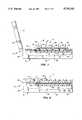
- FIGS. 3A and 3Bare enlarged scale cross-sectional views of the circled area "3" in FIG. 1 with the keyboard key cap members respectively in their extended use positions and their retracted storage/transport positions;
- FIG. 4is a schematic diagram of a control system, and a top plan view of an associated hollow fluid pressurizable pad structure, operative to selectively vary the keystroke force/distance characteristics of the keyboard using pressurized fluid forces imposed on the pad structure by the individual keys;
- FIG. 5is a graph illustrating a representative keystroke force/distance relationship provided to the keyboard by the FIG. 4 control system.
- FIG. 6is a diagram of an alternate embodiment of the portion of the FIG. 4 control system shown in the circled area "6" of FIG. 4.
- the present inventionprovides a portable computer, illustratively a notebook computer 10, having incorporated therein a specially designed collapsible keyboard structure 12 embodying principles of the present invention.
- Computer 10includes a hollow rectangular base housing 14 having a top horizontal side wall 16 with an opening 18 therein; a bottom horizontal side wall 20; front and rear vertical end walls 22,24; and a pair of opposite vertical side walls 26,28.
- Lid housing 30may upwardly pivoted to place the computer 10 in an open use orientation (FIG. 1) in which the top side 16 of the base housing 14 is exposed and the display screen 32 forwardly faces the user of the computer, or downwardly pivoted to place the computer 10 in a closed storage and transport orientation (FIG. 2) in which the lid housing extends across and covers the top side of the base housing 14.
- Suitable latch means(not shown) are provided to releasably retain the lid housing 30 in its FIG. 2 closed orientation.
- the collapsible keyboard structure 12extends across the opening 18 in the top side wall 16 of the base housing 14 and occupies only a relatively small upper portion of the interior 36 of the base housing.
- the keyboard structurebasically comprises a support structure which is representatively in the form of vertically spaced upper and lower support plates 37 and 38 that horizontally extend through a top side portion of the base housing 14 beneath its top wall opening 18, and a series of key switch assemblies each including a manually depressible key cap member 40 carried for vertical movement relative to the upper support plate 37 (as indicated by the arrows 42 in FIGS. 1 and 3A) through a total keystroke travel distance D (see FIG. 3A).
- each key cap member 40has a force transfer portion associated therewith, such force transfer portion representatively being in the form of a cylindrical plastic plunger member 44 axially projecting from the bottom side of the key cap member and slidably received in the interior of a vertically oriented tubular plastic barrel member 46 having an annular bottom end 48 suitably secured to the top side 49 of the upper support plate 37, and an annular top end 50.
- a circularly cross-sectioned opening 51is formed through the top support plate 37 and also slidably receives a longitudinal portion of the plunger 44.
- a bottom portion of the opening 51is diametrically enlarged, as at 52, to form a downwardly facing annular ledge 54 slightly inset from the bottom side of the top support plate 37.
- At the bottom end of the plunger 44is a relatively thin diametrically enlarged disc-shaped portion 56 which is upwardly receivable in the opening enlargement 52.
- the annular ledge 54functions as a stop surface to prevent the plunger's upward removal from its associated barrel member 46.
- a spline(not visible in FIGS.
- Each key cap member 40is vertically movable relative to the upper support plate 37 upon which it is mounted, through the total key stroke travel distance D, between (1) an upwardly extended use orientation shown in FIG. 3A (in which the enlarged lower plunger end portion 56 upwardly engages the annular interior ledge 54), and (2) a downwardly retracted storage and transport orientation on shown in FIG. 3B (in which the bottom side of the key cap member 40 downwardly engages the top end 50 of the barrel member 46).
- the key cap/plunger assembly 40,44reaches a vertically intermediate key switch activation or "firing" position indicated by the dashed line position of the plunger structure 44,56 shown in FIG. 3A.
- a position sensor 58is used to monitor the vertical position of the associated key cap member 40 and responsively output a position signal indicative of the sensed key cap stroke position.
- Each position sensor 58is representatively a photocell-type position sensor mounted on the upper side 49 of the top support plate 37 in a facing relationship with an underside portion of the associated key cap member 40.
- Each key switch assemblyalso includes a horizontally oriented hollow flexible pad member 60 which is sandwiched between the upper and lower support plates 37 and 38 as illustrated in FIGS. 1-3B.
- Pad member 60is adapted to receive a pressurized fluid (i.e., either a gas or liquid), and functions as later described herein to use an internal pressurized fluild force to yieldingly bias each key cap member 40, via its associated plunger 44) upwardly toward its FIG. 3A extended use position.
- a pressurized fluidi.e., either a gas or liquid
- the pad member 60comprises a main flexible body portion 62 whose interior 64 is representatively filled with pressurized air.
- a spaced series of separate subcompartments 66are formed in the body 62 and are positioned in underlying alignment with the bottom ends 56 of the key cap plungers 44.
- each subcompartment 66has a generally circular shape, a raised top side wall 68 which upwardly engages an associated overlying bottom plunger end 56, and a tubular side wall section 70 that seals the interior 66a of the subcompartment off from the main interior space 64 of the pad member body 62.
- an orifice opening 72is formed in each of the subcompartment side wall sections 70.
- the interior 64 of the pad body 62is preferably subdivided into separated zones 64a by means of body partition walls 73.
- Each zone 64acontains a group of the spaced subcompartments 66 therein.
- the interiorly pressurized pad subcompartments 66via the plungers 44 that they upwardly engage, serve to yieldingly bias the key caps 40 upwardly toward their FIG. 3A extended use positions.
- the associated subcompartment top side wall 68is forcibly deformed into the interior 66a of the subcompartment 66, thereby forcing air from the subcompartment interior 66a outwardly through the orifice 72 into the surrounding main interior portion 64 of the pad body 62.
- the key capWhen the key cap is released, pressurized air in the main pad interior space 64 flows back into the interior 66a of the subcompartment 66, via the sidewall section orifice 72, to cause the subcompartment top side wall 68 to again resiliently return the key cap 40 to its FIG. 3A upwardly extended use position.
- the key caps 40may be collapsed to their FIG. 3B retracted storage and transport positions by, for example, closing the computer lid housing 30 against the top side of the key cap members 40 as shown in FIG. 2.
- Key control system 74also includes a controller representatively in the form of a microprocessor 76, and a fluid pump representatively in the form of an air pump 78 having a variable speed electric drive motor 80.
- the outlet 82 of the pump 78is coupled to a fluid supply conduit 84 communicated with the pad zone interior spaces 64a via branch conduit lines 84a. Operation of the pump 78 serves to variably pressurize the pad interior spaces 64a and, via the orifices 72, the interiors 66a of the spaced pad subcompartments 66 as well.
- the variable speed pump motor 80is coupled to the microprocessor 76 by an electrical signal lead 86.
- a fluid conduit branch line 84bis connected to the inlet of a pressure-to-electric transducer 88 having an electrical output lead 90 connected to the microprocessor 76.
- a pressure relief valve 92is connected to the supply conduit 84.
- the valve 92Upon receipt of an appropriate control signal 94 (generated, for example, when the computer is turned off), the valve 92 is operative to bleed air 96 from the conduit 84, and thus the pad interior zones 64a, to thereby permit the key cap members 40 to be collapsed to their retracted storage and transport positions as previously described above.
- the position sensors 58output to the microprocessor 76 vertical key position signals S 1 -S N corresponding to their associated key cap members.
- the microprocessor 76automatically reacts to the related magnitudes of the key position signals S 1 -S N by responsively outputting the indicated key activation signals A 1 -A N which may be utilized in a generally conventional manner to cause the computer to carry out the command associated with the activation of the given key.
- the microprocessor 76is preferably programmed to receive one of a plurality (representatively three) of mutually different user-selected desired keystroke force/travel characteristic signals FT 1 , FT 2 and FT 3 .
- the user-selected input signal FT 1could be the key force/travel relationship graphically depicted by the solid and dashed lines in the graph in FIG. 5 wherein the solid line represents the selected key force/travel relationship during the downward activation stroke of a key, and the dashed line represents the hysteresis-reduced upward return force/travel characteristics of the key.
- the associated key cap plunger 44forces air out of its underlying pad subcompartment 66 into its associated pad interior zone 64a (see FIG. 4), thereby increasing the air pressure therein and correspondingly increasing the pressure within the fluid supply conduit 84.
- the key cap memberis released, thereby permitting pressurized air to re-enter its compartment 66, the pressure in the associated pad interior zone 64a decreases.
- the microprocessor 76In response to receipt of a selected one of the keystroke force/travel input signals FT 1 -FT 3 the microprocessor 76 automatically varies the magnitude of the voltage transmitted to the variable speed pump motor 80 via lead 86 to cause the pump 78 to vary the fluid pressure within the pad 60 (as sensed by the transducer 88 and reflected in the magnitude of microprocessor-received output signal 90) as a function of the sensed magnitudes of the received key position signals S 1 -S N to maintain the keystroke force/travel relationship (for example, the previously described solid and dashed line curves in the FIG. 5 graph) associated with the particular user-selected input signal FT 1 , FT 2 or FT 3 as the case may be.
- the keystroke force/travel relationshipfor example, the previously described solid and dashed line curves in the FIG. 5 graph
- control system 74has been described as utilizing a pressurizable gas (e.g., air) in the pad 60, a liquid such as water could be used instead. This could provide the additional advantage of being able to place the liquid-filled pad 60 against a heat-generating computer component such as a processor and use the pad as a heat receiving and spreading device in addition to its key-controlling function.
- a pressurizable gase.g., air
- a simple modificationcan be made to the control system 74 as schematically depicted in FIG. 6.
- the control system 74when liquid is to be utilized a reservoir structure 104 s secured to the air pump outlet 82, the reservoir structure having a flexible diaphragm member 106 extending across its interior with air 96 being disposed on the right side of the diaphragm 106, and the system liquid 108 (for example, water) being disposed on the left side of the diaphragm 106.
- the pump 78During operation of the pump 78, its discharge air pressure leftwardly flexes the diaphragm 106 to its dotted line position in FIG. 6 to thereby variably pressurize the liquid in the pad 60 as a function of the varied speed of the air pump motor 80.
- the pump 78When the pump 78 is turned off (for example, when the computer is turned off), the air pressure on the right side of the diaphragm 106 is relieved, thereby permitting the diaphragm 106 to rightwardly return to its solid line relaxed position. This, in turn, reduces the liquid pressure in the pad 60 and permits the key cap members 40 to be collapsed to their retracted storage and transport orientations as previously described in conjunction with the air filled pad 60.
- the present inventionthus provides a computer keyboard in which the individual key switch assemblies (1) are collapsible to reduce the thickness of the keyboard with the computer in a storage/transport orientation, and (2) have selectively adjustable keystroke force/travel characteristics to accommodate a variety of user keyboard "feel" preferences.
- the principles of this inventionare not limited to either the computer or keyboard arenas.
- the key switch assemblies and related control system representatively illustrated and described hereincan also be advantageously utilized in keyboards of other electronic devices, or in a variety of manually depressible switch devices wholly unrelated to keyboards, if desired.
Landscapes
- Engineering & Computer Science (AREA)
- Computer Hardware Design (AREA)
- Theoretical Computer Science (AREA)
- Physics & Mathematics (AREA)
- Human Computer Interaction (AREA)
- General Engineering & Computer Science (AREA)
- General Physics & Mathematics (AREA)
- Mathematical Physics (AREA)
- Input From Keyboards Or The Like (AREA)
- Push-Button Switches (AREA)
Abstract
Description
Claims (37)
Priority Applications (1)
| Application Number | Priority Date | Filing Date | Title |
|---|---|---|---|
| US08/769,796US5742242A (en) | 1996-12-19 | 1996-12-19 | Keyboard using pressurized fluid to generate key stroke characteristics |
Applications Claiming Priority (1)
| Application Number | Priority Date | Filing Date | Title |
|---|---|---|---|
| US08/769,796US5742242A (en) | 1996-12-19 | 1996-12-19 | Keyboard using pressurized fluid to generate key stroke characteristics |
Publications (1)
| Publication Number | Publication Date |
|---|---|
| US5742242Atrue US5742242A (en) | 1998-04-21 |
Family
ID=25086526
Family Applications (1)
| Application Number | Title | Priority Date | Filing Date |
|---|---|---|---|
| US08/769,796Expired - LifetimeUS5742242A (en) | 1996-12-19 | 1996-12-19 | Keyboard using pressurized fluid to generate key stroke characteristics |
Country Status (1)
| Country | Link |
|---|---|
| US (1) | US5742242A (en) |
Cited By (47)
| Publication number | Priority date | Publication date | Assignee | Title |
|---|---|---|---|---|
| US5879088A (en)* | 1997-11-24 | 1999-03-09 | Key Tronic Corporation | Computer keyboard with adjustable force keystroke feature using air pressure |
| WO2001050608A1 (en)* | 2000-01-03 | 2001-07-12 | Levenson David J | Adjustable ergonomic keyboard for use with stationary palm and elements thereof |
| US20020163451A1 (en)* | 2001-05-03 | 2002-11-07 | Johnston Raymond Patrick | Liquid proof switch array |
| US20030184991A1 (en)* | 2002-03-27 | 2003-10-02 | Johnston Raymond P. | Lighted fastening structure |
| US6690360B2 (en) | 2001-05-03 | 2004-02-10 | 3M Innovative Properties Company | Liquid proof switch array |
| US6740832B2 (en) | 2002-03-27 | 2004-05-25 | 3M Innovative Properties Company | Apparatus exhibiting tactile feel |
| US20040239616A1 (en)* | 2003-05-28 | 2004-12-02 | Collins Ryan V. | Methods and apparatus for receiving user input via time domain reflectometry |
| US20050083215A1 (en)* | 1993-07-29 | 2005-04-21 | Crowley Robert J. | Keyboard with keys for moving cursor |
| US6887004B1 (en)* | 2000-03-09 | 2005-05-03 | Active Input Solutions, Llc | Keyboard support platform |
| WO2005117439A3 (en)* | 2004-05-25 | 2006-05-04 | Inputive Corp | Method and device for providing input to a computer system |
| US20080068224A1 (en)* | 2004-06-28 | 2008-03-20 | Sensitivity Limited | Actuation Apparatus |
| US20100328251A1 (en)* | 2009-06-30 | 2010-12-30 | Microsoft Corporation | Tactile feedback display screen overlay |
| US20110107958A1 (en)* | 2009-11-12 | 2011-05-12 | Apple Inc. | Input devices and methods of operation |
| US20110167993A1 (en)* | 2010-01-14 | 2011-07-14 | Hon Hai Precision Industry Co., Ltd. | Keyboard having micro-electro-mechanical sensor |
| CN102389317A (en)* | 2011-07-14 | 2012-03-28 | 哈尔滨工业大学 | Real-time keystroke-pressure acquisition system |
| US20140091857A1 (en)* | 2012-09-28 | 2014-04-03 | Apple Inc. | Ultra Low Travel Keyboard |
| TWI493585B (en)* | 2010-04-01 | 2015-07-21 | Hon Hai Prec Ind Co Ltd | Keyboard |
| US9202355B2 (en) | 2009-09-30 | 2015-12-01 | Apple Inc. | Self adapting haptic device |
| US9317118B2 (en) | 2013-10-22 | 2016-04-19 | Apple Inc. | Touch surface for simulating materials |
| US9501912B1 (en) | 2014-01-27 | 2016-11-22 | Apple Inc. | Haptic feedback device with a rotating mass of variable eccentricity |
| US9564029B2 (en) | 2014-09-02 | 2017-02-07 | Apple Inc. | Haptic notifications |
| US9608506B2 (en) | 2014-06-03 | 2017-03-28 | Apple Inc. | Linear actuator |
| US9652040B2 (en) | 2013-08-08 | 2017-05-16 | Apple Inc. | Sculpted waveforms with no or reduced unforced response |
| US9779888B2 (en) | 2011-12-21 | 2017-10-03 | Apple Inc. | Keyboard with position sensing mechanism |
| US9779592B1 (en) | 2013-09-26 | 2017-10-03 | Apple Inc. | Geared haptic feedback element |
| US9886093B2 (en) | 2013-09-27 | 2018-02-06 | Apple Inc. | Band with haptic actuators |
| US9928950B2 (en) | 2013-09-27 | 2018-03-27 | Apple Inc. | Polarized magnetic actuators for haptic response |
| US10013058B2 (en) | 2010-09-21 | 2018-07-03 | Apple Inc. | Touch-based user interface with haptic feedback |
| US10039080B2 (en) | 2016-03-04 | 2018-07-31 | Apple Inc. | Situationally-aware alerts |
| US10068727B2 (en) | 2015-08-04 | 2018-09-04 | Apple Inc. | Key surface lighting |
| US10109436B2 (en) | 2017-02-02 | 2018-10-23 | Acer Incorporated | Keyboard module and electronic device using the same |
| US10120446B2 (en) | 2010-11-19 | 2018-11-06 | Apple Inc. | Haptic input device |
| US10126817B2 (en) | 2013-09-29 | 2018-11-13 | Apple Inc. | Devices and methods for creating haptic effects |
| US10236760B2 (en) | 2013-09-30 | 2019-03-19 | Apple Inc. | Magnetic actuators for haptic response |
| US10268272B2 (en) | 2016-03-31 | 2019-04-23 | Apple Inc. | Dampening mechanical modes of a haptic actuator using a delay |
| US10276001B2 (en) | 2013-12-10 | 2019-04-30 | Apple Inc. | Band attachment mechanism with haptic response |
| US10353467B2 (en) | 2015-03-06 | 2019-07-16 | Apple Inc. | Calibration of haptic devices |
| US10481691B2 (en) | 2015-04-17 | 2019-11-19 | Apple Inc. | Contracting and elongating materials for providing input and output for an electronic device |
| US10545604B2 (en) | 2014-04-21 | 2020-01-28 | Apple Inc. | Apportionment of forces for multi-touch input devices of electronic devices |
| US20200050284A1 (en)* | 2016-10-25 | 2020-02-13 | Topre Corporation | Keyboard threshold change apparatus and keyboard |
| US10566888B2 (en) | 2015-09-08 | 2020-02-18 | Apple Inc. | Linear actuators for use in electronic devices |
| US10599223B1 (en) | 2018-09-28 | 2020-03-24 | Apple Inc. | Button providing force sensing and/or haptic output |
| US10622538B2 (en) | 2017-07-18 | 2020-04-14 | Apple Inc. | Techniques for providing a haptic output and sensing a haptic input using a piezoelectric body |
| US10691211B2 (en) | 2018-09-28 | 2020-06-23 | Apple Inc. | Button providing force sensing and/or haptic output |
| US11380470B2 (en) | 2019-09-24 | 2022-07-05 | Apple Inc. | Methods to control force in reluctance actuators based on flux related parameters |
| US11809631B2 (en) | 2021-09-21 | 2023-11-07 | Apple Inc. | Reluctance haptic engine for an electronic device |
| US11977683B2 (en) | 2021-03-12 | 2024-05-07 | Apple Inc. | Modular systems configured to provide localized haptic feedback using inertial actuators |
Citations (5)
| Publication number | Priority date | Publication date | Assignee | Title |
|---|---|---|---|---|
| US3603983A (en)* | 1969-07-23 | 1971-09-07 | Northern Electric Co | Mechanical-electrical code generating device employing fluid switching |
| US4109118A (en)* | 1976-09-01 | 1978-08-22 | Victor Kley | Keyswitch pad |
| US4795888A (en)* | 1985-04-29 | 1989-01-03 | A & K Macfarlane Pty. Ltd. | Variable keystroke pressure apparatus |
| US5459461A (en)* | 1993-07-29 | 1995-10-17 | Crowley; Robert J. | Inflatable keyboard |
| US5595449A (en)* | 1995-12-21 | 1997-01-21 | Delco Electronics Corporation | Inflatable keyboard |
- 1996
- 1996-12-19USUS08/769,796patent/US5742242A/ennot_activeExpired - Lifetime
Patent Citations (6)
| Publication number | Priority date | Publication date | Assignee | Title |
|---|---|---|---|---|
| US3603983A (en)* | 1969-07-23 | 1971-09-07 | Northern Electric Co | Mechanical-electrical code generating device employing fluid switching |
| US4109118A (en)* | 1976-09-01 | 1978-08-22 | Victor Kley | Keyswitch pad |
| US4795888A (en)* | 1985-04-29 | 1989-01-03 | A & K Macfarlane Pty. Ltd. | Variable keystroke pressure apparatus |
| US5459461A (en)* | 1993-07-29 | 1995-10-17 | Crowley; Robert J. | Inflatable keyboard |
| US5648771A (en)* | 1993-07-29 | 1997-07-15 | Halgren; Donald N. | Wrist rest bag for flexible keyboard |
| US5595449A (en)* | 1995-12-21 | 1997-01-21 | Delco Electronics Corporation | Inflatable keyboard |
Cited By (73)
| Publication number | Priority date | Publication date | Assignee | Title |
|---|---|---|---|---|
| US7589712B2 (en)* | 1993-07-29 | 2009-09-15 | Crowley Robert J | Keyboard with keys for moving cursor |
| US20050083215A1 (en)* | 1993-07-29 | 2005-04-21 | Crowley Robert J. | Keyboard with keys for moving cursor |
| US5879088A (en)* | 1997-11-24 | 1999-03-09 | Key Tronic Corporation | Computer keyboard with adjustable force keystroke feature using air pressure |
| WO2001050608A1 (en)* | 2000-01-03 | 2001-07-12 | Levenson David J | Adjustable ergonomic keyboard for use with stationary palm and elements thereof |
| US20030011503A1 (en)* | 2000-01-03 | 2003-01-16 | Levenson David J. | Adjustable ergonomic keyboard for use with stationary palm and elements thereof |
| US7324019B2 (en) | 2000-01-03 | 2008-01-29 | Levenson David J | Adjustable ergonomic keyboard for use with stationary palm and elements thereof |
| US6887004B1 (en)* | 2000-03-09 | 2005-05-03 | Active Input Solutions, Llc | Keyboard support platform |
| US20020163451A1 (en)* | 2001-05-03 | 2002-11-07 | Johnston Raymond Patrick | Liquid proof switch array |
| US6690360B2 (en) | 2001-05-03 | 2004-02-10 | 3M Innovative Properties Company | Liquid proof switch array |
| US7091952B2 (en) | 2001-05-03 | 2006-08-15 | 3M Innovative Properties Company | Liquid proof switch array |
| US20030184991A1 (en)* | 2002-03-27 | 2003-10-02 | Johnston Raymond P. | Lighted fastening structure |
| US6827459B2 (en) | 2002-03-27 | 2004-12-07 | 3M Innovative Properties Company | Lighted fastening structure |
| US6740832B2 (en) | 2002-03-27 | 2004-05-25 | 3M Innovative Properties Company | Apparatus exhibiting tactile feel |
| US20040239616A1 (en)* | 2003-05-28 | 2004-12-02 | Collins Ryan V. | Methods and apparatus for receiving user input via time domain reflectometry |
| WO2005117439A3 (en)* | 2004-05-25 | 2006-05-04 | Inputive Corp | Method and device for providing input to a computer system |
| US20080068224A1 (en)* | 2004-06-28 | 2008-03-20 | Sensitivity Limited | Actuation Apparatus |
| US20100328251A1 (en)* | 2009-06-30 | 2010-12-30 | Microsoft Corporation | Tactile feedback display screen overlay |
| US9024908B2 (en)* | 2009-06-30 | 2015-05-05 | Microsoft Technology Licensing, Llc | Tactile feedback display screen overlay |
| US11605273B2 (en) | 2009-09-30 | 2023-03-14 | Apple Inc. | Self-adapting electronic device |
| US10475300B2 (en) | 2009-09-30 | 2019-11-12 | Apple Inc. | Self adapting haptic device |
| US9934661B2 (en) | 2009-09-30 | 2018-04-03 | Apple Inc. | Self adapting haptic device |
| US9640048B2 (en) | 2009-09-30 | 2017-05-02 | Apple Inc. | Self adapting haptic device |
| US11043088B2 (en) | 2009-09-30 | 2021-06-22 | Apple Inc. | Self adapting haptic device |
| US12094328B2 (en) | 2009-09-30 | 2024-09-17 | Apple Inc. | Device having a camera used to detect visual cues that activate a function of the device |
| US9202355B2 (en) | 2009-09-30 | 2015-12-01 | Apple Inc. | Self adapting haptic device |
| US20110107958A1 (en)* | 2009-11-12 | 2011-05-12 | Apple Inc. | Input devices and methods of operation |
| US20110167993A1 (en)* | 2010-01-14 | 2011-07-14 | Hon Hai Precision Industry Co., Ltd. | Keyboard having micro-electro-mechanical sensor |
| TWI493585B (en)* | 2010-04-01 | 2015-07-21 | Hon Hai Prec Ind Co Ltd | Keyboard |
| US10013058B2 (en) | 2010-09-21 | 2018-07-03 | Apple Inc. | Touch-based user interface with haptic feedback |
| US10120446B2 (en) | 2010-11-19 | 2018-11-06 | Apple Inc. | Haptic input device |
| CN102389317A (en)* | 2011-07-14 | 2012-03-28 | 哈尔滨工业大学 | Real-time keystroke-pressure acquisition system |
| CN102389317B (en)* | 2011-07-14 | 2016-02-10 | 哈尔滨工业大学 | A kind of real-time keystroke-pressure acquisition system |
| US9779888B2 (en) | 2011-12-21 | 2017-10-03 | Apple Inc. | Keyboard with position sensing mechanism |
| US9997306B2 (en) | 2012-09-28 | 2018-06-12 | Apple Inc. | Ultra low travel keyboard |
| US9911553B2 (en) | 2012-09-28 | 2018-03-06 | Apple Inc. | Ultra low travel keyboard |
| US9178509B2 (en)* | 2012-09-28 | 2015-11-03 | Apple Inc. | Ultra low travel keyboard |
| US20140091857A1 (en)* | 2012-09-28 | 2014-04-03 | Apple Inc. | Ultra Low Travel Keyboard |
| US9652040B2 (en) | 2013-08-08 | 2017-05-16 | Apple Inc. | Sculpted waveforms with no or reduced unforced response |
| US9779592B1 (en) | 2013-09-26 | 2017-10-03 | Apple Inc. | Geared haptic feedback element |
| US9886093B2 (en) | 2013-09-27 | 2018-02-06 | Apple Inc. | Band with haptic actuators |
| US9928950B2 (en) | 2013-09-27 | 2018-03-27 | Apple Inc. | Polarized magnetic actuators for haptic response |
| US10126817B2 (en) | 2013-09-29 | 2018-11-13 | Apple Inc. | Devices and methods for creating haptic effects |
| US10651716B2 (en) | 2013-09-30 | 2020-05-12 | Apple Inc. | Magnetic actuators for haptic response |
| US10236760B2 (en) | 2013-09-30 | 2019-03-19 | Apple Inc. | Magnetic actuators for haptic response |
| US10459521B2 (en) | 2013-10-22 | 2019-10-29 | Apple Inc. | Touch surface for simulating materials |
| US9317118B2 (en) | 2013-10-22 | 2016-04-19 | Apple Inc. | Touch surface for simulating materials |
| US10276001B2 (en) | 2013-12-10 | 2019-04-30 | Apple Inc. | Band attachment mechanism with haptic response |
| US9501912B1 (en) | 2014-01-27 | 2016-11-22 | Apple Inc. | Haptic feedback device with a rotating mass of variable eccentricity |
| US10545604B2 (en) | 2014-04-21 | 2020-01-28 | Apple Inc. | Apportionment of forces for multi-touch input devices of electronic devices |
| US10069392B2 (en) | 2014-06-03 | 2018-09-04 | Apple Inc. | Linear vibrator with enclosed mass assembly structure |
| US9608506B2 (en) | 2014-06-03 | 2017-03-28 | Apple Inc. | Linear actuator |
| US9830782B2 (en) | 2014-09-02 | 2017-11-28 | Apple Inc. | Haptic notifications |
| US10490035B2 (en) | 2014-09-02 | 2019-11-26 | Apple Inc. | Haptic notifications |
| US9564029B2 (en) | 2014-09-02 | 2017-02-07 | Apple Inc. | Haptic notifications |
| US10353467B2 (en) | 2015-03-06 | 2019-07-16 | Apple Inc. | Calibration of haptic devices |
| US10481691B2 (en) | 2015-04-17 | 2019-11-19 | Apple Inc. | Contracting and elongating materials for providing input and output for an electronic device |
| US11402911B2 (en) | 2015-04-17 | 2022-08-02 | Apple Inc. | Contracting and elongating materials for providing input and output for an electronic device |
| US10068727B2 (en) | 2015-08-04 | 2018-09-04 | Apple Inc. | Key surface lighting |
| US10566888B2 (en) | 2015-09-08 | 2020-02-18 | Apple Inc. | Linear actuators for use in electronic devices |
| US10609677B2 (en) | 2016-03-04 | 2020-03-31 | Apple Inc. | Situationally-aware alerts |
| US10039080B2 (en) | 2016-03-04 | 2018-07-31 | Apple Inc. | Situationally-aware alerts |
| US10809805B2 (en) | 2016-03-31 | 2020-10-20 | Apple Inc. | Dampening mechanical modes of a haptic actuator using a delay |
| US10268272B2 (en) | 2016-03-31 | 2019-04-23 | Apple Inc. | Dampening mechanical modes of a haptic actuator using a delay |
| US10684700B2 (en)* | 2016-10-25 | 2020-06-16 | Topre Corporation | Keyboard threshold change apparatus and keyboard |
| US20200050284A1 (en)* | 2016-10-25 | 2020-02-13 | Topre Corporation | Keyboard threshold change apparatus and keyboard |
| US10109436B2 (en) | 2017-02-02 | 2018-10-23 | Acer Incorporated | Keyboard module and electronic device using the same |
| US10622538B2 (en) | 2017-07-18 | 2020-04-14 | Apple Inc. | Techniques for providing a haptic output and sensing a haptic input using a piezoelectric body |
| US10691211B2 (en) | 2018-09-28 | 2020-06-23 | Apple Inc. | Button providing force sensing and/or haptic output |
| US10599223B1 (en) | 2018-09-28 | 2020-03-24 | Apple Inc. | Button providing force sensing and/or haptic output |
| US11380470B2 (en) | 2019-09-24 | 2022-07-05 | Apple Inc. | Methods to control force in reluctance actuators based on flux related parameters |
| US11763971B2 (en) | 2019-09-24 | 2023-09-19 | Apple Inc. | Methods to control force in reluctance actuators based on flux related parameters |
| US11977683B2 (en) | 2021-03-12 | 2024-05-07 | Apple Inc. | Modular systems configured to provide localized haptic feedback using inertial actuators |
| US11809631B2 (en) | 2021-09-21 | 2023-11-07 | Apple Inc. | Reluctance haptic engine for an electronic device |
Similar Documents
| Publication | Publication Date | Title |
|---|---|---|
| US5742242A (en) | Keyboard using pressurized fluid to generate key stroke characteristics | |
| US5587875A (en) | Collapsible notebook computer keyboard structure with horizontally and downwardly shiftable key return domes | |
| US5532904A (en) | Collapsible keyboard structure for a notebook computer, responsive to opening and closing of the computer's lid | |
| US5590020A (en) | Collapsible notebook computer keyboard structure with resiliently deflectable key cap skirts | |
| US5602715A (en) | Collapsible keyboard structure for a notebook computer, responsive to opening and closing of the computer's lid via relatively shiftable key support member and shift member | |
| US5621610A (en) | Collapsible computer keyboard structure with associated collapsible pointing stick | |
| TW505572B (en) | Ink container with pressure regulation device | |
| US5212473A (en) | Membrane keyboard and method of using same | |
| US5278371A (en) | Keyswitch assembly with support mechanism coupled to support plate beneath printed circuit board | |
| KR0141518B1 (en) | Method and apparatus for extending the environmental range of an ink jet print cartridge | |
| US5575576A (en) | Keyboard | |
| US5879088A (en) | Computer keyboard with adjustable force keystroke feature using air pressure | |
| US5717429A (en) | Low profile, light weight keyboard | |
| US4517421A (en) | Resilient deformable keyboard | |
| US5933320A (en) | Computer having a collapsible keyboard structure | |
| TW460826B (en) | Thin film switch circuit board having gas chamber for pressure adjustment | |
| AU1207392A (en) | Membrane keyboard and method of using same | |
| US5186700A (en) | Pedaling exercise device | |
| US5677826A (en) | Double spring collapsible keyboard structure for a notebook computer, responsive to opening and closing of the computer's lid via relatively shiftable key support structure and shift member | |
| US20180218858A1 (en) | Keyboard module and electronic device using the same | |
| US5694124A (en) | Portable computer with integrated circuit board and keyboard | |
| US6137676A (en) | Collapsible keyboard mechanism with integrated LCD display | |
| US5197178A (en) | Sealed computer terminal keyboard | |
| US20180122599A1 (en) | Liftable keyboard | |
| CN111852827B (en) | Electric air pump |
Legal Events
| Date | Code | Title | Description |
|---|---|---|---|
| AS | Assignment | Owner name:COMPAQ COMPUTER CORPORATION, TEXAS Free format text:ASSIGNMENT OF ASSIGNORS INTEREST;ASSIGNOR:SELLERS, CHARLES A.;REEL/FRAME:008362/0096 Effective date:19961212 | |
| FEPP | Fee payment procedure | Free format text:PAYOR NUMBER ASSIGNED (ORIGINAL EVENT CODE: ASPN); ENTITY STATUS OF PATENT OWNER: LARGE ENTITY | |
| STCF | Information on status: patent grant | Free format text:PATENTED CASE | |
| FPAY | Fee payment | Year of fee payment:4 | |
| AS | Assignment | Owner name:COMPAQ INFORMATION TECHNOLOGIES GROUP, L.P., TEXAS Free format text:ASSIGNMENT OF ASSIGNORS INTEREST;ASSIGNOR:COMPAQ COMPUTER CORPORATION;REEL/FRAME:012418/0222 Effective date:20010620 | |
| AS | Assignment | Owner name:HEWLETT-PACKARD DEVELOPMENT COMPANY, L.P., TEXAS Free format text:CHANGE OF NAME;ASSIGNOR:COMPAQ INFORMATION TECHNOLOGIES GROUP, LP;REEL/FRAME:015000/0305 Effective date:20021001 | |
| FPAY | Fee payment | Year of fee payment:8 | |
| FEPP | Fee payment procedure | Free format text:PAYER NUMBER DE-ASSIGNED (ORIGINAL EVENT CODE: RMPN); ENTITY STATUS OF PATENT OWNER: LARGE ENTITY Free format text:PAYOR NUMBER ASSIGNED (ORIGINAL EVENT CODE: ASPN); ENTITY STATUS OF PATENT OWNER: LARGE ENTITY | |
| FPAY | Fee payment | Year of fee payment:12 |