US5741279A - Endoscopic suture system - Google Patents
Endoscopic suture systemDownload PDFInfo
- Publication number
- US5741279A US5741279AUS08/743,886US74388696AUS5741279AUS 5741279 AUS5741279 AUS 5741279AUS 74388696 AUS74388696 AUS 74388696AUS 5741279 AUS5741279 AUS 5741279A
- Authority
- US
- United States
- Prior art keywords
- needle
- suture
- driver
- tissue
- flexible
- Prior art date
- Legal status (The legal status is an assumption and is not a legal conclusion. Google has not performed a legal analysis and makes no representation as to the accuracy of the status listed.)
- Expired - Lifetime
Links
Images


Classifications
- A—HUMAN NECESSITIES
- A61—MEDICAL OR VETERINARY SCIENCE; HYGIENE
- A61B—DIAGNOSIS; SURGERY; IDENTIFICATION
- A61B17/00—Surgical instruments, devices or methods
- A61B17/04—Surgical instruments, devices or methods for suturing wounds; Holders or packages for needles or suture materials
- A61B17/06—Needles ; Sutures; Needle-suture combinations; Holders or packages for needles or suture materials
- A61B17/062—Needle manipulators
- A61B17/0625—Needle manipulators the needle being specially adapted to interact with the manipulator, e.g. being ridged to snap fit in a hole of the manipulator
- A—HUMAN NECESSITIES
- A61—MEDICAL OR VETERINARY SCIENCE; HYGIENE
- A61B—DIAGNOSIS; SURGERY; IDENTIFICATION
- A61B17/00—Surgical instruments, devices or methods
- A61B17/04—Surgical instruments, devices or methods for suturing wounds; Holders or packages for needles or suture materials
- A61B17/0469—Suturing instruments for use in minimally invasive surgery, e.g. endoscopic surgery
- A—HUMAN NECESSITIES
- A61—MEDICAL OR VETERINARY SCIENCE; HYGIENE
- A61B—DIAGNOSIS; SURGERY; IDENTIFICATION
- A61B17/00—Surgical instruments, devices or methods
- A61B17/04—Surgical instruments, devices or methods for suturing wounds; Holders or packages for needles or suture materials
- A61B17/0482—Needle or suture guides
- A—HUMAN NECESSITIES
- A61—MEDICAL OR VETERINARY SCIENCE; HYGIENE
- A61B—DIAGNOSIS; SURGERY; IDENTIFICATION
- A61B17/00—Surgical instruments, devices or methods
- A61B17/04—Surgical instruments, devices or methods for suturing wounds; Holders or packages for needles or suture materials
- A61B17/06—Needles ; Sutures; Needle-suture combinations; Holders or packages for needles or suture materials
- A61B17/06066—Needles, e.g. needle tip configurations
- A—HUMAN NECESSITIES
- A61—MEDICAL OR VETERINARY SCIENCE; HYGIENE
- A61B—DIAGNOSIS; SURGERY; IDENTIFICATION
- A61B17/00—Surgical instruments, devices or methods
- A61B17/0057—Implements for plugging an opening in the wall of a hollow or tubular organ, e.g. for sealing a vessel puncture or closing a cardiac septal defect
- A—HUMAN NECESSITIES
- A61—MEDICAL OR VETERINARY SCIENCE; HYGIENE
- A61B—DIAGNOSIS; SURGERY; IDENTIFICATION
- A61B17/00—Surgical instruments, devices or methods
- A61B17/04—Surgical instruments, devices or methods for suturing wounds; Holders or packages for needles or suture materials
- A61B17/06—Needles ; Sutures; Needle-suture combinations; Holders or packages for needles or suture materials
- A61B17/062—Needle manipulators
- A—HUMAN NECESSITIES
- A61—MEDICAL OR VETERINARY SCIENCE; HYGIENE
- A61B—DIAGNOSIS; SURGERY; IDENTIFICATION
- A61B17/00—Surgical instruments, devices or methods
- A61B17/28—Surgical forceps
- A61B17/29—Forceps for use in minimally invasive surgery
- A61B17/2909—Handles
- A—HUMAN NECESSITIES
- A61—MEDICAL OR VETERINARY SCIENCE; HYGIENE
- A61B—DIAGNOSIS; SURGERY; IDENTIFICATION
- A61B17/00—Surgical instruments, devices or methods
- A61B17/0057—Implements for plugging an opening in the wall of a hollow or tubular organ, e.g. for sealing a vessel puncture or closing a cardiac septal defect
- A61B2017/00637—Implements for plugging an opening in the wall of a hollow or tubular organ, e.g. for sealing a vessel puncture or closing a cardiac septal defect for sealing trocar wounds through abdominal wall
- A—HUMAN NECESSITIES
- A61—MEDICAL OR VETERINARY SCIENCE; HYGIENE
- A61B—DIAGNOSIS; SURGERY; IDENTIFICATION
- A61B17/00—Surgical instruments, devices or methods
- A61B17/0057—Implements for plugging an opening in the wall of a hollow or tubular organ, e.g. for sealing a vessel puncture or closing a cardiac septal defect
- A61B2017/00646—Type of implements
- A61B2017/00663—Type of implements the implement being a suture
- A—HUMAN NECESSITIES
- A61—MEDICAL OR VETERINARY SCIENCE; HYGIENE
- A61B—DIAGNOSIS; SURGERY; IDENTIFICATION
- A61B17/00—Surgical instruments, devices or methods
- A61B17/04—Surgical instruments, devices or methods for suturing wounds; Holders or packages for needles or suture materials
- A61B17/0469—Suturing instruments for use in minimally invasive surgery, e.g. endoscopic surgery
- A61B2017/047—Suturing instruments for use in minimally invasive surgery, e.g. endoscopic surgery having at least one proximally pointing needle located at the distal end of the instrument, e.g. for suturing trocar puncture wounds starting from inside the body
- A—HUMAN NECESSITIES
- A61—MEDICAL OR VETERINARY SCIENCE; HYGIENE
- A61B—DIAGNOSIS; SURGERY; IDENTIFICATION
- A61B17/00—Surgical instruments, devices or methods
- A61B17/04—Surgical instruments, devices or methods for suturing wounds; Holders or packages for needles or suture materials
- A61B17/0469—Suturing instruments for use in minimally invasive surgery, e.g. endoscopic surgery
- A61B2017/0472—Multiple-needled, e.g. double-needled, instruments
- A—HUMAN NECESSITIES
- A61—MEDICAL OR VETERINARY SCIENCE; HYGIENE
- A61B—DIAGNOSIS; SURGERY; IDENTIFICATION
- A61B17/00—Surgical instruments, devices or methods
- A61B17/04—Surgical instruments, devices or methods for suturing wounds; Holders or packages for needles or suture materials
- A61B17/0469—Suturing instruments for use in minimally invasive surgery, e.g. endoscopic surgery
- A61B2017/0474—Knot pushers
- A—HUMAN NECESSITIES
- A61—MEDICAL OR VETERINARY SCIENCE; HYGIENE
- A61B—DIAGNOSIS; SURGERY; IDENTIFICATION
- A61B17/00—Surgical instruments, devices or methods
- A61B17/04—Surgical instruments, devices or methods for suturing wounds; Holders or packages for needles or suture materials
- A61B17/0469—Suturing instruments for use in minimally invasive surgery, e.g. endoscopic surgery
- A61B2017/0479—Packages or dispensers for MIS suturing instruments
- A—HUMAN NECESSITIES
- A61—MEDICAL OR VETERINARY SCIENCE; HYGIENE
- A61B—DIAGNOSIS; SURGERY; IDENTIFICATION
- A61B17/00—Surgical instruments, devices or methods
- A61B17/04—Surgical instruments, devices or methods for suturing wounds; Holders or packages for needles or suture materials
- A61B17/06—Needles ; Sutures; Needle-suture combinations; Holders or packages for needles or suture materials
- A61B2017/06057—Double-armed sutures, i.e. sutures having a needle attached to each end
- A—HUMAN NECESSITIES
- A61—MEDICAL OR VETERINARY SCIENCE; HYGIENE
- A61B—DIAGNOSIS; SURGERY; IDENTIFICATION
- A61B17/00—Surgical instruments, devices or methods
- A61B17/28—Surgical forceps
- A61B17/29—Forceps for use in minimally invasive surgery
- A61B2017/2901—Details of shaft
Definitions
- the inventionrelates to devices for approximation, ligation and fixation of tissue using a suture, and particularly to the tissue separated by means of an endosurgical trocar being inserted into a body cavity, and to approximation, ligation, and fixation of tissue using endosurgical techniques.
- endosurgerymeans endoscopic surgery or surgery performed using an endoscope.
- the endoscopebecomes the surgeons' new eyes from which they operate.
- Operations using an endoscopeare significantly less invasive when compared to traditional open surgery. Patients usually return home the next day or in some cases the same day of the endosurgical procedure. This is in contrast to standard open surgical procedures where a large incision divides the muscle layers and allows the surgeon to directly visualize the operative area. Patients may stay in the hospital for 5 to 6 days or longer following open surgery. In addition, after endosurgical procedures, patients return to work within a few days versus the traditional 3 to 4 weeks at home following open surgery.
- trocarsAccess to the operative site using endosurgical or minimally invasive techniques is accomplished by inserting small tubes called trocars into a body cavity. These tubes have a diameter of, for example, between 3 mm and 30 mm and a length of about 150 mm (6 inches).
- a body cavityThrough these trocar tubes.
- Such an instrumentis disclosed by Mulhollan et al, U.S. Pat. No. 4,621,640 issued Nov. 11, 1986.
- Mulhollandescribes an instrument that may be used to hold and drive a needle, but makes no provision for retrieval of the needle from the body cavity, nor the completion of the suture by tying.
- Mulhollan's instrumentis limited in that the arc through which the needle must be driven is perpendicular to the axis of the device.
- Another such instrument intended for endoscopic useis described by Yoon, U.S. Pat. No. 4,935,027, issued Jun. 19, 1990.
- This instrumentuses oppositional hollow needles or tracks pushed through the tissue and coapted to create a tract through which the suture material is pushed. It is not clear how these curved tracks would be adapted to both be able to pierce the tissue planes illustrated, parallel to the tips of the tracks, and be curved toward each other to form the hollow tract.
- the invention herein describedmay be used for final closure of umbilical and secondary trocar puncture wounds in abdominal tissues including the fascia and other layers.
- the umbilical punctureis routinely a puncture site of 10 mm to 12 mm. Future procedures may require trocar puncture sites up to 18 mm and greater in size. Due to the large size of the puncture wound, it is important that the site be closed or approximated at the interior abdominal wall following removal of the large trocar cannula. An improper or non existent closure can lead to a herniation of the bowel and/or bowel obstruction.
- the present mode for closureis to reach down to the desired tissue layer with a pair of needle drivers holding a needle and suture material and secure a stitch. Many patients are obese and present considerable fat in this region.
- the abdominal wallmay be several inches thick, it is extremely difficult, tedious and time consuming to approximate the fascial tissues with a suture. Often times, following removal of a large trocar, the puncture site needs to be enlarged to accomplish this, thus negating some of the advantages of endoscopic surgery previously discussed.
- One of the embodiments described hereinmay be of particular advantage in performing a surgery for correction of female stress incontinence, which affects over 5 million women in the United States. Stress incontinence is caused when the structures defining the pelvic floor are altered by aging or disturbed by the process of childbirth or other trauma. These structures in the pelvic floor normally hold the urinary bladder such that maintenance of a volume of urine in the bladder is accomplished by a combination of muscle tone and bladder positioning.
- the classic open Burch suspension procedureis one such procedure and is a straightforward surgical treatment for correction of female stress incontinence.
- suturesare precisely placed in the wall of the vagina on each side of the urethra, with care being taken to avoid puncturing either the urethra or the mucosal layer of the vagina.
- These suturesare then looped through a ligament, called Cooper's ligament, which runs along the posterior ridge of the pubic bone.
- Cooper's ligamentwhich runs along the posterior ridge of the pubic bone.
- the laparoscopic approach to the Burch procedurehas all of the advantages described earlier with respect to post operative pain, hospital stay and recovery time. There are three difficulties associated with the laparoscopic approach; access, suture placement, and knot tying.
- the present inventionaddresses the problems surrounding the placement of the sutures in the appropriate structures and in the optimal position, and also addresses particular aspects of needle retrieval and knot tying when using endoscopic techniques.
- the suture and needle combinationis dropped in the body cavity, and the needle is then located and picked up and properly positioned in the needle holder jaws. This is a difficult and time consuming aspect of the current endoscopic technique for suturing.
- the needle carrying the suturemay then be driven by pronation of the wrist, causing rotation of the elongate shaft, and subsequent arcuate rotation of the semi-circular needle.
- this type of needle driveris that the needle may only be driven or rotated in a plane perpendicular to the axis of rotation, such axis being described by the elongate shaft and the position of the surgical trocar.
- the current endoscopic needle driverswill not allow the surgeon to swing the needle in an arc parallel to the trocar's axis.
- Thisis a severe limitation in the case of the laparoscopic Burch, because of the orientation of the anatomy relative to the planes of access.
- the vaginal wall and the Cooper's ligamentrequire the sutures to be placed in a orientation that makes the procedure extremely difficult and time consuming with the use of currently available instrumentation. It is also a limitation when attempting to ligate vessels, ligaments and other structures that run perpendicular to the axis of the operative trocar.
- the surgeonmust be able to retrieve the needle trailing the suture material back through the same surgical trocar through which the needle driver is placed. This allows a knot to be tied in the suture outside of the body, and pushed down the trocar to the structure being sutured.
- the needle drivermust be able to retrieve the needle and bring the needle trailing the suture back up through the same trocar through which it is introduced allowing the tied knot to be pushed back down into the operative site.
- burch bladder suspension proceduremay be used for other endoscopic suturing tasks, such as for ligating vessels and ligaments during the performance of, for example, a hysterectomy or oophorectomy, or for the approximation of tissue flaps such as in the performance of procedures, for example, for the treatment of gastro-esophageal reflux disorder.
- the suture materialis crimped in either a U shaped channel formed in the distal portion of the needle, or in a drilled hole.
- the crimp zone size and configurationvaries between manufacturers, and generally tends to straighten out the bend radius in that localized area. Between the manufacturing tolerances in the bend radius and the straightening of the end of the needle in the crimp zone, the repeatability of the shape of the needle and suture combination may vary significantly. It is therefore desirable to construct an needle guide channel which will both guide the needle precisely, and allow for the aforementioned manufacturing tolerances and perturbations. This would allow readily available commercial suture and needle combinations to be used with the suture placement system.
- None of the prior art devicesare adaptable to effect the placement of a suture in the anterior abdominal wall, nor are they adaptable to place sutures precisely and controllably while making provision for needle retrieval when using endoscopic techniques. It is therefore an object of the present invention to provide a family of novel suturing devices that overcomes the above set out disadvantages of prior known devices in a simple and economical manner.
- a further object of the present inventionis to provide a suture device that will permit the surgeon to apply substantial force to the needle, permitting it to be driven through tough tissues, for example, a ligament or the abdominal fascia.
- Another object of the inventionis to provide a suture device that will allow a needle to be driven in an arc which describes a plane parallel to the axis of the device.
- Yet another object of the inventionis to provide a suture device that may be used to approximate the edges of an internal wound.
- Another object of the present inventionis to provide a suture device that permits the penetration of two needles having suture material extending there between into and through the sides of a wound and into catches thereby creating a suture loop through the wound that may be tied to approximate the tissues.
- Another object of the inventionis to provide a suture device that will permit the surgeon to place sutures around vessels, ligaments, and other structures to effect ligation.
- a still further objectis to provide a suture device which will provide optimal needle guidance while accommodating manufacturing tolerances and differences in needle construction and crimping.
- Yet another objectis to provide an articulating head to allow the needle exit angle to be adjusted to the tissues, and further, to allow sutures to be placed in heretofore inaccessible areas of the body.
- the present inventionis a new medical device that will allow the surgeon to quickly and easily place a suture in the interior wall of a body cavity to approximate the tissues separated as a result of a puncture wound made by the introduction of a surgical trocar into a body cavity during endoscopic surgery.
- the invention described hereinmay also be used to approximate the margins of an open wound in an internal organ, such as the uterus or the stomach, such as would be effected during the course of a resection for benign or malignant lesions.
- the present inventionincludes needle holders that releasably hold a pair of needles that are in turn attached to each end of a single piece of suture material.
- Such needle holdersare held within tubular guiding tracks housed within a hollow outer sleeve that may be introduced into a puncture wound.
- the needle holders and guiding tracksmay be deployed outside the hollow sleeve to allow the needles to engage the tissue to be approximated.
- a plungeris coupled to rigid driving members that are in turn attached to flexible driving members adapted to follow the shape of the guiding tracks.
- the flexible driving membersare suitably attached to the needle holders. The plunger is pushed, simultaneously driving the needle pair into opposite sides of the puncture wound and into catches also disposed within the hollow sleeve.
- the needle holdersare retracted into the guiding tracks, and the tracks pulled back into the hollow sleeve trailing the suture material.
- the devicemay then be withdrawn, leaving a loop of suture material precisely placed in the selected tissue, for example, in the interior wall of the body cavity.
- the needlesare removed from the ends of the suture, and the suture material is tied to complete the approximation of the tissue.
- the present inventiondiffers from the prior art in that it allows a suture to be placed in a retrograde fashion in the puncture wounds created during the introduction of trocars used for endoscopic surgery.
- These puncture woundshave margins perpendicular to the plane of tissue dissection, unlike the wounds that are addressed by prior art in which the tissues generally overlap.
- all the existing instrumentsare designed to either approximate tissues to which direct visual and physical access may be gained during open surgery, or to approximate tissues that may be pinched between the jaws of a forceps like instrument.
- Wounds in body organs such as the uterus or the stomach which are created during the resection or removal of benign or malignant lesionsmay also have wound margins which require end to end approximation instead of overlapping.
- the present inventionallows the surgeon to independently pass a needle through each side of the wound to allow the two sides to be drawn together, approximating the tissue.
- the needle driver apparatus of the present inventionmay be constructed in a number of different ways. Several of the preferred ways are described herein.
- One embodimentuses needle guides which are semicircular in shape, holding either a semicircular needle, or a semicircular needle holder with a small needle tip. These guides are disposed across their diameter within a hollow tubular sleeve when in the retracted mode, and are rotated about one end to deploy them outside the bounds of the hollow sleeve for engaging the tissue to be sutured.
- the needles, or the needle holdersare driven through the tissue by axial movement of a rigid cylindrical member which contacts a flexible cylindrical member that follows the semicircular shape of the guide tracks.
- the needlesare caught in catches placed within the hollow tubular sleeve that capture the needle by means of a leaf spring disposed to flex, preferably in one direction, and squeezing into grooves or recesses in the needles, thereby retaining the needles to the hollow tubular sleeve.
- the needle guidesmay be retracted, and the instrument removed from the wound, thus trailing the suture material.
- the needlesare removed, the suture is tied, and the approximation is completed.
- Another version of the deviceuses similar semicircular needle holders to the previous version, but the needle guides are eliminated.
- the needle holdersare instead rotated about their axes such that the needles attached to the ends of the holders describe an arc that encompasses the tissue to be sutured.
- the above embodimentsmay be modified to include needle paths other than circular, such as helical, elliptical or straight, by modification of the needles, the needle holders and the needle guides. It is also possible to adapt the above configurations to allow each of the needles to be actuated and driven independently by dividing the deployment controls and the needle drivers into separate left and right hand members. Further, it is possible to utilize a tool that would use only a single needle and guide it through both sides of the wound as opposed to the double needle configuration described above.
- another embodiment of the deviceuses a single needle which eliminates the deployment aspect of the needle guides.
- the needle guide trackis incorporated directly into the cannular body which is particularly adapted for use in endoscopic procedures.
- the cannular bodyis of a diameter such that it may be placed through, for example, a standard 10 mm-12 mm trocar.
- the needlemay be a long shouldered needle such as described previously, or may be a standard 1/2 circle, or 180° needle, with a length of, for example, 22 to 28 mm and crimped onto a length of standard suture material.
- needle wire diameters, needle bend radii, needle cross sections, and suture materialsare all adaptable to be used in the devices described herein.
- the needlemay be loaded into the preformed needle guide track in the cannular body. It should be noted that the needle is placed in the cannular body across its diameter such that the point of the needle lies substantially perpendicular to the axis of the cannular body. As in previous embodiments, axial movement of a flexible drive member drives the needle out of the guiding track into and through tissue placed adjacent to the exit opening in the cannular member.
- the needleAfter having driven the needle into tissue, if the needle is a shouldered needle, it may be retrieved by using a keyhole shaped slot incorporated into the side of the cannular body. If the needle is a standard, non-shouldered needle, standard laparoscopic graspers, which have been introduced into the operative site via a secondary trocar, may be used to pull the needle up a short distance trailing the suture. The needle driver may then be used to retrieve the needle and suture combination by either pinching the suture material in a groove fashioned for that objective, or clamping the needle with a means adapted for that purpose. The needle trailing the suture may then be withdrawn through the surgical trocar.
- This basic method of driving and retrieving the needlemay be used in a number of ways at the surgeon's discretion to effect approximation, ligation, or fixation of tissue.
- Approximationinvolves the placement of one to multiple sutures in order to pull the edges of a wound together to effect healing.
- Ligationinvolves placing a suture circumferentially about a vessel or duct in order to tie it off. In the case of ligation, only a single suture is placed, and a knot tied to strangulate the encompassed structure.
- Fixationinvolves the placement of sutures to positionally secure tissues in a particular orientation, and may require that multiple sutures be placed. Fixation may also require that each end of the suture be driven through the tissue more than once.
- the above described embodimentsmay be modified to include a needle carrier adapted as described before to hold a short barbed needle.
- This carriermay be disposed within the preformed needle guide track in the cannular body.
- a similar catch mechanism as described previouslyis incorporated into the side of the cannular body at the end of the arcuate path described by the short needle/needle carrier combination when axial movement of the flexible drive member drives the needle and carrier combination out of the guide and through the tissue to be sutured.
- Use of this embodiment for closure of trocar puncture woundscan be accomplished by loading one end of a suture prepared with short needles at both ends into the needle carrier. The instrument is inserted into the puncture wound by means of the trocar placed therein. The instrument is located such that the tip of the needle is placed directly against the inside of the abdominal wall.
- the needleis driven up into the abdominal fascia by the flexible needle driver coupled to the needle driver button, and into the catch.
- the short needlestays in the catch, the needle carrier is withdrawn back into the needle guide track, and the entire device is withdrawn from the surgical trocar.
- the needleis removed from the catch, the opposite end of the suture with its attached short needle is loaded into the instrument, and the entire process is repeated with the second end of the suture being driven into the tissue on the opposite side of the puncture wound, 180° from the initial stitch.
- the instrument and trocarare removed from the wound, and the remaining loop of suture is tied to approximate the tissues, thus closing the wound.
- this embodimentmay be used in order to effect suturing in many different parts of the body, and is not limited to the closure of the wounds caused by the insertion of operative trocars into a body cavity.
- the above described embodimentmay be used in performance of procedures such as, for example, the laparoscopic Burch previously described.
- ligation of vessels and ligamentssuch as, for instance, the ligation of uterine vessels and ligaments during the performance of a hysterectomy may be accomplished with this embodiment.
- This embodimentmay also find application in the repair of the meniscal tissue in the knee or shoulder. It is to be clearly understood that this embodiment eliminates the manual step of needle retrieval from the wound, as the needle is automatically captured by the instrument itself.
- the limitations of the angles of access and the restrictions on the lateral manipulation of instruments used during endoscopic procedures imposed by the operative trocarscan make reaching certain anatomical structures difficult.
- the ability to articulate an instrument within the body cavity independent of the manipulation of the main body shaftcan be of particular advantage in accessing these difficult to reach structures.
- the exit angle of the needlemay be adjusted, as well as opening the possibility of accessing certain areas of the body which are inaccessible in a linear fashion due to the aforementioned mechanical constraints.
- the present inventionis a suturing instrument comprising: an elongate body member having a longitudinal axis; a deployment controller having a proximal end and a distal end, the deployment controller extending substantially along the longitudinal axis of the elongate body member to a distal end of the elongate body member, wherein the deployment controller has a retracted position and a deployed position; and a needle deployment system located within the distal end of the elongate body member and coupled to the deployment controller, the needle deployment system comprising: a curved surgical needle slidably positioned in a curved needle channel within the elongate body member, the curved needle channel located substantially in a plane which is substantially parallel to the elongate body member longitudinal axis, the curved needle channel having a needle retention zone with a needle retention zone cross sectional dimension and a needle guidance zone with a needle guidance zone cross sectional dimension, the needle guidance zone cross sectional dimension smaller than the needle retention zone cross sectional dimension; and a flexible
- the present inventionis a suturing instrument comprising: an elongate body member having an internal driver pathway extending along an elongate body member longitudinal axis from a proximate end to a distal end of the elongate body member, the internal driver pathway comprising a substantially linear pathway section which is substantially parallel with the longitudinal axis connected to a substantially C-shaped pathway section near the distal end of the elongate body member; a substantially C-shaped needle channel located at the distal end of the elongate body member and connected to the C-shaped pathway section of the internal driver pathway such that the combination of the C-shaped pathway section of the internal driver pathway and the C-shaped needle channel form a substantially S-shaped pathway having a laterally disposed exit from the elongate body member distal end; and a needle driver member slidably disposed within the internal driver pathway.
- This devicemay further include a flexible driver member coupled to the needle driver member, the flexible member slidably disposed in the C-shaped pathway section of the internal driver pathway.
- the C-shaped needle channelis substantially semi circular.
- the C-shaped curved needle channelfurther comprises a needle retention zone with a needle retention zone cross sectional dimension and a needle guidance zone with a needle guidance zone cross sectional dimension, the needle guidance zone cross sectional dimension being smaller than the needle retention zone cross sectional dimension.
- the inventionis a suturing instrument comprising: an elongate body member, the elongate body member having a substantially straight distal end portion; and a concave curved driver pathway coupled to a convex curved needle channel located within the substantially straight distal end portion of the elongate body member.
- the concave curved driver pathwayis substantially C-shaped and the convex curved needle channel is substantially C-shaped and the C-shaped concave curved driver pathway is connected to the C-shaped convex curved needle channel such that the combination of the C-shaped concave curved driver pathway and the C-shaped convex curved needle channel form a substantially S-shaped pathway having a laterally disposed exit from the elongate body member distal end portion.
- Some embodimentsfurther include a flexible driver member slidably disposed in the concave curved driver pathway.
- the convex curved needle channelis substantially semi circular.
- the convex curved needle channelfurther comprises a needle retention zone with a needle retention zone cross sectional dimension and a needle guidance zone with a needle guidance zone cross sectional dimension, the needle guidance zone cross sectional dimension being smaller than the needle retention zone cross sectional dimension.
- the inventionis a passive needle catch for receiving and retaining a shouldered surgical needle, the catch comprising a substantially planar foundation in which is formed at least one flexible aperture, wherein a lateral dimension of the flexible aperture is larger on a first side of the foundation than on a second side of the foundation, wherein the flexible aperture expands to allow passage of the needle shoulder into the aperture and contracts after the needle shoulder has passed through the aperture.
- the inventionincludes a needle catch made by the process comprising the steps of: selecting an aperture pattern; and etching the aperture pattern in a planar substrate.
- the etching stepfurther comprises the step of etching the substrate from a single side.
- the inventionfurther includes a suturing instrument comprising: an elongate body member having a longitudinal axis; a deployment controller having a proximal end, a distal end, a retracted position and a deployed position, the deployment controller extending substantially along the longitudinal axis of the elongate body member to a distal end of the elongate body member; and a needle deployment system located within the distal end of the elongate body member and coupled to the deployment controller, the needle deployment system comprising: a curved needle carrier channel; a curved needle carrier movably positioned in the curved needle carrier channel, the curved needle carrier having a mount for a needle point on a distal end and a peripheral groove along a portion of its periphery extending from a proximate end of the curved needle carrier; and a flexible pusher coupled to the deployment controller at one end and to the curved needle carrier at another end such that the flexible pusher engages the curved needle carrier peripheral groove as the deployment controller moves from the
- the inventionis a suturing instrument comprising: an elongate body member having a longitudinal axis; a curved needle channel located within the elongate body member at a distal end thereof, the curved needle channel located substantially in a plane which is substantially parallel to the elongate body member longitudinal axis, the curved needle channel forming a needle exit port in a side wall of the body member; and a suture slot formed in the body member distal end wherein the suture slot intersects the needle exit port and the curved needle channel periphery along a substantial portion of the length of the curved needle channel, wherein the suture slot has a width which is selected to be substantially smaller than a lateral dimension of the needle channel such that a length of suture can be inserted into the curved needle channel through the slot and the needle exit port.
- An additional embodimentis a suturing instrument comprising a curved needle channel having a needle retention zone with a needle retention zone cross sectional dimension and a needle guidance zone with a needle guidance zone cross sectional dimension, the needle guidance zone cross sectional dimension being smaller than the needle retention zone cross sectional dimension.
- a suturing instrumentcomprising: an elongate body member having a longitudinal axis; a deployment controller having a proximal end and a distal end, the deployment controller extending substantially along the longitudinal axis of the elongate body member to a distal end of the elongate body member, wherein the deployment controller has a retracted position and a deployed position; and a needle deployment system located within the distal end of the elongate body member and coupled to the deployment controller, the needle deployment system comprising: a curved surgical needle slidably positioned in a curved needle channel within the elongate body member, the curved needle channel located substantially in a plane which is substantially parallel to the elongate body member longitudinal axis; and a flexible pusher coupled to the distal end of the deployment controller, the needle deployment system having a retracted configuration when the deployment controller is in the retracted position wherein substantially all of the curved surgical needle is contained within the elongate body member and a
- This embodimentmay further comprise: a suture channel which intersects the curved needle channel at the distal end of the elongate body member; and a suture capture projection positioned adjacent the suture channel and the curved needle channel such that a suture lying in the suture channel is captured between the projection and the flexible pusher as the deployment controller moves from the retracted position to the deployed position.
- FIG. 1Another embodiment of the present invention is a suturing instrument comprising: an elongate body member having a longitudinal axis; a deployment controller having a proximal end and a distal end, the deployment controller extending substantially along the longitudinal axis of the elongate body member to a distal end of the elongate body member, wherein the deployment controller has a retracted position and a deployed position; and a needle deployment system located within the distal end of the elongate body member and coupled to the deployment controller, the needle deployment system comprising: a curved needle carrier channel and a curved needle carrier movably positioned therein and having a needle point mounted on a distal end thereof, the curved needle channel located substantially in a plane which is substantially parallel to the elongate body member longitudinal axis; and a flexible pusher coupled to the deployment controller, the needle deployment system having a retracted configuration when the deployment controller is in the retracted position wherein substantially all of the curved needle carrier is contained within the e
- this embodimentmay include a bullet needle having a suture attachment point, the bullet needle inserted in the curved needle carrier; a suture attached to the bullet needle suture attachment point; and a needle capture system located on the elongate body member at a location which intercepts the portion of the needle carrier path which approaches toward the elongate body member.
- Yet another embodimentis for a suturing instrument for placing sutures inside a body cavity
- a suturing instrumentfor placing sutures inside a body cavity
- an elongate body memberhaving a longitudinal axis
- needle deployment meansfor deploying a surgical needle outside a distal end of the elongate body member along a path having an initial direction away from the elongate body member longitudinal axis followed by a direction toward the elongate body member longitudinal axis
- needle capture meansattached to the elongate body member for capturing the surgical needle after deployment.
- This embodimentmay further include a knot pushing means located at the distal end of the elongate body member for pushing a knot tied extracorporeally into the body cavity.
- FIGS. 1A through 1Hillustrate the general structure and operation of a first embodiment of the present invention.
- FIG. 2is a detail perspective view of a needle showing ridges on the needle to secure the needle in the catch.
- FIG. 2Ais a detail plan view of an alternate needle.
- FIG. 2Bis a detail plan view of another alternate needle.
- FIG. 2Cis a detail perspective view of an alternate catch mechanism with a needle.
- FIG. 2Dis a detail perspective view of another catch mechanism with a needle.
- FIG. 3is an exploded perspective view of a second embodiment of a suturing device.
- FIGS. 4A and 4Bare plan views of the suturing device described in FIG. 3 illustrating the operation thereof.
- FIGS. 5A and 5Bare detail plan views of the distal end of the suturing device described in FIGS. 4A and 4B illustrating the use of a shouldered needle.
- FIG. 5Cis a detail plan view of the distal end of the suturing device described in FIGS. 4A and 4B illustrating the use of a standard non-shouldered needle.
- FIGS. 5D and 5Eare detail plan views of the distal end of the suturing device described in FIGS. 4A and 4B illustrating a modification to the needle guide track to accommodate the use of a standard non-shouldered needle with a straight crimp section.
- FIG. 6is a detail perspective view of an alternate catch mechanism with a needle.
- FIG. 7is a detail perspective view of a suture catch mechanism with a length of suture.
- FIG. 8is a detailed perspective view of the end of the suturing device illustrating its use for pushing knots tied in suture.
- FIG. 8Ais a detailed plan view of an alternate embodiment of a suture device illustrating features for use for pushing knots tied in suture.
- FIGS. 9A and 9Bare detailed cross sectional views illustrating the general structure and operation of an alternate embodiment of a needle delivery and capture system.
- FIGS. 9C and 9Dare detailed cross sectional views illustrating the general structure and operation of another alternate embodiment of a needle delivery and capture system.
- FIG. 10is a projected detail view taken along the lines of view 10--10 of FIG. 9A illustrating the needle catch.
- FIG. 11is a cross sectional view taken along the lines of 11--11 on FIG. 10.
- FIG. 12is a detailed plan view of a modification of a needle delivery system to include an articulating head.
- FIGS. 13A and 13Bare detailed plan views of the end of a needle delivery system with features adapted for reloading a curved needle intracorporeally, that is, inside the body.
- FIGS. 1A through 1Hillustrate the general structure and operation of the present invention.
- FIGS. 1A and 1Bshow a device 2, according to the present invention, which incorporates a length of standard suture material 4 with a needle 6 on each end.
- the needles 6are held by a needle carrier 8 (FIG. 1D) and loaded into two guiding tracks 10.
- the guiding tracks 10, containing the needle carriers 8 and needles 6,are deployable outside a housing 12 of the device 2 to allow the suture material 4 to be placed outside the limits of a puncture wound 14 (FIGS. 1B and 1C).
- the needle carriers 8 and needles 6After deployment of the guiding tracks 10 (with the needle carriers 8 and needles 6 contained within) the needle carriers 8 and needles 6 are driven out of the guiding tracks 10 and into tissue surrounding the puncture wound 14 (FIGS. 1C and 1D). The needles 6 are driven into a catch mechanism 16 (FIG. 1D). The needle carriers 8 are retracted back into the guiding tracks 10 (FIG. 1E). The guiding tracks 10 (now containing only the needle carriers 8 without the needles 6 and the catch mechanism 16 with the captured needles 6, are retracted as shown in FIGS. 1F, 1G and 1H.
- FIG. 2shows a detail view of a needle 166 secured to a suture 168 as it enters a catch 174 through a slot 186 created by spring leaves 188a and 188b.
- the catch 174is preferably made of thin gauge spring steel to allow the leaves to be flexible yet create a gripping force on the needle. Ridges 190 on needle 166 enable the catch 174 to capture and hold the needle 166. The capture and holding of the needle 166 by the catch 174 is facilitated by the spring leaves 188 being disposed to bend away from the axis of needle penetration, thus snapping into the ridges 190.
- FIGS. 2A through 2Bshow detail plan views of alternate needle embodiments.
- a needle 234comprises a body 236, and a shoulder 238 tapering to a point 240.
- a length of suture material 242is inserted into a hole 244 and attached to the needle 234 thereby.
- a needle 246comprises a body 248 and a shoulder 250 formed by a groove 252 which tapers to a point 254.
- a length of suture material 256is inserted into a hole 258 and attached to the needle 246 thereby.
- FIGS. 2C through 2Dshow detail perspective views of alternate catch embodiments and illustrate their operation.
- a catch 260is preferably constructed of thin stainless steel of high temper, such as ANSI 301 full hard. Although the catch 260 may be fabricated by means of stamping or laser machining, the preferred method is by chemical etching.
- the catch 260includes openings 262 defined by ribs 264. As the needle 234 enters the opening 262, the ribs 264 deflect slightly to allow the shoulder 238 to pass through. After the shoulder 238 has passed the ribs 264, the ribs spring back to their original position defining the openings 262.
- the openings 262are chosen to be smaller in dimension than the shoulder 238.
- itmay be moved toward an opening 265 which is sized to allow the needle shoulder 238 to pass through without resistance.
- a catchincludes a frame 268 to which is attached a woven mesh 270.
- Threads 272 creating the woven mesh 270may be made out of nylon or polyester or the like woven in a common over/under pattern.
- the weaving of the threads 272creates holes 274 in the mesh through which a needle 246 may be passed.
- the needle 246is constructed such that the shoulder 250 defined by the groove 252 is larger than the holes 274, or conversely, the holes 274 are chosen to be smaller than the shoulder 250.
- the point 254 of the needle 246pushes the threads 272 aside creating room for the shoulder 250 to pass through the holes 274.
- the catch 266holds onto the needle 246 by means of the mismatch in the size of the holes 274 and the shoulder 250.
- catches 260 and 266are capable of catching either needle 234 or 246.
- the examples of needle 234 coupled with catch 260 and needle 246 coupled with catch 246are given purely to illustrate the concepts of each embodiment and do not exclude their coupling with alternate designs.
- a needle driver 524is comprised of body halves 526a,b, a needle driver button 528, a compression spring 530, a rigid tube 532, a flexible needle driver 534 and a needle catch 536.
- the housing half 526bincludes a handle 538 and guide ribs 540a,b,c,d for the rigid tube 532.
- the guide rib 540aalso serves as a spring perch for the compression spring 530.
- a continuous pathway 542a,bis formed in each of the body halves 526, and when mated together they form a cylindrical cross section.
- the flexible needle driver 534which may be made from a suitable flexible thermoplastic material such as nylon, polyester or polypropylene, may be crimped or attached by other mechanical or adhesive means to the rigid tube 532 at end 544.
- the rigid tube 532is bent at the other end to form a hook 546, which sits in a pocket 548 in the needle driver button 528, capturing the rigid tube 532.
- the needle driver button 528includes a shaft 550 which has a cruciform shaped cross section to prevent rotation of the needle driver button 528 when it is slidably engaged in the annulus formed by anti rotation boss 554a,b and a needle driver button pocket 556.
- the needle driver button 528also includes a button head 552 and a shoulder 558.
- the shoulder 558is dimensioned to provide a backstop such that when the needle driver button 528 is assembled into the needle driver button pocket 556, and the compression spring 530 is loaded against the guide rib 540a, the needle driver button 528 is restrained from being pushed out of the needle driver button pocket 556 by interference between the shoulder 558 and the anti rotation boss 554.
- the rigid tube 532 and the flexible needle driver 534are slidably disposed within the continuous pathway 542.
- a needle 560is dimensioned to slidably and rotationally fit a needle groove 562a,b which is part of the continuous pathway 542.
- the needle catch 536clips into catch groove 564a,b, and may be retained by heat staking, ultrasonic welding, adhesive bonding or the like.
- the needle catch 536provides the end of the needle driver 524 with a means of keeping the body halves 526 from separating.
- FIGS. 4A and 4B, and FIGS. 5A, 5B, and 5CThere may be seen a needle driver 524 comprising a cannular body 566 with finger grips 568a,b.
- FIGS. 4A and 5Adepict the needle driver 524 as it would appear ready for use with the needle 422 loaded into the needle groove 562.
- a suture 570is attached to the needle 422 as previously described.
- the flexible needle driver 534rests slidably disposed within the continuous pathway 542. An end 572 of the flexible needle driver 534 rests against a crimp 574 on the attachment end of the needle 422 and the suture 570. Referring now to FIGS.
- FIG. 5Cillustrates a needle 560, without a shoulder such as that described for the needle 422, and a suture 576 being driven in a manner similar to that described in FIGS. 5A and 5B.
- the needle groove 562 as described in the above embodimentsis limited in the amount of dimensional variation that can be accommodated.
- the needle groove 562is of constant circular cross section. In order to allow for the aforementioned differences in needle dimensions, the cross sectional diameter may be increased. If this is done, the precision with which the needle is guided is compromised because of the increase in clearance between the needle body and the needle groove wall. It may be seen, then, that a need exists to be able to both accommodate dimensional variations and still guide the needle with precision. We will now describe a means for doing so.
- FIGS. 5D and 5Eare detail plan views of a suture device similar to those described in FIGS. 5A-5C, there may be seen a suture application device 900 which includes a continuous pathway 902, within which resides slidably disposed a rigid tube 904 attached to a flexible needle driver 906.
- the continuous pathwayincludes a needle groove 908, which is further comprised of an exit opening 910, a needle guidance zone 912 and a needle retention zone 914.
- a curved surgical needle 916to which is attached a suture 918 by means of a crimp in a crimp zone 920.
- the crimp zone 920is a straight section of the curved surgical needle.
- This straightnessis a perturbation in the otherwise arcuate configuration of the curved surgical needle 916, and as previously mentioned, causes the axially projected cross sectional area of the curved surgical needle 916 to be increased.
- the increase in the cross sectional area of the needle retention zone 914accommodates the crimp zone 920 of the curved surgical needle 916.
- the cross sectional area of needle guidance zone 912is kept to a minimum in order to provide precise guidance for the curved surgical needle 916, much as a bushing with minimal clearance will guide a rod. Thus it may be seen that dimensional variations may be accommodated without severely compromising needle guidance.
- FIG. 6shows a detail perspective view of an embodiment of a catch on the end of a suture application device 580 which includes a cannular body 582 and a needle catch 584.
- the needle catch 584is preferably constructed of thin hardened stainless steel of high temper, such as ANSI 301, includes slots 588a,b and openings 586a,b.
- the needle catch 584is dimensioned such that the openings 586 are sufficiently large to allow the point 424 and the shoulder 426 of the needle 422 to easily pass through.
- the suture application device 580may be manipulated to allow the point 424 and the shoulder 426 of the needle 422 to enter the opening 586 as illustrated in FIG. 6.
- the suture application device 580may then be moved to allow the needle 422 to slide down into the slot 588 which is sized such that the shoulder 426 may not pass through.
- the needle 422may be captured selectively at the discretion of the user, and may be withdrawn from the surgical trocar to effect knot tying or other manipulation of the needle/suture combination.
- FIG. 7shows a detailed perspective cross sectional view of the end of the suture application device 580 described in FIG. 6.
- the cannular body 582is comprised of housing halves 590a,b.
- FIG. 7shows a cutaway view of the housing halves 590, which are configured to form a needle guide track 592 and a flexible needle driver guide track 594.
- the needle guide track 592 and the flexible needle driver guide track 594are continuous semi-circular grooves in the housing halves 590, and when the housing halves 590 are assembled, the flexible needle driver guide track 594 and the needle guide track 592 form a continuous pathway 596 of circular cross section in which a flexible needle driver 598 is slidably disposed and may travel to an exit opening 600. Slots 602a,b intersect with the needle guide track 592 at path bottom 604, defining projections 610a,b.
- the flexible needle driver 598may optionally have a needle driver tip 606 which may be made from a different material than the flexible needle driver 598, such as stainless steel or a harder thermoplastic material. This may be helpful to improve the wear characteristics of the tip of the flexible needle driver 598.
- the flexible needle driver 598can be advanced in the needle guide track 592 to pinch the suture 608 between the needle driver tip 606 and the projections 610a,b.
- the suture 608may then be maneuvered as desired by the user, including being withdrawn through the surgical trocar. Needles of any description may be attached to the suture just described, therefore it may be seen that this mechanism and method of retrieval of a suture from the endoscopic operative field does not require a special needle with a shoulder.
- a knotmust be tied to secure the suture material to the tissue.
- a suture applicator tip 690which includes housing halves 692a,b. At the distal end of the suture applicator tip 690 are concave recesses 710a,b, which may also be seen in plan view in FIG. 8A.
- the suture 622includes ends 712a,b and a knot 714, and passes through tissue 716. It is to be understood that the suture applicator tip 690 has been passed into an interior body cavity, such as the abdominal cavity, through a surgical trocar.
- the knot 714 in the suture 622has been tied extracorporeally, i.e. external to the body cavity, and with the use of the suture applicator tip 690, has been guided through the surgical trocar by the concave recesses 710 to the position shown in FIG. 8.
- the userby keeping tension on the ends 712a,b of the suture 622, and by pushing on the suture applicator tip 690, may guide the knot 714 further down to the tissue 716.
- the suture applicator tip 690is removed from the surgical trocar and another loop or knot is tied extracorporeally, and pushed down the surgical trocar in like manner to that described above.
- the present inventionmay be used to drive the needle, retrieve the needle from the tissue, and facilitate the placement of knots to complete the approximation, ligation, or fixation.
- FIG. 8AAn alternate embodiment of the knot pusher may be seen by referring to FIG. 8A.
- a cannular body 756which includes protrusions 758a,b and a land 760.
- the protrusions 758a,b and the land 760combine to form a pocket 762, which may function in a similar manner to the concave recesses 710 described in FIG. 8.
- guidance of the suture for the purposes of knot tyingmay be accomplished by means of either a pocket formed by protrusions or other positive external features such as ribs or bumps on the end of the cannular body, or by recesses or other negative external features such as depressions, concavities, or reliefs formed in the end of the cannular body.
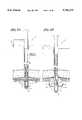
- FIG. 9A and FIG. 9Bare detailed cross sectional views of the distal end of the suture application system.
- a cannular body 718is comprised of the housing halves 720a,b. It is to be understood that for clarity only one of the housing halves 720 of the cannular body 718 is shown in FIG. 9A and FIG. 9B.
- the housing halves 720are configured to create a guided pathway 722 which is comprised of a needle carrier guide track 724 and a flexible carrier driver guide track 726.
- a needle carrier 728 and flexible carrier driver 730are joined at an end 732 of the needle carrier 728.
- a bullet needle 734includes a shoulder 736, a point 738 and a shaft 740.
- a length of suture material 742is attached to the shaft 740 by placing it in a hole 744 and holding it there by suitable means, such as crimping or adhesive bonding or the like.
- catch pockets 746a,bare incorporated in the housing halves 720 which position and retain a needle catch 748. Referring to FIG. 10, which is a detail plan view taken along the lines of 10--10 of FIG. 9A, it may be seen that the needle catch 748 includes openings 750 defined by ribs 752.
- the configuration and function of the needle catch 748is similar to that described earlier in FIG. 2C.
- the bullet needle 734is inserted into an end 754 of the needle carrier 728.
- the shoulder 736 of the bullet needle 734rests on the end 754 of the needle carrier 728, said end 754 dimensioned to hold and retain the bullet needle 734 in a manner previously described.
- the catch 748is fabricated by means of chemical etching, the most preferred method is to etch from a single side, known in the art as single sided etching.
- the ribs 752have a tapered cross section 753 as shown in FIG. 11, which is a detail cross sectional view taken along the lines of 11--11 of FIG. 10.
- the tapered cross section 753helps to guide the needle 734 into the catch openings 750, minimizing the chance of the needle 734 hitting the top of the ribs 752.
- FIGS. 9A and 9Bthe operation of this embodiment will be described. It is to be understood that the function of this embodiment is similar to that previously described in FIGS. 1A through 1H, that is, to approximate and close the puncture wounds created when surgical trocars are introduced into a body cavity. For clarity, the imposition of tissue planes along the path of needle travel to be described in FIGS. 9A and 9B has not been shown, although it is implied.
- FIG. 9Ashows the bullet needle 734 loaded into the needle carrier 728 which is depicted in the retracted position. In this position, the cannular body 718 may be passed through a surgical trocar and into a body cavity for operation of the device. As shown in FIG.
- the flexible carrier driver 730As the flexible carrier driver 730 is advanced into the needle guide track 724, the needle carrier 728, holding the bullet needle 734 and trailing the suture 742 is driven on a semi-circular path terminating in the needle catch 748.
- the bullet needle 734is captured by the catch 748 in a manner previously described in FIG. 2C.
- the flexible carrier driver 730may be retracted back into the flexible carrier driver guide track 726, causing the needle carrier 728 to rotate back into the needle carrier guide track 724 in the body half 720.
- the instrumentmay be removed from the surgical trocar, and the process repeated on the other side of the wound, and after knots have been tied, an approximation of the puncture wound is accomplished. It may be seen that a knot pusher such as that described in FIG.
- the suture applicator 8may be incorporated into the distal end of this embodiment of the suture applicator to effect the tying of knots for approximation of the puncture wounds. As such, the knots would be pushed directly into the wound, and not necessarily through the surgical trocar.
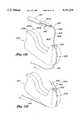
- FIG. 9C and FIG. 9Dare detailed cross sectional views of the distal end of the suture application system and are similar in construction to those already described in FIGS. 9A and 9B.
- a cannular body 770is comprised of the housing halves 772a,b. It is to be understood that for clarity only one of the housing halves 772 of the cannular body 770 is shown in FIG. 9C and FIG. 9D.
- the housing halves 772are configured to create a guided pathway 774 which is comprised of a needle carrier guide track 776 and a flexible carrier driver guide track 778.
- a needle carrier 780 and flexible carrier driver 782are joined at saddle 784 of the needle carrier 780.
- the saddle 784comprises a channel, groove or opening formed in the proximate end of the needle carrier 780 into which the flexible carrier driver 782 may enter circumferentially as opposed to axially.
- the attachment between the needle carrier 780 and the flexible carrier driver 782 at the saddle 784can be accomplished by crimping, welding, adhesive bonding or various other techniques.
- a bullet needle 786includes a shoulder 788, a point 790 and a shaft 792.
- a length of suture material 794is attached to the shaft 792 by placing it in a hole 796 and holding it there by suitable means, such as crimping or adhesive bonding or the like.
- catch pockets 798a,bwhich position and retain a needle catch 800.
- the configuration and function of the needle catch 800is similar to that described earlier in FIG. 2C.
- the bullet needle 786is inserted into an end 802 of the needle carrier 780.
- the shoulder 788 of the bullet needle 786rests on the end 802 of the needle carrier 780, said end 802 dimensioned to hold and retain the bullet needle 786 in a manner previously described.
- the operation of this embodimentis virtually identical to that described in FIGS. 9A and 9B, there are improvements included in this embodiment to the overall operation of the suture system.
- the circumferential length of the needle carrier 728 left inside the needle carrier guide track 724is quite minimal. This can allow the needle carrier 728 holding the needle 734 to drift off of the predescribed arcuate path which terminates in the needle catch 748. This drift may allow the needle 734 to miss the catch 748, causing an incomplete suturing cycle. It is desirable, then, to increase the circumferential length of the needle carrier left inside the guide track in order to improve the guidance of the needle carrier.
- FIGS. 9C and 9Dshows the needle carrier 780 with the saddle 784.
- the saddle 784allows the flexible carrier driver 782 to exit from the needle carrier 780 at a point along the circumference, rather than at a distal end 804. This may be seen to increase the overall arc length of the needle carrier 780 when compared with the needle carrier 728 shown in FIG. 9A.
- the flexible carrier driver 782is slidably moved in the guided pathway 774, and the needle carrier 780 is caused to rotate within the needle carrier guide track 776, it may be seen by referring to FIG. 9D that when the bullet needle 786 enters the needle catch 800, a significantly larger portion of the needle carrier 780 is still captured within the needle carrier guide track 776. This may be seen to provide additional guidance to the needle carrier 780 as it penetrates tissue. It may also be seen that the geometry described above allows for a longer stroke length, and therefor greater tissue bite.
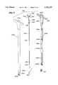
- FIG. 12is detailed cross sectional view of the distal end of a suture application system and is similar in construction to that previously described in FIG. 3.
- a cannular body 810which includes housing halves 812a,b and articulating tips 814a,b. It is to be understood that for clarity only one of the housing halves 812 and articulating tips 814 of the cannular body 810 is shown in FIG. 12.
- the housing half 812is joined to the articulating tip 814 at a pivot 816, and are configured to comprise a continuous pathway 818.
- a rigid tube 820is attached to a flexible needle driver 822 in a manner previously described, and is slidably disposed within the continuous pathway 818.
- a needle 824is slidably and rotationally disposed within a needle groove 826.
- the pivot 816includes an angular opening 828, said angular opening 828 and the needle groove 826 being part of the continuous pathway 818.
- the articulating tip 814may be rotated from the initial position shown, about the pivot 816 to the secondary position, with the flexible needle driver 822 being allowed to flex in the angular opening 828, preserving the continuous pathway 818.
- the operation of the needle driver portion of this embodimentis substantially the same as that described previously in FIGS. 3 and 5A-5D.
- the rotation of the articulating tip 814allows the needle 824 exit angle to be adjusted, as well as to allow the needle 824 to be positioned for access to tissues not directly approachable by a traditional needle driver.
- the requirements for the number of times the needle must be passed through tissuedepends on the operative procedure being performed by the surgeon. There are times when a running stitch, or uninterrupted suture must be placed, such as for the approximation of tissue flaps during the performance of a Nissen Fundoplication procedure for treatment of gastro-esophageal reflux disorder, or the repair of the uterus after a myomectomy. During these procedures, it may be convenient for the physician to reload the needle intracorporeally, that is, inside the body, in order to pass the needle through the tissue multiple times. Accordingly, we now describe an embodiment of a suture application system which allows the surgeon to reload the needle while the device is inside the body.
- the suture application systemincludes a cannular body 832 which is comprised of housing halves 834a,b and includes an opening 836 and a suture slot 838 formed in the housing halves 834a,b.
- a surgical needle 840includes a point 842, a needle body 844, and a distal end 846, in which is drilled a hole 848.
- a suture 850is crimped, adhesively bonded or otherwise attached to the needle 840 by inserting the suture into the hole 848.
- a grasper 852includes jaws 854a,b. It will be understood by those skilled in the art that grasper 852 is a common endoscopic tool used for tissue manipulation or other tasks requiring oppositional pinching. It may also be understood that endoscopic needle holders or the like may be substituted for the graspers illustrated here.
- FIG. 13Awhere the surgical needle 840 is shown being held in the jaws 854 of the grasper 852.
- the suture 850is trailing back from the needle 840 to tissue through which it has already been passed.
- the grasper 852 holding the needle 840is manipulated to hold the suture 850 in tension while the suture 850 is guided into the suture slot 838.
- the grasper 852is opened, releasing the needle 840, and by pulling on the suture 850 in the direction of the arrow as shown in FIG. 13A, the distal end 846 of the needle 840 is pulled into the opening 836 as shown in FIG. 13B.
- the needle 840may be completely pulled into the cannular body 832 by continued tension on the suture 850, and prepared for subsequent driving through tissue as previously described in the embodiments above.
Landscapes
- Health & Medical Sciences (AREA)
- Life Sciences & Earth Sciences (AREA)
- Surgery (AREA)
- Heart & Thoracic Surgery (AREA)
- Engineering & Computer Science (AREA)
- Biomedical Technology (AREA)
- Nuclear Medicine, Radiotherapy & Molecular Imaging (AREA)
- Medical Informatics (AREA)
- Molecular Biology (AREA)
- Animal Behavior & Ethology (AREA)
- General Health & Medical Sciences (AREA)
- Public Health (AREA)
- Veterinary Medicine (AREA)
- Surgical Instruments (AREA)
Abstract
Description
Claims (10)
Priority Applications (1)
| Application Number | Priority Date | Filing Date | Title |
|---|---|---|---|
| US08/743,886US5741279A (en) | 1992-09-04 | 1996-11-06 | Endoscopic suture system |
Applications Claiming Priority (5)
| Application Number | Priority Date | Filing Date | Title |
|---|---|---|---|
| US07/941,382US5364408A (en) | 1992-09-04 | 1992-09-04 | Endoscopic suture system |
| US08/057,699US5458609A (en) | 1992-09-04 | 1993-05-04 | Surgical needle and retainer system |
| US08/205,042US5540704A (en) | 1992-09-04 | 1994-03-02 | Endoscopic suture system |
| US08/311,967US5578044A (en) | 1992-09-04 | 1994-09-26 | Endoscopic suture system |
| US08/743,886US5741279A (en) | 1992-09-04 | 1996-11-06 | Endoscopic suture system |
Related Parent Applications (1)
| Application Number | Title | Priority Date | Filing Date |
|---|---|---|---|
| US08/311,967DivisionUS5578044A (en) | 1992-09-04 | 1994-09-26 | Endoscopic suture system |
Publications (1)
| Publication Number | Publication Date |
|---|---|
| US5741279Atrue US5741279A (en) | 1998-04-21 |
Family
ID=23209265
Family Applications (2)
| Application Number | Title | Priority Date | Filing Date |
|---|---|---|---|
| US08/311,967Expired - LifetimeUS5578044A (en) | 1992-09-04 | 1994-09-26 | Endoscopic suture system |
| US08/743,886Expired - LifetimeUS5741279A (en) | 1992-09-04 | 1996-11-06 | Endoscopic suture system |
Family Applications Before (1)
| Application Number | Title | Priority Date | Filing Date |
|---|---|---|---|
| US08/311,967Expired - LifetimeUS5578044A (en) | 1992-09-04 | 1994-09-26 | Endoscopic suture system |
Country Status (3)
| Country | Link |
|---|---|
| US (2) | US5578044A (en) |
| AU (1) | AU3512995A (en) |
| WO (1) | WO1996009796A2 (en) |
Cited By (91)
| Publication number | Priority date | Publication date | Assignee | Title |
|---|---|---|---|---|
| US6048351A (en)* | 1992-09-04 | 2000-04-11 | Scimed Life Systems, Inc. | Transvaginal suturing system |
| USD426635S (en)* | 1998-08-18 | 2000-06-13 | Genicon, Lc | Combination trocar, cannula, and valve |
| US6228096B1 (en)* | 1999-03-31 | 2001-05-08 | Sam R. Marchand | Instrument and method for manipulating an operating member coupled to suture material while maintaining tension on the suture material |
| USD443360S1 (en) | 2000-03-22 | 2001-06-05 | Dexterity Surgical Inc. | Distal end of obturator for a trocar |
| USD449887S1 (en) | 2000-01-26 | 2001-10-30 | Genicon Lc | Combined obturator, cannula and valve assembly |
| US6332888B1 (en) | 1998-02-12 | 2001-12-25 | Urogyn Ltd. | Finger-guided surgical instrument |
| US6475135B1 (en) | 2000-05-25 | 2002-11-05 | Urogyn Ltd. | Finger-guided suture device |
| EP1254635A1 (en)* | 2001-05-04 | 2002-11-06 | Francis Navarro | Subcutaneous suturing device for closing abdominal wall port of a patient |
| US20020165566A1 (en)* | 1995-10-09 | 2002-11-07 | Ulf Ulmsten | Surgical instrument and method for treating female urinary incontinence |
| US20020173800A1 (en)* | 2001-05-21 | 2002-11-21 | Peter Dreyfuss | Suture passer |
| WO2002096296A1 (en) | 2001-05-30 | 2002-12-05 | Ams Research Corporation | Surgical suture passer |
| US20020193810A1 (en)* | 2001-06-15 | 2002-12-19 | John Donald Hill | Suture placement apparatus |
| US20030055313A1 (en)* | 2001-08-31 | 2003-03-20 | Anderson Kimberly A. | Surgical articles for placing an implant about a tubular tissue structure and methods |
| US20030153946A1 (en)* | 2000-08-11 | 2003-08-14 | Edwards Lifesciences Ag | Device and method for treatment of atrioventricular regurgitation |
| WO2003073943A1 (en) | 2002-03-01 | 2003-09-12 | Intellimed Surgical Solutions Llc. | Puncture site closure device |
| US6626930B1 (en) | 1999-10-21 | 2003-09-30 | Edwards Lifesciences Corporation | Minimally invasive mitral valve repair method and apparatus |
| US20030187467A1 (en)* | 2002-03-26 | 2003-10-02 | Stefan Schreck | Sequential heart valve leaflet repair device and method of use |
| US20030233107A1 (en)* | 2002-06-12 | 2003-12-18 | Scimed Life Systems, Inc. | Suturing instrument with multi-load cartridge |
| US20040044365A1 (en)* | 2002-09-03 | 2004-03-04 | Bachman Alan B. | Single catheter mitral valve repair device and method for use |
| US20040059350A1 (en)* | 1992-09-04 | 2004-03-25 | Scimed Life Systems, Inc. | Suturing instruments and methods of use |
| US6719764B1 (en) | 2001-08-24 | 2004-04-13 | Scimed Life Systems, Inc. | Forward deploying suturing device and methods of use |
| US20040104101A1 (en)* | 2002-11-27 | 2004-06-03 | Siemens Aktiengesellschaft | Transport system for articles, in particular containers for baggage pieces, and control method for the transport system |
| US6752810B1 (en)* | 2002-05-31 | 2004-06-22 | Pilling Weck Incorporated | Instrument and method for pulling and twisting a tie onto two separated items |
| US20040181238A1 (en)* | 2003-03-14 | 2004-09-16 | David Zarbatany | Mitral valve repair system and method for use |
| US20040236356A1 (en)* | 2003-05-21 | 2004-11-25 | Rioux Robert F. | Remotely-reloadable suturing device |
| US20040267286A1 (en)* | 2002-10-24 | 2004-12-30 | Hua Gao | Instrument for applying a tie to two items and method of making same |
| US7048748B1 (en) | 2001-03-21 | 2006-05-23 | Uestuener Emin Tuncay | Automatic surgical suturing instrument and method |
| US20060195121A1 (en)* | 2002-08-02 | 2006-08-31 | Boston Scientific Scimed, Inc. | Placing sutures |
| US7153319B1 (en) | 2000-01-26 | 2006-12-26 | Genico, Inc. | Trocar system having shielded trocar |
| US20060293699A1 (en)* | 2005-06-28 | 2006-12-28 | Boston Scientific Scimed, Inc | Low profile suturing instrument |
| US20070021312A1 (en)* | 2005-07-20 | 2007-01-25 | Chevron Oronite Company Llc | Crankcase lubricating oil composition for protection of silver bearings in locomotive diesel engines |
| US20070106329A1 (en)* | 2005-11-10 | 2007-05-10 | Reza Dabir | Sickle needle and method |
| US20070270890A1 (en)* | 2006-03-16 | 2007-11-22 | Dennis Miller | System and Method for Treating Tissue Wall Prolapse |
| US20080065156A1 (en)* | 2006-09-08 | 2008-03-13 | Hauser David L | Expandable clip for tissue repair |
| US20080091220A1 (en)* | 2006-10-13 | 2008-04-17 | Chu Michael S H | Placing multiple sutures |
| WO2008101078A3 (en)* | 2007-02-14 | 2008-11-13 | Bfkw Llc | Medical device fixation tool and method of fixation of a medical device |
| US20080281356A1 (en)* | 2007-05-08 | 2008-11-13 | Mark Chau | Suture-fastening clip |
| US20090062852A1 (en)* | 2007-08-29 | 2009-03-05 | Marino James F | Annular repair device and methods |
| US20090312772A1 (en)* | 2008-06-11 | 2009-12-17 | Boston Scientific Scimed, Inc. | Suturing instrument and method for uterine preservation |
| US20100069930A1 (en)* | 2008-09-16 | 2010-03-18 | VentralFix, Inc. | Method and apparatus for minimally invasive delivery, tensioned deployment and fixation of secondary material prosthetic devices in patient body tissue, including hernia repair within the patient's herniation site |
| US20100198237A1 (en)* | 2007-02-14 | 2010-08-05 | Sentinel Group, Llc | Mucosal capture fixation of medical device |
| US7878970B2 (en) | 2005-09-28 | 2011-02-01 | Boston Scientific Scimed, Inc. | Apparatus and method for suspending a uterus |
| US20110196389A1 (en)* | 2010-02-09 | 2011-08-11 | Coloplast A/S | Digital suture fixation system |
| US20110196386A1 (en)* | 2010-02-08 | 2011-08-11 | Coloplast A/S | Digital suture fixation system |
| US8123762B2 (en) | 2004-08-19 | 2012-02-28 | Boston Scientific Scimed, Inc. | Suturing instrument |
| US8372087B2 (en) | 2007-02-14 | 2013-02-12 | Bfkw, Llc | Medical device fixation tool and method of fixation of a medical device |
| US8529431B2 (en) | 2007-02-14 | 2013-09-10 | Bfkw, Llc | Bariatric device and method |
| WO2013134313A1 (en) | 2012-03-06 | 2013-09-12 | Phillip A. Williams, Md, Pc | Medical device, method and system thereof |
| US8568428B2 (en) | 2011-01-05 | 2013-10-29 | Coloplast A/S | Suture system and assembly including a tubular leader having a clasp |
| US8591528B2 (en) | 2011-02-24 | 2013-11-26 | Coloplast A/S | Suture system and assembly including a suture cap formed around a tubular sleeve |
| US8672831B2 (en) | 2004-10-15 | 2014-03-18 | Bfkw, Llc | Bariatric device and method |
| US8709021B2 (en) | 2006-11-07 | 2014-04-29 | Boston Scientific Scimed, Inc. | Suturing instrument |
| US8801727B2 (en) | 2011-07-08 | 2014-08-12 | Smith & Nephew, Inc. | Orthopedic suture passer and method |
| US8882834B2 (en) | 2011-07-08 | 2014-11-11 | Smith & Nephew, Inc. | Soft tissue repair |
| US8888849B2 (en) | 2011-07-08 | 2014-11-18 | Smith & Nephew, Inc. | Soft tissue repair |
| US8951263B2 (en) | 2011-07-08 | 2015-02-10 | Smith & Nephew, Inc. | Orthopedic suture passer and method |
| US9039721B2 (en) | 2011-11-07 | 2015-05-26 | C.R. Bard, Inc. | Instruments for delivering transfascial sutures and methods of transfascial suturing |
| US20150238181A1 (en)* | 2012-09-28 | 2015-08-27 | Tensor Surgical, Inc. | Transosseous attachment method and instruments |
| US9144483B2 (en) | 2006-01-13 | 2015-09-29 | Boston Scientific Scimed, Inc. | Placing fixation devices |
| US9161751B2 (en) | 2010-12-02 | 2015-10-20 | Coloplast A/S | Suture system and assembly |
| US9168120B2 (en) | 2011-09-09 | 2015-10-27 | Boston Scientific Scimed, Inc. | Medical device and methods of delivering the medical device |
| US9220495B2 (en) | 2011-02-10 | 2015-12-29 | Coloplast A/S | Suture system and assembly including a suture clip |
| US9357997B2 (en) | 2011-07-08 | 2016-06-07 | Smith & Nephew, Inc. | Suture passer and method |
| US9375338B2 (en) | 2011-05-20 | 2016-06-28 | Bfkw, Llc | Intraluminal device and method with enhanced anti-migration |
| US20160183934A1 (en)* | 2014-07-16 | 2016-06-30 | Tensor Surgical, Inc. | Passive retrieving interosseous suture passing device |
| US9387061B2 (en) | 2010-09-02 | 2016-07-12 | Boston Scientific Scimed, Inc. | Pelvic implants and methods of implanting the same |
| US9393007B2 (en) | 2010-06-09 | 2016-07-19 | C.R. Bard, Inc. | Instruments for delivering transfascial sutures, transfascial assemblies, and methods of transfascial suturing |
| WO2016196579A1 (en)* | 2015-06-01 | 2016-12-08 | Lsi Solutioins, Inc. | Needle for a minimally invasive surgical suturing device |
| WO2016196574A1 (en)* | 2015-06-01 | 2016-12-08 | Lsi Solutions, Inc. | Suturing device for minimally invasive surgery and needles and methods thereof |
| US9526648B2 (en) | 2010-06-13 | 2016-12-27 | Synerz Medical, Inc. | Intragastric device for treating obesity |
| US9545326B2 (en) | 2012-03-06 | 2017-01-17 | Bfkw, Llc | Intraluminal device delivery technique |
| US9554781B2 (en) | 2014-01-23 | 2017-01-31 | Lsi Solutions, Inc. | Minimally invasive surgical suturing device and method |
| US9662105B2 (en) | 2011-07-08 | 2017-05-30 | Smith & Nephew, Inc. | Suture passer and method |
| WO2017136027A1 (en)* | 2016-02-05 | 2017-08-10 | Dura Tap Llc | Devices and methods for suture placement |
| US9814555B2 (en) | 2013-03-12 | 2017-11-14 | Boston Scientific Scimed, Inc. | Medical device for pelvic floor repair and method of delivering the medical device |
| US9993243B2 (en) | 2014-09-09 | 2018-06-12 | Edwards Lifesciences Corporation | Finger-mounted surgical instruments and methods of use |
| US10188381B2 (en) | 2015-11-20 | 2019-01-29 | Dura Tap Llc | Suture repair device |
| US10271940B2 (en) | 2014-12-29 | 2019-04-30 | Bfkw, Llc | Fixation of intraluminal device |
| US10413436B2 (en) | 2010-06-13 | 2019-09-17 | W. L. Gore & Associates, Inc. | Intragastric device for treating obesity |
| US10420665B2 (en) | 2010-06-13 | 2019-09-24 | W. L. Gore & Associates, Inc. | Intragastric device for treating obesity |
| US10603031B2 (en) | 2017-02-03 | 2020-03-31 | Lsi Solutions, Inc. | Suturing device for minimally invasive surgery |
| US10779980B2 (en) | 2016-04-27 | 2020-09-22 | Synerz Medical, Inc. | Intragastric device for treating obesity |
| US11013629B2 (en) | 2014-12-29 | 2021-05-25 | Bfkw, Llc | Fixation of intraluminal device |
| US11020213B2 (en) | 2014-12-29 | 2021-06-01 | Bfkw, Llc | Fixation of intraluminal device |
| US11135078B2 (en) | 2010-06-13 | 2021-10-05 | Synerz Medical, Inc. | Intragastric device for treating obesity |
| US20220000473A1 (en)* | 2018-12-03 | 2022-01-06 | Mayo Foundation For Medical Education And Research | Method and device for vesicourethral anastomosis |
| US11246583B2 (en) | 2014-06-18 | 2022-02-15 | Boston Scientific Scimed, Inc. | Insertion devices, anchors, and methods for securing an implant |
| US11337688B2 (en) | 2015-06-01 | 2022-05-24 | Lsi Solutions, Inc. | Suturing device for minimally invasive surgery and needles and methods thereof |
| US11918204B2 (en) | 2015-06-01 | 2024-03-05 | Lsi Solutions, Inc. | Suturing device for minimally invasive surgery and needles and methods thereof |
| US12127958B2 (en) | 2019-03-25 | 2024-10-29 | Bfkw, Llc | Intraluminal device and method with anti-migration |
| US12138188B2 (en) | 2019-03-11 | 2024-11-12 | Bfkw, Llc | Single member intraluminal device and method of fixation |
Families Citing this family (178)
| Publication number | Priority date | Publication date | Assignee | Title |
|---|---|---|---|---|
| GB9405790D0 (en)* | 1994-03-23 | 1994-05-11 | Univ London | Sewing device |
| US5730747A (en)* | 1995-06-07 | 1998-03-24 | Smith & Nephew, Inc. | Suture passing forceps |
| US5935149A (en)* | 1995-06-07 | 1999-08-10 | Smith & Nephew Inc. | Suturing tissue |
| JP3729861B2 (en)* | 1995-06-07 | 2005-12-21 | メッドトロニック・インコーポレイテッド | Wound closure device |
| US5855585A (en)* | 1996-06-11 | 1999-01-05 | X-Site, L.L.C. | Device and method for suturing blood vessels and the like |
| US6436109B1 (en) | 1996-06-11 | 2002-08-20 | X-Site, L.L.C. | Device and method for suturing blood vessels and the like |
| US5728133A (en)* | 1996-07-09 | 1998-03-17 | Cardiologics, L.L.C. | Anchoring device and method for sealing percutaneous punctures in vessels |
| US5910105A (en)* | 1997-04-14 | 1999-06-08 | C.R. Bard, Inc. | Control handle for an endoscope |
| US5908426A (en)* | 1997-04-24 | 1999-06-01 | Pierce; Javin | Suture needle manipulator |
| US5817110A (en)* | 1997-05-06 | 1998-10-06 | Kronner; Richard F. | Abdominal incision suturing apparatus |
| WO1998056872A1 (en) | 1997-06-10 | 1998-12-17 | Exxon Chemical Patents Inc. | Pyrolysis furnace with an internally finned u-shaped radiant coil |
| IL121752A0 (en) | 1997-09-11 | 1998-02-22 | Gaber Benny | Stitching tool |
| US6139556A (en)* | 1997-10-29 | 2000-10-31 | X-Site, L.L.C. | Device and method for suturing blood vessels and the like |
| US6042601A (en)* | 1998-03-18 | 2000-03-28 | United States Surgical Corporation | Apparatus for vascular hole closure |
| WO1999047050A2 (en)* | 1998-03-20 | 1999-09-23 | Scimed Life Systems, Inc. | Endoscopic suture systems |
| US5980539A (en)* | 1998-05-06 | 1999-11-09 | X-Site L.L.C. | Device and method for suturing blood vessels and the like |
| US6200329B1 (en) | 1998-08-31 | 2001-03-13 | Smith & Nephew, Inc. | Suture collet |
| US7842048B2 (en) | 2006-08-18 | 2010-11-30 | Abbott Laboratories | Articulating suture device and method |
| AU4055700A (en) | 1999-04-01 | 2000-10-23 | David B. Bjerken | Vacuum-assisted remote suture placement system |
| US6051006A (en)* | 1999-04-12 | 2000-04-18 | Smith & Nephew, Inc. | Suture-passing forceps |
| US6689153B1 (en) | 1999-04-16 | 2004-02-10 | Orthopaedic Biosystems Ltd, Inc. | Methods and apparatus for a coated anchoring device and/or suture |
| EP1261282B1 (en) | 2000-03-03 | 2013-09-25 | C. R. Bard, Inc. | Endoscopic tissue apposition device with multiple suction ports |
| US7993368B2 (en) | 2003-03-13 | 2011-08-09 | C.R. Bard, Inc. | Suture clips, delivery devices and methods |
| US6451031B1 (en) | 2000-03-21 | 2002-09-17 | X-Site, L.L.C. | Blood vessel suturing device with single guide-wire/needle receiving lumen |
| US7131979B2 (en) | 2002-05-17 | 2006-11-07 | Dvl Acquisition Sub, Inc. | Surgical suturing instrument and method of use |
| ES2435094T3 (en) | 2000-05-19 | 2013-12-18 | C.R. Bard, Inc. | Device and method of tissue capture and suturing |
| AU2002246923A1 (en) | 2000-10-20 | 2002-07-30 | Onux Medical, Inc. | Surgical suturing instrument and method of use |
| US7033373B2 (en) | 2000-11-03 | 2006-04-25 | Satiety, Inc. | Method and device for use in minimally invasive placement of space-occupying intragastric devices |
| US7131980B1 (en) | 2001-01-18 | 2006-11-07 | Dvl Acquisitions Sub, Inc. | Surgical suturing instrument and method of use |
| US7083629B2 (en) | 2001-05-30 | 2006-08-01 | Satiety, Inc. | Overtube apparatus for insertion into a body |
| US6558400B2 (en) | 2001-05-30 | 2003-05-06 | Satiety, Inc. | Obesity treatment tools and methods |
| EP2308391B1 (en) | 2001-06-14 | 2016-08-31 | Endoevolution, Llc | Apparatus for surgical suturing with thread management |
| US7011668B2 (en) | 2001-07-23 | 2006-03-14 | Dvl Acquistion Sub, Inc. | Surgical suturing instrument and method of use |
| US7112208B2 (en)* | 2001-08-06 | 2006-09-26 | Morris John K | Compact suture punch with malleable needle |
| US20040249394A1 (en)* | 2001-08-06 | 2004-12-09 | Arthrex, Inc. | Compact suture punch with malleable needle |
| JP2005502416A (en) | 2001-09-14 | 2005-01-27 | オーナックス・メディカル・インコーポレーテッド | Surgical suture instrument and method of use |
| US6712849B2 (en)* | 2001-10-01 | 2004-03-30 | Scandius Biomedical, Inc. | Apparatus and method for reconstructing a ligament |
| US7520898B2 (en)* | 2001-10-01 | 2009-04-21 | Scandius Biomedical, Inc. | Apparatus and method for reconstructing a ligament |
| US7402166B2 (en)* | 2002-02-15 | 2008-07-22 | A&P Feigl Family Limited Partnership | Devices and methods for positioning sutures |
| CA2477220C (en) | 2002-03-14 | 2007-11-06 | Jeffrey E. Yeung | Suture anchor and approximating device |
| AU2003223672A1 (en)* | 2002-04-17 | 2003-11-03 | Tyco Healthcare Group Lp | Method and apparatus for anastomosis including an expandable anchor |
| US7122039B2 (en)* | 2002-05-01 | 2006-10-17 | Boston Scientific Scimed, Inc. | Tying knots |
| JP2005525862A (en) | 2002-05-17 | 2005-09-02 | オーナックス・メディカル・インコーポレーテッド | Surgical suture instrument and method of use thereof |
| US6984237B2 (en) | 2002-05-22 | 2006-01-10 | Orthopaedic Biosystems Ltd., Inc. | Suture passing surgical instrument |
| US8083804B2 (en) | 2002-06-19 | 2011-12-27 | Tyco Healthcare Group Lp | Method and apparatus for anastomosis including annular joining member |
| ES2356069T3 (en)* | 2002-06-19 | 2011-04-04 | Tyco Healthcare Group Lp | APPARATUS FOR ANASTOMOSIS AFTER A RADICAL PROSTATECTOMY. |
| JP4384033B2 (en)* | 2002-06-19 | 2009-12-16 | タイコ ヘルスケア グループ エルピー | Method and apparatus for anastomosis |
| AU2003237077A1 (en)* | 2002-06-20 | 2004-01-06 | Tyco Healthcare Group, Lp | Method and apparatus for anastomosis including an anchoring sleeve |
| US7510560B2 (en)* | 2002-06-20 | 2009-03-31 | Tyco Healthcare Group Lp | Method and apparatus for anastomosis including an anchoring sleeve |
| US7998155B2 (en)* | 2002-06-20 | 2011-08-16 | Tyco Healthcare Group Lp | Method and apparatus for anastomosis including annular joining member |
| US6936054B2 (en)* | 2002-07-22 | 2005-08-30 | Boston Scientific Scimed, Inc. | Placing sutures |
| JP4580756B2 (en) | 2002-07-23 | 2010-11-17 | コヴィディエン・アクチェンゲゼルシャフト | IVS obturator instrument and procedure |
| US6746460B2 (en) | 2002-08-07 | 2004-06-08 | Satiety, Inc. | Intra-gastric fastening devices |
| US7214233B2 (en) | 2002-08-30 | 2007-05-08 | Satiety, Inc. | Methods and devices for maintaining a space occupying device in a relatively fixed location within a stomach |
| US7033384B2 (en) | 2002-08-30 | 2006-04-25 | Satiety, Inc. | Stented anchoring of gastric space-occupying devices |
| US7229428B2 (en) | 2002-10-23 | 2007-06-12 | Satiety, Inc. | Method and device for use in endoscopic organ procedures |
| US7220237B2 (en) | 2002-10-23 | 2007-05-22 | Satiety, Inc. | Method and device for use in endoscopic organ procedures |
| US6656194B1 (en) | 2002-11-05 | 2003-12-02 | Satiety, Inc. | Magnetic anchoring devices |
| US6896685B1 (en) | 2003-01-29 | 2005-05-24 | James A. Davenport | Suture device |
| US7175638B2 (en) | 2003-04-16 | 2007-02-13 | Satiety, Inc. | Method and devices for modifying the function of a body organ |
| CN1822794B (en) | 2003-05-16 | 2010-05-26 | C.R.巴德有限公司 | Single cannula, multiple needle endoscopic suturing system |
| US7794471B1 (en)* | 2003-06-26 | 2010-09-14 | Cardica, Inc. | Compliant anastomosis system |
| US8574246B1 (en) | 2004-06-25 | 2013-11-05 | Cardica, Inc. | Compliant anastomosis system utilizing suture |
| US7462188B2 (en) | 2003-09-26 | 2008-12-09 | Abbott Laboratories | Device and method for suturing intracardiac defects |
| US7914543B2 (en) | 2003-10-14 | 2011-03-29 | Satiety, Inc. | Single fold device for tissue fixation |
| US7097650B2 (en) | 2003-10-14 | 2006-08-29 | Satiety, Inc. | System for tissue approximation and fixation |
| EP1686902A1 (en)* | 2003-11-27 | 2006-08-09 | George Kaladelfos | Ligature carrier |
| US7449024B2 (en) | 2003-12-23 | 2008-11-11 | Abbott Laboratories | Suturing device with split arm and method of suturing tissue |
| US20050177176A1 (en) | 2004-02-05 | 2005-08-11 | Craig Gerbi | Single-fold system for tissue approximation and fixation |
| CA2556228C (en) | 2004-02-13 | 2014-05-13 | Satiety, Inc. | Methods for reducing hollow organ volume |
| MXPA06009971A (en) | 2004-02-27 | 2007-08-08 | Satiety Inc | Methods and devices for reducing hollow organ volume. |
| US8449560B2 (en) | 2004-03-09 | 2013-05-28 | Satiety, Inc. | Devices and methods for placement of partitions within a hollow body organ |
| US8628547B2 (en) | 2004-03-09 | 2014-01-14 | Ethicon Endo-Surgery, Inc. | Devices and methods for placement of partitions within a hollow body organ |
| US9028511B2 (en) | 2004-03-09 | 2015-05-12 | Ethicon Endo-Surgery, Inc. | Devices and methods for placement of partitions within a hollow body organ |
| US8252009B2 (en) | 2004-03-09 | 2012-08-28 | Ethicon Endo-Surgery, Inc. | Devices and methods for placement of partitions within a hollow body organ |
| AU2005231323B2 (en) | 2004-03-26 | 2011-03-31 | Ethicon Endo-Surgery, Inc | Systems and methods for treating obesity |
| ZA200610827B (en) | 2004-05-21 | 2008-07-30 | Neatstich Ltd | Suture device |
| EP1755461B1 (en) | 2004-06-16 | 2014-01-01 | Smith & Nephew, Inc. | Suture passing device |
| US8123764B2 (en) | 2004-09-20 | 2012-02-28 | Endoevolution, Llc | Apparatus and method for minimally invasive suturing |
| US7976555B2 (en) | 2008-07-17 | 2011-07-12 | Endoevolution, Llc | Apparatus and method for minimally invasive suturing |
| US9775600B2 (en) | 2010-10-01 | 2017-10-03 | Endoevolution, Llc | Devices and methods for minimally invasive suturing |
| US7993354B1 (en) | 2010-10-01 | 2011-08-09 | Endoevolution, Llc | Devices and methods for minimally invasive suturing |
| CN101027001B (en)* | 2004-09-27 | 2010-05-26 | 苏图诺有限公司 | Handle for suturing apparatus |
| US20060106288A1 (en) | 2004-11-17 | 2006-05-18 | Roth Alex T | Remote tissue retraction device |
| US8038687B2 (en)* | 2005-05-17 | 2011-10-18 | St. Jude Medical Puerto Rico Llc | Suture loop closure device |
| US9149266B2 (en) | 2005-05-20 | 2015-10-06 | Neotract, Inc. | Deforming anchor device |
| US8834492B2 (en) | 2005-05-20 | 2014-09-16 | Neotract, Inc. | Continuous indentation lateral lobe apparatus and method |
| US8628542B2 (en) | 2005-05-20 | 2014-01-14 | Neotract, Inc. | Median lobe destruction apparatus and method |
| US7645286B2 (en) | 2005-05-20 | 2010-01-12 | Neotract, Inc. | Devices, systems and methods for retracting, lifting, compressing, supporting or repositioning tissues or anatomical structures |
| US7758594B2 (en) | 2005-05-20 | 2010-07-20 | Neotract, Inc. | Devices, systems and methods for treating benign prostatic hyperplasia and other conditions |
| US9364212B2 (en) | 2005-05-20 | 2016-06-14 | Neotract, Inc. | Suture anchoring devices and methods for use |
| US9504461B2 (en) | 2005-05-20 | 2016-11-29 | Neotract, Inc. | Anchor delivery system |
| US10925587B2 (en) | 2005-05-20 | 2021-02-23 | Neotract, Inc. | Anchor delivery system |
| US8491606B2 (en) | 2005-05-20 | 2013-07-23 | Neotract, Inc. | Median lobe retraction apparatus and method |
| US9549739B2 (en) | 2005-05-20 | 2017-01-24 | Neotract, Inc. | Devices, systems and methods for treating benign prostatic hyperplasia and other conditions |
| US8603106B2 (en) | 2005-05-20 | 2013-12-10 | Neotract, Inc. | Integrated handle assembly for anchor delivery system |
| US10195014B2 (en) | 2005-05-20 | 2019-02-05 | Neotract, Inc. | Devices, systems and methods for treating benign prostatic hyperplasia and other conditions |
| US7909836B2 (en) | 2005-05-20 | 2011-03-22 | Neotract, Inc. | Multi-actuating trigger anchor delivery system |
| US8216254B2 (en)* | 2005-05-20 | 2012-07-10 | Neotract, Inc. | Anchor delivery system with replaceable cartridge |
| US8668705B2 (en) | 2005-05-20 | 2014-03-11 | Neotract, Inc. | Latching anchor device |
| US8333776B2 (en)* | 2005-05-20 | 2012-12-18 | Neotract, Inc. | Anchor delivery system |
| US8529584B2 (en) | 2005-05-20 | 2013-09-10 | Neotract, Inc. | Median lobe band implant apparatus and method |
| US8157815B2 (en) | 2005-05-20 | 2012-04-17 | Neotract, Inc. | Integrated handle assembly for anchor delivery system |
| US8425535B2 (en) | 2005-05-20 | 2013-04-23 | Neotract, Inc. | Multi-actuating trigger anchor delivery system |
| US7896891B2 (en) | 2005-05-20 | 2011-03-01 | Neotract, Inc. | Apparatus and method for manipulating or retracting tissue and anatomical structure |
| US8394113B2 (en) | 2005-05-20 | 2013-03-12 | Neotract, Inc. | Coiled anchor device |
| US8945152B2 (en) | 2005-05-20 | 2015-02-03 | Neotract, Inc. | Multi-actuating trigger anchor delivery system |
| EP1909655A2 (en) | 2005-06-20 | 2008-04-16 | Sutura, Inc. | Method and apparatus for applying a knot to a suture |
| CA2854625C (en) | 2006-01-27 | 2017-01-24 | Suturtek Incorporated | Apparatus and method for tissue closure |
| US9005220B2 (en) | 2006-04-04 | 2015-04-14 | C.R. Bard, Inc. | Suturing devices and methods with energy emitting elements |
| US8834494B2 (en)* | 2006-10-20 | 2014-09-16 | St. Jude Medical, Cardiology Division, Inc. | Method and device for automated needle deployment |
| ATE514382T1 (en) | 2006-11-30 | 2011-07-15 | Wilson Cook Medical Inc | FABRIC ANCHOR FOR SEAM CLOSURE OF PERFORATIONS |
| WO2008082992A1 (en)* | 2007-01-04 | 2008-07-10 | Boston Scientific Limited | Locating and occluding vessels |
| US8246636B2 (en) | 2007-03-29 | 2012-08-21 | Nobles Medical Technologies, Inc. | Suturing devices and methods for closing a patent foramen ovale |
| US8740937B2 (en) | 2007-05-31 | 2014-06-03 | Cook Medical Technologies Llc | Suture lock |
| US9861354B2 (en) | 2011-05-06 | 2018-01-09 | Ceterix Orthopaedics, Inc. | Meniscus repair |
| US9314234B2 (en) | 2007-07-03 | 2016-04-19 | Ceterix Orthopaedics, Inc. | Pre-tied surgical knots for use with suture passers |
| US8702731B2 (en) | 2007-07-03 | 2014-04-22 | Ceterix Orthopaedics, Inc. | Suturing and repairing tissue using in vivo suture loading |
| US8911456B2 (en) | 2007-07-03 | 2014-12-16 | Ceterix Orthopaedics, Inc. | Methods and devices for preventing tissue bridging while suturing |
| US8500809B2 (en) | 2011-01-10 | 2013-08-06 | Ceterix Orthopaedics, Inc. | Implant and method for repair of the anterior cruciate ligament |
| US8663253B2 (en) | 2007-07-03 | 2014-03-04 | Ceterix Orthopaedics, Inc. | Methods of meniscus repair |
| US8465505B2 (en) | 2011-05-06 | 2013-06-18 | Ceterix Orthopaedics, Inc. | Suture passer devices and methods |
| US9211119B2 (en) | 2007-07-03 | 2015-12-15 | Ceterix Orthopaedics, Inc. | Suture passers and methods of passing suture |
| US8821518B2 (en) | 2007-11-05 | 2014-09-02 | Ceterix Orthopaedics, Inc. | Suture passing instrument and method |
| US10441273B2 (en) | 2007-07-03 | 2019-10-15 | Ceterix Orthopaedics, Inc. | Pre-tied surgical knots for use with suture passers |
| US8758366B2 (en) | 2007-07-09 | 2014-06-24 | Neotract, Inc. | Multi-actuating trigger anchor delivery system |
| JP5297458B2 (en) | 2007-08-17 | 2013-09-25 | クック メディカル テクノロジーズ エルエルシー | Device for opening and closing a body wall |
| US8236013B2 (en)* | 2007-10-19 | 2012-08-07 | Boston Scientific Scimed, Inc. | Apparatus for placing medical implants |
| AU2009204417B2 (en) | 2008-01-03 | 2013-05-09 | Cook Medical Technologies Llc | Medical systems and devices for endoscopically suturing perforations |
| US8771296B2 (en) | 2008-05-09 | 2014-07-08 | Nobles Medical Technologies Inc. | Suturing devices and methods for suturing an anatomic valve |
| US9867610B2 (en)* | 2008-06-17 | 2018-01-16 | Apollo Endosurgery Us, Inc. | Endoscopic suturing system with retained end cap |
| US11812951B2 (en) | 2008-06-17 | 2023-11-14 | Apollo Endosurgery Us, Inc. | Endoscopic needle assembly |
| WO2010014825A1 (en)* | 2008-07-30 | 2010-02-04 | Neotract, Inc. | Slotted anchor device |
| EP2341841B1 (en) | 2008-09-29 | 2019-12-04 | C.R.Bard, Inc. | Endoscopic suturing device |
| CA2757554A1 (en) | 2009-04-03 | 2010-10-07 | Cook Medical Technologies Llc | Tissue anchors and medical devices for rapid deployment of tissue anchors |
| WO2010151382A1 (en) | 2009-06-26 | 2010-12-29 | Wilson-Cook Medical Inc. | Linear clamps for anastomosis |
| DK200970073A (en)* | 2009-07-22 | 2011-01-23 | Coloplast As | Suturing system and assembly |
| US8545525B2 (en) | 2009-11-03 | 2013-10-01 | Cook Medical Technologies Llc | Planar clamps for anastomosis |
| US9848868B2 (en) | 2011-01-10 | 2017-12-26 | Ceterix Orthopaedics, Inc. | Suture methods for forming locking loops stitches |
| US9011454B2 (en) | 2009-11-09 | 2015-04-21 | Ceterix Orthopaedics, Inc. | Suture passer with radiused upper jaw |
| US11744575B2 (en) | 2009-11-09 | 2023-09-05 | Ceterix Orthopaedics, Inc. | Suture passer devices and methods |
| JP5719374B2 (en) | 2009-11-09 | 2015-05-20 | セテリックス オーソピーディクス インコーポレイテッド | Device, system, and method for repairing a meniscus |
| US8603121B2 (en) | 2010-04-14 | 2013-12-10 | Cook Medical Technologies Llc | Systems and methods for creating anastomoses |
| US9370353B2 (en) | 2010-09-01 | 2016-06-21 | Abbott Cardiovascular Systems, Inc. | Suturing devices and methods |
| US9913638B2 (en) | 2011-01-10 | 2018-03-13 | Ceterix Orthopaedics, Inc. | Transosteal anchoring methods for tissue repair |
| US8556916B2 (en) | 2011-02-14 | 2013-10-15 | Smith & Nephew, Inc. | Method and device for suture manipulation |
| EP2683304B1 (en) | 2011-03-10 | 2019-09-25 | Boston Scientific Scimed, Inc. | Flexible suturing instrument |
| US9161749B2 (en) | 2011-04-14 | 2015-10-20 | Neotract, Inc. | Method and apparatus for treating sexual dysfunction |
| US8992550B2 (en) | 2011-07-20 | 2015-03-31 | Coloplast A/S | Suture system with capsule eyelet providing multiple suture tissue fixation |
| US9492162B2 (en) | 2013-12-16 | 2016-11-15 | Ceterix Orthopaedics, Inc. | Automatically reloading suture passer devices and methods |
| US10524778B2 (en) | 2011-09-28 | 2020-01-07 | Ceterix Orthopaedics | Suture passers adapted for use in constrained regions |
| US10292801B2 (en) | 2012-03-29 | 2019-05-21 | Neotract, Inc. | System for delivering anchors for treating incontinence |
| US8858573B2 (en) | 2012-04-10 | 2014-10-14 | Abbott Cardiovascular Systems, Inc. | Apparatus and method for suturing body lumens |
| WO2013165942A1 (en) | 2012-05-01 | 2013-11-07 | Brigham And Women's Hospital, Inc. | Suturing device for laparoscopic procedures |
| US9241707B2 (en) | 2012-05-31 | 2016-01-26 | Abbott Cardiovascular Systems, Inc. | Systems, methods, and devices for closing holes in body lumens |
| US10130353B2 (en) | 2012-06-29 | 2018-11-20 | Neotract, Inc. | Flexible system for delivering an anchor |
| WO2015002815A1 (en) | 2013-07-02 | 2015-01-08 | Med-Venture Investments, Llc | Suturing devices and methods for suturing an anatomic structure |
| US9247935B2 (en) | 2013-09-23 | 2016-02-02 | Ceterix Orthopaedics, Inc. | Arthroscopic knot pusher and suture cutter |
| JP6469109B2 (en) | 2013-12-06 | 2019-02-13 | メッド − ベンチャー インベストメンツ、エルエルシー | Suture method and apparatus |
| CN204951031U (en) | 2014-04-08 | 2016-01-13 | 赛特里克斯整形公司 | Ware device is worn to draw by suture |
| CN106456155A (en) | 2014-04-24 | 2017-02-22 | 史密夫和内修有限公司 | Suture passer |
| US10178993B2 (en) | 2014-07-11 | 2019-01-15 | Cardio Medical Solutions, Inc. | Device and method for assisting end-to-side anastomosis |
| US9936943B1 (en) | 2014-08-07 | 2018-04-10 | Nicholas MANCINI | Suture passing surgical device with atraumatic grasper preventing accidental perforations |
| US10226245B2 (en) | 2015-07-21 | 2019-03-12 | Ceterix Orthopaedics, Inc. | Automatically reloading suture passer devices that prevent entanglement |
| US10405853B2 (en) | 2015-10-02 | 2019-09-10 | Ceterix Orthpaedics, Inc. | Knot tying accessory |
| WO2018081374A1 (en) | 2016-10-31 | 2018-05-03 | Smith & Nephew, Inc. | Suture passer and grasper instrument and method |
| WO2018119459A1 (en) | 2016-12-23 | 2018-06-28 | Brigham And Women's Hospital, Inc. | Systems and methods for suturing tissue |
| US10426449B2 (en) | 2017-02-16 | 2019-10-01 | Abbott Cardiovascular Systems, Inc. | Articulating suturing device with improved actuation and alignment mechanisms |
| US20180242967A1 (en) | 2017-02-26 | 2018-08-30 | Endoevolution, Llc | Apparatus and method for minimally invasive suturing |
| US10463362B2 (en) | 2017-04-18 | 2019-11-05 | Durastat Llc | Devices and methods for suture placement |
| EP4115818A3 (en) | 2017-06-19 | 2023-04-05 | Heartstitch, Inc. | Suturing systems and methods for suturing body tissue |
| US10292698B2 (en) | 2017-07-27 | 2019-05-21 | Endoevolution, Llc | Apparatus and method for minimally invasive suturing |
| ES2953556T3 (en) | 2017-12-23 | 2023-11-14 | Teleflex Life Sciences Ltd | Expandable Tissue Docking Apparatus |
| CN111374737A (en)* | 2018-12-29 | 2020-07-07 | 江苏风和医疗器材股份有限公司 | Puncture core subassembly and puncture ware |
| US11963673B1 (en)* | 2019-08-23 | 2024-04-23 | New Wave Endo-Surgical Corp. | Laparoscopic port closure and nerve block kit |
| CN114286646B (en) | 2020-08-03 | 2024-03-08 | 泰利福生命科学有限公司 | Handle and cassette system for medical intervention |
| US12011161B2 (en)* | 2021-01-21 | 2024-06-18 | Ethicon, Inc. | Suture needle adaptors for delivering suture needles through cannulas while simultaneously visualizing the delivery of the suture needles through the cannulas |
| US12402877B2 (en) | 2021-06-07 | 2025-09-02 | Intuitive Surgical Operations, Inc. | Needle loader devices and related systems and methods |
Citations (61)
| Publication number | Priority date | Publication date | Assignee | Title |
|---|---|---|---|---|
| US342773A (en)* | 1886-06-01 | Needle | ||
| US919138A (en)* | 1909-03-16 | 1909-04-20 | Clarence A Drake | Surgical needle. |
| GB190818602A (en)* | 1908-09-04 | 1909-09-06 | Frank Mitchell | Improvements in and relating to Surgical Stitching Instruments. |
| US1037864A (en)* | 1911-04-20 | 1912-09-10 | John C Carlson | Surgical-needle holder. |
| US1449087A (en)* | 1921-12-05 | 1923-03-20 | Edwin P Bugbee | Suturing instrument |
| US1815725A (en)* | 1930-02-03 | 1931-07-21 | George P Pilling & Son Company | Suture forceps |
| US1822330A (en)* | 1930-01-13 | 1931-09-08 | Ainslie George | Suturing instrument |
| US2577240A (en)* | 1949-10-01 | 1951-12-04 | Robert L Findley | Suture hemostat |
| US2579192A (en)* | 1950-08-15 | 1951-12-18 | George H Sciaroni | Suturing instrument |
| US3013559A (en)* | 1959-05-06 | 1961-12-19 | Wesley C Thomas | Instrument for closing flesh wounds |
| CA647813A (en)* | 1962-09-04 | B. Kennison Adrian | Surgical needle | |
| US3160157A (en)* | 1962-03-29 | 1964-12-08 | Ethicon Inc | Surgical needle |
| US3470875A (en)* | 1966-10-06 | 1969-10-07 | Alfred A Johnson | Surgical clamping and suturing instrument |
| US3638653A (en)* | 1969-07-31 | 1972-02-01 | H Lee Berry | Suturing device |
| US3840017A (en)* | 1971-10-29 | 1974-10-08 | A Violante | Surgical instrument |
| US3918455A (en)* | 1974-04-29 | 1975-11-11 | Albany Int Corp | Combined surgical suture and needle |
| US3946740A (en)* | 1974-10-15 | 1976-03-30 | Bassett John W | Suturing device |
| US4161951A (en)* | 1978-04-27 | 1979-07-24 | Scanlan International, Inc. | Needle driver |
| US4164225A (en)* | 1977-12-28 | 1979-08-14 | Johnson & Lorenz, Inc. | Surgical suturing instrument |
| US4224947A (en)* | 1979-02-05 | 1980-09-30 | Mamoru Fukuda | Suturing apparatus |
| US4235177A (en)* | 1979-02-23 | 1980-11-25 | Raymond C. Kelder | Suturing device |
| US4236470A (en)* | 1979-01-17 | 1980-12-02 | Stenson Thomas K | Portable stitching device |
| US4312337A (en)* | 1980-09-08 | 1982-01-26 | Donohue Brian T | Cannula and drill guide apparatus |
| US4345601A (en)* | 1980-04-07 | 1982-08-24 | Mamoru Fukuda | Continuous suturing device |
| SU1028320A1 (en)* | 1981-08-03 | 1983-07-15 | Dekhtyar Anatolij L | Device for application of sutures by soft ligature |
| SU1093329A1 (en)* | 1983-04-07 | 1984-05-23 | Калининский Государственный Медицинский Институт | Suture appliance for soft tissue |
| US4493323A (en)* | 1982-12-13 | 1985-01-15 | University Of Iowa Research Foundation | Suturing device and method for using same |
| EP0140557A2 (en)* | 1983-09-12 | 1985-05-08 | Edward Lee Blackwood | Surgical instrument |
| US4548202A (en)* | 1983-06-20 | 1985-10-22 | Ethicon, Inc. | Mesh tissue fasteners |
| US4557265A (en)* | 1983-02-08 | 1985-12-10 | Innova Ab | Suturing instrument |
| US4596249A (en)* | 1983-07-26 | 1986-06-24 | Freda Vincent J | Implement for setting sutures |
| US4602635A (en)* | 1983-11-14 | 1986-07-29 | Mulhollan James S | Remote surgical knot tier and method of use |
| US4621640A (en)* | 1984-01-09 | 1986-11-11 | Mulhollan James S | Mechanical needle carrier and method for its use |
| US4635638A (en)* | 1984-02-07 | 1987-01-13 | Galil Advanced Technologies Ltd. | Power-driven gripping tool particularly useful as a suturing device |
| US4762260A (en)* | 1986-09-11 | 1988-08-09 | Ophthalmic Ventures Limited Partnership | Surgical microstapler |
| US4781190A (en)* | 1985-06-18 | 1988-11-01 | Lee Wilson K C | Method of arthroscopic repair of a limb joint |
| US4890615A (en)* | 1987-11-05 | 1990-01-02 | Concept, Inc. | Arthroscopic suturing instrument |
| US4898155A (en)* | 1984-09-26 | 1990-02-06 | Galil (Naharia) Advanced Technologies Ltd. | Suturing implement particularly useful in surgical operations for the attachment of a prosthetic valve |
| US4899746A (en)* | 1988-04-28 | 1990-02-13 | Brunk Industries, Inc. | Suturing apparatus |
| WO1990003766A1 (en)* | 1988-10-04 | 1990-04-19 | Peter Emanuel Petros | Surgical instrument prosthesis and method of utilisation of such |
| US4926860A (en)* | 1988-02-05 | 1990-05-22 | Flexmedics Corporation | ARthroscopic instrumentation and method |
| US4935027A (en)* | 1989-08-21 | 1990-06-19 | Inbae Yoon | Surgical suture instrument with remotely controllable suture material advancement |
| US4957498A (en)* | 1987-11-05 | 1990-09-18 | Concept, Inc. | Suturing instrument |
| US5037433A (en)* | 1990-05-17 | 1991-08-06 | Wilk Peter J | Endoscopic suturing device and related method and suture |
| US5047039A (en)* | 1990-09-14 | 1991-09-10 | Odis Lynn Avant | Method and apparatus for effecting dorsal vein ligation and tubular anastomosis and laparoscopic prostatectomy |
| US5067957A (en)* | 1983-10-14 | 1991-11-26 | Raychem Corporation | Method of inserting medical devices incorporating SIM alloy elements |
| GB2247841A (en)* | 1990-09-11 | 1992-03-18 | Javin Pierce | Pusher for surgical knot windings |
| US5100498A (en)* | 1988-06-17 | 1992-03-31 | Ngk Insulators, Ltd. | Method of producing a minutely patterned structure |
| US5100418A (en)* | 1987-05-14 | 1992-03-31 | Inbae Yoon | Suture tie device system and applicator therefor |
| US5100415A (en)* | 1990-01-08 | 1992-03-31 | Hayhurst John O | Knotting instrument |
| US5100421A (en)* | 1991-02-05 | 1992-03-31 | Cyprus Endosurgical Tools, Inc. | Christoudias curved needle suture assembly |
| WO1992012674A1 (en)* | 1991-01-17 | 1992-08-06 | Therkel Bisgaard | A set of tools for suturing in deep surgical apertures or body cavities |
| WO1993001750A1 (en)* | 1991-07-23 | 1993-02-04 | Kernforschungszentrum Karlsruhe Gmbh | Surgical stitching instrument |
| US5188636A (en)* | 1992-05-07 | 1993-02-23 | Ethicon, Inc. | Purse string suture instrument |
| US5258011A (en)* | 1987-01-12 | 1993-11-02 | Drews Robert C | Corneal rivet |
| EP0589409A1 (en)* | 1992-09-23 | 1994-03-30 | United States Surgical Corporation | Instrument for closing trocar puncture wounds |
| US5306281A (en)* | 1992-08-31 | 1994-04-26 | Merrimac Industries, Inc. | Suturing cassette device |
| US5308353A (en)* | 1992-08-31 | 1994-05-03 | Merrimac Industries, Inc. | Surgical suturing device |
| WO1994013211A1 (en)* | 1992-12-10 | 1994-06-23 | Perclose, Inc. | Vascular puncture site suturing device and method |
| US5391174A (en)* | 1991-11-29 | 1995-02-21 | Weston; Peter V. | Endoscopic needle holders |
| US5527321A (en)* | 1993-07-14 | 1996-06-18 | United States Surgical Corporation | Instrument for closing trocar puncture wounds |
Family Cites Families (3)
| Publication number | Priority date | Publication date | Assignee | Title |
|---|---|---|---|---|
| GB190918602A (en)* | 1909-08-12 | 1910-02-17 | Ross Hazelrigg | Improvements relating to Insect Traps. |
| US5364408A (en)* | 1992-09-04 | 1994-11-15 | Laurus Medical Corporation | Endoscopic suture system |
| US5540704A (en)* | 1992-09-04 | 1996-07-30 | Laurus Medical Corporation | Endoscopic suture system |
- 1994
- 1994-09-26USUS08/311,967patent/US5578044A/ennot_activeExpired - Lifetime
- 1995
- 1995-09-14WOPCT/US1995/011727patent/WO1996009796A2/enactiveApplication Filing
- 1995-09-14AUAU35129/95Apatent/AU3512995A/ennot_activeAbandoned
- 1996
- 1996-11-06USUS08/743,886patent/US5741279A/ennot_activeExpired - Lifetime
Patent Citations (68)
| Publication number | Priority date | Publication date | Assignee | Title |
|---|---|---|---|---|
| CA647813A (en)* | 1962-09-04 | B. Kennison Adrian | Surgical needle | |
| US342773A (en)* | 1886-06-01 | Needle | ||
| GB190818602A (en)* | 1908-09-04 | 1909-09-06 | Frank Mitchell | Improvements in and relating to Surgical Stitching Instruments. |
| US919138A (en)* | 1909-03-16 | 1909-04-20 | Clarence A Drake | Surgical needle. |
| US1037864A (en)* | 1911-04-20 | 1912-09-10 | John C Carlson | Surgical-needle holder. |
| US1449087A (en)* | 1921-12-05 | 1923-03-20 | Edwin P Bugbee | Suturing instrument |
| US1822330A (en)* | 1930-01-13 | 1931-09-08 | Ainslie George | Suturing instrument |
| US1815725A (en)* | 1930-02-03 | 1931-07-21 | George P Pilling & Son Company | Suture forceps |
| US2577240A (en)* | 1949-10-01 | 1951-12-04 | Robert L Findley | Suture hemostat |
| US2579192A (en)* | 1950-08-15 | 1951-12-18 | George H Sciaroni | Suturing instrument |
| US3013559A (en)* | 1959-05-06 | 1961-12-19 | Wesley C Thomas | Instrument for closing flesh wounds |
| US3160157A (en)* | 1962-03-29 | 1964-12-08 | Ethicon Inc | Surgical needle |
| US3470875A (en)* | 1966-10-06 | 1969-10-07 | Alfred A Johnson | Surgical clamping and suturing instrument |
| US3638653A (en)* | 1969-07-31 | 1972-02-01 | H Lee Berry | Suturing device |
| US3840017A (en)* | 1971-10-29 | 1974-10-08 | A Violante | Surgical instrument |
| US3918455A (en)* | 1974-04-29 | 1975-11-11 | Albany Int Corp | Combined surgical suture and needle |
| US3946740A (en)* | 1974-10-15 | 1976-03-30 | Bassett John W | Suturing device |
| US4164225A (en)* | 1977-12-28 | 1979-08-14 | Johnson & Lorenz, Inc. | Surgical suturing instrument |
| US4161951A (en)* | 1978-04-27 | 1979-07-24 | Scanlan International, Inc. | Needle driver |
| US4236470A (en)* | 1979-01-17 | 1980-12-02 | Stenson Thomas K | Portable stitching device |
| US4224947A (en)* | 1979-02-05 | 1980-09-30 | Mamoru Fukuda | Suturing apparatus |
| US4235177A (en)* | 1979-02-23 | 1980-11-25 | Raymond C. Kelder | Suturing device |
| US4345601A (en)* | 1980-04-07 | 1982-08-24 | Mamoru Fukuda | Continuous suturing device |
| US4312337A (en)* | 1980-09-08 | 1982-01-26 | Donohue Brian T | Cannula and drill guide apparatus |
| SU1028320A1 (en)* | 1981-08-03 | 1983-07-15 | Dekhtyar Anatolij L | Device for application of sutures by soft ligature |
| US4493323A (en)* | 1982-12-13 | 1985-01-15 | University Of Iowa Research Foundation | Suturing device and method for using same |
| US4557265A (en)* | 1983-02-08 | 1985-12-10 | Innova Ab | Suturing instrument |
| SU1093329A1 (en)* | 1983-04-07 | 1984-05-23 | Калининский Государственный Медицинский Институт | Suture appliance for soft tissue |
| US4548202A (en)* | 1983-06-20 | 1985-10-22 | Ethicon, Inc. | Mesh tissue fasteners |
| US4596249A (en)* | 1983-07-26 | 1986-06-24 | Freda Vincent J | Implement for setting sutures |
| EP0140557A2 (en)* | 1983-09-12 | 1985-05-08 | Edward Lee Blackwood | Surgical instrument |
| US5067957A (en)* | 1983-10-14 | 1991-11-26 | Raychem Corporation | Method of inserting medical devices incorporating SIM alloy elements |
| US4602635A (en)* | 1983-11-14 | 1986-07-29 | Mulhollan James S | Remote surgical knot tier and method of use |
| US4621640A (en)* | 1984-01-09 | 1986-11-11 | Mulhollan James S | Mechanical needle carrier and method for its use |
| US4635638A (en)* | 1984-02-07 | 1987-01-13 | Galil Advanced Technologies Ltd. | Power-driven gripping tool particularly useful as a suturing device |
| US4898155A (en)* | 1984-09-26 | 1990-02-06 | Galil (Naharia) Advanced Technologies Ltd. | Suturing implement particularly useful in surgical operations for the attachment of a prosthetic valve |
| US4781190A (en)* | 1985-06-18 | 1988-11-01 | Lee Wilson K C | Method of arthroscopic repair of a limb joint |
| US4762260A (en)* | 1986-09-11 | 1988-08-09 | Ophthalmic Ventures Limited Partnership | Surgical microstapler |
| US5258011A (en)* | 1987-01-12 | 1993-11-02 | Drews Robert C | Corneal rivet |
| US5100418A (en)* | 1987-05-14 | 1992-03-31 | Inbae Yoon | Suture tie device system and applicator therefor |
| US4890615B1 (en)* | 1987-11-05 | 1993-11-16 | Linvatec Corporation | Arthroscopic suturing instrument |
| US4957498A (en)* | 1987-11-05 | 1990-09-18 | Concept, Inc. | Suturing instrument |
| US4923461B2 (en)* | 1987-11-05 | 1995-06-20 | Linvatec Corp | Method of arthroscopic suturing |
| US4923461A (en)* | 1987-11-05 | 1990-05-08 | Concept, Inc. | Method of arthroscopic suturing of tissue |
| US4923461B1 (en)* | 1987-11-05 | 1994-10-18 | Linvatec Corp | Method of arthroscopic suturing of tissue |
| US4890615A (en)* | 1987-11-05 | 1990-01-02 | Concept, Inc. | Arthroscopic suturing instrument |
| US4926860A (en)* | 1988-02-05 | 1990-05-22 | Flexmedics Corporation | ARthroscopic instrumentation and method |
| US4899746A (en)* | 1988-04-28 | 1990-02-13 | Brunk Industries, Inc. | Suturing apparatus |
| US5100498A (en)* | 1988-06-17 | 1992-03-31 | Ngk Insulators, Ltd. | Method of producing a minutely patterned structure |
| WO1990003766A1 (en)* | 1988-10-04 | 1990-04-19 | Peter Emanuel Petros | Surgical instrument prosthesis and method of utilisation of such |
| US4935027A (en)* | 1989-08-21 | 1990-06-19 | Inbae Yoon | Surgical suture instrument with remotely controllable suture material advancement |
| US5100415A (en)* | 1990-01-08 | 1992-03-31 | Hayhurst John O | Knotting instrument |
| US5037433A (en)* | 1990-05-17 | 1991-08-06 | Wilk Peter J | Endoscopic suturing device and related method and suture |
| GB2247841A (en)* | 1990-09-11 | 1992-03-18 | Javin Pierce | Pusher for surgical knot windings |
| US5047039A (en)* | 1990-09-14 | 1991-09-10 | Odis Lynn Avant | Method and apparatus for effecting dorsal vein ligation and tubular anastomosis and laparoscopic prostatectomy |
| US5387221A (en)* | 1991-01-17 | 1995-02-07 | Bisgaard; Therkel | Set of tools for suturing in deep surgical apertures or body cavities |
| WO1992012674A1 (en)* | 1991-01-17 | 1992-08-06 | Therkel Bisgaard | A set of tools for suturing in deep surgical apertures or body cavities |
| US5100421A (en)* | 1991-02-05 | 1992-03-31 | Cyprus Endosurgical Tools, Inc. | Christoudias curved needle suture assembly |
| US5389103A (en)* | 1991-07-23 | 1995-02-14 | Kernforschungszentrum Karlsruhe Gmbh | Surgical stitching apparatus |
| WO1993001750A1 (en)* | 1991-07-23 | 1993-02-04 | Kernforschungszentrum Karlsruhe Gmbh | Surgical stitching instrument |
| US5391174A (en)* | 1991-11-29 | 1995-02-21 | Weston; Peter V. | Endoscopic needle holders |
| US5188636A (en)* | 1992-05-07 | 1993-02-23 | Ethicon, Inc. | Purse string suture instrument |
| US5306281A (en)* | 1992-08-31 | 1994-04-26 | Merrimac Industries, Inc. | Suturing cassette device |
| US5308353A (en)* | 1992-08-31 | 1994-05-03 | Merrimac Industries, Inc. | Surgical suturing device |
| EP0589409A1 (en)* | 1992-09-23 | 1994-03-30 | United States Surgical Corporation | Instrument for closing trocar puncture wounds |
| WO1994013211A1 (en)* | 1992-12-10 | 1994-06-23 | Perclose, Inc. | Vascular puncture site suturing device and method |
| US5417699A (en)* | 1992-12-10 | 1995-05-23 | Perclose Incorporated | Device and method for the percutaneous suturing of a vascular puncture site |
| US5527321A (en)* | 1993-07-14 | 1996-06-18 | United States Surgical Corporation | Instrument for closing trocar puncture wounds |
Non-Patent Citations (2)
| Title |
|---|
| Description of "Rema Deep Suture", publication status and dates unknown, original document in German, English translation attached. |
| Description of Rema Deep Suture , publication status and dates unknown, original document in German, English translation attached.* |
Cited By (213)
| Publication number | Priority date | Publication date | Assignee | Title |
|---|---|---|---|---|
| US6048351A (en)* | 1992-09-04 | 2000-04-11 | Scimed Life Systems, Inc. | Transvaginal suturing system |
| US6346111B1 (en) | 1992-09-04 | 2002-02-12 | Scimed Life Systems, Inc. | Suturing instruments and methods of use |
| US7033370B2 (en) | 1992-09-04 | 2006-04-25 | Boston Scientific Scimed, Inc. | Suturing instruments and methods of use |
| US7060077B2 (en) | 1992-09-04 | 2006-06-13 | Boston Scientific Scimed, Inc. | Suturing instruments and methods of use |
| US20040059350A1 (en)* | 1992-09-04 | 2004-03-25 | Scimed Life Systems, Inc. | Suturing instruments and methods of use |
| US20020165566A1 (en)* | 1995-10-09 | 2002-11-07 | Ulf Ulmsten | Surgical instrument and method for treating female urinary incontinence |
| US7658743B2 (en) | 1995-10-09 | 2010-02-09 | Ethicon, Inc. | Surgical instrument and method for treating female urinary incontinence |
| US6332888B1 (en) | 1998-02-12 | 2001-12-25 | Urogyn Ltd. | Finger-guided surgical instrument |
| USD426635S (en)* | 1998-08-18 | 2000-06-13 | Genicon, Lc | Combination trocar, cannula, and valve |
| US6228096B1 (en)* | 1999-03-31 | 2001-05-08 | Sam R. Marchand | Instrument and method for manipulating an operating member coupled to suture material while maintaining tension on the suture material |
| US6626930B1 (en) | 1999-10-21 | 2003-09-30 | Edwards Lifesciences Corporation | Minimally invasive mitral valve repair method and apparatus |
| US7112207B2 (en) | 1999-10-21 | 2006-09-26 | Edwards Lifesciences Corporation | Minimally invasive mitral valve repair method and apparatus |
| US20060064115A1 (en)* | 1999-10-21 | 2006-03-23 | Allen William J | Minimally invasive mitral valve repair method and apparatus |
| US8361086B2 (en) | 1999-10-21 | 2013-01-29 | Edwards Lifesciences Corporation | Minimally invasive mitral valve repair method and apparatus |
| US20060064116A1 (en)* | 1999-10-21 | 2006-03-23 | Allen William J | Minimally invasive mitral valve repair method and apparatus |
| US20100234813A1 (en)* | 1999-10-21 | 2010-09-16 | Allen William J | Minimally invasive mitral valve repair method and apparatus |
| US20040093023A1 (en)* | 1999-10-21 | 2004-05-13 | Allen William J. | Minimally invasive mitral valve repair method and apparatus |
| US7744609B2 (en) | 1999-10-21 | 2010-06-29 | Edwards Lifesciences Corporation | Minimally invasive mitral valve repair method and apparatus |
| US7758595B2 (en) | 1999-10-21 | 2010-07-20 | Edwards Lifesciences Corporation | Minimally invasive mitral valve repair method and apparatus |
| USD449887S1 (en) | 2000-01-26 | 2001-10-30 | Genicon Lc | Combined obturator, cannula and valve assembly |
| US7153319B1 (en) | 2000-01-26 | 2006-12-26 | Genico, Inc. | Trocar system having shielded trocar |
| USD443360S1 (en) | 2000-03-22 | 2001-06-05 | Dexterity Surgical Inc. | Distal end of obturator for a trocar |
| US9314242B2 (en) | 2000-05-01 | 2016-04-19 | Edwards Lifesciences Corporation | Single catheter heart repair device and method for use |
| US9999419B2 (en) | 2000-05-01 | 2018-06-19 | Edwards Lifesciences Corporation | Single catheter heart repair device and method for use |
| US6475135B1 (en) | 2000-05-25 | 2002-11-05 | Urogyn Ltd. | Finger-guided suture device |
| US20030208100A1 (en)* | 2000-05-25 | 2003-11-06 | Gil Levy | Finger-guided suture device |
| US20030153946A1 (en)* | 2000-08-11 | 2003-08-14 | Edwards Lifesciences Ag | Device and method for treatment of atrioventricular regurgitation |
| US7011669B2 (en) | 2000-08-11 | 2006-03-14 | Edwards Lifesciences Corporation | Device and method for treatment of atrioventricular regurgitation |
| US20060064118A1 (en)* | 2000-08-11 | 2006-03-23 | Kimblad Per O | Device and a method for treatment of atrioventricular regurgitation |
| US8062313B2 (en) | 2000-08-11 | 2011-11-22 | Edwards Lifesciences Corporation | Device and a method for treatment of atrioventricular regurgitation |
| US7048748B1 (en) | 2001-03-21 | 2006-05-23 | Uestuener Emin Tuncay | Automatic surgical suturing instrument and method |
| US6939357B2 (en) | 2001-05-04 | 2005-09-06 | Francis Navarro | Instrument for closing, by subcutaneous suturing, an orifice made in the abdominal wall of a patient |
| EP1254635A1 (en)* | 2001-05-04 | 2002-11-06 | Francis Navarro | Subcutaneous suturing device for closing abdominal wall port of a patient |
| FR2824253A1 (en)* | 2001-05-04 | 2002-11-08 | Francis Navarro | INTRUMENT FOR CLOSING BY SUBCUTANEOUS SUTURE AN ORIFICE MADE IN THE ABDOMINAL WALL OF A PATIENT |
| US20030028201A1 (en)* | 2001-05-04 | 2003-02-06 | Francis Navarro | Instrument for closing, by subcutaneous suturing, an orifice made in the abdominal wall of a patient |
| US7771438B2 (en) | 2001-05-21 | 2010-08-10 | Boston Scientific Scimed, Inc. | Suture passer |
| US9339267B2 (en) | 2001-05-21 | 2016-05-17 | Boston Scientific Scimed, Inc. | Suture passer |
| US20020173800A1 (en)* | 2001-05-21 | 2002-11-21 | Peter Dreyfuss | Suture passer |
| US8292903B2 (en) | 2001-05-21 | 2012-10-23 | Boston Scientific Scimed, Inc. | Suture passer |
| US6997932B2 (en) | 2001-05-21 | 2006-02-14 | Boston Scientific Scimed, Inc. | Suture passer |
| US20060052801A1 (en)* | 2001-05-21 | 2006-03-09 | Boston Scientific Scimed, Inc. | Suture passer |
| US20100268256A1 (en)* | 2001-05-21 | 2010-10-21 | Boston Scientific Scimed, Inc. | Suture passer |
| US20100023027A1 (en)* | 2001-05-30 | 2010-01-28 | Watschke Brian P | Surgical suture passers and methods |
| EP2226017A2 (en) | 2001-05-30 | 2010-09-08 | AMS Research Corporation | Surgical suture passer |
| US7615059B2 (en) | 2001-05-30 | 2009-11-10 | Ams Research Corporation | Surgical suture passers and methods |
| US8088131B2 (en) | 2001-05-30 | 2012-01-03 | Ams Research Corporation | Surgical suture passers and methods |
| WO2002096296A1 (en) | 2001-05-30 | 2002-12-05 | Ams Research Corporation | Surgical suture passer |
| US20030023250A1 (en)* | 2001-05-30 | 2003-01-30 | Watschke Brian P. | Surgical suture passers and methods |
| US7122040B2 (en) | 2001-06-15 | 2006-10-17 | J. Donald Hill | Suture placement apparatus |
| WO2002102253A1 (en)* | 2001-06-15 | 2002-12-27 | Hill Donald J | Suture placement apparatus |
| US20020193810A1 (en)* | 2001-06-15 | 2002-12-19 | John Donald Hill | Suture placement apparatus |
| US9814459B2 (en) | 2001-08-24 | 2017-11-14 | Boston Scientific Scimed, Inc. | Suture system |
| US7582096B2 (en) | 2001-08-24 | 2009-09-01 | Boston Scientific Scimed, Inc. | Forward deploying suturing device and methods of use |
| US8518058B2 (en) | 2001-08-24 | 2013-08-27 | Boston Scientific Scimed, Inc. | Suture system |
| US6719764B1 (en) | 2001-08-24 | 2004-04-13 | Scimed Life Systems, Inc. | Forward deploying suturing device and methods of use |
| US20040172047A1 (en)* | 2001-08-24 | 2004-09-02 | Scimed Life Systems, Inc. | Forward deploying suturing device and methods of use |
| US9572570B2 (en) | 2001-08-24 | 2017-02-21 | Boston Scientific Scimed, Inc. | Forward deploying suturing device |
| US20030055313A1 (en)* | 2001-08-31 | 2003-03-20 | Anderson Kimberly A. | Surgical articles for placing an implant about a tubular tissue structure and methods |
| US20110105832A1 (en)* | 2001-08-31 | 2011-05-05 | Ams Research Corporation | Surgical Articles for Placing an Implant about a Tubular Tissue Structure and Methods |
| US7104949B2 (en) | 2001-08-31 | 2006-09-12 | Ams Research Corporation | Surgical articles for placing an implant about a tubular tissue structure and methods |
| US7871367B2 (en) | 2001-08-31 | 2011-01-18 | Ams Research Corporation | Surgical articles for placing an implant about a tubular tissue structure and methods |
| US8308629B2 (en) | 2001-08-31 | 2012-11-13 | Ams Research Corporation | Surgical articles for placing an implant about a tubular tissue structure and methods |
| US20070185372A1 (en)* | 2001-08-31 | 2007-08-09 | Ams Research Corporation | Surgical Articles for Placing an Implant about a Tubular Tissue Structure and Methods |
| WO2003073943A1 (en) | 2002-03-01 | 2003-09-12 | Intellimed Surgical Solutions Llc. | Puncture site closure device |
| US6743241B2 (en) | 2002-03-01 | 2004-06-01 | Intellimed Surgical Solutions Llc | Laparoscopic port site fascial closure device |
| US20110093063A1 (en)* | 2002-03-26 | 2011-04-21 | Edwards Lifesciences Corporation | Sequential Heart Valve Leaflet Repair Device |
| US20030187467A1 (en)* | 2002-03-26 | 2003-10-02 | Stefan Schreck | Sequential heart valve leaflet repair device and method of use |
| US7094244B2 (en) | 2002-03-26 | 2006-08-22 | Edwards Lifesciences Corporation | Sequential heart valve leaflet repair device and method of use |
| US6752810B1 (en)* | 2002-05-31 | 2004-06-22 | Pilling Weck Incorporated | Instrument and method for pulling and twisting a tie onto two separated items |
| US7442198B2 (en) | 2002-06-12 | 2008-10-28 | Boston Scientific Scimed, Inc. | Suturing instrument with multi-load cartridge |
| US9078649B2 (en) | 2002-06-12 | 2015-07-14 | Boston Scientific Scimed, Inc. | Suturing instrument |
| US20090062818A1 (en)* | 2002-06-12 | 2009-03-05 | Boston Scientific Scimed, Inc. | Suturing instrument with pivotable distal portion |
| US8696687B2 (en) | 2002-06-12 | 2014-04-15 | Boston Scientific Scimed, Inc. | Endoscopic suturing instruments |
| US20060004385A1 (en)* | 2002-06-12 | 2006-01-05 | Gellman Barry N | Endoscopic suturing instruments |
| US6955643B2 (en) | 2002-06-12 | 2005-10-18 | Boston Scientific Scimed, Inc. | Endoscopic suture instrument |
| US9504464B2 (en) | 2002-06-12 | 2016-11-29 | Boston Scientific Scimed, Inc. | Suturing instrument with deflectable head |
| US8257369B2 (en) | 2002-06-12 | 2012-09-04 | Boston Scientific Scimed, Inc. | Suturing instrument with pivotable distal portion |
| US20070088372A1 (en)* | 2002-06-12 | 2007-04-19 | Boston Scientific Scimed, Inc. | Suturing instrument with deflectable head |
| US20030233108A1 (en)* | 2002-06-12 | 2003-12-18 | Scimed Life Systems, Inc. | Endoscopic suture instrument |
| US20030233107A1 (en)* | 2002-06-12 | 2003-12-18 | Scimed Life Systems, Inc. | Suturing instrument with multi-load cartridge |
| US7232447B2 (en) | 2002-06-12 | 2007-06-19 | Boston Scientific Scimed, Inc. | Suturing instrument with deflectable head |
| US8366725B2 (en) | 2002-08-02 | 2013-02-05 | Boston Scientific Scimed, Inc. | Placing sutures |
| US9492164B2 (en) | 2002-08-02 | 2016-11-15 | Boston Scientific Scimed, Inc. | Placing sutures |
| US20060195121A1 (en)* | 2002-08-02 | 2006-08-31 | Boston Scientific Scimed, Inc. | Placing sutures |
| US7833235B2 (en) | 2002-08-02 | 2010-11-16 | Boston Scientific Scimed, Inc. | Placing sutures |
| US7887552B2 (en) | 2002-09-03 | 2011-02-15 | Edwards Lifesciences Corporation | Single catheter mitral valve repair device and method for use |
| US20060287657A1 (en)* | 2002-09-03 | 2006-12-21 | Bachman Alan B | Single catheter mitral valve repair device and method for use |
| US20040044365A1 (en)* | 2002-09-03 | 2004-03-04 | Bachman Alan B. | Single catheter mitral valve repair device and method for use |
| US7083628B2 (en) | 2002-09-03 | 2006-08-01 | Edwards Lifesciences Corporation | Single catheter mitral valve repair device and method for use |
| US7131467B2 (en) | 2002-10-24 | 2006-11-07 | Pilling Weck Incorporated | Instrument for applying a tie to two items and method of making same |
| US20040267286A1 (en)* | 2002-10-24 | 2004-12-30 | Hua Gao | Instrument for applying a tie to two items and method of making same |
| US20040104101A1 (en)* | 2002-11-27 | 2004-06-03 | Siemens Aktiengesellschaft | Transport system for articles, in particular containers for baggage pieces, and control method for the transport system |
| US7381210B2 (en) | 2003-03-14 | 2008-06-03 | Edwards Lifesciences Corporation | Mitral valve repair system and method for use |
| US20080228201A1 (en)* | 2003-03-14 | 2008-09-18 | Edwards Lifesciences Corporation | Mitral valve repair system and method for use |
| US8777991B2 (en) | 2003-03-14 | 2014-07-15 | David Zarbatany | Mitral valve repair system and method for use |
| US8226666B2 (en) | 2003-03-14 | 2012-07-24 | Edwards Lifesciences Corporation | Mitral valve repair system and method for use |
| US20040181238A1 (en)* | 2003-03-14 | 2004-09-16 | David Zarbatany | Mitral valve repair system and method for use |
| US7935128B2 (en) | 2003-05-21 | 2011-05-03 | Boston Scientific Scimed, Inc. | Remotely-reloadable suturing device |
| US20040236356A1 (en)* | 2003-05-21 | 2004-11-25 | Rioux Robert F. | Remotely-reloadable suturing device |
| US8858574B2 (en)* | 2004-08-19 | 2014-10-14 | Boston Scientific Scimed, Inc. | Suturing instrument |
| US8398660B2 (en) | 2004-08-19 | 2013-03-19 | Boston Scientific Scimed, Inc. | Suturing instrument |
| US8123762B2 (en) | 2004-08-19 | 2012-02-28 | Boston Scientific Scimed, Inc. | Suturing instrument |
| US20130158569A1 (en)* | 2004-08-19 | 2013-06-20 | Michael S.H. Chu | Suturing instrument |
| US8672831B2 (en) | 2004-10-15 | 2014-03-18 | Bfkw, Llc | Bariatric device and method |
| US9198789B2 (en) | 2004-10-15 | 2015-12-01 | Bfkw, Llc | Bariatric device and method |
| US8801599B2 (en) | 2004-10-15 | 2014-08-12 | Bfkw, Llc | Bariatric device and method |
| US10792174B2 (en) | 2004-10-15 | 2020-10-06 | Bfkw, Llc | Bariatric device and method |
| US9414948B2 (en) | 2004-10-15 | 2016-08-16 | Bfkw, Llc | Bariatric device and method |
| US9839545B2 (en) | 2004-10-15 | 2017-12-12 | Bfkw, Llc | Bariatric device and method |
| US11642234B2 (en) | 2004-10-15 | 2023-05-09 | Bfkw, Llc | Bariatric device and method |
| US20060293699A1 (en)* | 2005-06-28 | 2006-12-28 | Boston Scientific Scimed, Inc | Low profile suturing instrument |
| US20070021312A1 (en)* | 2005-07-20 | 2007-01-25 | Chevron Oronite Company Llc | Crankcase lubricating oil composition for protection of silver bearings in locomotive diesel engines |
| US9339362B2 (en) | 2005-09-28 | 2016-05-17 | Boston Scientific Scimed, Inc. | Apparatus and method for suspending a uterus |
| US7878970B2 (en) | 2005-09-28 | 2011-02-01 | Boston Scientific Scimed, Inc. | Apparatus and method for suspending a uterus |
| US20110098527A1 (en)* | 2005-09-28 | 2011-04-28 | Boston Scientific Scimed, Inc. | Apparatus and method for suspending a uterus |
| US8292920B2 (en) | 2005-11-10 | 2012-10-23 | Tyco Healthcare Group Lp | Sickle needle and method |
| US20070106329A1 (en)* | 2005-11-10 | 2007-05-10 | Reza Dabir | Sickle needle and method |
| US9144483B2 (en) | 2006-01-13 | 2015-09-29 | Boston Scientific Scimed, Inc. | Placing fixation devices |
| US20070270890A1 (en)* | 2006-03-16 | 2007-11-22 | Dennis Miller | System and Method for Treating Tissue Wall Prolapse |
| US9078727B2 (en) | 2006-03-16 | 2015-07-14 | Boston Scientific Scimed, Inc. | System and method for treating tissue wall prolapse |
| US20080065156A1 (en)* | 2006-09-08 | 2008-03-13 | Hauser David L | Expandable clip for tissue repair |
| US9301749B2 (en) | 2006-09-08 | 2016-04-05 | Edwards Lifesciences Corporation | Expandable clip for tissue repair |
| US9549728B2 (en) | 2006-10-13 | 2017-01-24 | Boston Scientific Scimed, Inc. | Placing multiple sutures |
| US20080091220A1 (en)* | 2006-10-13 | 2008-04-17 | Chu Michael S H | Placing multiple sutures |
| US8702729B2 (en) | 2006-10-13 | 2014-04-22 | Boston Scientific Scimed, Inc. | Placing multiple sutures |
| US8709021B2 (en) | 2006-11-07 | 2014-04-29 | Boston Scientific Scimed, Inc. | Suturing instrument |
| US9931111B2 (en) | 2006-11-07 | 2018-04-03 | Boston Scientific Scime, Inc. | Suturing instrument |
| US9872787B2 (en) | 2007-02-14 | 2018-01-23 | Bfkw, Llc | Bariatric device and method |
| US8529431B2 (en) | 2007-02-14 | 2013-09-10 | Bfkw, Llc | Bariatric device and method |
| US8372087B2 (en) | 2007-02-14 | 2013-02-12 | Bfkw, Llc | Medical device fixation tool and method of fixation of a medical device |
| US8894670B2 (en) | 2007-02-14 | 2014-11-25 | Bfkw, Llc | Mucosal capture fixation of medical device |
| WO2008101078A3 (en)* | 2007-02-14 | 2008-11-13 | Bfkw Llc | Medical device fixation tool and method of fixation of a medical device |
| US10786380B2 (en) | 2007-02-14 | 2020-09-29 | Bfkw, Llc | Bariatric device and method |
| US10687933B2 (en) | 2007-02-14 | 2020-06-23 | Bfkw, Llc | Mucosal capture fixation of medical device |
| US20100198237A1 (en)* | 2007-02-14 | 2010-08-05 | Sentinel Group, Llc | Mucosal capture fixation of medical device |
| US11504255B2 (en) | 2007-02-14 | 2022-11-22 | Bfkw, Llc | Bariatric device and method |
| US8753373B2 (en) | 2007-05-08 | 2014-06-17 | Edwards Lifesciences Corporation | Suture-fastening clip |
| US20080281356A1 (en)* | 2007-05-08 | 2008-11-13 | Mark Chau | Suture-fastening clip |
| US20090062852A1 (en)* | 2007-08-29 | 2009-03-05 | Marino James F | Annular repair device and methods |
| US20090312772A1 (en)* | 2008-06-11 | 2009-12-17 | Boston Scientific Scimed, Inc. | Suturing instrument and method for uterine preservation |
| US8771295B2 (en) | 2008-06-11 | 2014-07-08 | Boston Scientific Scimed, Inc. | Suturing instrument and method for uterine preservation |
| US9486210B2 (en) | 2008-06-11 | 2016-11-08 | Boston Scientific Scimed, Inc. | Suturing instrument and method for uterine preservation |
| US20100069930A1 (en)* | 2008-09-16 | 2010-03-18 | VentralFix, Inc. | Method and apparatus for minimally invasive delivery, tensioned deployment and fixation of secondary material prosthetic devices in patient body tissue, including hernia repair within the patient's herniation site |
| US8257366B2 (en) | 2010-02-08 | 2012-09-04 | Coloplast A/S | Digital suture fixation system |
| US20110196386A1 (en)* | 2010-02-08 | 2011-08-11 | Coloplast A/S | Digital suture fixation system |
| US20110196389A1 (en)* | 2010-02-09 | 2011-08-11 | Coloplast A/S | Digital suture fixation system |
| US10492777B2 (en) | 2010-06-09 | 2019-12-03 | C.R. Bard, Inc. | Instruments for delivering transfascial sutures, transfascial suture assemblies, and methods of transfascial suturing |
| US9393007B2 (en) | 2010-06-09 | 2016-07-19 | C.R. Bard, Inc. | Instruments for delivering transfascial sutures, transfascial assemblies, and methods of transfascial suturing |
| US10335139B2 (en) | 2010-06-09 | 2019-07-02 | C.R. Bard, Inc. | Instruments for delivering transfascial sutures, transfascial suture assemblies, and methods of transfascial suturing |
| US9439643B2 (en) | 2010-06-09 | 2016-09-13 | C.R. Bard, Inc. | Instruments for delivering transfascial sutures, transfascial suture assemblies, and methods of transfascial suturing |
| US10420665B2 (en) | 2010-06-13 | 2019-09-24 | W. L. Gore & Associates, Inc. | Intragastric device for treating obesity |
| US11607329B2 (en) | 2010-06-13 | 2023-03-21 | Synerz Medical, Inc. | Intragastric device for treating obesity |
| US11596538B2 (en) | 2010-06-13 | 2023-03-07 | Synerz Medical, Inc. | Intragastric device for treating obesity |
| US9526648B2 (en) | 2010-06-13 | 2016-12-27 | Synerz Medical, Inc. | Intragastric device for treating obesity |
| US11351050B2 (en) | 2010-06-13 | 2022-06-07 | Synerz Medical, Inc. | Intragastric device for treating obesity |
| US11135078B2 (en) | 2010-06-13 | 2021-10-05 | Synerz Medical, Inc. | Intragastric device for treating obesity |
| US10512557B2 (en) | 2010-06-13 | 2019-12-24 | W. L. Gore & Associates, Inc. | Intragastric device for treating obesity |
| US10413436B2 (en) | 2010-06-13 | 2019-09-17 | W. L. Gore & Associates, Inc. | Intragastric device for treating obesity |
| US9387061B2 (en) | 2010-09-02 | 2016-07-12 | Boston Scientific Scimed, Inc. | Pelvic implants and methods of implanting the same |
| US9161751B2 (en) | 2010-12-02 | 2015-10-20 | Coloplast A/S | Suture system and assembly |
| US8568428B2 (en) | 2011-01-05 | 2013-10-29 | Coloplast A/S | Suture system and assembly including a tubular leader having a clasp |
| US9220495B2 (en) | 2011-02-10 | 2015-12-29 | Coloplast A/S | Suture system and assembly including a suture clip |
| US8591528B2 (en) | 2011-02-24 | 2013-11-26 | Coloplast A/S | Suture system and assembly including a suture cap formed around a tubular sleeve |
| US11129703B2 (en) | 2011-05-20 | 2021-09-28 | Bfkw, Llc | Intraluminal device and method of fixation |
| US10182901B2 (en) | 2011-05-20 | 2019-01-22 | Bfkw, Llc | Intraluminal device and method of fixation |
| US9375338B2 (en) | 2011-05-20 | 2016-06-28 | Bfkw, Llc | Intraluminal device and method with enhanced anti-migration |
| US10335138B2 (en) | 2011-07-08 | 2019-07-02 | Smith & Nephew, Inc. | Suture passer and method |
| US8882834B2 (en) | 2011-07-08 | 2014-11-11 | Smith & Nephew, Inc. | Soft tissue repair |
| US9357997B2 (en) | 2011-07-08 | 2016-06-07 | Smith & Nephew, Inc. | Suture passer and method |
| US9662105B2 (en) | 2011-07-08 | 2017-05-30 | Smith & Nephew, Inc. | Suture passer and method |
| US11006947B2 (en) | 2011-07-08 | 2021-05-18 | Smith & Nephew, Inc. | Suture passer and method |
| US8888849B2 (en) | 2011-07-08 | 2014-11-18 | Smith & Nephew, Inc. | Soft tissue repair |
| US8951263B2 (en) | 2011-07-08 | 2015-02-10 | Smith & Nephew, Inc. | Orthopedic suture passer and method |
| US8801727B2 (en) | 2011-07-08 | 2014-08-12 | Smith & Nephew, Inc. | Orthopedic suture passer and method |
| US9168120B2 (en) | 2011-09-09 | 2015-10-27 | Boston Scientific Scimed, Inc. | Medical device and methods of delivering the medical device |
| US9039721B2 (en) | 2011-11-07 | 2015-05-26 | C.R. Bard, Inc. | Instruments for delivering transfascial sutures and methods of transfascial suturing |
| US9545326B2 (en) | 2012-03-06 | 2017-01-17 | Bfkw, Llc | Intraluminal device delivery technique |
| WO2013134313A1 (en) | 2012-03-06 | 2013-09-12 | Phillip A. Williams, Md, Pc | Medical device, method and system thereof |
| US10182843B2 (en) | 2012-03-06 | 2019-01-22 | Phillip A. Williams | Medical device, method and system thereof |
| US11026720B2 (en) | 2012-03-06 | 2021-06-08 | Phillip A. Williams | Medical device, method and system thereof |
| US11793547B2 (en) | 2012-03-06 | 2023-10-24 | Southwest Gynmed, Llc | Medical device, method and system thereof |
| US20150238181A1 (en)* | 2012-09-28 | 2015-08-27 | Tensor Surgical, Inc. | Transosseous attachment method and instruments |
| US9814555B2 (en) | 2013-03-12 | 2017-11-14 | Boston Scientific Scimed, Inc. | Medical device for pelvic floor repair and method of delivering the medical device |
| US9554781B2 (en) | 2014-01-23 | 2017-01-31 | Lsi Solutions, Inc. | Minimally invasive surgical suturing device and method |
| US10524780B2 (en) | 2014-01-23 | 2020-01-07 | Lsi Solutions, Inc. | Minimally invasive surgical suturing device and method |
| US11246583B2 (en) | 2014-06-18 | 2022-02-15 | Boston Scientific Scimed, Inc. | Insertion devices, anchors, and methods for securing an implant |
| US9839418B2 (en)* | 2014-07-16 | 2017-12-12 | Tensor Surgical, Inc. | Passive retrieving interosseous suture passing device |
| US20160183934A1 (en)* | 2014-07-16 | 2016-06-30 | Tensor Surgical, Inc. | Passive retrieving interosseous suture passing device |
| US9993243B2 (en) | 2014-09-09 | 2018-06-12 | Edwards Lifesciences Corporation | Finger-mounted surgical instruments and methods of use |
| US10271940B2 (en) | 2014-12-29 | 2019-04-30 | Bfkw, Llc | Fixation of intraluminal device |
| US10682219B2 (en) | 2014-12-29 | 2020-06-16 | Bfkw, Llc | Fixation of intraluminal device |
| US11013629B2 (en) | 2014-12-29 | 2021-05-25 | Bfkw, Llc | Fixation of intraluminal device |
| US11020213B2 (en) | 2014-12-29 | 2021-06-01 | Bfkw, Llc | Fixation of intraluminal device |
| US11918204B2 (en) | 2015-06-01 | 2024-03-05 | Lsi Solutions, Inc. | Suturing device for minimally invasive surgery and needles and methods thereof |
| US11033260B2 (en) | 2015-06-01 | 2021-06-15 | Lsi Solutions, Inc. | Suturing device for minimally invasive surgery and needles and methods thereof |
| US11832810B2 (en) | 2015-06-01 | 2023-12-05 | Lsi Solutions, Inc. | Suturing device for minimally invasive surgery and needles and methods thereof |
| WO2016196579A1 (en)* | 2015-06-01 | 2016-12-08 | Lsi Solutioins, Inc. | Needle for a minimally invasive surgical suturing device |
| US11141148B2 (en) | 2015-06-01 | 2021-10-12 | Lsi Solutions, Inc. | Suturing device for minimally invasive surgery and needles and methods thereof |
| WO2016196574A1 (en)* | 2015-06-01 | 2016-12-08 | Lsi Solutions, Inc. | Suturing device for minimally invasive surgery and needles and methods thereof |
| US11337688B2 (en) | 2015-06-01 | 2022-05-24 | Lsi Solutions, Inc. | Suturing device for minimally invasive surgery and needles and methods thereof |
| US10188381B2 (en) | 2015-11-20 | 2019-01-29 | Dura Tap Llc | Suture repair device |
| US10779814B2 (en) | 2015-11-20 | 2020-09-22 | Durastat, Llc | Suture repair device |
| US11090042B2 (en) | 2016-02-05 | 2021-08-17 | Durastat Llc | Devices and methods for suture placement |
| US10842483B2 (en) | 2016-02-05 | 2020-11-24 | Durastat Llc | Devices and methods for suture placement |
| WO2017136026A1 (en) | 2016-02-05 | 2017-08-10 | Dura Tap Llc | Devices and methods for suture placement |
| EP3410950A4 (en)* | 2016-02-05 | 2019-10-30 | Dura Tap LLC | DEVICES AND METHODS FOR SUTURE PLACEMENT |
| WO2017136027A1 (en)* | 2016-02-05 | 2017-08-10 | Dura Tap Llc | Devices and methods for suture placement |
| US10779980B2 (en) | 2016-04-27 | 2020-09-22 | Synerz Medical, Inc. | Intragastric device for treating obesity |
| US10603031B2 (en) | 2017-02-03 | 2020-03-31 | Lsi Solutions, Inc. | Suturing device for minimally invasive surgery |
| US11350927B2 (en) | 2018-01-28 | 2022-06-07 | Lsi Solutions, Inc. | Suturing device for minimally invasive surgery and needles and methods thereof |
| US20220000473A1 (en)* | 2018-12-03 | 2022-01-06 | Mayo Foundation For Medical Education And Research | Method and device for vesicourethral anastomosis |
| US12138188B2 (en) | 2019-03-11 | 2024-11-12 | Bfkw, Llc | Single member intraluminal device and method of fixation |
| US12127958B2 (en) | 2019-03-25 | 2024-10-29 | Bfkw, Llc | Intraluminal device and method with anti-migration |
Also Published As
| Publication number | Publication date |
|---|---|
| US5578044A (en) | 1996-11-26 |
| WO1996009796A2 (en) | 1996-04-04 |
| WO1996009796A3 (en) | 1996-05-30 |
| AU3512995A (en) | 1996-04-19 |
Similar Documents
| Publication | Publication Date | Title |
|---|---|---|
| US5741279A (en) | Endoscopic suture system | |
| US5713910A (en) | Needle guidance system for endoscopic suture device | |
| US5741277A (en) | Endoscopic suture system | |
| US7033370B2 (en) | Suturing instruments and methods of use | |
| US6048351A (en) | Transvaginal suturing system | |
| EP0738127B1 (en) | Endoscopic suture system | |
| US5458609A (en) | Surgical needle and retainer system | |
| US9814459B2 (en) | Suture system | |
| US10751045B2 (en) | Suture stitches for continuous surgical suturing | |
| HK1014472A (en) | Endoscopic suture system |
Legal Events
| Date | Code | Title | Description |
|---|---|---|---|
| AS | Assignment | Owner name:LAURUS MEDICAL CORPORATION, CALIFORNIA Free format text:ASSIGNMENT OF ASSIGNORS INTEREST;ASSIGNORS:GORDON, NORMAN S.;COOPER, ROBERT P.;REEL/FRAME:008385/0853 Effective date:19970219 | |
| STCF | Information on status: patent grant | Free format text:PATENTED CASE | |
| AS | Assignment | Owner name:BOSTON SCIENTIFIC CORPORATION, MASSACHUSETTS Free format text:ASSIGNMENT OF ASSIGNORS INTEREST;ASSIGNOR:LAURUS MEDICAL CORPORATION;REEL/FRAME:009547/0370 Effective date:19981001 | |
| FEPP | Fee payment procedure | Free format text:PAT HOLDER NO LONGER CLAIMS SMALL ENTITY STATUS, ENTITY STATUS SET TO UNDISCOUNTED (ORIGINAL EVENT CODE: STOL); ENTITY STATUS OF PATENT OWNER: LARGE ENTITY | |
| REFU | Refund | Free format text:REFUND - PAYMENT OF MAINTENANCE FEE, 4TH YR, SMALL ENTITY (ORIGINAL EVENT CODE: R283); ENTITY STATUS OF PATENT OWNER: LARGE ENTITY | |
| FPAY | Fee payment | Year of fee payment:4 | |
| SULP | Surcharge for late payment | ||
| FPAY | Fee payment | Year of fee payment:8 | |
| AS | Assignment | Owner name:SCIMED LIFE SYSTEMS, INC., MINNESOTA Free format text:ASSIGNMENT OF ASSIGNORS INTEREST;ASSIGNOR:BOSTON SCIENTIFIC TECHNOLOGY, INC.;REEL/FRAME:018480/0075 Effective date:19971215 Owner name:BOSTON SCIENTIFIC SCIMED, INC., MINNESOTA Free format text:CHANGE OF NAME;ASSIGNOR:SCIMED LIFE SYSTEMS, INC.;REEL/FRAME:018480/0107 Effective date:20050101 Owner name:BOSTON SCIENTIFIC TECHNOLOGY, INC., MINNESOTA Free format text:ASSIGNMENT OF ASSIGNORS INTEREST;ASSIGNOR:BOSTON SCIENTIFIC CORPORATION;REEL/FRAME:018515/0585 Effective date:19950701 | |
| FPAY | Fee payment | Year of fee payment:12 |