US5741270A - Manual actuator for a catheter system for treating a vascular occlusion - Google Patents
Manual actuator for a catheter system for treating a vascular occlusionDownload PDFInfo
- Publication number
- US5741270A US5741270AUS08/808,092US80809297AUS5741270AUS 5741270 AUS5741270 AUS 5741270AUS 80809297 AUS80809297 AUS 80809297AUS 5741270 AUS5741270 AUS 5741270A
- Authority
- US
- United States
- Prior art keywords
- retracting
- proximal
- manual actuator
- proximal end
- retracting member
- Prior art date
- Legal status (The legal status is an assumption and is not a legal conclusion. Google has not performed a legal analysis and makes no representation as to the accuracy of the status listed.)
- Expired - Lifetime
Links
- 206010053648Vascular occlusionDiseases0.000title1
- 208000021331vascular occlusion diseaseDiseases0.000title1
- 230000001225therapeutic effectEffects0.000claimsabstractdescription35
- 239000000463materialSubstances0.000claimsdescription7
- 239000012858resilient materialSubstances0.000claimsdescription6
- 229920000271Kevlar®Polymers0.000claimsdescription3
- 239000004761kevlarSubstances0.000claimsdescription3
- 210000001367arteryAnatomy0.000description23
- 230000033001locomotionEffects0.000description10
- 206010003210ArteriosclerosisDiseases0.000description9
- 208000037260Atherosclerotic PlaqueDiseases0.000description9
- 239000000835fiberSubstances0.000description7
- 238000000034methodMethods0.000description7
- 208000031481Pathologic ConstrictionDiseases0.000description6
- 238000012014optical coherence tomographyMethods0.000description6
- 230000036262stenosisEffects0.000description6
- 208000037804stenosisDiseases0.000description6
- 230000003287optical effectEffects0.000description5
- 238000001356surgical procedureMethods0.000description4
- 210000001519tissueAnatomy0.000description4
- 208000031104Arterial Occlusive diseaseDiseases0.000description3
- 208000021328arterial occlusionDiseases0.000description3
- 230000000875corresponding effectEffects0.000description3
- 210000003752saphenous veinAnatomy0.000description3
- 238000011282treatmentMethods0.000description3
- 206010020772HypertensionDiseases0.000description2
- 230000000747cardiac effectEffects0.000description2
- 210000004351coronary vesselAnatomy0.000description2
- 201000010099diseaseDiseases0.000description2
- 208000037265diseases, disorders, signs and symptomsDiseases0.000description2
- 238000002594fluoroscopyMethods0.000description2
- 238000003384imaging methodMethods0.000description2
- 238000005259measurementMethods0.000description2
- 238000002324minimally invasive surgeryMethods0.000description2
- 208000010125myocardial infarctionDiseases0.000description2
- 230000002035prolonged effectEffects0.000description2
- 206010002383Angina PectorisDiseases0.000description1
- 200000000007Arterial diseaseDiseases0.000description1
- 201000001320AtherosclerosisDiseases0.000description1
- 206010008479Chest PainDiseases0.000description1
- 208000034657ConvalescenceDiseases0.000description1
- 206010011086Coronary artery occlusionDiseases0.000description1
- 206010019280Heart failuresDiseases0.000description1
- 238000009825accumulationMethods0.000description1
- 210000000709aortaAnatomy0.000description1
- 230000003143atherosclerotic effectEffects0.000description1
- 230000004888barrier functionEffects0.000description1
- 239000008280bloodSubstances0.000description1
- 210000004369bloodAnatomy0.000description1
- 210000004204blood vesselAnatomy0.000description1
- 210000001715carotid arteryAnatomy0.000description1
- 239000002131composite materialSubstances0.000description1
- 230000006835compressionEffects0.000description1
- 238000007906compressionMethods0.000description1
- 210000002808connective tissueAnatomy0.000description1
- 238000002586coronary angiographyMethods0.000description1
- 238000007887coronary angioplastyMethods0.000description1
- 230000002596correlated effectEffects0.000description1
- 230000007423decreaseEffects0.000description1
- 230000003247decreasing effectEffects0.000description1
- 230000007812deficiencyEffects0.000description1
- 238000001514detection methodMethods0.000description1
- 230000000916dilatatory effectEffects0.000description1
- 239000003814drugSubstances0.000description1
- 238000012377drug deliveryMethods0.000description1
- 230000001747exhibiting effectEffects0.000description1
- 210000004013groinAnatomy0.000description1
- 208000014674injuryDiseases0.000description1
- 208000028867ischemiaDiseases0.000description1
- 239000013307optical fiberSubstances0.000description1
- 230000000149penetrating effectEffects0.000description1
- 230000002093peripheral effectEffects0.000description1
- 238000004393prognosisMethods0.000description1
- 238000011084recoveryMethods0.000description1
- 238000000926separation methodMethods0.000description1
- 238000002560therapeutic procedureMethods0.000description1
- 230000008733traumaEffects0.000description1
- 238000011144upstream manufacturingMethods0.000description1
Images


Classifications
- A—HUMAN NECESSITIES
- A61—MEDICAL OR VETERINARY SCIENCE; HYGIENE
- A61B—DIAGNOSIS; SURGERY; IDENTIFICATION
- A61B17/00—Surgical instruments, devices or methods
- A61B17/28—Surgical forceps
- A61B17/29—Forceps for use in minimally invasive surgery
- A61B17/2909—Handles
- A—HUMAN NECESSITIES
- A61—MEDICAL OR VETERINARY SCIENCE; HYGIENE
- A61B—DIAGNOSIS; SURGERY; IDENTIFICATION
- A61B17/00—Surgical instruments, devices or methods
- A61B17/32—Surgical cutting instruments
- A61B17/3205—Excision instruments
- A61B17/3207—Atherectomy devices working by cutting or abrading; Similar devices specially adapted for non-vascular obstructions
- A61B17/32075—Pullback cutting; combined forward and pullback cutting, e.g. with cutters at both sides of the plaque
- A—HUMAN NECESSITIES
- A61—MEDICAL OR VETERINARY SCIENCE; HYGIENE
- A61B—DIAGNOSIS; SURGERY; IDENTIFICATION
- A61B17/00—Surgical instruments, devices or methods
- A61B2017/0046—Surgical instruments, devices or methods with a releasable handle; with handle and operating part separable
- A61B2017/00469—Surgical instruments, devices or methods with a releasable handle; with handle and operating part separable for insertion of instruments, e.g. guide wire, optical fibre
- A—HUMAN NECESSITIES
- A61—MEDICAL OR VETERINARY SCIENCE; HYGIENE
- A61B—DIAGNOSIS; SURGERY; IDENTIFICATION
- A61B17/00—Surgical instruments, devices or methods
- A61B17/28—Surgical forceps
- A61B17/29—Forceps for use in minimally invasive surgery
- A61B17/2909—Handles
- A61B2017/2912—Handles transmission of forces to actuating rod or piston
- A61B2017/2918—Handles transmission of forces to actuating rod or piston flexible handles
Definitions
- This inventionrelates generally to medical devices and especially to intravascular catheters designed to operate with respect to occlusions within a blood vessel. More particularly, this invention relates to manual actuators for intravascular catheters equipped with actuation shafts whose therapeutic working elements require a slow and selectively applied reciprocal motion for fracturing or otherwise treating an occlusion.
- stenosisnarrowing or obstruction
- occlusionThis condition, known generally as an occlusion, is found in patients suffering from atherosclerosis (accumulation of fibrous, fatty or calcified tissue in the arteries).
- An occlusioncan manifest itself as hypertension (high blood pressure), ischemia (deficiency of circulation), angina (chest pain), myocardial infarction (heart attack), stroke, or death.
- An occlusionmay be partial or total, may be soft and pliable or hard and calcified, and may be found at a great variety of sites in the arterial system including the aorta, the coronary and carotid arteries, and peripheral arteries.
- coronary artery occlusionshave been treated by performing coronary bypass surgery, in which a segment of the patient's saphenous vein is taken from the patient's leg and is grafted onto the affected artery at points proximal (upstream) and distal (downstream) to the occluded segment.
- the bypassoften provides dramatic relief.
- itentails dangerous open chest surgery and a long, painful, costly convalescence in the hospital.
- the bypass patient's saphenous vein graftcan also become occluded.
- a second bypass proceduremay be performed, once again entailing open chest surgery and prolonged hospitalization. Thereafter, if the underlying atherosclerotic disease process is not controlled, the prognosis is dismal.
- PTCApercutaneous transluminal coronary angioplasty
- DCAdirectional coronary atherectomy
- PTCAemploys a balloon to mechanically dilate the stenosis.
- a steerable guidewireis introduced and advanced under fluoroscopic observation into the stenosed artery and past the stenosis.
- a balloon-tipped catheteris advanced over the guidewire until it is positioned across the stenosed segment.
- the balloonis then inflated, separating or fracturing the atheroma (stenosed tissue). The hoped for outcome is that, over time, the lumen will stay open.
- a catheter containing a cutter housed in its distal endis advanced over the guidewire into the stenosed segment.
- the housingis urged against the atheroma by the inflation of a balloon, so that part of the atheroma intrudes through a window in the side of the housing.
- the cutteris used to shave away the atheroma. The shavings are collected in the nosecone of the housing and withdrawn along with the catheter.
- Stentingis a procedure in which a wire framework, known as a stent, is compressed and delivered via a balloon catheter.
- the stentis positioned across the stenosed segment of the artery.
- the balloonis inflated, dilating the stent and forcing the stent against the artery wall.
- the hoped-for outcomeis that the stent will hold the arterial lumen open for a prolonged period.
- a stentis placed in an artery immediately following PTCA or DCA.
- the aforementioned cathetersare "over-the-wire catheters.” These catheters depend on the guidewire, which typically has a tiny bent portion at its distal end for steering. Over-the-wire catheters cannot be positioned adjacent the stenosis until the guidewire has been advanced across the stenosed arterial segment. Thus, where the occlusion is too severe to be crossed by a guidewire or where there is not enough room for the balloon, cutter, or stent delivery catheter, neither PTCA nor DCA nor stenting can be done. Unfortunately, the occlusion often contains extremely hard, calcified tissue and presents an impenetrable barrier to the guidewire.
- a less than total occlusionmay contain complex structures which divert or trap the steering end of the guidewire.
- the guidewiremight not completely cross the occlusion, but become diverted into the subintimal space between the intima and the atheroma or become buried in the atheroma. In either case, the guidewire cannot be positioned across the stenosis to guide a balloon or cutting element. In such cases, bypass surgery may be necessary with the associated cost, risks, and recovery period.
- Biplane fluoroscopyOne guidance system which has been used in conjunction with coronary catheterization is biplane fluoroscopy, wherein the interventionist observes two flat real-time x-ray images acquired from different angles.
- Biplane fluoroscopyis unreliable, costly, and slow. Delay is unacceptable, for it contributes to trauma and stress and creates opportunities for complications and failures of technique.
- OCTOptical Coherence Tomography
- a beam of light carried by an optical fiberilluminates the artery interior.
- light reflected back into the fiber from features inside the arteryis correlated with the emitted light to capture the depth as well as the angular separation of those features.
- the featuresare displayed graphically in two or three dimensions through the use of a suitably programmed computer.
- the beam in OCTis swept by mechanical rotation or movement of optical components in the catheter, or by optical switching devices which select one of several fibers through which to perform measurements.
- the rotationis encoded, or the switching pattern recorded, for reconstructing angular information about the artery interior.
- a beam splittermay be placed between the light source and the catheter fiber to produce a reference beam which is directed to a reflector at a known distance.
- the catheter beam and the reference beamare recombined as they return.
- interference fringesare observable in the combined beam. Since the lengths of the reference path and the catheter fiber are known, the distance from the fiber end to a particular reflective feature within the artery can be inferred.
- signalsmay also be impressed upon the light beam to facilitate the measurement of distance or the detection of motion of objects relative to the fiber end.
- the manual actuator for retracting and advancing a therapeutic working element of an intravascular catheter systemin accordance with this invention comprises:
- a hollow cylindrical bracing memberincluding an open proximal end and a distal end;
- retracting memberbeing slidable into the open proximal end of the bracing member, the retracting member having a proximal end;
- actuation shafta proximal end of the actuation shaft being secured to the proximal end of the retracting member, a distal end of the actuation shaft being secured to the therapeutic working element, and
- At least one resilient connecting memberhaving a proximal end attached proximate the proximal end of the retracting member, and a distal end attached proximate the distal end of the bracing member,
- the manual actuatorfurther comprises a pair of bracing member mounting pins secured to the bracing member at a position proximate the distal end of the bracing member and projecting radially from the bracing member, and a pair of retracting member mounting pins secured to the retracting member at a position proximate the proximate end of the retracting member and projecting radially from the retracting member.
- the proximal end of each of the at least one connecting memberis pivotally attached to a corresponding pin of the pair of retracting member mounting pins and the distal end of each of the at least one connecting member is pivotally attached to a corresponding pin of the pair of bracing member mounting pins.
- the pair of bracing member mounting pins and the pair of retracting member mounting pinsare unitarily and integrally formed.
- the proximal end of the hollow cylindrical retracting memberis fitted with a proximal hub having an axial through bore for accommodating at least the actuation shaft along at least a portion of the longitudinal axis of the proximal hub.
- the cylindrical base portion and the endcapinclude an actuating shaft axial through bore dimensioned to accommodate at least an actuation shaft of the catheter system.
- the cylindrical base portionincludes an actuating shaft axial through bore dimensioned to accommodate at least the actuation shaft
- the endcapincludes a guidewire axial through bore dimensioned to accommodate a guidewire of the catheter system, the guidewire axial through bore being aligned with the actuating shaft axial through bore.
- the proximal end of the actuation shaftis anchored within the proximal hub.
- the proximate hubhas a cylindrical base portion and an integral endcap, the proximal end of the actuation shaft being anchored within the integral endcap.
- each of the at least one resilient connecting memberis made of a thin strip of resilient material which regains its shape after being deformed. It is an advantage of this exemplary embodiment that manual squeezing pressure applied to the connecting members by a physician will cause deformation of the resilient members, which will then regain their original shape after the physician has released the squeezing pressure, thereby allowing the physician to repeatedly squeeze and release the resilient connecting members and operate the therapeutic working member of the intravascular catheter device.
- the distal end of the hollow cylindrical bracing memberis fitted with a distal hub having an axial through bore for accommodating at least the actuation shaft.
- a manual actuator for retracting and advancing a therapeutic working element of an intravascular catheter systemcomprises:
- a hollow cylindrical bracing memberincluding an open proximal end and a distal end;
- retracting memberbeing slidable into the open proximal end of the bracing member, the retracting member having a proximal end;
- each of the at least one pulling wirehaving a proximate end anchored proximate the proximal end of the retracting member and a distal end secured to the therapeutic working element;
- At least one resilient connecting memberhaving a proximal end attached proximate the proximal end of the retracting member, and a distal end attached proximate the distal end of the bracing member,
- a manually applied external force applied to the at least one resilient connecting memberurges the retracting member in a proximal direction with respect to the bracing member, thereby pulling on the at least one pulling wire, and retracting and operating the therapeutic working element of the catheter system.
- a proximal hubis fitted to the proximal end of the retracting member, and the proximal end of each of the at least one pulling wire is anchored within this proximal hub.
- the pulling wire or wiresis made of KEVLAR material, fiber composite material, or other high strength material susceptible to being woven or otherwise formed into thin wires.
- an advantage of this exemplary embodimentis that the actuating shaft does not transmit the mechanical forces imparted to the resilient connecting members. Rather, in this exemplary embodiment, it is the pulling wires that transmit the force from the resilient connecting members and the retracting member to the therapeutic working element of the catheter system. This remedies problems encountered when the actuation shaft of the catheter system is unable to transmit the forces applied by the physician on the connecting members to the therapeutic working member.
- FIG. 1illustrates an exemplary embodiment of a manual actuator for retracting and advancing an end member of an intravascular catheter according to the present invention.
- FIG. 2illustrates the operation of the manual actuator of FIG. 1 when the resilient connecting members of the manual actuator are in their normal bias state.
- FIG. 3illustrates the operation of the manual actuator of FIG. 1 when the resilient connecting members of the manual actuator are subjected to a force tending to bring them closer together.
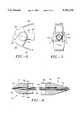
- FIG. 4is a cross sectional view of an exemplary embodiment of the proximal hub of the manual actuator according to the present invention.
- FIG. 5is a cross sectional view of another exemplary embodiment of the proximal hub of the manual actuator according to the present invention.
- FIG. 6is a fragmentary side view detail of the proximal end of the manual actuator according to the present invention.
- FIG. 7is a front view of the proximal end of the manual actuator according to the present invention.
- FIG. 8is a cross sectional view of another exemplary embodiment of the manual actuator according to the present invention, showing the proximal hub, the distal hub and the pulling wires.
- FIG. 1shows an exemplary embodiment of the manual actuator, shown generally at 200, for retracting and advancing, or operating, a therapeutic working element.
- the manual actuatorin operation, causes the retraction and advancement of the actuation shaft 212.
- the actuation shaft 212by virtue of its reciprocating movement, may also operate a blunt end member, such as is disclosed in copending U.S. Application No. XX/XXX,XXX, attorney docket number LUMN1594, commonly assigned, the specification of which is included herewith by reference in its entirety.
- the manual actuator illustrated in FIG. 1can be adapted to most any catheter apparatus whose therapeutic working element requires a low frequency, manually and selectively controlled reciprocating movement, and should not be construed as being limited to any particular type of the therapeutic working element.
- the manual actuator 200includes a hollow cylindrical retracting member 206 which has a proximal hub 218 attached to the proximal end thereof.
- FIG. 4shows a cross sectional view of one embodiment of a proximal hub according to the present invention.
- the proximal hub 218has a cylindrical base portion 219 and an integral semi-hemispherical endcap 217.
- the cylindrical base portion 219is dimensioned so as to fit snugly within the proximal open end of the hollow cylindrical retracting member 206.
- the proximate hub 218includes an axial through bore for accommodating at least the actuation shaft of the catheter system.
- the actuation shaft 212in the embodiment shown in FIG.
- a guidewire 213is arranged within the actuation shaft 212 of the catheter device, and emerges at the proximal-most point of the semi-hemispherical endcap 217.
- FIG. 5shows another exemplary embodiment of the proximal hub 218 according to the present invention.
- the actuation shaft 212is not terminated within the axial through bore of the proximal hub 218, as it is in FIG. 4. Rather, in FIG. 5, the proximal hub 218 accommodates the actuation shaft 212 along its entire longitudinal axis. Indeed, in the embodiment shown in FIG. 5, the actuation shaft 212, emerges at the proximal-most point of the semi-hemispherical endcap 217.
- the actuation shaft 212although traversing the entire length of the proximal hub 218 in the axial through bore thereof, is nevertheless secured thereto.
- the guidewire 213can be seen within the actuation shaft 212.
- the retracting member 206is fitted within the open proximal end of a hollow cylindrical bracing member 204.
- the inner diameter of the hollow cylindrical bracing member 204is slightly larger than the outer diameter of the retracting member 206, thereby allowing the retracting member 206 to fit and slide within the hollow cylindrical bracing member 204, through its open proximal end 214. In this fashion, the retracting member 206 and the bracing member 204 are free to slide against one another, in a telescoping fashion.
- the actuation shaft 212as shown in FIGS. 4 and 5, is secured to the proximal hub 218.
- the actuation shaft 212is disposed within the manual actuator, along its longitudinal axis.
- a pair of bracing member mounting pins 208is secured near the distal end of the bracing member 204, on its tubular outer surface.
- the two bracing member mounting pins 208are disposed diametrically opposite relative to one another, so as to radially project from the bracing member 204.
- the pair of bracing member pins 208may be unitarily and integrally formed, and secured proximal to the distal end of the bracing member 204.
- bracing member pins 208include a cylindrical opening therethrough, whose axis is orthogonal to the longitudinal axis of the pins 208 for snugly fitting the bracing member 204 therein.
- a pair of retracting member mounting pins 210is secured near the proximal end of the retracting member 206, on its tubular outer surface.
- the two retracting member mounting pins 210are disposed diametrically opposite one another, so as to radially project from the retracting member 206.
- the pair of retracting member pins 210may be unitarily and integrally formed, and secured near to the proximal end of the retracting member 206.
- These unitarily and integrally formed retracting member pins 210include a cylindrical opening therethrough, whose axis is orthogonal to the longitudinal axis of the pins 210 for snugly fitting the retracting member 206 therein.
- a pair of resilient connecting members 202are mounted onto the bracing member mounting pins 208 and to the retracting member mounting pins 210.
- the connecting members 202are made of thin strips of resilient material which regain their original shape after being deformed.
- One end of each of the connecting members 202is pivotally connected onto the bracing member mounting pins 208, whereas the other end of each of the connecting members 202 is pivotally connected to the retracting member mounting pins 210.
- the resilient connecting membersare mounted onto the mounting pins 208 and 210 in such a manner that, when unstressed by a manually applied external force, they exert a force in the distal direction on the retracting member 206 and a force in the proximal direction on the bracing member 204. Therefore, when unstressed by a manually applied external force, the connecting members 202 urge the retracting member 206 within the hollow interior of the bracing member 204.
- FIG. 2illustrates the forces that the connecting members 202 exert on the retracting member 206 and the bracing member 204.
- the connecting members 202act, in the absence of a manually applied external force, to exert an outward force in the direction of the arrows 220, that is, a direction which is toward and orthogonal to the bracing member 204 and the retracting member 206.
- the distal ends of the connecting members 202pivot about the bracing member mounting pins 208
- the proximal ends of the connecting members 202pivot about the retracting member mounting pins 210.
- the compressive stresses applied to the resilient connecting members 202 upon mounting them to the mounting pins 208 and 210urge the retracting member toward, and into the tubular interior hollow of the bracing member 204.
- the distal ends of the connecting members 202are pivotally mounted onto the bracing member mounting pins 208 by means of distal flanges 203 having an opening therethrough for pivotally fitting the bracing member mounting pins 210 therein.
- the proximal ends of the connecting members 202are pivotally mounted onto the retracting member mounting pins by means of proximal flanges 205 having an opening therethrough for pivotally fitting the retracting member mounting pins therein.
- the mounting pins 208, 210are at their greatest distance from one another when the degree of curvature of the connecting members 202 is at its lowest. That is, the retracting member 206 and thus the actuation shaft 212 are most retracted when the connecting members 202 are substantially parallel, under the action of the forces 224.
- the connecting members 202tend to return to their original shape, as shown in FIG. 2.
- the retracting member 206advances the actuating shaft 212 which, in turn, causes the operation or the advancement of at least a portion of the therapeutic working member.
- the manual application of the external force 224(FIG. 3), followed by its release (FIG.
- FIGS. 6 and 7show side and front views, respectively, of the proximal end of the manual actuator 200 according to the present invention.
- the proximal hub 218is fitted within the open proximal end of the retracting member 206.
- the connecting members 202are pivotally attached to the retracting member mounting pins 210 via proximal flanges 205. This pivotal attachment allows the retracting member 206 to be retracted and advanced under the influence of external forces manually applied by a physician's hand.
- the front view of FIG. 7shows the bracing member mounting pins 210 which radially project from the retracting member 206 at diametrically opposed positions relative to one another.
- the semi-hemispherical endcap 217includes an opening 238 of its axial through bore for passage of the actuating shaft 212 and the guidewire 213, or just the guidewire 213.
- FIG. 8shows a cross sectional view of both the proximal hub 218 and the distal hub 230.
- the entire lengths of the retracting member 206 and the bracing member 204are not shown in FIG. 8.
- the mounting pins 208 and 210, together with the connecting members 202 secured thereto,have also been omitted from FIG. 8, so as to clearly show the cross sections of the proximal and distal hubs 218 and 230.
- the proximal hub 218, in this exemplary embodimentincludes a cylindrical base portion 219 and an integral semi-hemispherical endcap 217.
- the actuation shaftalso emerges from the distal-most point of the distal hub 230, through the distal hub axial through bore.
- the guidewire 213is disposed within the actuation shaft 212, and emerges from the proximal end and the distal end of the proximal and distal hubs 218, 230, respectively.
- the distal hub 230in this exemplary embodiment, includes a cylindrical base portion 233 and an integral conical endcap 231.
- the cylindrical base portion 233is dimensioned so as to fit snugly within the distal open end of the hollow cylindrical bracing member 204.
- the distal hub 230includes a distal hub through bore which accommodates the actuation shaft 212 along its entire length. Indeed, in this embodiment, the distal endcap 230 is traversed along its entire length by the actuation shaft 212, which emerges at the distal-most point of the integral conical endcap 231.
- an actuation shaft of the catheter devicemay not efficiently transmit all of the forces applied to the connecting members, especially if the actuation shaft is made of a compressible or stretchable material.
- the force applied to the connecting members, and the retraction of the retracting membermay be partially or totally taken up by any slack present in a long length of actuation shaft, or by its compression or stretching.
- That roleis discharged, in the embodiment shown in FIG. 8, by one or more pulling wire 236.
- the pulling wires 236are anchored within the cylindrical base 219 of the proximal hub 218 at their proximal ends 234.
- the pulling wires 236travels adjacent to the actuation shaft and terminates at and is secured to the therapeutic working element.
- the pulling wire 236is made of any material exhibiting high tensile strength and which does not stretch or compress appreciably when tensioned.
- a suitable material for the pulling wires 236is KEVLAR, due to its high strength and its ready susceptibility to being be woven or otherwise formed into thin strands.
- the actuation shaft 212does not transmit any mechanical force to the working element, and the actuation shaft 212 is not secured within either the proximal or distal endcaps 218 and 230, respectively.
- the proximate hub of FIG. 3is equally compatible with the embodiment of the present invention depicted in FIG. 8.
- any proximal hub which anchors the pulling wire or wires 236 theretois equally compatible with the exemplary embodiment of FIG. 8, as those of skill in this art will readily recognize, and any manual actuator equipped with such proximal hubs should be deemed to fall within the scope of the present invention.
- the above descriptionis illustrative only and not limiting of the disclosed invention.
- the inventionneed not be limited to resilient connecting members made of thin strips of resilient material.
- the resilient connecting membercould be a rubber balloon connecting the distal end of the bracing member to the proximate end of the retracting member.
- the shape of the various elementscan vary from those described herein.
- the shape of the proximate and distal hubscan vary without, however, departing from the spirit of the present invention.
- the inventionis to be limited only by the claims as set forth below.
Landscapes
- Health & Medical Sciences (AREA)
- Surgery (AREA)
- Life Sciences & Earth Sciences (AREA)
- Biomedical Technology (AREA)
- Nuclear Medicine, Radiotherapy & Molecular Imaging (AREA)
- Engineering & Computer Science (AREA)
- Ophthalmology & Optometry (AREA)
- Heart & Thoracic Surgery (AREA)
- Medical Informatics (AREA)
- Molecular Biology (AREA)
- Animal Behavior & Ethology (AREA)
- General Health & Medical Sciences (AREA)
- Public Health (AREA)
- Veterinary Medicine (AREA)
- Media Introduction/Drainage Providing Device (AREA)
Abstract
Description
Claims (34)
Priority Applications (2)
| Application Number | Priority Date | Filing Date | Title |
|---|---|---|---|
| US08/808,092US5741270A (en) | 1997-02-28 | 1997-02-28 | Manual actuator for a catheter system for treating a vascular occlusion |
| PCT/US1998/002662WO1999040854A1 (en) | 1997-02-28 | 1998-02-13 | Manual actuator for a catheter system for treating a vascular occlusion |
Applications Claiming Priority (2)
| Application Number | Priority Date | Filing Date | Title |
|---|---|---|---|
| US08/808,092US5741270A (en) | 1997-02-28 | 1997-02-28 | Manual actuator for a catheter system for treating a vascular occlusion |
| PCT/US1998/002662WO1999040854A1 (en) | 1997-02-28 | 1998-02-13 | Manual actuator for a catheter system for treating a vascular occlusion |
Publications (1)
| Publication Number | Publication Date |
|---|---|
| US5741270Atrue US5741270A (en) | 1998-04-21 |
Family
ID=26793939
Family Applications (1)
| Application Number | Title | Priority Date | Filing Date |
|---|---|---|---|
| US08/808,092Expired - LifetimeUS5741270A (en) | 1997-02-28 | 1997-02-28 | Manual actuator for a catheter system for treating a vascular occlusion |
Country Status (2)
| Country | Link |
|---|---|
| US (1) | US5741270A (en) |
| WO (1) | WO1999040854A1 (en) |
Cited By (86)
| Publication number | Priority date | Publication date | Assignee | Title |
|---|---|---|---|---|
| US5989263A (en)* | 1998-03-11 | 1999-11-23 | Arteria Medical Science L.L.C. | Hydraulically actuated dilatation mechanism for vessel dilatation and vascular prosthesis delivery and methods of use |
| US6168616B1 (en)* | 1997-06-02 | 2001-01-02 | Global Vascular Concepts | Manually expandable stent |
| US6217527B1 (en) | 1998-09-30 | 2001-04-17 | Lumend, Inc. | Methods and apparatus for crossing vascular occlusions |
| US6231546B1 (en)* | 1998-01-13 | 2001-05-15 | Lumend, Inc. | Methods and apparatus for crossing total occlusions in blood vessels |
| WO2001074255A1 (en) | 2000-03-31 | 2001-10-11 | Bacchus Vascular Inc. | Expansible shearing catheters for thrombus and occlusive material removal |
| US20020022788A1 (en)* | 1999-08-19 | 2002-02-21 | Tim Corvi | Apparatus and methods for material capture and removal |
| DE20121029U1 (en) | 2001-12-28 | 2002-04-04 | Pommerrenig, Annemarie, 60528 Frankfurt | Self-anchoring wound spreader |
| US20020077642A1 (en)* | 2000-12-20 | 2002-06-20 | Fox Hollow Technologies, Inc. | Debulking catheter |
| US6506178B1 (en) | 2000-11-10 | 2003-01-14 | Vascular Architects, Inc. | Apparatus and method for crossing a position along a tubular body structure |
| US6514261B1 (en) | 1998-09-30 | 2003-02-04 | Impra, Inc. | Delivery mechanism for implantable stent |
| US6554843B1 (en)* | 2001-10-15 | 2003-04-29 | Universal Optical Co., Ltd. | Cataract instrument |
| US6561998B1 (en) | 1998-04-07 | 2003-05-13 | Transvascular, Inc. | Transluminal devices, systems and methods for enlarging interstitial penetration tracts |
| US20030120295A1 (en)* | 2000-12-20 | 2003-06-26 | Fox Hollow Technologies, Inc. | Debulking catheters and methods |
| US20030125758A1 (en)* | 2000-12-20 | 2003-07-03 | Fox Hollow Technologies, Inc. | Debulking catheters and methods |
| US20030125757A1 (en)* | 2000-12-20 | 2003-07-03 | Fox Hollow Technologies, Inc. | Debulking catheters and methods |
| US20040167554A1 (en)* | 2000-12-20 | 2004-08-26 | Fox Hollow Technologies, Inc. | Methods and devices for reentering a true lumen from a subintimal space |
| US20040167553A1 (en)* | 2000-12-20 | 2004-08-26 | Fox Hollow Technologies, Inc. | Methods and devices for cutting tissue |
| US20040220604A1 (en)* | 2003-04-30 | 2004-11-04 | Fogarty Thomas J. | Tissue separation apparatus and method |
| US20050154407A1 (en)* | 2000-12-20 | 2005-07-14 | Fox Hollow Technologies, Inc. | Method of evaluating drug efficacy for treating atherosclerosis |
| US20050171478A1 (en)* | 1998-01-13 | 2005-08-04 | Selmon Matthew R. | Catheter system for crossing total occlusions in vasculature |
| US20050177068A1 (en)* | 2000-12-20 | 2005-08-11 | Fox Hollow Technologies, Inc. | Debulking catheters and methods |
| US20050222594A1 (en)* | 2004-03-31 | 2005-10-06 | Siemens Aktiengesellschaft | Catheter device for applying a medical cutting balloon intervention |
| US20050222663A1 (en)* | 2000-12-20 | 2005-10-06 | Fox Hollow Technologies, Inc. | Debulking catheters and methods |
| US20050222595A1 (en)* | 2004-03-31 | 2005-10-06 | Siemens Aktiengesellschaft | Device for removing a total vascular occlusion with OCT monitoring |
| US20050234343A1 (en)* | 2004-03-31 | 2005-10-20 | Siemens Aktiengesellschaft | Medical device for removing a vascular occlusion |
| US7004957B1 (en) | 1999-02-05 | 2006-02-28 | Syclix Limited | Actuating and locking mechanism for a surgical tool |
| US7004173B2 (en) | 2000-12-05 | 2006-02-28 | Lumend, Inc. | Catheter system for vascular re-entry from a sub-intimal space |
| US20060236019A1 (en)* | 2005-04-19 | 2006-10-19 | Fox Hollow Technologies, Inc. | Libraries and data structures of materials removed by debulking catheters |
| US20060235366A1 (en)* | 2000-12-20 | 2006-10-19 | Fox Hollow Technologies, Inc. | Method of evaluating a treatment for vascular disease |
| US20060239982A1 (en)* | 2000-12-20 | 2006-10-26 | Fox Hollow Technologies, Inc. | Debulking catheters and methods |
| US20070032808A1 (en)* | 2005-08-03 | 2007-02-08 | Azam Anwar | System and method for addressing total occlusion in a vascular environment |
| US20070038173A1 (en)* | 2005-07-27 | 2007-02-15 | Fox Hollow Technologies, Inc. | Methods affecting markers in patients having vascular disease |
| US20070078469A1 (en)* | 2000-12-20 | 2007-04-05 | Fox Hollow Technologies, Inc | Testing a patient population having a cardiovascular condition for drug efficacy |
| US20070083220A1 (en)* | 2004-06-09 | 2007-04-12 | Ovalum Ltd. | Blood vessel occlusion auger |
| US20070093780A1 (en)* | 2005-09-12 | 2007-04-26 | Kugler Chad J | Endovascular devices and methods for exploiting intramural space |
| US20070093783A1 (en)* | 2005-09-12 | 2007-04-26 | Kugler Chad J | Endovascular devices and methods |
| US20070093782A1 (en)* | 2005-09-12 | 2007-04-26 | Kugler Chad J | Endovascular devices and methods |
| US20070093781A1 (en)* | 2005-09-12 | 2007-04-26 | Kugler Chad J | Endovascular devices and methods for exploiting intramural space |
| US20070196926A1 (en)* | 2006-02-17 | 2007-08-23 | Fox Hollow Technologies, Inc. | Testing lumenectomy samples for Markers of non-vascular diseases |
| US20080125805A1 (en)* | 1999-12-09 | 2008-05-29 | Mische Hans A | Method and devices for the treatment of nasal sinus disorders |
| US20080146918A1 (en)* | 2005-02-08 | 2008-06-19 | Magnin Paul A | Apparatus and methods for low-cost intravascular ultrasound imaging and for crossing severe vascular occlusions |
| US20080228171A1 (en)* | 2006-11-21 | 2008-09-18 | Kugler Chad J | Endovascular devices and methods for exploiting intramural space |
| US20090105653A1 (en)* | 2007-10-17 | 2009-04-23 | Gardia Medical Ltd | Guidewire stop |
| US20090124899A1 (en)* | 2007-10-22 | 2009-05-14 | Peter Alan Jacobs | Methods and devices for crossing chronic total occlusions |
| US20090171433A1 (en)* | 2007-12-27 | 2009-07-02 | Cook Incorporated | Control handle |
| US20090182363A1 (en)* | 2006-09-19 | 2009-07-16 | Ovalum Ltd. | Blood vessel occlusion auger |
| US20090270890A1 (en)* | 2008-04-28 | 2009-10-29 | David Bryan Robinson | Methods and apparatus for crossing occlusions in blood vessels |
| US20110236902A1 (en)* | 2004-12-13 | 2011-09-29 | Tyco Healthcare Group Lp | Testing a patient population having a cardiovascular condition for drug efficacy |
| US8192452B2 (en) | 2009-05-14 | 2012-06-05 | Tyco Healthcare Group Lp | Easily cleaned atherectomy catheters and methods of use |
| US8202246B2 (en) | 2008-02-05 | 2012-06-19 | Bridgepoint Medical, Inc. | Crossing occlusions in blood vessels |
| US8246640B2 (en) | 2003-04-22 | 2012-08-21 | Tyco Healthcare Group Lp | Methods and devices for cutting tissue at a vascular location |
| US8328829B2 (en) | 1999-08-19 | 2012-12-11 | Covidien Lp | High capacity debulking catheter with razor edge cutting window |
| US8337425B2 (en) | 2008-02-05 | 2012-12-25 | Bridgepoint Medical, Inc. | Endovascular device with a tissue piercing distal probe and associated methods |
| US8414604B2 (en) | 2008-10-13 | 2013-04-09 | Covidien Lp | Devices and methods for manipulating a catheter shaft |
| US8496677B2 (en) | 2009-12-02 | 2013-07-30 | Covidien Lp | Methods and devices for cutting tissue |
| US8597315B2 (en) | 1999-08-19 | 2013-12-03 | Covidien Lp | Atherectomy catheter with first and second imaging devices |
| US8652193B2 (en) | 2005-05-09 | 2014-02-18 | Angiomed Gmbh & Co. Medizintechnik Kg | Implant delivery device |
| US8784440B2 (en) | 2008-02-25 | 2014-07-22 | Covidien Lp | Methods and devices for cutting tissue |
| US8808186B2 (en) | 2010-11-11 | 2014-08-19 | Covidien Lp | Flexible debulking catheters with imaging and methods of use and manufacture |
| US20140276612A1 (en)* | 2013-03-13 | 2014-09-18 | Matthew W. Sevensma | Steerable catheters |
| WO2014202243A1 (en)* | 2013-06-21 | 2014-12-24 | Novartis Ag | Systems and techniques for tissue manipulation during ocular surgery |
| US8920450B2 (en) | 2010-10-28 | 2014-12-30 | Covidien Lp | Material removal device and method of use |
| US8992717B2 (en) | 2011-09-01 | 2015-03-31 | Covidien Lp | Catheter with helical drive shaft and methods of manufacture |
| US9028512B2 (en) | 2009-12-11 | 2015-05-12 | Covidien Lp | Material removal device having improved material capture efficiency and methods of use |
| US9060802B2 (en) | 2006-11-21 | 2015-06-23 | Bridgepoint Medical, Inc. | Endovascular devices and methods for exploiting intramural space |
| US9119662B2 (en) | 2010-06-14 | 2015-09-01 | Covidien Lp | Material removal device and method of use |
| US9192500B1 (en) | 2015-01-29 | 2015-11-24 | Intact Vascular, Inc. | Delivery device and method of delivery |
| US9375336B1 (en) | 2015-01-29 | 2016-06-28 | Intact Vascular, Inc. | Delivery device and method of delivery |
| US9433520B2 (en) | 2015-01-29 | 2016-09-06 | Intact Vascular, Inc. | Delivery device and method of delivery |
| US9456914B2 (en) | 2015-01-29 | 2016-10-04 | Intact Vascular, Inc. | Delivery device and method of delivery |
| US9532844B2 (en) | 2012-09-13 | 2017-01-03 | Covidien Lp | Cleaning device for medical instrument and method of use |
| US9687266B2 (en) | 2009-04-29 | 2017-06-27 | Covidien Lp | Methods and devices for cutting and abrading tissue |
| US9801647B2 (en) | 2006-05-26 | 2017-10-31 | Covidien Lp | Catheter including cutting element and energy emitting element |
| US9943329B2 (en) | 2012-11-08 | 2018-04-17 | Covidien Lp | Tissue-removing catheter with rotatable cutter |
| TWI643598B (en)* | 2013-06-21 | 2018-12-11 | 瑞士商諾華公司 | Systems and techniques for tissue manipulation during ocular surgery |
| US10213224B2 (en) | 2014-06-27 | 2019-02-26 | Covidien Lp | Cleaning device for catheter and catheter including the same |
| US10292721B2 (en) | 2015-07-20 | 2019-05-21 | Covidien Lp | Tissue-removing catheter including movable distal tip |
| US10314667B2 (en) | 2015-03-25 | 2019-06-11 | Covidien Lp | Cleaning device for cleaning medical instrument |
| US10314664B2 (en) | 2015-10-07 | 2019-06-11 | Covidien Lp | Tissue-removing catheter and tissue-removing element with depth stop |
| US10993824B2 (en) | 2016-01-01 | 2021-05-04 | Intact Vascular, Inc. | Delivery device and method of delivery |
| US11020141B2 (en) | 2005-09-12 | 2021-06-01 | Bridgepoint Medical, Inc. | Endovascular devices and methods |
| CN113274066A (en)* | 2020-01-31 | 2021-08-20 | 德普伊新特斯产品公司 | System for assisting in the delivery of a mechanical endovascular therapy device |
| US11298511B2 (en) | 2006-11-21 | 2022-04-12 | Bridgepoint Medical, Inc. | Endovascular devices and methods for exploiting intramural space |
| US11375794B1 (en)* | 2018-12-04 | 2022-07-05 | Studio 010 Inc. | Device for pulling nose and ear hair |
| US11660218B2 (en) | 2017-07-26 | 2023-05-30 | Intact Vascular, Inc. | Delivery device and method of delivery |
| US11992238B2 (en) | 2008-02-05 | 2024-05-28 | Boston Scientific Scimed, Inc. | Endovascular device with a tissue piercing distal probe and associated methods |
Citations (16)
| Publication number | Priority date | Publication date | Assignee | Title |
|---|---|---|---|---|
| US3640270A (en)* | 1969-08-02 | 1972-02-08 | Niess Elektromed Ingeborg | Electric contactor with venturi-suction means for organic tissue |
| US4355643A (en)* | 1980-03-05 | 1982-10-26 | University Of Iowa Research Foundation | Vacuum cup doppler flow transducer and method for using same |
| US4541433A (en)* | 1984-06-01 | 1985-09-17 | Medtronic, Inc. | Cardiac output monitor |
| US4698057A (en)* | 1986-06-09 | 1987-10-06 | Joishy Suresh K | Built in assembly for stabilizing and securing intravascular needle or catheter like device |
| US5102390A (en)* | 1985-05-02 | 1992-04-07 | C. R. Bard, Inc. | Microdilatation probe and system for performing angioplasty in highly stenosed blood vessels |
| US5193546A (en)* | 1991-05-15 | 1993-03-16 | Alexander Shaknovich | Coronary intravascular ultrasound imaging method and apparatus |
| US5282817A (en)* | 1992-09-08 | 1994-02-01 | Hoogeboom Thomas J | Actuating handle for multipurpose surgical instrument |
| US5308357A (en)* | 1992-08-21 | 1994-05-03 | Microsurge, Inc. | Handle mechanism for manual instruments |
| US5321501A (en)* | 1991-04-29 | 1994-06-14 | Massachusetts Institute Of Technology | Method and apparatus for optical imaging with means for controlling the longitudinal range of the sample |
| US5336252A (en)* | 1992-06-22 | 1994-08-09 | Cohen Donald M | System and method for implanting cardiac electrical leads |
| US5355871A (en)* | 1992-09-11 | 1994-10-18 | Dexide, Inc. | Elastomeric controller for endoscopic surgical instruments |
| US5383467A (en)* | 1992-11-18 | 1995-01-24 | Spectrascience, Inc. | Guidewire catheter and apparatus for diagnostic imaging |
| US5423846A (en)* | 1991-10-21 | 1995-06-13 | Cathco, Inc. | Dottering auger catheter system |
| US5439000A (en)* | 1992-11-18 | 1995-08-08 | Spectrascience, Inc. | Method of diagnosing tissue with guidewire |
| US5484412A (en)* | 1994-04-19 | 1996-01-16 | Pierpont; Brien E. | Angioplasty method and means for performing angioplasty |
| US5507295A (en)* | 1992-07-01 | 1996-04-16 | British Technology Group Limited | Medical devices |
Family Cites Families (8)
| Publication number | Priority date | Publication date | Assignee | Title |
|---|---|---|---|---|
| JPS5176120A (en)* | 1974-12-27 | 1976-07-01 | Showa Aluminium Co Ltd | |
| US5133727A (en)* | 1990-05-10 | 1992-07-28 | Symbiosis Corporation | Radial jaw biopsy forceps |
| US4572186A (en)* | 1983-12-07 | 1986-02-25 | Cordis Corporation | Vessel dilation |
| US5192290A (en)* | 1990-08-29 | 1993-03-09 | Applied Medical Resources, Inc. | Embolectomy catheter |
| AU660444B2 (en)* | 1991-02-15 | 1995-06-29 | Ingemar H. Lundquist | Torquable catheter and method |
| US5522819A (en)* | 1994-05-12 | 1996-06-04 | Target Therapeutics, Inc. | Dual coil medical retrieval device |
| DE4429117A1 (en)* | 1994-08-17 | 1996-02-22 | Bess Medizintechnik Gmbh | Dilatation catheter for vessel or tissue restrictions |
| WO1996011636A1 (en)* | 1994-10-18 | 1996-04-25 | Kieturakis Maciej J | Endoscopic surgical instrument |
- 1997
- 1997-02-28USUS08/808,092patent/US5741270A/ennot_activeExpired - Lifetime
- 1998
- 1998-02-13WOPCT/US1998/002662patent/WO1999040854A1/enactiveApplication Filing
Patent Citations (17)
| Publication number | Priority date | Publication date | Assignee | Title |
|---|---|---|---|---|
| US3640270A (en)* | 1969-08-02 | 1972-02-08 | Niess Elektromed Ingeborg | Electric contactor with venturi-suction means for organic tissue |
| US4355643A (en)* | 1980-03-05 | 1982-10-26 | University Of Iowa Research Foundation | Vacuum cup doppler flow transducer and method for using same |
| US4541433A (en)* | 1984-06-01 | 1985-09-17 | Medtronic, Inc. | Cardiac output monitor |
| US5102390A (en)* | 1985-05-02 | 1992-04-07 | C. R. Bard, Inc. | Microdilatation probe and system for performing angioplasty in highly stenosed blood vessels |
| US4698057A (en)* | 1986-06-09 | 1987-10-06 | Joishy Suresh K | Built in assembly for stabilizing and securing intravascular needle or catheter like device |
| US5321501A (en)* | 1991-04-29 | 1994-06-14 | Massachusetts Institute Of Technology | Method and apparatus for optical imaging with means for controlling the longitudinal range of the sample |
| US5459570A (en)* | 1991-04-29 | 1995-10-17 | Massachusetts Institute Of Technology | Method and apparatus for performing optical measurements |
| US5193546A (en)* | 1991-05-15 | 1993-03-16 | Alexander Shaknovich | Coronary intravascular ultrasound imaging method and apparatus |
| US5423846A (en)* | 1991-10-21 | 1995-06-13 | Cathco, Inc. | Dottering auger catheter system |
| US5336252A (en)* | 1992-06-22 | 1994-08-09 | Cohen Donald M | System and method for implanting cardiac electrical leads |
| US5507295A (en)* | 1992-07-01 | 1996-04-16 | British Technology Group Limited | Medical devices |
| US5308357A (en)* | 1992-08-21 | 1994-05-03 | Microsurge, Inc. | Handle mechanism for manual instruments |
| US5282817A (en)* | 1992-09-08 | 1994-02-01 | Hoogeboom Thomas J | Actuating handle for multipurpose surgical instrument |
| US5355871A (en)* | 1992-09-11 | 1994-10-18 | Dexide, Inc. | Elastomeric controller for endoscopic surgical instruments |
| US5383467A (en)* | 1992-11-18 | 1995-01-24 | Spectrascience, Inc. | Guidewire catheter and apparatus for diagnostic imaging |
| US5439000A (en)* | 1992-11-18 | 1995-08-08 | Spectrascience, Inc. | Method of diagnosing tissue with guidewire |
| US5484412A (en)* | 1994-04-19 | 1996-01-16 | Pierpont; Brien E. | Angioplasty method and means for performing angioplasty |
Cited By (220)
| Publication number | Priority date | Publication date | Assignee | Title |
|---|---|---|---|---|
| US6168616B1 (en)* | 1997-06-02 | 2001-01-02 | Global Vascular Concepts | Manually expandable stent |
| US6514217B1 (en) | 1998-01-13 | 2003-02-04 | Lumend, Inc. | Methods and apparatus for treating vascular occlusions |
| US6511458B2 (en) | 1998-01-13 | 2003-01-28 | Lumend, Inc. | Vascular re-entry catheter |
| US6221049B1 (en) | 1998-01-13 | 2001-04-24 | Lumend, Inc. | Methods and apparatus for crossing vascular occlusions |
| US6231546B1 (en)* | 1998-01-13 | 2001-05-15 | Lumend, Inc. | Methods and apparatus for crossing total occlusions in blood vessels |
| US6235000B1 (en) | 1998-01-13 | 2001-05-22 | Lumend, Inc. | Apparatus for crossing total occlusion in blood vessels |
| US20050171478A1 (en)* | 1998-01-13 | 2005-08-04 | Selmon Matthew R. | Catheter system for crossing total occlusions in vasculature |
| US5989263A (en)* | 1998-03-11 | 1999-11-23 | Arteria Medical Science L.L.C. | Hydraulically actuated dilatation mechanism for vessel dilatation and vascular prosthesis delivery and methods of use |
| US6561998B1 (en) | 1998-04-07 | 2003-05-13 | Transvascular, Inc. | Transluminal devices, systems and methods for enlarging interstitial penetration tracts |
| US6217527B1 (en) | 1998-09-30 | 2001-04-17 | Lumend, Inc. | Methods and apparatus for crossing vascular occlusions |
| US7122050B2 (en) | 1998-09-30 | 2006-10-17 | Bard Peripheral Vascular, Inc. | Delivery mechanism for implantable stent |
| US8852266B2 (en) | 1998-09-30 | 2014-10-07 | Bard Peripheral Vascular, Inc. | Delivery mechanism for implantable stent |
| US20070032860A1 (en)* | 1998-09-30 | 2007-02-08 | Brooks Christopher J | Delivery mechanism for implantable stent |
| US20030144671A1 (en)* | 1998-09-30 | 2003-07-31 | Brooks Christopher J. | Delivery mechanism for implantable stents-grafts |
| US6514261B1 (en) | 1998-09-30 | 2003-02-04 | Impra, Inc. | Delivery mechanism for implantable stent |
| US7004957B1 (en) | 1999-02-05 | 2006-02-28 | Syclix Limited | Actuating and locking mechanism for a surgical tool |
| US8784333B2 (en) | 1999-08-19 | 2014-07-22 | Covidien Lp | Apparatus and methods for material capture and removal |
| US10022145B2 (en) | 1999-08-19 | 2018-07-17 | Covidien Lp | Methods and devices for cutting tissue |
| US20090187203A1 (en)* | 1999-08-19 | 2009-07-23 | Fox Hollow Technologies, Inc. | Apparatus and methods for material capture and removal |
| US8328829B2 (en) | 1999-08-19 | 2012-12-11 | Covidien Lp | High capacity debulking catheter with razor edge cutting window |
| US8597315B2 (en) | 1999-08-19 | 2013-12-03 | Covidien Lp | Atherectomy catheter with first and second imaging devices |
| US20020022788A1 (en)* | 1999-08-19 | 2002-02-21 | Tim Corvi | Apparatus and methods for material capture and removal |
| US9486237B2 (en) | 1999-08-19 | 2016-11-08 | Covidien Lp | Methods and devices for cutting tissue |
| US8911459B2 (en) | 1999-08-19 | 2014-12-16 | Covidien Lp | Debulking catheters and methods |
| US8998937B2 (en) | 1999-08-19 | 2015-04-07 | Covidien Lp | Methods and devices for cutting tissue |
| US9788854B2 (en) | 1999-08-19 | 2017-10-17 | Covidien Lp | Debulking catheters and methods |
| US9532799B2 (en) | 1999-08-19 | 2017-01-03 | Covidien Lp | Method and devices for cutting tissue |
| US9615850B2 (en) | 1999-08-19 | 2017-04-11 | Covidien Lp | Atherectomy catheter with aligned imager |
| US20120226362A1 (en)* | 1999-12-09 | 2012-09-06 | Mische Hans A | Method and devices for the treatment of bone fractures |
| US9351772B2 (en) | 1999-12-09 | 2016-05-31 | Hans A. Mische | Method and devices for the treatment of nasal sinus disorders |
| US20080125805A1 (en)* | 1999-12-09 | 2008-05-29 | Mische Hans A | Method and devices for the treatment of nasal sinus disorders |
| WO2001074255A1 (en) | 2000-03-31 | 2001-10-11 | Bacchus Vascular Inc. | Expansible shearing catheters for thrombus and occlusive material removal |
| US6506178B1 (en) | 2000-11-10 | 2003-01-14 | Vascular Architects, Inc. | Apparatus and method for crossing a position along a tubular body structure |
| US7004173B2 (en) | 2000-12-05 | 2006-02-28 | Lumend, Inc. | Catheter system for vascular re-entry from a sub-intimal space |
| US20040167553A1 (en)* | 2000-12-20 | 2004-08-26 | Fox Hollow Technologies, Inc. | Methods and devices for cutting tissue |
| US8469979B2 (en) | 2000-12-20 | 2013-06-25 | Covidien Lp | High capacity debulking catheter with distal driven cutting wheel |
| US20060235366A1 (en)* | 2000-12-20 | 2006-10-19 | Fox Hollow Technologies, Inc. | Method of evaluating a treatment for vascular disease |
| US20060239982A1 (en)* | 2000-12-20 | 2006-10-26 | Fox Hollow Technologies, Inc. | Debulking catheters and methods |
| US7708749B2 (en) | 2000-12-20 | 2010-05-04 | Fox Hollow Technologies, Inc. | Debulking catheters and methods |
| US20030125758A1 (en)* | 2000-12-20 | 2003-07-03 | Fox Hollow Technologies, Inc. | Debulking catheters and methods |
| US7713279B2 (en) | 2000-12-20 | 2010-05-11 | Fox Hollow Technologies, Inc. | Method and devices for cutting tissue |
| US20070078469A1 (en)* | 2000-12-20 | 2007-04-05 | Fox Hollow Technologies, Inc | Testing a patient population having a cardiovascular condition for drug efficacy |
| US20100121360A9 (en)* | 2000-12-20 | 2010-05-13 | Fox Hollow Technologies, Inc | Testing a patient population having a cardiovascular condition for drug efficacy |
| US20050154407A1 (en)* | 2000-12-20 | 2005-07-14 | Fox Hollow Technologies, Inc. | Method of evaluating drug efficacy for treating atherosclerosis |
| US20050222663A1 (en)* | 2000-12-20 | 2005-10-06 | Fox Hollow Technologies, Inc. | Debulking catheters and methods |
| US7699790B2 (en) | 2000-12-20 | 2010-04-20 | Ev3, Inc. | Debulking catheters and methods |
| US20040167554A1 (en)* | 2000-12-20 | 2004-08-26 | Fox Hollow Technologies, Inc. | Methods and devices for reentering a true lumen from a subintimal space |
| US9241733B2 (en) | 2000-12-20 | 2016-01-26 | Covidien Lp | Debulking catheter |
| US20030120295A1 (en)* | 2000-12-20 | 2003-06-26 | Fox Hollow Technologies, Inc. | Debulking catheters and methods |
| US20020077642A1 (en)* | 2000-12-20 | 2002-06-20 | Fox Hollow Technologies, Inc. | Debulking catheter |
| US20030125757A1 (en)* | 2000-12-20 | 2003-07-03 | Fox Hollow Technologies, Inc. | Debulking catheters and methods |
| US7771444B2 (en) | 2000-12-20 | 2010-08-10 | Fox Hollow Technologies, Inc. | Methods and devices for removing material from a body lumen |
| US8226674B2 (en) | 2000-12-20 | 2012-07-24 | Tyco Healthcare Group Lp | Debulking catheters and methods |
| US8052704B2 (en) | 2000-12-20 | 2011-11-08 | Foxhollow Technologies, Inc. | High capacity debulking catheter with distal driven cutting wheel |
| US7927784B2 (en) | 2000-12-20 | 2011-04-19 | Ev3 | Vascular lumen debulking catheters and methods |
| US20050177068A1 (en)* | 2000-12-20 | 2005-08-11 | Fox Hollow Technologies, Inc. | Debulking catheters and methods |
| US7887556B2 (en) | 2000-12-20 | 2011-02-15 | Fox Hollow Technologies, Inc. | Debulking catheters and methods |
| US6554843B1 (en)* | 2001-10-15 | 2003-04-29 | Universal Optical Co., Ltd. | Cataract instrument |
| DE20121029U1 (en) | 2001-12-28 | 2002-04-04 | Pommerrenig, Annemarie, 60528 Frankfurt | Self-anchoring wound spreader |
| US9999438B2 (en) | 2003-04-22 | 2018-06-19 | Covidien Lp | Methods and devices for cutting tissue at a vascular location |
| US8246640B2 (en) | 2003-04-22 | 2012-08-21 | Tyco Healthcare Group Lp | Methods and devices for cutting tissue at a vascular location |
| US8961546B2 (en) | 2003-04-22 | 2015-02-24 | Covidien Lp | Methods and devices for cutting tissue at a vascular location |
| US20060206125A1 (en)* | 2003-04-30 | 2006-09-14 | Fogarty Thomas J | Tissue separation apparatus and method |
| US20040220604A1 (en)* | 2003-04-30 | 2004-11-04 | Fogarty Thomas J. | Tissue separation apparatus and method |
| DE102004015641B3 (en)* | 2004-03-31 | 2006-03-09 | Siemens Ag | Device for elimination of complete occlusion with IVUS monitoring |
| US20050234343A1 (en)* | 2004-03-31 | 2005-10-20 | Siemens Aktiengesellschaft | Medical device for removing a vascular occlusion |
| US7637885B2 (en)* | 2004-03-31 | 2009-12-29 | Siemens Aktiengesellschaft | Catheter device for applying a medical cutting balloon intervention |
| US7993361B2 (en) | 2004-03-31 | 2011-08-09 | Siemens Aktiengesellschaft | Device for removing a total vascular occlusion with OCT monitoring |
| US20050222595A1 (en)* | 2004-03-31 | 2005-10-06 | Siemens Aktiengesellschaft | Device for removing a total vascular occlusion with OCT monitoring |
| US20050222594A1 (en)* | 2004-03-31 | 2005-10-06 | Siemens Aktiengesellschaft | Catheter device for applying a medical cutting balloon intervention |
| US7704210B2 (en) | 2004-03-31 | 2010-04-27 | Siemens Aktiengesellschaft | Medical device for removing a vascular occlusion |
| RU2378996C2 (en)* | 2004-06-09 | 2010-01-20 | Овалум Лтд. | Drill for passing blood-vessel occlusions |
| US7803169B2 (en) | 2004-06-09 | 2010-09-28 | Ovalum Ltd. | Blood vessel occlusion auger |
| US20110009889A1 (en)* | 2004-06-09 | 2011-01-13 | Ovalum Ltd. | Blood vessel occlusion auger |
| JP2008504940A (en)* | 2004-06-09 | 2008-02-21 | オバラム株式会社 | Vascular occlusion auger |
| WO2005120628A3 (en)* | 2004-06-09 | 2007-07-26 | Ovalum Ltd | Blood vessel occlusion auger |
| CN101262903B (en)* | 2004-06-09 | 2012-02-01 | 欧瓦勒姆有限公司 | Blood vessel occlusion auger |
| US20070083220A1 (en)* | 2004-06-09 | 2007-04-12 | Ovalum Ltd. | Blood vessel occlusion auger |
| US20110236902A1 (en)* | 2004-12-13 | 2011-09-29 | Tyco Healthcare Group Lp | Testing a patient population having a cardiovascular condition for drug efficacy |
| US20080146918A1 (en)* | 2005-02-08 | 2008-06-19 | Magnin Paul A | Apparatus and methods for low-cost intravascular ultrasound imaging and for crossing severe vascular occlusions |
| US8007440B2 (en) | 2005-02-08 | 2011-08-30 | Volcano Corporation | Apparatus and methods for low-cost intravascular ultrasound imaging and for crossing severe vascular occlusions |
| US9474506B2 (en) | 2005-02-08 | 2016-10-25 | Volcano Corporation | Apparatus and methods for low-cost intravascular ultrasound imaging and for crossing severe vascular occlusions |
| US8480593B2 (en) | 2005-02-08 | 2013-07-09 | Volcano Corporation | Apparatus and methods for intravascular ultrasound imaging and for crossing severe vascular occlusions |
| US7794413B2 (en) | 2005-04-19 | 2010-09-14 | Ev3, Inc. | Libraries and data structures of materials removed by debulking catheters |
| US20060236019A1 (en)* | 2005-04-19 | 2006-10-19 | Fox Hollow Technologies, Inc. | Libraries and data structures of materials removed by debulking catheters |
| US8652193B2 (en) | 2005-05-09 | 2014-02-18 | Angiomed Gmbh & Co. Medizintechnik Kg | Implant delivery device |
| US20070038173A1 (en)* | 2005-07-27 | 2007-02-15 | Fox Hollow Technologies, Inc. | Methods affecting markers in patients having vascular disease |
| US20070032808A1 (en)* | 2005-08-03 | 2007-02-08 | Azam Anwar | System and method for addressing total occlusion in a vascular environment |
| US8025655B2 (en) | 2005-09-12 | 2011-09-27 | Bridgepoint Medical, Inc. | Endovascular devices and methods |
| US7938819B2 (en) | 2005-09-12 | 2011-05-10 | Bridgepoint Medical, Inc. | Endovascular devices and methods |
| US12161358B2 (en) | 2005-09-12 | 2024-12-10 | Boston Scientific Scimed, Inc. | Endovascular devices and methods |
| US12251128B2 (en) | 2005-09-12 | 2025-03-18 | Boston Scientific Scimed, Inc. | Endovascular devices and methods for exploiting intramural space |
| US8323261B2 (en) | 2005-09-12 | 2012-12-04 | Bridgepoint Medical, Inc. | Methods of accessing an intramural space |
| US12295597B2 (en) | 2005-09-12 | 2025-05-13 | Boston Scientific Scimed, Inc. | Endovascular devices and methods for exploiting intramural space |
| US11826070B2 (en) | 2005-09-12 | 2023-11-28 | Boston Scientific Scimed, Inc. | Endovascular devices and methods |
| US11793978B2 (en) | 2005-09-12 | 2023-10-24 | Boston Scientific Scimed, Inc. | Endovascular devices and methods |
| US20070093781A1 (en)* | 2005-09-12 | 2007-04-26 | Kugler Chad J | Endovascular devices and methods for exploiting intramural space |
| US8083727B2 (en) | 2005-09-12 | 2011-12-27 | Bridgepoint Medical, Inc. | Endovascular devices and methods for exploiting intramural space |
| US11779361B2 (en) | 2005-09-12 | 2023-10-10 | Boston Scientific Scimed, Inc. | Endovascular devices and methods for exploiting intramural space |
| US9788855B2 (en) | 2005-09-12 | 2017-10-17 | Bridgepoint Medical, Inc. | Endovascular devices and methods for exploiting intramural space |
| US8512310B2 (en) | 2005-09-12 | 2013-08-20 | Bridgepoint Medical, Inc. | Endovascular devices and methods for exploiting intramural space |
| US11607245B2 (en) | 2005-09-12 | 2023-03-21 | Boston Scientific Scimed, Inc. | Endovascular devices and methods for exploiting intramural space |
| US20070093779A1 (en)* | 2005-09-12 | 2007-04-26 | Kugler Chad J | Endovascular devices and methods |
| US7918870B2 (en) | 2005-09-12 | 2011-04-05 | Bridgepoint Medical, Inc. | Endovascular devices and methods |
| US8636712B2 (en) | 2005-09-12 | 2014-01-28 | Bridgepoint Medical, Inc. | Endovascular devices and methods |
| US12214144B2 (en) | 2005-09-12 | 2025-02-04 | Boston Scientific Scimed, Inc. | Endovascular devices and methods |
| US11229776B2 (en) | 2005-09-12 | 2022-01-25 | Bridgepoint Medical, Inc. | Endovascular devices and methods |
| US20070093782A1 (en)* | 2005-09-12 | 2007-04-26 | Kugler Chad J | Endovascular devices and methods |
| US11076882B2 (en) | 2005-09-12 | 2021-08-03 | Bridgepoint Medical, Inc. | Endovascular devices and methods |
| US11020141B2 (en) | 2005-09-12 | 2021-06-01 | Bridgepoint Medical, Inc. | Endovascular devices and methods |
| US10939928B2 (en) | 2005-09-12 | 2021-03-09 | Bridgepoint Medical, Inc. | Endovascular devices and methods for exploiting intramural space |
| US20070093783A1 (en)* | 2005-09-12 | 2007-04-26 | Kugler Chad J | Endovascular devices and methods |
| US20070093780A1 (en)* | 2005-09-12 | 2007-04-26 | Kugler Chad J | Endovascular devices and methods for exploiting intramural space |
| US9308019B2 (en) | 2005-09-12 | 2016-04-12 | Bridgepoint Medical, Inc. | Endovascular devices and methods for exploiting intramural space |
| US10806487B2 (en) | 2005-09-12 | 2020-10-20 | Bridgepoint Medical, Inc. | Endovascular devices and methods for exploiting intramural space |
| US8961494B2 (en) | 2005-09-12 | 2015-02-24 | Bridgepoint Medical, Inc. | Endovascular devices and methods for exploiting intramural space |
| US9237897B2 (en) | 2005-09-12 | 2016-01-19 | Bridgepoint Medical, Inc. | Endovascular devices and methods |
| US10143487B2 (en) | 2005-09-12 | 2018-12-04 | Bridgepoint Medical, Inc. | Endovascular devices and methods |
| US10166035B2 (en) | 2005-09-12 | 2019-01-01 | Bridgepoint Medical, Inc. | Endovascular devices and methods for exploiting intramural space |
| US10315010B2 (en) | 2005-09-12 | 2019-06-11 | Bridgepoint Medical, Inc. | Endovascular devices and methods |
| US10342569B2 (en) | 2005-09-12 | 2019-07-09 | Bridgeport Medical, Inc. | Endovascular devices and methods |
| US20070196926A1 (en)* | 2006-02-17 | 2007-08-23 | Fox Hollow Technologies, Inc. | Testing lumenectomy samples for Markers of non-vascular diseases |
| US7989207B2 (en) | 2006-02-17 | 2011-08-02 | Tyco Healthcare Group Lp | Testing lumenectomy samples for markers of non-vascular diseases |
| US9801647B2 (en) | 2006-05-26 | 2017-10-31 | Covidien Lp | Catheter including cutting element and energy emitting element |
| US10588653B2 (en) | 2006-05-26 | 2020-03-17 | Covidien Lp | Catheter including cutting element and energy emitting element |
| US11666355B2 (en) | 2006-05-26 | 2023-06-06 | Covidien Lp | Catheter including cutting element and energy emitting element |
| US20090182363A1 (en)* | 2006-09-19 | 2009-07-16 | Ovalum Ltd. | Blood vessel occlusion auger |
| US11298511B2 (en) | 2006-11-21 | 2022-04-12 | Bridgepoint Medical, Inc. | Endovascular devices and methods for exploiting intramural space |
| US10888354B2 (en) | 2006-11-21 | 2021-01-12 | Bridgepoint Medical, Inc. | Endovascular devices and methods for exploiting intramural space |
| US9060802B2 (en) | 2006-11-21 | 2015-06-23 | Bridgepoint Medical, Inc. | Endovascular devices and methods for exploiting intramural space |
| US20080228171A1 (en)* | 2006-11-21 | 2008-09-18 | Kugler Chad J | Endovascular devices and methods for exploiting intramural space |
| US12194259B2 (en) | 2006-11-21 | 2025-01-14 | Boston Scientific Scimed, Inc. | Endovascular devices and methods for exploiting intramural space |
| US9717889B2 (en) | 2006-11-21 | 2017-08-01 | Bridgepoint Medical, Inc. | Endovascular devices and methods for exploiting intramural space |
| US12115325B2 (en) | 2006-11-21 | 2024-10-15 | Boston Scientific Scimed, Inc. | Endovascular devices and methods for exploiting intramural space |
| US10537716B2 (en) | 2006-11-21 | 2020-01-21 | Bridgepoint Medical, Inc. | Endovascular devices and methods for exploiting intramural space |
| US20090105653A1 (en)* | 2007-10-17 | 2009-04-23 | Gardia Medical Ltd | Guidewire stop |
| US7819844B2 (en) | 2007-10-17 | 2010-10-26 | Gardia Medical Ltd. | Guidewire stop |
| WO2009050599A3 (en)* | 2007-10-17 | 2009-12-30 | Gardia Medical Ltd. | Guidewire stop |
| US20090124899A1 (en)* | 2007-10-22 | 2009-05-14 | Peter Alan Jacobs | Methods and devices for crossing chronic total occlusions |
| US12059145B2 (en) | 2007-10-22 | 2024-08-13 | Boston Scientific Scimed, Inc. | Methods and devices for crossing chronic total occlusions |
| US10448940B2 (en) | 2007-10-22 | 2019-10-22 | Bridgepoint Medical, Inc. | Methods and devices for crossing chronic total occlusions |
| US8632556B2 (en) | 2007-10-22 | 2014-01-21 | Bridgepoint Medical, Inc. | Methods and devices for crossing chronic total occlusions |
| US11510663B2 (en) | 2007-10-22 | 2022-11-29 | Boston Scientific Scimed, Inc. | Methods and devices for crossing chronic total occlusions |
| US20090171433A1 (en)* | 2007-12-27 | 2009-07-02 | Cook Incorporated | Control handle |
| US8075607B2 (en) | 2007-12-27 | 2011-12-13 | Cook Medical Technologies Llc | Control handle |
| US9872685B2 (en) | 2008-02-05 | 2018-01-23 | Bridgepoint Medical, Inc. | Crossing occlusions in blood vessels |
| US8202246B2 (en) | 2008-02-05 | 2012-06-19 | Bridgepoint Medical, Inc. | Crossing occlusions in blood vessels |
| US11992238B2 (en) | 2008-02-05 | 2024-05-28 | Boston Scientific Scimed, Inc. | Endovascular device with a tissue piercing distal probe and associated methods |
| US8337425B2 (en) | 2008-02-05 | 2012-12-25 | Bridgepoint Medical, Inc. | Endovascular device with a tissue piercing distal probe and associated methods |
| US10575869B2 (en) | 2008-02-05 | 2020-03-03 | Bridgepoint Medical, Inc. | Endovascular device with a tissue piercing distal probe and associated methods |
| US11065002B2 (en) | 2008-02-05 | 2021-07-20 | Bridgepoint Medical, Inc. | Crossing occlusions in blood vessels |
| US11540857B2 (en) | 2008-02-05 | 2023-01-03 | Boston Scientific Scimed, Inc. | Endovascular device with a tissue piercing distal probe and associated methods |
| US9445834B2 (en) | 2008-02-25 | 2016-09-20 | Covidien Lp | Methods and devices for cutting tissue |
| US10219824B2 (en) | 2008-02-25 | 2019-03-05 | Covidien Lp | Methods and devices for cutting tissue |
| US8784440B2 (en) | 2008-02-25 | 2014-07-22 | Covidien Lp | Methods and devices for cutting tissue |
| US20090270890A1 (en)* | 2008-04-28 | 2009-10-29 | David Bryan Robinson | Methods and apparatus for crossing occlusions in blood vessels |
| US8172863B2 (en) | 2008-04-28 | 2012-05-08 | Bridgepoint Medical, Inc. | Methods and apparatus for crossing occlusions in blood vessels |
| US8709028B2 (en) | 2008-04-28 | 2014-04-29 | Bridgepoint Medical, Inc. | Methods and appartus for crossing occlusions in blood vessels |
| US8496679B2 (en) | 2008-04-28 | 2013-07-30 | Bridgepoint Medical, Inc. | Methods and apparatus for crossing occlusions in blood vessels |
| US9005225B2 (en) | 2008-04-28 | 2015-04-14 | Bridgepoint Medical, Inc. | Methods and appartus for crossing occlusions in blood vessels |
| US8414604B2 (en) | 2008-10-13 | 2013-04-09 | Covidien Lp | Devices and methods for manipulating a catheter shaft |
| US9192406B2 (en) | 2008-10-13 | 2015-11-24 | Covidien Lp | Method for manipulating catheter shaft |
| US10507037B2 (en) | 2008-10-13 | 2019-12-17 | Covidien Lp | Method for manipulating catheter shaft |
| US9687266B2 (en) | 2009-04-29 | 2017-06-27 | Covidien Lp | Methods and devices for cutting and abrading tissue |
| US10555753B2 (en) | 2009-04-29 | 2020-02-11 | Covidien Lp | Methods and devices for cutting and abrading tissue |
| US8574249B2 (en) | 2009-05-14 | 2013-11-05 | Covidien Lp | Easily cleaned atherectomy catheters and methods of use |
| US9220530B2 (en) | 2009-05-14 | 2015-12-29 | Covidien Lp | Easily cleaned atherectomy catheters and methods of use |
| US8192452B2 (en) | 2009-05-14 | 2012-06-05 | Tyco Healthcare Group Lp | Easily cleaned atherectomy catheters and methods of use |
| US10499947B2 (en) | 2009-12-02 | 2019-12-10 | Covidien Lp | Device for cutting tissue |
| US9687267B2 (en) | 2009-12-02 | 2017-06-27 | Covidien Lp | Device for cutting tissue |
| US8496677B2 (en) | 2009-12-02 | 2013-07-30 | Covidien Lp | Methods and devices for cutting tissue |
| US9913659B2 (en) | 2009-12-11 | 2018-03-13 | Covidien Lp | Material removal device having improved material capture efficiency and methods of use |
| US9028512B2 (en) | 2009-12-11 | 2015-05-12 | Covidien Lp | Material removal device having improved material capture efficiency and methods of use |
| US10751082B2 (en) | 2009-12-11 | 2020-08-25 | Covidien Lp | Material removal device having improved material capture efficiency and methods of use |
| US9855072B2 (en) | 2010-06-14 | 2018-01-02 | Covidien Lp | Material removal device and method of use |
| US9119662B2 (en) | 2010-06-14 | 2015-09-01 | Covidien Lp | Material removal device and method of use |
| US10952762B2 (en) | 2010-10-28 | 2021-03-23 | Covidien Lp | Material removal device and method of use |
| US9717520B2 (en) | 2010-10-28 | 2017-08-01 | Covidien Lp | Material removal device and method of use |
| US8920450B2 (en) | 2010-10-28 | 2014-12-30 | Covidien Lp | Material removal device and method of use |
| US9326789B2 (en) | 2010-11-11 | 2016-05-03 | Covidien Lp | Flexible debulking catheters with imaging and methods of use and manufacture |
| US8808186B2 (en) | 2010-11-11 | 2014-08-19 | Covidien Lp | Flexible debulking catheters with imaging and methods of use and manufacture |
| US9770259B2 (en) | 2011-09-01 | 2017-09-26 | Covidien Lp | Catheter with helical drive shaft and methods of manufacture |
| US8992717B2 (en) | 2011-09-01 | 2015-03-31 | Covidien Lp | Catheter with helical drive shaft and methods of manufacture |
| US10335188B2 (en) | 2011-09-01 | 2019-07-02 | Covidien Lp | Methods of manufacture of catheter with helical drive shaft |
| US9532844B2 (en) | 2012-09-13 | 2017-01-03 | Covidien Lp | Cleaning device for medical instrument and method of use |
| US10434281B2 (en) | 2012-09-13 | 2019-10-08 | Covidien Lp | Cleaning device for medical instrument and method of use |
| US10406316B2 (en) | 2012-09-13 | 2019-09-10 | Covidien Lp | Cleaning device for medical instrument and method of use |
| US9579157B2 (en) | 2012-09-13 | 2017-02-28 | Covidien Lp | Cleaning device for medical instrument and method of use |
| US9943329B2 (en) | 2012-11-08 | 2018-04-17 | Covidien Lp | Tissue-removing catheter with rotatable cutter |
| US10932811B2 (en) | 2012-11-08 | 2021-03-02 | Covidien Lp | Tissue-removing catheter with rotatable cutter |
| US20170224957A1 (en)* | 2013-03-13 | 2017-08-10 | Matthew W. Sevensma | Steerable catheters |
| US20140276612A1 (en)* | 2013-03-13 | 2014-09-18 | Matthew W. Sevensma | Steerable catheters |
| US9636480B2 (en)* | 2013-03-13 | 2017-05-02 | Matthew W. Sevensma | Steerable catheters |
| US9827141B2 (en) | 2013-06-21 | 2017-11-28 | Novartis Ag | Systems and techniques for tissue manipulation during ocular surgery |
| WO2014202243A1 (en)* | 2013-06-21 | 2014-12-24 | Novartis Ag | Systems and techniques for tissue manipulation during ocular surgery |
| TWI643598B (en)* | 2013-06-21 | 2018-12-11 | 瑞士商諾華公司 | Systems and techniques for tissue manipulation during ocular surgery |
| US12048453B2 (en) | 2014-06-27 | 2024-07-30 | Covidien Lp | Cleaning device for catheter and catheter including the same |
| US10213224B2 (en) | 2014-06-27 | 2019-02-26 | Covidien Lp | Cleaning device for catheter and catheter including the same |
| US10898356B2 (en) | 2015-01-29 | 2021-01-26 | Intact Vascular, Inc. | Delivery device and method of delivery |
| US9602786B2 (en) | 2015-01-29 | 2017-03-21 | Intact Vascular, Inc. | Delivery device and method of delivery |
| US9345603B1 (en) | 2015-01-29 | 2016-05-24 | Intact Vascular, Inc. | Delivery device and method of delivery |
| US11304836B2 (en) | 2015-01-29 | 2022-04-19 | Intact Vascular, Inc. | Delivery device and method of delivery |
| US9445929B2 (en) | 2015-01-29 | 2016-09-20 | Intact Vascular, Inc. | Delivery device and method of delivery |
| US9375336B1 (en) | 2015-01-29 | 2016-06-28 | Intact Vascular, Inc. | Delivery device and method of delivery |
| US9456914B2 (en) | 2015-01-29 | 2016-10-04 | Intact Vascular, Inc. | Delivery device and method of delivery |
| US10245167B2 (en) | 2015-01-29 | 2019-04-02 | Intact Vascular, Inc. | Delivery device and method of delivery |
| US9584777B2 (en) | 2015-01-29 | 2017-02-28 | Intact Vascular, Inc. | Delivery device and method of delivery |
| US9585782B2 (en) | 2015-01-29 | 2017-03-07 | Intact Vascular, Inc. | Delivery device and method of delivery |
| US10610392B2 (en) | 2015-01-29 | 2020-04-07 | Intact Vascular, Inc. | Delivery device and method of delivery |
| US9375337B1 (en) | 2015-01-29 | 2016-06-28 | Intact Vascular, Inc. | Delivery device and method of delivery |
| US9192500B1 (en) | 2015-01-29 | 2015-11-24 | Intact Vascular, Inc. | Delivery device and method of delivery |
| US9433520B2 (en) | 2015-01-29 | 2016-09-06 | Intact Vascular, Inc. | Delivery device and method of delivery |
| US9320632B1 (en) | 2015-01-29 | 2016-04-26 | Intact Vascular, Inc. | Delivery device and method of delivery |
| US10314667B2 (en) | 2015-03-25 | 2019-06-11 | Covidien Lp | Cleaning device for cleaning medical instrument |
| US10292721B2 (en) | 2015-07-20 | 2019-05-21 | Covidien Lp | Tissue-removing catheter including movable distal tip |
| US10314664B2 (en) | 2015-10-07 | 2019-06-11 | Covidien Lp | Tissue-removing catheter and tissue-removing element with depth stop |
| US10993824B2 (en) | 2016-01-01 | 2021-05-04 | Intact Vascular, Inc. | Delivery device and method of delivery |
| US11660218B2 (en) | 2017-07-26 | 2023-05-30 | Intact Vascular, Inc. | Delivery device and method of delivery |
| US11375794B1 (en)* | 2018-12-04 | 2022-07-05 | Studio 010 Inc. | Device for pulling nose and ear hair |
| CN113274066A (en)* | 2020-01-31 | 2021-08-20 | 德普伊新特斯产品公司 | System for assisting in the delivery of a mechanical endovascular therapy device |
Also Published As
| Publication number | Publication date |
|---|---|
| WO1999040854A1 (en) | 1999-08-19 |
Similar Documents
| Publication | Publication Date | Title |
|---|---|---|
| US5741270A (en) | Manual actuator for a catheter system for treating a vascular occlusion | |
| US5968064A (en) | Catheter system for treating a vascular occlusion | |
| US6398798B2 (en) | Catheter system for treating a vascular occlusion | |
| US11903677B2 (en) | Occlusion-crossing devices, imaging, and atherectomy devices | |
| US6120516A (en) | Method for treating vascular occlusion | |
| US6010449A (en) | Intravascular catheter system for treating a vascular occlusion | |
| US12295597B2 (en) | Endovascular devices and methods for exploiting intramural space | |
| JP3045306B2 (en) | Vascular catheter | |
| US7951161B2 (en) | Atherectomy system having a variably exposed cutter | |
| US10531884B2 (en) | Recanalizing occluded vessels using controlled antegrade and retrograde tracking | |
| US6800085B2 (en) | Methods and apparatus for treating vascular occlusions | |
| US6746462B1 (en) | Methods and apparatus for treating vascular occlusions | |
| US6645217B1 (en) | Over-the-wire atherectomy catheter | |
| US20040230219A1 (en) | Anchoring, supporting and centering catheter system for treating chronic total occlusions | |
| EP1112103B1 (en) | Apparatus for treating vascular occlusions | |
| US20160235948A1 (en) | Catheter Systems With a Blocking Mechanism and Methods for Bypassing an Occlusion in a Blood Vessel |
Legal Events
| Date | Code | Title | Description |
|---|---|---|---|
| AS | Assignment | Owner name:LUMEND, INC., CALIFORNIA Free format text:ASSIGNMENT OF ASSIGNORS INTEREST;ASSIGNORS:HANSEN, GERALD;HILL, E. RICHARD, III;MILO, CHARLES;REEL/FRAME:008417/0026 Effective date:19970225 | |
| STCF | Information on status: patent grant | Free format text:PATENTED CASE | |
| FEPP | Fee payment procedure | Free format text:PAT HLDR NO LONGER CLAIMS SMALL ENT STAT AS SMALL BUSINESS (ORIGINAL EVENT CODE: LSM2); ENTITY STATUS OF PATENT OWNER: LARGE ENTITY | |
| FEPP | Fee payment procedure | Free format text:PAYER NUMBER DE-ASSIGNED (ORIGINAL EVENT CODE: RMPN); ENTITY STATUS OF PATENT OWNER: LARGE ENTITY Free format text:PAYOR NUMBER ASSIGNED (ORIGINAL EVENT CODE: ASPN); ENTITY STATUS OF PATENT OWNER: LARGE ENTITY | |
| FPAY | Fee payment | Year of fee payment:4 | |
| SULP | Surcharge for late payment | ||
| AS | Assignment | Owner name:COMERICA BANK, CALIFORNIA Free format text:SECURITY AGREEMENT;ASSIGNOR:LUMEND, INC.;REEL/FRAME:014782/0652 Effective date:20040614 | |
| AS | Assignment | Owner name:CHL MEDICAL PARTNERS II, L.P., AS COLLATERAL AGENT Free format text:SECURITY INTEREST;ASSIGNOR:LUMEND, INC.;REEL/FRAME:014845/0191 Effective date:20040624 | |
| AS | Assignment | Owner name:LUMEND, INC., CALIFORNIA Free format text:RELEASE OF SECURITY INTEREST;ASSIGNOR:COMERICA BANK;REEL/FRAME:016570/0392 Effective date:20050509 | |
| AS | Assignment | Owner name:LUMEND, INC., CALIFORNIA Free format text:REASSIGNMENT AND RELEASE OF SECURITY INTEREST;ASSIGNOR:COMERICA BANK;REEL/FRAME:016580/0055 Effective date:20050509 | |
| FPAY | Fee payment | Year of fee payment:8 | |
| AS | Assignment | Owner name:LUMEND, INC., CALIFORNIA Free format text:TERMINATION OF PATENT SECURITY INTEREST;ASSIGNOR:CHL MEDICAL PARTNERS II, L.P., AS COLLATERAL AGENT FOR THE SECURED PARTIES;REEL/FRAME:017006/0472 Effective date:20050919 | |
| AS | Assignment | Owner name:LUMEND, INC., CALIFORNIA Free format text:RELEASE BY SECURED PARTY;ASSIGNOR:COMERICA BANK;REEL/FRAME:020339/0297 Effective date:20080107 | |
| FPAY | Fee payment | Year of fee payment:12 | |
| AS | Assignment | Owner name:CORDIS CORPORATION, CALIFORNIA Free format text:MERGER;ASSIGNOR:LUMEND, INC.;REEL/FRAME:033053/0980 Effective date:20131210 | |
| AS | Assignment | Owner name:CARDINAL HEALTH SWITZERLAND 515 GMBH, SWITZERLAND Free format text:ASSIGNMENT OF ASSIGNORS INTEREST;ASSIGNOR:CORDIS CORPORATION;REEL/FRAME:042126/0259 Effective date:20170329 |