US5741249A - Anchoring tip assembly for microwave ablation catheter - Google Patents
Anchoring tip assembly for microwave ablation catheterDownload PDFInfo
- Publication number
- US5741249A US5741249AUS08/755,998US75599896AUS5741249AUS 5741249 AUS5741249 AUS 5741249AUS 75599896 AUS75599896 AUS 75599896AUS 5741249 AUS5741249 AUS 5741249A
- Authority
- US
- United States
- Prior art keywords
- catheter
- tip extension
- ablation
- anchoring
- anchoring tip
- Prior art date
- Legal status (The legal status is an assumption and is not a legal conclusion. Google has not performed a legal analysis and makes no representation as to the accuracy of the status listed.)
- Expired - Lifetime
Links
Images


Classifications
- A—HUMAN NECESSITIES
- A61—MEDICAL OR VETERINARY SCIENCE; HYGIENE
- A61B—DIAGNOSIS; SURGERY; IDENTIFICATION
- A61B18/00—Surgical instruments, devices or methods for transferring non-mechanical forms of energy to or from the body
- A61B18/18—Surgical instruments, devices or methods for transferring non-mechanical forms of energy to or from the body by applying electromagnetic radiation, e.g. microwaves
- A—HUMAN NECESSITIES
- A61—MEDICAL OR VETERINARY SCIENCE; HYGIENE
- A61B—DIAGNOSIS; SURGERY; IDENTIFICATION
- A61B18/00—Surgical instruments, devices or methods for transferring non-mechanical forms of energy to or from the body
- A61B18/04—Surgical instruments, devices or methods for transferring non-mechanical forms of energy to or from the body by heating
- A61B18/12—Surgical instruments, devices or methods for transferring non-mechanical forms of energy to or from the body by heating by passing a current through the tissue to be heated, e.g. high-frequency current
- A61B18/14—Probes or electrodes therefor
- A61B18/1492—Probes or electrodes therefor having a flexible, catheter-like structure, e.g. for heart ablation
- A—HUMAN NECESSITIES
- A61—MEDICAL OR VETERINARY SCIENCE; HYGIENE
- A61B—DIAGNOSIS; SURGERY; IDENTIFICATION
- A61B18/00—Surgical instruments, devices or methods for transferring non-mechanical forms of energy to or from the body
- A61B18/18—Surgical instruments, devices or methods for transferring non-mechanical forms of energy to or from the body by applying electromagnetic radiation, e.g. microwaves
- A61B18/1815—Surgical instruments, devices or methods for transferring non-mechanical forms of energy to or from the body by applying electromagnetic radiation, e.g. microwaves using microwaves
- A—HUMAN NECESSITIES
- A61—MEDICAL OR VETERINARY SCIENCE; HYGIENE
- A61N—ELECTROTHERAPY; MAGNETOTHERAPY; RADIATION THERAPY; ULTRASOUND THERAPY
- A61N1/00—Electrotherapy; Circuits therefor
- A61N1/02—Details
- A61N1/04—Electrodes
- A61N1/06—Electrodes for high-frequency therapy
- A—HUMAN NECESSITIES
- A61—MEDICAL OR VETERINARY SCIENCE; HYGIENE
- A61B—DIAGNOSIS; SURGERY; IDENTIFICATION
- A61B18/00—Surgical instruments, devices or methods for transferring non-mechanical forms of energy to or from the body
- A61B2018/00315—Surgical instruments, devices or methods for transferring non-mechanical forms of energy to or from the body for treatment of particular body parts
- A61B2018/00345—Vascular system
- A61B2018/00351—Heart
- A—HUMAN NECESSITIES
- A61—MEDICAL OR VETERINARY SCIENCE; HYGIENE
- A61B—DIAGNOSIS; SURGERY; IDENTIFICATION
- A61B18/00—Surgical instruments, devices or methods for transferring non-mechanical forms of energy to or from the body
- A61B2018/00571—Surgical instruments, devices or methods for transferring non-mechanical forms of energy to or from the body for achieving a particular surgical effect
- A61B2018/00577—Ablation
- A—HUMAN NECESSITIES
- A61—MEDICAL OR VETERINARY SCIENCE; HYGIENE
- A61B—DIAGNOSIS; SURGERY; IDENTIFICATION
- A61B18/00—Surgical instruments, devices or methods for transferring non-mechanical forms of energy to or from the body
- A61B2018/00636—Sensing and controlling the application of energy
- A61B2018/00773—Sensed parameters
- A61B2018/00839—Bioelectrical parameters, e.g. ECG, EEG
- A—HUMAN NECESSITIES
- A61—MEDICAL OR VETERINARY SCIENCE; HYGIENE
- A61B—DIAGNOSIS; SURGERY; IDENTIFICATION
- A61B18/00—Surgical instruments, devices or methods for transferring non-mechanical forms of energy to or from the body
- A61B18/18—Surgical instruments, devices or methods for transferring non-mechanical forms of energy to or from the body by applying electromagnetic radiation, e.g. microwaves
- A61B18/1815—Surgical instruments, devices or methods for transferring non-mechanical forms of energy to or from the body by applying electromagnetic radiation, e.g. microwaves using microwaves
- A61B2018/183—Surgical instruments, devices or methods for transferring non-mechanical forms of energy to or from the body by applying electromagnetic radiation, e.g. microwaves using microwaves characterised by the type of antenna
- A61B2018/1846—Helical antennas
- A—HUMAN NECESSITIES
- A61—MEDICAL OR VETERINARY SCIENCE; HYGIENE
- A61B—DIAGNOSIS; SURGERY; IDENTIFICATION
- A61B18/00—Surgical instruments, devices or methods for transferring non-mechanical forms of energy to or from the body
- A61B18/18—Surgical instruments, devices or methods for transferring non-mechanical forms of energy to or from the body by applying electromagnetic radiation, e.g. microwaves
- A61B18/1815—Surgical instruments, devices or methods for transferring non-mechanical forms of energy to or from the body by applying electromagnetic radiation, e.g. microwaves using microwaves
- A61B2018/1861—Surgical instruments, devices or methods for transferring non-mechanical forms of energy to or from the body by applying electromagnetic radiation, e.g. microwaves using microwaves with an instrument inserted into a body lumen or cavity, e.g. a catheter
Definitions
- the present inventionrelates generally to ablation catheter systems that use electromagnetic energy in the microwave frequencies to ablate internal bodily tissues. More particularly, an ablation catheter with an anchoring tip assembly and a method for manufacturing such an ablation catheter are disclosed.
- RF energyradio frequency
- RP energyhas several limitations including the rapid dissipation of energy in surface tissues which results in shallow "burns" and a failure to access deeper arrhythmic tissues.
- catheters which utilize electromagnetic energy in the microwave frequency range as the ablation energy sourceare currently being developed.
- Microwave frequency energyhas long been recognized as an effective energy source for heating biological tissues and has seen use in such hyperthermia applications as cancer treatment and preheating of blood prior to infusions.
- Atrial fibrillationis one type of cardiac arrhythmia which may be treated using catheter ablation.
- Cardiac arrhythmiasare generally circuits, known as "arrhythmia circuits," which form within the chambers of the heart.
- arrhythmia circuitsare abnormal electrical connections which may form in various areas of the heart. For example, arrhythmia circuits may form around veins and/or arteries which lead away from and to the heart. Cardiac arrhythmia's may occur in any area of the heart where arrhythmia circuits are formed.
- Atrial fibrillationoccurs in the atria of the heart, and more specifically at the region where pulmonary veins are located, atrial fibrillation may occur.
- arrhythmia circuitsform within the atria and between pulmonary veins. Due to the fact that these arrhythmia circuits prevent the heart from beating normally, cutting the arrhythmia circuits is necessary to restore a normal heart beat.
- Many different cutting patternsmay be implemented to cut arrhythmia circuits and, specifically, arrhythmia circuits formed within the atria.
- FIG. 1ais a diagrammatic illustration of one cutting pattern for arrhythmia circuits. This particular cutting pattern is well-suited for use in cutting arrhythmia circuits formed around pulmonary veins. That is, this cutting pattern may be used in atrial fibrillation applications.
- FIG. 1ashows cross-sections of pulmonary veins 110. It should be appreciated that the orientation of pulmonary veins 110 as shown is exaggerated for illustrative purposes.
- Arrhythmia circuits(not shown), or connections, may form between pulmonary veins 110. In order to eliminate the circuits, thereby eliminating unwanted, or abnormal, electrical connections in the heart, circuits between pulmonary veins 110 may be cut.
- cutting-lines 116, 118may be formed between and around pulmonary veins 110 in order to cut circuits formed between pulmonary veins 110.
- These cutting-lines 116, 118are essentially lesions which disrupt arrhythmia circuits formed within the atria of the heart.
- cutting-lines 116, 118form linear lesions.
- cutting-lines 116, 118may not necessarily form linear lesions.
- cutting-lines 116are formed orthogonally to cutting-lines 118, although cutting-lines formed between and around pulmonary veins 110 may take on any suitable orientation.
- FIG. 1bis a diagrammatic illustration of a second cutting pattern for arrhythmia circuits. As shown, FIG. 1b illustrates a second cutting pattern which may be used to cut arrhythmia circuits formed around pulmonary veins for atrial fibrillation applications.
- Cross-sections of pulmonary veins 110are shown with cutting-lines 126, 130 formed between adjacent pulmonary veins 110.
- cutting-line, or lesion, 126ais formed between adjacent pulmonary veins 110a and 110b.
- cutting-line 130ais formed between adjacent pulmonary veins 110a and 110c.
- cutting-lines 126, 130have been drawn "through" pulmonary veins 110, the pulmonary veins 110 are not actually cut through. Rather, the arrhythmia circuits (not shown) formed between pulmonary veins 110 are cut through.
- a catheter tipis not appropriately anchored against the wall of the atrium, for example, applying any force to the catheter tip in order to allow the catheter tip to conform to the wall may result in the catheter tip slipping from the desired position.
- the distal portion of the catheter tipis not properly anchored against the wall of the atrium, precisely positioning the catheter tip may be difficult, as the catheter tip may be dislodged from the desired position. Slippage has the tendency to occur especially when the wall of the heart is uneven, i.e. when there are crevices in the wall. Any slippage of the catheter tip from a desired location requires a repositioning of the catheter tip.
- an ablation catheter with an anchoring tip extensionincludes an elongated flexible tubular member adapted to be inserted into a vessel in the body of a patient.
- a transmission lineis disposed within the tubular member, and a transducer is coupled to the transmission line for generating an electric field sufficiently strong to cause tissue ablation.
- An anchoring tip extensionwhich is located at the distal end of the catheter and is more flexible than the elongated flexible tubular member, lodges into the wall of a cardiac chamber and serves to anchor the catheter both during an ablation procedure and during the process of conforming the catheter to the wall.
- the anchoring tip extensionhas a diameter of approximately 0.60 inches and a length in the range of approximately 0.2 to 0.3 inches
- the anchoring tip extensionis formed from a silicon material.
- the transmission line of the catheteris a co-axial cable, and the transducer is a helical antenna coil that is adapted to radiate electromagnetic energy in the microwave frequency range.
- a method for manufacturing an ablation catheter with an anchoring tip extensioninvolves attaching an antenna coil having a longitudinal axis to a transmission line.
- the antenna coilis then filled with a first dielectric material in a molding operation, and the anchoring tip extension, which is carried on the distal end of the catheter, is formed in a second molding operation.
- Positioning ribswhich are used to orient the filled antenna coil in a mold which is used to encapsulate the filled antenna coil with a second dielectric material, may be created with the first dielectric material such that the positioning ribs are aligned along the longitudinal axis of the antenna coil.
- the distal end of the catheteris an extension plug.
- the method for manufacturing the ablation cathetermay further involve inserting sensor leads through the antenna coil along the longitudinal axis of the antenna coil and creating the extension plug at the distal end of the antenna coil using the first dielectric material. Further, in such an embodiment, sensors attached to the sensor leads are mounted over the extension plug.
- a method for medical treatment using an ablation catheter systemthat includes a catheter tip with a transmission line, a transducer, and an anchoring tip extension involves introducing the catheter into a patient's body such that the anchoring tip extension is positioned in a crevice in the wall of a cardiac chamber. Once the anchoring tip extension is positioned, the distal portion of the catheter is substantially conformed to a wall of the chamber. Electromagnetic energy may then be applied to the transmission line to cause ablation of cardiac tissue. When the anchoring tip extension is repositioned, and the catheter tip is reconformed to the wall, cardiac tissue may be ablated as required.
- the method for medical treatmentmay also include monitoring electro-physiological signals using catheter electrodes, determining an appropriate ablation position based at least in part on the monitored electro-physiological signals, and positioning the transducer at the determined appropriate ablation position.
- microwave energyis applied to the transmission line to cause the ablation.
- FIG. 1ais a diagrammatic illustration of one cutting pattern for circuits around pulmonary veins.
- FIG. 1bis a diagrammatic illustration of another cutting pattern for circuits around pulmonary veins.
- FIG. 2ais a diagrammatic longitudinal cross-sectional view of a conformally positionable ablation catheter tip with an anchoring tip extension in accordance with an embodiment of the present invention.
- FIG. 2bis a diagrammatic cross-sectional view of the conformally positionable ablation catheter tip of FIG. 2a.
- FIG. 3is a flow chart which illustrates steps in a process for manufacturing a conformally positionable ablation catheter in accordance with an embodiment of the present invention.
- FIG. 4ais a diagrammatic cross-sectional view of an initial mold used to position an antenna assembly during a first molding operation in accordance with an embodiment of the present invention.
- FIG. 4bis a diagrammatic top view of the mold as shown in FIG. 4b.
- FIG. 5ais a diagrammatic cross-sectional axial view of a conformally positionable antenna assembly after a first molding process in accordance with an embodiment of the present invention.
- FIG. 5bis a diagrammatic longitudinal side view of the conformally positionable antenna assembly of FIG. 5a.
- FIG. 6is a diagrammatic top view of a second mold used to create an anchoring tip extension and a desired catheter tip diameter for an ablation catheter in accordance with an embodiment of the present invention.
- FIG. 7is a diagrammatic illustration of a microwave ablation catheter system in accordance with an embodiment of the present invention.
- a conformally positionable microwave ablation catheter with an anchoring tip extensionis capable of anchoring in a crevice, as for example a crevice in the wall of a cardiac chamber, thereby preventing the catheter from slipping when force is applied to the catheter.
- the anchoring tip extensionlodged, or anchored, in a crevice, force is applied to the catheter such that the catheter conforms to the wall of the cardiac chamber.
- a shape memory wire positioned at a distal portion, i.e. catheter tip, of the catheterenables the catheter to conform to and, upon repositioning, reconform to the wall of the cardiac chamber without the need for removing the catheter tip from a patient's body for straightening.
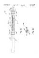
- a conformally positionable ablation catheter 200generally includes an antenna 206 with a proximal end 208 and a distal end 210. Proximal end 208 of antenna 206 is grounded by a shield (not shown) of transmission line 220. It should be appreciated that transmission line 220, which is supported within a distal shaft 222, is typically coupled to a power supply (not shown) which is external to catheter 200. Distal end 210 of antenna 206 is attached to center conductor 224 of transmission line 220.
- antenna 206is in the form of a coil, i.e. an antenna coil, which is made from any suitable material, such as spring steel, beryllium copper, or silver-plated copper.
- the outer diameter of antenna coil 206will vary to some extent based on the particular application of the catheter.
- a catheter suitable for use in an atrial fibrillation applicationmay have typical coil outer diameters in the range of approximately 0.07 to 0.1 inches. More preferably, the outer diameter of antenna coil 206 may be in the range of approximately 0.08 to 0.09 inches.
- a shape memory metal wire 228,is axially located within antenna, or antenna coil, 206.
- shape memory metal wire 228may be positioned such that longitudinal axes of both antenna 206 and shape memory metal wire 228 are aligned.
- Shape memory metal wire 228, which is a flat wire,may be made from any suitable shape memory metal. The shape of shape memory metal 228 is dependent upon the desired positioning attributes of catheter 200.
- a shape memory metalis a moldable metal which has a "default,” or rest, state. This default state may also be considered to be a neutral state.
- a shape memory metalis generally a metal which may be shaped when force is applied to the metal.
- shape memory metalwhen force is removed from a shape memory metal, the metal returns to the default state, which is the original state the metal was in prior to the application of force.
- shape memory metalmay be any suitable "elastic" metal, nickel titanium, copper beryllium alloys, and steel alloys have been observed to work well.
- the typical shape of shape memory metal wire 228is a flat shape, e.g. it has a rectangular cross-section where the height of the rectangle is much greater than the width of the rectangle.
- a flat shapemay be considered to be any shape in which the average height of the shape is significantly greater than the average width of the shape.
- a flat-shaped shape memory metal wire 228is preferred due to the fact that a flat-shaped shape memory metal wire 228 will have the tendency to bend at one axis, or in one plane. Hence, a flat-shaped shape memory metal wire 228 is easier to control, and, therefore, easier to steer since the flat-shaped shape memory metal wire 228 will not exhibit significant bending in more than one plane.
- flat cross-sectional shapesare preferred for shape memory metal wire 228, other shapes such as round wires will also work in many applications.
- sensor conduit 252shown in FIG. 2b (shown in more detail in FIG. 5b), which carries sensor wires 250, shown in FIG. 2b, is generally located along the longitudinal axis of catheter 200.
- sensor conduit 252 which carries sensor wires 250is typically axially located within antenna coil 206.
- the term "axially located”refers to sensor conduit 252 being located such that is parallel to the longitudinal axis of antenna coil 206.
- the sensor wiresare connected with distal electrodes 230 which are provided as part of catheter tip 200 to facilitate positioning of catheter 200 during use.
- Distal electrodes 230are used to detect electro-physiological signals from cardiac tissue and, hence, may be used to map the relevant region of the heart prior to or after an ablation procedure. Distal electrodes 230 may also be used to aid in positioning catheter 200 during the ablation procedure. Distal electrodes 230 may be made from a variety of biocompatible materials, which include stainless steel or iridium platinum. Like distal electrodes 230, proximal electrodes 234, which are typically formed from the same biocompatible materials as distal electrodes 230, may also be used for positioning purposes and to map regions of the heart prior to or after an ablation procedure.
- the distal portion 236 of catheter 200which includes the elongated tube portion 238 of catheter 200, i.e. the section of catheter 200 which encapsulates antenna 206, may be formed from a flexible dielectric material. That is, the material which both fills and surrounds antenna coil 206 is typically a flexible dielectric material. Suitable flexible dielectric materials include, but are not limited to, materials such as silicone.
- GE Liquid Injection Material (LIM) 6040 through 6071a silicone family from General Electric in Waterford, N.Y.
- LIMLiquid Injection Material
- a flexible tubular memberis usually placed or formed over transmission line 220 in a conventional manner.
- the flexible tubular membermay be made from any suitable material including, but not limited to, medical grade polyolefins, fluoropolymers, or polyvinylidene fluoride.
- PEBAX resinsfrom Autochem of Germany have been used with success.
- catheter 200In general, the dimensions of catheter 200 are dependent upon the requirements of a particular application for catheter 200.
- a catheter tip diametere.g. the diameter of elongated tube portion 238, in the range of approximately 7 to 9 French, or approximately 0.092 to 0.141 inches, has been observed to work well for most cardiac applications. It is generally desired that the catheter tip diameter exceed the diameter of the antenna coil, in order to properly encapsulate the antenna coil.
- excess catheter tipin the range of approximately 0.005 to 0.015 inches, as for example approximately 0.01 inches, more than the diameter of the antenna coil work well.
- a catheter tip length, or the length of catheter tip 200 as measured from approximately the proximal end 208 of antenna 206 to the edge 237 of distal portion 236, in the range of approximately 0.2 to 2.5 inchesis preferable. More preferably, a catheter tip length is in the range of approximately 1.2 to 2 inches.
- the catheter tip lengthvaries as a result of any number of factors which include, but are not limited to, the particular requirements of the application and the size of a patient's heart.
- An anchoring tip extension 240is carried by distal portion 236 of catheter 200, and is generally formed from the same material, i.e. a flexible dielectric material, as the elongated tube portion 238 of catheter 200.
- Anchoring tip extension 240may be used to lodge in crevices in the wall of a heart chamber, thereby stabilizing the location of catheter tip 200. In other words, anchoring tip extension 240 may lodge or "hook" in crevices, thereby serving as an anchor to prevent catheter 200 from moving during the course of an ablation procedure.
- Anchoring tip extension 240has axial dimensions which are substantially smaller than the axial dimension, i.e. diameter, of catheter tip 200 which, as previously mentioned, is considered to be the diameter of elongated tube portion 238.
- a length in the range of approximately 0.12 to 0.4 inches, as for example in the range of approximately 0.2 to 0.3 inches,has been shown to be effective for anchoring purposes. Lengths which are much greater than approximately 0.5 inches have the tendency to be difficult to successfully lodge into crevices in the wall of a heart chamber, for example.
- anchoring tip extension 240is generally more flexible than elongated tube portion 238. That is, elongated tube portion 238 is typically stiffer than anchoring tip extension 240.
- the flexibility of anchoring tip extension 240enables anchoring tip extension 240 to be readily lodged into crevices, as for example crevices in the wall of a heart chamber.
- the smaller diameter of anchoring tip extension 240, as compared with the diameter of elongated tube portion 238,results in greater flexibility in anchoring tip extension 240, as compared to elongated tube portion 238, when both are made from the same material.
- anchoring tip extension 240may have substantially the same diameter as elongated tube portion 238, yet anchoring tip extension 240 may be more flexible than elongated tube portion 238. In such embodiments, anchoring tip extension 240 may be created from a different material than elongated tube portion 238.
- edge 237is "flat.” That is, edge 237 is approximately orthogonal to the longitudinal axis of catheter tip 200. However, it should be appreciated that depending upon the nature of the mold and the process used to create anchoring tip extension 240, edge 237 may be curved or angled.
- the cathetermay be fed through the femoral artery or any other suitable vessel and into the appropriate region of the heart.
- the catheter tipwhich is the distal tip of the catheter, is typically fed into the appropriate atrial chamber.
- the conformally positionable ablation catheter as described with respect to FIG. 2ahas an anchoring tip extension which may be lodged in crevices in the atrial chamber. Lodging the anchoring tip extension in crevices serves to anchor the overall catheter tip, thereby reducing the risk of the catheter tip slipping both while the catheter tip is being conformed to the wall of the chamber and during an ablation procedure.
- the conformally positionable ablation catheter as described with respect to FIG. 2amay be passively steered. That is, once the distal portion of the catheter is positioned in proximity of a desired position in a chamber of the heart using standard steering methods, the catheter tip may be rotated such that it may reach the desired position. Specifically, as previously described, a flat shape memory metal wire may bend significantly only along one axis, or in one plane. As such, the catheter may have to be rotated such that the "bending-axis" is properly oriented to facilitate the conforming of the catheter tip to the wall of the heart chamber.
- the anchoring tip extension of the catheter tipengages the wall of the heart chamber or a crevice in the wall, a rotation of the catheter tip and the application of force will generally enable the catheter tip to conform to the wall of the heart chamber, while the anchoring tip extension serves to prevent too much non-conformal movement of the catheter tip. That is, the anchoring tip extension, when lodged in a crevice, may prevent any movement of the catheter tip which is not related to movement of the catheter tip which is meant to cause the catheter tip to conform to the wall of the heart chamber. It should be appreciated that any suitable method may be used to apply force to the catheter tip and, hence, the shape memory metal within the catheter tip.
- One method which may be used to apply force to the catheter tipmay entail applying a force by "pushing” or pressing the distal portion of the catheter tip, and, hence, the anchoring tip extension, further against the wall of the heart chamber.
- the shape memory metalconforms, along with the catheter tip, to the wall of the heart chamber.
- the electrodescan detect electrical signals in the adjacent regions of the heart. If necessary, the catheter may be further inserted, and or withdrawn to facilitate a mapping of the region of interest. Typically, mapping will indicate the location at which relevant electro-physiological signals, or cardiac signals, as for example EKGs, are strongest. This, in turn, will permit a physician to determine the appropriate ablation position.
- the catheteris then positioned as necessary to properly locate the antenna for the ablating procedure. After the antenna is properly positioned, microwave energy is applied to the co-axial transmission line to facilitate the ablation. During the ablation procedure, as well as after the operation is completed, the electrodes may be used to monitor the ablation process as well as the results.
- a suitable microwave generatorwill be described below with reference to FIG. 7.
- the force pressing the catheter against the heart wallmay be at least partially released to enable the catheter to be moved. At least partially releasing the force pressing the catheter against the heart wall also releases at least some of the force on the shape memory metal within the catheter tip. An almost complete removal of force from the catheter tip will enable the shape memory metal and, hence, the catheter tip to return to their original, default shapes. That is, the shape memory metal will return to the state it was in prior to the application of force.
- an antennais attached to the center conductor and the shield of a co-axial cable.
- the co-axial cableis a co-axial transmission line.
- the distal end of the antennais connected with the center conductor, while the proximal end of the antenna is grounded to the shield.
- the antennamay be formed from any suitable material, as for example silver plated copper wire or beryllium copper wire.
- the antennais generally an antenna coil. In the illustrated embodiments, the antenna coil may be helically wound.
- a piece of shape memory metalis insulated with heat shrink tubing in step 308 in order to prevent the shape memory metal from shorting against the antenna.
- the heat shrink tubingis heated and shrunk so that it tightly covers the shape memory metal.
- the shape memory metalmay be any suitable "elastic" metal, as for example nickel titanium, a chromium alloy, or a molybdenum alloy.
- the shape memory metalis typically elongated with a flat, e.g. rectangular, cross-section, it should be appreciated that the shape memory may take on any number of shapes.
- the shape memory metalmay have a round cross-section.
- a shape memory metal with a flat cross-sectionis generally preferred, as such a shape memory metal has the tendency to bend in only one direction, i.e. along a single axis, whereas a shape memory metal with a round cross-section may bend in any number of directions.
- the insulated shape memory metal and a sensor conduitare axially inserted through the antenna coil. That is, the shape memory metal and the sensor conduit are inserted through the antenna coil along the longitudinal axis of the antenna coil.
- the sensor conduitwhich is designed to house sensor leads, may be a polyimide tube.
- the antenna coil, the sensor conduit with the sensor leads, and the shape memory metal, which together comprise an antenna assembly,are placed in a first mold in step 314.
- the first moldis generally used to concentrically position the sensor conduit and shape memory metal relative to the antenna coil and to facilitate the creation of positioning ribs along the perimeter of the antenna coil.
- the first moldwhich will be described in more detail below with reference to FIGS. 4a and 4b, has a cavity 404 which supports the antenna coil 412 and, therefore, enables the antenna coil 412 to be filled with a dielectric material.
- the cavity 404has a diameter which is substantially equal to the diameter of the antenna coil 412, and is therefore able to support the antenna coil 412 while it is within the cavity 404.
- the antenna assembly 410is positioned in the first mold 400 such that the sensor leads 414 extend through the first mold 400.
- a first injection molding operationis performed to fill the center of the antenna coil 412 and to create positioning ribs and an extension plug around the antenna coil 412. That is, a first injection molding operation is essentially used to partially encapsulate the antenna assembly 410.
- the partially encapsulated antenna assembly 410will be described below with respect to FIGS. 5a and 5b.
- the positioning ribs 510are formed along the perimeter of the antenna assembly such that the distance from the edge of one positioning rib, as for example edge 512a or positioning rib 510a, to the edge of a directly opposing positioning rib, as for example edge 512c of positioning rib 510c, is equal to the desired, final outer diameter of the completed antenna assembly.
- the first injection molding operationmay be performed using any suitable pliant material including, but not limited to, silicone.
- siliconeIn addition to being flexible when it is cured, silicone is not self-heating, which is a desirable characteristic for a material used in the fabrication of a catheter.
- One type of silicone which has been observed to work well, as mentioned above,is GE Liquid Injection Material (LIM) 6040, a silicone from General Electric in Waterford, N.Y.
- a distal electrode 538is generally a band.
- the distal electrodes 538are annular bands which may be cut into segments after they are mounted, i.e. installed, or the distal electrodes 538 independent segments that form associated bands only after installation.
- the distal electrodes 538are connected to the specific sensor, or electrode, leads 537 with which they are associated, thereby forming an electrode ring assembly having the desired number of electrode wires, such as a pair of electrode wires, which may then be slid over the antenna assembly and positioned in its desired location.
- heat shrink tubingis then heated and shrunk over the distal electrodes 538 such that the heat shrink tubing tightly covers the electrodes 538 and seals electrode wire holes through which the sensor wires 537 pass.
- the distal electrodes 538may be covered with ultraviolet (UV) curable epoxy which is then cured to set the electrodes 538.
- UVultraviolet
- the electrodes 538are provided to facilitate positioning of the catheter 502 during use.
- the electrodes 538are used to detect electro-physiological signals from cardiac tissue and may therefore be used to map the relevant region of the heart prior to or after an ablation procedure.
- the electrodes 538may also be used to aid in positioning the catheter 502 for use and to monitor the patient's condition during the ablation process.
- electrodes 538may be made from a variety of different biocompatible materials, electrodes 538 are typically made of either stainless steel or iridium platinum.
- step 320the antenna assembly, which, at this point in the process, is partially molded over, is placed in a second mold which is used both to set the final outer diameter of the tip, i.e. the general catheter tip, of the completed antenna assembly, as well as to create an anchoring tip extension at the distal end of the catheter tip.
- the distance from the edge of one positioning rib 510 to the edge of a directly opposing positioning rib 510is approximately equal to final outer diameter of the completed antenna assembly.
- the second moldbesides being used to set the final outer diameter of the completed antenna assembly and to create the anchoring tip extension, is used to eliminate any bubbles which may have been formed in the catheter as a result of the first injection molding process. The second mold will be discussed in more detail below with reference to FIG. 6.
- a second injection molding operationis performed in step 322 to create the final desired diameter of the antenna assembly, or more specifically, the final desired tip diameter of the antenna assembly using the second mold.
- the second injection molding operationalso serves to create an anchoring, or positioning, tip extension at the distal end of the antenna assembly and to eliminate bubbles in the catheter.
- the anchoring tip extensionis formed at the distal end of the extension plug.
- the same material which was used in the first injection molding operationis generally also used for the second injection molding operation, though any suitable material may be used.
- the antenna assembly with the final desired tip diameter and an anchoring tip extensionmay be considered to be a conformal positioning assembly with an anchoring tip.
- the remaining steps associated with the catheter construction processare performed in step 324. These steps include, but are not limited to, inserting the co-axial cable into a distal shaft, or a flexible tubular member, in a conventional manner.
- the conventional mannerinvolves binding the antenna assembly to the distal end of the flexible tubular member and attaching a handle to the proximal end of the flexible member.
- the flexible tubular membermay be made from any suitable material including, but not limited to, medical grade polyolefins, fluoropolymers, or polyvinylidene fluoride.
- PEBAX resinsfrom Autochem of Germany have been used with success in molding the body of the catheter.
- Stiffening wires, steering wires, additional sensor wires, etc.may all be included in the final assembly as required by a particular design.
- FIG. 4ais a diagrammatic cross-sectional view of a mold used to position an antenna assembly, i.e. an antenna, a shape memory wire, and a sensor conduit which houses sensor wires.
- FIG. 4bis a diagrammatic top view of the mold shown in FIG. 4a.
- Mold 400which may be made from any suitable material, has a main cavity 404 in which an antenna assembly 410 is situated.
- Main cavity 404comes into contact with rib cavities 424 which are used to form positioning ribs around antenna assembly 410.
- Main cavity 404is further sized such that edges of main cavity, as for example edges 411, come into contact with antenna assembly 410 and, more specifically, an antenna coil 412. That is, the diameter of main cavity 404 is substantially the same as the diameter of antenna coil 412.
- the shape, or an axial cross-section, of main cavity 404is dependent upon the desired shape, i.e. axial cross-section, of the molded over antenna assembly (not shown).
- the shape of main cavity 404is either circular (as shown) or oval. However, it should be understood that the shape may be widely varied depending upon the requirements of a particular antenna assembly.
- antenna assembly 410also includes a shape memory wire (not shown) and a transmission line 415.
- antenna assembly 410has been generically represented, and the shape memory wire has not been shown in FIG. 4a.
- Sensor wires 414which are attached to an electrode ring 416, extend past the top edge 420 of mold 400.
- antenna assembly 410In order to align the components of antenna assembly 410, i.e. antenna coil 412, sensor conduit 413 with sensor wires 414, the shape memory metal (not shown), the transmission line 415, as required for a particular catheter, mechanisms external to mold 400 may be used to hold and otherwise position antenna assembly 410.
- mold 400is capable of supporting antenna coil 412 for positioning purposes.
- the shape memory metal and the sensor conduitmay suitably be aligned by allowing the shape memory metal and sensor conduit 413 to be held against transmission line 415 within antenna assembly 410.
- mold 400is implemented to fill the center of antenna coil 412 as well as to create positioning ribs and an extension plug around antenna assembly 410.
- the positioning ribsare formed using rib cavities 424, while the extension plug is generally formed on antenna assembly 410 near top edge 420 of mold 400 in the top portion 430 of main cavity 404.
- the extension plugis formed to provide a surface over which electrode ring 416 may be mounted.
- the diameter of the extension plug after the first molding operationwill generally be the equal to the diameter of main cavity 404.
- mold 400may be comprised of at least two distinct pieces which may be interconnected during the molding process, and separated after the molding process in order to remove antenna assembly 410 from mold 400.
- main cavity 404extends approximately the length of mold 400, while rib cavities 424 extend less than the length of mold 400.
- the relative depths, or more generally, dimensions of main cavity 400 and rib cavities 424may vary greatly depending upon the requirements of a specific antenna assembly.
- FIG. 5aa diagrammatic cross-sectional axial view of a partially molded conformally positionable antenna assembly after a first molding process in accordance with an embodiment of the present invention will be described.
- the cross-sectional viewis shown without an antenna coil, a sensor conduit, a shape memory wire and transmission line for illustrative purposes. That is, only the "outline" of conformally positionable antenna assembly 502 is shown for ease of illustration. Further, the cross-section of antenna assembly 502 that is shown is away from the extension plug formed at the distal end of antenna assembly 502.
- the "main body” 506 of antenna assemblywhich is comprised of any suitable malleable material, as for example silicone as described above, encapsulates the antenna coil, sensor conduit, shape memory wire, etc. Although main body 506 may have any cross-sectional shape, in the embodiment as shown, main body 506 has a circular cross-section. Positioning ribs 510, which are used to position antenna assembly 502 within a second mold used to complete the antenna tip assembly as will be described below with reference to FIG. 6, are formed along the perimeter of main body 506, and are made of the same material as main body 506.
- the tip-to-tip distance D from the tip of a first positioning rib, as for example positioning rib 510a with tip 512a, to the tip of a second positioning rib which is directly opposite the first positioning rib, as for example positioning rib 510c with tip 512c,is generally approximately equal to the desired diameter of the completed antenna tip (not shown).
- Positioning ribs 510may take on any suitable cross-section. However, positioning ribs 510 which have curved, e.g. semi-circular, axial cross-sections are preferable due to the fact that the final antenna tip assembly has a round cross-section. That is, the completed catheter assembly has a round cross-section. Hence, positioning ribs 510 have curved cross-sections for ease of manufacturability. As will be appreciated by those skilled in the art, utilizing positioning ribs 510 with axial cross-sections which are rectangular, for example, would have the tendency to require an end mill to "shave" the edges of the rectangle in order to achieve the desired diameter of the completed antenna tip.
- positioning tips 510may be used, in the described embodiment, four positioning ribs 510 which are symmetrical about the perimeter of main body 510 are shown. This number and orientation of positioning ribs 510 have been shown to be effective in securely positioning antenna assembly 502 within the aforementioned second mold.
- Each positioning ribas for example positioning rib 510a, has a "height," i.e. tip-to-base dimension, d in the range of approximately 0.005 to 0.01 inches, as for example approximately 0.007 inches.
- FIG. 5ba diagrammatic longitudinal side view of the partially molded conformally positionable antenna assembly of FIG. 5a.
- Antenna assembly 502includes main body 506, an extension plug 520 formed at the distal end of antenna assembly 502, and positioning ribs 512. It should be appreciated that only two positioning ribs, i.e. positioning ribs 510a and 510c, have been shown for ease of illustration.
- Antenna assembly 530includes, as previously described, an antenna coil 530, a sensor conduit 536, and a shape memory metal 542. Antenna coil 530 is coupled at a proximal end to the shield 532 of coaxial cable, or transmission line, 533 which effectively serves to ground antenna coil 530.
- antenna coil 530is coupled to the center conductor 534 of coaxial cable 533.
- Sensor conduit 536houses sensor wires 537 which are coupled to an electrode 538. Electrode 538, as shown, has not yet been mounted over extension plug 520. Although only one electrode 538 has been shown, it should be appreciated that the number of electrodes coupled to sensor wires 537, as well as the number of sensor wires 537, is dependent upon the requirements of a particular catheter.
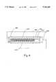
- FIG. 6is a diagrammatic top view of the mold used to create a desired tip diameter and an anchoring tip extension for a catheter in accordance with an embodiment of the present invention.
- Mold 602is used primarily to create the desired tip diameter for a conformally positionable catheter. Mold 602 is also used to eliminate any bubbles which may have formed in the dielectric material used in the first molding process described above with respect to FIGS. 4a and 4b. Mold 602 includes a main cavity 606 which holds the antenna assembly 610, as previously described with respect to FIGS. 5a and 5b, after the distal electrode of the antenna assembly has been properly mounted over the extension plug.
- Antenna assembly 610will fit into main cavity 606, prior to the second injection molding process, substantially as shown. As the tip-to-tip distance between positioning ribs 616 is approximately equal to the final diameter of the catheter tip formed using mold 602, positioning ribs 616 is shown to be flush with the edges 620 of main cavity 606. The shape of main cavity 606 reflects the desired body shape of the completed antenna assembly.
- Anchoring tip extension cavity 620extends from main cavity 606 as shown.
- Anchoring tip extension cavity 620is sized for the anchoring tip extension to be formed at the distal end of the completed catheter tip. That is, the shape of anchoring tip extension cavity 620, as well as the dimensions of anchoring tip extension cavity 620, are the desired shape and dimensions of the anchoring tip extension as shown in FIG. 2a.
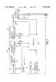
- FIG. 7is a diagrammatic illustration of a microwave ablation catheter system in accordance with an embodiment of the present invention.
- An ablation catheter system 10generally includes a power supply 20 which is designed to generate controlled electromagnetic energy, a catheter 50 which is designed for insertion into a vessel (such as a coronary vessel) in the body of a patient and a connector 71 for coupling the power supply 20 to the catheter 50.
- the cathetertypically includes a flexible outer tubing, a co-axial microwave transmission line that extends through the flexible tubing, and an antenna 56 coupled to the distal end of the co-axial transmission line.
- the connectorcouples transmission line 53 to external power supply 20.
- a handle 73may be provided for use by the surgeon to facilitate steering and potentially other control functions.
- catheter 50may include a variety of sensors for monitoring the patient during insertion, positioning and/or use of the catheter 50.
- sensorsmay include a plurality of mapping electrodes 230, as shown in FIG. 2a, and one or more thermocouple wires (not shown).
- the co-axial microwave transmission line 53includes a center conductor, a shield, and a dielectric material disposed between the center conductor and shield.
- the anchoring tip extensionmay be used to facilitate the positioning and stability of catheters which are not conformally positionable. That is, the anchoring tip extension may be used to anchor a catheter which does not include a shape memory metal. Further, the anchoring tip extension may serve to anchor conventional catheters, ablation or otherwise, without departing from the spirit or scope of the present invention.
- anchoring tip extensionhas been described as being formed by the second molding operation, it should be appreciated that anchoring tip extension may instead be formed during the first molding operation. Also, a combination of the previously described first and second molding operations may be used to form the anchoring tip extension such that the anchoring tip extension is partially formed in the first molding operation, and completed in the second molding operation.
- a single molding operationmay be used both to align the antenna assembly, to create the desired tip diameter of the ablation catheter tip, and to form the anchoring tip extension.
- three molding operationsmay be used to create a conformally positionable microwave ablation catheter with an anchoring tip extension.
- the anchoring tip extensionmay be formed using a molding process intended only to form the anchoring tip extension. Therefore, the present examples are to be considered as illustrative and not restrictive, and the invention is not to be limited to the details given herein, but may be modified within the scope of the appended claims.
Landscapes
- Health & Medical Sciences (AREA)
- Life Sciences & Earth Sciences (AREA)
- Surgery (AREA)
- Engineering & Computer Science (AREA)
- Veterinary Medicine (AREA)
- Public Health (AREA)
- Nuclear Medicine, Radiotherapy & Molecular Imaging (AREA)
- General Health & Medical Sciences (AREA)
- Biomedical Technology (AREA)
- Animal Behavior & Ethology (AREA)
- Medical Informatics (AREA)
- Molecular Biology (AREA)
- Heart & Thoracic Surgery (AREA)
- Otolaryngology (AREA)
- Physics & Mathematics (AREA)
- Electromagnetism (AREA)
- Cardiology (AREA)
- Plasma & Fusion (AREA)
- Radiology & Medical Imaging (AREA)
- Surgical Instruments (AREA)
Abstract
Description
Claims (21)
Priority Applications (2)
| Application Number | Priority Date | Filing Date | Title |
|---|---|---|---|
| US08/732,045US5810803A (en) | 1996-10-16 | 1996-10-16 | Conformal positioning assembly for microwave ablation catheter |
| US08/755,998US5741249A (en) | 1996-10-16 | 1996-11-25 | Anchoring tip assembly for microwave ablation catheter |
Applications Claiming Priority (2)
| Application Number | Priority Date | Filing Date | Title |
|---|---|---|---|
| US08/732,045US5810803A (en) | 1996-10-16 | 1996-10-16 | Conformal positioning assembly for microwave ablation catheter |
| US08/755,998US5741249A (en) | 1996-10-16 | 1996-11-25 | Anchoring tip assembly for microwave ablation catheter |
Publications (1)
| Publication Number | Publication Date |
|---|---|
| US5741249Atrue US5741249A (en) | 1998-04-21 |
Family
ID=38626948
Family Applications (1)
| Application Number | Title | Priority Date | Filing Date |
|---|---|---|---|
| US08/755,998Expired - LifetimeUS5741249A (en) | 1996-10-16 | 1996-11-25 | Anchoring tip assembly for microwave ablation catheter |
Country Status (1)
| Country | Link |
|---|---|
| US (1) | US5741249A (en) |
Cited By (250)
| Publication number | Priority date | Publication date | Assignee | Title |
|---|---|---|---|---|
| US5954665A (en)* | 1995-06-07 | 1999-09-21 | Biosense, Inc. | Cardiac ablation catheter using correlation measure |
| US5971983A (en)* | 1997-05-09 | 1999-10-26 | The Regents Of The University Of California | Tissue ablation device and method of use |
| US6016811A (en)* | 1998-09-01 | 2000-01-25 | Fidus Medical Technology Corporation | Method of using a microwave ablation catheter with a loop configuration |
| US6024740A (en) | 1997-07-08 | 2000-02-15 | The Regents Of The University Of California | Circumferential ablation device assembly |
| US6078830A (en)* | 1997-10-01 | 2000-06-20 | Ep Technologies, Inc. | Molded catheter distal end assembly and process for the manufacture thereof |
| WO2000035363A1 (en) | 1998-12-14 | 2000-06-22 | Ormsby Theodore C | Radio-frequency based catheter system and hollow co-axial cable for ablation of body tissues |
| GB2347084A (en)* | 1999-02-26 | 2000-08-30 | Medtronic Inc | Ablation lead with screw tip |
| US6156031A (en)* | 1995-08-09 | 2000-12-05 | Eclipse Surgical Technologies | Transmyocardial revascularization using radiofrequency energy |
| US6164283A (en) | 1997-07-08 | 2000-12-26 | The Regents Of The University Of California | Device and method for forming a circumferential conduction block in a pulmonary vein |
| US6245064B1 (en) | 1997-07-08 | 2001-06-12 | Atrionix, Inc. | Circumferential ablation device assembly |
| US6258118B1 (en) | 1998-11-25 | 2001-07-10 | Israel Aircraft Industries Ltd. | Removable support device |
| EP1118310A1 (en)* | 2000-01-18 | 2001-07-25 | AFX, Inc. | A microwave ablation instrument with flexible antenna assembly and method |
| US6267757B1 (en) | 1995-08-09 | 2001-07-31 | Eclipse Surgical Technologies, Inc. | Revascularization with RF ablation |
| US6402746B1 (en) | 1996-12-19 | 2002-06-11 | Ep Technologies, Inc. | Branched structures for supporting multiple electrode elements |
| US6413273B1 (en) | 1998-11-25 | 2002-07-02 | Israel Aircraft Industries Ltd. | Method and system for temporarily supporting a tubular organ |
| US6458123B1 (en)* | 2000-04-27 | 2002-10-01 | Biosense Webster, Inc. | Ablation catheter with positional sensor |
| US6464693B1 (en) | 2000-03-06 | 2002-10-15 | Plc Medical Systems, Inc. | Myocardial revascularization |
| US6468272B1 (en)* | 1997-10-10 | 2002-10-22 | Scimed Life Systems, Inc. | Surgical probe for supporting diagnostic and therapeutic elements in contact with tissue in or around body orifices |
| US20020193786A1 (en)* | 1998-10-23 | 2002-12-19 | Dany Berube | Directional microwave ablation instrument with off-set energy delivery portion |
| US6500174B1 (en) | 1997-07-08 | 2002-12-31 | Atrionix, Inc. | Circumferential ablation device assembly and methods of use and manufacture providing an ablative circumferential band along an expandable member |
| US6502576B1 (en) | 1997-07-08 | 2003-01-07 | The Regents Of The University Of California | Device and method for forming a circumferential conduction block in a pulmonary vein |
| US6514249B1 (en) | 1997-07-08 | 2003-02-04 | Atrionix, Inc. | Positioning system and method for orienting an ablation element within a pulmonary vein ostium |
| US6527769B2 (en) | 1998-03-02 | 2003-03-04 | Atrionix, Inc. | Tissue ablation system and method for forming long linear lesion |
| US20030060822A1 (en)* | 1998-05-06 | 2003-03-27 | Schaer Alan K. | Irrigated ablation device assembly |
| US20030060820A1 (en)* | 1997-07-08 | 2003-03-27 | Maguire Mark A. | Tissue ablation device assembly and method for electrically isolating a pulmonary vein ostium from an atrial wall |
| US6542781B1 (en) | 1999-11-22 | 2003-04-01 | Scimed Life Systems, Inc. | Loop structures for supporting diagnostic and therapeutic elements in contact with body tissue |
| US20030083654A1 (en)* | 2000-12-29 | 2003-05-01 | Afx, Inc. | Tissue ablation system with a sliding ablating device and method |
| US20030125725A1 (en)* | 2002-01-03 | 2003-07-03 | Afx Inc. | Catheter having improved steering |
| US6595989B1 (en) | 1999-05-11 | 2003-07-22 | Atrionix, Inc. | Balloon anchor wire |
| US6599288B2 (en) | 2000-05-16 | 2003-07-29 | Atrionix, Inc. | Apparatus and method incorporating an ultrasound transducer onto a delivery member |
| US6607502B1 (en) | 1998-11-25 | 2003-08-19 | Atrionix, Inc. | Apparatus and method incorporating an ultrasound transducer onto a delivery member |
| US20030163128A1 (en)* | 2000-12-29 | 2003-08-28 | Afx, Inc. | Tissue ablation system with a sliding ablating device and method |
| US20030216721A1 (en)* | 2002-01-15 | 2003-11-20 | The Regents Of The University Of Calfornia | System and method providing directional ultrasound therapy to skeletal joints |
| US6652515B1 (en) | 1997-07-08 | 2003-11-25 | Atrionix, Inc. | Tissue ablation device assembly and method for electrically isolating a pulmonary vein ostium from an atrial wall |
| US20030225331A1 (en)* | 2002-01-23 | 2003-12-04 | The Regents Of The University Of California | Implantable thermal treatment method and apparatus |
| US20040055572A1 (en)* | 2002-09-24 | 2004-03-25 | Caterpillar Inc. | Hydraulic pump circuit |
| US20040106937A1 (en)* | 2002-06-21 | 2004-06-03 | Afx, Inc. | Clamp accessory and method for an ablation instrument |
| US6752805B2 (en) | 2000-06-13 | 2004-06-22 | Atrionix, Inc. | Surgical ablation probe for forming a circumferential lesion |
| US6758830B1 (en) | 1999-05-11 | 2004-07-06 | Atrionix, Inc. | Catheter positioning system |
| US6869431B2 (en) | 1997-07-08 | 2005-03-22 | Atrionix, Inc. | Medical device with sensor cooperating with expandable member |
| US20050090880A1 (en)* | 2002-03-20 | 2005-04-28 | Fogazzi Di Venturelli Andrea &C. S.N.C. | Catheter with flexible cooled electrode |
| US20050159738A1 (en)* | 2004-01-21 | 2005-07-21 | Naheed Visram | Surgical perforation device with electrocardiogram (ECG) monitoring ability and method of using ECG to position a surgical perforation device |
| US20050192654A1 (en)* | 2004-01-30 | 2005-09-01 | Nmt Medical, Inc. | Welding systems useful for closure of cardiac openings |
| US6966908B2 (en) | 1997-07-08 | 2005-11-22 | Atrionix, Inc. | Tissue ablation device assembly and method for electrically isolating a pulmonary vein ostium from an atrial wall |
| US6976986B2 (en) | 2000-04-12 | 2005-12-20 | Afx, Inc. | Electrode arrangement for use in a medical instrument |
| US20060063121A1 (en)* | 2004-09-22 | 2006-03-23 | Barry David L | Containment apparatus for multi-pass ovens |
| US7029471B2 (en) | 1996-12-19 | 2006-04-18 | Ep Technologies, Inc. | Loop structures for supporting multiple electrode elements |
| US20060142752A1 (en)* | 2001-11-29 | 2006-06-29 | Ormsby Theodore C | Radio-frequency-based catheter system with improved deflection and steering mechanisms |
| US20060142756A1 (en)* | 2003-01-21 | 2006-06-29 | Baylis Medical Company Inc. | Method of surgical perforation via the delivery of energy |
| US20060147245A1 (en)* | 2004-12-30 | 2006-07-06 | Carl Cetera | Implement grip |
| US20060217694A1 (en)* | 2000-12-29 | 2006-09-28 | Afx, Inc. | Method of positioning a medical instrument |
| US20060276781A1 (en)* | 2004-04-29 | 2006-12-07 | Van Der Weide Daniel W | Cannula cooling and positioning device |
| US20060282069A1 (en)* | 2001-11-02 | 2006-12-14 | Mani Prakash | High-strength microwave antenna assemblies and methods of use |
| US20070016180A1 (en)* | 2004-04-29 | 2007-01-18 | Lee Fred T Jr | Microwave surgical device |
| US20070021746A1 (en)* | 2004-06-07 | 2007-01-25 | Boston Scientific Scimend, Inc. (Formerly Known As Scimed Life Systems, Inc.) | Ablation catheters having slidable anchoring capability and methods of using same |
| US20070055229A1 (en)* | 2005-09-06 | 2007-03-08 | Kladakis Stephanie M | In tunnel electrode for sealing intracardiac defects |
| US20070055333A1 (en)* | 2005-09-06 | 2007-03-08 | Sean Forde | Removable intracardiac RF device |
| US7192427B2 (en) | 2002-02-19 | 2007-03-20 | Afx, Inc. | Apparatus and method for assessing transmurality of a tissue ablation |
| US20070066972A1 (en)* | 2001-11-29 | 2007-03-22 | Medwaves, Inc. | Ablation catheter apparatus with one or more electrodes |
| US20070066864A1 (en)* | 2005-09-06 | 2007-03-22 | Sean Forde | Devices and methods for treating cardiac tissue |
| US20070106290A1 (en)* | 2005-11-08 | 2007-05-10 | Turano Thomas A | Conformable electrode catheter and method of use |
| US7226446B1 (en) | 1999-05-04 | 2007-06-05 | Dinesh Mody | Surgical microwave ablation assembly |
| US20070288079A1 (en)* | 2006-03-24 | 2007-12-13 | Micrablate | Energy delivery system and uses thereof |
| US7346399B2 (en) | 1999-05-28 | 2008-03-18 | Afx, Inc. | Monopole tip for ablation catheter |
| US20080119921A1 (en)* | 2004-04-29 | 2008-05-22 | Micrablate | Air-core microwave ablation antennas |
| US20080135217A1 (en)* | 2003-07-18 | 2008-06-12 | Roman Turovskiy | Devices and Methods for Cooling Microwave Antennas |
| US20080147056A1 (en)* | 2006-07-14 | 2008-06-19 | Micrablate | Energy delivery systems and uses thereof |
| US20080161890A1 (en)* | 2007-01-03 | 2008-07-03 | Boston Scientific Scimed, Inc. | Methods, systems, and apparatuses for protecting esophageal tissue during ablation |
| US20080294162A1 (en)* | 2007-05-22 | 2008-11-27 | Francesca Rossetto | Energy delivery conduits for use with electrosugical devices |
| US7467015B2 (en) | 2004-04-29 | 2008-12-16 | Neuwave Medical, Inc. | Segmented catheter for tissue ablation |
| US20090005766A1 (en)* | 2007-06-28 | 2009-01-01 | Joseph Brannan | Broadband microwave applicator |
| US20090082762A1 (en)* | 2007-09-20 | 2009-03-26 | Ormsby Theodore C | Radio frequency energy transmission device for the ablation of biological tissues |
| US20090299360A1 (en)* | 2008-05-28 | 2009-12-03 | Medwaves, Inc. | Tissue ablation apparatus and method using ultrasonic imaging |
| US20100004650A1 (en)* | 2008-07-01 | 2010-01-07 | Medwaves, Inc. | Angioplasty and tissue ablation apparatus and method |
| CN1832708B (en)* | 2003-08-08 | 2010-04-14 | 麦迪威公司 | Radio-frequency based catheter system |
| US20100121319A1 (en)* | 2008-11-10 | 2010-05-13 | Microcube, Llc | Methods and devices for applying energy to bodily tissues |
| US20100125269A1 (en)* | 2008-10-21 | 2010-05-20 | Microcube, Limited Liability Corporation | Microwave treatment devices and methods |
| US20100137857A1 (en)* | 2008-10-21 | 2010-06-03 | Microcube, Limited Liability Corporation | Methods and devices for applying energy to bodily tissues |
| US7799019B2 (en) | 2005-05-10 | 2010-09-21 | Vivant Medical, Inc. | Reinforced high strength microwave antenna |
| US20100249888A1 (en)* | 2008-07-06 | 2010-09-30 | Glenn Richard A | Intravascular implant anchors having remote communication and/or battery recharging capabilities |
| US20110004205A1 (en)* | 2008-10-21 | 2011-01-06 | Chu Chun Yiu | Methods and devices for delivering microwave energy |
| WO2011017168A2 (en) | 2009-07-28 | 2011-02-10 | Neuwave Medical, Inc. | Energy delivery systems and uses thereof |
| US20110130750A1 (en)* | 2009-11-30 | 2011-06-02 | Medwaves, Inc. | Radio frequency ablation system with tracking sensor |
| US20110196298A1 (en)* | 2008-10-31 | 2011-08-11 | Cathrx Ltd | Catheter Assembly |
| US7998139B2 (en) | 2007-04-25 | 2011-08-16 | Vivant Medical, Inc. | Cooled helical antenna for microwave ablation |
| US20110224666A1 (en)* | 2003-01-21 | 2011-09-15 | Gareth Davies | Method of surgical perforation via the delivery of energy |
| WO2011130104A1 (en)* | 2010-04-12 | 2011-10-20 | Enteroptyx, Inc. | Induction heater system for shape memory medical implants and methods of activating shape memory medical implants within the mammalian body |
| CN102688094A (en)* | 2012-06-06 | 2012-09-26 | 王建新 | Cold tip temperature control fissure microwave ablation radiator |
| US8651146B2 (en) | 2007-09-28 | 2014-02-18 | Covidien Lp | Cable stand-off |
| US8672932B2 (en) | 2006-03-24 | 2014-03-18 | Neuwave Medical, Inc. | Center fed dipole for use with tissue ablation systems, devices and methods |
| US8880185B2 (en) | 2010-06-11 | 2014-11-04 | Boston Scientific Scimed, Inc. | Renal denervation and stimulation employing wireless vascular energy transfer arrangement |
| US8932208B2 (en) | 2005-05-26 | 2015-01-13 | Maquet Cardiovascular Llc | Apparatus and methods for performing minimally-invasive surgical procedures |
| US8939970B2 (en) | 2004-09-10 | 2015-01-27 | Vessix Vascular, Inc. | Tuned RF energy and electrical tissue characterization for selective treatment of target tissues |
| US8951251B2 (en) | 2011-11-08 | 2015-02-10 | Boston Scientific Scimed, Inc. | Ostial renal nerve ablation |
| US8974451B2 (en) | 2010-10-25 | 2015-03-10 | Boston Scientific Scimed, Inc. | Renal nerve ablation using conductive fluid jet and RF energy |
| US9023034B2 (en) | 2010-11-22 | 2015-05-05 | Boston Scientific Scimed, Inc. | Renal ablation electrode with force-activatable conduction apparatus |
| US9023024B2 (en) | 2007-06-20 | 2015-05-05 | Covidien Lp | Reflective power monitoring for microwave applications |
| US9028472B2 (en) | 2011-12-23 | 2015-05-12 | Vessix Vascular, Inc. | Methods and apparatuses for remodeling tissue of or adjacent to a body passage |
| US9028485B2 (en) | 2010-11-15 | 2015-05-12 | Boston Scientific Scimed, Inc. | Self-expanding cooling electrode for renal nerve ablation |
| US9044254B2 (en) | 2012-08-07 | 2015-06-02 | Covidien Lp | Microwave ablation catheter and method of utilizing the same |
| US9050106B2 (en) | 2011-12-29 | 2015-06-09 | Boston Scientific Scimed, Inc. | Off-wall electrode device and methods for nerve modulation |
| US9060761B2 (en) | 2010-11-18 | 2015-06-23 | Boston Scientific Scime, Inc. | Catheter-focused magnetic field induced renal nerve ablation |
| US9079000B2 (en) | 2011-10-18 | 2015-07-14 | Boston Scientific Scimed, Inc. | Integrated crossing balloon catheter |
| US9084609B2 (en) | 2010-07-30 | 2015-07-21 | Boston Scientific Scime, Inc. | Spiral balloon catheter for renal nerve ablation |
| US9089350B2 (en) | 2010-11-16 | 2015-07-28 | Boston Scientific Scimed, Inc. | Renal denervation catheter with RF electrode and integral contrast dye injection arrangement |
| US9119632B2 (en) | 2011-11-21 | 2015-09-01 | Boston Scientific Scimed, Inc. | Deflectable renal nerve ablation catheter |
| US9121774B2 (en) | 2012-06-22 | 2015-09-01 | Covidien Lp | Microwave thermometry for microwave ablation systems |
| US9119600B2 (en) | 2011-11-15 | 2015-09-01 | Boston Scientific Scimed, Inc. | Device and methods for renal nerve modulation monitoring |
| US9125667B2 (en) | 2004-09-10 | 2015-09-08 | Vessix Vascular, Inc. | System for inducing desirable temperature effects on body tissue |
| US9125666B2 (en) | 2003-09-12 | 2015-09-08 | Vessix Vascular, Inc. | Selectable eccentric remodeling and/or ablation of atherosclerotic material |
| US9155589B2 (en) | 2010-07-30 | 2015-10-13 | Boston Scientific Scimed, Inc. | Sequential activation RF electrode set for renal nerve ablation |
| US9162046B2 (en) | 2011-10-18 | 2015-10-20 | Boston Scientific Scimed, Inc. | Deflectable medical devices |
| US9173696B2 (en) | 2012-09-17 | 2015-11-03 | Boston Scientific Scimed, Inc. | Self-positioning electrode system and method for renal nerve modulation |
| US9186210B2 (en) | 2011-10-10 | 2015-11-17 | Boston Scientific Scimed, Inc. | Medical devices including ablation electrodes |
| US9186209B2 (en) | 2011-07-22 | 2015-11-17 | Boston Scientific Scimed, Inc. | Nerve modulation system having helical guide |
| US9192435B2 (en) | 2010-11-22 | 2015-11-24 | Boston Scientific Scimed, Inc. | Renal denervation catheter with cooled RF electrode |
| US9192438B2 (en) | 2011-12-21 | 2015-11-24 | Neuwave Medical, Inc. | Energy delivery systems and uses thereof |
| US9192790B2 (en) | 2010-04-14 | 2015-11-24 | Boston Scientific Scimed, Inc. | Focused ultrasonic renal denervation |
| US9216055B2 (en) | 2009-08-05 | 2015-12-22 | Scr Inc. | Systems, devices and methods for treating the heart with ablation |
| US9220558B2 (en) | 2010-10-27 | 2015-12-29 | Boston Scientific Scimed, Inc. | RF renal denervation catheter with multiple independent electrodes |
| US9220561B2 (en) | 2011-01-19 | 2015-12-29 | Boston Scientific Scimed, Inc. | Guide-compatible large-electrode catheter for renal nerve ablation with reduced arterial injury |
| US9265969B2 (en) | 2011-12-21 | 2016-02-23 | Cardiac Pacemakers, Inc. | Methods for modulating cell function |
| US9277955B2 (en) | 2010-04-09 | 2016-03-08 | Vessix Vascular, Inc. | Power generating and control apparatus for the treatment of tissue |
| US9297845B2 (en) | 2013-03-15 | 2016-03-29 | Boston Scientific Scimed, Inc. | Medical devices and methods for treatment of hypertension that utilize impedance compensation |
| US9326751B2 (en) | 2010-11-17 | 2016-05-03 | Boston Scientific Scimed, Inc. | Catheter guidance of external energy for renal denervation |
| US9327100B2 (en) | 2008-11-14 | 2016-05-03 | Vessix Vascular, Inc. | Selective drug delivery in a lumen |
| US9358365B2 (en) | 2010-07-30 | 2016-06-07 | Boston Scientific Scimed, Inc. | Precision electrode movement control for renal nerve ablation |
| US9364284B2 (en) | 2011-10-12 | 2016-06-14 | Boston Scientific Scimed, Inc. | Method of making an off-wall spacer cage |
| US9408661B2 (en) | 2010-07-30 | 2016-08-09 | Patrick A. Haverkost | RF electrodes on multiple flexible wires for renal nerve ablation |
| US9420955B2 (en) | 2011-10-11 | 2016-08-23 | Boston Scientific Scimed, Inc. | Intravascular temperature monitoring system and method |
| US9433760B2 (en) | 2011-12-28 | 2016-09-06 | Boston Scientific Scimed, Inc. | Device and methods for nerve modulation using a novel ablation catheter with polymeric ablative elements |
| US9463062B2 (en) | 2010-07-30 | 2016-10-11 | Boston Scientific Scimed, Inc. | Cooled conductive balloon RF catheter for renal nerve ablation |
| US9486355B2 (en) | 2005-05-03 | 2016-11-08 | Vessix Vascular, Inc. | Selective accumulation of energy with or without knowledge of tissue topography |
| US9549779B2 (en) | 2001-11-02 | 2017-01-24 | Covidien Lp | High-strength microwave antenna assemblies |
| US9579030B2 (en) | 2011-07-20 | 2017-02-28 | Boston Scientific Scimed, Inc. | Percutaneous devices and methods to visualize, target and ablate nerves |
| US9610122B2 (en) | 2013-03-29 | 2017-04-04 | Covidien Lp | Step-down coaxial microwave ablation applicators and methods for manufacturing same |
| USRE46362E1 (en) | 2009-11-16 | 2017-04-11 | Covidien Lp | Twin sealing chamber hub |
| US9649156B2 (en) | 2010-12-15 | 2017-05-16 | Boston Scientific Scimed, Inc. | Bipolar off-wall electrode device for renal nerve ablation |
| US9668811B2 (en) | 2010-11-16 | 2017-06-06 | Boston Scientific Scimed, Inc. | Minimally invasive access for renal nerve ablation |
| US9687166B2 (en) | 2013-10-14 | 2017-06-27 | Boston Scientific Scimed, Inc. | High resolution cardiac mapping electrode array catheter |
| US9693821B2 (en) | 2013-03-11 | 2017-07-04 | Boston Scientific Scimed, Inc. | Medical devices for modulating nerves |
| US9707036B2 (en) | 2013-06-25 | 2017-07-18 | Boston Scientific Scimed, Inc. | Devices and methods for nerve modulation using localized indifferent electrodes |
| US9713730B2 (en) | 2004-09-10 | 2017-07-25 | Boston Scientific Scimed, Inc. | Apparatus and method for treatment of in-stent restenosis |
| US9770606B2 (en) | 2013-10-15 | 2017-09-26 | Boston Scientific Scimed, Inc. | Ultrasound ablation catheter with cooling infusion and centering basket |
| US9808311B2 (en) | 2013-03-13 | 2017-11-07 | Boston Scientific Scimed, Inc. | Deflectable medical devices |
| US9808300B2 (en) | 2006-05-02 | 2017-11-07 | Boston Scientific Scimed, Inc. | Control of arterial smooth muscle tone |
| US9827039B2 (en) | 2013-03-15 | 2017-11-28 | Boston Scientific Scimed, Inc. | Methods and apparatuses for remodeling tissue of or adjacent to a body passage |
| US9833283B2 (en) | 2013-07-01 | 2017-12-05 | Boston Scientific Scimed, Inc. | Medical devices for renal nerve ablation |
| US9861440B2 (en) | 2010-05-03 | 2018-01-09 | Neuwave Medical, Inc. | Energy delivery systems and uses thereof |
| US9861437B2 (en) | 1999-07-14 | 2018-01-09 | Cardiofocus, Inc. | Guided cardiac ablation catheters |
| US9895194B2 (en) | 2013-09-04 | 2018-02-20 | Boston Scientific Scimed, Inc. | Radio frequency (RF) balloon catheter having flushing and cooling capability |
| US9907609B2 (en) | 2014-02-04 | 2018-03-06 | Boston Scientific Scimed, Inc. | Alternative placement of thermal sensors on bipolar electrode |
| US9925001B2 (en) | 2013-07-19 | 2018-03-27 | Boston Scientific Scimed, Inc. | Spiral bipolar electrode renal denervation balloon |
| US9943365B2 (en) | 2013-06-21 | 2018-04-17 | Boston Scientific Scimed, Inc. | Renal denervation balloon catheter with ride along electrode support |
| US9956033B2 (en) | 2013-03-11 | 2018-05-01 | Boston Scientific Scimed, Inc. | Medical devices for modulating nerves |
| US9962223B2 (en) | 2013-10-15 | 2018-05-08 | Boston Scientific Scimed, Inc. | Medical device balloon |
| US9974607B2 (en) | 2006-10-18 | 2018-05-22 | Vessix Vascular, Inc. | Inducing desirable temperature effects on body tissue |
| US10022182B2 (en) | 2013-06-21 | 2018-07-17 | Boston Scientific Scimed, Inc. | Medical devices for renal nerve ablation having rotatable shafts |
| US10058380B2 (en) | 2007-10-05 | 2018-08-28 | Maquet Cordiovascular Llc | Devices and methods for minimally-invasive surgical procedures |
| US10085799B2 (en) | 2011-10-11 | 2018-10-02 | Boston Scientific Scimed, Inc. | Off-wall electrode device and methods for nerve modulation |
| US10111704B2 (en) | 2002-09-30 | 2018-10-30 | Relievant Medsystems, Inc. | Intraosseous nerve treatment |
| US10154888B2 (en) | 2014-12-03 | 2018-12-18 | Cardiofocus, Inc. | System and method for visual confirmation of pulmonary vein isolation during abalation procedures |
| US10182865B2 (en) | 2010-10-25 | 2019-01-22 | Medtronic Ardian Luxembourg S.A.R.L. | Microwave catheter apparatuses, systems, and methods for renal neuromodulation |
| US10265099B2 (en) | 2008-09-26 | 2019-04-23 | Relievant Medsystems, Inc. | Systems for accessing nerves within bone |
| US10265122B2 (en) | 2013-03-15 | 2019-04-23 | Boston Scientific Scimed, Inc. | Nerve ablation devices and related methods of use |
| US10271898B2 (en) | 2013-10-25 | 2019-04-30 | Boston Scientific Scimed, Inc. | Embedded thermocouple in denervation flex circuit |
| US10321946B2 (en) | 2012-08-24 | 2019-06-18 | Boston Scientific Scimed, Inc. | Renal nerve modulation devices with weeping RF ablation balloons |
| US10342609B2 (en) | 2013-07-22 | 2019-07-09 | Boston Scientific Scimed, Inc. | Medical devices for renal nerve ablation |
| US10342614B2 (en) | 2004-04-29 | 2019-07-09 | Wisconsin Alumni Research Foundation | Triaxial antenna for microwave tissue ablation |
| US10357258B2 (en) | 2012-11-05 | 2019-07-23 | Relievant Medsystems, Inc. | Systems and methods for creating curved paths through bone |
| US10363092B2 (en) | 2006-03-24 | 2019-07-30 | Neuwave Medical, Inc. | Transmission line with heat transfer ability |
| US10376309B2 (en) | 2016-08-02 | 2019-08-13 | Covidien Lp | Ablation cable assemblies and a method of manufacturing the same |
| WO2019159041A1 (en) | 2018-02-15 | 2019-08-22 | Neuwave Medical, Inc. | Compositions and methods for directing endoscopic devices |
| WO2019159040A1 (en) | 2018-02-15 | 2019-08-22 | Neuwave Medical, Inc. | Energy delivery device |
| US10390877B2 (en) | 2011-12-30 | 2019-08-27 | Relievant Medsystems, Inc. | Systems and methods for treating back pain |
| WO2019162786A1 (en) | 2018-02-26 | 2019-08-29 | Neuwave Medical, Inc. | Energy delivery devices with flexible and adjustable tips |
| US10398464B2 (en) | 2012-09-21 | 2019-09-03 | Boston Scientific Scimed, Inc. | System for nerve modulation and innocuous thermal gradient nerve block |
| US10413357B2 (en) | 2013-07-11 | 2019-09-17 | Boston Scientific Scimed, Inc. | Medical device with stretchable electrode assemblies |
| US10456187B2 (en) | 2013-08-08 | 2019-10-29 | Relievant Medsystems, Inc. | Modulating nerves within bone using bone fasteners |
| US10463423B2 (en) | 2003-03-28 | 2019-11-05 | Relievant Medsystems, Inc. | Thermal denervation devices and methods |
| US10531917B2 (en) | 2016-04-15 | 2020-01-14 | Neuwave Medical, Inc. | Systems and methods for energy delivery |
| US10549127B2 (en) | 2012-09-21 | 2020-02-04 | Boston Scientific Scimed, Inc. | Self-cooling ultrasound ablation catheter |
| US10588691B2 (en) | 2012-09-12 | 2020-03-17 | Relievant Medsystems, Inc. | Radiofrequency ablation of tissue within a vertebral body |
| EP3626194A1 (en) | 2006-07-14 | 2020-03-25 | Neuwave Medical, Inc. | Energy delivery system |
| US10624697B2 (en) | 2014-08-26 | 2020-04-21 | Covidien Lp | Microwave ablation system |
| US10660703B2 (en) | 2012-05-08 | 2020-05-26 | Boston Scientific Scimed, Inc. | Renal nerve modulation devices |
| US10660698B2 (en) | 2013-07-11 | 2020-05-26 | Boston Scientific Scimed, Inc. | Devices and methods for nerve modulation |
| WO2020121279A1 (en) | 2018-12-13 | 2020-06-18 | Neuwave Medical, Inc. | Energy delivery devices and related systems |
| US10695124B2 (en) | 2013-07-22 | 2020-06-30 | Boston Scientific Scimed, Inc. | Renal nerve ablation catheter having twist balloon |
| US10722300B2 (en) | 2013-08-22 | 2020-07-28 | Boston Scientific Scimed, Inc. | Flexible circuit having improved adhesion to a renal nerve modulation balloon |
| US10813692B2 (en) | 2016-02-29 | 2020-10-27 | Covidien Lp | 90-degree interlocking geometry for introducer for facilitating deployment of microwave radiating catheter |
| US10813691B2 (en) | 2014-10-01 | 2020-10-27 | Covidien Lp | Miniaturized microwave ablation assembly |
| US10835305B2 (en) | 2012-10-10 | 2020-11-17 | Boston Scientific Scimed, Inc. | Renal nerve modulation devices and methods |
| CN112004492A (en)* | 2018-02-02 | 2020-11-27 | 生物相容英国有限公司 | Tissue Ablation Device with Broadband Antenna |
| US10905440B2 (en) | 2008-09-26 | 2021-02-02 | Relievant Medsystems, Inc. | Nerve modulation systems |
| US20210059746A1 (en)* | 2019-08-30 | 2021-03-04 | Biosense Webster (Israel) Ltd. | Ent guidewire |
| USRE48460E1 (en) | 2002-09-30 | 2021-03-09 | Relievant Medsystems, Inc. | Method of treating an intraosseous nerve |
| US10945786B2 (en) | 2013-10-18 | 2021-03-16 | Boston Scientific Scimed, Inc. | Balloon catheters with flexible conducting wires and related methods of use and manufacture |
| US10952792B2 (en) | 2015-10-26 | 2021-03-23 | Neuwave Medical, Inc. | Energy delivery systems and uses thereof |
| US10952790B2 (en) | 2013-09-13 | 2021-03-23 | Boston Scientific Scimed, Inc. | Ablation balloon with vapor deposited cover layer |
| US11000679B2 (en) | 2014-02-04 | 2021-05-11 | Boston Scientific Scimed, Inc. | Balloon protection and rewrapping devices and related methods of use |
| US11007010B2 (en) | 2019-09-12 | 2021-05-18 | Relevant Medsysterns, Inc. | Curved bone access systems |
| US11065053B2 (en) | 2016-08-02 | 2021-07-20 | Covidien Lp | Ablation cable assemblies and a method of manufacturing the same |
| US11197715B2 (en) | 2016-08-02 | 2021-12-14 | Covidien Lp | Ablation cable assemblies and a method of manufacturing the same |
| US11202671B2 (en) | 2014-01-06 | 2021-12-21 | Boston Scientific Scimed, Inc. | Tear resistant flex circuit assembly |
| US11219484B2 (en) | 2008-10-21 | 2022-01-11 | Microcube, Llc | Methods and devices for delivering microwave energy |
| US11246654B2 (en) | 2013-10-14 | 2022-02-15 | Boston Scientific Scimed, Inc. | Flexible renal nerve ablation devices and related methods of use and manufacture |
| US11246476B2 (en) | 2014-04-28 | 2022-02-15 | Cardiofocus, Inc. | Method for visualizing tissue with an ICG dye composition during ablation procedures |
| US11291503B2 (en) | 2008-10-21 | 2022-04-05 | Microcube, Llc | Microwave treatment devices and methods |
| US11389235B2 (en) | 2006-07-14 | 2022-07-19 | Neuwave Medical, Inc. | Energy delivery systems and uses thereof |
| US11660137B2 (en) | 2006-09-29 | 2023-05-30 | Boston Scientific Medical Device Limited | Connector system for electrosurgical device |
| US11684447B2 (en) | 2012-05-31 | 2023-06-27 | Boston Scientific Medical Device Limited | Radiofrequency perforation apparatus |
| US11724070B2 (en) | 2019-12-19 | 2023-08-15 | Boston Scientific Medical Device Limited | Methods for determining a position of a first medical device with respect to a second medical device, and related systems and medical devices |
| US11744638B2 (en) | 2006-09-29 | 2023-09-05 | Boston Scientific Medical Device Limited | Electrosurgical device |
| US11759190B2 (en) | 2019-10-18 | 2023-09-19 | Boston Scientific Medical Device Limited | Lock for medical devices, and related systems and methods |
| US11766290B2 (en) | 2015-09-09 | 2023-09-26 | Boston Scientific Medical Device Limited | Epicardial access system and methods |
| US11793446B2 (en) | 2020-06-17 | 2023-10-24 | Boston Scientific Medical Device Limited | Electroanatomical mapping system with visualization of energy-delivery and elongated needle assemblies |
| US11801087B2 (en) | 2019-11-13 | 2023-10-31 | Boston Scientific Medical Device Limited | Apparatus and methods for puncturing tissue |
| US11819243B2 (en) | 2020-03-19 | 2023-11-21 | Boston Scientific Medical Device Limited | Medical sheath and related systems and methods |
| US11826075B2 (en) | 2020-04-07 | 2023-11-28 | Boston Scientific Medical Device Limited | Elongated medical assembly |
| US11832879B2 (en) | 2019-03-08 | 2023-12-05 | Neuwave Medical, Inc. | Systems and methods for energy delivery |
| US11878131B2 (en) | 2017-12-05 | 2024-01-23 | Boston Scientific Medical Device Limited | Transseptal guide wire puncture system |
| US11931098B2 (en) | 2020-02-19 | 2024-03-19 | Boston Scientific Medical Device Limited | System and method for carrying out a medical procedure |
| US11937796B2 (en) | 2020-06-18 | 2024-03-26 | Boston Scientific Medical Device Limited | Tissue-spreader assembly |
| US11938285B2 (en) | 2020-06-17 | 2024-03-26 | Boston Scientific Medical Device Limited | Stop-movement device for elongated medical assembly |
| US11937873B2 (en) | 2013-03-12 | 2024-03-26 | Boston Scientific Medical Device Limited | Electrosurgical device having a lumen |
| US11980412B2 (en) | 2020-09-15 | 2024-05-14 | Boston Scientific Medical Device Limited | Elongated medical sheath |
| US11986209B2 (en) | 2020-02-25 | 2024-05-21 | Boston Scientific Medical Device Limited | Methods and devices for creation of communication between aorta and left atrium |
| US11998238B2 (en) | 2013-08-07 | 2024-06-04 | Boston Scientific Medical Device Limited | Methods and devices for puncturing tissue |
| US12005202B2 (en) | 2020-08-07 | 2024-06-11 | Boston Scientific Medical Device Limited | Catheter having tissue-engaging device |
| US12011279B2 (en) | 2020-04-07 | 2024-06-18 | Boston Scientific Medical Device Limited | Electro-anatomic mapping system |
| US12011210B2 (en) | 2013-03-15 | 2024-06-18 | Boston Scientific Medical Device Limited | Electrosurgical device having a distal aperture |
| US12039731B2 (en) | 2020-12-22 | 2024-07-16 | Relievant Medsystems, Inc. | Prediction of candidates for spinal neuromodulation |
| US12042178B2 (en) | 2020-07-21 | 2024-07-23 | Boston Scientific Medical Device Limited | System of medical devices and method for pericardial puncture |
| US12082876B1 (en) | 2020-09-28 | 2024-09-10 | Relievant Medsystems, Inc. | Introducer drill |
| US12082792B2 (en) | 2020-02-25 | 2024-09-10 | Boston Scientific Medical Device Limited | Systems and methods for creating a puncture between aorta and the left atrium |
| US12128199B2 (en) | 2016-01-07 | 2024-10-29 | Boston Scientific Medical Device Limited | Hybrid transseptal dilator and methods of using the same |
| US12156642B2 (en) | 2019-04-29 | 2024-12-03 | Boston Scientific Medical Device Limited | Transseptal systems, devices and methods |
| US12171622B2 (en) | 2017-08-10 | 2024-12-24 | Boston Scientific Medical Device Limited | Heat exchange and temperature sensing device and method of use |
| US12207836B2 (en) | 2016-11-01 | 2025-01-28 | Boston Scientific Medical Device Limited | Methods and devices for puncturing tissue |
| US12220543B2 (en) | 2020-09-10 | 2025-02-11 | Boston Scientific Medical Device Limited | Elongated medical catheter including marker band |
| US12239367B2 (en) | 2019-06-25 | 2025-03-04 | Microcube, Llc | Methods and devices for generating and delivering shaped microwave fields |
| US12251159B2 (en) | 2013-03-12 | 2025-03-18 | Boston Scientific Medical Device Limited | Medical device having a support structure |
| US12257401B2 (en) | 2013-12-20 | 2025-03-25 | Boston Scientific Medical Device Limited | Steerable medical device handle |
| US12343042B2 (en) | 2020-07-16 | 2025-07-01 | Boston Scientific Medical Device Limited | Pericardial puncture device and method |
| US12370354B2 (en) | 2018-05-08 | 2025-07-29 | Boston Scientific Medical Device Limited | Coupling mechanisms for medical devices |
| US12396785B2 (en) | 2020-08-12 | 2025-08-26 | Boston Scientific Medical Device Limited | System of medical devices and method for pericardial puncture |
| US12420067B2 (en) | 2020-05-12 | 2025-09-23 | Boston Scientific Medical Device Limited | Guidewire assembly |
| US12433668B1 (en) | 2021-11-08 | 2025-10-07 | Relievant Medsystems, Inc. | Impedance stoppage mitigation during radiofrequency tissue ablation procedures |
| US12440266B2 (en) | 2022-04-08 | 2025-10-14 | Boston Scientific Medical Device Limited | Transvascular electrosurgical devices and systems and methods of using the same |
Citations (39)
| Publication number | Priority date | Publication date | Assignee | Title |
|---|---|---|---|---|
| US3976082A (en)* | 1974-02-25 | 1976-08-24 | German Schmitt | Intracardial stimulation electrode |
| US4033357A (en)* | 1975-02-07 | 1977-07-05 | Medtronic, Inc. | Non-fibrosing cardiac electrode |
| US4244371A (en)* | 1976-10-13 | 1981-01-13 | Erbe Elektromedizin Gmbh & Co. Kg | High-frequency surgical apparatus |
| US4409993A (en)* | 1980-07-23 | 1983-10-18 | Olympus Optical Co., Ltd. | Endoscope apparatus |
| US4416276A (en)* | 1981-10-26 | 1983-11-22 | Valleylab, Inc. | Adaptive, return electrode monitoring system |
| US4465079A (en)* | 1982-10-13 | 1984-08-14 | Medtronic, Inc. | Biomedical lead with fibrosis-inducing anchoring strand |
| US4494539A (en)* | 1982-04-03 | 1985-01-22 | Toshio Zenitani | Method and apparatus for surgical operation using microwaves |
| US4601296A (en)* | 1983-10-07 | 1986-07-22 | Yeda Research And Development Co., Ltd. | Hyperthermia apparatus |
| US4641649A (en)* | 1985-10-30 | 1987-02-10 | Rca Corporation | Method and apparatus for high frequency catheter ablation |
| US4657015A (en)* | 1983-02-24 | 1987-04-14 | Werner Irnich | Control device for a high frequency surgical apparatus |
| US4800899A (en)* | 1984-10-22 | 1989-01-31 | Microthermia Technology, Inc. | Apparatus for destroying cells in tumors and the like |
| US4825880A (en)* | 1987-06-19 | 1989-05-02 | The Regents Of The University Of California | Implantable helical coil microwave antenna |
| US4841988A (en)* | 1987-10-15 | 1989-06-27 | Marquette Electronics, Inc. | Microwave hyperthermia probe |
| US4924863A (en)* | 1988-05-04 | 1990-05-15 | Mmtc, Inc. | Angioplastic method for removing plaque from a vas |
| US4945912A (en)* | 1988-11-25 | 1990-08-07 | Sensor Electronics, Inc. | Catheter with radiofrequency heating applicator |
| US5019076A (en)* | 1986-09-12 | 1991-05-28 | Yamanashi William S | Radio frequency surgical tool and method |
| US5045056A (en)* | 1989-09-15 | 1991-09-03 | Behl Robert S | Method and device for thermal ablation of hollow body organs |
| US5097845A (en)* | 1987-10-15 | 1992-03-24 | Labthermics Technologies | Microwave hyperthermia probe |
| US5100388A (en)* | 1989-09-15 | 1992-03-31 | Interventional Thermodynamics, Inc. | Method and device for thermal ablation of hollow body organs |
| US5129396A (en)* | 1988-11-10 | 1992-07-14 | Arye Rosen | Microwave aided balloon angioplasty with lumen measurement |
| US5172699A (en)* | 1990-10-19 | 1992-12-22 | Angelase, Inc. | Process of identification of a ventricular tachycardia (VT) active site and an ablation catheter system |
| US5188122A (en)* | 1989-06-20 | 1993-02-23 | Rocket Of London Limited | Electromagnetic energy generation method |
| WO1993008757A1 (en)* | 1991-11-08 | 1993-05-13 | Ep Technologies, Inc. | Systems and methods for ablating tissue while monitoring tissue impedance |
| US5230349A (en)* | 1988-11-25 | 1993-07-27 | Sensor Electronics, Inc. | Electrical heating catheter |
| WO1993020893A1 (en)* | 1992-04-13 | 1993-10-28 | Ep Technologies, Inc. | Steerable coaxial antenna systems for cardiac ablation |
| WO1993020886A1 (en)* | 1992-04-13 | 1993-10-28 | Ep Technologies, Inc. | Articulated systems for cardiac ablation |
| WO1993020767A1 (en)* | 1992-04-13 | 1993-10-28 | Ep Technologies, Inc. | Articulated unidirectional microwave antenna systems for cardiac ablation |
| WO1993020768A1 (en)* | 1992-04-13 | 1993-10-28 | Ep Technologies, Inc. | Steerable microwave antenna systems for cardiac ablation |
| US5300068A (en)* | 1992-04-21 | 1994-04-05 | St. Jude Medical, Inc. | Electrosurgical apparatus |
| US5300099A (en)* | 1992-03-06 | 1994-04-05 | Urologix, Inc. | Gamma matched, helical dipole microwave antenna |
| US5364336A (en)* | 1990-12-17 | 1994-11-15 | Microwave Medical Systems, Inc. | Therapeutic probe for radiating microwave and ionizing radiation |
| US5364392A (en)* | 1993-05-14 | 1994-11-15 | Fidus Medical Technology Corporation | Microwave ablation catheter system with impedance matching tuner and method |
| US5370677A (en)* | 1992-03-06 | 1994-12-06 | Urologix, Inc. | Gamma matched, helical dipole microwave antenna with tubular-shaped capacitor |
| US5383922A (en)* | 1993-03-15 | 1995-01-24 | Medtronic, Inc. | RF lead fixation and implantable lead |
| US5405346A (en)* | 1993-05-14 | 1995-04-11 | Fidus Medical Technology Corporation | Tunable microwave ablation catheter |
| US5507802A (en)* | 1993-06-02 | 1996-04-16 | Cardiac Pathways Corporation | Method of mapping and/or ablation using a catheter having a tip with fixation means |
| US5575810A (en)* | 1993-10-15 | 1996-11-19 | Ep Technologies, Inc. | Composite structures and methods for ablating tissue to form complex lesion patterns in the treatment of cardiac conditions and the like |
| WO1996036397A1 (en)* | 1995-05-15 | 1996-11-21 | Arrow International Investment Corp. | Microwave antenna catheter |
| US5582609A (en)* | 1993-10-14 | 1996-12-10 | Ep Technologies, Inc. | Systems and methods for forming large lesions in body tissue using curvilinear electrode elements |
- 1996
- 1996-11-25USUS08/755,998patent/US5741249A/ennot_activeExpired - Lifetime
Patent Citations (45)
| Publication number | Priority date | Publication date | Assignee | Title |
|---|---|---|---|---|
| US3976082A (en)* | 1974-02-25 | 1976-08-24 | German Schmitt | Intracardial stimulation electrode |
| US4033357A (en)* | 1975-02-07 | 1977-07-05 | Medtronic, Inc. | Non-fibrosing cardiac electrode |
| US4244371A (en)* | 1976-10-13 | 1981-01-13 | Erbe Elektromedizin Gmbh & Co. Kg | High-frequency surgical apparatus |
| US4409993A (en)* | 1980-07-23 | 1983-10-18 | Olympus Optical Co., Ltd. | Endoscope apparatus |
| US4416276A (en)* | 1981-10-26 | 1983-11-22 | Valleylab, Inc. | Adaptive, return electrode monitoring system |
| US4494539A (en)* | 1982-04-03 | 1985-01-22 | Toshio Zenitani | Method and apparatus for surgical operation using microwaves |
| US4465079A (en)* | 1982-10-13 | 1984-08-14 | Medtronic, Inc. | Biomedical lead with fibrosis-inducing anchoring strand |
| US4657015A (en)* | 1983-02-24 | 1987-04-14 | Werner Irnich | Control device for a high frequency surgical apparatus |
| US4601296A (en)* | 1983-10-07 | 1986-07-22 | Yeda Research And Development Co., Ltd. | Hyperthermia apparatus |
| US4800899A (en)* | 1984-10-22 | 1989-01-31 | Microthermia Technology, Inc. | Apparatus for destroying cells in tumors and the like |
| US4641649A (en)* | 1985-10-30 | 1987-02-10 | Rca Corporation | Method and apparatus for high frequency catheter ablation |
| US5019076A (en)* | 1986-09-12 | 1991-05-28 | Yamanashi William S | Radio frequency surgical tool and method |
| US4825880A (en)* | 1987-06-19 | 1989-05-02 | The Regents Of The University Of California | Implantable helical coil microwave antenna |
| US4841988A (en)* | 1987-10-15 | 1989-06-27 | Marquette Electronics, Inc. | Microwave hyperthermia probe |
| US5190054A (en)* | 1987-10-15 | 1993-03-02 | Labthermics Technologies, Inc. | Microwave hyperthermia probe |
| US4841988B1 (en)* | 1987-10-15 | 1990-08-14 | Marquette Electronics Inc | |
| US5097845A (en)* | 1987-10-15 | 1992-03-24 | Labthermics Technologies | Microwave hyperthermia probe |
| US4924863A (en)* | 1988-05-04 | 1990-05-15 | Mmtc, Inc. | Angioplastic method for removing plaque from a vas |
| US5129396A (en)* | 1988-11-10 | 1992-07-14 | Arye Rosen | Microwave aided balloon angioplasty with lumen measurement |
| US5150717A (en)* | 1988-11-10 | 1992-09-29 | Arye Rosen | Microwave aided balloon angioplasty with guide filament |
| US5230349A (en)* | 1988-11-25 | 1993-07-27 | Sensor Electronics, Inc. | Electrical heating catheter |
| US5370644A (en)* | 1988-11-25 | 1994-12-06 | Sensor Electronics, Inc. | Radiofrequency ablation catheter |
| US5246438A (en)* | 1988-11-25 | 1993-09-21 | Sensor Electronics, Inc. | Method of radiofrequency ablation |
| US4945912A (en)* | 1988-11-25 | 1990-08-07 | Sensor Electronics, Inc. | Catheter with radiofrequency heating applicator |
| US5188122A (en)* | 1989-06-20 | 1993-02-23 | Rocket Of London Limited | Electromagnetic energy generation method |
| US5100388A (en)* | 1989-09-15 | 1992-03-31 | Interventional Thermodynamics, Inc. | Method and device for thermal ablation of hollow body organs |
| US5045056A (en)* | 1989-09-15 | 1991-09-03 | Behl Robert S | Method and device for thermal ablation of hollow body organs |
| US5172699A (en)* | 1990-10-19 | 1992-12-22 | Angelase, Inc. | Process of identification of a ventricular tachycardia (VT) active site and an ablation catheter system |
| US5364336A (en)* | 1990-12-17 | 1994-11-15 | Microwave Medical Systems, Inc. | Therapeutic probe for radiating microwave and ionizing radiation |
| WO1993008757A1 (en)* | 1991-11-08 | 1993-05-13 | Ep Technologies, Inc. | Systems and methods for ablating tissue while monitoring tissue impedance |
| US5300099A (en)* | 1992-03-06 | 1994-04-05 | Urologix, Inc. | Gamma matched, helical dipole microwave antenna |
| US5370677A (en)* | 1992-03-06 | 1994-12-06 | Urologix, Inc. | Gamma matched, helical dipole microwave antenna with tubular-shaped capacitor |
| WO1993020886A1 (en)* | 1992-04-13 | 1993-10-28 | Ep Technologies, Inc. | Articulated systems for cardiac ablation |
| WO1993020767A1 (en)* | 1992-04-13 | 1993-10-28 | Ep Technologies, Inc. | Articulated unidirectional microwave antenna systems for cardiac ablation |
| WO1993020768A1 (en)* | 1992-04-13 | 1993-10-28 | Ep Technologies, Inc. | Steerable microwave antenna systems for cardiac ablation |
| US5314466A (en)* | 1992-04-13 | 1994-05-24 | Ep Technologies, Inc. | Articulated unidirectional microwave antenna systems for cardiac ablation |
| WO1993020893A1 (en)* | 1992-04-13 | 1993-10-28 | Ep Technologies, Inc. | Steerable coaxial antenna systems for cardiac ablation |
| US5300068A (en)* | 1992-04-21 | 1994-04-05 | St. Jude Medical, Inc. | Electrosurgical apparatus |
| US5383922A (en)* | 1993-03-15 | 1995-01-24 | Medtronic, Inc. | RF lead fixation and implantable lead |
| US5364392A (en)* | 1993-05-14 | 1994-11-15 | Fidus Medical Technology Corporation | Microwave ablation catheter system with impedance matching tuner and method |
| US5405346A (en)* | 1993-05-14 | 1995-04-11 | Fidus Medical Technology Corporation | Tunable microwave ablation catheter |
| US5507802A (en)* | 1993-06-02 | 1996-04-16 | Cardiac Pathways Corporation | Method of mapping and/or ablation using a catheter having a tip with fixation means |
| US5582609A (en)* | 1993-10-14 | 1996-12-10 | Ep Technologies, Inc. | Systems and methods for forming large lesions in body tissue using curvilinear electrode elements |
| US5575810A (en)* | 1993-10-15 | 1996-11-19 | Ep Technologies, Inc. | Composite structures and methods for ablating tissue to form complex lesion patterns in the treatment of cardiac conditions and the like |
| WO1996036397A1 (en)* | 1995-05-15 | 1996-11-21 | Arrow International Investment Corp. | Microwave antenna catheter |
Non-Patent Citations (2)
| Title |
|---|
| Landberg et al., "Catheter Ablation of the Atrioventricular Junction Using a Helical Microwave Antenna: A Novel Means of Coupling Energy to the Endocardium", vol. 14, Dec. 1991, pp. 2105-2113. |
| Landberg et al., Catheter Ablation of the Atrioventricular Junction Using a Helical Microwave Antenna: A Novel Means of Coupling Energy to the Endocardium , vol. 14, Dec. 1991, pp. 2105 2113.* |
Cited By (459)
| Publication number | Priority date | Publication date | Assignee | Title |
|---|---|---|---|---|
| US5954665A (en)* | 1995-06-07 | 1999-09-21 | Biosense, Inc. | Cardiac ablation catheter using correlation measure |
| US6156031A (en)* | 1995-08-09 | 2000-12-05 | Eclipse Surgical Technologies | Transmyocardial revascularization using radiofrequency energy |
| US6267757B1 (en) | 1995-08-09 | 2001-07-31 | Eclipse Surgical Technologies, Inc. | Revascularization with RF ablation |
| US7837681B2 (en) | 1996-12-19 | 2010-11-23 | Ep Technologies, Inc. | Structures for supporting multiple electrode elements |
| US8114073B2 (en) | 1996-12-19 | 2012-02-14 | Ep Technologies, Inc. | Structures for supporting electrode elements |
| US7029471B2 (en) | 1996-12-19 | 2006-04-18 | Ep Technologies, Inc. | Loop structures for supporting multiple electrode elements |
| US20110166569A1 (en)* | 1996-12-19 | 2011-07-07 | Whayne James G | Structures For Supporting Multiple Electrode Elements |
| US7025766B2 (en) | 1996-12-19 | 2006-04-11 | Ep Technologies, Inc. | Structures for supporting multiple electrode elements |
| US6402746B1 (en) | 1996-12-19 | 2002-06-11 | Ep Technologies, Inc. | Branched structures for supporting multiple electrode elements |
| US7044135B2 (en) | 1997-05-09 | 2006-05-16 | The Regents Of The University Of California | Device and method for forming a circumferential conduction block in a pulmonary vein |
| US6471697B1 (en) | 1997-05-09 | 2002-10-29 | The Regents Of The University Of California | Tissue ablation device and method |
| US5971983A (en)* | 1997-05-09 | 1999-10-26 | The Regents Of The University Of California | Tissue ablation device and method of use |
| US20090221996A1 (en)* | 1997-05-09 | 2009-09-03 | The Regents Of The University Of California | Circumferential ablation device assembly |
| US20030065307A1 (en)* | 1997-05-09 | 2003-04-03 | Lesh Michael D. | Device and method for forming a circumferential conduction block in a pulmonary vein |
| US7993337B2 (en) | 1997-05-09 | 2011-08-09 | The Regents Of The University Of California | Circumferential ablation device assembly |
| US20050251131A1 (en)* | 1997-05-09 | 2005-11-10 | Lesh Michael D | Circumferential ablation device assembly |
| US6254599B1 (en) | 1997-05-09 | 2001-07-03 | Atrionix, Inc. | Circumferential ablation device assembly |
| US6872205B2 (en) | 1997-05-09 | 2005-03-29 | The Regents Of The University Of California | Circumferential ablation device assembly |
| US6855144B2 (en) | 1997-05-09 | 2005-02-15 | The Regents Of The University Of California | Tissue ablation device and method of use |
| US6500174B1 (en) | 1997-07-08 | 2002-12-31 | Atrionix, Inc. | Circumferential ablation device assembly and methods of use and manufacture providing an ablative circumferential band along an expandable member |
| US6758847B2 (en) | 1997-07-08 | 2004-07-06 | Atrionix, Inc. | Circumferential ablation device assembly and methods of use and manufacture providing an ablative circumferential band along an expandable member |
| US6954977B2 (en) | 1997-07-08 | 2005-10-18 | Maguire Mark A | Circumferential ablation device assembly and methods of use and manufacture providing an ablative circumferential band along an expandable member |
| US6964660B2 (en) | 1997-07-08 | 2005-11-15 | Atrionix, Inc. | Tissue ablation device assembly and method of electrically isolating a pulmonary vein ostium from an atrial wall |
| US6502576B1 (en) | 1997-07-08 | 2003-01-07 | The Regents Of The University Of California | Device and method for forming a circumferential conduction block in a pulmonary vein |
| US6514249B1 (en) | 1997-07-08 | 2003-02-04 | Atrionix, Inc. | Positioning system and method for orienting an ablation element within a pulmonary vein ostium |
| US6024740A (en) | 1997-07-08 | 2000-02-15 | The Regents Of The University Of California | Circumferential ablation device assembly |
| US20060084966A1 (en)* | 1997-07-08 | 2006-04-20 | Maguire Mark A | Tissue ablation device assembly and method for electrically isolating a pulmonary vein ostium from an atrial wall |
| US6966908B2 (en) | 1997-07-08 | 2005-11-22 | Atrionix, Inc. | Tissue ablation device assembly and method for electrically isolating a pulmonary vein ostium from an atrial wall |
| US6869431B2 (en) | 1997-07-08 | 2005-03-22 | Atrionix, Inc. | Medical device with sensor cooperating with expandable member |
| US20030060820A1 (en)* | 1997-07-08 | 2003-03-27 | Maguire Mark A. | Tissue ablation device assembly and method for electrically isolating a pulmonary vein ostium from an atrial wall |
| US20050165391A1 (en)* | 1997-07-08 | 2005-07-28 | Maguire Mark A. | Tissue ablation device assembly and method for electrically isolating a pulmonary vein ostium from an atrial wall |
| US6164283A (en) | 1997-07-08 | 2000-12-26 | The Regents Of The University Of California | Device and method for forming a circumferential conduction block in a pulmonary vein |
| US6245064B1 (en) | 1997-07-08 | 2001-06-12 | Atrionix, Inc. | Circumferential ablation device assembly |
| US6652515B1 (en) | 1997-07-08 | 2003-11-25 | Atrionix, Inc. | Tissue ablation device assembly and method for electrically isolating a pulmonary vein ostium from an atrial wall |
| US6997925B2 (en) | 1997-07-08 | 2006-02-14 | Atrionx, Inc. | Tissue ablation device assembly and method for electrically isolating a pulmonary vein ostium from an atrial wall |
| US7340307B2 (en) | 1997-07-08 | 2008-03-04 | Atrionix, Inc. | Tissue ablation device assembly and method for electrically isolating a pulmonary vein ostium from an atrial wall |
| US6456863B1 (en) | 1997-10-01 | 2002-09-24 | Ep Technologies, Inc. | Molded catheter distal end assembly and process for the manufacture thereof |
| US6078830A (en)* | 1997-10-01 | 2000-06-20 | Ep Technologies, Inc. | Molded catheter distal end assembly and process for the manufacture thereof |
| US6468272B1 (en)* | 1997-10-10 | 2002-10-22 | Scimed Life Systems, Inc. | Surgical probe for supporting diagnostic and therapeutic elements in contact with tissue in or around body orifices |
| US6527769B2 (en) | 1998-03-02 | 2003-03-04 | Atrionix, Inc. | Tissue ablation system and method for forming long linear lesion |
| US7959628B2 (en) | 1998-05-06 | 2011-06-14 | Atrionix, Inc. | Irrigated ablation device assembly |
| US20090062787A1 (en)* | 1998-05-06 | 2009-03-05 | Schaer Alan K | Irrigated ablation device assembly |
| US7276061B2 (en) | 1998-05-06 | 2007-10-02 | Atrionix, Inc. | Irrigated ablation device assembly |
| US20030060822A1 (en)* | 1998-05-06 | 2003-03-27 | Schaer Alan K. | Irrigated ablation device assembly |
| US6016811A (en)* | 1998-09-01 | 2000-01-25 | Fidus Medical Technology Corporation | Method of using a microwave ablation catheter with a loop configuration |
| US20020193786A1 (en)* | 1998-10-23 | 2002-12-19 | Dany Berube | Directional microwave ablation instrument with off-set energy delivery portion |
| US7115126B2 (en) | 1998-10-23 | 2006-10-03 | Afx Inc. | Directional microwave ablation instrument with off-set energy delivery portion |
| US7052491B2 (en) | 1998-10-23 | 2006-05-30 | Afx, Inc. | Vacuum-assisted securing apparatus for a microwave ablation instrument |
| US7387627B2 (en) | 1998-10-23 | 2008-06-17 | Maquet Cardiovascular Llc | Vacuum-assisted securing apparatus for a microwave ablation instrument |
| US20030036754A1 (en)* | 1998-10-23 | 2003-02-20 | Lyndall Erb | Vacuum-assisted securing apparatus for a microwave ablation instrument |
| US6413273B1 (en) | 1998-11-25 | 2002-07-02 | Israel Aircraft Industries Ltd. | Method and system for temporarily supporting a tubular organ |
| US6607502B1 (en) | 1998-11-25 | 2003-08-19 | Atrionix, Inc. | Apparatus and method incorporating an ultrasound transducer onto a delivery member |
| US6258118B1 (en) | 1998-11-25 | 2001-07-10 | Israel Aircraft Industries Ltd. | Removable support device |
| US6663625B1 (en) | 1998-12-14 | 2003-12-16 | Theodore C. Ormsby | Radio-frequency based catheter system and hollow co-axial cable for ablation of body tissues |
| WO2000035363A1 (en) | 1998-12-14 | 2000-06-22 | Ormsby Theodore C | Radio-frequency based catheter system and hollow co-axial cable for ablation of body tissues |
| US20080015570A1 (en)* | 1998-12-14 | 2008-01-17 | Ormsby Theodore C | Hollow conductive coaxial cable for radio frequency based tissue ablation system |
| US8308722B2 (en) | 1998-12-14 | 2012-11-13 | Medwaves, Inc. | Hollow conductive coaxial cable for radio frequency based tissue ablation system |
| GB2347084B (en)* | 1999-02-26 | 2003-02-12 | Medtronic Inc | Ablation lead for atrial flutter |
| GB2347084A (en)* | 1999-02-26 | 2000-08-30 | Medtronic Inc | Ablation lead with screw tip |
| US20040260277A1 (en)* | 1999-03-19 | 2004-12-23 | Maguire Mark A. | Circumferential ablation device assembly and methods of use and manufacture providing an ablative circumferential band along an expandable member |
| US7241295B2 (en) | 1999-03-19 | 2007-07-10 | Astrionix | Circumferential ablation device assembly and methods of use and manufacture providing an ablative circumferential band along an expandable member |
| US7226446B1 (en) | 1999-05-04 | 2007-06-05 | Dinesh Mody | Surgical microwave ablation assembly |
| US20070203480A1 (en)* | 1999-05-04 | 2007-08-30 | Dinesh Mody | Surgical microwave ablation assembly |
| US6811544B2 (en) | 1999-05-11 | 2004-11-02 | Alan K. Schaer | Catheter positioning system |
| US6595989B1 (en) | 1999-05-11 | 2003-07-22 | Atrionix, Inc. | Balloon anchor wire |
| US20040181188A1 (en)* | 1999-05-11 | 2004-09-16 | Schaer Alan K. | Catheter positioning system |
| US7881807B2 (en) | 1999-05-11 | 2011-02-01 | Schaer Alan K | Balloon anchor wire |
| US6758830B1 (en) | 1999-05-11 | 2004-07-06 | Atrionix, Inc. | Catheter positioning system |
| US7731681B2 (en) | 1999-05-11 | 2010-06-08 | Atrionix, Inc. | Catheter positioning system |
| US7346399B2 (en) | 1999-05-28 | 2008-03-18 | Afx, Inc. | Monopole tip for ablation catheter |
| US9861437B2 (en) | 1999-07-14 | 2018-01-09 | Cardiofocus, Inc. | Guided cardiac ablation catheters |
| US6542781B1 (en) | 1999-11-22 | 2003-04-01 | Scimed Life Systems, Inc. | Loop structures for supporting diagnostic and therapeutic elements in contact with body tissue |
| US7033352B1 (en)* | 2000-01-18 | 2006-04-25 | Afx, Inc. | Flexible ablation instrument |
| US7301131B2 (en) | 2000-01-18 | 2007-11-27 | Afx, Inc. | Microwave ablation instrument with flexible antenna assembly and method |
| EP1118310A1 (en)* | 2000-01-18 | 2001-07-25 | AFX, Inc. | A microwave ablation instrument with flexible antenna assembly and method |
| US6464693B1 (en) | 2000-03-06 | 2002-10-15 | Plc Medical Systems, Inc. | Myocardial revascularization |
| US6592576B2 (en) | 2000-03-06 | 2003-07-15 | Plc Medical Systems, Inc. | Myocardial revascularization |
| US6976986B2 (en) | 2000-04-12 | 2005-12-20 | Afx, Inc. | Electrode arrangement for use in a medical instrument |
| US20070112345A1 (en)* | 2000-04-12 | 2007-05-17 | Dany Berube | Electrode Arrangement for Use in a Medical Instrument |
| US7393352B2 (en)* | 2000-04-12 | 2008-07-01 | Maquet Cardiovascular Llc | Electrode arrangement for use in a medical instrument |
| US7156841B2 (en)* | 2000-04-12 | 2007-01-02 | Afx, Inc. | Electrode arrangement for use in a medical instrument |
| US6458123B1 (en)* | 2000-04-27 | 2002-10-01 | Biosense Webster, Inc. | Ablation catheter with positional sensor |
| US20030195496A1 (en)* | 2000-05-16 | 2003-10-16 | Maguire Mark A. | Apparatus and method incorporating an ultrasound transducer onto a delivery member |
| US6599288B2 (en) | 2000-05-16 | 2003-07-29 | Atrionix, Inc. | Apparatus and method incorporating an ultrasound transducer onto a delivery member |
| US6752805B2 (en) | 2000-06-13 | 2004-06-22 | Atrionix, Inc. | Surgical ablation probe for forming a circumferential lesion |
| US20030083654A1 (en)* | 2000-12-29 | 2003-05-01 | Afx, Inc. | Tissue ablation system with a sliding ablating device and method |
| US7303560B2 (en) | 2000-12-29 | 2007-12-04 | Afx, Inc. | Method of positioning a medical instrument |
| US20030163128A1 (en)* | 2000-12-29 | 2003-08-28 | Afx, Inc. | Tissue ablation system with a sliding ablating device and method |
| US20060217694A1 (en)* | 2000-12-29 | 2006-09-28 | Afx, Inc. | Method of positioning a medical instrument |
| US9579152B2 (en) | 2001-11-02 | 2017-02-28 | Covidien Lp | High-strength microwave antenna assemblies |
| US20060282069A1 (en)* | 2001-11-02 | 2006-12-14 | Mani Prakash | High-strength microwave antenna assemblies and methods of use |
| US9549779B2 (en) | 2001-11-02 | 2017-01-24 | Covidien Lp | High-strength microwave antenna assemblies |
| US10154880B2 (en) | 2001-11-02 | 2018-12-18 | Covidien Lp | High-strength microwave antenna assemblies |
| US7862559B2 (en) | 2001-11-02 | 2011-01-04 | Vivant Medical, Inc. | High-strength microwave antenna assemblies and methods of use |
| US8152799B2 (en) | 2001-11-29 | 2012-04-10 | Medwaves, Inc. | Radio frequency-based catheter system with improved deflection and steering mechanisms |
| US20110009858A1 (en)* | 2001-11-29 | 2011-01-13 | Medwaves, Inc. | Radio frequency-based catheter system with improved deflection and steering mechanisms |
| US20060142752A1 (en)* | 2001-11-29 | 2006-06-29 | Ormsby Theodore C | Radio-frequency-based catheter system with improved deflection and steering mechanisms |
| US20070066972A1 (en)* | 2001-11-29 | 2007-03-22 | Medwaves, Inc. | Ablation catheter apparatus with one or more electrodes |
| US7815637B2 (en) | 2001-11-29 | 2010-10-19 | Ormsby Theodore C | Radio-frequency-based catheter system with improved deflection and steering mechanisms |
| US7099717B2 (en) | 2002-01-03 | 2006-08-29 | Afx Inc. | Catheter having improved steering |
| US20030125725A1 (en)* | 2002-01-03 | 2003-07-03 | Afx Inc. | Catheter having improved steering |
| US10589131B2 (en) | 2002-01-15 | 2020-03-17 | The Regents Of The University Of California | Methods of delivering chemical denervation to the vertebral body |
| US7211055B2 (en) | 2002-01-15 | 2007-05-01 | The Regents Of The University Of California | System and method providing directional ultrasound therapy to skeletal joints |
| US20060241576A1 (en)* | 2002-01-15 | 2006-10-26 | Diederich Chris J | System and method providing directional ultrasound therapy to skeletal joints |
| US20030216721A1 (en)* | 2002-01-15 | 2003-11-20 | The Regents Of The University Of Calfornia | System and method providing directional ultrasound therapy to skeletal joints |
| US11052267B2 (en) | 2002-01-15 | 2021-07-06 | The Regents Of The University Of California | Back pain treatment using microwave sources |
| US10272271B2 (en) | 2002-01-15 | 2019-04-30 | The Regents Of The University Of California | Method for providing directional therapy to skeletal joints |
| US10603522B2 (en) | 2002-01-15 | 2020-03-31 | The Regents Of The University Of California | Method of treating back pain with microwave sources |
| US20110022133A1 (en)* | 2002-01-15 | 2011-01-27 | The Regents Of The University Of California | Method for providing directional therapy to skeletal joints |
| US8915949B2 (en) | 2002-01-15 | 2014-12-23 | The Regents Of The University Of California | Method for providing directional therapy to skeletal joints |
| US9770280B2 (en) | 2002-01-23 | 2017-09-26 | The Regents Of The University Of California | Implantable thermal treatment method and apparatus |
| US7819826B2 (en) | 2002-01-23 | 2010-10-26 | The Regents Of The University Of California | Implantable thermal treatment method and apparatus |
| US20030225331A1 (en)* | 2002-01-23 | 2003-12-04 | The Regents Of The University Of California | Implantable thermal treatment method and apparatus |
| US7192427B2 (en) | 2002-02-19 | 2007-03-20 | Afx, Inc. | Apparatus and method for assessing transmurality of a tissue ablation |
| US7264619B2 (en)* | 2002-03-20 | 2007-09-04 | Fogazzi Di Venturelli Andrea & C. S.N.C. | Catheter with flexible cooled electrode |
| US20050090880A1 (en)* | 2002-03-20 | 2005-04-28 | Fogazzi Di Venturelli Andrea &C. S.N.C. | Catheter with flexible cooled electrode |
| US20040106937A1 (en)* | 2002-06-21 | 2004-06-03 | Afx, Inc. | Clamp accessory and method for an ablation instrument |
| US20040055572A1 (en)* | 2002-09-24 | 2004-03-25 | Caterpillar Inc. | Hydraulic pump circuit |
| US10478246B2 (en) | 2002-09-30 | 2019-11-19 | Relievant Medsystems, Inc. | Ablation of tissue within vertebral body involving internal cooling |
| US10111704B2 (en) | 2002-09-30 | 2018-10-30 | Relievant Medsystems, Inc. | Intraosseous nerve treatment |
| USRE48460E1 (en) | 2002-09-30 | 2021-03-09 | Relievant Medsystems, Inc. | Method of treating an intraosseous nerve |
| US11596468B2 (en) | 2002-09-30 | 2023-03-07 | Relievant Medsystems, Inc. | Intraosseous nerve treatment |
| US7947040B2 (en) | 2003-01-21 | 2011-05-24 | Baylis Medical Company Inc | Method of surgical perforation via the delivery of energy |
| US20110224666A1 (en)* | 2003-01-21 | 2011-09-15 | Gareth Davies | Method of surgical perforation via the delivery of energy |
| US20060142756A1 (en)* | 2003-01-21 | 2006-06-29 | Baylis Medical Company Inc. | Method of surgical perforation via the delivery of energy |
| US9597146B2 (en) | 2003-01-21 | 2017-03-21 | Baylis Medical Company Inc. | Method of surgical perforation via the delivery of energy |
| US10463423B2 (en) | 2003-03-28 | 2019-11-05 | Relievant Medsystems, Inc. | Thermal denervation devices and methods |
| US9480528B2 (en) | 2003-07-18 | 2016-11-01 | Covidien Lp | Devices and methods for cooling microwave antennas |
| US9468499B2 (en) | 2003-07-18 | 2016-10-18 | Covidien Lp | Devices and methods for cooling microwave antennas |
| US20080135217A1 (en)* | 2003-07-18 | 2008-06-12 | Roman Turovskiy | Devices and Methods for Cooling Microwave Antennas |
| US9820814B2 (en) | 2003-07-18 | 2017-11-21 | Covidien Lp | Devices and methods for cooling microwave antennas |
| US10405921B2 (en) | 2003-07-18 | 2019-09-10 | Covidien Lp | Devices and methods for cooling microwave antennas |
| CN1832708B (en)* | 2003-08-08 | 2010-04-14 | 麦迪威公司 | Radio-frequency based catheter system |
| US9125666B2 (en) | 2003-09-12 | 2015-09-08 | Vessix Vascular, Inc. | Selectable eccentric remodeling and/or ablation of atherosclerotic material |
| US9510901B2 (en) | 2003-09-12 | 2016-12-06 | Vessix Vascular, Inc. | Selectable eccentric remodeling and/or ablation |
| US10188457B2 (en) | 2003-09-12 | 2019-01-29 | Vessix Vascular, Inc. | Selectable eccentric remodeling and/or ablation |
| US20050159738A1 (en)* | 2004-01-21 | 2005-07-21 | Naheed Visram | Surgical perforation device with electrocardiogram (ECG) monitoring ability and method of using ECG to position a surgical perforation device |
| US7270662B2 (en) | 2004-01-21 | 2007-09-18 | Naheed Visram | Surgical perforation device with electrocardiogram (ECG) monitoring ability and method of using ECG to position a surgical perforation device |
| US7988690B2 (en) | 2004-01-30 | 2011-08-02 | W.L. Gore & Associates, Inc. | Welding systems useful for closure of cardiac openings |
| US20050192654A1 (en)* | 2004-01-30 | 2005-09-01 | Nmt Medical, Inc. | Welding systems useful for closure of cardiac openings |
| US20060276781A1 (en)* | 2004-04-29 | 2006-12-07 | Van Der Weide Daniel W | Cannula cooling and positioning device |
| US7467015B2 (en) | 2004-04-29 | 2008-12-16 | Neuwave Medical, Inc. | Segmented catheter for tissue ablation |
| US20070016180A1 (en)* | 2004-04-29 | 2007-01-18 | Lee Fred T Jr | Microwave surgical device |
| US10342614B2 (en) | 2004-04-29 | 2019-07-09 | Wisconsin Alumni Research Foundation | Triaxial antenna for microwave tissue ablation |
| US20080119921A1 (en)* | 2004-04-29 | 2008-05-22 | Micrablate | Air-core microwave ablation antennas |
| US20070021746A1 (en)* | 2004-06-07 | 2007-01-25 | Boston Scientific Scimend, Inc. (Formerly Known As Scimed Life Systems, Inc.) | Ablation catheters having slidable anchoring capability and methods of using same |
| US9125667B2 (en) | 2004-09-10 | 2015-09-08 | Vessix Vascular, Inc. | System for inducing desirable temperature effects on body tissue |
| US8939970B2 (en) | 2004-09-10 | 2015-01-27 | Vessix Vascular, Inc. | Tuned RF energy and electrical tissue characterization for selective treatment of target tissues |
| US9713730B2 (en) | 2004-09-10 | 2017-07-25 | Boston Scientific Scimed, Inc. | Apparatus and method for treatment of in-stent restenosis |
| US20060063121A1 (en)* | 2004-09-22 | 2006-03-23 | Barry David L | Containment apparatus for multi-pass ovens |
| US20060147245A1 (en)* | 2004-12-30 | 2006-07-06 | Carl Cetera | Implement grip |
| US9486355B2 (en) | 2005-05-03 | 2016-11-08 | Vessix Vascular, Inc. | Selective accumulation of energy with or without knowledge of tissue topography |
| US8192423B2 (en) | 2005-05-10 | 2012-06-05 | Vivant Medical, Inc. | Reinforced high strength microwave antenna |
| US10537386B2 (en) | 2005-05-10 | 2020-01-21 | Covidien Lp | Reinforced high strength microwave antenna |
| US8974452B2 (en) | 2005-05-10 | 2015-03-10 | Covidien Lp | Reinforced high strength microwave antenna |
| US11717347B2 (en) | 2005-05-10 | 2023-08-08 | Covidien Lp | Reinforced high strength microwave antenna |
| US7799019B2 (en) | 2005-05-10 | 2010-09-21 | Vivant Medical, Inc. | Reinforced high strength microwave antenna |
| US20100318078A1 (en)* | 2005-05-10 | 2010-12-16 | Vivant Medical, Inc. | Reinforced High Strength Microwave Antenna |
| US9186216B2 (en) | 2005-05-10 | 2015-11-17 | Covidien Lp | Reinforced high strength microwave antenna |
| US8663213B2 (en) | 2005-05-10 | 2014-03-04 | Covidien Lp | Reinforced high strength microwave antenna |
| US8012148B2 (en) | 2005-05-10 | 2011-09-06 | Vivant Medical, Inc. | Reinforced high strength microwave antenna |
| US8932208B2 (en) | 2005-05-26 | 2015-01-13 | Maquet Cardiovascular Llc | Apparatus and methods for performing minimally-invasive surgical procedures |
| US20070055333A1 (en)* | 2005-09-06 | 2007-03-08 | Sean Forde | Removable intracardiac RF device |
| US20070066864A1 (en)* | 2005-09-06 | 2007-03-22 | Sean Forde | Devices and methods for treating cardiac tissue |
| US20100312236A1 (en)* | 2005-09-06 | 2010-12-09 | Nmt Medical, Inc. | Removable intracardiac rf device |
| US20070055229A1 (en)* | 2005-09-06 | 2007-03-08 | Kladakis Stephanie M | In tunnel electrode for sealing intracardiac defects |
| US7797056B2 (en) | 2005-09-06 | 2010-09-14 | Nmt Medical, Inc. | Removable intracardiac RF device |
| US9259267B2 (en) | 2005-09-06 | 2016-02-16 | W.L. Gore & Associates, Inc. | Devices and methods for treating cardiac tissue |
| US10368942B2 (en) | 2005-09-06 | 2019-08-06 | W. L. Gore & Associates, Inc. | Devices and methods for treating cardiac tissue |
| US8795329B2 (en) | 2005-09-06 | 2014-08-05 | W.L. Gore & Associates, Inc. | Removable intracardiac RF device |
| US20070106290A1 (en)* | 2005-11-08 | 2007-05-10 | Turano Thomas A | Conformable electrode catheter and method of use |
| US11944376B2 (en) | 2006-03-24 | 2024-04-02 | Neuwave Medical, Inc. | Transmission line with heat transfer ability |
| US10363092B2 (en) | 2006-03-24 | 2019-07-30 | Neuwave Medical, Inc. | Transmission line with heat transfer ability |
| US8672932B2 (en) | 2006-03-24 | 2014-03-18 | Neuwave Medical, Inc. | Center fed dipole for use with tissue ablation systems, devices and methods |
| US20070288079A1 (en)* | 2006-03-24 | 2007-12-13 | Micrablate | Energy delivery system and uses thereof |
| EP3797721A1 (en) | 2006-03-24 | 2021-03-31 | Neuwave Medical, Inc. | Transmission line with heat transfer ability |
| US9808300B2 (en) | 2006-05-02 | 2017-11-07 | Boston Scientific Scimed, Inc. | Control of arterial smooth muscle tone |
| US20080147056A1 (en)* | 2006-07-14 | 2008-06-19 | Micrablate | Energy delivery systems and uses thereof |
| US11576723B2 (en) | 2006-07-14 | 2023-02-14 | Neuwave Medical, Inc. | Energy delivery systems and uses thereof |
| EP3626194A1 (en) | 2006-07-14 | 2020-03-25 | Neuwave Medical, Inc. | Energy delivery system |
| US11596474B2 (en) | 2006-07-14 | 2023-03-07 | Neuwave Medical, Inc. | Energy delivery systems and uses thereof |
| US11389235B2 (en) | 2006-07-14 | 2022-07-19 | Neuwave Medical, Inc. | Energy delivery systems and uses thereof |
| US10376314B2 (en) | 2006-07-14 | 2019-08-13 | Neuwave Medical, Inc. | Energy delivery systems and uses thereof |
| US11576722B2 (en) | 2006-07-14 | 2023-02-14 | Neuwave Medical, Inc. | Energy delivery systems and uses thereof |
| US12161390B2 (en) | 2006-09-29 | 2024-12-10 | Boston Scientific Medical Device Limited | Connector system for electrosurgical device |
| US11744638B2 (en) | 2006-09-29 | 2023-09-05 | Boston Scientific Medical Device Limited | Electrosurgical device |
| US11666377B2 (en) | 2006-09-29 | 2023-06-06 | Boston Scientific Medical Device Limited | Electrosurgical device |
| US11660137B2 (en) | 2006-09-29 | 2023-05-30 | Boston Scientific Medical Device Limited | Connector system for electrosurgical device |
| US10213252B2 (en) | 2006-10-18 | 2019-02-26 | Vessix, Inc. | Inducing desirable temperature effects on body tissue |
| US10413356B2 (en) | 2006-10-18 | 2019-09-17 | Boston Scientific Scimed, Inc. | System for inducing desirable temperature effects on body tissue |
| US12161392B2 (en) | 2006-10-18 | 2024-12-10 | Boston Scientific Scimed, Inc. | System for inducing desirable temperature effects on body tissue |
| US9974607B2 (en) | 2006-10-18 | 2018-05-22 | Vessix Vascular, Inc. | Inducing desirable temperature effects on body tissue |
| US20080161890A1 (en)* | 2007-01-03 | 2008-07-03 | Boston Scientific Scimed, Inc. | Methods, systems, and apparatuses for protecting esophageal tissue during ablation |
| US7998139B2 (en) | 2007-04-25 | 2011-08-16 | Vivant Medical, Inc. | Cooled helical antenna for microwave ablation |
| US9301802B2 (en) | 2007-05-22 | 2016-04-05 | Covidien Lp | Energy delivery conduits for use with electrosurgical devices |
| US8628523B2 (en) | 2007-05-22 | 2014-01-14 | Covidien Lp | Energy delivery conduits for use with electrosurgical devices |
| US20080294162A1 (en)* | 2007-05-22 | 2008-11-27 | Francesca Rossetto | Energy delivery conduits for use with electrosugical devices |
| US9808313B2 (en) | 2007-05-22 | 2017-11-07 | Covidien Lp | Energy delivery conduits for use with electrosurgical devices |
| US8353901B2 (en) | 2007-05-22 | 2013-01-15 | Vivant Medical, Inc. | Energy delivery conduits for use with electrosurgical devices |
| US10271903B2 (en) | 2007-05-22 | 2019-04-30 | Covidien Lp | Energy delivery conduits for use with electrosurgical devices |
| US9023024B2 (en) | 2007-06-20 | 2015-05-05 | Covidien Lp | Reflective power monitoring for microwave applications |
| US9827043B2 (en) | 2007-06-20 | 2017-11-28 | Covidien Lp | Reflective power monitoring for microwave applications |
| US10987165B2 (en) | 2007-06-20 | 2021-04-27 | Covidien Lp | Reflective power monitoring for microwave applications |
| US20090005766A1 (en)* | 2007-06-28 | 2009-01-01 | Joseph Brannan | Broadband microwave applicator |
| US20090082762A1 (en)* | 2007-09-20 | 2009-03-26 | Ormsby Theodore C | Radio frequency energy transmission device for the ablation of biological tissues |
| US8651146B2 (en) | 2007-09-28 | 2014-02-18 | Covidien Lp | Cable stand-off |
| US10993766B2 (en) | 2007-10-05 | 2021-05-04 | Maquet Cardiovascular Llc | Devices and methods for minimally-invasive surgical procedures |
| US10058380B2 (en) | 2007-10-05 | 2018-08-28 | Maquet Cordiovascular Llc | Devices and methods for minimally-invasive surgical procedures |
| US8133222B2 (en) | 2008-05-28 | 2012-03-13 | Medwaves, Inc. | Tissue ablation apparatus and method using ultrasonic imaging |
| US20090299360A1 (en)* | 2008-05-28 | 2009-12-03 | Medwaves, Inc. | Tissue ablation apparatus and method using ultrasonic imaging |
| US8679106B2 (en) | 2008-07-01 | 2014-03-25 | Medwaves, Inc. | Angioplasty and tissue ablation apparatus and method |
| US20100004650A1 (en)* | 2008-07-01 | 2010-01-07 | Medwaves, Inc. | Angioplasty and tissue ablation apparatus and method |
| US20100249888A1 (en)* | 2008-07-06 | 2010-09-30 | Glenn Richard A | Intravascular implant anchors having remote communication and/or battery recharging capabilities |
| US8239037B2 (en)* | 2008-07-06 | 2012-08-07 | Synecor Llc | Intravascular implant anchors having remote communication and/or battery recharging capabilities |
| US12303166B2 (en) | 2008-09-26 | 2025-05-20 | Relievant Medsystems, Inc. | Methods for accessing nerves within bone |
| US10905440B2 (en) | 2008-09-26 | 2021-02-02 | Relievant Medsystems, Inc. | Nerve modulation systems |
| US12329412B2 (en) | 2008-09-26 | 2025-06-17 | Relievant Medsystems, Inc. | Systems for accessing nerves within bone |
| US10265099B2 (en) | 2008-09-26 | 2019-04-23 | Relievant Medsystems, Inc. | Systems for accessing nerves within bone |
| US11471171B2 (en) | 2008-09-26 | 2022-10-18 | Relievant Medsystems, Inc. | Bipolar radiofrequency ablation systems for treatment within bone |
| US12161350B2 (en) | 2008-09-26 | 2024-12-10 | Relievant Medsystems, Inc. | Systems for treating nerves within bone using steam |
| US8808281B2 (en)* | 2008-10-21 | 2014-08-19 | Microcube, Llc | Microwave treatment devices and methods |
| US9980774B2 (en) | 2008-10-21 | 2018-05-29 | Microcube, Llc | Methods and devices for delivering microwave energy |
| US11684418B2 (en) | 2008-10-21 | 2023-06-27 | Microcube, Llc | Methods and devices for applying energy to bodily tissues |
| US20100125269A1 (en)* | 2008-10-21 | 2010-05-20 | Microcube, Limited Liability Corporation | Microwave treatment devices and methods |
| US20110004205A1 (en)* | 2008-10-21 | 2011-01-06 | Chu Chun Yiu | Methods and devices for delivering microwave energy |
| US10299859B2 (en) | 2008-10-21 | 2019-05-28 | Microcube, Llc | Methods and devices for delivering microwave energy |
| US12011220B2 (en) | 2008-10-21 | 2024-06-18 | Microcube, Llc | Microwave treatment devices and methods |
| US9615882B2 (en) | 2008-10-21 | 2017-04-11 | Microcube, Llc | Methods and devices for applying energy to bodily tissues |
| US11219484B2 (en) | 2008-10-21 | 2022-01-11 | Microcube, Llc | Methods and devices for delivering microwave energy |
| US10869720B2 (en) | 2008-10-21 | 2020-12-22 | Microcube, Llc | Methods and devices for applying energy to bodily tissues |
| US20100137857A1 (en)* | 2008-10-21 | 2010-06-03 | Microcube, Limited Liability Corporation | Methods and devices for applying energy to bodily tissues |
| US11291503B2 (en) | 2008-10-21 | 2022-04-05 | Microcube, Llc | Microwave treatment devices and methods |
| US8968287B2 (en) | 2008-10-21 | 2015-03-03 | Microcube, Llc | Methods and devices for applying energy to bodily tissues |
| US9084869B2 (en)* | 2008-10-31 | 2015-07-21 | Cathrx, Ltd | Catheter assembly |
| US9956378B2 (en) | 2008-10-31 | 2018-05-01 | Cathrx Ltd. | Catheter assembly |
| US20110196298A1 (en)* | 2008-10-31 | 2011-08-11 | Cathrx Ltd | Catheter Assembly |
| US10470819B2 (en) | 2008-11-10 | 2019-11-12 | Microcube, Llc | Methods and devices for applying energy to bodily tissues |
| US11147619B2 (en) | 2008-11-10 | 2021-10-19 | Microcube, Llc | Methods and devices for applying energy to bodily tissues |
| US9993293B2 (en) | 2008-11-10 | 2018-06-12 | Microcube, Llc | Methods and devices for applying energy to bodily tissues |
| US12144542B2 (en) | 2008-11-10 | 2024-11-19 | Microcube, Llc | Methods and devices for applying energy to bodily tissues |
| US20100121319A1 (en)* | 2008-11-10 | 2010-05-13 | Microcube, Llc | Methods and devices for applying energy to bodily tissues |
| US9327100B2 (en) | 2008-11-14 | 2016-05-03 | Vessix Vascular, Inc. | Selective drug delivery in a lumen |
| EP3228272A1 (en) | 2009-07-28 | 2017-10-11 | Neuwave Medical, Inc. | Ablation system |
| US9566115B2 (en) | 2009-07-28 | 2017-02-14 | Neuwave Medical, Inc. | Energy delivery systems and uses thereof |
| US10357312B2 (en) | 2009-07-28 | 2019-07-23 | Neuwave Medical, Inc. | Energy delivery systems and uses thereof |
| US9877783B2 (en) | 2009-07-28 | 2018-01-30 | Neuwave Medical, Inc. | Energy delivery systems and uses thereof |
| US9119649B2 (en) | 2009-07-28 | 2015-09-01 | Neuwave Medical, Inc. | Energy delivery systems and uses thereof |
| US11013557B2 (en) | 2009-07-28 | 2021-05-25 | Neuwave Medical, Inc. | Energy delivery systems and uses thereof |
| EP2859862A1 (en) | 2009-07-28 | 2015-04-15 | Neuwave Medical, Inc. | Ablation system |
| EP3549544A1 (en) | 2009-07-28 | 2019-10-09 | Neuwave Medical, Inc. | Ablation system |
| WO2011017168A2 (en) | 2009-07-28 | 2011-02-10 | Neuwave Medical, Inc. | Energy delivery systems and uses thereof |
| US9216055B2 (en) | 2009-08-05 | 2015-12-22 | Scr Inc. | Systems, devices and methods for treating the heart with ablation |
| US9713495B2 (en) | 2009-08-05 | 2017-07-25 | Lanark Medical Products | Systems and methods for treating the heart with ablation |
| US9504523B2 (en) | 2009-08-05 | 2016-11-29 | Scr Inc. | Systems and methods for treating the heart with ablation |
| USRE46362E1 (en) | 2009-11-16 | 2017-04-11 | Covidien Lp | Twin sealing chamber hub |
| US9039698B2 (en)* | 2009-11-30 | 2015-05-26 | Medwaves, Inc. | Radio frequency ablation system with tracking sensor |
| US20110130750A1 (en)* | 2009-11-30 | 2011-06-02 | Medwaves, Inc. | Radio frequency ablation system with tracking sensor |
| US9277955B2 (en) | 2010-04-09 | 2016-03-08 | Vessix Vascular, Inc. | Power generating and control apparatus for the treatment of tissue |
| WO2011130104A1 (en)* | 2010-04-12 | 2011-10-20 | Enteroptyx, Inc. | Induction heater system for shape memory medical implants and methods of activating shape memory medical implants within the mammalian body |
| US8382834B2 (en) | 2010-04-12 | 2013-02-26 | Enteroptyx | Induction heater system for shape memory medical implants and method of activating shape memory medical implants within the mammalian body |
| US9192790B2 (en) | 2010-04-14 | 2015-11-24 | Boston Scientific Scimed, Inc. | Focused ultrasonic renal denervation |
| US12376903B2 (en) | 2010-05-03 | 2025-08-05 | Neuwave Medical, Inc. | Energy delivery systems and uses thereof |
| US10524862B2 (en) | 2010-05-03 | 2020-01-07 | Neuwave Medical, Inc. | Energy delivery systems and uses thereof |
| US9872729B2 (en) | 2010-05-03 | 2018-01-23 | Neuwave Medical, Inc. | Energy delivery systems and uses thereof |
| US11490960B2 (en) | 2010-05-03 | 2022-11-08 | Neuwave Medical, Inc. | Energy delivery systems and uses thereof |
| US9861440B2 (en) | 2010-05-03 | 2018-01-09 | Neuwave Medical, Inc. | Energy delivery systems and uses thereof |
| US10603106B2 (en) | 2010-05-03 | 2020-03-31 | Neuwave Medical, Inc. | Energy delivery systems and uses thereof |
| EP3804651A1 (en) | 2010-05-03 | 2021-04-14 | Neuwave Medical, Inc. | Energy delivery systems |
| US8880185B2 (en) | 2010-06-11 | 2014-11-04 | Boston Scientific Scimed, Inc. | Renal denervation and stimulation employing wireless vascular energy transfer arrangement |
| US9463062B2 (en) | 2010-07-30 | 2016-10-11 | Boston Scientific Scimed, Inc. | Cooled conductive balloon RF catheter for renal nerve ablation |
| US9084609B2 (en) | 2010-07-30 | 2015-07-21 | Boston Scientific Scime, Inc. | Spiral balloon catheter for renal nerve ablation |
| US9358365B2 (en) | 2010-07-30 | 2016-06-07 | Boston Scientific Scimed, Inc. | Precision electrode movement control for renal nerve ablation |
| US9155589B2 (en) | 2010-07-30 | 2015-10-13 | Boston Scientific Scimed, Inc. | Sequential activation RF electrode set for renal nerve ablation |
| US9408661B2 (en) | 2010-07-30 | 2016-08-09 | Patrick A. Haverkost | RF electrodes on multiple flexible wires for renal nerve ablation |
| US11129674B2 (en) | 2010-10-25 | 2021-09-28 | Medtronic Ardian Luxembourg S.A.R.L. | Microwave catheter apparatuses, systems, and methods for renal neuromodulation |
| US8974451B2 (en) | 2010-10-25 | 2015-03-10 | Boston Scientific Scimed, Inc. | Renal nerve ablation using conductive fluid jet and RF energy |
| US10182865B2 (en) | 2010-10-25 | 2019-01-22 | Medtronic Ardian Luxembourg S.A.R.L. | Microwave catheter apparatuses, systems, and methods for renal neuromodulation |
| US9220558B2 (en) | 2010-10-27 | 2015-12-29 | Boston Scientific Scimed, Inc. | RF renal denervation catheter with multiple independent electrodes |
| US9848946B2 (en) | 2010-11-15 | 2017-12-26 | Boston Scientific Scimed, Inc. | Self-expanding cooling electrode for renal nerve ablation |
| US9028485B2 (en) | 2010-11-15 | 2015-05-12 | Boston Scientific Scimed, Inc. | Self-expanding cooling electrode for renal nerve ablation |
| US9089350B2 (en) | 2010-11-16 | 2015-07-28 | Boston Scientific Scimed, Inc. | Renal denervation catheter with RF electrode and integral contrast dye injection arrangement |
| US9668811B2 (en) | 2010-11-16 | 2017-06-06 | Boston Scientific Scimed, Inc. | Minimally invasive access for renal nerve ablation |
| US9326751B2 (en) | 2010-11-17 | 2016-05-03 | Boston Scientific Scimed, Inc. | Catheter guidance of external energy for renal denervation |
| US9060761B2 (en) | 2010-11-18 | 2015-06-23 | Boston Scientific Scime, Inc. | Catheter-focused magnetic field induced renal nerve ablation |
| US9192435B2 (en) | 2010-11-22 | 2015-11-24 | Boston Scientific Scimed, Inc. | Renal denervation catheter with cooled RF electrode |
| US9023034B2 (en) | 2010-11-22 | 2015-05-05 | Boston Scientific Scimed, Inc. | Renal ablation electrode with force-activatable conduction apparatus |
| US9649156B2 (en) | 2010-12-15 | 2017-05-16 | Boston Scientific Scimed, Inc. | Bipolar off-wall electrode device for renal nerve ablation |
| US9220561B2 (en) | 2011-01-19 | 2015-12-29 | Boston Scientific Scimed, Inc. | Guide-compatible large-electrode catheter for renal nerve ablation with reduced arterial injury |
| US9579030B2 (en) | 2011-07-20 | 2017-02-28 | Boston Scientific Scimed, Inc. | Percutaneous devices and methods to visualize, target and ablate nerves |
| US9186209B2 (en) | 2011-07-22 | 2015-11-17 | Boston Scientific Scimed, Inc. | Nerve modulation system having helical guide |
| US9186210B2 (en) | 2011-10-10 | 2015-11-17 | Boston Scientific Scimed, Inc. | Medical devices including ablation electrodes |
| US9420955B2 (en) | 2011-10-11 | 2016-08-23 | Boston Scientific Scimed, Inc. | Intravascular temperature monitoring system and method |
| US10085799B2 (en) | 2011-10-11 | 2018-10-02 | Boston Scientific Scimed, Inc. | Off-wall electrode device and methods for nerve modulation |
| US9364284B2 (en) | 2011-10-12 | 2016-06-14 | Boston Scientific Scimed, Inc. | Method of making an off-wall spacer cage |
| US9079000B2 (en) | 2011-10-18 | 2015-07-14 | Boston Scientific Scimed, Inc. | Integrated crossing balloon catheter |
| US9162046B2 (en) | 2011-10-18 | 2015-10-20 | Boston Scientific Scimed, Inc. | Deflectable medical devices |
| US8951251B2 (en) | 2011-11-08 | 2015-02-10 | Boston Scientific Scimed, Inc. | Ostial renal nerve ablation |
| US9119600B2 (en) | 2011-11-15 | 2015-09-01 | Boston Scientific Scimed, Inc. | Device and methods for renal nerve modulation monitoring |
| US9119632B2 (en) | 2011-11-21 | 2015-09-01 | Boston Scientific Scimed, Inc. | Deflectable renal nerve ablation catheter |
| US9192438B2 (en) | 2011-12-21 | 2015-11-24 | Neuwave Medical, Inc. | Energy delivery systems and uses thereof |
| EP3769712A1 (en) | 2011-12-21 | 2021-01-27 | Neuwave Medical, Inc. | Energy delivery systems |
| US11638607B2 (en) | 2011-12-21 | 2023-05-02 | Neuwave Medical, Inc. | Energy delivery systems and uses thereof |
| US9265969B2 (en) | 2011-12-21 | 2016-02-23 | Cardiac Pacemakers, Inc. | Methods for modulating cell function |
| US10667860B2 (en) | 2011-12-21 | 2020-06-02 | Neuwave Medical, Inc. | Energy delivery systems and uses thereof |
| US9037259B2 (en) | 2011-12-23 | 2015-05-19 | Vessix Vascular, Inc. | Methods and apparatuses for remodeling tissue of or adjacent to a body passage |
| US9072902B2 (en) | 2011-12-23 | 2015-07-07 | Vessix Vascular, Inc. | Methods and apparatuses for remodeling tissue of or adjacent to a body passage |
| US9402684B2 (en) | 2011-12-23 | 2016-08-02 | Boston Scientific Scimed, Inc. | Methods and apparatuses for remodeling tissue of or adjacent to a body passage |
| US9592386B2 (en) | 2011-12-23 | 2017-03-14 | Vessix Vascular, Inc. | Methods and apparatuses for remodeling tissue of or adjacent to a body passage |
| US9174050B2 (en) | 2011-12-23 | 2015-11-03 | Vessix Vascular, Inc. | Methods and apparatuses for remodeling tissue of or adjacent to a body passage |
| US9028472B2 (en) | 2011-12-23 | 2015-05-12 | Vessix Vascular, Inc. | Methods and apparatuses for remodeling tissue of or adjacent to a body passage |
| US9186211B2 (en) | 2011-12-23 | 2015-11-17 | Boston Scientific Scimed, Inc. | Methods and apparatuses for remodeling tissue of or adjacent to a body passage |
| US9433760B2 (en) | 2011-12-28 | 2016-09-06 | Boston Scientific Scimed, Inc. | Device and methods for nerve modulation using a novel ablation catheter with polymeric ablative elements |
| US9050106B2 (en) | 2011-12-29 | 2015-06-09 | Boston Scientific Scimed, Inc. | Off-wall electrode device and methods for nerve modulation |
| US10390877B2 (en) | 2011-12-30 | 2019-08-27 | Relievant Medsystems, Inc. | Systems and methods for treating back pain |
| US12059193B2 (en) | 2011-12-30 | 2024-08-13 | Relievant Medsystems, Inc. | Methods of denervating vertebral body using external energy source |
| US11471210B2 (en) | 2011-12-30 | 2022-10-18 | Relievant Medsystems, Inc. | Methods of denervating vertebral body using external energy source |
| US10660703B2 (en) | 2012-05-08 | 2020-05-26 | Boston Scientific Scimed, Inc. | Renal nerve modulation devices |
| US11684447B2 (en) | 2012-05-31 | 2023-06-27 | Boston Scientific Medical Device Limited | Radiofrequency perforation apparatus |
| CN102688094A (en)* | 2012-06-06 | 2012-09-26 | 王建新 | Cold tip temperature control fissure microwave ablation radiator |
| CN102688094B (en)* | 2012-06-06 | 2014-07-23 | 王建新 | Cold tip temperature control fissure microwave ablation radiator |
| US9127989B2 (en) | 2012-06-22 | 2015-09-08 | Covidien Lp | Microwave thermometry for microwave ablation systems |
| US10363095B2 (en) | 2012-06-22 | 2019-07-30 | Covidien Lp | Microwave thermometry for microwave ablation systems |
| US9151680B2 (en) | 2012-06-22 | 2015-10-06 | Covidien Lp | Microwave thermometry for microwave ablation systems |
| US9121774B2 (en) | 2012-06-22 | 2015-09-01 | Covidien Lp | Microwave thermometry for microwave ablation systems |
| US9743986B2 (en) | 2012-06-22 | 2017-08-29 | Covidien Lp | Microwave thermometry for microwave ablation systems |
| US11678934B2 (en) | 2012-08-07 | 2023-06-20 | Covidien Lp | Microwave ablation system |
| US9993296B2 (en) | 2012-08-07 | 2018-06-12 | Covidien Lp | Microwave ablation catheter and method of utilizing the same |
| US9370398B2 (en) | 2012-08-07 | 2016-06-21 | Covidien Lp | Microwave ablation catheter and method of utilizing the same |
| US9044254B2 (en) | 2012-08-07 | 2015-06-02 | Covidien Lp | Microwave ablation catheter and method of utilizing the same |
| US9259269B2 (en) | 2012-08-07 | 2016-02-16 | Covidien Lp | Microwave ablation catheter and method of utilizing the same |
| US9993295B2 (en) | 2012-08-07 | 2018-06-12 | Covidien Lp | Microwave ablation catheter and method of utilizing the same |
| US9247993B2 (en) | 2012-08-07 | 2016-02-02 | Covidien, LP | Microwave ablation catheter and method of utilizing the same |
| US9247992B2 (en) | 2012-08-07 | 2016-02-02 | Covidien, LP | Microwave ablation catheter and method of utilizing the same |
| US10321946B2 (en) | 2012-08-24 | 2019-06-18 | Boston Scientific Scimed, Inc. | Renal nerve modulation devices with weeping RF ablation balloons |
| US10588691B2 (en) | 2012-09-12 | 2020-03-17 | Relievant Medsystems, Inc. | Radiofrequency ablation of tissue within a vertebral body |
| US11737814B2 (en) | 2012-09-12 | 2023-08-29 | Relievant Medsystems, Inc. | Cryotherapy treatment for back pain |
| US11701168B2 (en) | 2012-09-12 | 2023-07-18 | Relievant Medsystems, Inc. | Radiofrequency ablation of tissue within a vertebral body |
| US11690667B2 (en) | 2012-09-12 | 2023-07-04 | Relievant Medsystems, Inc. | Radiofrequency ablation of tissue within a vertebral body |
| US9173696B2 (en) | 2012-09-17 | 2015-11-03 | Boston Scientific Scimed, Inc. | Self-positioning electrode system and method for renal nerve modulation |
| US10398464B2 (en) | 2012-09-21 | 2019-09-03 | Boston Scientific Scimed, Inc. | System for nerve modulation and innocuous thermal gradient nerve block |
| US10549127B2 (en) | 2012-09-21 | 2020-02-04 | Boston Scientific Scimed, Inc. | Self-cooling ultrasound ablation catheter |
| US10835305B2 (en) | 2012-10-10 | 2020-11-17 | Boston Scientific Scimed, Inc. | Renal nerve modulation devices and methods |
| US10517611B2 (en) | 2012-11-05 | 2019-12-31 | Relievant Medsystems, Inc. | Systems for navigation and treatment within a vertebral body |
| US11234764B1 (en) | 2012-11-05 | 2022-02-01 | Relievant Medsystems, Inc. | Systems for navigation and treatment within a vertebral body |
| US10357258B2 (en) | 2012-11-05 | 2019-07-23 | Relievant Medsystems, Inc. | Systems and methods for creating curved paths through bone |
| US11160563B2 (en) | 2012-11-05 | 2021-11-02 | Relievant Medsystems, Inc. | Systems for navigation and treatment within a vertebral body |
| US11974759B2 (en) | 2012-11-05 | 2024-05-07 | Relievant Medsystems, Inc. | Methods of navigation and treatment within a vertebral body |
| US11291502B2 (en) | 2012-11-05 | 2022-04-05 | Relievant Medsystems, Inc. | Methods of navigation and treatment within a vertebral body |
| US9956033B2 (en) | 2013-03-11 | 2018-05-01 | Boston Scientific Scimed, Inc. | Medical devices for modulating nerves |
| US9693821B2 (en) | 2013-03-11 | 2017-07-04 | Boston Scientific Scimed, Inc. | Medical devices for modulating nerves |
| US12262942B2 (en) | 2013-03-12 | 2025-04-01 | Boston Scientific Medical Device Limited | Electrosurgical device having a lumen |
| US12251159B2 (en) | 2013-03-12 | 2025-03-18 | Boston Scientific Medical Device Limited | Medical device having a support structure |
| US11937873B2 (en) | 2013-03-12 | 2024-03-26 | Boston Scientific Medical Device Limited | Electrosurgical device having a lumen |
| US9808311B2 (en) | 2013-03-13 | 2017-11-07 | Boston Scientific Scimed, Inc. | Deflectable medical devices |
| US9827039B2 (en) | 2013-03-15 | 2017-11-28 | Boston Scientific Scimed, Inc. | Methods and apparatuses for remodeling tissue of or adjacent to a body passage |
| US9297845B2 (en) | 2013-03-15 | 2016-03-29 | Boston Scientific Scimed, Inc. | Medical devices and methods for treatment of hypertension that utilize impedance compensation |
| US12011210B2 (en) | 2013-03-15 | 2024-06-18 | Boston Scientific Medical Device Limited | Electrosurgical device having a distal aperture |
| US10265122B2 (en) | 2013-03-15 | 2019-04-23 | Boston Scientific Scimed, Inc. | Nerve ablation devices and related methods of use |
| US9987087B2 (en) | 2013-03-29 | 2018-06-05 | Covidien Lp | Step-down coaxial microwave ablation applicators and methods for manufacturing same |
| US12318135B2 (en) | 2013-03-29 | 2025-06-03 | Covidien Lp | Step-down coaxial microwave ablation applicators and methods for manufacturing same |
| US9610122B2 (en) | 2013-03-29 | 2017-04-04 | Covidien Lp | Step-down coaxial microwave ablation applicators and methods for manufacturing same |
| US10383688B2 (en) | 2013-03-29 | 2019-08-20 | Covidien Lp | Step-down coaxial microwave ablation applicators and methods for manufacturing same |
| US11382692B2 (en) | 2013-03-29 | 2022-07-12 | Covidien Lp | Step-down coaxial microwave ablation applicators and methods for manufacturing same |
| US9943365B2 (en) | 2013-06-21 | 2018-04-17 | Boston Scientific Scimed, Inc. | Renal denervation balloon catheter with ride along electrode support |
| US10022182B2 (en) | 2013-06-21 | 2018-07-17 | Boston Scientific Scimed, Inc. | Medical devices for renal nerve ablation having rotatable shafts |
| US9707036B2 (en) | 2013-06-25 | 2017-07-18 | Boston Scientific Scimed, Inc. | Devices and methods for nerve modulation using localized indifferent electrodes |
| US9833283B2 (en) | 2013-07-01 | 2017-12-05 | Boston Scientific Scimed, Inc. | Medical devices for renal nerve ablation |
| US10660698B2 (en) | 2013-07-11 | 2020-05-26 | Boston Scientific Scimed, Inc. | Devices and methods for nerve modulation |
| US10413357B2 (en) | 2013-07-11 | 2019-09-17 | Boston Scientific Scimed, Inc. | Medical device with stretchable electrode assemblies |
| US9925001B2 (en) | 2013-07-19 | 2018-03-27 | Boston Scientific Scimed, Inc. | Spiral bipolar electrode renal denervation balloon |
| US10342609B2 (en) | 2013-07-22 | 2019-07-09 | Boston Scientific Scimed, Inc. | Medical devices for renal nerve ablation |
| US10695124B2 (en) | 2013-07-22 | 2020-06-30 | Boston Scientific Scimed, Inc. | Renal nerve ablation catheter having twist balloon |
| US12433639B2 (en) | 2013-08-07 | 2025-10-07 | Boston Scientific Medical Device Limited | Methods and devices for puncturing tissue |
| US11998238B2 (en) | 2013-08-07 | 2024-06-04 | Boston Scientific Medical Device Limited | Methods and devices for puncturing tissue |
| US11065046B2 (en) | 2013-08-08 | 2021-07-20 | Relievant Medsystems, Inc. | Modulating nerves within bone |
| US12193719B2 (en) | 2013-08-08 | 2025-01-14 | Relievant Medsystems, Inc. | Modulating nerves within bone |
| US10456187B2 (en) | 2013-08-08 | 2019-10-29 | Relievant Medsystems, Inc. | Modulating nerves within bone using bone fasteners |
| US12167889B2 (en) | 2013-08-22 | 2024-12-17 | Boston Scientific Scimed, Inc. | Flexible circuit having improved adhesion to a renal nerve modulation balloon |
| US10722300B2 (en) | 2013-08-22 | 2020-07-28 | Boston Scientific Scimed, Inc. | Flexible circuit having improved adhesion to a renal nerve modulation balloon |
| US9895194B2 (en) | 2013-09-04 | 2018-02-20 | Boston Scientific Scimed, Inc. | Radio frequency (RF) balloon catheter having flushing and cooling capability |
| US10952790B2 (en) | 2013-09-13 | 2021-03-23 | Boston Scientific Scimed, Inc. | Ablation balloon with vapor deposited cover layer |
| US11246654B2 (en) | 2013-10-14 | 2022-02-15 | Boston Scientific Scimed, Inc. | Flexible renal nerve ablation devices and related methods of use and manufacture |
| US9687166B2 (en) | 2013-10-14 | 2017-06-27 | Boston Scientific Scimed, Inc. | High resolution cardiac mapping electrode array catheter |
| US9962223B2 (en) | 2013-10-15 | 2018-05-08 | Boston Scientific Scimed, Inc. | Medical device balloon |
| US9770606B2 (en) | 2013-10-15 | 2017-09-26 | Boston Scientific Scimed, Inc. | Ultrasound ablation catheter with cooling infusion and centering basket |
| US10945786B2 (en) | 2013-10-18 | 2021-03-16 | Boston Scientific Scimed, Inc. | Balloon catheters with flexible conducting wires and related methods of use and manufacture |
| US10271898B2 (en) | 2013-10-25 | 2019-04-30 | Boston Scientific Scimed, Inc. | Embedded thermocouple in denervation flex circuit |
| US12257401B2 (en) | 2013-12-20 | 2025-03-25 | Boston Scientific Medical Device Limited | Steerable medical device handle |
| US11202671B2 (en) | 2014-01-06 | 2021-12-21 | Boston Scientific Scimed, Inc. | Tear resistant flex circuit assembly |
| US11000679B2 (en) | 2014-02-04 | 2021-05-11 | Boston Scientific Scimed, Inc. | Balloon protection and rewrapping devices and related methods of use |
| US9907609B2 (en) | 2014-02-04 | 2018-03-06 | Boston Scientific Scimed, Inc. | Alternative placement of thermal sensors on bipolar electrode |
| US11246476B2 (en) | 2014-04-28 | 2022-02-15 | Cardiofocus, Inc. | Method for visualizing tissue with an ICG dye composition during ablation procedures |
| US11974805B2 (en) | 2014-08-26 | 2024-05-07 | Covidien Lp | Microwave ablation system |
| US10624697B2 (en) | 2014-08-26 | 2020-04-21 | Covidien Lp | Microwave ablation system |
| US11839426B2 (en) | 2014-10-01 | 2023-12-12 | Covidien Lp | Miniaturized microwave ablation assembly |
| US10813691B2 (en) | 2014-10-01 | 2020-10-27 | Covidien Lp | Miniaturized microwave ablation assembly |
| US10154888B2 (en) | 2014-12-03 | 2018-12-18 | Cardiofocus, Inc. | System and method for visual confirmation of pulmonary vein isolation during abalation procedures |
| US12369970B2 (en) | 2015-09-09 | 2025-07-29 | Boston Scientific Medical Device Limited | Epicardial access system and methods |
| US11766290B2 (en) | 2015-09-09 | 2023-09-26 | Boston Scientific Medical Device Limited | Epicardial access system and methods |
| US11678935B2 (en) | 2015-10-26 | 2023-06-20 | Neuwave Medical, Inc. | Energy delivery systems and uses thereof |
| US10952792B2 (en) | 2015-10-26 | 2021-03-23 | Neuwave Medical, Inc. | Energy delivery systems and uses thereof |
| EP3841994A1 (en) | 2015-10-26 | 2021-06-30 | Neuwave Medical, Inc. | Energy delivery systems |
| US12128199B2 (en) | 2016-01-07 | 2024-10-29 | Boston Scientific Medical Device Limited | Hybrid transseptal dilator and methods of using the same |
| US10813692B2 (en) | 2016-02-29 | 2020-10-27 | Covidien Lp | 90-degree interlocking geometry for introducer for facilitating deployment of microwave radiating catheter |
| US10531917B2 (en) | 2016-04-15 | 2020-01-14 | Neuwave Medical, Inc. | Systems and methods for energy delivery |
| US11395699B2 (en) | 2016-04-15 | 2022-07-26 | Neuwave Medical, Inc. | Systems and methods for energy delivery |
| US10376309B2 (en) | 2016-08-02 | 2019-08-13 | Covidien Lp | Ablation cable assemblies and a method of manufacturing the same |
| US11065053B2 (en) | 2016-08-02 | 2021-07-20 | Covidien Lp | Ablation cable assemblies and a method of manufacturing the same |
| US11197715B2 (en) | 2016-08-02 | 2021-12-14 | Covidien Lp | Ablation cable assemblies and a method of manufacturing the same |
| US12207836B2 (en) | 2016-11-01 | 2025-01-28 | Boston Scientific Medical Device Limited | Methods and devices for puncturing tissue |
| US12396820B2 (en) | 2017-08-10 | 2025-08-26 | Boston Scientific Medical Device Limited | Heat exchange and temperature sensing device and method of use |
| US12171622B2 (en) | 2017-08-10 | 2024-12-24 | Boston Scientific Medical Device Limited | Heat exchange and temperature sensing device and method of use |
| US11878131B2 (en) | 2017-12-05 | 2024-01-23 | Boston Scientific Medical Device Limited | Transseptal guide wire puncture system |
| CN112004492A (en)* | 2018-02-02 | 2020-11-27 | 生物相容英国有限公司 | Tissue Ablation Device with Broadband Antenna |
| US12349968B2 (en) | 2018-02-02 | 2025-07-08 | Biocompatibles Uk Limited | Tissue ablation device with broadband antenna |
| WO2019159040A1 (en) | 2018-02-15 | 2019-08-22 | Neuwave Medical, Inc. | Energy delivery device |
| WO2019159041A1 (en) | 2018-02-15 | 2019-08-22 | Neuwave Medical, Inc. | Compositions and methods for directing endoscopic devices |
| US12171490B2 (en) | 2018-02-26 | 2024-12-24 | Neuwave Medical, Inc. | Energy delivery devices with flexible and adjustable tips |
| WO2019162786A1 (en) | 2018-02-26 | 2019-08-29 | Neuwave Medical, Inc. | Energy delivery devices with flexible and adjustable tips |
| US11672596B2 (en) | 2018-02-26 | 2023-06-13 | Neuwave Medical, Inc. | Energy delivery devices with flexible and adjustable tips |
| US12370354B2 (en) | 2018-05-08 | 2025-07-29 | Boston Scientific Medical Device Limited | Coupling mechanisms for medical devices |
| US11832880B2 (en) | 2018-12-13 | 2023-12-05 | Neuwave Medical, Inc. | Energy delivery devices and related systems and methods thereof |
| WO2020121279A1 (en) | 2018-12-13 | 2020-06-18 | Neuwave Medical, Inc. | Energy delivery devices and related systems |
| US11832879B2 (en) | 2019-03-08 | 2023-12-05 | Neuwave Medical, Inc. | Systems and methods for energy delivery |
| US12156642B2 (en) | 2019-04-29 | 2024-12-03 | Boston Scientific Medical Device Limited | Transseptal systems, devices and methods |
| US12239367B2 (en) | 2019-06-25 | 2025-03-04 | Microcube, Llc | Methods and devices for generating and delivering shaped microwave fields |
| US20210059746A1 (en)* | 2019-08-30 | 2021-03-04 | Biosense Webster (Israel) Ltd. | Ent guidewire |
| US12102293B2 (en)* | 2019-08-30 | 2024-10-01 | Biosese Webster (Israel) Ltd. | ENT guidewire |
| CN114364300A (en)* | 2019-08-30 | 2022-04-15 | 伯恩森斯韦伯斯特(以色列)有限责任公司 | Guide wire |
| US11207100B2 (en) | 2019-09-12 | 2021-12-28 | Relievant Medsystems, Inc. | Methods of detecting and treating back pain |
| US11007010B2 (en) | 2019-09-12 | 2021-05-18 | Relevant Medsysterns, Inc. | Curved bone access systems |
| US11123103B2 (en) | 2019-09-12 | 2021-09-21 | Relievant Medsystems, Inc. | Introducer systems for bone access |
| US11426199B2 (en) | 2019-09-12 | 2022-08-30 | Relievant Medsystems, Inc. | Methods of treating a vertebral body |
| US11202655B2 (en) | 2019-09-12 | 2021-12-21 | Relievant Medsystems, Inc. | Accessing and treating tissue within a vertebral body |
| US11759190B2 (en) | 2019-10-18 | 2023-09-19 | Boston Scientific Medical Device Limited | Lock for medical devices, and related systems and methods |
| US11801087B2 (en) | 2019-11-13 | 2023-10-31 | Boston Scientific Medical Device Limited | Apparatus and methods for puncturing tissue |
| US12246148B2 (en) | 2019-12-19 | 2025-03-11 | Boston Scientific Medical Device Limited | Methods for determining a position of a first medical device with respect to a second medical device, and related systems and medical devices |
| US11724070B2 (en) | 2019-12-19 | 2023-08-15 | Boston Scientific Medical Device Limited | Methods for determining a position of a first medical device with respect to a second medical device, and related systems and medical devices |
| US12369969B2 (en) | 2020-02-19 | 2025-07-29 | Boston Scientific Medical Device Limited | System and method for carrying out a medical procedure |
| US11931098B2 (en) | 2020-02-19 | 2024-03-19 | Boston Scientific Medical Device Limited | System and method for carrying out a medical procedure |
| US12082792B2 (en) | 2020-02-25 | 2024-09-10 | Boston Scientific Medical Device Limited | Systems and methods for creating a puncture between aorta and the left atrium |
| US11986209B2 (en) | 2020-02-25 | 2024-05-21 | Boston Scientific Medical Device Limited | Methods and devices for creation of communication between aorta and left atrium |
| US11819243B2 (en) | 2020-03-19 | 2023-11-21 | Boston Scientific Medical Device Limited | Medical sheath and related systems and methods |
| US12011279B2 (en) | 2020-04-07 | 2024-06-18 | Boston Scientific Medical Device Limited | Electro-anatomic mapping system |
| US11826075B2 (en) | 2020-04-07 | 2023-11-28 | Boston Scientific Medical Device Limited | Elongated medical assembly |
| US12420067B2 (en) | 2020-05-12 | 2025-09-23 | Boston Scientific Medical Device Limited | Guidewire assembly |
| US11793446B2 (en) | 2020-06-17 | 2023-10-24 | Boston Scientific Medical Device Limited | Electroanatomical mapping system with visualization of energy-delivery and elongated needle assemblies |
| US11938285B2 (en) | 2020-06-17 | 2024-03-26 | Boston Scientific Medical Device Limited | Stop-movement device for elongated medical assembly |
| US11937796B2 (en) | 2020-06-18 | 2024-03-26 | Boston Scientific Medical Device Limited | Tissue-spreader assembly |
| US12343042B2 (en) | 2020-07-16 | 2025-07-01 | Boston Scientific Medical Device Limited | Pericardial puncture device and method |
| US12042178B2 (en) | 2020-07-21 | 2024-07-23 | Boston Scientific Medical Device Limited | System of medical devices and method for pericardial puncture |
| US12005202B2 (en) | 2020-08-07 | 2024-06-11 | Boston Scientific Medical Device Limited | Catheter having tissue-engaging device |
| US12396785B2 (en) | 2020-08-12 | 2025-08-26 | Boston Scientific Medical Device Limited | System of medical devices and method for pericardial puncture |
| US12220543B2 (en) | 2020-09-10 | 2025-02-11 | Boston Scientific Medical Device Limited | Elongated medical catheter including marker band |
| US11980412B2 (en) | 2020-09-15 | 2024-05-14 | Boston Scientific Medical Device Limited | Elongated medical sheath |
| US12082876B1 (en) | 2020-09-28 | 2024-09-10 | Relievant Medsystems, Inc. | Introducer drill |
| US12039731B2 (en) | 2020-12-22 | 2024-07-16 | Relievant Medsystems, Inc. | Prediction of candidates for spinal neuromodulation |
| US12433668B1 (en) | 2021-11-08 | 2025-10-07 | Relievant Medsystems, Inc. | Impedance stoppage mitigation during radiofrequency tissue ablation procedures |
| US12440266B2 (en) | 2022-04-08 | 2025-10-14 | Boston Scientific Medical Device Limited | Transvascular electrosurgical devices and systems and methods of using the same |
Similar Documents
| Publication | Publication Date | Title |
|---|---|---|
| US5741249A (en) | Anchoring tip assembly for microwave ablation catheter | |
| US5810803A (en) | Conformal positioning assembly for microwave ablation catheter | |
| US6029091A (en) | Catheter system having lattice electrodes | |
| EP1054639B1 (en) | Radio-frequency based catheter system for ablation of body tissues | |
| EP0728029B1 (en) | Electrode array catheter | |
| US5891138A (en) | Catheter system having parallel electrodes | |
| US5897554A (en) | Steerable catheter having a loop electrode | |
| US5882346A (en) | Shapable catheter using exchangeable core and method of use | |
| US5680860A (en) | Mapping and/or ablation catheter with coilable distal extremity and method for using same | |
| CN100563594C (en) | Electrophysiology device | |
| EP2229905B1 (en) | An ablation catheter | |
| JP4125489B2 (en) | Electrophysiology catheter | |
| US6241726B1 (en) | Catheter system having a tip section with fixation means | |
| US5891137A (en) | Catheter system having a tip with fixation means | |
| US5941845A (en) | Catheter having multiple-needle electrode and methods thereof | |
| WO2007059361A1 (en) | Endocardial electrophysiology device and method |
Legal Events
| Date | Code | Title | Description |
|---|---|---|---|
| AS | Assignment | Owner name:FIDUS MEDICAL TECHNOLOGY CORPORATION, CALIFORNIA Free format text:ASSIGNMENT OF ASSIGNORS INTEREST;ASSIGNORS:MOSS, JOHN F.;STURZU, PETER;NGUYEN, HIEP P.H.;REEL/FRAME:008318/0930 Effective date:19961119 | |
| STCF | Information on status: patent grant | Free format text:PATENTED CASE | |
| AS | Assignment | Owner name:AFX, INC., CALIFORNIA Free format text:CHANGE OF NAME;ASSIGNOR:FIDUS MEDICAL TECHNOLOGY CORPORATION;REEL/FRAME:011044/0036 Effective date:20000125 | |
| FPAY | Fee payment | Year of fee payment:4 | |
| SULP | Surcharge for late payment | ||
| REMI | Maintenance fee reminder mailed | ||
| AS | Assignment | Owner name:GUIDANT INVESTMENT CORPORATION, CALIFORNIA Free format text:SECURITY AGREEMENT;ASSIGNOR:AFX INC.;REEL/FRAME:013305/0263 Effective date:20020807 | |
| FEPP | Fee payment procedure | Free format text:PAYOR NUMBER ASSIGNED (ORIGINAL EVENT CODE: ASPN); ENTITY STATUS OF PATENT OWNER: LARGE ENTITY | |
| FPAY | Fee payment | Year of fee payment:8 | |
| AS | Assignment | Owner name:MAQUET CARDIOVASCULAR LLC, CALIFORNIA Free format text:ASSIGNMENT OF ASSIGNORS INTEREST;ASSIGNORS:BOSTON SCIENTIFIC LIMITED;BOSTON SCIENTIFIC SCIMED, INC.;CORVITA CORPORATION;AND OTHERS;REEL/FRAME:020442/0801 Effective date:20080102 | |
| REMI | Maintenance fee reminder mailed | ||
| FPAY | Fee payment | Year of fee payment:12 | |
| SULP | Surcharge for late payment | Year of fee payment:11 | |
| FEPP | Fee payment procedure | Free format text:PAYOR NUMBER ASSIGNED (ORIGINAL EVENT CODE: ASPN); ENTITY STATUS OF PATENT OWNER: LARGE ENTITY Free format text:PAYER NUMBER DE-ASSIGNED (ORIGINAL EVENT CODE: RMPN); ENTITY STATUS OF PATENT OWNER: LARGE ENTITY |