US5741247A - Atomized fluid particles for electromagnetically induced cutting - Google Patents
Atomized fluid particles for electromagnetically induced cuttingDownload PDFInfo
- Publication number
- US5741247A US5741247AUS08/522,503US52250395AUS5741247AUS 5741247 AUS5741247 AUS 5741247AUS 52250395 AUS52250395 AUS 52250395AUS 5741247 AUS5741247 AUS 5741247A
- Authority
- US
- United States
- Prior art keywords
- electromagnetic energy
- wavelength
- target surface
- solid state
- fluid particles
- Prior art date
- Legal status (The legal status is an assumption and is not a legal conclusion. Google has not performed a legal analysis and makes no representation as to the accuracy of the status listed.)
- Expired - Lifetime
Links
Images


Classifications
- A—HUMAN NECESSITIES
- A61—MEDICAL OR VETERINARY SCIENCE; HYGIENE
- A61B—DIAGNOSIS; SURGERY; IDENTIFICATION
- A61B18/00—Surgical instruments, devices or methods for transferring non-mechanical forms of energy to or from the body
- A61B18/18—Surgical instruments, devices or methods for transferring non-mechanical forms of energy to or from the body by applying electromagnetic radiation, e.g. microwaves
- A61B18/20—Surgical instruments, devices or methods for transferring non-mechanical forms of energy to or from the body by applying electromagnetic radiation, e.g. microwaves using laser
- A61B18/22—Surgical instruments, devices or methods for transferring non-mechanical forms of energy to or from the body by applying electromagnetic radiation, e.g. microwaves using laser the beam being directed along or through a flexible conduit, e.g. an optical fibre; Couplings or hand-pieces therefor
- A61B18/26—Surgical instruments, devices or methods for transferring non-mechanical forms of energy to or from the body by applying electromagnetic radiation, e.g. microwaves using laser the beam being directed along or through a flexible conduit, e.g. an optical fibre; Couplings or hand-pieces therefor for producing a shock wave, e.g. laser lithotripsy
- A—HUMAN NECESSITIES
- A61—MEDICAL OR VETERINARY SCIENCE; HYGIENE
- A61C—DENTISTRY; APPARATUS OR METHODS FOR ORAL OR DENTAL HYGIENE
- A61C1/00—Dental machines for boring or cutting ; General features of dental machines or apparatus, e.g. hand-piece design
- A61C1/0046—Dental lasers
- B—PERFORMING OPERATIONS; TRANSPORTING
- B23—MACHINE TOOLS; METAL-WORKING NOT OTHERWISE PROVIDED FOR
- B23K—SOLDERING OR UNSOLDERING; WELDING; CLADDING OR PLATING BY SOLDERING OR WELDING; CUTTING BY APPLYING HEAT LOCALLY, e.g. FLAME CUTTING; WORKING BY LASER BEAM
- B23K26/00—Working by laser beam, e.g. welding, cutting or boring
- B23K26/14—Working by laser beam, e.g. welding, cutting or boring using a fluid stream, e.g. a jet of gas, in conjunction with the laser beam; Nozzles therefor
- B23K26/144—Working by laser beam, e.g. welding, cutting or boring using a fluid stream, e.g. a jet of gas, in conjunction with the laser beam; Nozzles therefor the fluid stream containing particles, e.g. powder
- B—PERFORMING OPERATIONS; TRANSPORTING
- B23—MACHINE TOOLS; METAL-WORKING NOT OTHERWISE PROVIDED FOR
- B23K—SOLDERING OR UNSOLDERING; WELDING; CLADDING OR PLATING BY SOLDERING OR WELDING; CUTTING BY APPLYING HEAT LOCALLY, e.g. FLAME CUTTING; WORKING BY LASER BEAM
- B23K26/00—Working by laser beam, e.g. welding, cutting or boring
- B23K26/14—Working by laser beam, e.g. welding, cutting or boring using a fluid stream, e.g. a jet of gas, in conjunction with the laser beam; Nozzles therefor
- B23K26/146—Working by laser beam, e.g. welding, cutting or boring using a fluid stream, e.g. a jet of gas, in conjunction with the laser beam; Nozzles therefor the fluid stream containing a liquid
- A—HUMAN NECESSITIES
- A61—MEDICAL OR VETERINARY SCIENCE; HYGIENE
- A61B—DIAGNOSIS; SURGERY; IDENTIFICATION
- A61B17/00—Surgical instruments, devices or methods
- A61B17/16—Instruments for performing osteoclasis; Drills or chisels for bones; Trepans
- A—HUMAN NECESSITIES
- A61—MEDICAL OR VETERINARY SCIENCE; HYGIENE
- A61B—DIAGNOSIS; SURGERY; IDENTIFICATION
- A61B17/00—Surgical instruments, devices or methods
- A61B17/32—Surgical cutting instruments
- A61B17/3203—Fluid jet cutting instruments
- A—HUMAN NECESSITIES
- A61—MEDICAL OR VETERINARY SCIENCE; HYGIENE
- A61B—DIAGNOSIS; SURGERY; IDENTIFICATION
- A61B18/00—Surgical instruments, devices or methods for transferring non-mechanical forms of energy to or from the body
- A61B18/18—Surgical instruments, devices or methods for transferring non-mechanical forms of energy to or from the body by applying electromagnetic radiation, e.g. microwaves
- A61B18/20—Surgical instruments, devices or methods for transferring non-mechanical forms of energy to or from the body by applying electromagnetic radiation, e.g. microwaves using laser
- A—HUMAN NECESSITIES
- A61—MEDICAL OR VETERINARY SCIENCE; HYGIENE
- A61B—DIAGNOSIS; SURGERY; IDENTIFICATION
- A61B17/00—Surgical instruments, devices or methods
- A61B17/22—Implements for squeezing-off ulcers or the like on inner organs of the body; Implements for scraping-out cavities of body organs, e.g. bones; for invasive removal or destruction of calculus using mechanical vibrations; for removing obstructions in blood vessels, not otherwise provided for
- A61B2017/22082—Implements for squeezing-off ulcers or the like on inner organs of the body; Implements for scraping-out cavities of body organs, e.g. bones; for invasive removal or destruction of calculus using mechanical vibrations; for removing obstructions in blood vessels, not otherwise provided for after introduction of a substance
- A61B2017/22085—Implements for squeezing-off ulcers or the like on inner organs of the body; Implements for scraping-out cavities of body organs, e.g. bones; for invasive removal or destruction of calculus using mechanical vibrations; for removing obstructions in blood vessels, not otherwise provided for after introduction of a substance light-absorbing
- A—HUMAN NECESSITIES
- A61—MEDICAL OR VETERINARY SCIENCE; HYGIENE
- A61B—DIAGNOSIS; SURGERY; IDENTIFICATION
- A61B18/00—Surgical instruments, devices or methods for transferring non-mechanical forms of energy to or from the body
- A61B18/18—Surgical instruments, devices or methods for transferring non-mechanical forms of energy to or from the body by applying electromagnetic radiation, e.g. microwaves
- A61B18/20—Surgical instruments, devices or methods for transferring non-mechanical forms of energy to or from the body by applying electromagnetic radiation, e.g. microwaves using laser
- A61B18/22—Surgical instruments, devices or methods for transferring non-mechanical forms of energy to or from the body by applying electromagnetic radiation, e.g. microwaves using laser the beam being directed along or through a flexible conduit, e.g. an optical fibre; Couplings or hand-pieces therefor
- A61B18/26—Surgical instruments, devices or methods for transferring non-mechanical forms of energy to or from the body by applying electromagnetic radiation, e.g. microwaves using laser the beam being directed along or through a flexible conduit, e.g. an optical fibre; Couplings or hand-pieces therefor for producing a shock wave, e.g. laser lithotripsy
- A61B2018/263—Surgical instruments, devices or methods for transferring non-mechanical forms of energy to or from the body by applying electromagnetic radiation, e.g. microwaves using laser the beam being directed along or through a flexible conduit, e.g. an optical fibre; Couplings or hand-pieces therefor for producing a shock wave, e.g. laser lithotripsy the conversion of laser energy into mechanical shockwaves taking place in a liquid
- A—HUMAN NECESSITIES
- A61—MEDICAL OR VETERINARY SCIENCE; HYGIENE
- A61B—DIAGNOSIS; SURGERY; IDENTIFICATION
- A61B90/00—Instruments, implements or accessories specially adapted for surgery or diagnosis and not covered by any of the groups A61B1/00 - A61B50/00, e.g. for luxation treatment or for protecting wound edges
- A61B90/08—Accessories or related features not otherwise provided for
- A61B2090/0813—Accessories designed for easy sterilising, i.e. re-usable
- A—HUMAN NECESSITIES
- A61—MEDICAL OR VETERINARY SCIENCE; HYGIENE
- A61B—DIAGNOSIS; SURGERY; IDENTIFICATION
- A61B2218/00—Details of surgical instruments, devices or methods for transferring non-mechanical forms of energy to or from the body
- A61B2218/001—Details of surgical instruments, devices or methods for transferring non-mechanical forms of energy to or from the body having means for irrigation and/or aspiration of substances to and/or from the surgical site
- A61B2218/007—Aspiration
- A61B2218/008—Aspiration for smoke evacuation
- A—HUMAN NECESSITIES
- A61—MEDICAL OR VETERINARY SCIENCE; HYGIENE
- A61C—DENTISTRY; APPARATUS OR METHODS FOR ORAL OR DENTAL HYGIENE
- A61C2201/00—Material properties
- A61C2201/007—Material properties using shape memory effect
- A—HUMAN NECESSITIES
- A61—MEDICAL OR VETERINARY SCIENCE; HYGIENE
- A61F—FILTERS IMPLANTABLE INTO BLOOD VESSELS; PROSTHESES; DEVICES PROVIDING PATENCY TO, OR PREVENTING COLLAPSING OF, TUBULAR STRUCTURES OF THE BODY, e.g. STENTS; ORTHOPAEDIC, NURSING OR CONTRACEPTIVE DEVICES; FOMENTATION; TREATMENT OR PROTECTION OF EYES OR EARS; BANDAGES, DRESSINGS OR ABSORBENT PADS; FIRST-AID KITS
- A61F2210/00—Particular material properties of prostheses classified in groups A61F2/00 - A61F2/26 or A61F2/82 or A61F9/00 or A61F11/00 or subgroups thereof
- A61F2210/0014—Particular material properties of prostheses classified in groups A61F2/00 - A61F2/26 or A61F2/82 or A61F9/00 or A61F11/00 or subgroups thereof using shape memory or superelastic materials, e.g. nitinol
- A—HUMAN NECESSITIES
- A61—MEDICAL OR VETERINARY SCIENCE; HYGIENE
- A61M—DEVICES FOR INTRODUCING MEDIA INTO, OR ONTO, THE BODY; DEVICES FOR TRANSDUCING BODY MEDIA OR FOR TAKING MEDIA FROM THE BODY; DEVICES FOR PRODUCING OR ENDING SLEEP OR STUPOR
- A61M3/00—Medical syringes, e.g. enemata; Irrigators
- A61M3/02—Enemata; Irrigators
- A61M3/0279—Cannula; Nozzles; Tips; their connection means
- Y—GENERAL TAGGING OF NEW TECHNOLOGICAL DEVELOPMENTS; GENERAL TAGGING OF CROSS-SECTIONAL TECHNOLOGIES SPANNING OVER SEVERAL SECTIONS OF THE IPC; TECHNICAL SUBJECTS COVERED BY FORMER USPC CROSS-REFERENCE ART COLLECTIONS [XRACs] AND DIGESTS
- Y10—TECHNICAL SUBJECTS COVERED BY FORMER USPC
- Y10S—TECHNICAL SUBJECTS COVERED BY FORMER USPC CROSS-REFERENCE ART COLLECTIONS [XRACs] AND DIGESTS
- Y10S438/00—Semiconductor device manufacturing: process
- Y10S438/906—Cleaning of wafer as interim step
Definitions
- the present inventionrelates generally to a device for cutting both hard and soft materials and, more particularly, to a device for combining electromagnetic and hydro energies for cutting and removing both hard and soft tissues.
- FIG. 1a prior art optical cutter for dental use is disclosed.
- a fiber guide tube 5, a water line 7, an air line 9, and an air knife line 11(which supplies pressurized air) are fed into the hand-held apparatus 13.
- a cap 15fits onto the hand-held apparatus 13 and is secured via threads 17.
- the fiber guide tube 5abuts within a cylindrical metal piece 19.
- Another cylindrical metal piece 21is a part of the cap 15.
- the two cylindrical metal tubes 19 and 21are moved into very close proximity of one another. A gap of air, however, remains between these two cylindrical metal tubes 19 and 21. Thus, the laser within the fiber guide tube 5 must jump this air gap before it can travel and exit through another fiber guide tube 23. Heat is dissipated as the laser jumps this air gap.
- the pressurized air from the air knife line 11surrounds and cools the laser as the laser bridges the gap between the two metal cylindrical objects 19 and 21.
- a first problem in this prior art apparatusis that the interface between the two metal cylindrical objects 19 and 21 has a dissipation of heat which must be cooled by pressurized air from the air knife line 11. (Air from the air knife line 11 flows out of the two exhausts 25 and 27 after cooling the interface between elements 19 and 21.)
- This inefficient interface between elements 19 and 21results from the removability of the cap 15, since a perfect interface between elements 19 and 21 is not achieved.
- Water from the water line 7 and pressurized air from the air line 9are forced into the mixing chamber 29.
- the air and water mixtureis very turbulent in the mixing chamber 29, and exits this chamber through a mesh screen with small holes 31.
- the air and water mixturetravels along the outside of the fiber guide tube 23, and then leaves the tube and contacts the area of surgery. This air and water spray coming from the tip of the fiber guide tube 23 helps to cool the target surface being cut and to remove cut materials by the laser.
- the need for cooling the patient surgical area being cutis another problem with the prior art.
- the Wolbarsht et al. patentrequires water to be deposited onto the tooth before laser light is irradiated thereon. Specifically, the Wolbarsht et al. patent requires water to be inserted into pores of the material to be cut. Since many materials, such as tooth enamel, are not very porous, and since a high level of difficulty is associated with inserting water into the "pores" of many materials, this cutting method is somewhat less than optimal. Even the Steiner et al. patent has met with limited success, since the precision and accuracy of the cut is highly dependent upon the precision and accuracy of the water film on the material to be cut. In many cases, a controllable water film cannot be consistently maintained on the surface to be cut. For example, when the targeted tissue to be cut resides on the upper pallet, a controllable water film cannot be maintained.
- ImplantologyOne specific dental application, for example, which requires smooth and accurate cutting through both hard and soft tissues is implantology.
- a dental implantcan be installed in a person's mouth when that person has lost his or her teeth.
- the conventional implant installation techniqueis to cut through the soft tissue above the bone where the tooth is missing, and then to drill a hole into the bone.
- the hole in the boneis then threaded with a low-speed motorized tap, and a titanium implant is then screwed into the person's jaw.
- a synthetic toothfor example, can be easily attached to the portion of the implant residing above the gum surface.
- One problem associated with the conventional techniqueoccurs when the clinician drills into the patient's jaw to prepare the site for the implant.
- This drilling proceduregenerates a great deal of heat, corresponding to friction from the drilling instrument. If the bone is heated too much, it will die. Additionally, since the drilling instrument is not very precise, severe trauma to the jaw occurs after the drilling operation. The drilling operation creates large mechanical internal stress on the bone structure.
- the present inventiondiscloses an electromagnetically induced cutting mechanism, which can provide accurate cutting operations on hard and soft tissues, and other materials, as well.
- the electromagnetically induced cutteris capable of providing extremely fine and smooth incisions, irrespective of the cutting surface.
- a user programmable combination of atomized particlesallows for user control of various cutting parameters.
- the various cutting parametersmay also be controlled by changing spray nozzles and electromagnetic energy source parameters.
- Applications for the present inventioninclude medical, dental, industrial (etching, engraving, cutting and cleaning) and any other environments where an objective is to precisely remove surface materials without inducing thermal damage, uncontrolled cutting parameters, and/or rough surfaces inappropriate for ideal bonding.
- the present inventionfurther does not require any films of water or any particularly porous surfaces to obtain very accurate and controllable cutting.
- Drills, saws and osteotomesare standard mechanical instruments used in a variety of dental and medical applications.
- the limitations associated with these instrumentsinclude: temperature induced necrosis (bone death), aerosolized solid-particle release, limited access, lack of precision in cutting depth and large mechanical stress created on the tissue structure.
- the electromagnetically induced mechanical cutter of the present inventionis uniquely suited for these dental and medical applications, such as, for example, implantology.
- implantologythe electromagnetically induced mechanical cutter is capable of accurately and efficiently cutting through both oral soft tissues overlaying the bone and also through portions of the jawbone itself.
- the electromagnetically induced mechanical cutter of the present inventiondoes not induce thermal damage and does not create high internal structural stress on the patient's jaw, for example.
- the electromagnetically induced mechanical cutter of the present inventionincludes an electromagnetic energy source, which focuses electromagnetic energy into a volume of air adjacent to a target surface.
- the target surfacemay be a tooth, for example.
- a user input devicespecifies whether either a high resolution or a low resolution cut is needed, and further specifies whether a deep penetration cut or a shallow penetration cut is needed.
- An atomizergenerates a combination of atomized fluid particles, according to information from the user input device. The atomizer places the combination of atomized fluid particles into the volume of air adjacent to the target surface.
- the electromagnetic energy, which is focused into the volume of air adjacent to the target surfaceis selected to have a wavelength suitable for the fluid particles. In particular, the wavelength of the electromagnetic energy should be substantially absorbed by the atomized fluid particles in the volume of air adjacent to the target surface to thereby explode the atomized fluid particles. Explosion of the atomized fluid particles imparts mechanical cutting forces onto the target surface.
- the user input devicemay incorporate only a single dial for controlling the cutting efficiency, or may include a number of dials for controlling the fluid particle size, fluid particle velocity, spray cone angle, average laser power, laser repetition rate, fiberoptic diameter, etc.
- the atomizergenerates relatively small fluid particles when the user input specifies a high resolution cut, and generates relatively large fluid particles when the user input specifies a low resolution cut.
- the atomizergenerates a relatively low density distribution of fluid particles when the user input specifies a deep penetration cut, and generates a relatively high density distribution of fluid particles when the user input specifies a shallow penetration cut.
- a relatively small fluid particlemay have a diameter less than the wavelength of the electromagnetic energy and, similarly, a relatively large fluid particle may have a diameter which is greater than the wavelength of the electromagnetic energy.
- the electromagnetic energy sourcepreferably is an erbium, chromium, yttrium, scandium, gallium garnet (Er, Cr:YSGG) solid state laser, which generates electromagnetic energy having a wavelength in a range of 2.70 to 2.80 microns.
- the electromagnetic energy sourcemay be an erbium, yttrium, scandium, gallium garnet (Er:YSGG) solid state laser, which generates electromagnetic energy having a wavelength in a range of 2.70 to 2.80 microns; an erbium, yttrium, aluminum garnet (Er:YAG) solid state laser, which generates electromagnetic energy having a wavelength of 2.94 microns; chromium, thulium, erbium, yttrium, aluminum garnet (CTE:YAG) solid state laser, which generates electromagnetic energy having a wavelength of 2.69 microns; erbium, yttrium orthoaluminate (Er:YALO3) solid state laser, which generates electromagnetic energy having a wavelength in a range of 2.71 to 2.86 microns; holmium, yttrium, aluminum garnet (Ho:YAG) solid state laser, which generates electromagnetic energy having a wavelength of 2.10 microns; quadrupled n
- the repetition rateis greater than 1 Hz
- the pulse duration rangeis between 1 picosecond and 1000 microseconds
- the energyis greater than 1 milliJoule per pulse.
- the electromagnetic energy sourcehas a wavelength of approximately 2.78 microns, a repetition rate of 20 Hz, a pulse duration of 140 microseconds, and an energy between 1 and 300 milliJoules per pulse.
- the atomized fluid particlesprovide the mechanical cutting forces when they absorb the electromagnetic energy within the interaction zone. These atomized fluid particles, however, provide a second function of cleaning and cooling the fiberoptic guide from which the electromagnetic energy is output.
- the optical cutter of the present inventioncombats the problem of poor coupling between the two laser fiberoptics of FIG. 1.
- the optical cutter of the present inventionprovides a focusing optic for efficiently directing the energy from the first fiberoptic guide to the second fiberoptic guide, to thereby reduce dissipation of laser energy between the first fiberoptic guide and the second fiberoptic guide.
- This optical cutterincludes a housing having a lower portion, an upper portion, and an interfacing portion.
- the first fiberoptic tubeis surrounded at its upper portion by a first abutting member, and the second fiberoptic tube is surrounded at its proximal end by a second abutting member.
- a capis placed over the second fiberoptic tube and the second abutting member.
- Either fiberoptic tubemay be formed of calcium fluoride (CaF), calcium oxide (CaO2), zirconium oxide (ZrO2), zirconium fluoride (ZrF), sapphire, hollow waveguide, liquid core, TeX glass, quartz silica, germanium sulfide, arsenic sulfide, and germanium oxide (GeO2).
- CaFcalcium fluoride
- CaO2calcium oxide
- ZrO2zirconium oxide
- ZrFzirconium fluoride
- sapphiresapphire
- hollow waveguideliquid core
- TeX glassquartz silica
- germanium sulfidegermanium sulfide
- arsenic sulfidearsenic sulfide
- germanium oxideGeO2
- the electromagnetically induced mechanical cutter of the present inventionefficiently and accurately cuts both hard and soft tissue.
- This hard tissuemay include tooth enamel, tooth dentin, tooth cementum, bone, and cartilage
- the soft tissuesmay include skin, mucosa, gingiva, muscle, heart, liver, kidney, brain, eye, and vessels.
- FIG. 1is a conventional optical cutter apparatus
- FIG. 2is an optical cutter with the focusing optic of the present invention
- FIG. 3is a schematic block diagram illustrating the electromagnetically induced mechanical cutter of the present invention.
- FIG. 4illustrates one embodiment of the electromagnetically induced mechanical cutter of the present invention
- FIG. 5illustrates the present preferred embodiment of the electromagnetically induced mechanical cutter of the present invention
- FIG. 6illustrates a control panel for programming the combination of atomized fluid particles according to the presently preferred embodiment
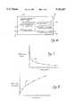
- FIG. 7is a plot of particle size versus fluid pressure
- FIG. 8is a plot of particle velocity versus fluid pressure
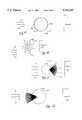
- FIG. 9is a schematic diagram illustrating a fluid particle, a source of electromagnetic energy, and a target surface according to the present invention.
- FIG. 10is a schematic diagram illustrating the "grenade” effect of the present invention.
- FIG. 11is a schematic diagram illustrating the "explosive ejection" effect of the present invention.
- FIG. 12is a schematic diagram illustrating the "explosive propulsion" effect of the present invention.
- FIG. 13is a schematic diagram illustrating a combination of FIGS. 10-12;
- FIG. 14is a schematic diagram illustrating the "cleanness" of cut obtained by the present invention.
- FIG. 15is a schematic diagram illustrating the roughness of cut obtained by prior art systems.
- FIG. 2shows an optical cutter according to the present invention.
- the optical cutter 13comprises many of the conventional elements shown in FIG. 1.
- a focusing optic 35is placed between the two metal cylindrical objects 19 and 21.
- the focusing optic 35prevents undesired dissipation of laser energy from the fiber guide tube 5. Specifically, energy from the fiber guide tube 5 dissipates slightly before being focused by the focusing optic 35.
- the focusing optic 35focuses energy from the fiber guide tube 5 into the fiber guide tube 23.
- the efficient transfer of laser energy from the fiber guide tube 5 to the fiber guide tube 23vitiates any need for the conventional air knife cooling system 11 (FIG. 1), since little laser energy is dissipated.
- the first fiber guide tube 5comprises a trunk fiberoptic, which comprises one of calcium fluoride (CaF), calcium oxide (CaO2), zirconium oxide (ZrO2), zirconium fluoride (ZrF), sapphire, hollow waveguide, liquid core, TeX glass, quartz silica, germanium sulfide, arsenic sulfide, and germanium oxide (GeO2).
- a trunk fiberopticwhich comprises one of calcium fluoride (CaF), calcium oxide (CaO2), zirconium oxide (ZrO2), zirconium fluoride (ZrF), sapphire, hollow waveguide, liquid core, TeX glass, quartz silica, germanium sulfide, arsenic sulfide, and germanium oxide (GeO2).
- FIG. 3is a block diagram illustrating the electromagnetically induced mechanical cutter of the present invention.
- An electromagnetic energy source 51is coupled to both a controller 53 and a delivery system 55.
- the delivery system 55imparts mechanical forces onto the target surface 57.
- the delivery system 55comprises a fiberoptic guide for routing the laser 51 into an interaction zone 59, located above the target surface 57.
- the delivery system 55further comprises an atomizer for delivering user-specified combinations of atomized fluid particles into the interaction zone 59.
- the controller 53controls various operating parameters of the laser 51, and further controls specific characteristics of the user-specified combination of atomized fluid particles output from the delivery system 55.
- FIG. 4shows a simple embodiment of the electromagnetically induced mechanical cutter of the present invention, in which a fiberoptic guide 61, an air tube 63, and a water tube 65 are placed within a hand-held housing 67.
- the water tube 65is preferably operated under a relatively low pressure
- the air tube 63is preferably operated under a relatively high pressure.
- the laser energy from the fiberoptic guide 61focuses onto a combination of air and water, from the air tube 63 and the water tube 65, at the interaction zone 59. Atomized fluid particles in the air and water mixture absorb energy from the laser energy of the fiberoptic tube 61, and explode. The explosive forces from these atomized fluid particles impart mechanical cutting forces onto the target 57.
- the prior art optical cutterfocuses laser energy on a target surface at an area A, for example, and the electromagnetically induced mechanical cutter of the present invention focuses laser energy into an interaction zone B, for example.
- the prior art optical cutteruses the laser energy directly to cut tissue, and the electromagnetically induced mechanical cutter of the present invention uses the laser energy to expand atomized fluid particles to thus impart mechanical cutting forces onto the target surface.
- the prior art optic cuttermust use a large amount of laser energy to cut the area of interest, and also must use a large amount of water to both cool this area of interest and remove cut tissue.
- the electromagnetically induced mechanical cutter of the present inventionuses a relatively small amount of water and, further, uses only a small amount of laser energy to expand atomized fluid particles generated from the water.
- wateris not needed to cool the area of surgery, since the exploded atomized fluid particles are cooled by exothermic reactions before they contact the target surface.
- atomized fluid particles of the present inventionare heated, expanded, and cooled before contacting the target surface.
- the electromagnetically induced mechanical cutter of the present inventionis thus capable of cutting without charring or discoloration.
- FIG. 5illustrates the presently preferred embodiment of the electromagnetically induced mechanical cutter.
- the atomizer for generating atomized fluid particlescomprises a nozzle 71, which may be interchanged with other nozzles (not shown) for obtaining various spatial distributions of the atomized fluid particles, according to the type of cut desired.
- a second nozzle 72shown in phantom lines, may also be used.
- the cutting power of the electromagnetically induced mechanical cutteris further controlled by the user control 75.
- the user control 75controls the air and water pressure entering into the nozzle 71.
- the nozzle 71is thus capable of generating many different user-specified combinations of atomized fluid particles and aerosolized sprays.
- Intense energyis emitted from the fiberoptic guide 23.
- This intense energyis preferably generated from a coherent source, such as a laser.
- the lasercomprises an erbium, chromium, yttrium, scandium, gallium garnet (Er, Cr:YSGG) solid state laser, which generates light having a wavelength in a range of 2.70 to 2.80 microns.
- this laserhas a wavelength of approximately 2.78 microns.
- the fluid emitted from the nozzle 71preferably comprises water, other fluids may be used and appropriate wavelengths of the electromagnetic energy source may be selected to allow for high absorption by the fluid.
- laser systemsinclude an erbium, yttrium, scandium, gallium garnet (Er:YSGG) solid state laser, which generates electromagnetic energy having a wavelength in a range of 2.70 to 2.80 microns; an erbium, yttrium, aluminum garnet (Er:YAG) solid state laser, which generates electromagnetic energy having a wavelength of 2.94 microns; chromium, thulium, erbium, yttrium, aluminum garnet (CTE:YAG) solid state laser, which generates electromagnetic energy having a wavelength of 2.69 microns; erbium, yttrium orthoaluminate (Er:YALO3) solid state laser, which generates electromagnetic energy having a wavelength in a range of 2.71 to 2.86 microns; holmium, yttrium, aluminum garnet (Ho:YAG) solid state laser, which generates electromagnetic energy having a wavelength of 2.10 microns; quadrupled neodymium, yttrium,
- the delivery system 55 for delivering the electromagnetic energyincludes a fiberoptic energy guide or equivalent which attaches to the laser system and travels to the desired work site.
- Fiberoptics or waveguidesare typically long, thin and lightweight, and are easily manipulated.
- Fiberopticscan be made of calcium fluoride (CaF), calcium oxide (CaO2), zirconium oxide (ZrO2), zirconium fluoride (ZrF), sapphire, hollow waveguide, liquid core, TeX glass, quartz silica, germanium sulfide, arsenic sulfide, germanium oxide (GeO2), and other materials.
- Other delivery systemsinclude devices comprising mirrors, lenses and other optical components where the energy travels through a cavity, is directed by various mirrors, and is focused onto the targeted cutting site with specific lenses.
- the preferred embodiment of light delivery for medical applications of the present inventionis through a fiberoptic conductor, because of its light weight, lower cost, and ability to be packaged inside of a handpiece of familiar size and weight to the surgeon, dentist, or clinician.
- non-fiberoptic systemsmay be used.
- the nozzle 71is employed to create an engineered combination of small particles of the chosen fluid.
- the nozzle 71may comprise several different designs including liquid only, air blast, air assist, swirl, solid cone, etc. When fluid exits the nozzle 71 at a given pressure and rate, it is transformed into particles of user-controllable sizes, velocities, and spatial distributions.
- FIG. 6illustrates a control panel 77 for allowing user-programmability of the atomized fluid particles.
- This control panelmay comprise, for example, a fluid particle size control 78, a fluid particle velocity control 79, a cone angle control 80, an average power control 81, a repetition rate 82, and a fiber selector 83.
- the cone anglemay be controlled, for example, by changing the physical structure of the nozzle 71.
- various nozzles 71may be interchangeably placed on the electromagnetically induced mechanical cutter.
- the physical structure of a single nozzle 71may be changed.
- FIG. 7illustrates a plot 85 of mean fluid particle size versus pressure. According to this figure, when the pressure through the nozzle 71 is increased, the mean fluid particle size of the atomized fluid particles decreases. The plot 87 of FIG. 8 shows that the mean fluid particle velocity of these atomized fluid particles increases with increasing pressure.
- materialsare removed from a target surface by mechanical cutting forces, instead of by conventional thermal cutting forces.
- Laser energyis used only to induce mechanical forces onto the targeted material.
- the atomized fluid particlesact as the medium for transforming the electromagnetic energy of the laser into the mechanical energy required to achieve the mechanical cutting effect of the present invention.
- the laser energy itselfis not directly absorbed by the targeted material.
- the mechanical interaction of the present inventionis safer, faster, and eliminates the negative thermal side-effects typically associated with conventional laser cutting systems.
- the fiberoptic guide 23(FIG. 5) can be placed into close proximity of the target surface. This fiberoptic guide 23, however, does not actually contact the target surface. Since the atomized fluid particles from the nozzle 71 are placed into the interaction zone 59, the purpose of the fiberoptic guide 23 is for placing laser energy into this interaction zone, as well.
- a novel feature of the present inventionis the formation of the fiberoptic guide 23 of sapphire. Regardless of the composition of the fiberoptic guide 23, however, another novel feature of the present invention is the cleaning effect of the air and water, from the nozzle 71, on the fiberoptic guide 23.
- each atomized fluid particlecontains a small amount of initial kinetic energy in the direction of the target surface.
- the spherical exterior surface of the fluid particleacts as a focusing lens to focus the energy into the water particle's interior.
- the water particle 101has an illuminated side 103, a shaded side 105, and a particle velocity 107.
- the focused electromagnetic energyis absorbed by the water particle 101, causing the interior of the water particle to heat and explode rapidly.
- This exothermic explosioncools the remaining portions of the exploded water particle 101.
- the surrounding atomized fluid particlesfurther enhance cooling of the portions of the exploded water particle 101.
- a pressure-waveis generated from this explosion.
- This pressure-wave, and the portions of the exploded water particle 101 of increased kinetic energyare directed toward the target surface 107.
- the incident portions from the original exploded water particle 101which are now traveling at high velocities with high kinetic energies, and the pressure-wave, impart strong, concentrated, mechanical forces onto the target surface 107.
- the present inventiondoes not require a thin layer of fluid. In fact, it is preferred that a thin layer of fluid does not cover the target surface, since this insulation layer would interfere with the above-described interaction process.
- FIGS. 10, 11 and 12illustrate various types of absorptions of the electromagnetic energy by atomized fluid particles.
- the nozzle 71is preferably configured to produce atomized sprays with a range of fluid particle sizes narrowly distributed about a mean value.
- the user input device for controlling cutting efficiencymay comprise a simple pressure and flow rate gauge 75 (FIG. 5) or may comprise a control panel as shown in FIG. 6, for example.
- a simple pressure and flow rate gauge 75FIG. 5
- FIG. 6for example.
- a user input specifying a deep penetration cutcauses the nozzle 71 to generate a relatively low density distribution of fluid particles
- a user input specifying a shallow penetration cutcauses the nozzle 71 to generate a relatively high density distribution of fluid particles.
- the user input devicecomprises the simple pressure and flow rate gauge 75 of FIG. 5, then a relatively low density distribution of relatively small fluid particles can be generated in response to a user input specifying a high cutting efficiency. Similarly, a relatively high density distribution of relatively large fluid particles can be generated in response to a user input specifying a low cutting efficiency.
- Other variationsare also possible.
- Hard tissuesinclude tooth enamel, tooth dentin, tooth cementum, bone, and cartilage.
- Soft tissueswhich the electromagnetically induced mechanical cutter of the present invention is also adapted to cut, include skin, mucosa, gingiva, muscle, heart, liver, kidney, brain, eye, and vessels. Other materials may include glass and semiconductor chip surfaces, for example.
- a usermay also adjust the combination of atomized fluid particles exiting the nozzle 71 to efficiently implement cooling and cleaning of the fiberoptics 23 (FIG. 5), as well.
- the combination of atomized fluid particlesmay comprise a distribution, velocity, and mean diameter to effectively cool the fiberoptic guide 23, while simultaneously keeping the fiberoptic guide 23 clean of particular debris which may be introduced thereon by the surgical site.
- electromagnetic energycontacts each atomized fluid particle 101 on its illuminated side 103 and penetrates the atomized fluid particle to a certain depth.
- the focused electromagnetic energyis absorbed by the fluid, inducing explosive vaporization of the atomized fluid particle 101.
- the diameters of the atomized fluid particlescan be less than, almost equal to, or greater than the wavelength of the incident electromagnetic energy.
- FIG. 10illustrates a case where the atomized fluid particle diameter is less than the wavelength of the electromagnetic energy (d ⁇ ).
- This casecauses the complete volume of fluid inside of the fluid particle 101 to absorb the laser energy, inducing explosive vaporization.
- the fluid particle 101explodes, ejecting its contents radially.
- Applicantsrefer to this phenomena as the "explosive grenade" effect.
- radial pressure-waves from the explosionare created and projected in the direction of propagation.
- the direction of propagationis toward the target surface 107, and in the presently preferred embodiment, both the laser energy and the atomized fluid particles are traveling substantially in the direction of propagation.
- the resulting portions from the explosion of the water particle 101, and the pressure-wave,produce the "chipping away” effect of cutting and removing of materials from the target surface 107.
- the small diameter of the fluid particle 101allows the laser energy to penetrate and to be absorbed violently within the entire volume of the liquid. Explosion of the fluid particle 101 can be analogized to an exploding grenade, which radially ejects energy and shrapnel.
- the water content of the fluid particle 101is evaporated due to the strong absorption within a small volume of liquid, and the pressure-waves created during this process produce the material cutting process.
- FIG. 11shows a case where the fluid particle 101 has a diameter, which is approximately equal to the wavelength of the electromagnetic energy (d ⁇ ).
- the laser energytravels through the fluid particle 101 before becoming absorbed by the fluid therein. Once absorbed, the fluid particle's shaded side heats up, and explosive vaporization occurs.
- internal particle fluidis violently ejected through the fluid particle's shaded side, and moves rapidly with the explosive pressure-wave toward the target surface.
- the laser energyis able to penetrate the fluid particle 101 and to be absorbed within a depth close to the size of the particle's diameter.
- the center of explosive vaporization in the case shown in FIG. 11is closer to the shaded side 105 of the moving fluid particle 101.
- the vaporized fluidis violently ejected through the particle's shaded side toward the target surface 107.
- a third case shown in FIG. 12is the "explosive propulsion" effect.
- the diameter of the fluid particleis larger than the wavelength of the electromagnetic energy (d> ⁇ ).
- the laser energypenetrates the fluid particle 101 only a small distance through the illuminated surface 103 and causes this illuminated surface 103 to vaporize.
- the vaporization of the illuminated surface 103tends to propel the remaining portion of the fluid particle 101 toward the targeted material surface 107.
- a portion of the mass of the initial fluid particle 101is converted into kinetic energy, to thereby propel the remaining portion of the fluid particle 101 toward the target surface with a high kinetic energy.
- This high kinetic energyis additive to the initial kinetic energy of the fluid particle 101.
- the effects shown in FIG. 12can be visualized as a micro-hydro rocket with a jet tail, which helps propel the particle with high velocity toward the target surface 107.
- the exploding vapor on the illuminated side 103thus supplements the particle's initial forward velocity.
- FIGS. 10-12The combination of FIGS. 10-12 is shown in FIG. 13.
- the nozzle 71produces the combination of atomized fluid particles which are transported into the interaction zone 59.
- the laser 51is focused on this interaction zone 59.
- Relatively small fluid particles 131explode via the "grenade” effect
- relatively large fluid particles 133explode via the "explosive propulsion” effect.
- the resulting pressure-waves 137 and exploded fluid particles 139impinge upon the target surface 107.
- FIG. 14illustrates the clean, high resolution cut produced by the electromagnetically induced mechanical cutter of the present invention. Unlike the cut of the prior art shown in FIG. 15, the cut of the present invention is clean and precise. Among other advantages, this cut provides an ideal bonding surface, is accurate, and does not stress remaining materials surrounding the cut.
Landscapes
- Physics & Mathematics (AREA)
- Optics & Photonics (AREA)
- Health & Medical Sciences (AREA)
- Engineering & Computer Science (AREA)
- Life Sciences & Earth Sciences (AREA)
- Mechanical Engineering (AREA)
- Plasma & Fusion (AREA)
- Veterinary Medicine (AREA)
- Surgery (AREA)
- Public Health (AREA)
- General Health & Medical Sciences (AREA)
- Animal Behavior & Ethology (AREA)
- Molecular Biology (AREA)
- Medical Informatics (AREA)
- Heart & Thoracic Surgery (AREA)
- Biomedical Technology (AREA)
- Otolaryngology (AREA)
- Oral & Maxillofacial Surgery (AREA)
- Dentistry (AREA)
- Epidemiology (AREA)
- Nuclear Medicine, Radiotherapy & Molecular Imaging (AREA)
- Electromagnetism (AREA)
- Laser Surgery Devices (AREA)
- Laser Beam Processing (AREA)
Abstract
Description
Claims (13)
Priority Applications (45)
| Application Number | Priority Date | Filing Date | Title |
|---|---|---|---|
| US08/522,503US5741247A (en) | 1995-08-31 | 1995-08-31 | Atomized fluid particles for electromagnetically induced cutting |
| US08/575,775US5785521A (en) | 1995-08-31 | 1995-12-20 | Fluid conditioning system |
| JP51058897AJP4073036B2 (en) | 1995-08-31 | 1996-08-30 | User-programmable combination of atomized particles for electromagnetic induction cutting |
| EP96931439AEP0847319B1 (en) | 1995-08-31 | 1996-08-30 | User programmable combination of atomized particles for electromagnetically induced cutting |
| CA002229848ACA2229848C (en) | 1995-08-31 | 1996-08-30 | User programmable combination of atomized particles for electromagnetically induced cutting |
| PCT/US1996/013960WO1997007928A2 (en) | 1995-08-31 | 1996-08-30 | User programmable combination of atomized particles for electromagnetically induced cutting |
| ES96931439TES2222483T3 (en) | 1995-08-31 | 1996-08-30 | PROGRAMMABLE COMBINATION BY THE USER OF PARTICLES ATOMIZED FOR CUTTING BY ELECTROMAGNETIC PROCEDURE. |
| DE69632139TDE69632139T2 (en) | 1995-08-31 | 1996-08-30 | USER-PROGRAMMABLE COMBINATION OF DUSTED PARTICLES FOR ELECTROMAGNETICALLY INDUCED CUTTING |
| CA002586117ACA2586117C (en) | 1995-08-31 | 1996-08-30 | User programmable combination of atomized particles for electromagnetically induced cutting |
| AT96931439TATE263652T1 (en) | 1995-08-31 | 1996-08-30 | USER PROGRAMMABLE COMBINATION OF SPUTTED PARTICLES FOR ELECTROMAGNETICALLY INDUCED CUTTING |
| AU70117/96AAU7011796A (en) | 1995-08-31 | 1996-08-30 | User programmable combination of atomized particles for electromagnetically induced cutting |
| US08/985,563US6610053B1 (en) | 1995-08-31 | 1997-12-05 | Methods of using atomized particles for electromagnetically induced cutting |
| US08/985,846US5968037A (en) | 1995-08-31 | 1997-12-05 | User programmable combination of atomized particles for electromagnetically induced cutting |
| US09/188,072US6254597B1 (en) | 1995-08-31 | 1998-11-06 | Tissue remover and method |
| US09/256,697US6350123B1 (en) | 1995-08-31 | 1999-02-24 | Fluid conditioning system |
| US09/270,311US6231567B1 (en) | 1995-08-31 | 1999-03-16 | Material remover and method |
| US09/822,981US6567582B1 (en) | 1995-08-31 | 2001-03-30 | Fiber tip fluid output device |
| US09/997,550US6561803B1 (en) | 1995-08-31 | 2001-11-27 | Fluid conditioning system |
| US10/177,743US6744790B1 (en) | 1995-08-31 | 2002-06-21 | Device for reduction of thermal lensing |
| US10/404,683US7187822B2 (en) | 1995-08-31 | 2003-04-01 | Fiber tip fluid output device |
| US10/435,325US7320594B1 (en) | 1995-08-31 | 2003-05-09 | Fluid and laser system |
| US10/624,967US20040092925A1 (en) | 1995-08-31 | 2003-07-21 | Methods of using atomized particles for electromagnetically induced cutting |
| US11/033,043US20050283143A1 (en) | 1995-08-31 | 2005-01-10 | Tissue remover and method |
| US11/033,044US20050281887A1 (en) | 1995-08-31 | 2005-01-10 | Fluid conditioning system |
| CA002552969ACA2552969A1 (en) | 1995-08-31 | 2005-01-10 | Tissue remover and method |
| AU2005206812AAU2005206812A1 (en) | 1995-08-31 | 2005-01-10 | Tissue remover and method |
| EP05711358AEP1765179A4 (en) | 1995-08-31 | 2005-01-10 | FABRIC EXTRACTOR AND METHOD THEREOF |
| JP2006549535AJP2007528239A (en) | 1995-08-31 | 2005-01-10 | Tissue removal apparatus and method |
| PCT/US2005/000852WO2005070154A2 (en) | 1995-08-31 | 2005-01-10 | Tissue remover and method |
| US11/033,441US7620290B2 (en) | 1995-08-31 | 2005-01-10 | Modified-output fiber optic tips |
| US11/033,032US20060241574A1 (en) | 1995-08-31 | 2005-01-11 | Electromagnetic energy distributions for electromagnetically induced disruptive cutting |
| US11/186,409US20070208328A1 (en) | 1995-08-31 | 2005-07-20 | Contra-angel rotating handpiece having tactile-feedback tip ferrule |
| US11/330,388US20060240381A1 (en) | 1995-08-31 | 2006-01-10 | Fluid conditioning system |
| PCT/US2006/000989WO2006074486A2 (en) | 1995-08-31 | 2006-01-10 | Fluid conditioning system |
| US11/523,492US7696466B2 (en) | 1995-08-31 | 2006-09-18 | Electromagnetic energy distributions for electromagnetically induced mechanical cutting |
| US11/644,155US7424199B2 (en) | 1995-08-31 | 2006-12-22 | Fiber tip fluid output device |
| US11/823,149US20080151953A1 (en) | 1995-08-31 | 2007-06-26 | Electromagnet energy distributions for electromagnetically induced mechanical cutting |
| US12/190,690US8023795B2 (en) | 1995-08-31 | 2008-08-13 | Fiber tip fluid output device |
| US12/245,743US8033825B2 (en) | 1995-08-31 | 2008-10-04 | Fluid and pulsed energy output system |
| US12/336,528US20090105707A1 (en) | 1995-08-31 | 2008-12-16 | Drill and flavored fluid particles combination |
| US12/368,276US20090143775A1 (en) | 1995-08-31 | 2009-02-09 | Medical laser having controlled-temperature and sterilized fluid output |
| US12/437,485US20090281531A1 (en) | 1995-08-31 | 2009-05-07 | Interventional and therapeutic electromagnetic energy systems |
| US12/571,338US20100086892A1 (en) | 1995-08-31 | 2009-09-30 | Modified-output fiber optic tips |
| US12/693,370US20100125291A1 (en) | 1995-08-31 | 2010-01-25 | Drill and flavored fluid particles combination |
| US13/016,827US20110129789A1 (en) | 1995-08-31 | 2011-01-28 | Drill and flavored fluid particles combination |
Applications Claiming Priority (1)
| Application Number | Priority Date | Filing Date | Title |
|---|---|---|---|
| US08/522,503US5741247A (en) | 1995-08-31 | 1995-08-31 | Atomized fluid particles for electromagnetically induced cutting |
Related Parent Applications (3)
| Application Number | Title | Priority Date | Filing Date |
|---|---|---|---|
| US08/575,775ContinuationUS5785521A (en) | 1995-08-31 | 1995-12-20 | Fluid conditioning system |
| US59998496AContinuation-In-Part | 1995-08-31 | 1996-02-14 | |
| US99524197AContinuation-In-Part | 1995-08-31 | 1997-12-17 |
Related Child Applications (5)
| Application Number | Title | Priority Date | Filing Date |
|---|---|---|---|
| US08/575,775Continuation-In-PartUS5785521A (en) | 1995-08-31 | 1995-12-20 | Fluid conditioning system |
| US08/903,187Continuation-In-PartUS6288499B1 (en) | 1995-08-31 | 1997-06-12 | Electromagnetic energy distributions for electromagnetically induced mechanical cutting |
| US08/985,563DivisionUS6610053B1 (en) | 1995-08-31 | 1997-12-05 | Methods of using atomized particles for electromagnetically induced cutting |
| US98551397AContinuation | 1995-08-31 | 1997-12-05 | |
| US99524197AContinuation | 1995-08-31 | 1997-12-17 |
Publications (1)
| Publication Number | Publication Date |
|---|---|
| US5741247Atrue US5741247A (en) | 1998-04-21 |
Family
ID=24081134
Family Applications (4)
| Application Number | Title | Priority Date | Filing Date |
|---|---|---|---|
| US08/522,503Expired - LifetimeUS5741247A (en) | 1995-08-31 | 1995-08-31 | Atomized fluid particles for electromagnetically induced cutting |
| US08/985,846Expired - LifetimeUS5968037A (en) | 1995-08-31 | 1997-12-05 | User programmable combination of atomized particles for electromagnetically induced cutting |
| US08/985,563Expired - LifetimeUS6610053B1 (en) | 1995-08-31 | 1997-12-05 | Methods of using atomized particles for electromagnetically induced cutting |
| US10/624,967AbandonedUS20040092925A1 (en) | 1995-08-31 | 2003-07-21 | Methods of using atomized particles for electromagnetically induced cutting |
Family Applications After (3)
| Application Number | Title | Priority Date | Filing Date |
|---|---|---|---|
| US08/985,846Expired - LifetimeUS5968037A (en) | 1995-08-31 | 1997-12-05 | User programmable combination of atomized particles for electromagnetically induced cutting |
| US08/985,563Expired - LifetimeUS6610053B1 (en) | 1995-08-31 | 1997-12-05 | Methods of using atomized particles for electromagnetically induced cutting |
| US10/624,967AbandonedUS20040092925A1 (en) | 1995-08-31 | 2003-07-21 | Methods of using atomized particles for electromagnetically induced cutting |
Country Status (1)
| Country | Link |
|---|---|
| US (4) | US5741247A (en) |
Cited By (113)
| Publication number | Priority date | Publication date | Assignee | Title |
|---|---|---|---|---|
| WO1998055888A1 (en)* | 1997-06-06 | 1998-12-10 | Optomedic Medical Technologies Ltd. | Laser probe |
| US5968037A (en)* | 1995-08-31 | 1999-10-19 | Biolase Technology, Inc. | User programmable combination of atomized particles for electromagnetically induced cutting |
| US6090102A (en)* | 1997-05-12 | 2000-07-18 | Irvision, Inc. | Short pulse mid-infrared laser source for surgery |
| US6231567B1 (en)* | 1995-08-31 | 2001-05-15 | Biolase Technology Inc. | Material remover and method |
| US6254597B1 (en)* | 1995-08-31 | 2001-07-03 | Biolase Technology, Inc. | Tissue remover and method |
| US6350123B1 (en)* | 1995-08-31 | 2002-02-26 | Biolase Technology, Inc. | Fluid conditioning system |
| WO2002066254A1 (en)* | 2001-02-15 | 2002-08-29 | Kodak Polychrome Graphics Company, Ltd. | Method for making a printing plate and printing plate |
| US6464694B1 (en) | 1997-10-30 | 2002-10-15 | Sonique Surgical Systems, Inc. | Laser-assisted liposuction method and apparatus |
| US20020183728A1 (en)* | 2001-05-14 | 2002-12-05 | Yitzhak Rosenberg | Laser probe |
| US6544256B1 (en)* | 1998-04-24 | 2003-04-08 | Biolase Technology, Inc. | Electromagnetically induced cutting with atomized fluid particles for dermatological applications |
| US20030207232A1 (en)* | 2001-08-23 | 2003-11-06 | Todd Robert H | Method and apparatus for drilling teeth with a pressurized water stream |
| US20040068256A1 (en)* | 1997-11-06 | 2004-04-08 | Biolase Technology, Inc. | Tissue remover and method |
| US20040224288A1 (en)* | 2003-05-08 | 2004-11-11 | Eric Bornstein | Instrument for delivery of optical energy to the dental root canal system for hidden bacterial and live biofilm thermolysis |
| US6824540B1 (en)* | 2000-11-06 | 2004-11-30 | Surgilight, Inc. | Apparatus and methods for the treatment of presbyopia using fiber-coupled-lasers |
| US20050103758A1 (en)* | 2003-11-14 | 2005-05-19 | Charles Otis | Laser micromachining and methods of same |
| US20050107774A1 (en)* | 1999-05-03 | 2005-05-19 | Lin J. T. | Methods and apparatus for presbyopia correction using ultraviolet and infrared lasers |
| WO2005070151A2 (en) | 2004-01-08 | 2005-08-04 | Biolase Technology, Inc. | Electromagnetic energy distributions for electromagnetically induced mechanical cutting |
| US20050256516A1 (en)* | 2004-01-08 | 2005-11-17 | Dmitri Boutoussov | Illumination device and related methods |
| EP1016328B1 (en)* | 1997-06-12 | 2005-12-07 | Biolase Technology, Inc. | Electromagnetic energy distributions for electromagnetically induced mechanical cutting |
| US20050281887A1 (en)* | 1995-08-31 | 2005-12-22 | Rizoiu Ioana M | Fluid conditioning system |
| US20060033963A1 (en)* | 2004-08-10 | 2006-02-16 | Hirobumi Nishida | Image processing device, image processing method, image processing program, and recording medium |
| US20060099548A1 (en)* | 2004-08-13 | 2006-05-11 | Rizoiu Ioana M | Caries detection using timing differentials between excitation and return pulses |
| US20060126680A1 (en)* | 2004-07-27 | 2006-06-15 | Dmitri Boutoussov | Dual pulse-width medical laser |
| US20060135955A1 (en)* | 2003-01-18 | 2006-06-22 | Shadduck John H | Medical instrument and method of use |
| US20060142745A1 (en)* | 2004-08-13 | 2006-06-29 | Dmitri Boutoussov | Dual pulse-width medical laser with presets |
| US20060167450A1 (en)* | 2005-01-14 | 2006-07-27 | Johnson Kristin D | Vessel sealer and divider with rotating sealer and cutter |
| US20060224154A1 (en)* | 2001-12-07 | 2006-10-05 | Shadduck John H | Medical instrument and method of use |
| US20060240381A1 (en)* | 1995-08-31 | 2006-10-26 | Biolase Technology, Inc. | Fluid conditioning system |
| US20060241574A1 (en)* | 1995-08-31 | 2006-10-26 | Rizoiu Ioana M | Electromagnetic energy distributions for electromagnetically induced disruptive cutting |
| US20070016176A1 (en)* | 2004-08-13 | 2007-01-18 | Dmitri Boutoussov | Laser handpiece architecture and methods |
| US20070032785A1 (en)* | 2005-08-03 | 2007-02-08 | Jennifer Diederich | Tissue evacuation device |
| US20070055220A1 (en)* | 2003-11-14 | 2007-03-08 | Jui-Teng Lin | Methods and systems for treating presbyopia via laser ablation |
| US20070060917A1 (en)* | 2002-06-21 | 2007-03-15 | Biolase Technology, Inc. | High-efficiency, side-pumped diode laser system |
| US20070208328A1 (en)* | 1995-08-31 | 2007-09-06 | Dmitri Boutoussov | Contra-angel rotating handpiece having tactile-feedback tip ferrule |
| US20070265604A1 (en)* | 2006-03-03 | 2007-11-15 | Davenport Scott A | Aesthetic treatment for wrinkle reduction and rejuvenation |
| USRE40002E1 (en) | 1998-11-10 | 2008-01-15 | Surgilight, Inc. | Treatment of presbyopia and other eye disorders using a scanning laser system |
| US7320594B1 (en)* | 1995-08-31 | 2008-01-22 | Biolase Technology, Inc. | Fluid and laser system |
| US20080025671A1 (en)* | 2004-07-20 | 2008-01-31 | Biolase Technology, Inc. | Contra-angle rotating handpiece having tactile-feedback tip ferrule |
| US20080033411A1 (en)* | 2006-07-14 | 2008-02-07 | Biolase Technology, Inc. | High efficiency electromagnetic laser energy cutting device |
| US20080032251A1 (en)* | 2006-07-19 | 2008-02-07 | Mau-Song Chou | Laser carious region ablation |
| US20080065057A1 (en)* | 2001-06-21 | 2008-03-13 | Biolase Technology, Inc. | High-efficiency, side-pumped diode laser system |
| US20080069172A1 (en)* | 2006-09-18 | 2008-03-20 | Rizoiu Ioana M | Electromagnetic energy distributions for electromagnetically induced mechanical cutting |
| US20080157690A1 (en)* | 2001-05-02 | 2008-07-03 | Biolase Technology, Inc. | Electromagnetic energy distributions for electromagnetically induced mechanical cutting |
| US20080181278A1 (en)* | 2007-01-25 | 2008-07-31 | Dmitri Boutoussov | Electromagnetic energy output system |
| US20080181261A1 (en)* | 2007-01-25 | 2008-07-31 | Dmitri Boutoussov | Electromagnetic energy output system |
| US20080203280A1 (en)* | 2007-01-25 | 2008-08-28 | Rizoiu Ioana M | Target-close electromagnetic energy emitting device |
| US20080219629A1 (en)* | 2004-01-08 | 2008-09-11 | Blolase Technology, Inc. | Modified-output fiber optic tips |
| US20080276192A1 (en)* | 2007-05-03 | 2008-11-06 | Biolase Technology, Inc. | Method and apparatus for controlling an electromagnetic energy output system |
| US20090067189A1 (en)* | 2005-06-07 | 2009-03-12 | Dmitri Boutoussov | Contra-angle rotating handpiece having tactile-feedback tip ferrule |
| WO2009039456A1 (en)* | 2007-09-19 | 2009-03-26 | Biolase Technology, Inc. | Probes and biofluids for treating and removing deposits from tissue surfaces |
| US20090105703A1 (en)* | 2000-12-09 | 2009-04-23 | Shadduck John H | Method for treating tissue |
| US20090141752A1 (en)* | 2004-07-27 | 2009-06-04 | Rizoiu Ioana M | Dual pulse-width medical laser with presets |
| US20090143775A1 (en)* | 1995-08-31 | 2009-06-04 | Rizoiu Ioana M | Medical laser having controlled-temperature and sterilized fluid output |
| US20090149846A1 (en)* | 2003-10-07 | 2009-06-11 | Tsunami Medtech, Llc | Medical system and method of use |
| US20090216220A1 (en)* | 2008-02-20 | 2009-08-27 | Tsunami Medtech, Llc | Medical system and method of use |
| US20090225060A1 (en)* | 2007-05-03 | 2009-09-10 | Rizoiu Ioana M | Wrist-mounted laser with animated, page-based graphical user-interface |
| US20090298004A1 (en)* | 1997-11-06 | 2009-12-03 | Rizoiu Ioana M | Tunnelling probe |
| US20100114082A1 (en)* | 2008-10-06 | 2010-05-06 | Sharma Virender K | Method and Apparatus for the Ablation of Endometrial Tissue |
| US20100125291A1 (en)* | 1995-08-31 | 2010-05-20 | Rizoiu Ioana M | Drill and flavored fluid particles combination |
| WO2010062969A1 (en) | 2008-11-29 | 2010-06-03 | Biolase Technology, Inc. | Non-contact handpiece for laser tissue cutting |
| US20100137851A1 (en)* | 2008-12-01 | 2010-06-03 | Industrial Technology Research Institute | Laser surgical apparatus |
| US20100151406A1 (en)* | 2004-01-08 | 2010-06-17 | Dmitri Boutoussov | Fluid conditioning system |
| US20100185188A1 (en)* | 1997-06-12 | 2010-07-22 | Dmitri Boutoussov | Electromagnetically induced treatment devices and methods |
| US20100204688A1 (en)* | 2008-09-09 | 2010-08-12 | Michael Hoey | Medical system and method of use |
| US20100262133A1 (en)* | 2009-02-03 | 2010-10-14 | Tsunami Medtech, Llc | Medical systems and methods for ablating and absorbing tissue |
| WO2011053604A1 (en) | 2009-10-26 | 2011-05-05 | Biolase Technology, Inc. | High power radiation source with active-media housing |
| US20110129789A1 (en)* | 1995-08-31 | 2011-06-02 | Biolase Technology, Inc. | Drill and flavored fluid particles combination |
| US20110270241A1 (en)* | 2005-06-24 | 2011-11-03 | Biolase Technology, Inc. | Visual feedback implements for electromagnetic energy output devices |
| US8187269B2 (en) | 1998-03-27 | 2012-05-29 | Tsunami Medtech, Llc | Medical instruments and techniques for treating pulmonary disorders |
| DE202005022082U1 (en) | 2004-01-08 | 2013-03-14 | Biolase Inc. | Fiber optic tips with modified output |
| US20130066263A1 (en)* | 2010-03-16 | 2013-03-14 | Snu R&Db Foundation | Microjet drug delivery system and microjet injector |
| US8579888B2 (en) | 2008-06-17 | 2013-11-12 | Tsunami Medtech, Llc | Medical probes for the treatment of blood vessels |
| US8900223B2 (en) | 2009-11-06 | 2014-12-02 | Tsunami Medtech, Llc | Tissue ablation systems and methods of use |
| US20150025445A1 (en)* | 2013-07-18 | 2015-01-22 | International Business Machines Corporation | Laser-assisted transdermal delivery of nanoparticulates and hydrogels |
| US20150150650A1 (en)* | 2011-09-30 | 2015-06-04 | Biolase, Inc. | Pressure Wave Root Canal Cleaning System |
| US9161801B2 (en) | 2009-12-30 | 2015-10-20 | Tsunami Medtech, Llc | Medical system and method of use |
| EP2937055A1 (en) | 2008-10-15 | 2015-10-28 | Biolase, Inc. | Satellite-platformed electromagnetic energy treatment device |
| US20160184022A1 (en)* | 2013-03-13 | 2016-06-30 | The Spectranetics Corporation | Laser-induced pressure wave emitting catheter sheath |
| US9433457B2 (en) | 2000-12-09 | 2016-09-06 | Tsunami Medtech, Llc | Medical instruments and techniques for thermally-mediated therapies |
| US9561066B2 (en) | 2008-10-06 | 2017-02-07 | Virender K. Sharma | Method and apparatus for tissue ablation |
| US9561068B2 (en) | 2008-10-06 | 2017-02-07 | Virender K. Sharma | Method and apparatus for tissue ablation |
| US9561067B2 (en) | 2008-10-06 | 2017-02-07 | Virender K. Sharma | Method and apparatus for tissue ablation |
| US20170333132A1 (en)* | 2014-12-30 | 2017-11-23 | The Spectranetics Corporation | Laser-induced pressure wave emitting catheter sheath |
| US20180008348A1 (en)* | 2014-08-25 | 2018-01-11 | The Spectranetics Corporation | Liquid laser-induced pressure wave emitting catheter sheath |
| US9943353B2 (en) | 2013-03-15 | 2018-04-17 | Tsunami Medtech, Llc | Medical system and method of use |
| US10064697B2 (en) | 2008-10-06 | 2018-09-04 | Santa Anna Tech Llc | Vapor based ablation system for treating various indications |
| US10130424B2 (en) | 2014-01-31 | 2018-11-20 | Biolase, Inc. | Multiple beam laser treatment device |
| US20190008608A1 (en)* | 2012-05-14 | 2019-01-10 | Convergent Dental, Inc. | Apparatus and method for controlled fluid cooling during laser based dental treatments |
| US10179019B2 (en) | 2014-05-22 | 2019-01-15 | Aegea Medical Inc. | Integrity testing method and apparatus for delivering vapor to the uterus |
| US10238446B2 (en) | 2010-11-09 | 2019-03-26 | Aegea Medical Inc. | Positioning method and apparatus for delivering vapor to the uterus |
| US10299856B2 (en) | 2014-05-22 | 2019-05-28 | Aegea Medical Inc. | Systems and methods for performing endometrial ablation |
| EP3590457A2 (en) | 2013-12-31 | 2020-01-08 | Biolase, Inc. | Dual wavelength laser treatment device |
| EP3666209A2 (en) | 2010-11-04 | 2020-06-17 | Biolase, Inc. | Initiation sequences for ramping-up pulse power in a medical laser having high-intensity leading subpulses |
| US10695126B2 (en) | 2008-10-06 | 2020-06-30 | Santa Anna Tech Llc | Catheter with a double balloon structure to generate and apply a heated ablative zone to tissue |
| US10758292B2 (en) | 2007-08-23 | 2020-09-01 | Aegea Medical Inc. | Uterine therapy device and method |
| EP3578292B1 (en) | 2011-09-21 | 2020-11-25 | Align Technology, Inc. | Method of laser cutting |
| US10881442B2 (en) | 2011-10-07 | 2021-01-05 | Aegea Medical Inc. | Integrity testing method and apparatus for delivering vapor to the uterus |
| CN113143409A (en)* | 2021-05-14 | 2021-07-23 | 桂林电子科技大学 | Low-damage water mist mediated laser biological hard tissue treatment device and using method thereof |
| CN113180821A (en)* | 2021-06-07 | 2021-07-30 | 江西麦帝施科技有限公司 | Laser surgery system with cutting and blood coagulation integrated optical fiber cutter head |
| US11331037B2 (en) | 2016-02-19 | 2022-05-17 | Aegea Medical Inc. | Methods and apparatus for determining the integrity of a bodily cavity |
| US11331140B2 (en) | 2016-05-19 | 2022-05-17 | Aqua Heart, Inc. | Heated vapor ablation systems and methods for treating cardiac conditions |
| US11369741B2 (en) | 2016-11-03 | 2022-06-28 | Snu R&Db Foundation | Automatic recharging micro-jet drug injection device preventing jet speed down problem of repeated injection |
| US11400219B2 (en) | 2016-07-28 | 2022-08-02 | Snu R&Db Foundation | Microjet drug delivery system with enhanced drug penetration performance by fractional laser pre-ablation |
| US11583462B2 (en) | 2013-03-12 | 2023-02-21 | Biolase, Inc. | Dental laser unit with communication link to assistance center |
| US11684421B2 (en) | 2006-08-24 | 2023-06-27 | Pipstek, Llc | Dental and medical treatments and procedures |
| US11701202B2 (en) | 2013-06-26 | 2023-07-18 | Sonendo, Inc. | Apparatus and methods for filling teeth and root canals |
| USD997355S1 (en) | 2020-10-07 | 2023-08-29 | Sonendo, Inc. | Dental treatment instrument |
| US11806066B2 (en) | 2018-06-01 | 2023-11-07 | Santa Anna Tech Llc | Multi-stage vapor-based ablation treatment methods and vapor generation and delivery systems |
| US11918432B2 (en) | 2006-04-20 | 2024-03-05 | Sonendo, Inc. | Apparatus and methods for treating root canals of teeth |
| US12114924B2 (en) | 2006-08-24 | 2024-10-15 | Pipstek, Llc | Treatment system and method |
| US12186151B2 (en) | 2010-10-21 | 2025-01-07 | Sonendo, Inc. | Apparatus, methods, and compositions for endodontic treatments |
| US12268565B2 (en) | 2009-11-13 | 2025-04-08 | Sonendo, Inc. | Liquid jet apparatus and methods for dental treatments |
| US12364537B2 (en) | 2016-05-02 | 2025-07-22 | Santa Anna Tech Llc | Catheter with a double balloon structure to generate and apply a heated ablative zone to tissue |
Families Citing this family (29)
| Publication number | Priority date | Publication date | Assignee | Title |
|---|---|---|---|---|
| US7620290B2 (en)* | 1995-08-31 | 2009-11-17 | Biolase Technology, Inc. | Modified-output fiber optic tips |
| US7187822B2 (en)* | 1995-08-31 | 2007-03-06 | Biolase Technology, Inc. | Fiber tip fluid output device |
| US6530212B1 (en)* | 2000-02-25 | 2003-03-11 | Photonic Associates | Laser plasma thruster |
| US6953461B2 (en) | 2002-05-16 | 2005-10-11 | Tissuelink Medical, Inc. | Fluid-assisted medical devices, systems and methods |
| ES2306706T3 (en) | 2000-03-06 | 2008-11-16 | Salient Surgical Technologies, Inc. | FLUID SUPPLY SYSTEM AND CONTROLLER FOR ELECTROCHURGICAL DEVICES. |
| US6558385B1 (en) | 2000-09-22 | 2003-05-06 | Tissuelink Medical, Inc. | Fluid-assisted medical device |
| US6689131B2 (en) | 2001-03-08 | 2004-02-10 | Tissuelink Medical, Inc. | Electrosurgical device having a tissue reduction sensor |
| US8048070B2 (en) | 2000-03-06 | 2011-11-01 | Salient Surgical Technologies, Inc. | Fluid-assisted medical devices, systems and methods |
| US7811282B2 (en) | 2000-03-06 | 2010-10-12 | Salient Surgical Technologies, Inc. | Fluid-assisted electrosurgical devices, electrosurgical unit with pump and methods of use thereof |
| DE10130999A1 (en)* | 2000-06-29 | 2002-04-18 | D M S Co | Multifunction cleaning module of a manufacturing device for flat screens and cleaning device using the same |
| AU2002357166A1 (en) | 2001-12-12 | 2003-06-23 | Tissuelink Medical, Inc. | Fluid-assisted medical devices, systems and methods |
| US7012216B2 (en)* | 2002-02-08 | 2006-03-14 | Honeywell International | Hand-held laser welding wand having internal coolant and gas delivery conduits |
| WO2004039416A2 (en) | 2002-10-29 | 2004-05-13 | Tissuelink Medical, Inc. | Fluid-assisted electrosurgical scissors and methods |
| US7727232B1 (en) | 2004-02-04 | 2010-06-01 | Salient Surgical Technologies, Inc. | Fluid-assisted medical devices and methods |
| CN101111538B (en)* | 2004-12-30 | 2011-03-30 | 3M创新有限公司 | Fluoropolymer nanoparticle coating composition |
| US7550693B2 (en)* | 2005-02-04 | 2009-06-23 | Honeywell International Inc. | Hand-held laser welding wand with improved optical assembly serviceability features |
| EP1883381A4 (en)* | 2005-05-25 | 2010-03-17 | Biolase Tech Inc | Electromagnetic energy emitting device with increased spot size |
| USD567374S1 (en)* | 2006-03-16 | 2008-04-22 | Aaron Medical Industries, Inc. | Electrode |
| GB2452103B (en) | 2007-01-05 | 2011-08-31 | Arthrocare Corp | Electrosurgical system with suction control apparatus and system |
| JP5115088B2 (en)* | 2007-08-10 | 2013-01-09 | セイコーエプソン株式会社 | Surgical tool |
| US9358063B2 (en) | 2008-02-14 | 2016-06-07 | Arthrocare Corporation | Ablation performance indicator for electrosurgical devices |
| EP2174615A1 (en)* | 2008-10-10 | 2010-04-14 | W & H Dentalwerk Bürmoos GmbH | Medical, in particular dental, treatment device |
| US8372067B2 (en) | 2009-12-09 | 2013-02-12 | Arthrocare Corporation | Electrosurgery irrigation primer systems and methods |
| US9131597B2 (en)* | 2011-02-02 | 2015-09-08 | Arthrocare Corporation | Electrosurgical system and method for treating hard body tissue |
| US9622833B2 (en) | 2011-09-02 | 2017-04-18 | Convergent Dental, Inc. | Laser based computer controlled dental preparation system |
| US9801678B2 (en) | 2013-03-13 | 2017-10-31 | Arthrocare Corporation | Method and system of controlling conductive fluid flow during an electrosurgical procedure |
| US9987037B2 (en)* | 2014-05-07 | 2018-06-05 | Massachusetts Institute Of Technology | Debridement apparatus using linear lorentz-force motors |
| US10814425B2 (en)* | 2016-12-15 | 2020-10-27 | John Murkin | Compact laser machining head |
| RU2734535C1 (en)* | 2017-03-20 | 2020-10-20 | Тэхан ЯН | Welding torch |
Citations (8)
| Publication number | Priority date | Publication date | Assignee | Title |
|---|---|---|---|---|
| US4826431A (en)* | 1986-06-12 | 1989-05-02 | Kabushiki Kaisha Morita Seisakusho | Medical laser handpiece |
| US5151029A (en)* | 1988-12-21 | 1992-09-29 | Endo Technic Corporation | Removing physiologic tissue from a tooth canal |
| US5199870A (en)* | 1989-04-11 | 1993-04-06 | Aesculap Ag | Process for destroying and removing material from teeth |
| US5267856A (en)* | 1991-09-20 | 1993-12-07 | Premier Laser Systems, Inc. | Laser surgical method |
| US5318562A (en)* | 1992-03-10 | 1994-06-07 | Laser Endo Technic Corporation | Handpiece for delivering laser radiation |
| US5388988A (en)* | 1992-08-10 | 1995-02-14 | Siemens Aktiengesellschaft | Dental instrument for treating teeth with a laser beam |
| US5401171A (en)* | 1992-07-20 | 1995-03-28 | Paghdiwala; Abid F. | Dental laser device and method |
| US5409376A (en)* | 1993-03-10 | 1995-04-25 | Murphy; Quentin M. | Apparatus and process for laser-assisted driling |
Family Cites Families (22)
| Publication number | Priority date | Publication date | Assignee | Title |
|---|---|---|---|---|
| US5552675A (en) | 1959-04-08 | 1996-09-03 | Lemelson; Jerome H. | High temperature reaction apparatus |
| GB1242123A (en) | 1968-11-12 | 1971-08-11 | Nat Res Dev | Improvements relating to a method and apparatus for laser beam cutting |
| JPS5157283A (en) | 1974-11-15 | 1976-05-19 | Nippon Electric Co | Handotaikibanno bunkatsuhoho |
| JPS5945092A (en)* | 1982-09-06 | 1984-03-13 | Fuji Denpa Koki Kk | Laser working device |
| GB8428411D0 (en) | 1984-11-09 | 1984-12-19 | Micra Ltd | Laser knives |
| DE3506249A1 (en)* | 1985-02-22 | 1986-08-28 | Messerschmitt-Bölkow-Blohm GmbH, 8012 Ottobrunn | METHOD AND DEVICE FOR SMASHING A SOLID BODY |
| US4724299A (en)* | 1987-04-15 | 1988-02-09 | Quantum Laser Corporation | Laser spray nozzle and method |
| US5092773A (en) | 1989-01-18 | 1992-03-03 | Endo Technic Corporation | Method and apparatus for filling a tooth canal |
| US5059200A (en)* | 1990-04-06 | 1991-10-22 | John Tulip | Laser lithotripsy |
| US5092864A (en)* | 1990-04-30 | 1992-03-03 | Microfab Technologies, Inc. | Method and apparatus for improved laser surgery |
| US5713845A (en)* | 1991-10-29 | 1998-02-03 | Thermolase Corporation | Laser assisted drug delivery |
| DE4138468A1 (en) | 1991-11-22 | 1993-06-03 | Stiftung Fuer Lasertechnologie | Laser device for removing material from biological surfaces - has liq.-gas spray units which intersect laser sepn. ensuring that surrounding areas are not dehydrated |
| US5374266A (en)* | 1991-11-27 | 1994-12-20 | Kabushiki Kaisha Morita Seisakusho | Medical laser treatment device |
| US5334019A (en) | 1991-12-06 | 1994-08-02 | American Dental Technologies, Inc. | Dental air abrasive system |
| US6350123B1 (en)* | 1995-08-31 | 2002-02-26 | Biolase Technology, Inc. | Fluid conditioning system |
| US6669685B1 (en)* | 1997-11-06 | 2003-12-30 | Biolase Technology, Inc. | Tissue remover and method |
| US6567582B1 (en)* | 1995-08-31 | 2003-05-20 | Biolase Tech Inc | Fiber tip fluid output device |
| US5741247A (en)* | 1995-08-31 | 1998-04-21 | Biolase Technology, Inc. | Atomized fluid particles for electromagnetically induced cutting |
| US6254597B1 (en)* | 1995-08-31 | 2001-07-03 | Biolase Technology, Inc. | Tissue remover and method |
| US5785521A (en)* | 1995-08-31 | 1998-07-28 | Biolase Technology, Inc. | Fluid conditioning system |
| US6288499B1 (en)* | 1997-06-12 | 2001-09-11 | Biolase Technology, Inc. | Electromagnetic energy distributions for electromagnetically induced mechanical cutting |
| US6544256B1 (en)* | 1998-04-24 | 2003-04-08 | Biolase Technology, Inc. | Electromagnetically induced cutting with atomized fluid particles for dermatological applications |
- 1995
- 1995-08-31USUS08/522,503patent/US5741247A/ennot_activeExpired - Lifetime
- 1997
- 1997-12-05USUS08/985,846patent/US5968037A/ennot_activeExpired - Lifetime
- 1997-12-05USUS08/985,563patent/US6610053B1/ennot_activeExpired - Lifetime
- 2003
- 2003-07-21USUS10/624,967patent/US20040092925A1/ennot_activeAbandoned
Patent Citations (8)
| Publication number | Priority date | Publication date | Assignee | Title |
|---|---|---|---|---|
| US4826431A (en)* | 1986-06-12 | 1989-05-02 | Kabushiki Kaisha Morita Seisakusho | Medical laser handpiece |
| US5151029A (en)* | 1988-12-21 | 1992-09-29 | Endo Technic Corporation | Removing physiologic tissue from a tooth canal |
| US5199870A (en)* | 1989-04-11 | 1993-04-06 | Aesculap Ag | Process for destroying and removing material from teeth |
| US5267856A (en)* | 1991-09-20 | 1993-12-07 | Premier Laser Systems, Inc. | Laser surgical method |
| US5318562A (en)* | 1992-03-10 | 1994-06-07 | Laser Endo Technic Corporation | Handpiece for delivering laser radiation |
| US5401171A (en)* | 1992-07-20 | 1995-03-28 | Paghdiwala; Abid F. | Dental laser device and method |
| US5388988A (en)* | 1992-08-10 | 1995-02-14 | Siemens Aktiengesellschaft | Dental instrument for treating teeth with a laser beam |
| US5409376A (en)* | 1993-03-10 | 1995-04-25 | Murphy; Quentin M. | Apparatus and process for laser-assisted driling |
Cited By (224)
| Publication number | Priority date | Publication date | Assignee | Title |
|---|---|---|---|---|
| US6561803B1 (en)* | 1995-08-31 | 2003-05-13 | Bioluse Technology | Fluid conditioning system |
| US20090143775A1 (en)* | 1995-08-31 | 2009-06-04 | Rizoiu Ioana M | Medical laser having controlled-temperature and sterilized fluid output |
| US20060240381A1 (en)* | 1995-08-31 | 2006-10-26 | Biolase Technology, Inc. | Fluid conditioning system |
| US6231567B1 (en)* | 1995-08-31 | 2001-05-15 | Biolase Technology Inc. | Material remover and method |
| US6254597B1 (en)* | 1995-08-31 | 2001-07-03 | Biolase Technology, Inc. | Tissue remover and method |
| US6350123B1 (en)* | 1995-08-31 | 2002-02-26 | Biolase Technology, Inc. | Fluid conditioning system |
| US20100125291A1 (en)* | 1995-08-31 | 2010-05-20 | Rizoiu Ioana M | Drill and flavored fluid particles combination |
| US6610053B1 (en)* | 1995-08-31 | 2003-08-26 | Biolase Technology, Inc. | Methods of using atomized particles for electromagnetically induced cutting |
| US20110059417A9 (en)* | 1995-08-31 | 2011-03-10 | Rizoiu Ioana M | Fluid and pulsed energy output system |
| US20090104580A1 (en)* | 1995-08-31 | 2009-04-23 | Rizoiu Ioana M | Fluid and pulsed energy output system |
| US5968037A (en)* | 1995-08-31 | 1999-10-19 | Biolase Technology, Inc. | User programmable combination of atomized particles for electromagnetically induced cutting |
| US20050281887A1 (en)* | 1995-08-31 | 2005-12-22 | Rizoiu Ioana M | Fluid conditioning system |
| US7696466B2 (en)* | 1995-08-31 | 2010-04-13 | Biolase Technology, Inc. | Electromagnetic energy distributions for electromagnetically induced mechanical cutting |
| US20110129789A1 (en)* | 1995-08-31 | 2011-06-02 | Biolase Technology, Inc. | Drill and flavored fluid particles combination |
| US20060241574A1 (en)* | 1995-08-31 | 2006-10-26 | Rizoiu Ioana M | Electromagnetic energy distributions for electromagnetically induced disruptive cutting |
| US20040092925A1 (en)* | 1995-08-31 | 2004-05-13 | Rizoiu Ioana M. | Methods of using atomized particles for electromagnetically induced cutting |
| US20080151953A1 (en)* | 1995-08-31 | 2008-06-26 | Biolase Technology, Inc. | Electromagnet energy distributions for electromagnetically induced mechanical cutting |
| US8033825B2 (en)* | 1995-08-31 | 2011-10-11 | Biolase Technology, Inc. | Fluid and pulsed energy output system |
| US7320594B1 (en)* | 1995-08-31 | 2008-01-22 | Biolase Technology, Inc. | Fluid and laser system |
| US20070208328A1 (en)* | 1995-08-31 | 2007-09-06 | Dmitri Boutoussov | Contra-angel rotating handpiece having tactile-feedback tip ferrule |
| US20070014322A1 (en)* | 1995-08-31 | 2007-01-18 | Biolase Technology, Inc. | Electromagnetic energy distributions for electromagnetically induced mechanical cutting |
| US6090102A (en)* | 1997-05-12 | 2000-07-18 | Irvision, Inc. | Short pulse mid-infrared laser source for surgery |
| WO1998055888A1 (en)* | 1997-06-06 | 1998-12-10 | Optomedic Medical Technologies Ltd. | Laser probe |
| EP1016328B1 (en)* | 1997-06-12 | 2005-12-07 | Biolase Technology, Inc. | Electromagnetic energy distributions for electromagnetically induced mechanical cutting |
| US20100185188A1 (en)* | 1997-06-12 | 2010-07-22 | Dmitri Boutoussov | Electromagnetically induced treatment devices and methods |
| US6464694B1 (en) | 1997-10-30 | 2002-10-15 | Sonique Surgical Systems, Inc. | Laser-assisted liposuction method and apparatus |
| US20040068256A1 (en)* | 1997-11-06 | 2004-04-08 | Biolase Technology, Inc. | Tissue remover and method |
| US20090298004A1 (en)* | 1997-11-06 | 2009-12-03 | Rizoiu Ioana M | Tunnelling probe |
| US20100233645A1 (en)* | 1997-12-05 | 2010-09-16 | Biolase Technology, Inc. | Efficient laser and fluid conditioning and cutting system |
| US9204889B2 (en) | 1998-03-27 | 2015-12-08 | Tsunami Medtech, Llc | Medical instrument and method of use |
| US8858549B2 (en) | 1998-03-27 | 2014-10-14 | Tsunami Medtech, Llc | Medical instruments and techniques for treating pulmonary disorders |
| US8187269B2 (en) | 1998-03-27 | 2012-05-29 | Tsunami Medtech, Llc | Medical instruments and techniques for treating pulmonary disorders |
| US6544256B1 (en)* | 1998-04-24 | 2003-04-08 | Biolase Technology, Inc. | Electromagnetically induced cutting with atomized fluid particles for dermatological applications |
| USRE40002E1 (en) | 1998-11-10 | 2008-01-15 | Surgilight, Inc. | Treatment of presbyopia and other eye disorders using a scanning laser system |
| US20070005046A1 (en)* | 1999-05-03 | 2007-01-04 | Lin J T | Methods and apparatus for presbyopia correction using ultraviolet and infrared lasers |
| US20050107774A1 (en)* | 1999-05-03 | 2005-05-19 | Lin J. T. | Methods and apparatus for presbyopia correction using ultraviolet and infrared lasers |
| US7275545B2 (en) | 1999-05-03 | 2007-10-02 | Surgilight, Inc. | Methods and apparatus for presbyopia correction using ultraviolet and infrared lasers |
| US6824540B1 (en)* | 2000-11-06 | 2004-11-30 | Surgilight, Inc. | Apparatus and methods for the treatment of presbyopia using fiber-coupled-lasers |
| US20090105703A1 (en)* | 2000-12-09 | 2009-04-23 | Shadduck John H | Method for treating tissue |
| US9433457B2 (en) | 2000-12-09 | 2016-09-06 | Tsunami Medtech, Llc | Medical instruments and techniques for thermally-mediated therapies |
| US10524847B2 (en) | 2000-12-09 | 2020-01-07 | Tsunami Medtech, Llc | Medical instruments and techniques for thermally-mediated therapies |
| US9615875B2 (en) | 2000-12-09 | 2017-04-11 | Tsunami Med Tech, LLC | Medical instruments and techniques for thermally-mediated therapies |
| US8574226B2 (en) | 2000-12-09 | 2013-11-05 | Tsunami Medtech, Llc | Method for treating tissue |
| US8758341B2 (en) | 2000-12-09 | 2014-06-24 | Tsunami Medtech, Llc | Thermotherapy device |
| US10675079B2 (en) | 2000-12-09 | 2020-06-09 | Tsunami Medtech, Llc | Method for treating tissue |
| US6588340B2 (en) | 2001-02-15 | 2003-07-08 | Kodak Polychrome Graphics Llc | Method for making a printing plate |
| WO2002066254A1 (en)* | 2001-02-15 | 2002-08-29 | Kodak Polychrome Graphics Company, Ltd. | Method for making a printing plate and printing plate |
| US20080157690A1 (en)* | 2001-05-02 | 2008-07-03 | Biolase Technology, Inc. | Electromagnetic energy distributions for electromagnetically induced mechanical cutting |
| US20020183728A1 (en)* | 2001-05-14 | 2002-12-05 | Yitzhak Rosenberg | Laser probe |
| US20080065057A1 (en)* | 2001-06-21 | 2008-03-13 | Biolase Technology, Inc. | High-efficiency, side-pumped diode laser system |
| US7326054B2 (en) | 2001-08-23 | 2008-02-05 | Brigham Young University | Method and apparatus for drilling teeth with a pressurized water stream |
| US20030207232A1 (en)* | 2001-08-23 | 2003-11-06 | Todd Robert H | Method and apparatus for drilling teeth with a pressurized water stream |
| US8444636B2 (en) | 2001-12-07 | 2013-05-21 | Tsunami Medtech, Llc | Medical instrument and method of use |
| US20060224154A1 (en)* | 2001-12-07 | 2006-10-05 | Shadduck John H | Medical instrument and method of use |
| US9468487B2 (en) | 2001-12-07 | 2016-10-18 | Tsunami Medtech, Llc | Medical instrument and method of use |
| US20070060917A1 (en)* | 2002-06-21 | 2007-03-15 | Biolase Technology, Inc. | High-efficiency, side-pumped diode laser system |
| US8313485B2 (en) | 2003-01-18 | 2012-11-20 | Tsunami Medtech, Llc | Method for performing lung volume reduction |
| US20090105702A1 (en)* | 2003-01-18 | 2009-04-23 | Shadduck John H | Method for performing lung volume reduction |
| US20060135955A1 (en)* | 2003-01-18 | 2006-06-22 | Shadduck John H | Medical instrument and method of use |
| US9113944B2 (en) | 2003-01-18 | 2015-08-25 | Tsunami Medtech, Llc | Method for performing lung volume reduction |
| US8016823B2 (en) | 2003-01-18 | 2011-09-13 | Tsunami Medtech, Llc | Medical instrument and method of use |
| US20040224288A1 (en)* | 2003-05-08 | 2004-11-11 | Eric Bornstein | Instrument for delivery of optical energy to the dental root canal system for hidden bacterial and live biofilm thermolysis |
| US7470124B2 (en)* | 2003-05-08 | 2008-12-30 | Nomir Medical Technologies, Inc. | Instrument for delivery of optical energy to the dental root canal system for hidden bacterial and live biofilm thermolysis |
| US20080138764A1 (en)* | 2003-05-09 | 2008-06-12 | Rizoiu Ioana M | Fluid and laser system |
| US20090149846A1 (en)* | 2003-10-07 | 2009-06-11 | Tsunami Medtech, Llc | Medical system and method of use |
| US8579892B2 (en) | 2003-10-07 | 2013-11-12 | Tsunami Medtech, Llc | Medical system and method of use |
| US9907599B2 (en) | 2003-10-07 | 2018-03-06 | Tsunami Medtech, Llc | Medical system and method of use |
| US7893386B2 (en)* | 2003-11-14 | 2011-02-22 | Hewlett-Packard Development Company, L.P. | Laser micromachining and methods of same |
| US20070055220A1 (en)* | 2003-11-14 | 2007-03-08 | Jui-Teng Lin | Methods and systems for treating presbyopia via laser ablation |
| US20050103758A1 (en)* | 2003-11-14 | 2005-05-19 | Charles Otis | Laser micromachining and methods of same |
| WO2005070151A2 (en) | 2004-01-08 | 2005-08-04 | Biolase Technology, Inc. | Electromagnetic energy distributions for electromagnetically induced mechanical cutting |
| US7563226B2 (en) | 2004-01-08 | 2009-07-21 | Biolase Technology, Inc. | Handpieces having illumination and laser outputs |
| DE202005022082U1 (en) | 2004-01-08 | 2013-03-14 | Biolase Inc. | Fiber optic tips with modified output |
| US20050256516A1 (en)* | 2004-01-08 | 2005-11-17 | Dmitri Boutoussov | Illumination device and related methods |
| EP2594973A2 (en) | 2004-01-08 | 2013-05-22 | Biolase, Inc. | Modified-output fiber optic tips |
| US20100151406A1 (en)* | 2004-01-08 | 2010-06-17 | Dmitri Boutoussov | Fluid conditioning system |
| US20080219629A1 (en)* | 2004-01-08 | 2008-09-11 | Blolase Technology, Inc. | Modified-output fiber optic tips |
| EP2329785A1 (en) | 2004-01-22 | 2011-06-08 | BioLase Technology, Inc. | Electromagnetically induced treatment devices |
| WO2005102033A3 (en)* | 2004-04-09 | 2006-02-02 | Eric Bornstein | Instrument for delivery of optical energy to the dental root canal system for hidden bacterial and live biofilm thermolysis |
| US20080025671A1 (en)* | 2004-07-20 | 2008-01-31 | Biolase Technology, Inc. | Contra-angle rotating handpiece having tactile-feedback tip ferrule |
| US7461982B2 (en)* | 2004-07-20 | 2008-12-09 | Biolase Technology, Inc. | Contra-angle rotating handpiece having tactile-feedback tip ferrule |
| US7630420B2 (en)* | 2004-07-27 | 2009-12-08 | Biolase Technology, Inc. | Dual pulse-width medical laser |
| US7970030B2 (en) | 2004-07-27 | 2011-06-28 | Biolase Technology, Inc. | Dual pulse-width medical laser with presets |
| US20090141752A1 (en)* | 2004-07-27 | 2009-06-04 | Rizoiu Ioana M | Dual pulse-width medical laser with presets |
| US7957440B2 (en)* | 2004-07-27 | 2011-06-07 | Biolase Technology, Inc. | Dual pulse-width medical laser |
| US20080212624A1 (en)* | 2004-07-27 | 2008-09-04 | Biolase Technology, Inc. | Dual pulse-width medical laser |
| US20060126680A1 (en)* | 2004-07-27 | 2006-06-15 | Dmitri Boutoussov | Dual pulse-width medical laser |
| US20060033963A1 (en)* | 2004-08-10 | 2006-02-16 | Hirobumi Nishida | Image processing device, image processing method, image processing program, and recording medium |
| EP2974686A1 (en) | 2004-08-13 | 2016-01-20 | Biolase, Inc. | Dual pulse-width medical laser with presets |
| EP2638876A2 (en) | 2004-08-13 | 2013-09-18 | Biolase, Inc. | Laser handpiece architecture and methods |
| EP2438879A2 (en) | 2004-08-13 | 2012-04-11 | BioLase Technology, Inc. | Dual pulse-width medical laser with presets |
| US20060099548A1 (en)* | 2004-08-13 | 2006-05-11 | Rizoiu Ioana M | Caries detection using timing differentials between excitation and return pulses |
| EP3883072A1 (en) | 2004-08-13 | 2021-09-22 | Biolase, Inc. | Dual pulse-width medical laser with presets |
| US20060142745A1 (en)* | 2004-08-13 | 2006-06-29 | Dmitri Boutoussov | Dual pulse-width medical laser with presets |
| US20070016176A1 (en)* | 2004-08-13 | 2007-01-18 | Dmitri Boutoussov | Laser handpiece architecture and methods |
| US7303397B2 (en) | 2004-08-13 | 2007-12-04 | Biolase Technology, Inc. | Caries detection using timing differentials between excitation and return pulses |
| US20060167450A1 (en)* | 2005-01-14 | 2006-07-27 | Johnson Kristin D | Vessel sealer and divider with rotating sealer and cutter |
| US20090067189A1 (en)* | 2005-06-07 | 2009-03-12 | Dmitri Boutoussov | Contra-angle rotating handpiece having tactile-feedback tip ferrule |
| US20110270241A1 (en)* | 2005-06-24 | 2011-11-03 | Biolase Technology, Inc. | Visual feedback implements for electromagnetic energy output devices |
| US8579893B2 (en) | 2005-08-03 | 2013-11-12 | Tsunami Medtech, Llc | Medical system and method of use |
| US20070032785A1 (en)* | 2005-08-03 | 2007-02-08 | Jennifer Diederich | Tissue evacuation device |
| US20100185189A1 (en)* | 2005-08-03 | 2010-07-22 | Tsunami Medtech, Llc | Medical system and method of use |
| US8276592B2 (en) | 2006-03-03 | 2012-10-02 | Cutera, Inc. | Aesthetic treatment for wrinkle reduction and rejuvenation |
| US7814915B2 (en) | 2006-03-03 | 2010-10-19 | Cutera, Inc. | Aesthetic treatment for wrinkle reduction and rejuvenation |
| US8656931B2 (en) | 2006-03-03 | 2014-02-25 | Cutera, Inc. | Aesthetic treatment for wrinkle reduction and rejuvenation |
| US20110004200A1 (en)* | 2006-03-03 | 2011-01-06 | Cutera, Inc. | Aesthetic treatment for wrinkle reduction and rejuvenation |
| US20070265604A1 (en)* | 2006-03-03 | 2007-11-15 | Davenport Scott A | Aesthetic treatment for wrinkle reduction and rejuvenation |
| US11918432B2 (en) | 2006-04-20 | 2024-03-05 | Sonendo, Inc. | Apparatus and methods for treating root canals of teeth |
| US20080033411A1 (en)* | 2006-07-14 | 2008-02-07 | Biolase Technology, Inc. | High efficiency electromagnetic laser energy cutting device |
| WO2008097256A3 (en)* | 2006-07-14 | 2008-10-16 | Biolase Tech Inc | High efficiency electromagnetic laser energy cutting device |
| US20080032251A1 (en)* | 2006-07-19 | 2008-02-07 | Mau-Song Chou | Laser carious region ablation |
| US11684421B2 (en) | 2006-08-24 | 2023-06-27 | Pipstek, Llc | Dental and medical treatments and procedures |
| US12213731B2 (en) | 2006-08-24 | 2025-02-04 | Pipstek, Llc | Dental and medical treatments and procedures |
| US12114924B2 (en) | 2006-08-24 | 2024-10-15 | Pipstek, Llc | Treatment system and method |
| US7970027B2 (en) | 2006-09-18 | 2011-06-28 | Biolase Technology, Inc. | Electromagnetic energy distributions for electromagnetically induced mechanical cutting |
| US20110032958A1 (en)* | 2006-09-18 | 2011-02-10 | Biolase Technology, Inc. | Electromagnetic energy distributions for electromagnetically induced mechanical cutting |
| US7415050B2 (en) | 2006-09-18 | 2008-08-19 | Biolase Technology, Inc. | Electromagnetic energy distributions for electromagnetically induced mechanical cutting |
| US20080069172A1 (en)* | 2006-09-18 | 2008-03-20 | Rizoiu Ioana M | Electromagnetic energy distributions for electromagnetically induced mechanical cutting |
| US20080181278A1 (en)* | 2007-01-25 | 2008-07-31 | Dmitri Boutoussov | Electromagnetic energy output system |
| US7815630B2 (en) | 2007-01-25 | 2010-10-19 | Biolase Technology, Inc. | Target-close electromagnetic energy emitting device |
| US20100145323A1 (en)* | 2007-01-25 | 2010-06-10 | Dmitri Boutoussov | Electromagnetic energy output system |
| US8419719B2 (en) | 2007-01-25 | 2013-04-16 | Biolase, Inc. | Target-close electromagnetic energy emitting device |
| US9101377B2 (en) | 2007-01-25 | 2015-08-11 | Biolase, Inc. | Electromagnetic energy output system |
| US8152797B2 (en) | 2007-01-25 | 2012-04-10 | Biolase Technology, Inc. | Electromagnetic energy output system |
| US7695469B2 (en) | 2007-01-25 | 2010-04-13 | Biolase Technology, Inc. | Electromagnetic energy output system |
| US20080181261A1 (en)* | 2007-01-25 | 2008-07-31 | Dmitri Boutoussov | Electromagnetic energy output system |
| US20110082526A1 (en)* | 2007-01-25 | 2011-04-07 | Biolase Technology, Inc. | Target-close electromagnetic energy emitting device |
| US20080203280A1 (en)* | 2007-01-25 | 2008-08-28 | Rizoiu Ioana M | Target-close electromagnetic energy emitting device |
| US20080276192A1 (en)* | 2007-05-03 | 2008-11-06 | Biolase Technology, Inc. | Method and apparatus for controlling an electromagnetic energy output system |
| US20090225060A1 (en)* | 2007-05-03 | 2009-09-10 | Rizoiu Ioana M | Wrist-mounted laser with animated, page-based graphical user-interface |
| US11207118B2 (en) | 2007-07-06 | 2021-12-28 | Tsunami Medtech, Llc | Medical system and method of use |
| US11213338B2 (en) | 2007-08-23 | 2022-01-04 | Aegea Medical Inc. | Uterine therapy device and method |
| US10758292B2 (en) | 2007-08-23 | 2020-09-01 | Aegea Medical Inc. | Uterine therapy device and method |
| WO2009039456A1 (en)* | 2007-09-19 | 2009-03-26 | Biolase Technology, Inc. | Probes and biofluids for treating and removing deposits from tissue surfaces |
| US20090216220A1 (en)* | 2008-02-20 | 2009-08-27 | Tsunami Medtech, Llc | Medical system and method of use |
| US9924992B2 (en) | 2008-02-20 | 2018-03-27 | Tsunami Medtech, Llc | Medical system and method of use |
| US10595925B2 (en) | 2008-02-20 | 2020-03-24 | Tsunami Medtech, Llc | Medical system and method of use |
| US11179187B2 (en) | 2008-05-31 | 2021-11-23 | Tsunami Medtech, Llc | Methods for delivering energy into a target tissue of a body |
| US11478291B2 (en) | 2008-05-31 | 2022-10-25 | Tsunami Medtech, Llc | Methods for delivering energy into a target tissue of a body |
| US11284932B2 (en) | 2008-05-31 | 2022-03-29 | Tsunami Medtech, Llc | Methods for delivering energy into a target tissue of a body |
| US11129664B2 (en) | 2008-05-31 | 2021-09-28 | Tsunami Medtech, Llc | Systems and methods for delivering energy into a target tissue of a body |
| US11141210B2 (en) | 2008-05-31 | 2021-10-12 | Tsunami Medtech, Llc | Systems and methods for delivering energy into a target tissue of a body |
| US8911430B2 (en) | 2008-06-17 | 2014-12-16 | Tsunami Medtech, Llc | Medical probes for the treatment of blood vessels |
| US8579888B2 (en) | 2008-06-17 | 2013-11-12 | Tsunami Medtech, Llc | Medical probes for the treatment of blood vessels |
| US20100204688A1 (en)* | 2008-09-09 | 2010-08-12 | Michael Hoey | Medical system and method of use |
| US10548653B2 (en) | 2008-09-09 | 2020-02-04 | Tsunami Medtech, Llc | Methods for delivering energy into a target tissue of a body |
| US8721632B2 (en) | 2008-09-09 | 2014-05-13 | Tsunami Medtech, Llc | Methods for delivering energy into a target tissue of a body |
| US9561066B2 (en) | 2008-10-06 | 2017-02-07 | Virender K. Sharma | Method and apparatus for tissue ablation |
| US11020175B2 (en) | 2008-10-06 | 2021-06-01 | Santa Anna Tech Llc | Methods of ablating tissue using time-limited treatment periods |
| US20100114082A1 (en)* | 2008-10-06 | 2010-05-06 | Sharma Virender K | Method and Apparatus for the Ablation of Endometrial Tissue |
| US9561067B2 (en) | 2008-10-06 | 2017-02-07 | Virender K. Sharma | Method and apparatus for tissue ablation |
| US9561068B2 (en) | 2008-10-06 | 2017-02-07 | Virender K. Sharma | Method and apparatus for tissue ablation |
| US10064697B2 (en) | 2008-10-06 | 2018-09-04 | Santa Anna Tech Llc | Vapor based ablation system for treating various indications |
| US11589920B2 (en) | 2008-10-06 | 2023-02-28 | Santa Anna Tech Llc | Catheter with a double balloon structure to generate and apply an ablative zone to tissue |
| US9700365B2 (en) | 2008-10-06 | 2017-07-11 | Santa Anna Tech Llc | Method and apparatus for the ablation of gastrointestinal tissue |
| US10842549B2 (en) | 2008-10-06 | 2020-11-24 | Santa Anna Tech Llc | Vapor ablation system with a catheter having more than one positioning element and configured to treat pulmonary tissue |
| US10842548B2 (en) | 2008-10-06 | 2020-11-24 | Santa Anna Tech Llc | Vapor ablation system with a catheter having more than one positioning element |
| US10842557B2 (en) | 2008-10-06 | 2020-11-24 | Santa Anna Tech Llc | Vapor ablation system with a catheter having more than one positioning element and configured to treat duodenal tissue |
| US12310650B2 (en) | 2008-10-06 | 2025-05-27 | Santa Anna Tech Llc | Methods of ablating tissue using time-limited treatment periods |
| US10695126B2 (en) | 2008-10-06 | 2020-06-30 | Santa Anna Tech Llc | Catheter with a double balloon structure to generate and apply a heated ablative zone to tissue |
| US11779430B2 (en) | 2008-10-06 | 2023-10-10 | Santa Anna Tech Llc | Vapor based ablation system for treating uterine bleeding |
| US11813014B2 (en) | 2008-10-06 | 2023-11-14 | Santa Anna Tech Llc | Methods and systems for directed tissue ablation |
| EP2937055A1 (en) | 2008-10-15 | 2015-10-28 | Biolase, Inc. | Satellite-platformed electromagnetic energy treatment device |
| WO2010062969A1 (en) | 2008-11-29 | 2010-06-03 | Biolase Technology, Inc. | Non-contact handpiece for laser tissue cutting |
| EP3231385A1 (en) | 2008-11-29 | 2017-10-18 | Biolase, Inc. | Laser cutting device with an emission tip for contactless use |
| US20100137851A1 (en)* | 2008-12-01 | 2010-06-03 | Industrial Technology Research Institute | Laser surgical apparatus |
| US20100262133A1 (en)* | 2009-02-03 | 2010-10-14 | Tsunami Medtech, Llc | Medical systems and methods for ablating and absorbing tissue |
| US11284931B2 (en) | 2009-02-03 | 2022-03-29 | Tsunami Medtech, Llc | Medical systems and methods for ablating and absorbing tissue |
| WO2011053604A1 (en) | 2009-10-26 | 2011-05-05 | Biolase Technology, Inc. | High power radiation source with active-media housing |
| US8900223B2 (en) | 2009-11-06 | 2014-12-02 | Tsunami Medtech, Llc | Tissue ablation systems and methods of use |
| US12268565B2 (en) | 2009-11-13 | 2025-04-08 | Sonendo, Inc. | Liquid jet apparatus and methods for dental treatments |
| US8485818B2 (en) | 2009-12-04 | 2013-07-16 | Biolase, Inc. | Fluid controller |
| US9161801B2 (en) | 2009-12-30 | 2015-10-20 | Tsunami Medtech, Llc | Medical system and method of use |
| US20130066263A1 (en)* | 2010-03-16 | 2013-03-14 | Snu R&Db Foundation | Microjet drug delivery system and microjet injector |
| US10499973B2 (en) | 2010-08-13 | 2019-12-10 | Tsunami Medtech, Llc | Medical system and method of use |
| US11457969B2 (en) | 2010-08-13 | 2022-10-04 | Tsunami Medtech, Llc | Medical system and method of use |
| US12186151B2 (en) | 2010-10-21 | 2025-01-07 | Sonendo, Inc. | Apparatus, methods, and compositions for endodontic treatments |
| EP3666209A2 (en) | 2010-11-04 | 2020-06-17 | Biolase, Inc. | Initiation sequences for ramping-up pulse power in a medical laser having high-intensity leading subpulses |
| US12279802B2 (en) | 2010-11-09 | 2025-04-22 | Coopersurgical, Inc. | Positioning method and apparatus for delivering vapor to the uterus |
| US10238446B2 (en) | 2010-11-09 | 2019-03-26 | Aegea Medical Inc. | Positioning method and apparatus for delivering vapor to the uterus |
| US11160597B2 (en) | 2010-11-09 | 2021-11-02 | Aegea Medical Inc. | Positioning method and apparatus for delivering vapor to the uterus |
| EP3578292B1 (en) | 2011-09-21 | 2020-11-25 | Align Technology, Inc. | Method of laser cutting |
| US11241758B2 (en) | 2011-09-21 | 2022-02-08 | Align Technology, Inc. | Laser cutting |
| US11534861B2 (en) | 2011-09-21 | 2022-12-27 | Align Technology, Inc. | Laser cutting |
| US20150150650A1 (en)* | 2011-09-30 | 2015-06-04 | Biolase, Inc. | Pressure Wave Root Canal Cleaning System |
| US10881442B2 (en) | 2011-10-07 | 2021-01-05 | Aegea Medical Inc. | Integrity testing method and apparatus for delivering vapor to the uterus |
| US20190008608A1 (en)* | 2012-05-14 | 2019-01-10 | Convergent Dental, Inc. | Apparatus and method for controlled fluid cooling during laser based dental treatments |
| US12016803B2 (en) | 2013-03-12 | 2024-06-25 | Biolase, Inc. | Dental laser unit with communication link to assistance center |
| US11583462B2 (en) | 2013-03-12 | 2023-02-21 | Biolase, Inc. | Dental laser unit with communication link to assistance center |
| US20160184022A1 (en)* | 2013-03-13 | 2016-06-30 | The Spectranetics Corporation | Laser-induced pressure wave emitting catheter sheath |
| US11413086B2 (en) | 2013-03-15 | 2022-08-16 | Tsunami Medtech, Llc | Medical system and method of use |
| US11672584B2 (en) | 2013-03-15 | 2023-06-13 | Tsunami Medtech, Llc | Medical system and method of use |
| US12114909B2 (en) | 2013-03-15 | 2024-10-15 | Tsunami Medtech, Llc | Medical system and method of use |
| US9943353B2 (en) | 2013-03-15 | 2018-04-17 | Tsunami Medtech, Llc | Medical system and method of use |
| US11701202B2 (en) | 2013-06-26 | 2023-07-18 | Sonendo, Inc. | Apparatus and methods for filling teeth and root canals |
| US10413359B2 (en)* | 2013-07-18 | 2019-09-17 | International Business Machines Corporation | Laser-assisted transdermal delivery of nanoparticulates and hydrogels |
| US20150025445A1 (en)* | 2013-07-18 | 2015-01-22 | International Business Machines Corporation | Laser-assisted transdermal delivery of nanoparticulates and hydrogels |
| US10456197B2 (en)* | 2013-07-18 | 2019-10-29 | International Business Machines Corporation | Laser-assisted transdermal delivery of nanoparticulates and hydrogels |
| US20150025444A1 (en)* | 2013-07-18 | 2015-01-22 | International Business Machines Corporation | Laser-assisted transdermal delivery of nanoparticulates and hydrogels |
| US11883095B2 (en) | 2013-12-31 | 2024-01-30 | Biolase, Inc. | Dual wavelength laser treatment device |
| EP3590457A2 (en) | 2013-12-31 | 2020-01-08 | Biolase, Inc. | Dual wavelength laser treatment device |
| US10130424B2 (en) | 2014-01-31 | 2018-11-20 | Biolase, Inc. | Multiple beam laser treatment device |
| US11103309B2 (en) | 2014-01-31 | 2021-08-31 | Biolase, Inc. | Multiple beam laser treatment device |
| US10575898B2 (en) | 2014-05-22 | 2020-03-03 | Aegea Medical Inc. | Systems and methods for performing endometrial ablation |
| US10299856B2 (en) | 2014-05-22 | 2019-05-28 | Aegea Medical Inc. | Systems and methods for performing endometrial ablation |
| US10179019B2 (en) | 2014-05-22 | 2019-01-15 | Aegea Medical Inc. | Integrity testing method and apparatus for delivering vapor to the uterus |
| US11219479B2 (en) | 2014-05-22 | 2022-01-11 | Aegea Medical Inc. | Integrity testing method and apparatus for delivering vapor to the uterus |
| US20180008348A1 (en)* | 2014-08-25 | 2018-01-11 | The Spectranetics Corporation | Liquid laser-induced pressure wave emitting catheter sheath |
| US11246659B2 (en)* | 2014-08-25 | 2022-02-15 | The Spectranetics Corporation | Liquid laser-induced pressure wave emitting catheter sheath |
| US20170333132A1 (en)* | 2014-12-30 | 2017-11-23 | The Spectranetics Corporation | Laser-induced pressure wave emitting catheter sheath |
| US11058492B2 (en)* | 2014-12-30 | 2021-07-13 | The Spectranetics Corporation | Laser-induced pressure wave emitting catheter sheath |
| US12011283B2 (en) | 2016-02-19 | 2024-06-18 | Aegea Medical Inc. | Methods and apparatus for determining the integrity of a bodily cavity |
| US11331037B2 (en) | 2016-02-19 | 2022-05-17 | Aegea Medical Inc. | Methods and apparatus for determining the integrity of a bodily cavity |
| US12364537B2 (en) | 2016-05-02 | 2025-07-22 | Santa Anna Tech Llc | Catheter with a double balloon structure to generate and apply a heated ablative zone to tissue |
| US11331140B2 (en) | 2016-05-19 | 2022-05-17 | Aqua Heart, Inc. | Heated vapor ablation systems and methods for treating cardiac conditions |
| US12137969B2 (en) | 2016-05-19 | 2024-11-12 | Aqua Heart, Inc. | Heated vapor ablation systems and methods for treating cardiac conditions |
| US11400219B2 (en) | 2016-07-28 | 2022-08-02 | Snu R&Db Foundation | Microjet drug delivery system with enhanced drug penetration performance by fractional laser pre-ablation |
| US11369741B2 (en) | 2016-11-03 | 2022-06-28 | Snu R&Db Foundation | Automatic recharging micro-jet drug injection device preventing jet speed down problem of repeated injection |
| US11806066B2 (en) | 2018-06-01 | 2023-11-07 | Santa Anna Tech Llc | Multi-stage vapor-based ablation treatment methods and vapor generation and delivery systems |
| US12279803B2 (en) | 2018-06-01 | 2025-04-22 | Aqua Medical, Inc. | Vapor-based ablation treatment methods with improved treatment volume vapor management |
| US11864809B2 (en) | 2018-06-01 | 2024-01-09 | Santa Anna Tech Llc | Vapor-based ablation treatment methods with improved treatment volume vapor management |
| USD997355S1 (en) | 2020-10-07 | 2023-08-29 | Sonendo, Inc. | Dental treatment instrument |
| CN113143409A (en)* | 2021-05-14 | 2021-07-23 | 桂林电子科技大学 | Low-damage water mist mediated laser biological hard tissue treatment device and using method thereof |
| CN113180821A (en)* | 2021-06-07 | 2021-07-30 | 江西麦帝施科技有限公司 | Laser surgery system with cutting and blood coagulation integrated optical fiber cutter head |
Also Published As
| Publication number | Publication date |
|---|---|
| US6610053B1 (en) | 2003-08-26 |
| US20040092925A1 (en) | 2004-05-13 |
| US5968037A (en) | 1999-10-19 |
Similar Documents
| Publication | Publication Date | Title |
|---|---|---|
| US5741247A (en) | Atomized fluid particles for electromagnetically induced cutting | |
| CA2229848C (en) | User programmable combination of atomized particles for electromagnetically induced cutting | |
| US6231567B1 (en) | Material remover and method | |
| US6254597B1 (en) | Tissue remover and method | |
| US20080151953A1 (en) | Electromagnet energy distributions for electromagnetically induced mechanical cutting | |
| US6709269B1 (en) | Apparatus and method for the processing of solid materials, including hard tissues | |
| RU2175873C2 (en) | Method and device for carrying out light-induced treatment of materials, mainly biological tissues | |
| US6544256B1 (en) | Electromagnetically induced cutting with atomized fluid particles for dermatological applications | |
| US7320594B1 (en) | Fluid and laser system | |
| US6350123B1 (en) | Fluid conditioning system | |
| US7048731B2 (en) | Methods and apparatus for light induced processing of biological tissues and of dental materials | |
| US5785521A (en) | Fluid conditioning system | |
| EP1748743B1 (en) | Electromagnetically induced treatment devices | |
| US6744790B1 (en) | Device for reduction of thermal lensing | |
| AU2005206812A1 (en) | Tissue remover and method | |
| US20100125291A1 (en) | Drill and flavored fluid particles combination | |
| US20050281887A1 (en) | Fluid conditioning system | |
| US20080032251A1 (en) | Laser carious region ablation | |
| CA2825182A1 (en) | Dental laser system and treatment method | |
| WO1998033623A1 (en) | Electromagnetically induced cutter with shaped fluid particles | |
| CA2586117C (en) | User programmable combination of atomized particles for electromagnetically induced cutting | |
| WO2000062694A9 (en) | Apparatus and method for the processing of solid materials, including hard tissues | |
| JPH06292680A (en) | Elimination of vital tissue using recess by vapor | |
| JPH0453550A (en) | Method and device for surgical treatment |
Legal Events
| Date | Code | Title | Description |
|---|---|---|---|
| AS | Assignment | Owner name:BIOLASE TECHNOLOGY, INC., CALIFORNIA Free format text:ASSIGNMENT OF ASSIGNORS INTEREST;ASSIGNORS:RIZOIU, IOANA M.;KIMMEL, ANDREW I.;REEL/FRAME:007686/0793 Effective date:19950831 | |
| CC | Certificate of correction | ||
| FEPP | Fee payment procedure | Free format text:PAYOR NUMBER ASSIGNED (ORIGINAL EVENT CODE: ASPN); ENTITY STATUS OF PATENT OWNER: SMALL ENTITY | |
| REMI | Maintenance fee reminder mailed | ||
| FEPP | Fee payment procedure | Free format text:PETITION RELATED TO MAINTENANCE FEES FILED (ORIGINAL EVENT CODE: PMFP); ENTITY STATUS OF PATENT OWNER: SMALL ENTITY | |
| FEPP | Fee payment procedure | Free format text:PETITION RELATED TO MAINTENANCE FEES GRANTED (ORIGINAL EVENT CODE: PMFG); ENTITY STATUS OF PATENT OWNER: SMALL ENTITY | |
| FPAY | Fee payment | Year of fee payment:4 | |
| FP | Lapsed due to failure to pay maintenance fee | Effective date:20020421 | |
| STCF | Information on status: patent grant | Free format text:PATENTED CASE | |
| SULP | Surcharge for late payment | ||
| PRDP | Patent reinstated due to the acceptance of a late maintenance fee | Effective date:20020701 | |
| AS | Assignment | Owner name:DIODEM, LLC, CALIFORNIA Free format text:SECURITY INTEREST;ASSIGNORS:BIOLASE TECHNOLOGY, INC.;BL ACQUISITION II INC.;REEL/FRAME:016386/0806 Effective date:20050224 | |
| CC | Certificate of correction | ||
| FPAY | Fee payment | Year of fee payment:8 | |
| FPAY | Fee payment | Year of fee payment:12 | |
| AS | Assignment | Owner name:MIDCAP FINANCIAL, LLC, AS AGENT AND AS A LENDER, M Free format text:SECURITY AGREEMENT;ASSIGNOR:BIOLASE TECHNOLOGY, INC.;REEL/FRAME:024900/0550 Effective date:20100527 | |
| AS | Assignment | Owner name:HENRY SCHEIN, INC., NEW YORK Free format text:SECURITY AGREEMENT;ASSIGNORS:BIOLASE TECHNOLOGY, INC.;BL ACQUISITION CORP.;BL ACQUISITION II INC.;REEL/FRAME:025066/0488 Effective date:20100923 | |
| AS | Assignment | Owner name:BIOLASE TECHNOLOGY, INC., CALIFORNIA Free format text:SECURITY AGREEMENT PAYOFF;ASSIGNOR:MIDCAP FINANCIAL, LLC, AGENT AND AS LENDER;REEL/FRAME:026285/0666 Effective date:20110208 | |
| AS | Assignment | Owner name:BIOLASE TECHNOLOGY, INC., CALIFORNIA Free format text:RELEASE BY SECURED PARTY;ASSIGNOR:HENRY SCHEIN, INC.;REEL/FRAME:028184/0218 Effective date:20120412 Owner name:BL ACQUISTION CORP., CALIFORNIA Free format text:RELEASE BY SECURED PARTY;ASSIGNOR:HENRY SCHEIN, INC.;REEL/FRAME:028184/0218 Effective date:20120412 Owner name:BL ACQUISITION II INC., CALIFORNIA Free format text:RELEASE BY SECURED PARTY;ASSIGNOR:HENRY SCHEIN, INC.;REEL/FRAME:028184/0218 Effective date:20120412 | |
| AS | Assignment | Owner name:BIOLASE, INC., CALIFORNIA Free format text:CHANGE OF NAME;ASSIGNOR:BIOLASE TECHNOLOGY, INC.;REEL/FRAME:029328/0096 Effective date:20120511 | |
| AS | Assignment | Owner name:PACIFIC MERCANTILE BANK, CALIFORNIA Free format text:SECURITY INTEREST;ASSIGNOR:BIOLASE, INC.;REEL/FRAME:050879/0223 Effective date:20191028 |