US5741225A - Method for treating the prostate - Google Patents
Method for treating the prostateDownload PDFInfo
- Publication number
- US5741225A US5741225AUS08/589,111US58911196AUS5741225AUS 5741225 AUS5741225 AUS 5741225AUS 58911196 AUS58911196 AUS 58911196AUS 5741225 AUS5741225 AUS 5741225A
- Authority
- US
- United States
- Prior art keywords
- electrode
- prostate
- distal end
- cannula
- stylet
- Prior art date
- Legal status (The legal status is an assumption and is not a legal conclusion. Google has not performed a legal analysis and makes no representation as to the accuracy of the status listed.)
- Expired - Lifetime
Links
Images


Classifications
- A—HUMAN NECESSITIES
- A61—MEDICAL OR VETERINARY SCIENCE; HYGIENE
- A61B—DIAGNOSIS; SURGERY; IDENTIFICATION
- A61B18/00—Surgical instruments, devices or methods for transferring non-mechanical forms of energy to or from the body
- A61B18/18—Surgical instruments, devices or methods for transferring non-mechanical forms of energy to or from the body by applying electromagnetic radiation, e.g. microwaves
- A—HUMAN NECESSITIES
- A61—MEDICAL OR VETERINARY SCIENCE; HYGIENE
- A61B—DIAGNOSIS; SURGERY; IDENTIFICATION
- A61B18/00—Surgical instruments, devices or methods for transferring non-mechanical forms of energy to or from the body
- A—HUMAN NECESSITIES
- A61—MEDICAL OR VETERINARY SCIENCE; HYGIENE
- A61B—DIAGNOSIS; SURGERY; IDENTIFICATION
- A61B18/00—Surgical instruments, devices or methods for transferring non-mechanical forms of energy to or from the body
- A61B18/04—Surgical instruments, devices or methods for transferring non-mechanical forms of energy to or from the body by heating
- A61B18/12—Surgical instruments, devices or methods for transferring non-mechanical forms of energy to or from the body by heating by passing a current through the tissue to be heated, e.g. high-frequency current
- A61B18/14—Probes or electrodes therefor
- A61B18/1477—Needle-like probes
- A—HUMAN NECESSITIES
- A61—MEDICAL OR VETERINARY SCIENCE; HYGIENE
- A61B—DIAGNOSIS; SURGERY; IDENTIFICATION
- A61B18/00—Surgical instruments, devices or methods for transferring non-mechanical forms of energy to or from the body
- A61B18/18—Surgical instruments, devices or methods for transferring non-mechanical forms of energy to or from the body by applying electromagnetic radiation, e.g. microwaves
- A61B18/1815—Surgical instruments, devices or methods for transferring non-mechanical forms of energy to or from the body by applying electromagnetic radiation, e.g. microwaves using microwaves
- A—HUMAN NECESSITIES
- A61—MEDICAL OR VETERINARY SCIENCE; HYGIENE
- A61N—ELECTROTHERAPY; MAGNETOTHERAPY; RADIATION THERAPY; ULTRASOUND THERAPY
- A61N1/00—Electrotherapy; Circuits therefor
- A61N1/02—Details
- A61N1/04—Electrodes
- A61N1/06—Electrodes for high-frequency therapy
- A—HUMAN NECESSITIES
- A61—MEDICAL OR VETERINARY SCIENCE; HYGIENE
- A61N—ELECTROTHERAPY; MAGNETOTHERAPY; RADIATION THERAPY; ULTRASOUND THERAPY
- A61N5/00—Radiation therapy
- A61N5/02—Radiation therapy using microwaves
- A61N5/04—Radiators for near-field treatment
- A61N5/045—Radiators for near-field treatment specially adapted for treatment inside the body
- A—HUMAN NECESSITIES
- A61—MEDICAL OR VETERINARY SCIENCE; HYGIENE
- A61B—DIAGNOSIS; SURGERY; IDENTIFICATION
- A61B18/00—Surgical instruments, devices or methods for transferring non-mechanical forms of energy to or from the body
- A61B18/04—Surgical instruments, devices or methods for transferring non-mechanical forms of energy to or from the body by heating
- A61B18/12—Surgical instruments, devices or methods for transferring non-mechanical forms of energy to or from the body by heating by passing a current through the tissue to be heated, e.g. high-frequency current
- A61B18/14—Probes or electrodes therefor
- A61B18/1442—Probes having pivoting end effectors, e.g. forceps
- A—HUMAN NECESSITIES
- A61—MEDICAL OR VETERINARY SCIENCE; HYGIENE
- A61B—DIAGNOSIS; SURGERY; IDENTIFICATION
- A61B18/00—Surgical instruments, devices or methods for transferring non-mechanical forms of energy to or from the body
- A61B18/04—Surgical instruments, devices or methods for transferring non-mechanical forms of energy to or from the body by heating
- A61B18/12—Surgical instruments, devices or methods for transferring non-mechanical forms of energy to or from the body by heating by passing a current through the tissue to be heated, e.g. high-frequency current
- A61B18/14—Probes or electrodes therefor
- A61B18/1482—Probes or electrodes therefor having a long rigid shaft for accessing the inner body transcutaneously in minimal invasive surgery, e.g. laparoscopy
- A—HUMAN NECESSITIES
- A61—MEDICAL OR VETERINARY SCIENCE; HYGIENE
- A61B—DIAGNOSIS; SURGERY; IDENTIFICATION
- A61B17/00—Surgical instruments, devices or methods
- A61B2017/00017—Electrical control of surgical instruments
- A61B2017/00022—Sensing or detecting at the treatment site
- A61B2017/00106—Sensing or detecting at the treatment site ultrasonic
- A—HUMAN NECESSITIES
- A61—MEDICAL OR VETERINARY SCIENCE; HYGIENE
- A61B—DIAGNOSIS; SURGERY; IDENTIFICATION
- A61B17/00—Surgical instruments, devices or methods
- A61B17/00234—Surgical instruments, devices or methods for minimally invasive surgery
- A61B2017/00238—Type of minimally invasive operation
- A61B2017/00274—Prostate operation, e.g. prostatectomy, turp, bhp treatment
- A—HUMAN NECESSITIES
- A61—MEDICAL OR VETERINARY SCIENCE; HYGIENE
- A61B—DIAGNOSIS; SURGERY; IDENTIFICATION
- A61B17/00—Surgical instruments, devices or methods
- A61B17/00234—Surgical instruments, devices or methods for minimally invasive surgery
- A61B2017/00292—Surgical instruments, devices or methods for minimally invasive surgery mounted on or guided by flexible, e.g. catheter-like, means
- A61B2017/003—Steerable
- A—HUMAN NECESSITIES
- A61—MEDICAL OR VETERINARY SCIENCE; HYGIENE
- A61B—DIAGNOSIS; SURGERY; IDENTIFICATION
- A61B17/00—Surgical instruments, devices or methods
- A61B2017/00831—Material properties
- A61B2017/00867—Material properties shape memory effect
- A—HUMAN NECESSITIES
- A61—MEDICAL OR VETERINARY SCIENCE; HYGIENE
- A61B—DIAGNOSIS; SURGERY; IDENTIFICATION
- A61B18/00—Surgical instruments, devices or methods for transferring non-mechanical forms of energy to or from the body
- A61B2018/00005—Cooling or heating of the probe or tissue immediately surrounding the probe
- A61B2018/00011—Cooling or heating of the probe or tissue immediately surrounding the probe with fluids
- A—HUMAN NECESSITIES
- A61—MEDICAL OR VETERINARY SCIENCE; HYGIENE
- A61B—DIAGNOSIS; SURGERY; IDENTIFICATION
- A61B18/00—Surgical instruments, devices or methods for transferring non-mechanical forms of energy to or from the body
- A61B2018/00053—Mechanical features of the instrument of device
- A61B2018/00059—Material properties
- A61B2018/00071—Electrical conductivity
- A61B2018/00083—Electrical conductivity low, i.e. electrically insulating
- A—HUMAN NECESSITIES
- A61—MEDICAL OR VETERINARY SCIENCE; HYGIENE
- A61B—DIAGNOSIS; SURGERY; IDENTIFICATION
- A61B18/00—Surgical instruments, devices or methods for transferring non-mechanical forms of energy to or from the body
- A61B2018/00053—Mechanical features of the instrument of device
- A61B2018/00059—Material properties
- A61B2018/00089—Thermal conductivity
- A61B2018/00095—Thermal conductivity high, i.e. heat conducting
- A—HUMAN NECESSITIES
- A61—MEDICAL OR VETERINARY SCIENCE; HYGIENE
- A61B—DIAGNOSIS; SURGERY; IDENTIFICATION
- A61B18/00—Surgical instruments, devices or methods for transferring non-mechanical forms of energy to or from the body
- A61B2018/00053—Mechanical features of the instrument of device
- A61B2018/00214—Expandable means emitting energy, e.g. by elements carried thereon
- A61B2018/0022—Balloons
- A—HUMAN NECESSITIES
- A61—MEDICAL OR VETERINARY SCIENCE; HYGIENE
- A61B—DIAGNOSIS; SURGERY; IDENTIFICATION
- A61B18/00—Surgical instruments, devices or methods for transferring non-mechanical forms of energy to or from the body
- A61B2018/00315—Surgical instruments, devices or methods for transferring non-mechanical forms of energy to or from the body for treatment of particular body parts
- A61B2018/00547—Prostate
- A—HUMAN NECESSITIES
- A61—MEDICAL OR VETERINARY SCIENCE; HYGIENE
- A61B—DIAGNOSIS; SURGERY; IDENTIFICATION
- A61B18/00—Surgical instruments, devices or methods for transferring non-mechanical forms of energy to or from the body
- A61B2018/00571—Surgical instruments, devices or methods for transferring non-mechanical forms of energy to or from the body for achieving a particular surgical effect
- A61B2018/00577—Ablation
- A—HUMAN NECESSITIES
- A61—MEDICAL OR VETERINARY SCIENCE; HYGIENE
- A61B—DIAGNOSIS; SURGERY; IDENTIFICATION
- A61B18/00—Surgical instruments, devices or methods for transferring non-mechanical forms of energy to or from the body
- A61B2018/00636—Sensing and controlling the application of energy
- A61B2018/00666—Sensing and controlling the application of energy using a threshold value
- A61B2018/00678—Sensing and controlling the application of energy using a threshold value upper
- A—HUMAN NECESSITIES
- A61—MEDICAL OR VETERINARY SCIENCE; HYGIENE
- A61B—DIAGNOSIS; SURGERY; IDENTIFICATION
- A61B18/00—Surgical instruments, devices or methods for transferring non-mechanical forms of energy to or from the body
- A61B2018/00636—Sensing and controlling the application of energy
- A61B2018/00696—Controlled or regulated parameters
- A61B2018/00702—Power or energy
- A—HUMAN NECESSITIES
- A61—MEDICAL OR VETERINARY SCIENCE; HYGIENE
- A61B—DIAGNOSIS; SURGERY; IDENTIFICATION
- A61B18/00—Surgical instruments, devices or methods for transferring non-mechanical forms of energy to or from the body
- A61B2018/00636—Sensing and controlling the application of energy
- A61B2018/00696—Controlled or regulated parameters
- A61B2018/00726—Duty cycle
- A—HUMAN NECESSITIES
- A61—MEDICAL OR VETERINARY SCIENCE; HYGIENE
- A61B—DIAGNOSIS; SURGERY; IDENTIFICATION
- A61B18/00—Surgical instruments, devices or methods for transferring non-mechanical forms of energy to or from the body
- A61B2018/00636—Sensing and controlling the application of energy
- A61B2018/00696—Controlled or regulated parameters
- A61B2018/00744—Fluid flow
- A—HUMAN NECESSITIES
- A61—MEDICAL OR VETERINARY SCIENCE; HYGIENE
- A61B—DIAGNOSIS; SURGERY; IDENTIFICATION
- A61B18/00—Surgical instruments, devices or methods for transferring non-mechanical forms of energy to or from the body
- A61B2018/00636—Sensing and controlling the application of energy
- A61B2018/00696—Controlled or regulated parameters
- A61B2018/00761—Duration
- A—HUMAN NECESSITIES
- A61—MEDICAL OR VETERINARY SCIENCE; HYGIENE
- A61B—DIAGNOSIS; SURGERY; IDENTIFICATION
- A61B18/00—Surgical instruments, devices or methods for transferring non-mechanical forms of energy to or from the body
- A61B2018/00636—Sensing and controlling the application of energy
- A61B2018/00773—Sensed parameters
- A61B2018/00791—Temperature
- A61B2018/00797—Temperature measured by multiple temperature sensors
- A—HUMAN NECESSITIES
- A61—MEDICAL OR VETERINARY SCIENCE; HYGIENE
- A61B—DIAGNOSIS; SURGERY; IDENTIFICATION
- A61B18/00—Surgical instruments, devices or methods for transferring non-mechanical forms of energy to or from the body
- A61B2018/00636—Sensing and controlling the application of energy
- A61B2018/00773—Sensed parameters
- A61B2018/00791—Temperature
- A61B2018/00821—Temperature measured by a thermocouple
- A—HUMAN NECESSITIES
- A61—MEDICAL OR VETERINARY SCIENCE; HYGIENE
- A61B—DIAGNOSIS; SURGERY; IDENTIFICATION
- A61B18/00—Surgical instruments, devices or methods for transferring non-mechanical forms of energy to or from the body
- A61B2018/00636—Sensing and controlling the application of energy
- A61B2018/00773—Sensed parameters
- A61B2018/00886—Duration
- A—HUMAN NECESSITIES
- A61—MEDICAL OR VETERINARY SCIENCE; HYGIENE
- A61B—DIAGNOSIS; SURGERY; IDENTIFICATION
- A61B18/00—Surgical instruments, devices or methods for transferring non-mechanical forms of energy to or from the body
- A61B2018/0091—Handpieces of the surgical instrument or device
- A—HUMAN NECESSITIES
- A61—MEDICAL OR VETERINARY SCIENCE; HYGIENE
- A61B—DIAGNOSIS; SURGERY; IDENTIFICATION
- A61B18/00—Surgical instruments, devices or methods for transferring non-mechanical forms of energy to or from the body
- A61B2018/0091—Handpieces of the surgical instrument or device
- A61B2018/00916—Handpieces of the surgical instrument or device with means for switching or controlling the main function of the instrument or device
- A61B2018/0094—Types of switches or controllers
- A61B2018/00946—Types of switches or controllers slidable
- A—HUMAN NECESSITIES
- A61—MEDICAL OR VETERINARY SCIENCE; HYGIENE
- A61B—DIAGNOSIS; SURGERY; IDENTIFICATION
- A61B18/00—Surgical instruments, devices or methods for transferring non-mechanical forms of energy to or from the body
- A61B18/04—Surgical instruments, devices or methods for transferring non-mechanical forms of energy to or from the body by heating
- A61B18/12—Surgical instruments, devices or methods for transferring non-mechanical forms of energy to or from the body by heating by passing a current through the tissue to be heated, e.g. high-frequency current
- A61B18/1206—Generators therefor
- A61B2018/1246—Generators therefor characterised by the output polarity
- A61B2018/1253—Generators therefor characterised by the output polarity monopolar
- A—HUMAN NECESSITIES
- A61—MEDICAL OR VETERINARY SCIENCE; HYGIENE
- A61B—DIAGNOSIS; SURGERY; IDENTIFICATION
- A61B18/00—Surgical instruments, devices or methods for transferring non-mechanical forms of energy to or from the body
- A61B18/04—Surgical instruments, devices or methods for transferring non-mechanical forms of energy to or from the body by heating
- A61B18/12—Surgical instruments, devices or methods for transferring non-mechanical forms of energy to or from the body by heating by passing a current through the tissue to be heated, e.g. high-frequency current
- A61B18/1206—Generators therefor
- A61B2018/1246—Generators therefor characterised by the output polarity
- A61B2018/126—Generators therefor characterised by the output polarity bipolar
- A—HUMAN NECESSITIES
- A61—MEDICAL OR VETERINARY SCIENCE; HYGIENE
- A61B—DIAGNOSIS; SURGERY; IDENTIFICATION
- A61B18/00—Surgical instruments, devices or methods for transferring non-mechanical forms of energy to or from the body
- A61B18/04—Surgical instruments, devices or methods for transferring non-mechanical forms of energy to or from the body by heating
- A61B18/12—Surgical instruments, devices or methods for transferring non-mechanical forms of energy to or from the body by heating by passing a current through the tissue to be heated, e.g. high-frequency current
- A61B18/1206—Generators therefor
- A61B2018/128—Generators therefor generating two or more frequencies
- A—HUMAN NECESSITIES
- A61—MEDICAL OR VETERINARY SCIENCE; HYGIENE
- A61B—DIAGNOSIS; SURGERY; IDENTIFICATION
- A61B90/00—Instruments, implements or accessories specially adapted for surgery or diagnosis and not covered by any of the groups A61B1/00 - A61B50/00, e.g. for luxation treatment or for protecting wound edges
- A61B90/36—Image-producing devices or illumination devices not otherwise provided for
- A61B90/361—Image-producing devices, e.g. surgical cameras
- A61B2090/3614—Image-producing devices, e.g. surgical cameras using optical fibre
- A—HUMAN NECESSITIES
- A61—MEDICAL OR VETERINARY SCIENCE; HYGIENE
- A61B—DIAGNOSIS; SURGERY; IDENTIFICATION
- A61B90/00—Instruments, implements or accessories specially adapted for surgery or diagnosis and not covered by any of the groups A61B1/00 - A61B50/00, e.g. for luxation treatment or for protecting wound edges
- A61B90/36—Image-producing devices or illumination devices not otherwise provided for
- A61B90/37—Surgical systems with images on a monitor during operation
- A61B2090/378—Surgical systems with images on a monitor during operation using ultrasound
- A61B2090/3782—Surgical systems with images on a monitor during operation using ultrasound transmitter or receiver in catheter or minimal invasive instrument
- A—HUMAN NECESSITIES
- A61—MEDICAL OR VETERINARY SCIENCE; HYGIENE
- A61B—DIAGNOSIS; SURGERY; IDENTIFICATION
- A61B90/00—Instruments, implements or accessories specially adapted for surgery or diagnosis and not covered by any of the groups A61B1/00 - A61B50/00, e.g. for luxation treatment or for protecting wound edges
- A61B90/39—Markers, e.g. radio-opaque or breast lesions markers
- A61B2090/3925—Markers, e.g. radio-opaque or breast lesions markers ultrasonic
- A—HUMAN NECESSITIES
- A61—MEDICAL OR VETERINARY SCIENCE; HYGIENE
- A61M—DEVICES FOR INTRODUCING MEDIA INTO, OR ONTO, THE BODY; DEVICES FOR TRANSDUCING BODY MEDIA OR FOR TAKING MEDIA FROM THE BODY; DEVICES FOR PRODUCING OR ENDING SLEEP OR STUPOR
- A61M25/00—Catheters; Hollow probes
- A61M25/01—Introducing, guiding, advancing, emplacing or holding catheters
- A61M2025/018—Catheters having a lateral opening for guiding elongated means lateral to the catheter
- A—HUMAN NECESSITIES
- A61—MEDICAL OR VETERINARY SCIENCE; HYGIENE
- A61M—DEVICES FOR INTRODUCING MEDIA INTO, OR ONTO, THE BODY; DEVICES FOR TRANSDUCING BODY MEDIA OR FOR TAKING MEDIA FROM THE BODY; DEVICES FOR PRODUCING OR ENDING SLEEP OR STUPOR
- A61M25/00—Catheters; Hollow probes
- A61M25/0021—Catheters; Hollow probes characterised by the form of the tubing
- A61M25/0041—Catheters; Hollow probes characterised by the form of the tubing pre-formed, e.g. specially adapted to fit with the anatomy of body channels
- A—HUMAN NECESSITIES
- A61—MEDICAL OR VETERINARY SCIENCE; HYGIENE
- A61M—DEVICES FOR INTRODUCING MEDIA INTO, OR ONTO, THE BODY; DEVICES FOR TRANSDUCING BODY MEDIA OR FOR TAKING MEDIA FROM THE BODY; DEVICES FOR PRODUCING OR ENDING SLEEP OR STUPOR
- A61M25/00—Catheters; Hollow probes
- A61M25/0067—Catheters; Hollow probes characterised by the distal end, e.g. tips
- A61M25/0068—Static characteristics of the catheter tip, e.g. shape, atraumatic tip, curved tip or tip structure
- A—HUMAN NECESSITIES
- A61—MEDICAL OR VETERINARY SCIENCE; HYGIENE
- A61M—DEVICES FOR INTRODUCING MEDIA INTO, OR ONTO, THE BODY; DEVICES FOR TRANSDUCING BODY MEDIA OR FOR TAKING MEDIA FROM THE BODY; DEVICES FOR PRODUCING OR ENDING SLEEP OR STUPOR
- A61M25/00—Catheters; Hollow probes
- A61M25/0067—Catheters; Hollow probes characterised by the distal end, e.g. tips
- A61M25/0082—Catheter tip comprising a tool
- A—HUMAN NECESSITIES
- A61—MEDICAL OR VETERINARY SCIENCE; HYGIENE
- A61N—ELECTROTHERAPY; MAGNETOTHERAPY; RADIATION THERAPY; ULTRASOUND THERAPY
- A61N5/00—Radiation therapy
- A61N5/02—Radiation therapy using microwaves
- A61N5/04—Radiators for near-field treatment
Definitions
- This inventionis directed to a method for treating a selected tissue site, and more particularly to a method for creating an ablation in a prostate utilizing an ablation apparatus that pierces the rectal wall.
- Treatment of cellular tissuesusually requires direct contact of target tissue with a medical instrument, usually by surgical procedures exposing both the target and intervening tissue to substantial trauma. Often, precise placement of a treatment probe is difficult because of the location of a target tissue in the body or the proximity of the target tissue to easily damaged, critical body organs, nerves, or other components.
- High frequency currentsare used in electrocautery procedures for cutting human tissue especially when a bloodless incision is desired or when the operating site is not accessible with a normal scalpel but presents an access for a thin instrument through natural body openings such as the esophagus, intestines or urethra. Examples include the removal of prostatic adenomas, bladder tumors or intestinal polyps.
- the high-frequency currentis fed by a surgical probe into the tissue to be cut. The resulting dissipated heat causes boiling and vaporization of the cell fluid at this point, whereupon the cell walls rupture and the tissue is separated.
- the frequency of the current for this usemust be above ca. 300 kHz in order to avoid any adverse such as nerve and/or muscle responses.
- Destruction of cellular tissues in situhas been used in the treatment of many diseases and medical conditions alone or as an adjunct to surgical removal procedures. It is often less traumatic than surgical procedures and may be the only alternative where other procedures are unsafe.
- Ablative treatment deviceshave the advantage of using a destructive energy which is rapidly dissipated and reduced to a non-destructive level by conduction and convection forces of circulating fluids and other natural body processes.
- Microwave, radio frequency, acoustical (ultrasound) and light energy (laser) devices, and tissue destructive substanceshave been used to destroy malignant, benign and other types of cells and tissues from a wide variety of anatomic sites and organs.
- Tissues treatedinclude isolated carcinoma masses and, more specifically, organs such as the prostate, glandular and stromal nodules characteristic of benign prostate hyperplasia.
- These devicestypically include a catheter or cannula which is used to carry a radio frequency electrode or microwave antenna through a duct to the zone of treatment and apply energy diffusely through the duct wall into the surrounding tissue in all directions. Severe trauma is often sustained by the duct wall during this cellular destruction process, and some devices combine cooling systems with microwave antennas to reduce trauma to the ductal wall.
- an object of the inventionis to provide an RF medical ablation device which can be deployed in the body for the purpose of ablation of difficult to access tissues.
- Another object of the inventionis to provide an RF medical ablation device which can be deployed in a non-linear path through body components and tissue to reduce the mass of specifically difficult to access tissues.
- a further object of the inventionis to provide a method for treatment of the prostate.
- An ablation apparatusincludes a cannula, an electrode at least partially positioned in the cannula, and an insulation sleeve positioned in a surrounding relationship to at least a portion of the electrode.
- a distal end of the cannulais positioned in a rectum of a patient.
- the distal end of the cannulais advanced through a rectal wall of the rectum.
- a distal end of the electrodeif advanced from the cannula into the prostate.
- Electromagnetic energyis delivered from the electrode to the prostate and an ablation zone is created in the prostate.
- the tubecan have an optical viewing device associated therewith for examining tissue adjacent its distal end and can be a hollow needle, laparoscope, cystoscope, and the like.
- the electrodecan also be a hollow tube, the proximal end thereof being adapted to be connected to a suction source for aspiration of tissue adjacent its distal end or it can optionally contain a fiber optic, the end thereof being enclosed within the tube and closely adjacent its distal end.
- the electrodeis a hollow electrode tube of highly flexible memory metal, preformed to have a curved memory configuration. The portion of the electrode tube an its surrounding sleeve extending beyond the distal end of the outer tube adopts the curved memory configuration, causing it to follow a curved path when extended through intervening tissue to reach a target tissue to be ablated.
- the curved memory configurationis predetermined to correspond to a curved, tortuous path from the point of entry in the body, between and around obstacles or sensitive tissue to the area to be ablated, whereby the electrode can reach the difficult to access tissue for ablation.
- the electrodeis hollow and contains a fiber optic for examining tissue adjacent its distal end, the end of the fiber optic being enclosed within the tube and closely adjacent its distal end.
- a method of this invention for medical ablation of difficult to access tissuescomprises the following steps.
- a hollow needleis inserted through a tissue layer, the needle enclosing a conductive electrode of highly flexible memory metal having predetermined curved memory configuration and a sharpened distal terminus, the electrode being enclosed within an insulating sleeve axially moveable thereon and bendable therewith.
- the electrode and sleeveis advanced from the terminal end of the hollow needle, whereby the portion of the electrode and sleeve advanced beyond the end of the needle adopt the predetermined curved memory configuration, and the electrode and sleeve follow a correspondingly predetermined curved path through tissue to the site to be ablated.
- a portion of the sleeveis withdrawn from the terminus of the electrode to expose a predetermined electrode area required for ablation.
- RF energyis then applied to the tissue surrounding the exposed electrode area to effect ablation thereof.
- the medical ablation device of 1includes a punch means connected to the stylet for thrusting the stylet through intervening tissue to the tissue to be treated.
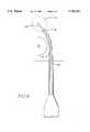
- FIG. 1is a planar view of a stylet ablation device of this invention.
- FIG. 2is a top view of the handle top plate of the stylet ablation device shown in FIG. 1.
- FIG. 3is a fragmentary cross-sectional view of the manual control portion of the handle of the stylet ablation device shown in FIG. 1, taken along the line A--A in FIG. 1.
- FIG. 4is a fragmentary cross-sectional view of the tip of the stylet ablation device such as that shown in FIG. 1 with the stylet retracted into the tip.
- FIG. 6is a schematic view showing use of an embodiment with a shape memory electrode preformed into a curved shape to treat a near zero access area behind an obstruction.
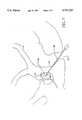
- FIG. 7is a schematic view showing use of a device of this invention for rectal ablation of the prostate.
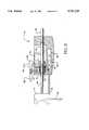
- FIG. 8is a prospective view of one embodiment of this invention having cut away parts to illustrate the construction thereof.
- FIG. 9is a partial cross-sectional view of the embodiment of FIG. 8 in which the stylet is spring-loaded in its retracted position.
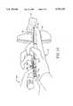
- FIG. 10is a view of the use of the embodiment of FIG. 8 in which the physician has guided the guide tube and stylet point to a desired location in a gland such as the prostate gland.
- the medical ablation devices of this inventionare uniquely superior for localized therapeutic ablation to remove or reduce undesired tissue masses from remote locations in the body.
- the devicescan be used with conventional delivery systems including scopes such as laparoscopes, cystoscopes, and the like.
- delivery tubessuch as needles
- the device with a memory shaped electrodecan be used to ablate undesired tissue in orthopedic, neurological, gynecological and for less invasive surgical applications such as near zero surgical ablation of spinal discs to alleviate encroachment and pressure from herniated disks on adjacent nerves in the spinal column.
- FIG. 1is a planar view of a stylet ablation device of this invention.
- the devicecomprises a handle portion 2 and a delivery tube portion 4.
- Stylet sleeve control manual tab 5 and stylet electrode control manual tab 8are mounted for sliding engagement in slots 10 and 12 in the handle top plate 14 (FIG. 2).
- Index markings 16indicate the relative angle of orientation of the stylet with respect to the stylet angle indicator 18.
- Angle indicator 18can be a bubble in a curved transparent tube, a weighted pivot dial indicator or an electronic angle indicator.
- the position of the distal edges 20 and 22 of the tab slides 5 and 8 with their respective gauge reference strips 24 and 26independently indicate the relative advancement and retraction of the stylet electrode and sleeve shown in FIGS. 2-4.
- Connectors for the fiber optic connector 23, RF power connector 25, and ohmic resistance detector 27extend from the proximal end of the handle housing.
- FIG. 2is a top view of the handle top plate of the stylet ablation device shown in FIG. 1.
- Slots 10 and 12receive the respective tabs 6 and 8 for sliding engagement therein.
- Slot 28receives the stylet angle indicator.
- FIG. 3is a fragmentary cross-sectional view of the manual control portion of the handle of the stylet ablation device shown in FIG. 1, taken along the line A--A.
- Manual electrode tab 6is attached to an electrode connector 30 which is connected to the proximal end of the stylet electrode 32.
- Manual sleeve table 8(FIG. 1) is connected to a sleeve connector 34 which is connected to the proximal end of the sleeve 36.
- the electrode 32is preferably made of a flexible, shape memory metal such as nickel-titanium allow or tempered steel.
- the sleeveis made of a highly conformable insulating plastic material such as polyamide.
- Simultaneous forward and rearward movement of the control tabs 6 and 8effect simultaneous advancement and retraction f the treatment stylet.
- Individual movement of the control tabs 6 and 8provide individual advancing and retracting movement of the respective sleeve and electrode.
- Indexing strips 24 and 26provide reference points for controlled positioning of the sleeve control tabs 6 and 8, permitting precise, independent positioning of the stylet elements for controlled ablation of remote body portions as is explained in greater detail hereinafter.
- FIG. 4is a cross-sectional view of the tip of the stylet ablation device such as that shown in FIG. 1 with the stylet retracted into the tip for initial insertion to a position accessible with a straight needle.
- the electrode tip 38is positioned behind the leading sharpened tip 40 of the needle or tube 42.
- the insulating sleeve tip 44is positioned just behind the leading edge of the electrode tip 38.
- the electrode 32When the electrode 32 is a hollow tube, it can be a conduit for aspiration during treatment, liquid delivery, or in the embodiment shown, a housing for a fiber optic 46.
- the polished fiber optic tip 48is then positioned behind the electrode tip 38 to facilitate viewing of the tissue surrounding the electrode tip during insertion.
- FIG. 5is a cross-sectional view of the tip of the stylet ablation device shown in FIG. 4 with the electrode and sleeve extended.
- This embodimentshows a flexible stylet 50 having a predetermined curved configuration.
- the flexible styletcan also be straight, if the remote position can be reached by a straight path from the point of entry without damaging a vital body component.
- the electrodecan be made of a shape memory alloy, shaped to revert to a desired configuration when released from the tubing.
- the configurationcan be simple curves, a combination of straight portions and curves, curves with differing radii, in two or three dimensions, selected to direct the electrode and its surrounding flexible, highly conformable sleeve in a preselected two or three dimensional path through tissue to a site to be ablated.
- Methods for shaping shape memory alloysare well known in the art and are not a part of this invention.
- the alloysare annealed with heat and then set in the desired memory shape by quick cooling the annealed electrode while maintaining it in the non-linear shape ultimately desired.
- the sleeve 36is initially in the dotted line position 52. Following insertion into the body to the specific site to be ablated, the sleeve 36 is withdrawn from a selected portion of the electrode 32 to the solid line position to expose the specific electrode area required to form a lesion of the desired size.
- a method of this invention for medical ablation of difficult to access tissuescomprising first inserting a hollow needle through a tissue layer, the needle enclosing a conductive electrode of highly flexible memory metal having a predetermined curved memory configuration and a sharpened distal terminus, the electrode tube being enclosed within an insulating sleeve axially moveable thereon and bendable therewith. Then the electrode and sleeve are advanced from the terminal end of the hollow needle, whereby the portion of the electrode and sleeve advanced beyond the end of the needle adopt the predetermined curved memory configuration and the electrode and sleeve follow a correspondingly predetermined curved path through tissue to the site to be ablated. Then a portion of the sleeve is withdrawn from the terminus of the electrode to expose a predetermined electrode area for ablation. Finally, RF energy is applied to the tissue surrounding the exposed electrode area to effect ablation thereof.
- FIG. 6use of an embodiment with a shape memory electrode preformed into a curved shape to ablate a near zero access area behind an obstruction in the body.
- the objective of the treatmentis to reduce the size of the mass 54 behind a rigid obstacle such as bone 56 (or area to be protected from penetration).
- the electrical conductor and sleeveis extended from the needle 40 through surrounding tissue around the obstacle to its back surface, and the target tissue to be reduced.
- the sleeve 36is then withdrawn to a position exposing the electrode area required to ablate the tissue mass. Heat is generated in the target tissue from an electric current or electromagnetic field produced by the electrical conductor.
- the volume of tissue being treatedis controlled by moving the non-conductive sleeve to expose a selected length of electrode in the body tissue to be treated, the remaining area of the electrode remaining shielded by the sleeve to protect the intervening tissues.
- the amount and duration of the energy deliveryis also varied to control the volume of tissue being treated.
- the currentpasses to a large surface area grounding plate contacting the outer skin surface.
- FIG. 7is a schematic view showing use of a device of this invention for rectal ablation of the prostate.
- the sharp tipped cannula 58is inserted into the rectum 60 and through the rectal surface 62 to the prostate 64.
- the stylet 66is extended to the area of the prostate to be ablated.
- the sleeve 68is then withdrawn, exposing the electrode 70, and RF power is applied to effect the ablation, the current passing from the electrode 70 through the surrounding tissue to a conventional surface electrode (not shown).
- FIG. 8is a prospective view of one transrectal embodiment of this invention having cut away parts to illustrate the construction thereof
- FIG. 9is a partial cross-section of the handle of the embodiment of FIG. 8 wherein the cutting cannula is spring-loaded in its retracted position.
- a handle 72formed from plastic, such as polystyrene, and designed for the needle to be disposable after use. Handle 72 preferably includes a curved bottom portion 74 which will fit comfortably in the physician's palm.
- a recess or slot 76is provided in the rear portion of handle 72 as well as a slot 76 adjacent the bottom surface 80.
- a guide tube 82is disposed in the forward end of handle 72 and is cemented or otherwise anchored therein.
- Guide tube 82may be of any suitable material, such as stainless steel, and may have a projecting length on the order of 11 to 16 cm and an outside diameter of about 2 mm.
- Slidably disposed within guide tube 82is cutting cannula 84 having a diameter of about 1.5 mm and an overall length of about 15 to 20 cm.
- the proximal end of cannula 84is provided with a thumb tab 86 attached thereto. Thumb tab 86 is configured to fit recess 76 and to be able to slide from the rear position shown to a forward position. The amount of movement will depend upon the distance to the tissue to be ablated.
- a stylet 88which may have a length of about 19 to 24 cm and a diameter of about 1 mm, is telescopically disposed within cannula 84 and is attached to control rod 90 extending through opening 92 in the rear wall end of body 72.
- a push knob 94is attached to the proximal end of control rod 90 and is moveable forward to contact the rear wall of body 72. A movement forward of about 2.5 cm is suitable.
- a stop bar 96 provided with a catch portion 98is connected to push knob 94. Stopbar 96 is shown in the full rearward position in which catch 98 has engaged tab 100 in recess 78.
- knob 94 and stopbar 96are formed from plastic which has sufficient flexibility to cause catch 98 to disengage when a slight forward pressure is placed on push knob 94.
- the distal end of cannula 94does not extend beyond the distal end of guide tube 82 while the tip of stylet 88 extends slightly beyond the distal end of guide tube 82.
- the cannula 84when in the retracted position, is spring-loaded by means of coil spring 102 in recess 104 at the rear portion of handle 78.
- Spring 102is maintained in the compressed condition by detent lever 106 working against coil spring 110.
- detent lever 106working against coil spring 110.
- the styletis connected to a source of RF energy by conventional connections, for example the power connector 103.
- FIG. 19is a view of the use of the embodiment of FIGS. 8 and 9 in which the physician has guided the guide tube and stylet point to a desired location in a gland such as the prostate gland.
- the physicianplaces the handle 72 in the right hand 111 with thumb tab 86 projecting outward.
- the tip of the index finger 112 iis placed at the distal end of guide tube 82 which is in the condition with stylet 88 and cannula 84 (FIG. 9) fully retracted.
- the physicianpermits the tip of style 88 to be forced against the fingertip.
- Using the right hand onlyhe inserts the index finger 112 and guide tube 82 into the patient's rectum and contacts the prostate gland 114 with the fingertip.
- the physicianmay the explore the surface of the gland to find a portion to be ablated. At that point, he may force the sharpened tip of the cannula 84 into the prostate. Next, the physician, using the left hand 116, depresses release tab 108, releasing the thumb tab 86 and projecting the stylet 88 into the prostate tissue.
Landscapes
- Health & Medical Sciences (AREA)
- Life Sciences & Earth Sciences (AREA)
- Surgery (AREA)
- Engineering & Computer Science (AREA)
- Biomedical Technology (AREA)
- Veterinary Medicine (AREA)
- Animal Behavior & Ethology (AREA)
- Nuclear Medicine, Radiotherapy & Molecular Imaging (AREA)
- Public Health (AREA)
- General Health & Medical Sciences (AREA)
- Heart & Thoracic Surgery (AREA)
- Molecular Biology (AREA)
- Medical Informatics (AREA)
- Otolaryngology (AREA)
- Physics & Mathematics (AREA)
- Electromagnetism (AREA)
- Radiology & Medical Imaging (AREA)
- Pathology (AREA)
- Plasma & Fusion (AREA)
- Surgical Instruments (AREA)
Abstract
Description
Claims (19)
Priority Applications (3)
| Application Number | Priority Date | Filing Date | Title |
|---|---|---|---|
| US08/589,111US5741225A (en) | 1992-08-12 | 1996-01-23 | Method for treating the prostate |
| AU15278/97AAU1527897A (en) | 1996-01-23 | 1997-01-07 | Method for treating the prostate |
| PCT/US1997/000177WO1997026836A1 (en) | 1996-01-23 | 1997-01-07 | Method for treating the prostate |
Applications Claiming Priority (7)
| Application Number | Priority Date | Filing Date | Title |
|---|---|---|---|
| US92963892A | 1992-08-12 | 1992-08-12 | |
| US08/012,370US5370675A (en) | 1992-08-12 | 1993-02-02 | Medical probe device and method |
| US08/061,647US5421819A (en) | 1992-08-12 | 1993-05-13 | Medical probe device |
| US08/062,364US5435805A (en) | 1992-08-12 | 1993-05-13 | Medical probe device with optical viewing capability |
| US08/061,072US5385544A (en) | 1992-08-12 | 1993-05-14 | BPH ablation method and apparatus |
| US08/148,441US5486161A (en) | 1993-02-02 | 1993-11-08 | Medical probe device and method |
| US08/589,111US5741225A (en) | 1992-08-12 | 1996-01-23 | Method for treating the prostate |
Related Parent Applications (1)
| Application Number | Title | Priority Date | Filing Date |
|---|---|---|---|
| US08/148,441Continuation-In-PartUS5486161A (en) | 1992-08-12 | 1993-11-08 | Medical probe device and method |
Publications (1)
| Publication Number | Publication Date |
|---|---|
| US5741225Atrue US5741225A (en) | 1998-04-21 |
Family
ID=24356638
Family Applications (1)
| Application Number | Title | Priority Date | Filing Date |
|---|---|---|---|
| US08/589,111Expired - LifetimeUS5741225A (en) | 1992-08-12 | 1996-01-23 | Method for treating the prostate |
Country Status (3)
| Country | Link |
|---|---|
| US (1) | US5741225A (en) |
| AU (1) | AU1527897A (en) |
| WO (1) | WO1997026836A1 (en) |
Cited By (84)
| Publication number | Priority date | Publication date | Assignee | Title |
|---|---|---|---|---|
| US5921954A (en) | 1996-07-10 | 1999-07-13 | Mohr, Jr.; Lawrence G. | Treating aneurysms by applying hardening/softening agents to hardenable/softenable substances |
| US6045549A (en)* | 1997-09-30 | 2000-04-04 | Somnus Medical Technologies, Inc. | Tissue ablation apparatus and device for use therein and method |
| WO2000061023A1 (en)* | 1999-04-08 | 2000-10-19 | Synergetics, Inc. | Directional laser probe |
| WO2001005317A1 (en)* | 1999-07-21 | 2001-01-25 | Thermo-Med 2000 Kft | Electrosurgical probe for tumor treatment by radiofrequency |
| US6261241B1 (en)* | 1998-03-03 | 2001-07-17 | Senorx, Inc. | Electrosurgical biopsy device and method |
| US6338726B1 (en) | 1997-02-06 | 2002-01-15 | Vidacare, Inc. | Treating urinary and other body strictures |
| US6405733B1 (en) | 2000-02-18 | 2002-06-18 | Thomas J. Fogarty | Device for accurately marking tissue |
| US20020173689A1 (en)* | 2001-04-24 | 2002-11-21 | Microspherix Llc | Deflectable implantation device and method of use |
| US20020193786A1 (en)* | 1998-10-23 | 2002-12-19 | Dany Berube | Directional microwave ablation instrument with off-set energy delivery portion |
| US6497706B1 (en) | 1998-03-03 | 2002-12-24 | Senorx, Inc. | Biopsy device and method of use |
| US6517498B1 (en) | 1998-03-03 | 2003-02-11 | Senorx, Inc. | Apparatus and method for tissue capture |
| US6540695B1 (en) | 1998-04-08 | 2003-04-01 | Senorx, Inc. | Biopsy anchor device with cutter |
| US20030065263A1 (en)* | 1999-10-05 | 2003-04-03 | Omnisonics Medical Technologies, Inc. | Ultrasonic probe device with rapid attachment and detachment means having a line contact collet |
| US6551337B1 (en) | 1999-10-05 | 2003-04-22 | Omnisonics Medical Technologies, Inc. | Ultrasonic medical device operating in a transverse mode |
| US20030088257A1 (en)* | 2001-11-06 | 2003-05-08 | Awh Carl C | Directional endo-illuminator |
| US20030093007A1 (en)* | 2001-10-17 | 2003-05-15 | The Government Of The U.S.A., As Represented By The Secretary, Department Of Health And Human Serv | Biopsy apparatus with radio frequency cauterization and methods for its use |
| US6607528B1 (en)* | 1999-06-22 | 2003-08-19 | Senorx, Inc. | Shapeable electrosurgical scalpel |
| US20030163128A1 (en)* | 2000-12-29 | 2003-08-28 | Afx, Inc. | Tissue ablation system with a sliding ablating device and method |
| US20030191461A1 (en)* | 2000-04-07 | 2003-10-09 | Synergetics, Inc., A Corporation | Directional laser probe |
| US20030195499A1 (en)* | 2002-04-16 | 2003-10-16 | Mani Prakash | Microwave antenna having a curved configuration |
| US20030195500A1 (en)* | 1999-06-17 | 2003-10-16 | Moorman Jack W. | Needle kit and method for microwave ablation, track coagulation, and biopsy |
| US6638234B2 (en) | 1998-03-03 | 2003-10-28 | Senorx, Inc. | Sentinel node location and biopsy |
| US6638277B2 (en) | 2000-07-06 | 2003-10-28 | Scimed Life Systems, Inc. | Tumor ablation needle with independently activated and independently traversing tines |
| US6660013B2 (en) | 1999-10-05 | 2003-12-09 | Omnisonics Medical Technologies, Inc. | Apparatus for removing plaque from blood vessels using ultrasonic energy |
| US6659105B2 (en) | 1998-02-26 | 2003-12-09 | Senorx, Inc. | Tissue specimen isolating and damaging device and method |
| US20030236539A1 (en)* | 1999-10-05 | 2003-12-25 | Omnisonics Medical Technologies, Inc. | Apparatus and method for using an ultrasonic probe to clear a vascular access device |
| EP1186274A3 (en)* | 2000-09-12 | 2004-01-14 | AFX, Inc. | Surgical microwave ablation assembly |
| US6679851B2 (en) | 1998-09-01 | 2004-01-20 | Senorx, Inc. | Tissue accessing and anchoring device and method |
| US6695782B2 (en) | 1999-10-05 | 2004-02-24 | Omnisonics Medical Technologies, Inc. | Ultrasonic probe device with rapid attachment and detachment means |
| US20040055118A1 (en)* | 2002-09-20 | 2004-03-25 | Marty Justin Douglas | Multi-track fastening system |
| US6722371B1 (en) | 2000-02-18 | 2004-04-20 | Thomas J. Fogarty | Device for accurately marking tissue |
| US6733451B2 (en) | 1999-10-05 | 2004-05-11 | Omnisonics Medical Technologies, Inc. | Apparatus and method for an ultrasonic probe used with a pharmacological agent |
| US20040097996A1 (en)* | 1999-10-05 | 2004-05-20 | Omnisonics Medical Technologies, Inc. | Apparatus and method of removing occlusions using an ultrasonic medical device operating in a transverse mode |
| US20040106937A1 (en)* | 2002-06-21 | 2004-06-03 | Afx, Inc. | Clamp accessory and method for an ablation instrument |
| US6752767B2 (en) | 2002-04-16 | 2004-06-22 | Vivant Medical, Inc. | Localization element with energized tip |
| US6752154B2 (en) | 2000-02-18 | 2004-06-22 | Thomas J. Fogarty | Device for accurately marking tissue |
| US6758848B2 (en) | 1998-03-03 | 2004-07-06 | Senorx, Inc. | Apparatus and method for accessing a body site |
| US20040158150A1 (en)* | 1999-10-05 | 2004-08-12 | Omnisonics Medical Technologies, Inc. | Apparatus and method for an ultrasonic medical device for tissue remodeling |
| US20040249401A1 (en)* | 1999-10-05 | 2004-12-09 | Omnisonics Medical Technologies, Inc. | Apparatus and method for an ultrasonic medical device with a non-compliant balloon |
| US20050015081A1 (en)* | 2003-07-18 | 2005-01-20 | Roman Turovskiy | Devices and methods for cooling microwave antennas |
| US20050038462A1 (en)* | 1998-04-08 | 2005-02-17 | Senorx, Inc. | Dilation devices and methods for removing tissue specimens |
| US20050043629A1 (en)* | 1999-10-05 | 2005-02-24 | Omnisonics Medical Technologies, Inc. | Apparatus and method for an ultrasonic medical device having a probe with a small proximal end |
| US20050043753A1 (en)* | 1999-10-05 | 2005-02-24 | Omnisonics Medical Technologies, Inc. | Apparatus and method for an ultrasonic medical device to treat peripheral artery disease |
| US6875182B2 (en) | 1998-03-03 | 2005-04-05 | Senorx, Inc. | Electrosurgical specimen-collection system |
| US20050096669A1 (en)* | 1999-10-05 | 2005-05-05 | Omnisonics Medical Technologies, Inc. | Apparatus and method for an ultrasonic medical device to treat coronary thrombus bearing lesions |
| US20050119679A1 (en)* | 1999-10-05 | 2005-06-02 | Omnisonics Medical Technologies, Inc. | Apparatus and method for an ultrasonic medical device to treat chronic total occlusions |
| US20050154379A1 (en)* | 2003-01-31 | 2005-07-14 | Innovatech Surgical, Inc. | Adjustable laser probe for use in vitreoretinal surgery |
| US20050234450A1 (en)* | 2004-04-15 | 2005-10-20 | Barker B T | Transfer ring for offset tapered 3D connector |
| US20050267553A1 (en)* | 2004-05-05 | 2005-12-01 | Doug Staunton | System and method for controlling electrical stimulation and radiofrequency output for use in an electrosurgical procedure |
| US6976986B2 (en) | 2000-04-12 | 2005-12-20 | Afx, Inc. | Electrode arrangement for use in a medical instrument |
| US20060058780A1 (en)* | 1996-05-06 | 2006-03-16 | Edwards Stuart D | Treatment of tissue in sphincters, sinuses, and orifices |
| US7033352B1 (en) | 2000-01-18 | 2006-04-25 | Afx, Inc. | Flexible ablation instrument |
| US7099717B2 (en) | 2002-01-03 | 2006-08-29 | Afx Inc. | Catheter having improved steering |
| US20060217790A1 (en)* | 2005-03-28 | 2006-09-28 | Ohshin Mlp Co., Ltd. | Sheet-like face pack and kits for face packs |
| US20070038146A1 (en)* | 2005-08-05 | 2007-02-15 | Quick Richard L | Biopsy device with fluid delivery to tissue specimens |
| US7192427B2 (en) | 2002-02-19 | 2007-03-20 | Afx, Inc. | Apparatus and method for assessing transmurality of a tissue ablation |
| US20070191823A1 (en)* | 2003-11-13 | 2007-08-16 | Synergetics, Inc. | Illuminated laser probe with adjustable area of illumination |
| US7303560B2 (en) | 2000-12-29 | 2007-12-04 | Afx, Inc. | Method of positioning a medical instrument |
| US7318824B2 (en) | 2001-11-02 | 2008-01-15 | Vivant Medical, Inc. | High-strength microwave antenna assemblies |
| WO2008014144A2 (en) | 2006-07-24 | 2008-01-31 | Ethicon, Inc. | Articulating laparoscopic device and method for delivery of medical fluid |
| US7346399B2 (en) | 1999-05-28 | 2008-03-18 | Afx, Inc. | Monopole tip for ablation catheter |
| US20080082093A1 (en)* | 2006-09-29 | 2008-04-03 | Prakash Mani N | Microwave antenna assembly and method of using the same |
| US20080287938A1 (en)* | 2005-08-11 | 2008-11-20 | Synergetics, Inc. | Illuminated Directional Laser Probe |
| US7503895B2 (en) | 1999-10-05 | 2009-03-17 | Omnisonics Medical Technologies, Inc. | Ultrasonic device for tissue ablation and sheath for use therewith |
| US20090112118A1 (en)* | 2005-08-05 | 2009-04-30 | Senorx, Inc. | Biopsy device with fluid delivery to tissue specimens |
| US20090187222A1 (en)* | 2008-01-23 | 2009-07-23 | Boston Scientific Neuromodulation Corporation | Steerable stylet handle assembly |
| US20090204021A1 (en)* | 2004-12-16 | 2009-08-13 | Senorx, Inc. | Apparatus and method for accessing a body site |
| US7794414B2 (en) | 2004-02-09 | 2010-09-14 | Emigrant Bank, N.A. | Apparatus and method for an ultrasonic medical device operating in torsional and transverse modes |
| US20110196356A1 (en)* | 2009-09-15 | 2011-08-11 | Ceramoptec Industries Inc. | Ablative/coagulative urological treatment device and method |
| US8292880B2 (en) | 2007-11-27 | 2012-10-23 | Vivant Medical, Inc. | Targeted cooling of deployable microwave antenna |
| US8343071B2 (en) | 2004-12-16 | 2013-01-01 | Senorx, Inc. | Biopsy device with aperture orientation and improved tip |
| US8353908B2 (en) | 1996-09-20 | 2013-01-15 | Novasys Medical, Inc. | Treatment of tissue in sphincters, sinuses, and orifices |
| US8403927B1 (en) | 2012-04-05 | 2013-03-26 | William Bruce Shingleton | Vasectomy devices and methods |
| US20130090531A1 (en)* | 2011-09-27 | 2013-04-11 | Edwin Ryan | Small gauge surgical instrument with adjustable support |
| US8641640B2 (en) | 2005-05-23 | 2014-02-04 | Senorx, Inc. | Tissue cutting member for a biopsy device |
| US8968284B2 (en) | 2000-10-02 | 2015-03-03 | Verathon Inc. | Apparatus and methods for treating female urinary incontinence |
| US9023031B2 (en) | 1997-08-13 | 2015-05-05 | Verathon Inc. | Noninvasive devices, methods, and systems for modifying tissues |
| US9216012B2 (en) | 1998-09-01 | 2015-12-22 | Senorx, Inc | Methods and apparatus for securing medical instruments to desired locations in a patient's body |
| US9335455B2 (en) | 2012-05-30 | 2016-05-10 | Cygnus, LP | Extended tip laser and illumination probe for retina surgery |
| US9370447B2 (en)* | 2011-10-10 | 2016-06-21 | Cygnus LP | Probes for use in ophthalmic and vitreoretinal surgery |
| US9408592B2 (en) | 2003-12-23 | 2016-08-09 | Senorx, Inc. | Biopsy device with aperture orientation and improved tip |
| US20170050014A1 (en)* | 2015-04-07 | 2017-02-23 | Alpha Omega Neuro Technologies Ltd. | Reduced larsen effect electrode |
| US10022200B2 (en) | 2014-08-25 | 2018-07-17 | Peregrine Surgical, Ltd | Microsurgical instrument |
| US20210282868A1 (en)* | 2014-09-05 | 2021-09-16 | Procept Biorobotics Corporation | Elongate treatment probe with encoder for robotics surgery |
Families Citing this family (3)
| Publication number | Priority date | Publication date | Assignee | Title |
|---|---|---|---|---|
| US6096036A (en)* | 1998-05-05 | 2000-08-01 | Cardiac Pacemakers, Inc. | Steerable catheter with preformed distal shape and method for use |
| US6146381A (en)* | 1998-05-05 | 2000-11-14 | Cardiac Pacemakers, Inc. | Catheter having distal region for deflecting axial forces |
| US7643884B2 (en)* | 2005-01-31 | 2010-01-05 | Warsaw Orthopedic, Inc. | Electrically insulated surgical needle assembly |
Citations (1)
| Publication number | Priority date | Publication date | Assignee | Title |
|---|---|---|---|---|
| US5421819A (en)* | 1992-08-12 | 1995-06-06 | Vidamed, Inc. | Medical probe device |
Family Cites Families (2)
| Publication number | Priority date | Publication date | Assignee | Title |
|---|---|---|---|---|
| US5486161A (en)* | 1993-02-02 | 1996-01-23 | Zomed International | Medical probe device and method |
| IL108532A (en)* | 1993-02-02 | 1997-07-13 | Vidamed Inc | Transurethral needle ablation device |
- 1996
- 1996-01-23USUS08/589,111patent/US5741225A/ennot_activeExpired - Lifetime
- 1997
- 1997-01-07AUAU15278/97Apatent/AU1527897A/ennot_activeAbandoned
- 1997-01-07WOPCT/US1997/000177patent/WO1997026836A1/enactiveApplication Filing
Patent Citations (1)
| Publication number | Priority date | Publication date | Assignee | Title |
|---|---|---|---|---|
| US5421819A (en)* | 1992-08-12 | 1995-06-06 | Vidamed, Inc. | Medical probe device |
Cited By (185)
| Publication number | Priority date | Publication date | Assignee | Title |
|---|---|---|---|---|
| US8412318B2 (en) | 1996-05-06 | 2013-04-02 | Novasys Medical, Inc. | Treatment of tissue in sphincters, sinuses, and orifices |
| US20060058780A1 (en)* | 1996-05-06 | 2006-03-16 | Edwards Stuart D | Treatment of tissue in sphincters, sinuses, and orifices |
| US5921954A (en) | 1996-07-10 | 1999-07-13 | Mohr, Jr.; Lawrence G. | Treating aneurysms by applying hardening/softening agents to hardenable/softenable substances |
| US8740846B2 (en) | 1996-09-20 | 2014-06-03 | Verathon, Inc. | Treatment of tissue in sphincters, sinuses, and orifices |
| US8353908B2 (en) | 1996-09-20 | 2013-01-15 | Novasys Medical, Inc. | Treatment of tissue in sphincters, sinuses, and orifices |
| US6338726B1 (en) | 1997-02-06 | 2002-01-15 | Vidacare, Inc. | Treating urinary and other body strictures |
| US9023031B2 (en) | 1997-08-13 | 2015-05-05 | Verathon Inc. | Noninvasive devices, methods, and systems for modifying tissues |
| US6045549A (en)* | 1997-09-30 | 2000-04-04 | Somnus Medical Technologies, Inc. | Tissue ablation apparatus and device for use therein and method |
| US6659105B2 (en) | 1998-02-26 | 2003-12-09 | Senorx, Inc. | Tissue specimen isolating and damaging device and method |
| US8147487B2 (en) | 1998-03-03 | 2012-04-03 | Senorx, Inc. | Apparatus and method for accessing a body site |
| US6517498B1 (en) | 1998-03-03 | 2003-02-11 | Senorx, Inc. | Apparatus and method for tissue capture |
| US7625347B2 (en) | 1998-03-03 | 2009-12-01 | Senorx, Inc. | Electrosurgical biopsy device and method |
| US6716179B2 (en) | 1998-03-03 | 2004-04-06 | Senorx, Inc. | Sentinel node location and biopsy |
| US6758848B2 (en) | 1998-03-03 | 2004-07-06 | Senorx, Inc. | Apparatus and method for accessing a body site |
| US6689071B2 (en) | 1998-03-03 | 2004-02-10 | Senorx, Inc. | Electrosurgical biopsy device and method |
| US6638234B2 (en) | 1998-03-03 | 2003-10-28 | Senorx, Inc. | Sentinel node location and biopsy |
| US6261241B1 (en)* | 1998-03-03 | 2001-07-17 | Senorx, Inc. | Electrosurgical biopsy device and method |
| US7229439B2 (en) | 1998-03-03 | 2007-06-12 | Senorx, Inc. | Apparatus and method for accessing a body site |
| US6497706B1 (en) | 1998-03-03 | 2002-12-24 | Senorx, Inc. | Biopsy device and method of use |
| US6875182B2 (en) | 1998-03-03 | 2005-04-05 | Senorx, Inc. | Electrosurgical specimen-collection system |
| US20050090762A1 (en)* | 1998-03-03 | 2005-04-28 | Senorx, Inc. | Electrosurgical biopsy device and method |
| US20070232955A1 (en)* | 1998-03-03 | 2007-10-04 | Senorx, Inc. | Apparatus and method for accessing a body site |
| US7357801B2 (en) | 1998-04-08 | 2008-04-15 | Senorx, Inc. | Tissue specimen isolating and damaging device and method |
| US7377902B2 (en) | 1998-04-08 | 2008-05-27 | Senorx, Inc. | Biopsy anchor device with cutter |
| US20080287828A1 (en)* | 1998-04-08 | 2008-11-20 | Fred Burbank | Biopsy anchor device with cutter |
| US20050038462A1 (en)* | 1998-04-08 | 2005-02-17 | Senorx, Inc. | Dilation devices and methods for removing tissue specimens |
| US20040204709A1 (en)* | 1998-04-08 | 2004-10-14 | Senorx, Inc. | Tissue specimen isolating and damaging device and method |
| US6997885B2 (en) | 1998-04-08 | 2006-02-14 | Senorx, Inc. | Dilation devices and methods for removing tissue specimens |
| US7651467B2 (en) | 1998-04-08 | 2010-01-26 | Senorx, Inc | Dilation devices and methods for removing tissue specimens |
| US20030144605A1 (en)* | 1998-04-08 | 2003-07-31 | Senorx, Inc. | Biopsy anchor device with cutter |
| US6540695B1 (en) | 1998-04-08 | 2003-04-01 | Senorx, Inc. | Biopsy anchor device with cutter |
| US6676658B2 (en) | 1998-04-08 | 2004-01-13 | Senorx, Inc. | Tissue specimen isolating and damaging device and method |
| US9216012B2 (en) | 1998-09-01 | 2015-12-22 | Senorx, Inc | Methods and apparatus for securing medical instruments to desired locations in a patient's body |
| US6679851B2 (en) | 1998-09-01 | 2004-01-20 | Senorx, Inc. | Tissue accessing and anchoring device and method |
| US20050197594A1 (en)* | 1998-09-01 | 2005-09-08 | Senorx, Inc. | Tissue accessing and anchoring device and method |
| US7282034B2 (en) | 1998-09-01 | 2007-10-16 | Senorx, Inc. | Tissue accessing and anchoring device and method |
| US20040117652A1 (en)* | 1998-09-01 | 2004-06-17 | Senorx, Inc. | Tissue accessing and anchoring device and method |
| US7052491B2 (en) | 1998-10-23 | 2006-05-30 | Afx, Inc. | Vacuum-assisted securing apparatus for a microwave ablation instrument |
| US20020193786A1 (en)* | 1998-10-23 | 2002-12-19 | Dany Berube | Directional microwave ablation instrument with off-set energy delivery portion |
| US7115126B2 (en) | 1998-10-23 | 2006-10-03 | Afx Inc. | Directional microwave ablation instrument with off-set energy delivery portion |
| US7387627B2 (en) | 1998-10-23 | 2008-06-17 | Maquet Cardiovascular Llc | Vacuum-assisted securing apparatus for a microwave ablation instrument |
| US9510809B2 (en) | 1999-01-27 | 2016-12-06 | Senorx, Inc. | Tissue specimen isolating and damaging device and method |
| US8636734B2 (en) | 1999-01-27 | 2014-01-28 | Senorx, Inc. | Tissue specimen isolating and damaging device and method |
| EP1083839B2 (en)† | 1999-04-08 | 2015-11-04 | Synergetics, Inc. | Directional laser probe |
| WO2000061023A1 (en)* | 1999-04-08 | 2000-10-19 | Synergetics, Inc. | Directional laser probe |
| US20070203480A1 (en)* | 1999-05-04 | 2007-08-30 | Dinesh Mody | Surgical microwave ablation assembly |
| US7226446B1 (en) | 1999-05-04 | 2007-06-05 | Dinesh Mody | Surgical microwave ablation assembly |
| US7346399B2 (en) | 1999-05-28 | 2008-03-18 | Afx, Inc. | Monopole tip for ablation catheter |
| US7160292B2 (en) | 1999-06-17 | 2007-01-09 | Vivant Medical, Inc. | Needle kit and method for microwave ablation, track coagulation, and biopsy |
| US20070161977A1 (en)* | 1999-06-17 | 2007-07-12 | Moorman Jack W | Needle kit and method for microwave ablation, track coagulation, and biopsy |
| US8690868B2 (en) | 1999-06-17 | 2014-04-08 | Covidien Lp | Needle kit and method for microwave ablation, track coagulation, and biopsy |
| US20030195500A1 (en)* | 1999-06-17 | 2003-10-16 | Moorman Jack W. | Needle kit and method for microwave ablation, track coagulation, and biopsy |
| US6607528B1 (en)* | 1999-06-22 | 2003-08-19 | Senorx, Inc. | Shapeable electrosurgical scalpel |
| US7449022B2 (en) | 1999-06-22 | 2008-11-11 | Senorx, Inc. | Shapeable electrosurgical scalpel |
| US20040030334A1 (en)* | 1999-06-22 | 2004-02-12 | Senorx, Inc. | Shapeable electrosurgical scalpel |
| US20090082763A1 (en)* | 1999-06-22 | 2009-03-26 | Senorx,Inc. | Shapeable electrosurgical scalpel |
| WO2001005317A1 (en)* | 1999-07-21 | 2001-01-25 | Thermo-Med 2000 Kft | Electrosurgical probe for tumor treatment by radiofrequency |
| US6623481B1 (en) | 1999-07-21 | 2003-09-23 | Thermo-Med 2000 Kft | Electrosurgical probe for tumor treatment by radiofrequency |
| AU768134B2 (en)* | 1999-07-21 | 2003-12-04 | Invatec S.R.L. | Electrosurgical probe for tumor treatment by radiofrequency |
| US6733451B2 (en) | 1999-10-05 | 2004-05-11 | Omnisonics Medical Technologies, Inc. | Apparatus and method for an ultrasonic probe used with a pharmacological agent |
| US20050043629A1 (en)* | 1999-10-05 | 2005-02-24 | Omnisonics Medical Technologies, Inc. | Apparatus and method for an ultrasonic medical device having a probe with a small proximal end |
| US20040158150A1 (en)* | 1999-10-05 | 2004-08-12 | Omnisonics Medical Technologies, Inc. | Apparatus and method for an ultrasonic medical device for tissue remodeling |
| US20050096669A1 (en)* | 1999-10-05 | 2005-05-05 | Omnisonics Medical Technologies, Inc. | Apparatus and method for an ultrasonic medical device to treat coronary thrombus bearing lesions |
| US20050119679A1 (en)* | 1999-10-05 | 2005-06-02 | Omnisonics Medical Technologies, Inc. | Apparatus and method for an ultrasonic medical device to treat chronic total occlusions |
| US6866670B2 (en) | 1999-10-05 | 2005-03-15 | Omnisonics Medical Technologies, Inc. | Apparatus for removing plaque from blood vessels using ultrasonic energy |
| US20050043753A1 (en)* | 1999-10-05 | 2005-02-24 | Omnisonics Medical Technologies, Inc. | Apparatus and method for an ultrasonic medical device to treat peripheral artery disease |
| US20040097996A1 (en)* | 1999-10-05 | 2004-05-20 | Omnisonics Medical Technologies, Inc. | Apparatus and method of removing occlusions using an ultrasonic medical device operating in a transverse mode |
| US20040249401A1 (en)* | 1999-10-05 | 2004-12-09 | Omnisonics Medical Technologies, Inc. | Apparatus and method for an ultrasonic medical device with a non-compliant balloon |
| US20040073244A1 (en)* | 1999-10-05 | 2004-04-15 | Omnisonics Medical Technologies, Inc. | Method and apparatus for removing plaque from blood vessels using ultrasonic energy |
| US6695782B2 (en) | 1999-10-05 | 2004-02-24 | Omnisonics Medical Technologies, Inc. | Ultrasonic probe device with rapid attachment and detachment means |
| US20040158151A1 (en)* | 1999-10-05 | 2004-08-12 | Omnisonics Medical Technologies, Inc. | Apparatus and method for an ultrasonic probe device with rapid attachment and detachment means |
| US20030236539A1 (en)* | 1999-10-05 | 2003-12-25 | Omnisonics Medical Technologies, Inc. | Apparatus and method for using an ultrasonic probe to clear a vascular access device |
| US7494468B2 (en) | 1999-10-05 | 2009-02-24 | Omnisonics Medical Technologies, Inc. | Ultrasonic medical device operating in a transverse mode |
| US20030065263A1 (en)* | 1999-10-05 | 2003-04-03 | Omnisonics Medical Technologies, Inc. | Ultrasonic probe device with rapid attachment and detachment means having a line contact collet |
| US6660013B2 (en) | 1999-10-05 | 2003-12-09 | Omnisonics Medical Technologies, Inc. | Apparatus for removing plaque from blood vessels using ultrasonic energy |
| US20040162571A1 (en)* | 1999-10-05 | 2004-08-19 | Omnisonics Medical Technologies, Inc. | Apparatus and method for an ultrasonic medical device to treat deep vein thrombosis |
| US7503895B2 (en) | 1999-10-05 | 2009-03-17 | Omnisonics Medical Technologies, Inc. | Ultrasonic device for tissue ablation and sheath for use therewith |
| US20030125645A1 (en)* | 1999-10-05 | 2003-07-03 | Omnisonics Medical Technologies, Inc. | Ultrasonic medical device operating in a transverse mode |
| US8790359B2 (en) | 1999-10-05 | 2014-07-29 | Cybersonics, Inc. | Medical systems and related methods |
| US6551337B1 (en) | 1999-10-05 | 2003-04-22 | Omnisonics Medical Technologies, Inc. | Ultrasonic medical device operating in a transverse mode |
| US7033352B1 (en) | 2000-01-18 | 2006-04-25 | Afx, Inc. | Flexible ablation instrument |
| US7301131B2 (en) | 2000-01-18 | 2007-11-27 | Afx, Inc. | Microwave ablation instrument with flexible antenna assembly and method |
| US6752154B2 (en) | 2000-02-18 | 2004-06-22 | Thomas J. Fogarty | Device for accurately marking tissue |
| US7322360B2 (en) | 2000-02-18 | 2008-01-29 | Thomas J. Fogarty | Device for accurately marking tissue |
| US20040168692A1 (en)* | 2000-02-18 | 2004-09-02 | Thomas Fogarty | Device for accurately marking tissue |
| US6405733B1 (en) | 2000-02-18 | 2002-06-18 | Thomas J. Fogarty | Device for accurately marking tissue |
| US6564806B1 (en) | 2000-02-18 | 2003-05-20 | Thomas J. Fogarty | Device for accurately marking tissue |
| US6722371B1 (en) | 2000-02-18 | 2004-04-20 | Thomas J. Fogarty | Device for accurately marking tissue |
| US7473249B2 (en) | 2000-04-07 | 2009-01-06 | Synergetics, Inc. | Directional laser probe |
| US7402158B2 (en) | 2000-04-07 | 2008-07-22 | Synergetics, Inc. | Directional laser probe |
| US20030191461A1 (en)* | 2000-04-07 | 2003-10-09 | Synergetics, Inc., A Corporation | Directional laser probe |
| US20060173448A1 (en)* | 2000-04-07 | 2006-08-03 | Scheller Gregg D | Directional laser probe |
| US6984230B2 (en) | 2000-04-07 | 2006-01-10 | Synergetics, Inc. | Directional laser probe |
| US7156841B2 (en) | 2000-04-12 | 2007-01-02 | Afx, Inc. | Electrode arrangement for use in a medical instrument |
| US6976986B2 (en) | 2000-04-12 | 2005-12-20 | Afx, Inc. | Electrode arrangement for use in a medical instrument |
| US7025767B2 (en) | 2000-07-06 | 2006-04-11 | Boston Scientific Scimed, Inc. | Tumor ablation needle with independently activated and independently traversing tines |
| US6638277B2 (en) | 2000-07-06 | 2003-10-28 | Scimed Life Systems, Inc. | Tumor ablation needle with independently activated and independently traversing tines |
| EP1186274A3 (en)* | 2000-09-12 | 2004-01-14 | AFX, Inc. | Surgical microwave ablation assembly |
| US8968284B2 (en) | 2000-10-02 | 2015-03-03 | Verathon Inc. | Apparatus and methods for treating female urinary incontinence |
| US20030163128A1 (en)* | 2000-12-29 | 2003-08-28 | Afx, Inc. | Tissue ablation system with a sliding ablating device and method |
| US7303560B2 (en) | 2000-12-29 | 2007-12-04 | Afx, Inc. | Method of positioning a medical instrument |
| US7282020B2 (en)* | 2001-04-24 | 2007-10-16 | Microspherix Llc | Deflectable implantation device and method of use |
| US20080091056A1 (en)* | 2001-04-24 | 2008-04-17 | Microspherix Llc | Deflectable implantation device and method for use |
| US7922645B2 (en)* | 2001-04-24 | 2011-04-12 | Microspherix Llc | Deflectable implantation device and method for use |
| US20020173689A1 (en)* | 2001-04-24 | 2002-11-21 | Microspherix Llc | Deflectable implantation device and method of use |
| US20030093007A1 (en)* | 2001-10-17 | 2003-05-15 | The Government Of The U.S.A., As Represented By The Secretary, Department Of Health And Human Serv | Biopsy apparatus with radio frequency cauterization and methods for its use |
| US10154880B2 (en) | 2001-11-02 | 2018-12-18 | Covidien Lp | High-strength microwave antenna assemblies |
| US7318824B2 (en) | 2001-11-02 | 2008-01-15 | Vivant Medical, Inc. | High-strength microwave antenna assemblies |
| US20030088257A1 (en)* | 2001-11-06 | 2003-05-08 | Awh Carl C | Directional endo-illuminator |
| US7099717B2 (en) | 2002-01-03 | 2006-08-29 | Afx Inc. | Catheter having improved steering |
| US7192427B2 (en) | 2002-02-19 | 2007-03-20 | Afx, Inc. | Apparatus and method for assessing transmurality of a tissue ablation |
| US7468042B2 (en) | 2002-04-16 | 2008-12-23 | Vivant Medical, Inc. | Localization element with energized tip |
| US6752767B2 (en) | 2002-04-16 | 2004-06-22 | Vivant Medical, Inc. | Localization element with energized tip |
| US10039602B2 (en) | 2002-04-16 | 2018-08-07 | Covidien Lp | Electrosurgical energy channel splitters and systems for delivering electrosurgical energy |
| US20040267156A1 (en)* | 2002-04-16 | 2004-12-30 | Vivant Medical, Inc. | Localization element with energized tip |
| US11045253B2 (en) | 2002-04-16 | 2021-06-29 | Covidien Lp | Electrosurgical energy channel splitters and systems for delivering electrosurgical energy |
| US20070198006A1 (en)* | 2002-04-16 | 2007-08-23 | Mani Prakash | Microwave antenna having a curved configuration |
| US20030195499A1 (en)* | 2002-04-16 | 2003-10-16 | Mani Prakash | Microwave antenna having a curved configuration |
| US20090149850A1 (en)* | 2002-04-16 | 2009-06-11 | Vivant Medical, Inc. | Localization Element with Energized Tip |
| US10143520B2 (en) | 2002-04-16 | 2018-12-04 | Covidien Lp | Microwave antenna guide assembly |
| US10363097B2 (en) | 2002-04-16 | 2019-07-30 | Coviden Lp | Ablation system having multiple energy sources |
| US7197363B2 (en) | 2002-04-16 | 2007-03-27 | Vivant Medical, Inc. | Microwave antenna having a curved configuration |
| US8808282B2 (en) | 2002-04-16 | 2014-08-19 | Covidien Lp | Microwave antenna having a curved configuration |
| US7846108B2 (en) | 2002-04-16 | 2010-12-07 | Vivant Medical, Inc. | Localization element with energized tip |
| US20040106937A1 (en)* | 2002-06-21 | 2004-06-03 | Afx, Inc. | Clamp accessory and method for an ablation instrument |
| US20040055118A1 (en)* | 2002-09-20 | 2004-03-25 | Marty Justin Douglas | Multi-track fastening system |
| US20050154379A1 (en)* | 2003-01-31 | 2005-07-14 | Innovatech Surgical, Inc. | Adjustable laser probe for use in vitreoretinal surgery |
| US7766904B2 (en) | 2003-01-31 | 2010-08-03 | Iridex Corporation | Adjustable laser probe for use in vitreoretinal surgery |
| US7311703B2 (en) | 2003-07-18 | 2007-12-25 | Vivant Medical, Inc. | Devices and methods for cooling microwave antennas |
| US20050015081A1 (en)* | 2003-07-18 | 2005-01-20 | Roman Turovskiy | Devices and methods for cooling microwave antennas |
| US10405921B2 (en) | 2003-07-18 | 2019-09-10 | Covidien Lp | Devices and methods for cooling microwave antennas |
| US20070191823A1 (en)* | 2003-11-13 | 2007-08-16 | Synergetics, Inc. | Illuminated laser probe with adjustable area of illumination |
| US7972326B2 (en) | 2003-11-13 | 2011-07-05 | Synergetics, Inc. | Illuminated laser probe with adjustable area of illumination |
| US9408592B2 (en) | 2003-12-23 | 2016-08-09 | Senorx, Inc. | Biopsy device with aperture orientation and improved tip |
| US7794414B2 (en) | 2004-02-09 | 2010-09-14 | Emigrant Bank, N.A. | Apparatus and method for an ultrasonic medical device operating in torsional and transverse modes |
| US7377922B2 (en)* | 2004-04-15 | 2008-05-27 | Warsaw Orthopedic, Inc. | Transfer ring for offset tapered 3D connector |
| US20050234450A1 (en)* | 2004-04-15 | 2005-10-20 | Barker B T | Transfer ring for offset tapered 3D connector |
| US20050267553A1 (en)* | 2004-05-05 | 2005-12-01 | Doug Staunton | System and method for controlling electrical stimulation and radiofrequency output for use in an electrosurgical procedure |
| US20090204021A1 (en)* | 2004-12-16 | 2009-08-13 | Senorx, Inc. | Apparatus and method for accessing a body site |
| US8343071B2 (en) | 2004-12-16 | 2013-01-01 | Senorx, Inc. | Biopsy device with aperture orientation and improved tip |
| US11246574B2 (en) | 2004-12-16 | 2022-02-15 | Senorx, Inc. | Biopsy device with aperture orientation and improved tip |
| US8360990B2 (en) | 2004-12-16 | 2013-01-29 | Senorx, Inc. | Biopsy device with aperture orientation and improved tip |
| US10105125B2 (en) | 2004-12-16 | 2018-10-23 | Senorx, Inc. | Biopsy device with aperture orientation and improved tip |
| US20060217790A1 (en)* | 2005-03-28 | 2006-09-28 | Ohshin Mlp Co., Ltd. | Sheet-like face pack and kits for face packs |
| US9095325B2 (en) | 2005-05-23 | 2015-08-04 | Senorx, Inc. | Tissue cutting member for a biopsy device |
| US8641640B2 (en) | 2005-05-23 | 2014-02-04 | Senorx, Inc. | Tissue cutting member for a biopsy device |
| US10478161B2 (en) | 2005-05-23 | 2019-11-19 | Senorx, Inc. | Tissue cutting member for a biopsy device |
| US11426149B2 (en) | 2005-05-23 | 2022-08-30 | SenoRx., Inc. | Tissue cutting member for a biopsy device |
| US9750487B2 (en) | 2005-05-23 | 2017-09-05 | Senorx, Inc. | Tissue cutting member for a biopsy device |
| US20070038146A1 (en)* | 2005-08-05 | 2007-02-15 | Quick Richard L | Biopsy device with fluid delivery to tissue specimens |
| US7981051B2 (en) | 2005-08-05 | 2011-07-19 | Senorx, Inc. | Biopsy device with fluid delivery to tissue specimens |
| US8915864B2 (en) | 2005-08-05 | 2014-12-23 | Senorx, Inc. | Biopsy device with fluid delivery to tissue specimens |
| US10064609B2 (en) | 2005-08-05 | 2018-09-04 | Senorx, Inc. | Method of collecting one or more tissue specimens |
| US10874381B2 (en) | 2005-08-05 | 2020-12-29 | Senorx, Inc. | Biopsy device with fluid delivery to tissue specimens |
| US20090112118A1 (en)* | 2005-08-05 | 2009-04-30 | Senorx, Inc. | Biopsy device with fluid delivery to tissue specimens |
| US7572236B2 (en) | 2005-08-05 | 2009-08-11 | Senorx, Inc. | Biopsy device with fluid delivery to tissue specimens |
| US8317725B2 (en) | 2005-08-05 | 2012-11-27 | Senorx, Inc. | Biopsy device with fluid delivery to tissue specimens |
| US8075553B2 (en) | 2005-08-11 | 2011-12-13 | Synergetics, Inc. | Illuminated directional laser probe |
| US20080287938A1 (en)* | 2005-08-11 | 2008-11-20 | Synergetics, Inc. | Illuminated Directional Laser Probe |
| WO2008014144A2 (en) | 2006-07-24 | 2008-01-31 | Ethicon, Inc. | Articulating laparoscopic device and method for delivery of medical fluid |
| US20080097391A1 (en)* | 2006-07-24 | 2008-04-24 | Marc Feinberg | Articulating laparoscopic device and method for delivery of medical fluid |
| WO2008014144A3 (en)* | 2006-07-24 | 2008-06-12 | Ethicon Inc | Articulating laparoscopic device and method for delivery of medical fluid |
| US7955315B2 (en)* | 2006-07-24 | 2011-06-07 | Ethicon, Inc. | Articulating laparoscopic device and method for delivery of medical fluid |
| US8068921B2 (en) | 2006-09-29 | 2011-11-29 | Vivant Medical, Inc. | Microwave antenna assembly and method of using the same |
| US9333032B2 (en) | 2006-09-29 | 2016-05-10 | Covidien Lp | Microwave antenna assembly and method of using the same |
| US20080082093A1 (en)* | 2006-09-29 | 2008-04-03 | Prakash Mani N | Microwave antenna assembly and method of using the same |
| US8292880B2 (en) | 2007-11-27 | 2012-10-23 | Vivant Medical, Inc. | Targeted cooling of deployable microwave antenna |
| US8655454B2 (en) | 2007-11-27 | 2014-02-18 | Covidien Lp | Targeted cooling of deployable microwave antenna with cooling chamber |
| WO2009094364A1 (en)* | 2008-01-23 | 2009-07-30 | Boston Scientific Neuromodulation Corporation | Steerable stylet handle assembly |
| US20090187222A1 (en)* | 2008-01-23 | 2009-07-23 | Boston Scientific Neuromodulation Corporation | Steerable stylet handle assembly |
| US9192409B2 (en) | 2008-01-23 | 2015-11-24 | Boston Scientific Neuromodulation Corporation | Steerable stylet handle assembly |
| US20110196356A1 (en)* | 2009-09-15 | 2011-08-11 | Ceramoptec Industries Inc. | Ablative/coagulative urological treatment device and method |
| US10945882B2 (en) | 2011-09-27 | 2021-03-16 | Edwin Ryan | Small gauge surgical instrument with adjustable support |
| US11980572B2 (en) | 2011-09-27 | 2024-05-14 | Edwin Ryan | Small gauge surgical instrument with adjustable support |
| US10617560B2 (en)* | 2011-09-27 | 2020-04-14 | Edwin Ryan | Small gauge surgical instrument with adjustable support |
| US20130090531A1 (en)* | 2011-09-27 | 2013-04-11 | Edwin Ryan | Small gauge surgical instrument with adjustable support |
| US9370447B2 (en)* | 2011-10-10 | 2016-06-21 | Cygnus LP | Probes for use in ophthalmic and vitreoretinal surgery |
| US8403927B1 (en) | 2012-04-05 | 2013-03-26 | William Bruce Shingleton | Vasectomy devices and methods |
| US9335455B2 (en) | 2012-05-30 | 2016-05-10 | Cygnus, LP | Extended tip laser and illumination probe for retina surgery |
| US10022200B2 (en) | 2014-08-25 | 2018-07-17 | Peregrine Surgical, Ltd | Microsurgical instrument |
| US20210282868A1 (en)* | 2014-09-05 | 2021-09-16 | Procept Biorobotics Corporation | Elongate treatment probe with encoder for robotics surgery |
| US20170050014A1 (en)* | 2015-04-07 | 2017-02-23 | Alpha Omega Neuro Technologies Ltd. | Reduced larsen effect electrode |
| US10143836B2 (en)* | 2015-04-07 | 2018-12-04 | Alpha Omega Neuro Technologies Ltd. | Reduced larsen effect electrode |
| US11541231B2 (en) | 2015-04-07 | 2023-01-03 | Alpha Omega Engineering Ltd. | Reduced larsen effect electrode |
| US10569077B2 (en) | 2015-04-07 | 2020-02-25 | Alpha Omega Neuro Technologies Ltd. | Reduced Larsen Effect electrode |
Also Published As
| Publication number | Publication date |
|---|---|
| AU1527897A (en) | 1997-08-20 |
| WO1997026836A1 (en) | 1997-07-31 |
Similar Documents
| Publication | Publication Date | Title |
|---|---|---|
| US5741225A (en) | Method for treating the prostate | |
| US5486161A (en) | Medical probe device and method | |
| US5531676A (en) | Medical probe device and method | |
| US5470309A (en) | Medical ablation apparatus utilizing a heated stylet | |
| US5876340A (en) | Ablation apparatus with ultrasonic imaging capabilities | |
| EP0637436B1 (en) | Medical probe device with optic viewing capability | |
| US5843020A (en) | Ablation device and methods | |
| US5599295A (en) | Medical probe apparatus with enhanced RF, resistance heating, and microwave ablation capabilities | |
| US5470308A (en) | Medical probe with biopsy stylet | |
| EP0667126B1 (en) | Steerable medical probe with stylets | |
| WO1994004220A9 (en) | Medical probe device and method |
Legal Events
| Date | Code | Title | Description |
|---|---|---|---|
| AS | Assignment | Owner name:ZOMED INTERNATIONAL, CALIFORNIA Free format text:ASSIGNMENT OF ASSIGNORS INTEREST;ASSIGNORS:LAX, RONALD G.;EDWARDS, STUART D.;SHARKEY, HUGH R.;REEL/FRAME:007959/0879;SIGNING DATES FROM 19960322 TO 19960509 | |
| AS | Assignment | Owner name:VENTURE LENDING, A DIVISION OF CUPERTINO NATIONAL Free format text:SECURITY AGREEMENT;ASSIGNOR:ZOMED INTERNATIONAL, INC.;REEL/FRAME:008164/0467 Effective date:19960917 | |
| AS | Assignment | Owner name:VENTURE LENDING, A DIVISION OF CUPERTINO NATIONAL Free format text:ASSIGNMENT OF ASSIGNORS INTEREST;ASSIGNOR:ZOMED INTERNATIONAL INC.;REEL/FRAME:008373/0151 Effective date:19970219 | |
| AS | Assignment | Owner name:RITA MEDICAL SYSTEMS, INC., CALIFORNIA Free format text:CHANGE OF NAME;ASSIGNOR:ZOMED INTERNATIONAL, INC.;REEL/FRAME:008489/0745 Effective date:19970428 | |
| AS | Assignment | Owner name:VENTURE BANKING GROUP, CALIFORNIA Free format text:SECURITY INTEREST;ASSIGNOR:RITA MEDICAL SYSTEMS, INC.;REEL/FRAME:008628/0643 Effective date:19970721 | |
| STCF | Information on status: patent grant | Free format text:PATENTED CASE | |
| AS | Assignment | Owner name:TRANSAMERICA BUSINESS CREDIT CORPORATION, ILLINOIS Free format text:SECURITY AGREEMENT;ASSIGNOR:RITA MEDICAL SYSTEMS, INC.;REEL/FRAME:010113/0594 Effective date:19990629 | |
| FEPP | Fee payment procedure | Free format text:PAYER NUMBER DE-ASSIGNED (ORIGINAL EVENT CODE: RMPN); ENTITY STATUS OF PATENT OWNER: LARGE ENTITY | |
| FPAY | Fee payment | Year of fee payment:4 | |
| FEPP | Fee payment procedure | Free format text:PAT HOLDER NO LONGER CLAIMS SMALL ENTITY STATUS, ENTITY STATUS SET TO UNDISCOUNTED (ORIGINAL EVENT CODE: STOL); ENTITY STATUS OF PATENT OWNER: LARGE ENTITY | |
| REFU | Refund | Free format text:REFUND - PAYMENT OF MAINTENANCE FEE, 8TH YR, SMALL ENTITY (ORIGINAL EVENT CODE: R2552); ENTITY STATUS OF PATENT OWNER: LARGE ENTITY | |
| FPAY | Fee payment | Year of fee payment:8 | |
| FEPP | Fee payment procedure | Free format text:ENTITY STATUS SET TO UNDISCOUNTED (ORIGINAL EVENT CODE: BIG.); ENTITY STATUS OF PATENT OWNER: LARGE ENTITY | |
| AS | Assignment | Owner name:RITA MEDICAL SYSTEMS, INC., CALIFORNIA Free format text:RELEASE BY SECURED PARTY;ASSIGNOR:VENTURE BANKING GROUP, A/K/A VENTURE LENDING, A DIVISION OF CUPERTINO NATIONAL BANK;REEL/FRAME:018898/0325 Effective date:20070209 | |
| AS | Assignment | Owner name:ZOMED INTERNATIONAL, INC., CALIFORNIA Free format text:CORRECTIVE ASSIGNMENT TO CORRECT THE NATURE OF THE CONVEYANCE FROM ASSIGNMENT OF ASSIGNOR'S INTEREST TO RELEASE PREVIOUSLY RECORDED ON REEL 008373 FRAME 0151;ASSIGNOR:VENTURE LENDING, A DIVISION OF CUPERTINO NATIONAL BANK & TRUST;REEL/FRAME:019262/0129 Effective date:19970219 | |
| FPAY | Fee payment | Year of fee payment:12 | |
| AS | Assignment | Owner name:RITA MEDICAL SYSTEMS, LLC,CALIFORNIA Free format text:MERGER;ASSIGNOR:RITA MEDICAL SYSTEMS, INC;REEL/FRAME:024035/0626 Effective date:20070129 Owner name:ANGIODYNAMICS, INC,NEW YORK Free format text:ASSIGNMENT OF ASSIGNORS INTEREST;ASSIGNOR:RITA MEDICAL SYSTEMS, LLC;REEL/FRAME:024035/0632 Effective date:20081017 | |
| AS | Assignment | Owner name:JPMORGAN CHASE BANK, N.A., AS ADMINISTRATIVE AGENT Free format text:SECURITY AGREEMENT;ASSIGNOR:ANGIODYNAMICS, INC.;REEL/FRAME:028260/0329 Effective date:20120522 | |
| AS | Assignment | Owner name:RITA MEDICAL SYSTEMS, INC., CALIFORNIA Free format text:RELEASE BY SECURED PARTY;ASSIGNOR:TRANSAMERICA BUSINESS CREDIT CORPORATION;REEL/FRAME:028801/0326 Effective date:20120816 | |
| AS | Assignment | Owner name:ANGIODYNAMICS, INC., NEW YORK Free format text:RELEASE BY SECURED PARTY;ASSIGNOR:JPMORGAN CHASE BANK N.A., AS ADMINISTRATIVE AGENT;REEL/FRAME:031315/0361 Effective date:20130919 |