US5740933A - Child proof container cap designed for manipulation by arthritic fingers - Google Patents
Child proof container cap designed for manipulation by arthritic fingersDownload PDFInfo
- Publication number
- US5740933A US5740933AUS08/291,521US29152194AUS5740933AUS 5740933 AUS5740933 AUS 5740933AUS 29152194 AUS29152194 AUS 29152194AUS 5740933 AUS5740933 AUS 5740933A
- Authority
- US
- United States
- Prior art keywords
- cap
- ridge
- skirt
- neck
- annular
- Prior art date
- Legal status (The legal status is an assumption and is not a legal conclusion. Google has not performed a legal analysis and makes no representation as to the accuracy of the status listed.)
- Expired - Lifetime
Links
- 230000002917arthritic effectEffects0.000titleabstractdescription7
- 230000004323axial lengthEffects0.000claimsabstractdescription7
- 238000007789sealingMethods0.000claimsdescription9
- 230000000977initiatory effectEffects0.000claimsdescription2
- 230000004048modificationEffects0.000description2
- 238000012986modificationMethods0.000description2
- 230000000007visual effectEffects0.000description2
- 238000010276constructionMethods0.000description1
- 239000011521glassSubstances0.000description1
- 238000003825pressingMethods0.000description1
- 230000000630rising effectEffects0.000description1
- 238000000926separation methodMethods0.000description1
- 238000006467substitution reactionMethods0.000description1
Images


Classifications
- B—PERFORMING OPERATIONS; TRANSPORTING
- B65—CONVEYING; PACKING; STORING; HANDLING THIN OR FILAMENTARY MATERIAL
- B65D—CONTAINERS FOR STORAGE OR TRANSPORT OF ARTICLES OR MATERIALS, e.g. BAGS, BARRELS, BOTTLES, BOXES, CANS, CARTONS, CRATES, DRUMS, JARS, TANKS, HOPPERS, FORWARDING CONTAINERS; ACCESSORIES, CLOSURES, OR FITTINGS THEREFOR; PACKAGING ELEMENTS; PACKAGES
- B65D41/00—Caps, e.g. crown caps or crown seals, i.e. members having parts arranged for engagement with the external periphery of a neck or wall defining a pouring opening or discharge aperture; Protective cap-like covers for closure members, e.g. decorative covers of metal foil or paper
- B65D41/32—Caps or cap-like covers with lines of weakness, tearing-strips, tags, or like opening or removal devices, e.g. to facilitate formation of pouring openings
- B65D41/46—Snap-on caps or cap-like covers
- B65D41/48—Snap-on caps or cap-like covers non-metallic, e.g. made of paper or plastics
- B—PERFORMING OPERATIONS; TRANSPORTING
- B65—CONVEYING; PACKING; STORING; HANDLING THIN OR FILAMENTARY MATERIAL
- B65D—CONTAINERS FOR STORAGE OR TRANSPORT OF ARTICLES OR MATERIALS, e.g. BAGS, BARRELS, BOTTLES, BOXES, CANS, CARTONS, CRATES, DRUMS, JARS, TANKS, HOPPERS, FORWARDING CONTAINERS; ACCESSORIES, CLOSURES, OR FITTINGS THEREFOR; PACKAGING ELEMENTS; PACKAGES
- B65D50/00—Closures with means for discouraging unauthorised opening or removal thereof, with or without indicating means, e.g. child-proof closures
- B65D50/02—Closures with means for discouraging unauthorised opening or removal thereof, with or without indicating means, e.g. child-proof closures openable or removable by the combination of plural actions
- B65D50/06—Closures with means for discouraging unauthorised opening or removal thereof, with or without indicating means, e.g. child-proof closures openable or removable by the combination of plural actions requiring the combination of different actions in succession
- B65D50/061—Closures with means for discouraging unauthorised opening or removal thereof, with or without indicating means, e.g. child-proof closures openable or removable by the combination of plural actions requiring the combination of different actions in succession being disengageable from container only after rotational alignment of closure, or other means inhibiting removal of closure, with container, e.g. tortuous path type
Definitions
- This inventionrelates to closures for containers, more specifically to a tamper indicating, child proof, reusable snap-off cap and container, closure system.
- the inventionalso relates to such a snap-off cap constructed for facile manipulation by persons having arthritic or otherwise enfeebled hands.
- the container closure artis replete with tamper-indicating, child proof designs including caps with frangible elements connecting the cap to the container, and with spring loaded bayonet locking means, spring loaded ratchet means, and other arrangements which make it difficult for a child to open the container once the frangible element is breached.
- U.S. Pat. No. 4,449,638, patented May 22, 1984 by E. Davisdescribes a tamper indicating, child proof design of a container having a cylindrical neck with open top mouth. The mouth opening also continues through a portion of the neck in a vertical finger width slot.
- a cap with a rotatable plug and a lower skirtis pressed over the neck, whereby the skirt engages annular raised ridges on the neck of the cap preventing subsequent removal of the skirt from the neck.
- the plugextends into and seals the open top mouth.
- An annular tear bandjoins the upper portion of the cap with the skirt, and also is attached by telltale bridge members to the plug. Tearing away the band separates the top of the cap from the skirt, and breaks the bridge members to further indicate the initial breach of the closure.
- the plughas a radially oriented finger hole which must be accessed by way of the finger width slot, in order to be able to apply upward pressure to the plug by a finger to remove it with the cap top from the container.
- the upward finger pressurecan only be applied to the plug from within the plug.
- the top of the plugincludes an arrow to help the user rotate the plug finger hole into alignment with the slot.
- U.S. Pat. No. 4,449,639patented by E. Davis, on May 22, 1984, describes a tamper-indicating, child-resistant closure with a cap having a top part, a tear band in the middle, and a captive band at the bottom, cooperating with the neck of the container.
- the capIn assembly, the cap is forced onto the neck until a pair of annular parallel raised ridges in the inside of the captive band pass a corresponding pair of annular parallel raised ridges on the outside of the container neck, thereby irreversibly retaining the captive band on the neck.
- the top part of the caphas an arcuate internal lug to engage below an arcuate external projection on the rim of the container neck to keep the cap on the container after the tear band is removed by pulling on a pull tab.
- the capthen cannot be removed until it is rotated so that the lug disengages from the projection to free the cap for removal from the neck.
- Indicationis given for rotation of the cap to the disengagement position, for example, by an upward pointing arrow on the outer surface of the container, and a serrated grip tab by which the cap is lifted, shaped into a downward pointing arrow.
- Frangible bridge members attached variously to the cap top, tear band, pull tab, and captive bandprovide indication of tampering by breaking when the tear band is removed.
- Objects of the present inventioninclude providing a child proof, tamper indicating closure that can be operated by a person without need for glasses and with minimum manual dexterity.
- Another objectis to provide a closure that is child proof by requiring rotating of the cap to a predetermined position in order to be able to remove the cap.
- Another objectis that indication be provided on the container and cap of the predetermined position to be attained.
- Another objectis that tactile indication of the predetermined position be provided in a closure that is child proof and tamper indicating, for sensing by the finger that is operating the finger grip area, as the finger is rotating the cap to the predetermined position.
- Another objectis to provide a combination visual, tactile, and assembly, index means on the container to help the user locate the predetermined position, and to help in assembly to index the cap and container so that the cap will not by happenstance be in the predetermined position when the tear strip is removed. This further enhances the child proof feature of the invention.
- Another objectis to provide a seal of the container by the closure cap that has reduced resistance to rotation of the cap.
- the closure system container neckincludes, in order from the opening in the neck, first, second and third annular raised retainer ridges which are generally parallel and spaced from one another.
- the system capincludes an annular inner wall, and depending from the periphery of the wall, an annular skirt having a first end comprising the periphery of the inner wall.
- first, second, and third annular raised anchor ridgesfor bearing respectively against the first, second and third retainer ridges on their distal sides with respect to the opening when the cap is fully seated on the neck over the opening.
- First and second separation bands of reduced thickness of the skirtare located respectively between the first and second anchor ridges, and between the second and third anchor ridges.
- a tear strip annular portion of the skirt between the first and second bandswhen removed by means for pulling it, frees the cap from the remainder of the skirt distal from the first band so that the cap is independent from the container when the cap is removed from the neck.
- the first anchor ridgeis discontinuous and has in series a single narrow latch finger extending generally normally from the inner side of the skirt.
- a narrow portion of the first retainer ridgeis of reduced height forming thereby, a latch finger bypass opening through which the latch finger can pass for initiating removal of the cap from the neck.
- no other raised portion of the first anchor ridgeis narrower than the bypass opening.
- Finger grip meansis provided for urging the cap away from the opening.
- the closure systemalso includes, generally under the tear strip, means, within the inclusive region from the second retainer ridge to the third retainer ridge, for tactile indication by a finger of an operator of the rotational location of the bypass opening by rotation of said cap while the finger is simultaneously in contact with the finger grip means.
- the index keycomprises a narrow portion of the fourth ridge having a change in shape with respect to the general shape of the remainder of the ridge.
- the change in shapeextends in a raised portion of the neck generally normal to the fourth ridge.
- the cap portion of the closure systemis constructed with an extended height and circumferentially spaced grasping surfaces.
- the outer circumference of the cap portionis octagonal in form with circumferentially disposed flat grasping surface separated by grasping ridges. It is important to provide the cap portion with extra height so that a normally clumsy grasp by an enfeebled hand such as one with arthritic fingers will be able to turn and hold the cap. In this respect, it has been determined, by way of example, that the height of the cap should be approximately 0.500 inch given a cap diameter of 1.57 inches.
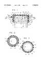
- FIG. 1is a front view of a closure system constructed according to the present invention.
- the cap portionis in cross sectional view.
- FIG. 2is a top sectional view of the closure system shown in FIG. 1, taken along lines 2--2.
- FIG. 3is a top sectional view of the closure system shown in FIG. 1, taken along lines 3--3.
- FIG. 4is a sectional view of a portion of another closure system according to the invention.
- FIG. 5is a sectional side view of the closure system shown in FIG. 1, with the cap set on the container to the predetermined position which unlocks the cap, and with a finger at the position in which the predetermined position is discovered.
- FIG. 6is a sectional side view of a preferred embodiment of the invention.
- FIG. 7is a sectional view of a tactile position indicator according to the invention.
- FIG. 8is a sectional view of a tactile position indicator according to the invention.
- FIG. 9is a frontal view of a child resistant, tamper-indicating closure of the invention incorporating the arthritic top.
- FIG. 10is a sectional view of the closure of FIG. 9 taken along the line 10--10 of FIG. 9.
- FIG. 11is a top plan view of the closure of FIG. 9.
- FIG. 12is a bottom plan view of the closure of FIG. 9.
- FIG. 13is a sectional view of the closure of FIG. 9 taken along the lines 13--13 of FIG. 10.
- FIG. 14is a sectional view of the closure of FIG. 9 taken along the lines 14--14 of FIG. 10.
- FIG. 1shows a closure system 10, on the upper portion 12 of a container body (not shown).
- the closure systemcomprises elements on neck portion 16 of upper body portion 12, in cooperation with cap 20.
- Neck 16may be cylindrical, conical or take any generally circular form when considered in cross section.
- neck 16includes annular raised retainer ridges 22, 24, 28, on the outer surface 32 of neck 16.
- the upper leading edges 36 of the retainer ridgesare preferably angled down and out as the straight angle shown in FIG. 1 or curved out and down, as is retainer ridge 72 shown in FIG. 4.
- Angled or curved leading edge 36eases initial assembly of the cap on neck 16. As it is forced down over the neck, anchor ridges 40, 42, and 44 on the inner side 46 of skirt 48 must slip over the outer diameters of the retainer ridges, and snap-in below retainer surfaces 50, thus locking the cap on the neck.
- the raised retainer and anchor ridgesare preferably, but not necessarily, molded on the surfaces from which they rise. Ridges 22, 24, and 26 are generally parallel with one another.
- Annular inner wall 54seals container opening 58 by way of cap sealing surface 62 of annular seal ring 64 bearing upon opening sealing surface 68 of neck.
- Annular seal ring 64preferably contacts with annular sealing surface 68 only in a narrow band which is set back from, and does not include, the outer surface of the neck. This provides an effective seal normal to the opening sealing surface, without incurring additional frictional resistance to rotation from contact with adjacent surfaces.
- annular tear strip 76is pulled by tab 78 out of skirt 48 by tearing the strip along bands of reduced thickness 84 and 86. This separates tear strip 76 from annular rings 88 and 92.
- annular anchor ridge 40rising from inner side 46 of the skirt, and engaging retainer surface 50 of annular raised retainer ridge 22, keeps cap 20 from being lifted away from the container opening.
- Retainer ridge 22is preferably continuous but for latch finger bypass opening 94 which is just a little wider than the latch finger.
- Anchor ridge 40is preferably discontinuous or comprises portions of lower height so that three annular raised portions remain, a narrow one that is latch finger 90, and two small pivot arcs 96, FIG. 3, which follow out from under ridge 22 when latch finger 90 is urged up through bypass opening 94.
- the three discontinuous areas 100, 102 and 104 of anchor ridge 40permit the cap to be urged upward and off from the neck by finger 108 pressure against finger grip protrusion 112.
- Retainer ridge 24has a change in shape 116, preferably a discontinuity or reduction in height, that is in line with the predetermined location. This change in shape provides tactile indication of the rotational location of the bypass opening. The tactile indication is provided to the operator by contact by a finger of the operator with change 116 during rotation of the cap by the finger while the finger is simultaneously in contact with the finger grip.
- finger grip 112 shown in FIG. 5is quite large by comparison to the finger, the tactile indication works as well with just a small finger grip, for example finger grip 122 shown in FIG. 6.
- tear strip 136is designed to accommodate a tactile indicator. Space is provided in the region between minor diameter surface 138 and the outer surface of neck 130 to allow for the volume of space taken up by tactile indicator 128 when tear strip 136 is in skirt 140.
- Tactile indicator 128 on neck 130provides tactile indication of the rotational location of bypass opening 132 when a finger is on finger grip 122, in the same manner as does change in shape 116 in retainer ridge 24 described above.
- Tactile indicator 128has a narrow raised arrowhead shape with a roughened surface that is easily detected by a passing finger.
- Retainer ridge 28 in FIGS. 1 and 5, and retainer ridge 146 in FIG. 6include narrow portions of change in shape with respect to the general shape of the remainder of the ridge. These narrow portions of change in shape are index keys 150 and 152 which provide a combination, visual, tactile, and assembly index means to help the operator locate the predetermined position, and to help in assembly to index the cap and container so that the cap will be located away from the predetermined position when the container with container with sealed closure system is delivered to the customer.
- Index key 152is a narrow, arrow shaped element that includes raised portions of ridge 146 and adjacent outer surface 156 of neck 130.
- the index keymay take whatever convenient shape desired to suit its above described purpose, such as the shapes described, and index keys 160 and 162 shown in FIGS. 7 and 8 respectively.
- cap 200comprises arthritic-grip-friendly top 201 with depending skirt 202, tear strip 203, and a tamper indicating ring 204, each having integrally molded therewith anchor ridges 400, 420 and 440, respectively.
- Annular sealing ring 640depends from the undersurface of top 201.
- top 201is longer along the axis of the cap then is the top of cap 20.
- the top portion of the capwill have a height or axial length of 0.175 inch whereas in a 38 mm closure of the type disclosed in FIGS. 9-14, the axial length of the top 201 of the cap is one-half inch.
- the present inventionincludes more surface for an enfeebled hand to grasp in order to turn cap 200.
- tear strip 203has been disposed of it reveals tactile information to the user to align the latch finger 900 of anchor ridge 400 with the opening 94 in the retainer ridge 22 of the container 12 of FIGS. 1-5; or with the bypass opening 132 of the container of FIG. 6.
- the outside of the top 201 of the closureis formed with a plurality of angled surfaces 300, octagonal, for example, in the cap disclosed herein, in order to provide the enfeebled hand gripping ridges 301 to further facilitate the rotation of cover 200 to align latch finger 900 with the latch finger bypass opening of the container.
- annular sealing ring 640also extends axially for a longer distance to contact the top of the container.
- annular tear strip 203is pulled by tab 780 to tear the strip along bands of reduced thickness 840, 860.
- Top 201is rotated to align finger grip 500 with the tactile indicator or visible arrow on latch container, thus positioning the finger 900 beneath the bypass opening.
- the reusable capis for reversibly sealing, that is, sealing and unsealing, the opening from which it is lifted.
Landscapes
- Engineering & Computer Science (AREA)
- Mechanical Engineering (AREA)
- Closures For Containers (AREA)
Abstract
Description
Claims (1)
Priority Applications (1)
| Application Number | Priority Date | Filing Date | Title |
|---|---|---|---|
| US08/291,521US5740933A (en) | 1993-12-20 | 1994-08-15 | Child proof container cap designed for manipulation by arthritic fingers |
Applications Claiming Priority (2)
| Application Number | Priority Date | Filing Date | Title |
|---|---|---|---|
| US08/169,066US5423441A (en) | 1993-12-20 | 1993-12-20 | Closure system for a container and cap |
| US08/291,521US5740933A (en) | 1993-12-20 | 1994-08-15 | Child proof container cap designed for manipulation by arthritic fingers |
Related Parent Applications (1)
| Application Number | Title | Priority Date | Filing Date |
|---|---|---|---|
| US08/169,066Continuation-In-PartUS5423441A (en) | 1993-12-20 | 1993-12-20 | Closure system for a container and cap |
Publications (1)
| Publication Number | Publication Date |
|---|---|
| US5740933Atrue US5740933A (en) | 1998-04-21 |
Family
ID=46251219
Family Applications (1)
| Application Number | Title | Priority Date | Filing Date |
|---|---|---|---|
| US08/291,521Expired - LifetimeUS5740933A (en) | 1993-12-20 | 1994-08-15 | Child proof container cap designed for manipulation by arthritic fingers |
Country Status (1)
| Country | Link |
|---|---|
| US (1) | US5740933A (en) |
Cited By (16)
| Publication number | Priority date | Publication date | Assignee | Title |
|---|---|---|---|---|
| US6170683B1 (en)* | 1999-11-16 | 2001-01-09 | Rexam Medical Packaging Inc. | Two stage dispensing cap for pressurized containers |
| US6464686B1 (en)* | 1998-01-21 | 2002-10-15 | Abbott Laboratories | Polyurethane feeding tube and associated adaptors |
| US6612450B1 (en) | 2001-03-07 | 2003-09-02 | Van Blarcom Closures, Inc. | Reversible cap |
| US6739466B1 (en) | 2002-10-03 | 2004-05-25 | Rexam Medical Packaging Inc. | Folding finger tamper-indicating band arrester |
| US20050040131A1 (en)* | 2003-08-21 | 2005-02-24 | Steve Lin | Fluid-tight dilution bottle and cap |
| US20050092751A1 (en)* | 2002-03-07 | 2005-05-05 | Brasilata S/A Embalagens Metalicas | Plastic lid for a can |
| US20060186079A1 (en)* | 2005-02-22 | 2006-08-24 | David Ziegenhorn | Screw on dispensing closure with structure for preventing removal |
| US20070181578A1 (en)* | 2003-08-01 | 2007-08-09 | James Johnson | Tamper evident fitment assembly |
| US20080093363A1 (en)* | 2005-02-22 | 2008-04-24 | Camlab Limited | Secure Sample Collection |
| US20080277367A1 (en)* | 2007-05-11 | 2008-11-13 | Yeager Don F | One-Piece Squeeze And Turn Child-Resistant Closure And Container System |
| US7513377B1 (en) | 2002-10-03 | 2009-04-07 | Rexam Closures And Containers Inc. | Folding finger tamper-indicating band arrester |
| US20090301985A1 (en)* | 2008-06-05 | 2009-12-10 | Priebe Robert N | Push tab vial assembly and methods |
| US20120000879A1 (en)* | 2010-06-30 | 2012-01-05 | Mcfarlane Ronald | Finish horizontal reinforcing rib-ring force |
| US20120219734A1 (en)* | 2011-02-28 | 2012-08-30 | Graham Packaging Company, L.P. | Blow molded rectangular container |
| USD711739S1 (en) | 2013-03-07 | 2014-08-26 | Apothecary Products, Llc | Push tab vial cover |
| USD731170S1 (en) | 2013-03-13 | 2015-06-09 | Apothecary Products, Llc | Vial |
Citations (30)
| Publication number | Priority date | Publication date | Assignee | Title |
|---|---|---|---|---|
| US3703974A (en)* | 1971-03-08 | 1972-11-28 | Leo M Boxer | Safety cap |
| US3881622A (en)* | 1973-08-20 | 1975-05-06 | Phillips Petroleum Co | Gripping end of parison to form bottle having plurality of grooves at neck end |
| US3991904A (en)* | 1973-03-26 | 1976-11-16 | Johnsen & Jorgensen (Plastics) Ltd. | Hinged closures |
| US4071156A (en)* | 1976-08-13 | 1978-01-31 | The West Company | Child resistant container-closure assembly |
| US4071943A (en)* | 1976-09-01 | 1978-02-07 | Urbani Larry E | Wax container material |
| US4280632A (en)* | 1979-09-17 | 1981-07-28 | Yukitomo Yuhara | Bottle cap |
| US4342400A (en)* | 1980-09-10 | 1982-08-03 | Precision Plastic Products Corp. | Tamper indicating closure and pressurized container |
| US4417666A (en)* | 1982-02-22 | 1983-11-29 | Johnsen & Jorgensen (Plastics) Limited | Container and closure having tamper-proof feature |
| US4449639A (en)* | 1982-12-13 | 1984-05-22 | Johnsen & Jorgensen (Plastics) Ltd. | Tamper-resistant and child-resistant closures |
| US4511051A (en)* | 1984-05-21 | 1985-04-16 | Owens-Illinois, Inc. | Child-resistant package with tamper indicating device |
| US4524876A (en)* | 1984-08-23 | 1985-06-25 | Owens-Illinois, Inc. | Tamper indicating child-resistant package |
| US4573599A (en)* | 1985-02-25 | 1986-03-04 | Owens-Illinois, Inc. | Child resistant package with tamper indicating band |
| US4591063A (en)* | 1983-09-27 | 1986-05-27 | Reinold Geiger | Flask closure system |
| US4592884A (en)* | 1984-03-12 | 1986-06-03 | Little Rapids Corp. | Method for making specimen containers |
| US4646926A (en)* | 1984-03-20 | 1987-03-03 | Robert Linkletter Associates, Inc. | Tamper resistant & tamper evident closures |
| US4658977A (en)* | 1985-10-21 | 1987-04-21 | (Nepco) Northern Eng. & Plastics Corp. | Snap on twist off tamper-proof closure for containers |
| US4676389A (en)* | 1983-07-27 | 1987-06-30 | Bankers Trust Company | Tamper-resistant container closure |
| US4687113A (en)* | 1986-07-29 | 1987-08-18 | Calmar, Inc. | Tamper evident closure |
| US4770309A (en)* | 1987-06-10 | 1988-09-13 | Tri-Tech Systems International, Inc. | Closure cap with a linerless seal and method of forming such closure and seal |
| US4811857A (en)* | 1987-06-17 | 1989-03-14 | Tri-Tech Systems International Inc. | Closure system and method of forming and using same |
| US4832220A (en)* | 1987-01-23 | 1989-05-23 | Ams Packaging | Container closure |
| US4919286A (en)* | 1988-05-27 | 1990-04-24 | Robert Linkletter Assoc. | Hinged closure and container |
| US5097974A (en)* | 1991-02-07 | 1992-03-24 | Oleg Rozenberg | Tamper-evident closures |
| US5143235A (en)* | 1990-08-15 | 1992-09-01 | Cap Snap Co. | Bottle neck having means to prevent compression of cap skirt |
| US5158194A (en)* | 1991-04-30 | 1992-10-27 | Glaxo Inc. | Safety closure with easy-open feature for handicapped and elderly individuals |
| US5213225A (en)* | 1990-05-30 | 1993-05-25 | Beeson And Sons Limited | Container and closure |
| US5351845A (en)* | 1989-04-18 | 1994-10-04 | Yellowstone Environmental Science, Inc. | Cognitive skill based child-resistant and tamper-evident closure |
| US5358129A (en)* | 1993-06-24 | 1994-10-25 | Mcneil-Ppc, Inc. | Child resistant bottle |
| US5366774A (en)* | 1990-09-14 | 1994-11-22 | Southeastern Container | Antinesting preforms for blow-molded articles |
| US5423441A (en)* | 1993-12-20 | 1995-06-13 | American Safety Closure Corp. | Closure system for a container and cap |
- 1994
- 1994-08-15USUS08/291,521patent/US5740933A/ennot_activeExpired - Lifetime
Patent Citations (30)
| Publication number | Priority date | Publication date | Assignee | Title |
|---|---|---|---|---|
| US3703974A (en)* | 1971-03-08 | 1972-11-28 | Leo M Boxer | Safety cap |
| US3991904A (en)* | 1973-03-26 | 1976-11-16 | Johnsen & Jorgensen (Plastics) Ltd. | Hinged closures |
| US3881622A (en)* | 1973-08-20 | 1975-05-06 | Phillips Petroleum Co | Gripping end of parison to form bottle having plurality of grooves at neck end |
| US4071156A (en)* | 1976-08-13 | 1978-01-31 | The West Company | Child resistant container-closure assembly |
| US4071943A (en)* | 1976-09-01 | 1978-02-07 | Urbani Larry E | Wax container material |
| US4280632A (en)* | 1979-09-17 | 1981-07-28 | Yukitomo Yuhara | Bottle cap |
| US4342400A (en)* | 1980-09-10 | 1982-08-03 | Precision Plastic Products Corp. | Tamper indicating closure and pressurized container |
| US4417666A (en)* | 1982-02-22 | 1983-11-29 | Johnsen & Jorgensen (Plastics) Limited | Container and closure having tamper-proof feature |
| US4449639A (en)* | 1982-12-13 | 1984-05-22 | Johnsen & Jorgensen (Plastics) Ltd. | Tamper-resistant and child-resistant closures |
| US4676389A (en)* | 1983-07-27 | 1987-06-30 | Bankers Trust Company | Tamper-resistant container closure |
| US4591063A (en)* | 1983-09-27 | 1986-05-27 | Reinold Geiger | Flask closure system |
| US4592884A (en)* | 1984-03-12 | 1986-06-03 | Little Rapids Corp. | Method for making specimen containers |
| US4646926A (en)* | 1984-03-20 | 1987-03-03 | Robert Linkletter Associates, Inc. | Tamper resistant & tamper evident closures |
| US4511051A (en)* | 1984-05-21 | 1985-04-16 | Owens-Illinois, Inc. | Child-resistant package with tamper indicating device |
| US4524876A (en)* | 1984-08-23 | 1985-06-25 | Owens-Illinois, Inc. | Tamper indicating child-resistant package |
| US4573599A (en)* | 1985-02-25 | 1986-03-04 | Owens-Illinois, Inc. | Child resistant package with tamper indicating band |
| US4658977A (en)* | 1985-10-21 | 1987-04-21 | (Nepco) Northern Eng. & Plastics Corp. | Snap on twist off tamper-proof closure for containers |
| US4687113A (en)* | 1986-07-29 | 1987-08-18 | Calmar, Inc. | Tamper evident closure |
| US4832220A (en)* | 1987-01-23 | 1989-05-23 | Ams Packaging | Container closure |
| US4770309A (en)* | 1987-06-10 | 1988-09-13 | Tri-Tech Systems International, Inc. | Closure cap with a linerless seal and method of forming such closure and seal |
| US4811857A (en)* | 1987-06-17 | 1989-03-14 | Tri-Tech Systems International Inc. | Closure system and method of forming and using same |
| US4919286A (en)* | 1988-05-27 | 1990-04-24 | Robert Linkletter Assoc. | Hinged closure and container |
| US5351845A (en)* | 1989-04-18 | 1994-10-04 | Yellowstone Environmental Science, Inc. | Cognitive skill based child-resistant and tamper-evident closure |
| US5213225A (en)* | 1990-05-30 | 1993-05-25 | Beeson And Sons Limited | Container and closure |
| US5143235A (en)* | 1990-08-15 | 1992-09-01 | Cap Snap Co. | Bottle neck having means to prevent compression of cap skirt |
| US5366774A (en)* | 1990-09-14 | 1994-11-22 | Southeastern Container | Antinesting preforms for blow-molded articles |
| US5097974A (en)* | 1991-02-07 | 1992-03-24 | Oleg Rozenberg | Tamper-evident closures |
| US5158194A (en)* | 1991-04-30 | 1992-10-27 | Glaxo Inc. | Safety closure with easy-open feature for handicapped and elderly individuals |
| US5358129A (en)* | 1993-06-24 | 1994-10-25 | Mcneil-Ppc, Inc. | Child resistant bottle |
| US5423441A (en)* | 1993-12-20 | 1995-06-13 | American Safety Closure Corp. | Closure system for a container and cap |
Cited By (32)
| Publication number | Priority date | Publication date | Assignee | Title |
|---|---|---|---|---|
| US6464686B1 (en)* | 1998-01-21 | 2002-10-15 | Abbott Laboratories | Polyurethane feeding tube and associated adaptors |
| WO2001036288A1 (en)* | 1999-11-16 | 2001-05-25 | Rexam Medical Packaging Inc. | Two stage dispensing cap for pressurized containers |
| GB2372985A (en)* | 1999-11-16 | 2002-09-11 | Rexam Medical Packing Inc | Two stage dispensing cap for pressurized containers |
| US6484895B2 (en)* | 1999-11-16 | 2002-11-26 | The Coca-Cola Company | Two stage dispensing cap for pressurized containers |
| GB2372985B (en)* | 1999-11-16 | 2003-07-09 | Rexam Medical Packing Inc | Two stage dispensing cap for pressurized containers |
| US6170683B1 (en)* | 1999-11-16 | 2001-01-09 | Rexam Medical Packaging Inc. | Two stage dispensing cap for pressurized containers |
| US6612450B1 (en) | 2001-03-07 | 2003-09-02 | Van Blarcom Closures, Inc. | Reversible cap |
| US20050092751A1 (en)* | 2002-03-07 | 2005-05-05 | Brasilata S/A Embalagens Metalicas | Plastic lid for a can |
| US7731048B2 (en)* | 2002-03-07 | 2010-06-08 | Brasilata S/A Embalagens Metalicas | Closure assembly with breakaway sealing portion with gripping tab |
| US7513377B1 (en) | 2002-10-03 | 2009-04-07 | Rexam Closures And Containers Inc. | Folding finger tamper-indicating band arrester |
| US6739466B1 (en) | 2002-10-03 | 2004-05-25 | Rexam Medical Packaging Inc. | Folding finger tamper-indicating band arrester |
| US20070181578A1 (en)* | 2003-08-01 | 2007-08-09 | James Johnson | Tamper evident fitment assembly |
| US20110155758A1 (en)* | 2003-08-01 | 2011-06-30 | Liqui-Box Corporation | Fitment Assembly for a Container Having a Tamper Indication Band Attached Thereto |
| US7882977B2 (en)* | 2003-08-01 | 2011-02-08 | Liqui-Box Corporation | Fitment assembly for a container having a tamper indication band attached thereto |
| US8231025B2 (en) | 2003-08-01 | 2012-07-31 | Liqui-Box Corporation | Dispensing process using tamper evident fitment assembly for a container |
| US7243807B2 (en)* | 2003-08-21 | 2007-07-17 | Pml Microbiologicals, Inc. | Fluid-tight dilution bottle and cap |
| US20050040131A1 (en)* | 2003-08-21 | 2005-02-24 | Steve Lin | Fluid-tight dilution bottle and cap |
| US20060186079A1 (en)* | 2005-02-22 | 2006-08-24 | David Ziegenhorn | Screw on dispensing closure with structure for preventing removal |
| US20080093363A1 (en)* | 2005-02-22 | 2008-04-24 | Camlab Limited | Secure Sample Collection |
| US7857154B2 (en)* | 2005-02-22 | 2010-12-28 | Camlab Limited | Container with lid and tamper-evident features |
| US20080277367A1 (en)* | 2007-05-11 | 2008-11-13 | Yeager Don F | One-Piece Squeeze And Turn Child-Resistant Closure And Container System |
| US20090301985A1 (en)* | 2008-06-05 | 2009-12-10 | Priebe Robert N | Push tab vial assembly and methods |
| US20110180540A1 (en)* | 2008-06-05 | 2011-07-28 | Apothecary Products, Inc. | Push tab vial assembly and methods |
| USD657244S1 (en) | 2008-06-05 | 2012-04-10 | Apothecary Products, Inc. | Lid for vial assembly |
| US7942280B2 (en)* | 2008-06-05 | 2011-05-17 | Apothecary Products, Inc. | Push tab vial assembly and methods |
| US8672153B2 (en) | 2008-06-05 | 2014-03-18 | Apothecary Products, Inc. | Push tab vial assembly and methods |
| US20120000879A1 (en)* | 2010-06-30 | 2012-01-05 | Mcfarlane Ronald | Finish horizontal reinforcing rib-ring force |
| US9016489B2 (en)* | 2010-06-30 | 2015-04-28 | Amcor Limited | Circumferential reinforcing groove for container finish |
| US20120219734A1 (en)* | 2011-02-28 | 2012-08-30 | Graham Packaging Company, L.P. | Blow molded rectangular container |
| US9511890B2 (en)* | 2011-02-28 | 2016-12-06 | Graham Packaging Company, L.P. | Blow molded rectangular container |
| USD711739S1 (en) | 2013-03-07 | 2014-08-26 | Apothecary Products, Llc | Push tab vial cover |
| USD731170S1 (en) | 2013-03-13 | 2015-06-09 | Apothecary Products, Llc | Vial |
Similar Documents
| Publication | Publication Date | Title |
|---|---|---|
| US5423441A (en) | Closure system for a container and cap | |
| US5740933A (en) | Child proof container cap designed for manipulation by arthritic fingers | |
| US4071156A (en) | Child resistant container-closure assembly | |
| US4036385A (en) | Safety closure for containers | |
| US5040691A (en) | Child-resistant, easy opening package | |
| CA1038801A (en) | Tamperproof cap | |
| US4682706A (en) | Tamper indicator for use with a reclosable container assembly | |
| US4595123A (en) | Tamper evident closure cap | |
| USRE29779E (en) | Child-proof and pharmacist-assisting reversible closure for containers | |
| USRE39867E1 (en) | Tamper-evident container closure | |
| US4037746A (en) | Plastic cap and bottle neck | |
| US4727998A (en) | Tamper evident closure | |
| US4457437A (en) | Tamper evident child-resistant container closure | |
| US5690246A (en) | Security containers for samples | |
| GB2222153A (en) | Child resistant cap and tube assembly | |
| US4602718A (en) | Dual-operation tamper-evident band for closures | |
| WO1999037549A1 (en) | Tamper-evident container closure | |
| US3097756A (en) | Safety closure | |
| US4570825A (en) | Tamper-evident cap construction | |
| US4454955A (en) | Child resistant package | |
| WO1990005681A1 (en) | Tamper evident closure | |
| US4570810A (en) | Cap with tamper indicating band | |
| US3439825A (en) | Container closure | |
| US3952901A (en) | Tamper-proof overcap construction | |
| US4511051A (en) | Child-resistant package with tamper indicating device |
Legal Events
| Date | Code | Title | Description |
|---|---|---|---|
| AS | Assignment | Owner name:AMERICAN SAFETY CLOSURE CORP., NEW YORK Free format text:ASSIGNMENT OF ASSIGNORS INTEREST;ASSIGNORS:CONTI, VINCENT N.;YEAGER, DON;REEL/FRAME:007120/0391;SIGNING DATES FROM 19940628 TO 19940708 | |
| STCF | Information on status: patent grant | Free format text:PATENTED CASE | |
| FPAY | Fee payment | Year of fee payment:4 | |
| AS | Assignment | Owner name:BANK OF NOVA SCOTIA, THE, GEORGIA Free format text:SECURITY AGREEMENT;ASSIGNOR:CCL PLASTIC (PLATTSBURGH), INC.;REEL/FRAME:013933/0142 Effective date:20030829 | |
| AS | Assignment | Owner name:INTRAPAC (PLATTSBURGH) INC., NEW YORK Free format text:CHANGE OF NAME;ASSIGNOR:CCL PLASTIC (PLATTSBURGH), INC.;REEL/FRAME:014567/0547 Effective date:20030917 | |
| AS | Assignment | Owner name:INTRAPAC (PLATTSBURGH) INC., NEW YORK Free format text:CHANGE OF NAME;ASSIGNOR:CCL PLASTIC (PLATTSBURGH), INC.;REEL/FRAME:014097/0361 Effective date:20030922 | |
| FEPP | Fee payment procedure | Free format text:PAYOR NUMBER ASSIGNED (ORIGINAL EVENT CODE: ASPN); ENTITY STATUS OF PATENT OWNER: SMALL ENTITY | |
| FPAY | Fee payment | Year of fee payment:8 | |
| AS | Assignment | Owner name:CCL NEWCO INC., NEW YORK Free format text:MERGER;ASSIGNOR:AMERICAN SAFETY CLOSURE CORP.;REEL/FRAME:017626/0950 Effective date:20001213 Owner name:CCL PLASTIC (PLATTSBURGH) INC., NEW YORK Free format text:CHANGE OF NAME;ASSIGNOR:CCL NEWCO INC.;REEL/FRAME:017626/0923 Effective date:20001213 | |
| AS | Assignment | Owner name:CREDIT SUISSE, AS FIRST LIEN COLLATERAL AGENT, NEW Free format text:SECURITY AGREEMENT;ASSIGNORS:INTRAPAC (HARRISONBURG) INC.;INTRAPAC (SWEDESBORO) INC.;INTRAPAC (PLATTSBURGH) INC.;REEL/FRAME:017982/0481 Effective date:20060518 Owner name:CREDIT SUISSE, AS SECOND LIEN COLLATERAL AGENT, NE Free format text:SECURITY AGREEMENT;ASSIGNORS:INTRAPAC (HARRISONBURG) INC.;INTRAPAC (SWEDESBORO) INC.;INTRAPAC (PLATTSBURGH) INC.;REEL/FRAME:017982/0491 Effective date:20060518 | |
| FPAY | Fee payment | Year of fee payment:12 | |
| AS | Assignment | Owner name:INTRAPAC (PLATTSBURGH) INC., CANADA Free format text:U.S. FIRST LIEN INTELLECTUAL PROPERTY SECURITY AGREEMENT RELEASE;ASSIGNOR:CREDIT SUISSE;REEL/FRAME:027442/0450 Effective date:20111223 Owner name:INTRAPAC (HARRISONBURG) INC., CANADA Free format text:U.S. SECOND LIEN INTELLECTUAL PROPERTY SECURITY AGREEMENT RELEASE;ASSIGNOR:CREDIT SUISSE;REEL/FRAME:027442/0822 Effective date:20111223 Owner name:INTRAPAC (PLATTSBURGH) INC., CANADA Free format text:U.S. SECOND LIEN INTELLECTUAL PROPERTY SECURITY AGREEMENT RELEASE;ASSIGNOR:CREDIT SUISSE;REEL/FRAME:027442/0822 Effective date:20111223 Owner name:INTRAPAC (SWEDESBORO) INC., CANADA Free format text:U.S. SECOND LIEN INTELLECTUAL PROPERTY SECURITY AGREEMENT RELEASE;ASSIGNOR:CREDIT SUISSE;REEL/FRAME:027442/0822 Effective date:20111223 Owner name:GENERAL ELECTRIC CAPITAL CORPORATION, ILLINOIS Free format text:SECURITY AGREEMENT;ASSIGNOR:INTRAPAC (PLATTSBURGH) INC.;REEL/FRAME:027439/0623 Effective date:20111223 Owner name:INTRAPAC (SWEDESBORO) INC., CANADA Free format text:U.S. FIRST LIEN INTELLECTUAL PROPERTY SECURITY AGREEMENT RELEASE;ASSIGNOR:CREDIT SUISSE;REEL/FRAME:027442/0450 Effective date:20111223 Owner name:INTRAPAC (HARRISONBURG) INC., CANADA Free format text:U.S. FIRST LIEN INTELLECTUAL PROPERTY SECURITY AGREEMENT RELEASE;ASSIGNOR:CREDIT SUISSE;REEL/FRAME:027442/0450 Effective date:20111223 | |
| AS | Assignment | Owner name:ANTARES CAPITAL LP, ILLINOIS Free format text:SECURITY INTEREST;ASSIGNOR:GENERAL ELECTRIC CAPITAL COMPANY;REEL/FRAME:036393/0910 Effective date:20150821 | |
| AS | Assignment | Owner name:ANTARES CAPITAL LP, AS SUCCESSOR AGENT, ILLINOIS Free format text:CORRECTIVE ASSIGNMENT TO CORRECT THE NATURE OF CONVEYANCE TO ASSIGNMENT OF INTELLECTUAL PROPERTY SECURITY AGREEMENT AND CORRECT CONVEYING AND RECEIVING PARTIES PREVIOUSLY RECORDED AT REEL: 036393 FRAME: 0910. ASSIGNOR(S) HEREBY CONFIRMS THE ASSIGNMENT OF INTELLECTUAL PROPERTY SECURITY AGREEMENT;ASSIGNOR:GENERAL ELECTRIC CAPITAL CORPORATION, AS RETIRING AGENT;REEL/FRAME:036981/0493 Effective date:20150821 | |
| AS | Assignment | Owner name:INTRAPAC (SWEDESBORO) INC., NORTH CAROLINA Free format text:RELEASE BY SECURED PARTY;ASSIGNOR:ANTARES CAPITAL LP AS SUCCESSOR AGENT BY ASSIGNMENT FROM GENERAL ELECTRIC CAPITAL CORPORATION;REEL/FRAME:044332/0922 Effective date:20171204 Owner name:INTRAPAC (HARRISONBURG) INC., NORTH CAROLINA Free format text:RELEASE BY SECURED PARTY;ASSIGNOR:ANTARES CAPITAL LP AS SUCCESSOR AGENT BY ASSIGNMENT FROM GENERAL ELECTRIC CAPITAL CORPORATION;REEL/FRAME:044332/0922 Effective date:20171204 Owner name:INTRAPAC (PLATTSBURGH) INC., NORTH CAROLINA Free format text:RELEASE BY SECURED PARTY;ASSIGNOR:ANTARES CAPITAL LP AS SUCCESSOR AGENT BY ASSIGNMENT FROM GENERAL ELECTRIC CAPITAL CORPORATION;REEL/FRAME:044332/0922 Effective date:20171204 |