US5740845A - Sealable, transportable container having a breather assembly - Google Patents
Sealable, transportable container having a breather assemblyDownload PDFInfo
- Publication number
- US5740845A US5740845AUS08/499,588US49958895AUS5740845AUS 5740845 AUS5740845 AUS 5740845AUS 49958895 AUS49958895 AUS 49958895AUS 5740845 AUS5740845 AUS 5740845A
- Authority
- US
- United States
- Prior art keywords
- box
- latch
- valve
- sealing surface
- box door
- Prior art date
- Legal status (The legal status is an assumption and is not a legal conclusion. Google has not performed a legal analysis and makes no representation as to the accuracy of the status listed.)
- Expired - Fee Related
Links
- 238000007789sealingMethods0.000claimsabstractdescription85
- 230000007246mechanismEffects0.000claimsabstractdescription48
- 235000012431wafersNutrition0.000claimsdescription22
- 239000004065semiconductorSubstances0.000claimsdescription8
- 239000000356contaminantSubstances0.000claimsdescription3
- 238000001914filtrationMethods0.000claimsdescription3
- 238000003032molecular dockingMethods0.000claims2
- 230000000717retained effectEffects0.000claims2
- 230000003749cleanlinessEffects0.000claims1
- 101000873785Homo sapiens mRNA-decapping enzyme 1AProteins0.000abstract1
- 102100035856mRNA-decapping enzyme 1AHuman genes0.000abstract1
- 238000012545processingMethods0.000description22
- 239000007789gasSubstances0.000description15
- 239000002245particleSubstances0.000description9
- IJGRMHOSHXDMSA-UHFFFAOYSA-NAtomic nitrogenChemical compoundN#NIJGRMHOSHXDMSA-UHFFFAOYSA-N0.000description6
- 238000011109contaminationMethods0.000description4
- 239000000463materialSubstances0.000description4
- 229920003023plasticPolymers0.000description4
- -1polypropylenePolymers0.000description4
- 239000004743PolypropyleneSubstances0.000description3
- 238000004320controlled atmosphereMethods0.000description3
- 230000013011matingEffects0.000description3
- 229910052757nitrogenInorganic materials0.000description3
- 239000004033plasticSubstances0.000description3
- 229920001155polypropylenePolymers0.000description3
- 238000007790scrapingMethods0.000description3
- XKRFYHLGVUSROY-UHFFFAOYSA-NArgonChemical compound[Ar]XKRFYHLGVUSROY-UHFFFAOYSA-N0.000description2
- 239000002033PVDF binderSubstances0.000description2
- 239000004793PolystyreneSubstances0.000description2
- NIXOWILDQLNWCW-UHFFFAOYSA-Nacrylic acid groupChemical groupC(C=C)(=O)ONIXOWILDQLNWCW-UHFFFAOYSA-N0.000description2
- XAGFODPZIPBFFR-UHFFFAOYSA-NaluminiumChemical compound[Al]XAGFODPZIPBFFR-UHFFFAOYSA-N0.000description2
- 229910052782aluminiumInorganic materials0.000description2
- 230000008859changeEffects0.000description2
- 230000002596correlated effectEffects0.000description2
- 230000000694effectsEffects0.000description2
- 229920001903high density polyethylenePolymers0.000description2
- 239000004700high-density polyethyleneSubstances0.000description2
- 229920001684low density polyethylenePolymers0.000description2
- 239000004702low-density polyethyleneSubstances0.000description2
- 238000012986modificationMethods0.000description2
- 230000004048modificationEffects0.000description2
- 229920002492poly(sulfone)Polymers0.000description2
- 239000004417polycarbonateSubstances0.000description2
- 229920000515polycarbonatePolymers0.000description2
- 229920000728polyesterPolymers0.000description2
- 229920001343polytetrafluoroethylenePolymers0.000description2
- 239000004810polytetrafluoroethyleneSubstances0.000description2
- 229920002981polyvinylidene fluoridePolymers0.000description2
- 239000000243solutionSubstances0.000description2
- 230000032258transportEffects0.000description2
- QTBSBXVTEAMEQO-UHFFFAOYSA-MAcetateChemical compoundCC([O-])=OQTBSBXVTEAMEQO-UHFFFAOYSA-M0.000description1
- 229910000838Al alloyInorganic materials0.000description1
- 230000005355Hall effectEffects0.000description1
- 229920004142LEXAN™Polymers0.000description1
- 239000004418LexanSubstances0.000description1
- 241001465754MetazoaSpecies0.000description1
- 239000000020NitrocelluloseSubstances0.000description1
- 229920002302Nylon 6,6Polymers0.000description1
- 239000004813Perfluoroalkoxy alkaneSubstances0.000description1
- 239000004698PolyethyleneSubstances0.000description1
- 229920000690TyvekPolymers0.000description1
- 239000004775TyvekSubstances0.000description1
- 229920010346Very Low Density Polyethylene (VLDPE)Polymers0.000description1
- FJWGYAHXMCUOOM-QHOUIDNNSA-N[(2s,3r,4s,5r,6r)-2-[(2r,3r,4s,5r,6s)-4,5-dinitrooxy-2-(nitrooxymethyl)-6-[(2r,3r,4s,5r,6s)-4,5,6-trinitrooxy-2-(nitrooxymethyl)oxan-3-yl]oxyoxan-3-yl]oxy-3,5-dinitrooxy-6-(nitrooxymethyl)oxan-4-yl] nitrateChemical compoundO([C@@H]1O[C@@H]([C@H]([C@H](O[N+]([O-])=O)[C@H]1O[N+]([O-])=O)O[C@H]1[C@@H]([C@@H](O[N+]([O-])=O)[C@H](O[N+]([O-])=O)[C@@H](CO[N+]([O-])=O)O1)O[N+]([O-])=O)CO[N+](=O)[O-])[C@@H]1[C@@H](CO[N+]([O-])=O)O[C@@H](O[N+]([O-])=O)[C@H](O[N+]([O-])=O)[C@H]1O[N+]([O-])=OFJWGYAHXMCUOOM-QHOUIDNNSA-N0.000description1
- 239000003522acrylic cementSubstances0.000description1
- 230000009471actionEffects0.000description1
- 239000000853adhesiveSubstances0.000description1
- 230000001070adhesive effectEffects0.000description1
- 238000010171animal modelMethods0.000description1
- 238000013459approachMethods0.000description1
- 229910052786argonInorganic materials0.000description1
- 238000005452bendingMethods0.000description1
- 230000015572biosynthetic processEffects0.000description1
- 229920002301cellulose acetatePolymers0.000description1
- 238000004140cleaningMethods0.000description1
- 238000010276constructionMethods0.000description1
- 238000009826distributionMethods0.000description1
- 238000005516engineering processMethods0.000description1
- 239000005038ethylene vinyl acetateSubstances0.000description1
- 229920000295expanded polytetrafluoroethylenePolymers0.000description1
- 230000004907fluxEffects0.000description1
- 239000011888foilSubstances0.000description1
- 239000011521glassSubstances0.000description1
- 239000011261inert gasSubstances0.000description1
- 238000001746injection mouldingMethods0.000description1
- 238000003780insertionMethods0.000description1
- 230000037431insertionEffects0.000description1
- 238000007689inspectionMethods0.000description1
- 239000007788liquidSubstances0.000description1
- 238000012423maintenanceMethods0.000description1
- 238000004519manufacturing processMethods0.000description1
- 239000012528membraneSubstances0.000description1
- 238000000034methodMethods0.000description1
- 238000012544monitoring processMethods0.000description1
- 229920001220nitrocellulosPolymers0.000description1
- 229920002120photoresistant polymerPolymers0.000description1
- 229920000573polyethylenePolymers0.000description1
- 229920002223polystyrenePolymers0.000description1
- 230000001105regulatory effectEffects0.000description1
- 230000003068static effectEffects0.000description1
- 238000003860storageMethods0.000description1
- 238000012546transferMethods0.000description1
- 229920000785ultra high molecular weight polyethylenePolymers0.000description1
- 125000000391vinyl groupChemical group[H]C([*])=C([H])[H]0.000description1
- 229920002554vinyl polymerPolymers0.000description1
- 238000011179visual inspectionMethods0.000description1
Images


Classifications
- H—ELECTRICITY
- H01—ELECTRIC ELEMENTS
- H01L—SEMICONDUCTOR DEVICES NOT COVERED BY CLASS H10
- H01L21/00—Processes or apparatus adapted for the manufacture or treatment of semiconductor or solid state devices or of parts thereof
- H01L21/67—Apparatus specially adapted for handling semiconductor or electric solid state devices during manufacture or treatment thereof; Apparatus specially adapted for handling wafers during manufacture or treatment of semiconductor or electric solid state devices or components ; Apparatus not specifically provided for elsewhere
- H01L21/673—Apparatus specially adapted for handling semiconductor or electric solid state devices during manufacture or treatment thereof; Apparatus specially adapted for handling wafers during manufacture or treatment of semiconductor or electric solid state devices or components ; Apparatus not specifically provided for elsewhere using specially adapted carriers or holders; Fixing the workpieces on such carriers or holders
- H01L21/6735—Closed carriers
- H01L21/67373—Closed carriers characterised by locking systems
- H—ELECTRICITY
- H01—ELECTRIC ELEMENTS
- H01L—SEMICONDUCTOR DEVICES NOT COVERED BY CLASS H10
- H01L21/00—Processes or apparatus adapted for the manufacture or treatment of semiconductor or solid state devices or of parts thereof
- H01L21/67—Apparatus specially adapted for handling semiconductor or electric solid state devices during manufacture or treatment thereof; Apparatus specially adapted for handling wafers during manufacture or treatment of semiconductor or electric solid state devices or components ; Apparatus not specifically provided for elsewhere
- H01L21/673—Apparatus specially adapted for handling semiconductor or electric solid state devices during manufacture or treatment thereof; Apparatus specially adapted for handling wafers during manufacture or treatment of semiconductor or electric solid state devices or components ; Apparatus not specifically provided for elsewhere using specially adapted carriers or holders; Fixing the workpieces on such carriers or holders
- H01L21/6735—Closed carriers
- H01L21/67389—Closed carriers characterised by atmosphere control
- H01L21/67393—Closed carriers characterised by atmosphere control characterised by the presence of atmosphere modifying elements inside or attached to the closed carrierl
- Y—GENERAL TAGGING OF NEW TECHNOLOGICAL DEVELOPMENTS; GENERAL TAGGING OF CROSS-SECTIONAL TECHNOLOGIES SPANNING OVER SEVERAL SECTIONS OF THE IPC; TECHNICAL SUBJECTS COVERED BY FORMER USPC CROSS-REFERENCE ART COLLECTIONS [XRACs] AND DIGESTS
- Y10—TECHNICAL SUBJECTS COVERED BY FORMER USPC
- Y10S—TECHNICAL SUBJECTS COVERED BY FORMER USPC CROSS-REFERENCE ART COLLECTIONS [XRACs] AND DIGESTS
- Y10S414/00—Material or article handling
- Y10S414/135—Associated with semiconductor wafer handling
- Y10S414/14—Wafer cassette transporting
Definitions
- the present inventionrelates to transportable containers for standardized mechanical interface systems for reducing particle contamination.
- a standardized mechanical interface (SMIF) systemmay be used to reduce particle fluxes onto wafers and/or reticles in semiconductor fabrication. This purpose is accomplished, in part, by mechanically ensuring that during transportation and storage the gaseous media (such as air or nitrogen) surrounding the wafers is essentially stationary relative to the wafers and by ensuring that particles from the ambient environment do not enter the immediate wafer environment.
- the SMIF conceptis based on the use of a small volume of controlled (with respect to motion, gas flow direction and external contaminants), particle-free gas to provide a clean environment for articles.
- a SMIF systemhas three main components: (1) sealed pods, having a minimal volume, used for storing and transporting cassettes holding reticles or wafers; (2) enclosures placed over cassette ports and wafer processing areas of processing stations so that the environments inside the pods and enclosures (having clean air sources) become miniature clean spaces; and (3) a transfer mechanism to load/unload wafer cassettes from a sealed pod without contamination of the wafers in the wafer cassette from external environments.
- the sealed podstypically include a box, a box door and a latch for holding the box door in a closed (or sealing) position with respect to the box.
- the enclosurestypically include a port plate, a port door and a latch for holding the port door in a closed (or sealing) position with respect to the port plate. Instead of a latch, another mechanical apparatus can be used to hold the port door in the closed position.
- Wafersare stored and transported in the pods, and are transferred from a pod to a processing station in the following manner.
- a podis placed on the interface port on top of the enclosure.
- latchesrelease the box door and the enclosure's port door simultaneously.
- the box door and the port doorare opened simultaneously so that particles which may have been on the external door surfaces are trapped ("sandwiched") between the box and interface port doors.
- a mechanical elevatorlowers the two doors, with the cassette riding on top, into the enclosure covered space.
- a manipulatorpicks up the cassette and places it onto the cassette port/elevator or other receiving area of the processing station. After processing, the reverse operation takes place.
- Processing stations with enclosuresmay have an interior region which is a controlled atmosphere; for example, controlled humidity (e.g., de-humidified), nitrogen, argon, or other appropriate gas.
- controlled humiditye.g., de-humidified
- nitrogenargon
- other appropriate gase.g., nitrogen, argon, or other appropriate gas.
- One mechanism for preventing such contaminationis to use a SMIF pod having a particle filtering system as disclosed in U.S. Pat. No. 4,724,874, and to control the environment in the interior region of the SMIF pod by the removal or introduction of appropriate gases into the SMIF pod.
- a clean room facility using a SMIF podmay wish to inject a gas for example, nitrogen, into the SMIF pod to create an inert environment.
- the seal between the box and box door of a SMIF podhas been improved to reduce leakage of the gas from inside the SMIF pod.
- seal technologyimproves, the insertion of gas into the pod will require strict monitoring of the pressure inside the pod in order to ensure that the pressure inside the pod is the same as the pressure of the interior region of the processing station.
- a small difference in pressure between the interior region of the SMIF pod and the interior region of the processing stationcan create a vacuum which holds the SMIF pod box door closed after the latch has been released and the elevator assembly has lowered. In such a case, the elevator would lower the port door, and the pod door would remain closed preventing access to the interior of the pod.
- a SMIF podcould be placed in the cargo area of an airplane.
- This pressure changecould damage the liner of the SMIF pod or force air to leave or enter the SMIF pod through a seal, possibly damaging that seal.
- One solution to these problemsis to modify a SMIF pod to add an aperture with a filter.
- a SMIF pod with only an aperture and filterwould not be able to maintain an inert environment isolated from the environment external to the SMIF pod.
- Another solution which includes actively injecting and removing gas through an outlet in the SMIF pod in order to maintain a desired pressure and clean environmentcan be expensive and, a small difference in pressure between the interior of the SMIF pod and the exterior of the SMIF pod could cause the SMIF pod box door to stick to the SMIF pod box.
- the present inventionis directed to overcome the disadvantages of the prior art.
- an object of the present inventionto provide a sealable, transportable container which can equalize the pressure inside the container to the pressure outside the container without opening the container.
- Another object of the present inventionis to provide a sealable, transportable container having a breather assembly which, upon mating with a SMIF port of a processing station, allows the pressure in the interior of the container to become equal to the pressure inside the port of the processing station.
- Another object of the present inventionis to provide a sealable, transportable container with a breather assembly that can be maintained in an open position during shipping of the container such that pressure changes outside the container will not damage the container.
- Another object of the present inventionis to provide a sealable transportable container capable of maintaining a controlled environment in the interior of the container such that when an attempt is made to open the door of the container, the door will not stick closed because of a vacuum effect within the container.
- a sealable, transportable containere.g. a SMIF pod
- the containercan be used as part of a SMIF system.
- the breather assemblyhas open and closed positions. Closing the breather assembly isolates the interior region of the container from ambient atmospheric conditions. Opening the breather assembly equalizes and/or regulates pressure inside the container, allowing the pressure inside the container to approach the pressure outside the container.
- a sealable, transportable containercomprises a box having a first sealing surface and an interior region.
- the containerfurther includes a box door having a second sealing surface so that the first sealing surface and the second sealing surface form a first seal when the box door is moved to a sealing position with respect to the box.
- the box doorhas an aperture and a valve for opening and closing the aperture. Connected to the valve is an actuator for moving the valve so that moving the actuator to a first position closes the aperture and moving the actuator to a second position opens the aperture.
- the sealable, transportable containercan further include a latch for holding the box door in the sealing position.
- the actuatorcan be connected to the latch or the actuator can be the latch.
- the latchWhen the latch is in a locked position the box door is held in the sealing position, the valve is closed and the interior region is isolated from the environment external to the container.
- the latchWhen the latch is in an unlocked position, the valve is open and gas can flow between the interior region of the container and the environment external to the container.
- the latchincludes a latch plate and a cam for moving the latch plate.
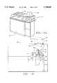
- FIG. 1Ais an isometric view of a processing station having a canopy for receiving a SMIF pod.
- FIG. 1Bis a cutaway side view of the processing station of FIG. 1A.
- FIG. 2is an exploded isometric view of a SMIF pod in accordance with the present invention.
- FIG. 3is an exploded isometric view of a SMIF pod and portions of a port assembly for receiving the SMIF pod.
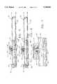
- FIG. 4is a sectional view of a SMIF pod and a port assembly for receiving the SMIF pod.
- FIG. 5is a sectional view of the box door showing the breather assembly and the latch mechanism in a locked position.
- FIG. 6is a sectional view of the box door showing the breather assembly and the latch mechanism in an unlocked position.
- FIG. 7is a blow-up sectional view of the breather assembly of FIG. 6.
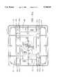
- FIGS. 8A and 9Aare plan views of a box door of a SMIF pod showing a latch mechanism and the bottom of the breather assembly in unlocked and locked positions, respectively;
- FIGS. 8B and 9Bare plan views of an alternative embodiment box door of a SMIF pod showing a latch mechanism and the bottom of the breather assembly in unlocked and locked positions, respectively.
- FIGS. 10 and 11are plan views of a two-stage rotary cam of the latch mechanism used to actuate the valve in unlocked and locked positions, respectively.
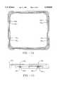
- FIG. 12is a plan view of the two-stage rotary cam.
- FIG. 13is a side view of the two-stage rotary cam.
- FIG. 14is a plan view of an interface portion of a SMIF pod box which interacts with the latch mechanism shown in FIGS. 8-9.
- FIG. 15is a partial cutaway side view of the interface portion shown in FIG. 14.
- a sealable, transportable container in accordance with the present inventionmay be used to store and transport many other inanimate objects such as magnetic recording disks, as well as living objects such as laboratory animals.
- FIGS. 1A and lBillustrate a processing station 8 having a canopy 10 which is an easily removable shield that covers the wafer handling mechanism of processing equipment 12.
- Equipment 12may be, for example, a photoresist applicator, mask aligner, inspection station or any similar processing equipment.
- a sealable transportable pod (or container) 18 including a box 20 having interior region 21 and a box door 32is mounted on horizontal surface 22 of a canopy 10 of a port assembly 24.
- Port assembly 24includes a port plate 26, port door 28, and an elevator assembly 30.
- Elevator assembly 30transports a cassette 14, containing integrated circuit wafers 16 from interior region 21 of a box 20 onto the region beneath canopy 10.
- the elevator assembly 30includes a platform 36, a shaft engagement device 38, and a drive motor 40.
- Platform 36carries port door 28, box door 32 and cassette 14 in a vertical direction.
- Platform 36is attached by engagement devices 38 to a vertical guide 42 of elevator assembly 30.
- guide 42includes a lead screw (not shown) and drive motor 40 drives a gear (not shown) which engages the lead screw for driving platform 36 up or down.
- drive motor 40drives a gear (not shown) which engages the lead screw for driving platform 36 up or down.
- a manipulator assembly shown generally by numeral 44includes a platform 46 which has an engagement means 48 for engaging vertical guide 42.
- Manipulator assembly 44includes a manipulator arm 50 and engagement head 52 adapted to engage cassette 14.
- box 20includes a domed housing 60 and a ring-like engaging portion 62.
- Housing 60 and engaging portion 62may be formed integrally, for example, by injection molding, or as separate components assembled to form box 20.
- a gasket 64which provides the seal between box 20 and box door 32 resides in a gasket-retaining slot 66 in box door 32.
- a liner(not shown) is provided on door 32 and gasket 64 contacts the liner.
- the lineris a removable element which may be formed of, for example, plastic materials which do not outgas or introduce particles, as described in U.S. Pat. No. 4,739,882, which is hereby incorporated by reference.
- the linermay also be formed of a material which provides the capability of dissipating or preventing the formation of static charges.
- a latch mechanismis housed in box door 32 and protrudes from box door 32 through windows 68 to engage latch engaging surfaces 150 1-8 (FIGS. 2 and 14-15) of box 20.
- cassette guides 70 and 72On the top surface of box door 32 are cassette guides 70 and 72, which are used to position cassette 14 (FIG. 1B) on box door 32.
- Shown on cassette guide 72is filter 74 which, as described below, is part of the breather assembly. Filter 74 and the aperture it covers are not required to be located on a cassette guide.
- FIG. 3is an exploded view of container 18 and port assembly 24.
- Port door 28has an actuating mechanism 80 with pins 82. Pins 82 fit inside holes in a cam mechanism 116 (described below). Actuating mechanism 80 rotates, thus, actuating cam 116 which translates the motion to a latch (described below) and a valve in the breather assembly (described below). Such motion translated to the latch releases the box door 32 from box 20, allowing the wafers to be removed.
- FIG. 4shows container 18 mated to port assembly 24 of processing equipment 12.
- Container 18is designed for sealably mating with the port assembly 24.
- Box 20has first and second box top sealing surfaces 91 and 92, respectively.
- Box door 32has a first box door sealing surface 93 for forming a first seal (sealably mating) with first box top sealing surface 91 when gasket 64 is compressed.
- Port plate 26has first and second port plate sealing surfaces 95 and 96, respectively.
- First port plate sealing surface 95sealably mates with second box top sealing surface 92, forming a second seal with gasket 102.
- Port door 28has a first port door sealing surface 97 which sealably mates with second port plate sealing surface 96 forming a third seal with gasket 104. Port door 28 has a second port door sealing surface 94 which sealably mates with second box door sealing surface 98 to form a fourth seal.
- FIGS. 5-7show the preferred embodiment breather assembly housed within box door 32.
- cassette guide 72On top of cassette guide 72 is a filter 74 covering an aperture 110.
- Beneath aperture 110is a valve 112 which serves to open and close aperture 110.
- Valve 112is normally held in a closed position (FIG. 5) by springs 114. Springs 114 allow valve 112 to be pivoted so that aperture 110 can be opened (FIG. 6); however, when the pivoting force is removed from valve 112, springs 114 force valve 112 to close aperture 110.
- the force that opens valve 112is provided by latch plate 118 (or other actuator) which is controlled by cam 116 (described below).
- latch plate 118When latch plate 118 is in the locked position (FIG. 5), latch plate 118 does not exert a force on valve 112.
- latch plate 118When latch plate 118 is in the unlocked position (FIG. 6), latch plate 118 pushes against valve 112 causing valve 112 to pivot.
- a containeris placed on a port.
- the portunlocks the latch which causes valve 112 to open aperture 110 and allow gas to flow between the interior region of the container 21 and the interior region of the port.
- valve 112opens aperture 110 such that when the pressure inside container 20 is greater than the pressure external to container 20 air passes from interior region 21 of container 18 through filter 74, through aperture 110, through box door upper aperture 126 (see FIG. 7), through latch plate aperture 127 (see FIG. 7), and through box door lower aperture 128. If the container is mated to a port, gas exiting lower aperture 128 would flow into the interior region of the port. Should the pressure in container 20 be less than the pressure outside box door 32, then air or other gases would travel in a path reverse to that described above.
- the aircan circulate within box door 32 and exit out apertures in the side of box door 32, air can travel through a conduit or air can be channeled to an outlet in a manner similar to that described in U.S. Pat. No. 5,169,272, incorporated herein by reference.
- the discussion of the flow of gasalso includes the flow of liquids.
- Filter 74can be used to prevent contaminants from entering container 20 or from leaving container 20.
- the preferred embodiment filteris a continuous membrane of expanded polytetrafluoroethylene (PTFE) laminated to a 100% polyester spun bonded non-woven backer.
- PTFEpolytetrafluoroethylene
- Alternative materials to PTFEare polypropylene (PP), cellulose acetate, cellulose nitrate, UHMW polyethylene, high density polyethylene (HDPE), low density polyethylene (LDPE), very low density polyethylene (VLDPE), polyvinylidene fluoride (PVDF), polysulfone (PSO), ethylene vinyl acetate (EVA), polystyrene (PS), PFA, and nylon 66.
- backerpolyester, polycarbonate, polypropylene, acetate, acrylar, kimdura, polystyrene, primalyn UPHC, Tyvek, vinyl and aluminum foil.
- adhesiveare pressure sensitive acrylic adhesive no. 200, rubber or repositionable wet surface acrylic.
- any other filters known in the artcould be used or filters known in other arts can be used, for example, a high efficiency disk drive breather falter, syringe filter, gas filter, submicron filters with electropolished and welded 316SS housings, pleated media filters, cartridge filters, and in-line filters.
- valvewould be made of polycarbonate.
- the latch platewould preferably be made of aluminum.
- valve 112would fit entirely within box door 32 (e.g., not stick out the bottom of box door 32) so that an operator is not likely to accidentally open valve 112.
- the breather assembly-latch mechanismis designed so that upon unlocking box door 32, the pressure in interior region 21 of box 20 is equalized very quickly to the pressure in the processing station so that box door 32 does not remain closed because of a vacuum effect.
- a pluginto box door aperture 128 to force valve 112 to remain in the opened position.
- This plugcould have a hole in it so that while valve 112 is in an open position, air could flow between interior region 21 and an external environment.
- This embodimentcould be used for containers shipped by airplane.
- Other alternativesinclude actuating the valve separately from the latch plate or separately from the latch, and even placing the breather assembly directly on box 20.
- Filter 74could also be used as part of a liner. When the filter is used in conjunction with the liner, the filter could be part of the liner, the filter could be below the liner or the filter could be above the liner.
- the breather assemblycan be manually operated, or automatically operated in some other fashion.
- FIGS. 8-15further explain the cam and latch mechanisms.
- the two-stage rotary cam latch mechanism of the present invention(preferred embodiment depicted in FIGS. 8A and 9A) includes latch plates 118, a cam mechanism 116 pivotally mounted on box door 32, and latch plate supports 135 1-6 .
- the operation of latch mechanismis a two-stage operation. In the first stage of operation during locking, cam mechanism 116 routes causing latch plates 118 to slide linearly. In the second stage, cam mechanism 116 rotates causing latch plates 118 to pivot on latch plate supports 135 1-6 .
- the breather assembly of the present inventioncan be used with a one stage cam or other type of cam.
- Each latch plate 118has at least one box-engaging portion.
- each of the two latch plates 118has two latch arms 142,144 and 146,148, respectively.
- Each latch armhas two latch fingers 142 1-2 , 144 1-2 , 146 1-2 , and 148 1-2 which engage respective ones of latch engaging surfaces 150 1-8 of box 20 (see FIG. 14).
- the first stage of the latching operationinvolves moving latch plates 118 from the retracted (or disengaged or unlocked) position (FIG. 8A) where latch plates 118 are entirely contained within box door 32 to the extended (or engaging or locked) position (FIG. 9A) where latch fingers 142 1-2 , 144 1-2 , 146 1-2 and 148 1-2 extend out of box door 32 and are adjacent to latch engaging surfaces 150 1-8 of box 20.
- latch fingers 142 1-2 , 144 1-2 , 146 1-2 and 148 1-2extend out of box door 32 and are adjacent to latch engaging surfaces 150 1-8 of box 20.
- the second stage of the latching operationinvolves substantially vertical motion of latch fingers 142 1-2 , 144 1-2 , 146 1-2 and 148 1-2 .
- “Substantially vertical motion”refers to motion in a direction perpendicular to the plane of box door 32, and to the plane of motion of latch plates 118 during the first stage of the latching operation.
- the motion of latch fingers 142 1-2 , 144 1-2 , 146 1-2 and 148 1-2 during the second stageengages latch fingers 142 1-2 , 144 1-2 , 146 1-2 and 148 1-2 with respective ones of latch engaging surfaces 150 1-8 , and creates a latching and/or clamping force which sealably mates first sealing surface 91 of box 20 with second sealing surface 93 of box door 32.
- valve 112 and aperture 127can be seen.
- the latch mechanismWhen the latch mechanism is in the unlocked position (FIG. 8A) the latch plate 118, at the edge of aperture 127, is exerting a force on valve 112 causing valve 112 to pivot.
- the bottom of valve 112appears on an angle. This situation is analogous to the drawing of FIG. 6.
- latch plates 118are positioned such that the latch plates 118 are not providing any force on valve 112 and thus springs 114 hold valve 112 in a closed position. This situation is analogous to the drawing of FIG. 5.
- FIGS. 8B and 9BAn alternative embodiment is shown in FIGS. 8B and 9B. Rather than have an aperture in latch plate 118B, the edge of latch plates 118B exerts a force on valve 112B. Thus, some of the gas may be deflected by the latch plate and thus circulate through cavity 154B.
- FIG. 8Bshows the alternative embodiment in the unlocked position and, FIG. 9B shows the alternative embodiment in a locked position.
- both embodimentswork fairly similar.
- a forceis exerted on valve 112, opening aperture 110.
- the latchdoes not exert a force on valve 112, and aperture 110 is closed.
- FIG. 10can be correlated with FIG. 8A.
- FIG. 11can be correlated with FIG. 9A.
- Cam mechanism 116is a two-stage cam mounted on a pivot post 160 (FIGS. 5, 6 and 13). Pivot post 160 is attached to box door 32. First and second holes 162 and 164 (FIG. 13) in cam mechanism 116 engage pins 82 and 83 of actuating mechanism 80 (FIG. 3).
- cam mechanism 116 and latch plates 118occur as follows.
- cam lobes 170 and 172engage surfaces 174 and 176 (FIGS. 10-11), respectively of latch plates 118.
- cam mechanism 116rotates through an angle of approximately 40° from an unlatched to an intermediate position
- cam lobes 170 and 172cause latch plates 116 to move from the retracted to the extended position.
- latch springs(not shown) can be attached to latch plates 116.
- Risers 180 and 182are provided on roller surface 184 of cam mechanism 116.
- cam mechanism 116rotates beyond the first 40° of motion from the intermediate position to a latched position, linear motion of latch plates 118 ceases and rollers 190 and 192 begin riding up respective ones of risers 180 and 182.
- rollers 190 and 192ride up risers 180 and 182, latch plates 118 pivot about an axis defined by the contact points of latch plates 118 and latch plate supports 135 1-6 .
- the pivoting motion of latch plates 118causes latch fingers 142 1-2 , 144 1-2 , 146 1-2 , and 148 1-2 to move substantially vertically without scraping against fingers latch surfaces 150 1-8 .
- Experimental resultshave shown that latch fingers 142 1-2 , 144 1-2 , 146 1-2 and 148 1-2 undergo horizontal motion of only approximately 0.001". This minimal amount of horizontal motion minimizes the generation of particles by scraping.
- rollers 190 and 192ride back down risers 180 and 182 as cam mechanism 116 is rotated in the opposite direction.
- Springs(not shown) provide the biasing force to keep rollers 190 and 192 in contact with risers 180 and 182.
- cam lobes 170 and 172engage cam surfaces 174 and 176 of latch plates 118 and move latch plates 118 from the extended position to the retracted position (FIG. 10).
- Rollerscan also be replaced with a slide mechanism, plastic bump or some other serf lubricated material.
- cam lobes 170 and 172are aligned with the axis of rotation of cam mechanism 116. Accordingly, any force tending to move latch plates 118 from the extended to the retracted position is transmitted along cam lobes 170 and 172 through the rotational axis of cam mechanism 116 without creating any torque which would rotate cam mechanism 116 from the latched position.
- cam lobes 170 and 172physically maintain latch plates 118 in the extended position both during the second stage of the latching operation and when the latch mechanism is in the latched orientation, preventing the latch from releasing under the application of linear impacts.
- the second stage of the latching operationprovides a strong clamping force to retain box door 32 in a sealing position with respect to box 20.
- This sealallows interior region 21 to be evacuated and back-filled with an inert gas.
- the clamping forceis approximately one (1) pound per linear inch.
- This clamping forceis regulated by a slight bowing or spring action of latch plates 118. This bowing is designed into latch plates 118 which are formed of 0.125-inch thick aluminum alloy, for example, 7075-T6.
- the clamping forceis useful to maintain a strong seal, the breather assembly will still function in an alternate embodiment where the latch plates move horizontally but not vertically.
- Latch arms 142, 144, 146 and 148are positioned at points which are half the distance from the center to the end of the edge of the box door. For a box door having a width W, latch arms are a distance approximately W/2 from each other and a distance approximately W/4 from the edge of the box door.
- each latch arm 142, 144, 146 and 148has latch fingers 142 1-2 , 144 1-2 , 146 1-2 and 148 1-8 separated by a notch.
- Posts 200serve to decrease the unsupported length of latch engaging surfaces 150 1-8 by a factor of approximately one third and to increase the shear area by a factor of 2.
- the entire latch mechanism and breather assemblyis contained in box door 32 which facilitates cleaning of box 20. Tampering with latch mechanism 80 is virtually eliminated due to the fact that outside forces intended to move latch plates 118 from the extended to the retracted position do not rotate cam mechanism 116, and cam mechanism 116 is contained within cavity 154 of box door 32. Unauthorized access would require rotating cam mechanism 116 by inserting an implement into cam holes 162 and 164. Accordingly, access can be limited by the use of an interlock system which must be activated, and/or mechanical keys which must be inserted before rotation of cam mechanism 116 is possible.
- the breather assemblyis not limited to use in conjunction with the disclosed latch.
- One skilled in the artcould use the breather assembly with various other actuating devices.
- the breather assemblycould be used with another type of latch or another type of locking device.
- the breather assemblycould be actuated directly by pins 82, a vacuum port on the port door or by a magnetic actuator (e.g. using Hall effect) on the port.
Landscapes
- Engineering & Computer Science (AREA)
- Physics & Mathematics (AREA)
- Condensed Matter Physics & Semiconductors (AREA)
- General Physics & Mathematics (AREA)
- Manufacturing & Machinery (AREA)
- Computer Hardware Design (AREA)
- Microelectronics & Electronic Packaging (AREA)
- Power Engineering (AREA)
- Container, Conveyance, Adherence, Positioning, Of Wafer (AREA)
- Packaging Frangible Articles (AREA)
Abstract
Description
Claims (34)
Priority Applications (2)
| Application Number | Priority Date | Filing Date | Title |
|---|---|---|---|
| US08/499,588US5740845A (en) | 1995-07-07 | 1995-07-07 | Sealable, transportable container having a breather assembly |
| PCT/US1996/011296WO1997003001A1 (en) | 1995-07-07 | 1996-07-03 | Sealable, transportable container having a breather assembly |
Applications Claiming Priority (1)
| Application Number | Priority Date | Filing Date | Title |
|---|---|---|---|
| US08/499,588US5740845A (en) | 1995-07-07 | 1995-07-07 | Sealable, transportable container having a breather assembly |
Publications (1)
| Publication Number | Publication Date |
|---|---|
| US5740845Atrue US5740845A (en) | 1998-04-21 |
Family
ID=23985850
Family Applications (1)
| Application Number | Title | Priority Date | Filing Date |
|---|---|---|---|
| US08/499,588Expired - Fee RelatedUS5740845A (en) | 1995-07-07 | 1995-07-07 | Sealable, transportable container having a breather assembly |
Country Status (2)
| Country | Link |
|---|---|
| US (1) | US5740845A (en) |
| WO (1) | WO1997003001A1 (en) |
Cited By (46)
| Publication number | Priority date | Publication date | Assignee | Title |
|---|---|---|---|---|
| US5846338A (en)* | 1996-01-11 | 1998-12-08 | Asyst Technologies, Inc. | Method for dry cleaning clean room containers |
| WO1999006305A1 (en)* | 1997-08-01 | 1999-02-11 | Fluoroware, Inc. | Wafer enclosure with door |
| US5879458A (en)* | 1996-09-13 | 1999-03-09 | Semifab Incorporated | Molecular contamination control system |
| US5890597A (en)* | 1997-12-19 | 1999-04-06 | Industrial Technology Research Institute | Wafer retaining mechanism |
| US5960959A (en)* | 1998-01-13 | 1999-10-05 | Industrial Technology Research Institute | Wafer retaining mechanism |
| WO1999063581A1 (en)* | 1998-06-03 | 1999-12-09 | Tec-Sem Ag | Device and method for handling a container |
| US6105781A (en)* | 1995-11-16 | 2000-08-22 | Sumitomo Metal Industries, Ltd. | Thin-plate supporting container with unitary porous gasket |
| US6116461A (en)* | 1998-05-29 | 2000-09-12 | Pyxis Corporation | Method and apparatus for the dispensing of drugs |
| US6186331B1 (en)* | 1998-04-06 | 2001-02-13 | Dainichi Shoji K.K. | Container |
| US6319297B1 (en)* | 1998-03-27 | 2001-11-20 | Asyst Technologies, Inc. | Modular SMIF pod breather, adsorbent, and purge cartridges |
| US6338409B1 (en) | 2000-04-13 | 2002-01-15 | International Business Machines Corporation | Reticle SMIF pod in situ orientation |
| US6418979B1 (en)* | 1999-02-12 | 2002-07-16 | Mid-America Commercialization Corporation | Method and apparatus for processing tool interface in a manufacturing environment |
| US6442950B1 (en)* | 2001-05-23 | 2002-09-03 | Macronix International Co., Ltd. | Cooling system of chamber with removable liner |
| US20030137151A1 (en)* | 2002-01-15 | 2003-07-24 | Eggum Shawn D. | Wafer carrier door and latching mechanism with c-shaped cam follower |
| US6623051B2 (en)* | 2000-12-13 | 2003-09-23 | Entegris, Inc. | Laterally floating latch hub assembly |
| US6641349B1 (en)* | 1999-04-30 | 2003-11-04 | Tdk Corporation | Clean box, clean transfer method and system |
| US6651704B2 (en)* | 2001-11-19 | 2003-11-25 | Taiwan Semiconductor Manufacturing Co., Ltd | Stationary and pivotable trays for semiconductor wafer transfer |
| US6679672B1 (en)* | 2003-03-10 | 2004-01-20 | Syracuse University | Transfer port for movement of materials between clean rooms |
| US6704998B1 (en)* | 1997-12-24 | 2004-03-16 | Asyst Technologies, Inc. | Port door removal and wafer handling robotic system |
| US20050006266A1 (en)* | 2003-07-08 | 2005-01-13 | Hoya Corporation | Container for housing a mask blank, method of housing a mask blank, and mask blank package |
| US20050133402A1 (en)* | 2003-12-18 | 2005-06-23 | Chiaki Matsutori | Lid unit for thin-plate supporting container |
| US20050167492A1 (en)* | 2004-02-03 | 2005-08-04 | Taiwan Semiconductor Manufacturing Co. | Smart tag holder and cover housing |
| US20050169730A1 (en)* | 2003-04-30 | 2005-08-04 | Ravinder Aggarwal | Semiconductor processing tool front end interface with sealing capability |
| US20050230284A1 (en)* | 2004-04-18 | 2005-10-20 | Tieben Anthony M | Wafer container with sealable door |
| US20050238475A1 (en)* | 2002-10-31 | 2005-10-27 | Randy Golden | System and method for stacking a predetermined number of nestable objects |
| US20060076264A1 (en)* | 2004-10-07 | 2006-04-13 | Cletuswittman Boyd | Reticle carrier |
| US7077270B2 (en)* | 2004-03-10 | 2006-07-18 | Miraial Co., Ltd. | Thin plate storage container with seal and cover fixing means |
| US20060244942A1 (en)* | 2005-02-27 | 2006-11-02 | Barry Gregerson | Substrate container with pressure equalization |
| US20070080096A1 (en)* | 2003-05-15 | 2007-04-12 | Tdk Corporation | Clean device with clean box-opening/closing device |
| US7445415B2 (en) | 2005-02-24 | 2008-11-04 | Asyst Technologies, Inc. | Direct tool loading |
| US7585142B2 (en) | 2007-03-16 | 2009-09-08 | Asm America, Inc. | Substrate handling chamber with movable substrate carrier loading platform |
| US20100054897A1 (en)* | 2005-11-07 | 2010-03-04 | Brooks Automation Inc. | Reduced capacity carrier, transport, load port, buffer system |
| US20100072204A1 (en)* | 2008-09-23 | 2010-03-25 | Smith Dennis R | Two-Piece Closure Device |
| US7740437B2 (en) | 2006-09-22 | 2010-06-22 | Asm International N.V. | Processing system with increased cassette storage capacity |
| US20100175781A1 (en)* | 2007-07-09 | 2010-07-15 | Kondoh Industries, Ltd. | Apparatus for Charging Dry Air or Nitrogen Gas into a Container for Storing Semiconductor Wafers and an Apparatus for Thereby Removing Static Electricity from the Wafers |
| US20110008136A1 (en)* | 2005-11-07 | 2011-01-13 | Brooks Automation, Inc. | Reduced capacity carrier, transport load port, buffer system |
| US8083272B1 (en)* | 1998-06-29 | 2011-12-27 | Industrial Technology Research Institute | Mechanically actuated air tight device for wafer carrier |
| US20120186692A1 (en)* | 2003-09-22 | 2012-07-26 | Battelle Memorial Institute | Container filling assembly |
| US8267634B2 (en) | 2005-11-07 | 2012-09-18 | Brooks Automation, Inc. | Reduced capacity carrier, transport, load port, buffer system |
| US8272827B2 (en) | 2005-11-07 | 2012-09-25 | Bufano Michael L | Reduced capacity carrier, transport, load port, buffer system |
| US20140116920A1 (en)* | 2012-10-25 | 2014-05-01 | Taiwan Semiconductor Manufacturing Company, Ltd. | Reticle Pod |
| CN108475651A (en)* | 2015-10-01 | 2018-08-31 | 恩特格里斯公司 | Substrate container with improved substrate holder and latch assist mechanism |
| US10173812B2 (en) | 2013-04-26 | 2019-01-08 | Entegris, Inc. | Wafer container with latching mechanism for large diameter wafers |
| US20190033732A1 (en)* | 2017-07-31 | 2019-01-31 | Taiwan Semiconductor Manufacturing Company, Ltd. | Optical reticle load port |
| US11018037B2 (en) | 2017-07-31 | 2021-05-25 | Taiwan Semiconductor Manufacturing Company, Ltd. | Optical reticle load port |
| US20220102178A1 (en)* | 2020-09-30 | 2022-03-31 | Gudeng Precision Industrial Co., Ltd. | Reticle pod having anti-collision gap structure |
Families Citing this family (8)
| Publication number | Priority date | Publication date | Assignee | Title |
|---|---|---|---|---|
| JP3872646B2 (en)* | 1998-03-09 | 2007-01-24 | コンベイ インコーポレイテッド | Packaging apparatus for articles sensitive to pollutants and package obtained therefrom |
| US7258520B2 (en) | 2002-08-31 | 2007-08-21 | Applied Materials, Inc. | Methods and apparatus for using substrate carrier movement to actuate substrate carrier door opening/closing |
| US6955197B2 (en) | 2002-08-31 | 2005-10-18 | Applied Materials, Inc. | Substrate carrier having door latching and substrate clamping mechanisms |
| TW200524073A (en) | 2003-11-13 | 2005-07-16 | Applied Materials Inc | Kinematic pin with shear member and substrate carrier for use therewith |
| US7611319B2 (en) | 2004-06-16 | 2009-11-03 | Applied Materials, Inc. | Methods and apparatus for identifying small lot size substrate carriers |
| US7409263B2 (en) | 2004-07-14 | 2008-08-05 | Applied Materials, Inc. | Methods and apparatus for repositioning support for a substrate carrier |
| US7720558B2 (en) | 2004-09-04 | 2010-05-18 | Applied Materials, Inc. | Methods and apparatus for mapping carrier contents |
| JP5105334B2 (en) | 2006-01-11 | 2012-12-26 | アプライド マテリアルズ インコーポレイテッド | Method and apparatus for purging a substrate carrier |
Citations (16)
| Publication number | Priority date | Publication date | Assignee | Title |
|---|---|---|---|---|
| US2944699A (en)* | 1958-02-14 | 1960-07-12 | Oetiker Hans | Safety device for container cover |
| US4396130A (en)* | 1981-04-10 | 1983-08-02 | Prestige Group Ltd. | Pressure cooker having safety opening means |
| US4465202A (en)* | 1981-09-23 | 1984-08-14 | British Gas Corporation | Fluid container with venting means |
| US4579244A (en)* | 1983-06-22 | 1986-04-01 | Kabushiki Kaisha Tokai Rika Denki Seisakusho | Fuel tank cap |
| US4724874A (en)* | 1986-05-01 | 1988-02-16 | Asyst Technologies | Sealable transportable container having a particle filtering system |
| US4851018A (en)* | 1986-11-28 | 1989-07-25 | Commissariat A L'energie Atomique | Installation for the storage and transfer of objects in a very clean atmosphere |
| US4924923A (en)* | 1989-05-17 | 1990-05-15 | Vernay Laboratories, Inc. | Fuel filler pipe seal |
| US4977936A (en)* | 1986-03-31 | 1990-12-18 | Stant Inc. | Filler neck sealing assembly |
| US5169272A (en)* | 1990-11-01 | 1992-12-08 | Asyst Technologies, Inc. | Method and apparatus for transferring articles between two controlled environments |
| US5217053A (en)* | 1990-02-05 | 1993-06-08 | Texas Instruments Incorporated | Vented vacuum semiconductor wafer cassette |
| US5255783A (en)* | 1991-12-20 | 1993-10-26 | Fluoroware, Inc. | Evacuated wafer container |
| US5295522A (en)* | 1992-09-24 | 1994-03-22 | International Business Machines Corporation | Gas purge system for isolation enclosure for contamination sensitive items |
| US5370257A (en)* | 1993-01-28 | 1994-12-06 | Seb S.A. | Device for automatic control of a flow limiting valve |
| US5433574A (en)* | 1992-05-21 | 1995-07-18 | Shinko Electric Co., Ltd. | Gas purge unit for a portable container |
| US5482161A (en)* | 1994-05-24 | 1996-01-09 | Fluoroware, Inc. | Mechanical interface wafer container |
| US5575081A (en)* | 1993-08-05 | 1996-11-19 | Jenoptik Gmbh | Device for transporting magazines for molding wafer-shaped objects |
- 1995
- 1995-07-07USUS08/499,588patent/US5740845A/ennot_activeExpired - Fee Related
- 1996
- 1996-07-03WOPCT/US1996/011296patent/WO1997003001A1/enactiveApplication Filing
Patent Citations (16)
| Publication number | Priority date | Publication date | Assignee | Title |
|---|---|---|---|---|
| US2944699A (en)* | 1958-02-14 | 1960-07-12 | Oetiker Hans | Safety device for container cover |
| US4396130A (en)* | 1981-04-10 | 1983-08-02 | Prestige Group Ltd. | Pressure cooker having safety opening means |
| US4465202A (en)* | 1981-09-23 | 1984-08-14 | British Gas Corporation | Fluid container with venting means |
| US4579244A (en)* | 1983-06-22 | 1986-04-01 | Kabushiki Kaisha Tokai Rika Denki Seisakusho | Fuel tank cap |
| US4977936A (en)* | 1986-03-31 | 1990-12-18 | Stant Inc. | Filler neck sealing assembly |
| US4724874A (en)* | 1986-05-01 | 1988-02-16 | Asyst Technologies | Sealable transportable container having a particle filtering system |
| US4851018A (en)* | 1986-11-28 | 1989-07-25 | Commissariat A L'energie Atomique | Installation for the storage and transfer of objects in a very clean atmosphere |
| US4924923A (en)* | 1989-05-17 | 1990-05-15 | Vernay Laboratories, Inc. | Fuel filler pipe seal |
| US5217053A (en)* | 1990-02-05 | 1993-06-08 | Texas Instruments Incorporated | Vented vacuum semiconductor wafer cassette |
| US5169272A (en)* | 1990-11-01 | 1992-12-08 | Asyst Technologies, Inc. | Method and apparatus for transferring articles between two controlled environments |
| US5255783A (en)* | 1991-12-20 | 1993-10-26 | Fluoroware, Inc. | Evacuated wafer container |
| US5433574A (en)* | 1992-05-21 | 1995-07-18 | Shinko Electric Co., Ltd. | Gas purge unit for a portable container |
| US5295522A (en)* | 1992-09-24 | 1994-03-22 | International Business Machines Corporation | Gas purge system for isolation enclosure for contamination sensitive items |
| US5370257A (en)* | 1993-01-28 | 1994-12-06 | Seb S.A. | Device for automatic control of a flow limiting valve |
| US5575081A (en)* | 1993-08-05 | 1996-11-19 | Jenoptik Gmbh | Device for transporting magazines for molding wafer-shaped objects |
| US5482161A (en)* | 1994-05-24 | 1996-01-09 | Fluoroware, Inc. | Mechanical interface wafer container |
Cited By (84)
| Publication number | Priority date | Publication date | Assignee | Title |
|---|---|---|---|---|
| US6105781A (en)* | 1995-11-16 | 2000-08-22 | Sumitomo Metal Industries, Ltd. | Thin-plate supporting container with unitary porous gasket |
| US5846338A (en)* | 1996-01-11 | 1998-12-08 | Asyst Technologies, Inc. | Method for dry cleaning clean room containers |
| US6042651A (en)* | 1996-09-13 | 2000-03-28 | Semifab Incorporated | Molecular contamination control system |
| US6221163B1 (en) | 1996-09-13 | 2001-04-24 | Semifab Incorporated | Molecular contamination control system |
| US5879458A (en)* | 1996-09-13 | 1999-03-09 | Semifab Incorporated | Molecular contamination control system |
| US6368411B2 (en) | 1996-09-13 | 2002-04-09 | Semifab Incorporated | Molecular contamination control system |
| US5957292A (en)* | 1997-08-01 | 1999-09-28 | Fluoroware, Inc. | Wafer enclosure with door |
| CN1106332C (en)* | 1997-08-01 | 2003-04-23 | 氟器皿有限公司 | Wafer enclosure with door |
| GB2341890A (en)* | 1997-08-01 | 2000-03-29 | Fluoroware Inc | Wafer enclosure with door |
| WO1999006305A1 (en)* | 1997-08-01 | 1999-02-11 | Fluoroware, Inc. | Wafer enclosure with door |
| GB2341890B (en)* | 1997-08-01 | 2002-02-20 | Fluoroware Inc | Wafer enclosure with door |
| US5890597A (en)* | 1997-12-19 | 1999-04-06 | Industrial Technology Research Institute | Wafer retaining mechanism |
| US6704998B1 (en)* | 1997-12-24 | 2004-03-16 | Asyst Technologies, Inc. | Port door removal and wafer handling robotic system |
| US5960959A (en)* | 1998-01-13 | 1999-10-05 | Industrial Technology Research Institute | Wafer retaining mechanism |
| US6319297B1 (en)* | 1998-03-27 | 2001-11-20 | Asyst Technologies, Inc. | Modular SMIF pod breather, adsorbent, and purge cartridges |
| USRE39241E1 (en)* | 1998-03-27 | 2006-08-22 | Entegris, Inc. | Modular SMIF pod breather, adsorbent, and purge cartridges |
| US6186331B1 (en)* | 1998-04-06 | 2001-02-13 | Dainichi Shoji K.K. | Container |
| US7040504B2 (en) | 1998-05-29 | 2006-05-09 | Cardinal Health 301, Inc. | System and apparatus for the dispensing of drugs |
| US6338007B1 (en) | 1998-05-29 | 2002-01-08 | Pyxis Corporation | System and apparatus for the storage and dispensing of items |
| US6116461A (en)* | 1998-05-29 | 2000-09-12 | Pyxis Corporation | Method and apparatus for the dispensing of drugs |
| US7630789B2 (en) | 1998-05-29 | 2009-12-08 | CareFusion 303 Inc. | System and apparatus for the dispensing of drugs |
| WO1999063581A1 (en)* | 1998-06-03 | 1999-12-09 | Tec-Sem Ag | Device and method for handling a container |
| CH693309A5 (en)* | 1998-06-03 | 2003-05-30 | Tec Sem Ag | Device and method for handling a container. |
| US8083272B1 (en)* | 1998-06-29 | 2011-12-27 | Industrial Technology Research Institute | Mechanically actuated air tight device for wafer carrier |
| US6418979B1 (en)* | 1999-02-12 | 2002-07-16 | Mid-America Commercialization Corporation | Method and apparatus for processing tool interface in a manufacturing environment |
| US20040035493A1 (en)* | 1999-04-30 | 2004-02-26 | Tdk Corporation | Clean box, clean transfer method and system |
| US6641349B1 (en)* | 1999-04-30 | 2003-11-04 | Tdk Corporation | Clean box, clean transfer method and system |
| US6796763B2 (en)* | 1999-04-30 | 2004-09-28 | Tdk Corporation | Clean box, clean transfer method and system |
| US6338409B1 (en) | 2000-04-13 | 2002-01-15 | International Business Machines Corporation | Reticle SMIF pod in situ orientation |
| US6623051B2 (en)* | 2000-12-13 | 2003-09-23 | Entegris, Inc. | Laterally floating latch hub assembly |
| US6442950B1 (en)* | 2001-05-23 | 2002-09-03 | Macronix International Co., Ltd. | Cooling system of chamber with removable liner |
| US6651704B2 (en)* | 2001-11-19 | 2003-11-25 | Taiwan Semiconductor Manufacturing Co., Ltd | Stationary and pivotable trays for semiconductor wafer transfer |
| US20030137151A1 (en)* | 2002-01-15 | 2003-07-24 | Eggum Shawn D. | Wafer carrier door and latching mechanism with c-shaped cam follower |
| US6955382B2 (en)* | 2002-01-15 | 2005-10-18 | Entegris, Inc. | Wafer carrier door and latching mechanism with c-shaped cam follower |
| US20050238475A1 (en)* | 2002-10-31 | 2005-10-27 | Randy Golden | System and method for stacking a predetermined number of nestable objects |
| US6679672B1 (en)* | 2003-03-10 | 2004-01-20 | Syracuse University | Transfer port for movement of materials between clean rooms |
| US20050169730A1 (en)* | 2003-04-30 | 2005-08-04 | Ravinder Aggarwal | Semiconductor processing tool front end interface with sealing capability |
| US20070080096A1 (en)* | 2003-05-15 | 2007-04-12 | Tdk Corporation | Clean device with clean box-opening/closing device |
| US20100108564A1 (en)* | 2003-05-15 | 2010-05-06 | Tdk Corporation | Clean device with clean box-opening/closing device |
| US7674083B2 (en) | 2003-05-15 | 2010-03-09 | Tdk Corporation | Clean device with clean box-opening/closing device |
| US7463338B2 (en)* | 2003-07-08 | 2008-12-09 | Hoya Corporation | Container for housing a mask blank, method of housing a mask blank, and mask blank package |
| US20050006266A1 (en)* | 2003-07-08 | 2005-01-13 | Hoya Corporation | Container for housing a mask blank, method of housing a mask blank, and mask blank package |
| US7838182B2 (en) | 2003-07-08 | 2010-11-23 | Hoya Corporation | Container for housing a mask blank, method of housing a mask blank, and mask blank package |
| US20090035666A1 (en)* | 2003-07-08 | 2009-02-05 | Hoya Corporation | Container for housing a mask blank, method of housing a mask blank, and mask blank package |
| US20090029271A1 (en)* | 2003-07-08 | 2009-01-29 | Hoya Corporation | Container for housing a mask blank, method of housing a mask blank, and mask blank package |
| US8919392B2 (en)* | 2003-09-22 | 2014-12-30 | Lawrence Bullen | Container filling assembly |
| US20120186692A1 (en)* | 2003-09-22 | 2012-07-26 | Battelle Memorial Institute | Container filling assembly |
| US7784640B2 (en) | 2003-12-18 | 2010-08-31 | Miraial Co., Ltd. | Lid attaching mechanism with camming unit for thin-plate supporting container |
| US20060102632A1 (en)* | 2003-12-18 | 2006-05-18 | Miraial Co., Ltd. | Lid unit for thin-plate supporting container |
| US20050133402A1 (en)* | 2003-12-18 | 2005-06-23 | Chiaki Matsutori | Lid unit for thin-plate supporting container |
| US7328836B2 (en)* | 2004-02-03 | 2008-02-12 | Taiwan Semiconductor Manufacturing Co., Ltd. | Smart tag holder and cover housing |
| US20050167492A1 (en)* | 2004-02-03 | 2005-08-04 | Taiwan Semiconductor Manufacturing Co. | Smart tag holder and cover housing |
| US7077270B2 (en)* | 2004-03-10 | 2006-07-18 | Miraial Co., Ltd. | Thin plate storage container with seal and cover fixing means |
| US7578407B2 (en) | 2004-04-18 | 2009-08-25 | Entegris, Inc. | Wafer container with sealable door |
| US20050230284A1 (en)* | 2004-04-18 | 2005-10-20 | Tieben Anthony M | Wafer container with sealable door |
| US20060076264A1 (en)* | 2004-10-07 | 2006-04-13 | Cletuswittman Boyd | Reticle carrier |
| US7380668B2 (en) | 2004-10-07 | 2008-06-03 | Fab Integrated Technology, Inc. | Reticle carrier |
| US7445415B2 (en) | 2005-02-24 | 2008-11-04 | Asyst Technologies, Inc. | Direct tool loading |
| US7528936B2 (en) | 2005-02-27 | 2009-05-05 | Entegris, Inc. | Substrate container with pressure equalization |
| US20060244942A1 (en)* | 2005-02-27 | 2006-11-02 | Barry Gregerson | Substrate container with pressure equalization |
| US8267634B2 (en) | 2005-11-07 | 2012-09-18 | Brooks Automation, Inc. | Reduced capacity carrier, transport, load port, buffer system |
| US9224628B2 (en) | 2005-11-07 | 2015-12-29 | Brooks Automation. Inc. | Reduced capacity carrier, transport, load port, buffer system |
| US20110008136A1 (en)* | 2005-11-07 | 2011-01-13 | Brooks Automation, Inc. | Reduced capacity carrier, transport load port, buffer system |
| US10679882B2 (en) | 2005-11-07 | 2020-06-09 | Brooks Automation, Inc | Reduced capacity carrier, transport, load port, buffer system |
| US8328495B2 (en)* | 2005-11-07 | 2012-12-11 | Brooks Automation, Inc. | Reduced capacity carrier, transport, load port, buffer system |
| US8272827B2 (en) | 2005-11-07 | 2012-09-25 | Bufano Michael L | Reduced capacity carrier, transport, load port, buffer system |
| US20100054897A1 (en)* | 2005-11-07 | 2010-03-04 | Brooks Automation Inc. | Reduced capacity carrier, transport, load port, buffer system |
| US7740437B2 (en) | 2006-09-22 | 2010-06-22 | Asm International N.V. | Processing system with increased cassette storage capacity |
| US7585142B2 (en) | 2007-03-16 | 2009-09-08 | Asm America, Inc. | Substrate handling chamber with movable substrate carrier loading platform |
| US20100175781A1 (en)* | 2007-07-09 | 2010-07-15 | Kondoh Industries, Ltd. | Apparatus for Charging Dry Air or Nitrogen Gas into a Container for Storing Semiconductor Wafers and an Apparatus for Thereby Removing Static Electricity from the Wafers |
| US20100072204A1 (en)* | 2008-09-23 | 2010-03-25 | Smith Dennis R | Two-Piece Closure Device |
| US8251238B2 (en) | 2008-09-23 | 2012-08-28 | Tdw Delaware Inc. | Two-piece closure device |
| US20140116920A1 (en)* | 2012-10-25 | 2014-05-01 | Taiwan Semiconductor Manufacturing Company, Ltd. | Reticle Pod |
| US9412632B2 (en)* | 2012-10-25 | 2016-08-09 | Taiwan Semiconductor Manufacturing Company, Ltd. | Reticle pod |
| US10723525B2 (en) | 2013-04-26 | 2020-07-28 | Entegris, Inc. | Wafer container with latching mechanism for large diameter wafers |
| US10173812B2 (en) | 2013-04-26 | 2019-01-08 | Entegris, Inc. | Wafer container with latching mechanism for large diameter wafers |
| CN108475651A (en)* | 2015-10-01 | 2018-08-31 | 恩特格里斯公司 | Substrate container with improved substrate holder and latch assist mechanism |
| CN108475651B (en)* | 2015-10-01 | 2022-10-11 | 恩特格里斯公司 | Substrate container with improved substrate holder and door latch assist mechanism |
| US20190033732A1 (en)* | 2017-07-31 | 2019-01-31 | Taiwan Semiconductor Manufacturing Company, Ltd. | Optical reticle load port |
| US11018037B2 (en) | 2017-07-31 | 2021-05-25 | Taiwan Semiconductor Manufacturing Company, Ltd. | Optical reticle load port |
| US10503082B2 (en)* | 2017-07-31 | 2019-12-10 | Taiwan Semiconductor Manufacturing Company, Ltd. | Optical reticle load port |
| US20220102178A1 (en)* | 2020-09-30 | 2022-03-31 | Gudeng Precision Industrial Co., Ltd. | Reticle pod having anti-collision gap structure |
| US20220104365A1 (en)* | 2020-09-30 | 2022-03-31 | Gudeng Precision Industrial Co., Ltd. | Substrate storage apparatus provided with storage environment detection |
| US12198958B2 (en)* | 2020-09-30 | 2025-01-14 | Gudeng Precision Industrial Co., Ltd. | Substrate storage apparatus provided with storage environment detection |
Also Published As
| Publication number | Publication date |
|---|---|
| WO1997003001A1 (en) | 1997-01-30 |
Similar Documents
| Publication | Publication Date | Title |
|---|---|---|
| US5740845A (en) | Sealable, transportable container having a breather assembly | |
| US4995430A (en) | Sealable transportable container having improved latch mechanism | |
| US11978648B2 (en) | Substrate transport | |
| US5469963A (en) | Sealable transportable container having improved liner | |
| US5547328A (en) | Method and apparatus for transferring articles between two controlled environments | |
| US5895191A (en) | Sealable, transportable container adapted for horizontal loading and unloading | |
| US4674939A (en) | Sealed standard interface apparatus | |
| US4534389A (en) | Interlocking door latch for dockable interface for integrated circuit processing | |
| JP2533283B2 (en) | Airlock Transfer Port and Reduced Pollution Manufacturing System | |
| JP3202991B2 (en) | Closed, sealable and scavengable semiconductor wafer holding device | |
| US6955197B2 (en) | Substrate carrier having door latching and substrate clamping mechanisms | |
| US5653565A (en) | SMIF port interface adaptor | |
| US7258520B2 (en) | Methods and apparatus for using substrate carrier movement to actuate substrate carrier door opening/closing | |
| WO2001004028A1 (en) | Smif-compatible open cassette enclosure | |
| US6533521B1 (en) | Integrated substrate handler having pre-aligner and storage pod access mechanism | |
| EP0151336B1 (en) | System for integrated circuit processing | |
| CN118215885A (en) | Material storage device system | |
| US6945405B1 (en) | Transport module with latching door | |
| JPH07112002B2 (en) | Moving container | |
| TW202332987A (en) | Reticle pod having latch including ramped surface | |
| WO2004021413A1 (en) | Substrate carrier having door latching and substrate clamping mechanisms | |
| WO2002080232A2 (en) | Substrate storage pod access device |
Legal Events
| Date | Code | Title | Description |
|---|---|---|---|
| AS | Assignment | Owner name:ASYST TECHNOLOGIES, INC., CALIFORNIA Free format text:ASSIGNMENT OF ASSIGNORS INTEREST;ASSIGNORS:BONORA, ANTHONY C.;ROSENQUIST, FREDERICK T.;JAIN, SUDHIR;AND OTHERS;REEL/FRAME:007873/0865;SIGNING DATES FROM 19951009 TO 19951020 | |
| CC | Certificate of correction | ||
| FEPP | Fee payment procedure | Free format text:PAYOR NUMBER ASSIGNED (ORIGINAL EVENT CODE: ASPN); ENTITY STATUS OF PATENT OWNER: LARGE ENTITY | |
| FPAY | Fee payment | Year of fee payment:4 | |
| FEPP | Fee payment procedure | Free format text:PAYOR NUMBER ASSIGNED (ORIGINAL EVENT CODE: ASPN); ENTITY STATUS OF PATENT OWNER: LARGE ENTITY Free format text:PAYER NUMBER DE-ASSIGNED (ORIGINAL EVENT CODE: RMPN); ENTITY STATUS OF PATENT OWNER: LARGE ENTITY | |
| AS | Assignment | Owner name:ENTEGRIS CAYMAN LTD., MINNESOTA Free format text:ASSIGNMENT OF ASSIGNORS INTEREST;ASSIGNOR:ASYST TECHNOLOGIES, INC.;REEL/FRAME:014196/0553 Effective date:20030509 | |
| AS | Assignment | Owner name:ENTEGRIS, INC., MINNESOTA Free format text:ASSIGNMENT OF ASSIGNORS INTEREST;ASSIGNOR:ENTEGRIS CAYMEN LTD.;REEL/FRAME:016195/0486 Effective date:20040218 | |
| FPAY | Fee payment | Year of fee payment:8 | |
| REMI | Maintenance fee reminder mailed | ||
| FEPP | Fee payment procedure | Free format text:PAYER NUMBER DE-ASSIGNED (ORIGINAL EVENT CODE: RMPN); ENTITY STATUS OF PATENT OWNER: LARGE ENTITY Free format text:PAYOR NUMBER ASSIGNED (ORIGINAL EVENT CODE: ASPN); ENTITY STATUS OF PATENT OWNER: LARGE ENTITY | |
| AS | Assignment | Owner name:ENTEGRIS, INC. (DELAWARE CORPORATION), MASSACHUSET Free format text:MERGER;ASSIGNOR:ENTEGRIS, INC. (MINNESOTA CORPORATION;REEL/FRAME:023839/0826 Effective date:20050805 | |
| LAPS | Lapse for failure to pay maintenance fees | ||
| STCH | Information on status: patent discontinuation | Free format text:PATENT EXPIRED DUE TO NONPAYMENT OF MAINTENANCE FEES UNDER 37 CFR 1.362 | |
| FP | Lapsed due to failure to pay maintenance fee | Effective date:20100421 |