US5740829A - Method of sealing an outlet opening - Google Patents
Method of sealing an outlet openingDownload PDFInfo
- Publication number
- US5740829A US5740829AUS08/506,609US50660995AUS5740829AUS 5740829 AUS5740829 AUS 5740829AUS 50660995 AUS50660995 AUS 50660995AUS 5740829 AUS5740829 AUS 5740829A
- Authority
- US
- United States
- Prior art keywords
- pipeline
- flange
- seal
- joint
- branch line
- Prior art date
- Legal status (The legal status is an assumption and is not a legal conclusion. Google has not performed a legal analysis and makes no representation as to the accuracy of the status listed.)
- Expired - Fee Related
Links
Images


Classifications
- F—MECHANICAL ENGINEERING; LIGHTING; HEATING; WEAPONS; BLASTING
- F16—ENGINEERING ELEMENTS AND UNITS; GENERAL MEASURES FOR PRODUCING AND MAINTAINING EFFECTIVE FUNCTIONING OF MACHINES OR INSTALLATIONS; THERMAL INSULATION IN GENERAL
- F16L—PIPES; JOINTS OR FITTINGS FOR PIPES; SUPPORTS FOR PIPES, CABLES OR PROTECTIVE TUBING; MEANS FOR THERMAL INSULATION IN GENERAL
- F16L41/00—Branching pipes; Joining pipes to walls
- F16L41/04—Tapping pipe walls, i.e. making connections through the walls of pipes while they are carrying fluids; Fittings therefor
- F—MECHANICAL ENGINEERING; LIGHTING; HEATING; WEAPONS; BLASTING
- F16—ENGINEERING ELEMENTS AND UNITS; GENERAL MEASURES FOR PRODUCING AND MAINTAINING EFFECTIVE FUNCTIONING OF MACHINES OR INSTALLATIONS; THERMAL INSULATION IN GENERAL
- F16L—PIPES; JOINTS OR FITTINGS FOR PIPES; SUPPORTS FOR PIPES, CABLES OR PROTECTIVE TUBING; MEANS FOR THERMAL INSULATION IN GENERAL
- F16L55/00—Devices or appurtenances for use in, or in connection with, pipes or pipe systems
- F16L55/10—Means for stopping flow in pipes or hoses
- F—MECHANICAL ENGINEERING; LIGHTING; HEATING; WEAPONS; BLASTING
- F16—ENGINEERING ELEMENTS AND UNITS; GENERAL MEASURES FOR PRODUCING AND MAINTAINING EFFECTIVE FUNCTIONING OF MACHINES OR INSTALLATIONS; THERMAL INSULATION IN GENERAL
- F16L—PIPES; JOINTS OR FITTINGS FOR PIPES; SUPPORTS FOR PIPES, CABLES OR PROTECTIVE TUBING; MEANS FOR THERMAL INSULATION IN GENERAL
- F16L55/00—Devices or appurtenances for use in, or in connection with, pipes or pipe systems
- F16L55/18—Appliances for use in repairing pipes
- Y—GENERAL TAGGING OF NEW TECHNOLOGICAL DEVELOPMENTS; GENERAL TAGGING OF CROSS-SECTIONAL TECHNOLOGIES SPANNING OVER SEVERAL SECTIONS OF THE IPC; TECHNICAL SUBJECTS COVERED BY FORMER USPC CROSS-REFERENCE ART COLLECTIONS [XRACs] AND DIGESTS
- Y10—TECHNICAL SUBJECTS COVERED BY FORMER USPC
- Y10T—TECHNICAL SUBJECTS COVERED BY FORMER US CLASSIFICATION
- Y10T137/00—Fluid handling
- Y10T137/0318—Processes
- Y10T137/0402—Cleaning, repairing, or assembling
- Y10T137/0441—Repairing, securing, replacing, or servicing pipe joint, valve, or tank
- Y10T137/0458—Tapping pipe, keg, or tank
- Y10T137/0463—Particular aperture forming means
- Y10T137/0475—Having deformable or inflatable means
- Y—GENERAL TAGGING OF NEW TECHNOLOGICAL DEVELOPMENTS; GENERAL TAGGING OF CROSS-SECTIONAL TECHNOLOGIES SPANNING OVER SEVERAL SECTIONS OF THE IPC; TECHNICAL SUBJECTS COVERED BY FORMER USPC CROSS-REFERENCE ART COLLECTIONS [XRACs] AND DIGESTS
- Y10—TECHNICAL SUBJECTS COVERED BY FORMER USPC
- Y10T—TECHNICAL SUBJECTS COVERED BY FORMER US CLASSIFICATION
- Y10T137/00—Fluid handling
- Y10T137/4238—With cleaner, lubrication added to fluid or liquid sealing at valve interface
- Y10T137/4245—Cleaning or steam sterilizing
- Y10T137/4273—Mechanical cleaning
- Y—GENERAL TAGGING OF NEW TECHNOLOGICAL DEVELOPMENTS; GENERAL TAGGING OF CROSS-SECTIONAL TECHNOLOGIES SPANNING OVER SEVERAL SECTIONS OF THE IPC; TECHNICAL SUBJECTS COVERED BY FORMER USPC CROSS-REFERENCE ART COLLECTIONS [XRACs] AND DIGESTS
- Y10—TECHNICAL SUBJECTS COVERED BY FORMER USPC
- Y10T—TECHNICAL SUBJECTS COVERED BY FORMER US CLASSIFICATION
- Y10T137/00—Fluid handling
- Y10T137/598—With repair, tapping, assembly, or disassembly means
- Y10T137/612—Tapping a pipe, keg, or apertured tank under pressure
- Y10T137/6123—With aperture forming means
- Y—GENERAL TAGGING OF NEW TECHNOLOGICAL DEVELOPMENTS; GENERAL TAGGING OF CROSS-SECTIONAL TECHNOLOGIES SPANNING OVER SEVERAL SECTIONS OF THE IPC; TECHNICAL SUBJECTS COVERED BY FORMER USPC CROSS-REFERENCE ART COLLECTIONS [XRACs] AND DIGESTS
- Y10—TECHNICAL SUBJECTS COVERED BY FORMER USPC
- Y10T—TECHNICAL SUBJECTS COVERED BY FORMER US CLASSIFICATION
- Y10T29/00—Metal working
- Y10T29/49—Method of mechanical manufacture
- Y10T29/49826—Assembling or joining
- Y10T29/49895—Associating parts by use of aligning means [e.g., use of a drift pin or a "fixture"]
- Y—GENERAL TAGGING OF NEW TECHNOLOGICAL DEVELOPMENTS; GENERAL TAGGING OF CROSS-SECTIONAL TECHNOLOGIES SPANNING OVER SEVERAL SECTIONS OF THE IPC; TECHNICAL SUBJECTS COVERED BY FORMER USPC CROSS-REFERENCE ART COLLECTIONS [XRACs] AND DIGESTS
- Y10—TECHNICAL SUBJECTS COVERED BY FORMER USPC
- Y10T—TECHNICAL SUBJECTS COVERED BY FORMER US CLASSIFICATION
- Y10T29/00—Metal working
- Y10T29/53—Means to assemble or disassemble
- Y10T29/53978—Means to assemble or disassemble including means to relatively position plural work parts
Definitions
- This inventionrelates to methods of sealing an outlet opening.
- the methodis particularly, though not exclusively, applicable to sealing an outlet opening of a branch line in a gas transmission pipeline.
- a branch linecommonly is connected to a fitting which is located on the underside of a horizontal pipeline though the pipeline need not be horizontal and the branch line may be positioned at any position around the latter.
- a common requirementis to allow work to be carried out to the branch line without interrupting flow of gas through the pipeline.
- a known methodinvolves the insertion of a by-pass, followed by stopping off of the pipeline on either side of the branch line. This involves considerable effort and expenditure of time.
- An alternative methodis to shut down and depressurise the pipeline. This is not always convenient, especially during times of peak gas demand.
- An object of the inventionis to avoid the use of a by-pass or complete shut down of the pipeline.
- a method of sealing the outlet opening to a branch line in a pipelinecomprises using a seal applied to the outlet opening from the inside of the pipeline, a joint-flange being welded to the pipeline opposite to the branch line allowing an access opening to be cut through the wall of the pipeline and the seal to be inserted into the pipeline and applied to the outlet opening.
- a jigis used to locate the joint-flange in relation to the pipeline to facilitate the welding of the joint-flange in the correct position.
- the sealis composed of synthetic plastics material.
- the sealhas a sealing face which is of part-cylindrical shape, the radius of curvature of said face matching the radius of curvature of the inside wall of the pipeline.
- the sealis mounted at one end of a red inserted through a hollow externally screw threaded tube, which is screwed through an internally screw threaded flange plate secured on an isolation valve secured on the joint-flange, the rod being prevented from rotating while the tube is screwed to advance the seal into position.
- FIG. 1shows the pipeline with a fitting to which a branch line is connected and the joint-flange together with an exploded view of a jig used to position the joint-flange correctly on the pipeline opposite to the fitting;
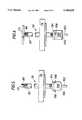
- FIG. 2is a side elevation, partly in vertical section, of the part of the pipeline, shown in FIG. 1, showing the joint-flange and an isolation valve, with the seal in position to be applied to the outlet opening by an insertion rod sub-assembly;
- FIG. 3is a side-elevation similar to FIG. 2 but showing the seal about to be positioned at the outlet opening;
- FIG. 4is an enlarged view of the insertion rod sub-assembly
- FIGS. 5 and 6are vertical elevations of the insertion rod sub-assembly showing the seal in two positions, one at right angles to the other;
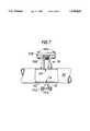
- FIG. 7is a side elevation, partly in vertical section, of the part of the pipeline shown in FIGS. 1 and 2 but showing a blanking flange fitted to the joint-flange after work on the branch line has been completed.
- FIG. 1shows part of a gas transmission pipeline 10 having a fitting 12 located at its nnderside. The requirement is to seal the outlet opening 14 to the branch line without the need to interrupt the flow of gas through the pipeline 10.
- the first step(shown in FIG. 1) is to weld a joint-flange 16 to the pipeline 10 opposite to the fitting 12.
- a jig 20is used.
- the jig 20comprises a rectangular frame having sides 21 and ends 22 having four parallel arms 24, 26, 28, 30, which can be moved in pairs along the frame sides 21 and clamped in position.
- An upper bridge 32is slidable on the upper arms 24, 26.
- a lower bridge 34is slidable on the lower arms 28, 30.
- the jig 20is used as follows:
- shoes 36are selected to match the external curvature of the pipe 10, two shoes 36 being bolted to the upper bridge 32 and two to the lower bridge 34;
- the joint-flange 16is bolted to a fixing flange 38, which is welded to the upper bridge 32 at 39 and positioned on the pipeline 10 approximately opposite to the branch line 40;
- the lower bridge 34is assembled upon the lower jig arms 28, 30 with the short side 42 of the mounting bosses towards the jig sides 22 and clamped in position to suit the size of pipeline 10.
- the arms 28, 30are engraved with the various pipe sizes. Adjust the branch line clamping screws 44, 46, 48 and 50 to a central gap of approximately 130 millimeters. Note that the fourth branch line clamping screw is received in a keep 52 which has side-apertures 54 allowing the screws 44 and 46 to pass through the keep 52.
- the upper arms 24, 26are now set to position to suit the pipe size indicated on the sides 21 and are now clamped in place;
- the jig 20is next offered up to the pipeline 10 and the upper arms 24, 26 are located in the bosses 56 of the upper bridge 32. The sides 21 are pushed up against the pipeline 10 and the upper bridge 32 is clamped onto the upper arms 24, 26;
- the jig 20is slid along the pipeline 10 until the centre-line of the branch clamping screws 44, 46, 48 and 50 is aligned with the centre-line of the branch 40; the lower arms 28, 30 are then clamped firmly in position;
- the jig 20is held in position while the branch clamping screws 44, 46, 48 are adjusted until all three screws engage the narrow part of the fitting 12 to which the branch 40 is connected;
- the joint-flange 16is next tack-welded to the pipeline 10;
- the jig 20is unbolted from the joint-flange 16 and removed and the joint-flange 16 is fully welded to the pipeline 10.
- the next stage in the methodis to cut an access hole 60 through the wall 62 of the pipeline 10.
- an isolation valve 64is fitted on top of the joint-flange 16 and secured by bolts 66.
- a drilling machine(not shown) is fitted on top of the isolation valve 64. The valve is opened and the access hole 60 is cut using the drilling machine.
- the drillis withdrawn, the valve is closed and the drilling machine is removed.
- an insertion rod sub-assembly 70is fitted to the isolation valve 64.
- a brush 87is secured to the lower end of the sub-assembly and used to clean the area of the inner wall of the pipeline 10 around the branch outlet 14.
- the tee bar handle 72is turned manually to rotate the brush.
- the sub-assemblyincludes a flange 74 having a grease injection point 76. Grease is injected through the point 76 into the thread connection in the flange 74. This can be used to stop any escape of gas leaking from the threads.
- the sub-assemblyis withdrawn after the cleaning step has been completed and the valve 64 is closed.
- the flange 74 and the sub-assemblycan then be removed.
- FIG. 4shows the sub-assembly 70 in more detail (note that the flange 74 is not shown).
- the sub-assembly 70comprises a rod 80 which extends through a hollow tube 82 having an external screw-thread. At its upper end the rod 80 carries the tee-handle 72. At its lower end the rod 80 carries a seal support bush 84 and the rod 80 protrudes at 86 through the bush 84. The protruding end has an external screw thread.
- the tube 82carries a pair of nuts 88, 90 which are locked together and afford anchorage for a spanner (not shown) to enable the tube 82 to be turned.
- FIGS. 5 and 6show the sub-assembly 70 in two positions 90° different from one another.
- the sub-assembly 70is equipped with a seal 100 shown in FIG. 2.
- the tube 82can be screwed downwardly through the flange 74.
- the seal 100carries a guide pin 102 projecting from its lower end.
- the seal 100is composed of synthetic plastic material e.g. polytetrafluoroethylene.
- the seal 100has a lower sealing face 104 which is part cylindrical in shape.
- the radius of curvature of the face 104is chosen to match the radius of curvature of the inside of the pipewall 62.
- the tee-handle 72is so arranged on the red 80 that it is parallel to the two flats 106 on the seal 100.
- the sub-assembly 70 shown in FIGS. 5 and 6is next fitted to the isolation valve 66 as shown in FIG. 2.
- the seal 100is fully retracted up to the flange.
- the distances A and B shown in FIG. 2are measured.
- the distance Ais subtracted from the distance B.
- the thickness of the pipewall 62 (FIG. 3) and the bore of the pipelineare added to the difference between B and A. The result is the distance the seal 100 should travel to contact the lower inside wall of the pipeline 10.
- the isolation valve 64is next opened and the seal 100 is screwed into the pipeline 10 using a spanner (not shown) engaged with the nut 90 to turn the tube 82. This is continued until the seal 100 is approximately 10 mm from the lower inner wall of the pipeline 10. The correct orientation of the seal is ensured by aligning the tee bar handle 72 with the axis of the pipeline 10.
- the tee bar handle 72is held in this correct position while the tube 82 is turned using the spanner until the seal 100 locates and seals against the pipeline inner wall around the outlet opening 14.
- the tube 82can be screwed in further. However, care must be taken to ensure that the maximum torque of, say, 65 Newton-meters is not exceeded.
- branch line 40which, as is commonly the case, was originally installed during the days of towns' gas usage, can now be removed by disconnecting the branch flange 150 from the flange of the fitting 12.
- FIG. 7shows the position after all work on the branch line 40 has been completed.
- a blanking flange 152has been fitted to the fitting 12 and secured by bolts 154. This work was completed while the seal 100 was in position closing the outlet 14.
Landscapes
- Engineering & Computer Science (AREA)
- General Engineering & Computer Science (AREA)
- Mechanical Engineering (AREA)
- Branch Pipes, Bends, And The Like (AREA)
- Pipe Accessories (AREA)
- Valve Housings (AREA)
Abstract
Description
This invention relates to methods of sealing an outlet opening.
The method is particularly, though not exclusively, applicable to sealing an outlet opening of a branch line in a gas transmission pipeline. Such a branch line commonly is connected to a fitting which is located on the underside of a horizontal pipeline though the pipeline need not be horizontal and the branch line may be positioned at any position around the latter.
A common requirement is to allow work to be carried out to the branch line without interrupting flow of gas through the pipeline. A known method involves the insertion of a by-pass, followed by stopping off of the pipeline on either side of the branch line. This involves considerable effort and expenditure of time. An alternative method is to shut down and depressurise the pipeline. This is not always convenient, especially during times of peak gas demand.
An object of the invention is to avoid the use of a by-pass or complete shut down of the pipeline.
According to the invention, a method of sealing the outlet opening to a branch line in a pipeline comprises using a seal applied to the outlet opening from the inside of the pipeline, a joint-flange being welded to the pipeline opposite to the branch line allowing an access opening to be cut through the wall of the pipeline and the seal to be inserted into the pipeline and applied to the outlet opening.
It is preferred that a jig is used to locate the joint-flange in relation to the pipeline to facilitate the welding of the joint-flange in the correct position.
Preferably, the seal is composed of synthetic plastics material.
Preferably, the seal has a sealing face which is of part-cylindrical shape, the radius of curvature of said face matching the radius of curvature of the inside wall of the pipeline.
Preferably, the seal is mounted at one end of a red inserted through a hollow externally screw threaded tube, which is screwed through an internally screw threaded flange plate secured on an isolation valve secured on the joint-flange, the rod being prevented from rotating while the tube is screwed to advance the seal into position.
An embodiment of the method according to the invention will now be described by way of example with reference to the accompanying drawings in which:
FIG. 1 shows the pipeline with a fitting to which a branch line is connected and the joint-flange together with an exploded view of a jig used to position the joint-flange correctly on the pipeline opposite to the fitting;
FIG. 2 is a side elevation, partly in vertical section, of the part of the pipeline, shown in FIG. 1, showing the joint-flange and an isolation valve, with the seal in position to be applied to the outlet opening by an insertion rod sub-assembly;
FIG. 3 is a side-elevation similar to FIG. 2 but showing the seal about to be positioned at the outlet opening;
FIG. 4 is an enlarged view of the insertion rod sub-assembly;
FIGS. 5 and 6 are vertical elevations of the insertion rod sub-assembly showing the seal in two positions, one at right angles to the other; and
FIG. 7 is a side elevation, partly in vertical section, of the part of the pipeline shown in FIGS. 1 and 2 but showing a blanking flange fitted to the joint-flange after work on the branch line has been completed.
FIG. 1 shows part of agas transmission pipeline 10 having afitting 12 located at its nnderside. The requirement is to seal the outlet opening 14 to the branch line without the need to interrupt the flow of gas through thepipeline 10.
The first step (shown in FIG. 1) is to weld a joint-flange 16 to thepipeline 10 opposite to thefitting 12. To ensure that the joint-flange 16 is accurately fitted at the correct position, ajig 20 is used. Thejig 20 comprises a rectangularframe having sides 21 andends 22 having fourparallel arms frame sides 21 and clamped in position.
Anupper bridge 32 is slidable on theupper arms lower bridge 34 is slidable on thelower arms
Thejig 20 is used as follows:
1. Fourshoes 36 are selected to match the external curvature of thepipe 10, twoshoes 36 being bolted to theupper bridge 32 and two to thelower bridge 34;
2. The joint-flange 16 is bolted to afixing flange 38, which is welded to theupper bridge 32 at 39 and positioned on thepipeline 10 approximately opposite to thebranch line 40;
3. Thelower bridge 34 is assembled upon thelower jig arms short side 42 of the mounting bosses towards thejig sides 22 and clamped in position to suit the size ofpipeline 10. Thearms line clamping screws keep 52 which has side-apertures 54 allowing thescrews keep 52.
4. Unclamp thelower arms sides 21. Leave the arms unclamped;
5. Theupper arms sides 21 and are now clamped in place;
6. Thejig 20 is next offered up to thepipeline 10 and theupper arms bosses 56 of theupper bridge 32. Thesides 21 are pushed up against thepipeline 10 and theupper bridge 32 is clamped onto theupper arms
7. Thelower bridge 34 andlower arms lower shoes 36 fit closely around the underside of thepipeline 10 and thelower arms
8. Thejig 20 is slid along thepipeline 10 until the centre-line of the branch clampingscrews branch 40; thelower arms
9. Thejig 20 is held in position while the branch clampingscrews fitting 12 to which thebranch 40 is connected;
10. The joint-flange 16 is next tack-welded to thepipeline 10;
11. Thejig 20 is unbolted from the joint-flange 16 and removed and the joint-flange 16 is fully welded to thepipeline 10.
The next stage in the method (shown in FIG. 3) is to cut anaccess hole 60 through thewall 62 of thepipeline 10. To do this anisolation valve 64 is fitted on top of the joint-flange 16 and secured bybolts 66. Next, a drilling machine (not shown) is fitted on top of theisolation valve 64. The valve is opened and theaccess hole 60 is cut using the drilling machine.
The drill is withdrawn, the valve is closed and the drilling machine is removed.
Next, a magnet is used to clear metal cuttings from the area around thebranch line outlet 14.
Next, aninsertion rod sub-assembly 70 is fitted to theisolation valve 64. Abrush 87 is secured to the lower end of the sub-assembly and used to clean the area of the inner wall of thepipeline 10 around thebranch outlet 14. Thetee bar handle 72 is turned manually to rotate the brush.
The sub-assembly includes aflange 74 having a grease injection point 76. Grease is injected through the point 76 into the thread connection in theflange 74. This can be used to stop any escape of gas leaking from the threads.
The sub-assembly is withdrawn after the cleaning step has been completed and thevalve 64 is closed. Theflange 74 and the sub-assembly can then be removed.
FIG. 4 shows the sub-assembly 70 in more detail (note that theflange 74 is not shown). The sub-assembly 70 comprises arod 80 which extends through ahollow tube 82 having an external screw-thread. At its upper end therod 80 carries the tee-handle 72. At its lower end therod 80 carries aseal support bush 84 and therod 80 protrudes at 86 through thebush 84. The protruding end has an external screw thread. Thetube 82 carries a pair ofnuts tube 82 to be turned.
FIGS. 5 and 6 show the sub-assembly 70 in twopositions 90° different from one another. In FIGS. 5 and 6 thesub-assembly 70 is equipped with aseal 100 shown in FIG. 2. Thetube 82 can be screwed downwardly through theflange 74.
Theseal 100 carries aguide pin 102 projecting from its lower end.
Theseal 100 is composed of synthetic plastic material e.g. polytetrafluoroethylene. Theseal 100 has alower sealing face 104 which is part cylindrical in shape. The radius of curvature of theface 104 is chosen to match the radius of curvature of the inside of thepipewall 62.
The tee-handle 72 is so arranged on the red 80 that it is parallel to the twoflats 106 on theseal 100.
The sub-assembly 70 shown in FIGS. 5 and 6 is next fitted to theisolation valve 66 as shown in FIG. 2.
Theseal 100 is fully retracted up to the flange. The distances A and B shown in FIG. 2 are measured. The distance A is subtracted from the distance B. The thickness of the pipewall 62 (FIG. 3) and the bore of the pipeline are added to the difference between B and A. The result is the distance theseal 100 should travel to contact the lower inside wall of thepipeline 10.
Theisolation valve 64 is next opened and theseal 100 is screwed into thepipeline 10 using a spanner (not shown) engaged with thenut 90 to turn thetube 82. This is continued until theseal 100 is approximately 10 mm from the lower inner wall of thepipeline 10. The correct orientation of the seal is ensured by aligning the tee bar handle 72 with the axis of thepipeline 10.
The tee bar handle 72 is held in this correct position while thetube 82 is turned using the spanner until theseal 100 locates and seals against the pipeline inner wall around theoutlet opening 14.
If gas should leak from the thread connection at theflange 74 grease should be injected at the point 76, as already referred to.
A check is now made for an adequate seal between theseal 100 and the pipeline wall be venting thebranch line 40.
If an adequate seal has not been achieved, thetube 82 can be screwed in further. However, care must be taken to ensure that the maximum torque of, say, 65 Newton-meters is not exceeded.
Once an adequate seal has been achieved, work can now be carried out on thebranch line 40. For example, thebranch line 40 which, as is commonly the case, was originally installed during the days of towns' gas usage, can now be removed by disconnecting thebranch flange 150 from the flange of the fitting 12.
FIG. 7 shows the position after all work on thebranch line 40 has been completed. A blankingflange 152 has been fitted to the fitting 12 and secured bybolts 154. This work was completed while theseal 100 was in position closing theoutlet 14.
Finally, theinsertion rod sub-assembly 70 was withdrawn and theisolation valve 64 closed. The sub-assembly was removed from thevalve 64.
Equipment which need not be described in detail here was fitted to theisolation valve 64 and used to install aplug 160 in the joint-flange 16. Theplug 160 effects a temporary seal, allowing the equipment to be removed from thevalve 64 and also allowing thevalve 64 itself to be removed from the joint-flange 16.
Then, a blanking offflange 162 was fitted to the joint-flange 16 and secured by bolts 164.
Claims (8)
1. A method of sealing an outlet opening to a branch line in a pipeline by applying a seal to the outlet opening from inside of the pipeline, said branch line being in fluid communication with said pipeline, the method comprising the steps of welding a joint-flange to the pipeline opposite to the branch line, using a jig to locate said joint-flange in relation to the pipeline so as to facilitate the welding of the joint-flange in the correct position, cutting an access opening through the wall of the pipeline opposite and in alignment with the outlet opening, inserting the seal into the pipeline through the access opening and applying the seal solely across the outlet opening interiorly of the pipeline so as to block communication between said branch line and said pipeline.
2. A method according to claim 1, wherein the seal is composed of synthetic plastics material.
3. A method according claim 1, wherein the seal has a sealing face which is of part-cylindrical shape, the radius of curvature of said face matching the radius of curvature of the inside wall of the pipeline.
4. A method according claim 1, wherein said seal is mounted at one end of a rod inserted through a hollow externally screw threaded tube, which is screwed through an internally screw threaded flange plate secured on an isolation valve secured on the joint-flange, the rod being prevented from rotating while the tube is screwed to advance the seal into position.
5. A method according claim 1, wherein prior to applying the seal, the inside wall of the pipeline around the outlet opening is brushed by a brush inserted through the access opening.
6. A method according to claim 6, wherein the brush is mounted at one end of a rod inserted through said access opening.
7. A method according to claim 1, when work on the branch line has been completed, locating a closure plug in the joint-flange, removing the isolation valve and fitting a blanking flange to the joint-flange.
8. A method according to claim 1, comprising the following steps:
(i) welding a joint-flange to the pipeline opposite to the branch line using said jig to locate the joint-flange before it is welded;
(ii) fitting an isolation valve to the joint flange;
(iii) fitting a drilling machine to the isolation valve;
(iv) using the drilling machine to cut an access opening in the wall of the pipeline opposite to the outlet opening;
(v) removing the drilling machine;
(vi) fitting an insertion rod sub-assembly to the isolation valve;
(vii) using the sub-assembly to brush the inside wall of the pipeline around the outlet opening;
(viii) using the sub-assembly to position and apply a seal to the outlet opening;
(ix) removing the sub-assembly;
(x) locating a closure seal in the joint-flange;
(xi) removing the isolation valve; and
(xii) fitting a blanking flange to the joint-flange.
Applications Claiming Priority (2)
| Application Number | Priority Date | Filing Date | Title |
|---|---|---|---|
| GB9415000AGB2291689B (en) | 1994-07-26 | 1994-07-26 | A method of sealing an outlet opening to a branch line in a pipeline |
| GB9415000 | 1994-07-26 |
Publications (1)
| Publication Number | Publication Date |
|---|---|
| US5740829Atrue US5740829A (en) | 1998-04-21 |
Family
ID=10758858
Family Applications (1)
| Application Number | Title | Priority Date | Filing Date |
|---|---|---|---|
| US08/506,609Expired - Fee RelatedUS5740829A (en) | 1994-07-26 | 1995-07-25 | Method of sealing an outlet opening |
Country Status (5)
| Country | Link |
|---|---|
| US (1) | US5740829A (en) |
| EP (1) | EP0694727B1 (en) |
| DE (1) | DE69514728T2 (en) |
| ES (1) | ES2142459T3 (en) |
| GB (1) | GB2291689B (en) |
Cited By (24)
| Publication number | Priority date | Publication date | Assignee | Title |
|---|---|---|---|---|
| US6142165A (en)* | 1997-09-10 | 2000-11-07 | Gaz De France | Method and apparatus for installing a branch connector from the top of an excavation |
| US6161296A (en)* | 1998-12-21 | 2000-12-19 | Davio; John Leon Thomas Joseph | Alignment device for use in welding |
| US6567796B1 (en) | 1999-03-23 | 2003-05-20 | Microstrategy, Incorporated | System and method for management of an automatic OLAP report broadcast system |
| US6587547B1 (en) | 1999-09-13 | 2003-07-01 | Microstrategy, Incorporated | System and method for the creation and automatic deployment of personalized, dynamic and interactive voice services, with real-time drilling via telephone |
| US20030137429A1 (en)* | 2000-05-22 | 2003-07-24 | Schlumberger Technology Corporation | Downhole tubular with openings for signal passage |
| US6829334B1 (en) | 1999-09-13 | 2004-12-07 | Microstrategy, Incorporated | System and method for the creation and automatic deployment of personalized, dynamic and interactive voice services, with telephone-based service utilization and control |
| US6836537B1 (en) | 1999-09-13 | 2004-12-28 | Microstrategy Incorporated | System and method for real-time, personalized, dynamic, interactive voice services for information related to existing travel schedule |
| US6850603B1 (en) | 1999-09-13 | 2005-02-01 | Microstrategy, Incorporated | System and method for the creation and automatic deployment of personalized dynamic and interactive voice services |
| US6885734B1 (en) | 1999-09-13 | 2005-04-26 | Microstrategy, Incorporated | System and method for the creation and automatic deployment of personalized, dynamic and interactive inbound and outbound voice services, with real-time interactive voice database queries |
| US6940953B1 (en) | 1999-09-13 | 2005-09-06 | Microstrategy, Inc. | System and method for the creation and automatic deployment of personalized, dynamic and interactive voice services including module for generating and formatting voice services |
| US20050223408A1 (en)* | 1999-09-13 | 2005-10-06 | Microstrategy, Incorporated | System and method for real-time, personalized, dynamic, interactive voice services for entertainment-related information |
| US6964012B1 (en) | 1999-09-13 | 2005-11-08 | Microstrategy, Incorporated | System and method for the creation and automatic deployment of personalized, dynamic and interactive voice services, including deployment through personalized broadcasts |
| US7082422B1 (en) | 1999-03-23 | 2006-07-25 | Microstrategy, Incorporated | System and method for automatic transmission of audible on-line analytical processing system report output |
| US7197461B1 (en) | 1999-09-13 | 2007-03-27 | Microstrategy, Incorporated | System and method for voice-enabled input for use in the creation and automatic deployment of personalized, dynamic, and interactive voice services |
| JP2007170527A (en)* | 2005-12-21 | 2007-07-05 | Cosmo Koki Co Ltd | Detaching method of pipe connecting member |
| JP2007170528A (en)* | 2005-12-21 | 2007-07-05 | Cosmo Koki Co Ltd | How to repair a branch pipe |
| US7266181B1 (en) | 1999-09-13 | 2007-09-04 | Microstrategy, Incorporated | System and method for the creation and automatic deployment of personalized dynamic and interactive voice services with integrated inbound and outbound voice services |
| US7340040B1 (en) | 1999-09-13 | 2008-03-04 | Microstrategy, Incorporated | System and method for real-time, personalized, dynamic, interactive voice services for corporate-analysis related information |
| US20110299934A1 (en)* | 2010-06-08 | 2011-12-08 | Romero Antonio S | System and method for plugging a broken fluid delivery pipe |
| US20120192981A1 (en)* | 2011-01-31 | 2012-08-02 | Peter Kruchoski | Lining measurement system for a pipe or other fluid-handling component |
| US8321411B2 (en) | 1999-03-23 | 2012-11-27 | Microstrategy, Incorporated | System and method for management of an automatic OLAP report broadcast system |
| US8607138B2 (en) | 1999-05-28 | 2013-12-10 | Microstrategy, Incorporated | System and method for OLAP report generation with spreadsheet report within the network user interface |
| US8995628B2 (en) | 1999-09-13 | 2015-03-31 | Microstrategy, Incorporated | System and method for the creation and automatic deployment of personalized, dynamic and interactive voice services with closed loop transaction processing |
| US9208213B2 (en) | 1999-05-28 | 2015-12-08 | Microstrategy, Incorporated | System and method for network user interface OLAP report formatting |
Families Citing this family (3)
| Publication number | Priority date | Publication date | Assignee | Title |
|---|---|---|---|---|
| DE19751198B4 (en)* | 1997-11-13 | 2006-07-06 | Gasag Berliner Gaswerke Ag | Method and device for shutting off a pipeline |
| FR2812709B1 (en)* | 2000-08-01 | 2003-06-20 | Gaz De France | METHOD AND DEVICE FOR SEALING A SECONDARY BYPASS PIPING |
| AU776772B2 (en)* | 2002-03-14 | 2004-09-23 | Beautone Co., Ltd | Structure for easy inserting or taking out thin element and method thereof |
Citations (27)
| Publication number | Priority date | Publication date | Assignee | Title |
|---|---|---|---|---|
| US2188607A (en)* | 1936-11-16 | 1940-01-30 | Mueller Co | Method of making lateral extensions from pipe lines |
| US2763282A (en)* | 1952-08-18 | 1956-09-18 | Mueller Co | Pipe stopper fitting |
| US2990731A (en)* | 1959-06-29 | 1961-07-04 | M B Skinner Company | Fitting for perforating steel walled members |
| US3626576A (en)* | 1969-03-17 | 1971-12-14 | Charles William Ray | Method for repairing pressure lines such as gas mains and the like |
| US3669139A (en)* | 1970-10-26 | 1972-06-13 | George Gajdos | Service tool for gas mains |
| US3743566A (en)* | 1970-09-24 | 1973-07-03 | Phillips Petroleum Co | Apparatus for joining a plastic fitting to a plastic pipe |
| US3799182A (en)* | 1972-04-28 | 1974-03-26 | Inst Gas Technology | Add-on stopper valve for existing piping |
| US3863667A (en)* | 1973-03-21 | 1975-02-04 | Pipe Line Development Co | Combined shear head and housing plug |
| US3867964A (en)* | 1973-02-01 | 1975-02-25 | Pipe Line Development Co | Apparatus for plugging pipe |
| US3948282A (en)* | 1972-04-12 | 1976-04-06 | Yano Giken Co., Ltd. | Method and device for attaching shut-off control valve to distributing water pipe such as service pipe without stopping passage of water therethrough |
| US3966528A (en)* | 1974-08-14 | 1976-06-29 | Joe William Christie | Apparatus and method for joining a branching fitting to a pipe |
| US4092205A (en)* | 1975-01-22 | 1978-05-30 | William Mieszczak | Machine for installing tees |
| US4100929A (en)* | 1976-08-02 | 1978-07-18 | Team, Inc. | Across the line plugging apparatus and method |
| US4127141A (en)* | 1977-05-31 | 1978-11-28 | Coupling Systems, Inc. | Method and apparatus for stopping fluid escape from pipe mains |
| US4155372A (en)* | 1977-09-12 | 1979-05-22 | Northern Natural Gas Company | Portable siphon apparatus for removing concentrations of liquid from a gas pipeline |
| US4282894A (en)* | 1977-09-12 | 1981-08-11 | Northern Natural Gas Company | Pressure-operated portable siphon apparatus for removing concentrations of liquid from a gas pipeline |
| US4338712A (en)* | 1980-09-02 | 1982-07-13 | Dearman Timothy Charles | Welding fixture for use in joining two tubular members |
| US4445677A (en)* | 1982-02-01 | 1984-05-01 | Cliffside Pipelayers | Clamping apparatus for plastic pipe |
| US4533424A (en)* | 1984-01-13 | 1985-08-06 | Mcelroy Manufacturing, Inc. | Pipe fusion apparatus with load cell for attaching side wall fittings |
| US4542892A (en)* | 1984-02-24 | 1985-09-24 | Goldner Erwin P | Poly-pipe fusion machine |
| US4552170A (en)* | 1984-09-14 | 1985-11-12 | Margrave David L | Line Insertable valve |
| US4611743A (en)* | 1985-01-22 | 1986-09-16 | Williams Stanley B | Device for aligning a weldolet and a pipe to be joined |
| US4719936A (en)* | 1983-02-28 | 1988-01-19 | Osaka Gas Company Limited | Method of hot tapping type branching and split joint used therein |
| US4828767A (en)* | 1988-09-01 | 1989-05-09 | Atlantic Richfield Company | Method and system for installing steam desuperheaters |
| DE9102483U1 (en)* | 1991-02-27 | 1991-06-06 | Berliner Gaswerke (GASAG) Eigenbetrieb von Berlin, 1000 Berlin | Device for placing a locking piston in a gas line, in particular a high-pressure gas line |
| US5076311A (en)* | 1991-05-09 | 1991-12-31 | Marquip Inc. | Directly installed shut-off valve assembly for flowing high pressure line |
| US5152310A (en)* | 1992-02-28 | 1992-10-06 | Bryon Philip J O | In-line valve for fluid conduit |
- 1994
- 1994-07-26GBGB9415000Apatent/GB2291689B/ennot_activeRevoked
- 1995
- 1995-07-25USUS08/506,609patent/US5740829A/ennot_activeExpired - Fee Related
- 1995-07-26DEDE69514728Tpatent/DE69514728T2/ennot_activeExpired - Fee Related
- 1995-07-26EPEP95305230Apatent/EP0694727B1/ennot_activeExpired - Lifetime
- 1995-07-26ESES95305230Tpatent/ES2142459T3/ennot_activeExpired - Lifetime
Patent Citations (27)
| Publication number | Priority date | Publication date | Assignee | Title |
|---|---|---|---|---|
| US2188607A (en)* | 1936-11-16 | 1940-01-30 | Mueller Co | Method of making lateral extensions from pipe lines |
| US2763282A (en)* | 1952-08-18 | 1956-09-18 | Mueller Co | Pipe stopper fitting |
| US2990731A (en)* | 1959-06-29 | 1961-07-04 | M B Skinner Company | Fitting for perforating steel walled members |
| US3626576A (en)* | 1969-03-17 | 1971-12-14 | Charles William Ray | Method for repairing pressure lines such as gas mains and the like |
| US3743566A (en)* | 1970-09-24 | 1973-07-03 | Phillips Petroleum Co | Apparatus for joining a plastic fitting to a plastic pipe |
| US3669139A (en)* | 1970-10-26 | 1972-06-13 | George Gajdos | Service tool for gas mains |
| US3948282A (en)* | 1972-04-12 | 1976-04-06 | Yano Giken Co., Ltd. | Method and device for attaching shut-off control valve to distributing water pipe such as service pipe without stopping passage of water therethrough |
| US3799182A (en)* | 1972-04-28 | 1974-03-26 | Inst Gas Technology | Add-on stopper valve for existing piping |
| US3867964A (en)* | 1973-02-01 | 1975-02-25 | Pipe Line Development Co | Apparatus for plugging pipe |
| US3863667A (en)* | 1973-03-21 | 1975-02-04 | Pipe Line Development Co | Combined shear head and housing plug |
| US3966528A (en)* | 1974-08-14 | 1976-06-29 | Joe William Christie | Apparatus and method for joining a branching fitting to a pipe |
| US4092205A (en)* | 1975-01-22 | 1978-05-30 | William Mieszczak | Machine for installing tees |
| US4100929A (en)* | 1976-08-02 | 1978-07-18 | Team, Inc. | Across the line plugging apparatus and method |
| US4127141A (en)* | 1977-05-31 | 1978-11-28 | Coupling Systems, Inc. | Method and apparatus for stopping fluid escape from pipe mains |
| US4155372A (en)* | 1977-09-12 | 1979-05-22 | Northern Natural Gas Company | Portable siphon apparatus for removing concentrations of liquid from a gas pipeline |
| US4282894A (en)* | 1977-09-12 | 1981-08-11 | Northern Natural Gas Company | Pressure-operated portable siphon apparatus for removing concentrations of liquid from a gas pipeline |
| US4338712A (en)* | 1980-09-02 | 1982-07-13 | Dearman Timothy Charles | Welding fixture for use in joining two tubular members |
| US4445677A (en)* | 1982-02-01 | 1984-05-01 | Cliffside Pipelayers | Clamping apparatus for plastic pipe |
| US4719936A (en)* | 1983-02-28 | 1988-01-19 | Osaka Gas Company Limited | Method of hot tapping type branching and split joint used therein |
| US4533424A (en)* | 1984-01-13 | 1985-08-06 | Mcelroy Manufacturing, Inc. | Pipe fusion apparatus with load cell for attaching side wall fittings |
| US4542892A (en)* | 1984-02-24 | 1985-09-24 | Goldner Erwin P | Poly-pipe fusion machine |
| US4552170A (en)* | 1984-09-14 | 1985-11-12 | Margrave David L | Line Insertable valve |
| US4611743A (en)* | 1985-01-22 | 1986-09-16 | Williams Stanley B | Device for aligning a weldolet and a pipe to be joined |
| US4828767A (en)* | 1988-09-01 | 1989-05-09 | Atlantic Richfield Company | Method and system for installing steam desuperheaters |
| DE9102483U1 (en)* | 1991-02-27 | 1991-06-06 | Berliner Gaswerke (GASAG) Eigenbetrieb von Berlin, 1000 Berlin | Device for placing a locking piston in a gas line, in particular a high-pressure gas line |
| US5076311A (en)* | 1991-05-09 | 1991-12-31 | Marquip Inc. | Directly installed shut-off valve assembly for flowing high pressure line |
| US5152310A (en)* | 1992-02-28 | 1992-10-06 | Bryon Philip J O | In-line valve for fluid conduit |
Cited By (47)
| Publication number | Priority date | Publication date | Assignee | Title |
|---|---|---|---|---|
| US6142165A (en)* | 1997-09-10 | 2000-11-07 | Gaz De France | Method and apparatus for installing a branch connector from the top of an excavation |
| US6161296A (en)* | 1998-12-21 | 2000-12-19 | Davio; John Leon Thomas Joseph | Alignment device for use in welding |
| US7082422B1 (en) | 1999-03-23 | 2006-07-25 | Microstrategy, Incorporated | System and method for automatic transmission of audible on-line analytical processing system report output |
| US6567796B1 (en) | 1999-03-23 | 2003-05-20 | Microstrategy, Incorporated | System and method for management of an automatic OLAP report broadcast system |
| US9477740B1 (en) | 1999-03-23 | 2016-10-25 | Microstrategy, Incorporated | System and method for management of an automatic OLAP report broadcast system |
| US8321411B2 (en) | 1999-03-23 | 2012-11-27 | Microstrategy, Incorporated | System and method for management of an automatic OLAP report broadcast system |
| US7330847B2 (en) | 1999-03-23 | 2008-02-12 | Microstrategy, Incorporated | System and method for management of an automatic OLAP report broadcast system |
| US10592705B2 (en) | 1999-05-28 | 2020-03-17 | Microstrategy, Incorporated | System and method for network user interface report formatting |
| US9208213B2 (en) | 1999-05-28 | 2015-12-08 | Microstrategy, Incorporated | System and method for network user interface OLAP report formatting |
| US8607138B2 (en) | 1999-05-28 | 2013-12-10 | Microstrategy, Incorporated | System and method for OLAP report generation with spreadsheet report within the network user interface |
| US7428302B2 (en) | 1999-09-13 | 2008-09-23 | Microstrategy, Incorporated | System and method for real-time, personalized, dynamic, interactive voice services for information related to existing travel schedule |
| US7266181B1 (en) | 1999-09-13 | 2007-09-04 | Microstrategy, Incorporated | System and method for the creation and automatic deployment of personalized dynamic and interactive voice services with integrated inbound and outbound voice services |
| US6829334B1 (en) | 1999-09-13 | 2004-12-07 | Microstrategy, Incorporated | System and method for the creation and automatic deployment of personalized, dynamic and interactive voice services, with telephone-based service utilization and control |
| US6836537B1 (en) | 1999-09-13 | 2004-12-28 | Microstrategy Incorporated | System and method for real-time, personalized, dynamic, interactive voice services for information related to existing travel schedule |
| US6850603B1 (en) | 1999-09-13 | 2005-02-01 | Microstrategy, Incorporated | System and method for the creation and automatic deployment of personalized dynamic and interactive voice services |
| US6873693B1 (en) | 1999-09-13 | 2005-03-29 | Microstrategy, Incorporated | System and method for real-time, personalized, dynamic, interactive voice services for entertainment-related information |
| US6885734B1 (en) | 1999-09-13 | 2005-04-26 | Microstrategy, Incorporated | System and method for the creation and automatic deployment of personalized, dynamic and interactive inbound and outbound voice services, with real-time interactive voice database queries |
| US20050141679A1 (en)* | 1999-09-13 | 2005-06-30 | Michael Zirngibl | System and method for the creation and automatic deployment of personalized, dynamic and interactive voice services, with telephone-based service utilization and control |
| US6940953B1 (en) | 1999-09-13 | 2005-09-06 | Microstrategy, Inc. | System and method for the creation and automatic deployment of personalized, dynamic and interactive voice services including module for generating and formatting voice services |
| US20050223408A1 (en)* | 1999-09-13 | 2005-10-06 | Microstrategy, Incorporated | System and method for real-time, personalized, dynamic, interactive voice services for entertainment-related information |
| US20050220278A1 (en)* | 1999-09-13 | 2005-10-06 | Microstrategy, Incorporated | System and method for real-time, personalized, dynamic, interactive voice services for information related to existing travel schedule |
| US6964012B1 (en) | 1999-09-13 | 2005-11-08 | Microstrategy, Incorporated | System and method for the creation and automatic deployment of personalized, dynamic and interactive voice services, including deployment through personalized broadcasts |
| US6587547B1 (en) | 1999-09-13 | 2003-07-01 | Microstrategy, Incorporated | System and method for the creation and automatic deployment of personalized, dynamic and interactive voice services, with real-time drilling via telephone |
| US6977992B2 (en) | 1999-09-13 | 2005-12-20 | Microstrategy, Incorporated | System and method for the creation and automatic deployment of personalized, dynamic and interactive voice services, with real-time database queries |
| US7020251B2 (en) | 1999-09-13 | 2006-03-28 | Microstrategy, Incorporated | System and method for the creation and automatic deployment of personalized, dynamic and interactive voice services, with real-time drilling via telephone |
| US6788768B1 (en) | 1999-09-13 | 2004-09-07 | Microstrategy, Incorporated | System and method for real-time, personalized, dynamic, interactive voice services for book-related information |
| US7197461B1 (en) | 1999-09-13 | 2007-03-27 | Microstrategy, Incorporated | System and method for voice-enabled input for use in the creation and automatic deployment of personalized, dynamic, and interactive voice services |
| US6606596B1 (en) | 1999-09-13 | 2003-08-12 | Microstrategy, Incorporated | System and method for the creation and automatic deployment of personalized, dynamic and interactive voice services, including deployment through digital sound files |
| US8995628B2 (en) | 1999-09-13 | 2015-03-31 | Microstrategy, Incorporated | System and method for the creation and automatic deployment of personalized, dynamic and interactive voice services with closed loop transaction processing |
| US6798867B1 (en) | 1999-09-13 | 2004-09-28 | Microstrategy, Incorporated | System and method for the creation and automatic deployment of personalized, dynamic and interactive voice services, with real-time database queries |
| US7272212B2 (en) | 1999-09-13 | 2007-09-18 | Microstrategy, Incorporated | System and method for the creation and automatic deployment of personalized, dynamic and interactive voice services |
| US6768788B1 (en) | 1999-09-13 | 2004-07-27 | Microstrategy, Incorporated | System and method for real-time, personalized, dynamic, interactive voice services for property-related information |
| US7340040B1 (en) | 1999-09-13 | 2008-03-04 | Microstrategy, Incorporated | System and method for real-time, personalized, dynamic, interactive voice services for corporate-analysis related information |
| US6765997B1 (en) | 1999-09-13 | 2004-07-20 | Microstrategy, Incorporated | System and method for the creation and automatic deployment of personalized, dynamic and interactive voice services, with the direct delivery of voice services to networked voice messaging systems |
| US7440898B1 (en) | 1999-09-13 | 2008-10-21 | Microstrategy, Incorporated | System and method for the creation and automatic deployment of personalized, dynamic and interactive voice services, with system and method that enable on-the-fly content and speech generation |
| US7486780B2 (en) | 1999-09-13 | 2009-02-03 | Microstrategy, Incorporated | System and method for the creation and automatic deployment of personalized, dynamic and interactive voice services, with telephone-based service utilization and control |
| US7881443B2 (en) | 1999-09-13 | 2011-02-01 | Microstrategy, Incorporated | System and method for real-time, personalized, dynamic, interactive voice services for travel availability information |
| US8051369B2 (en) | 1999-09-13 | 2011-11-01 | Microstrategy, Incorporated | System and method for the creation and automatic deployment of personalized, dynamic and interactive voice services, including deployment through personalized broadcasts |
| US20030206617A1 (en)* | 1999-09-13 | 2003-11-06 | Michael Zirngibl | System and method for the creation and automatic deployment of personalized, dynamic and interactive voice services, with real-time drilling via telephone |
| US8094788B1 (en) | 1999-09-13 | 2012-01-10 | Microstrategy, Incorporated | System and method for the creation and automatic deployment of personalized, dynamic and interactive voice services with customized message depending on recipient |
| US6658093B1 (en) | 1999-09-13 | 2003-12-02 | Microstrategy, Incorporated | System and method for real-time, personalized, dynamic, interactive voice services for travel availability information |
| US20030137429A1 (en)* | 2000-05-22 | 2003-07-24 | Schlumberger Technology Corporation | Downhole tubular with openings for signal passage |
| US6975243B2 (en)* | 2000-05-22 | 2005-12-13 | Schlumberger Technology Corporation | Downhole tubular with openings for signal passage |
| JP2007170528A (en)* | 2005-12-21 | 2007-07-05 | Cosmo Koki Co Ltd | How to repair a branch pipe |
| JP2007170527A (en)* | 2005-12-21 | 2007-07-05 | Cosmo Koki Co Ltd | Detaching method of pipe connecting member |
| US20110299934A1 (en)* | 2010-06-08 | 2011-12-08 | Romero Antonio S | System and method for plugging a broken fluid delivery pipe |
| US20120192981A1 (en)* | 2011-01-31 | 2012-08-02 | Peter Kruchoski | Lining measurement system for a pipe or other fluid-handling component |
Also Published As
| Publication number | Publication date |
|---|---|
| GB2291689A (en) | 1996-01-31 |
| GB9415000D0 (en) | 1994-09-14 |
| EP0694727A1 (en) | 1996-01-31 |
| DE69514728T2 (en) | 2000-08-03 |
| EP0694727B1 (en) | 2000-01-26 |
| DE69514728D1 (en) | 2000-03-02 |
| GB2291689B (en) | 1998-12-23 |
| ES2142459T3 (en) | 2000-04-16 |
Similar Documents
| Publication | Publication Date | Title |
|---|---|---|
| US5740829A (en) | Method of sealing an outlet opening | |
| US5501472A (en) | Dual compression seal for conduits with compliance to both axial and angular movement | |
| US9964461B2 (en) | Pipe pressure testing method and apparatus | |
| US4756338A (en) | Pipe repair assemblies to repair pipe when fluids therein are under high pressure | |
| US9341298B2 (en) | End cap for a hydraulic fitting | |
| US6655413B2 (en) | Method and apparatus for pressure testing pipe lines | |
| US5287730A (en) | Plumbing leakage test apparatus and method of use | |
| US4332272A (en) | Hot tap apparatus and method | |
| US10859168B2 (en) | Biasing members for valve assembly | |
| US4090534A (en) | Live gas main insertions | |
| US5396814A (en) | Method of hot tapping a pipe for installing ionic flowmeter transducers | |
| US4813569A (en) | Pressure test cap for plumbing drain pipes | |
| US4331170A (en) | Hot tap apparatus and method | |
| US4883085A (en) | Method of installing a stopper in a fitting and apparatus therefor | |
| GB2264341A (en) | Method and device for removing and replacing a branch connector from a pipe | |
| CA2542630A1 (en) | Service tee cutting apparatus and abandonment method | |
| GB2223550A (en) | Pipe tapping | |
| US4869281A (en) | Service line access system | |
| US6553842B1 (en) | Pressurization test adapter | |
| JP4092751B2 (en) | Flange face sealing method and apparatus for flange joints of piping | |
| CA2515275C (en) | Pressurized fluid line servicing tool | |
| US4334334A (en) | Thread cleaning device | |
| GB2051991A (en) | Method of and apparatus for making a connection to a pipe | |
| US5472011A (en) | No shut-off repair apparatus for stop valves | |
| RU2522278C1 (en) | Pipeline plunger liquidation |
Legal Events
| Date | Code | Title | Description |
|---|---|---|---|
| AS | Assignment | Owner name:BRITISH GAS PLC, ENGLAND Free format text:ASSIGNMENT OF ASSIGNORS INTEREST;ASSIGNORS:JACOBS, MICHAEL;JOHNSON, LEIGH MARTIN;REEL/FRAME:007620/0931;SIGNING DATES FROM 19950714 TO 19950720 | |
| FEPP | Fee payment procedure | Free format text:PAYER NUMBER DE-ASSIGNED (ORIGINAL EVENT CODE: RMPN); ENTITY STATUS OF PATENT OWNER: LARGE ENTITY Free format text:PAYOR NUMBER ASSIGNED (ORIGINAL EVENT CODE: ASPN); ENTITY STATUS OF PATENT OWNER: LARGE ENTITY | |
| CC | Certificate of correction | ||
| FPAY | Fee payment | Year of fee payment:4 | |
| REMI | Maintenance fee reminder mailed | ||
| LAPS | Lapse for failure to pay maintenance fees | ||
| STCH | Information on status: patent discontinuation | Free format text:PATENT EXPIRED DUE TO NONPAYMENT OF MAINTENANCE FEES UNDER 37 CFR 1.362 | |
| FP | Lapsed due to failure to pay maintenance fee | Effective date:20060421 |