US5740699A - Wrist joint which is longitudinally extendible - Google Patents
Wrist joint which is longitudinally extendibleDownload PDFInfo
- Publication number
- US5740699A US5740699AUS08/417,699US41769995AUS5740699AUS 5740699 AUS5740699 AUS 5740699AUS 41769995 AUS41769995 AUS 41769995AUS 5740699 AUS5740699 AUS 5740699A
- Authority
- US
- United States
- Prior art keywords
- joint
- extendible
- axis
- base
- end member
- Prior art date
- Legal status (The legal status is an assumption and is not a legal conclusion. Google has not performed a legal analysis and makes no representation as to the accuracy of the status listed.)
- Expired - Lifetime
Links
Images

Classifications
- B—PERFORMING OPERATIONS; TRANSPORTING
- B25—HAND TOOLS; PORTABLE POWER-DRIVEN TOOLS; MANIPULATORS
- B25J—MANIPULATORS; CHAMBERS PROVIDED WITH MANIPULATION DEVICES
- B25J17/00—Joints
- B25J17/02—Wrist joints
- B25J17/0258—Two-dimensional joints
- B25J17/0266—Two-dimensional joints comprising more than two actuating or connecting rods
- B—PERFORMING OPERATIONS; TRANSPORTING
- B25—HAND TOOLS; PORTABLE POWER-DRIVEN TOOLS; MANIPULATORS
- B25J—MANIPULATORS; CHAMBERS PROVIDED WITH MANIPULATION DEVICES
- B25J9/00—Programme-controlled manipulators
- B25J9/003—Programme-controlled manipulators having parallel kinematics
- B25J9/0063—Programme-controlled manipulators having parallel kinematics with kinematics chains having an universal joint at the base
- B25J9/0069—Programme-controlled manipulators having parallel kinematics with kinematics chains having an universal joint at the base with kinematics chains of the type universal-prismatic-universal
- Y—GENERAL TAGGING OF NEW TECHNOLOGICAL DEVELOPMENTS; GENERAL TAGGING OF CROSS-SECTIONAL TECHNOLOGIES SPANNING OVER SEVERAL SECTIONS OF THE IPC; TECHNICAL SUBJECTS COVERED BY FORMER USPC CROSS-REFERENCE ART COLLECTIONS [XRACs] AND DIGESTS
- Y10—TECHNICAL SUBJECTS COVERED BY FORMER USPC
- Y10T—TECHNICAL SUBJECTS COVERED BY FORMER US CLASSIFICATION
- Y10T403/00—Joints and connections
- Y10T403/32—Articulated members
- Y10T403/32606—Pivoted
- Y10T403/32614—Pivoted including circumferential biasing or damping means
- Y—GENERAL TAGGING OF NEW TECHNOLOGICAL DEVELOPMENTS; GENERAL TAGGING OF CROSS-SECTIONAL TECHNOLOGIES SPANNING OVER SEVERAL SECTIONS OF THE IPC; TECHNICAL SUBJECTS COVERED BY FORMER USPC CROSS-REFERENCE ART COLLECTIONS [XRACs] AND DIGESTS
- Y10—TECHNICAL SUBJECTS COVERED BY FORMER USPC
- Y10T—TECHNICAL SUBJECTS COVERED BY FORMER US CLASSIFICATION
- Y10T403/00—Joints and connections
- Y10T403/54—Flexible member is joint component
- Y—GENERAL TAGGING OF NEW TECHNOLOGICAL DEVELOPMENTS; GENERAL TAGGING OF CROSS-SECTIONAL TECHNOLOGIES SPANNING OVER SEVERAL SECTIONS OF THE IPC; TECHNICAL SUBJECTS COVERED BY FORMER USPC CROSS-REFERENCE ART COLLECTIONS [XRACs] AND DIGESTS
- Y10—TECHNICAL SUBJECTS COVERED BY FORMER USPC
- Y10T—TECHNICAL SUBJECTS COVERED BY FORMER US CLASSIFICATION
- Y10T74/00—Machine element or mechanism
- Y10T74/20—Control lever and linkage systems
- Y10T74/20207—Multiple controlling elements for single controlled element
- Y10T74/20305—Robotic arm
- Y10T74/20317—Robotic arm including electric motor
- Y—GENERAL TAGGING OF NEW TECHNOLOGICAL DEVELOPMENTS; GENERAL TAGGING OF CROSS-SECTIONAL TECHNOLOGIES SPANNING OVER SEVERAL SECTIONS OF THE IPC; TECHNICAL SUBJECTS COVERED BY FORMER USPC CROSS-REFERENCE ART COLLECTIONS [XRACs] AND DIGESTS
- Y10—TECHNICAL SUBJECTS COVERED BY FORMER USPC
- Y10T—TECHNICAL SUBJECTS COVERED BY FORMER US CLASSIFICATION
- Y10T74/00—Machine element or mechanism
- Y10T74/20—Control lever and linkage systems
- Y10T74/20207—Multiple controlling elements for single controlled element
- Y10T74/20305—Robotic arm
- Y10T74/20329—Joint between elements
- Y10T74/20335—Wrist
Definitions
- This inventionrelates to an extendible wrist mechanism.
- a mechanical wrist mechanismis typically used with a robot arm in order to allow the end effector to pitch, yaw and roll.
- the robot armis typically telescoping to provide for extension of the end effector.
- Such a mechanismis shown in U.S. Pat. No. 4,729,253 to Rosheim issued Mar. 8, 1988.
- Mechanisms to provide the degrees of freedom for the end effectortend to be complicated and expensive, especially when all of the degrees of freedom which are provided are not necessary.
- This inventionseeks to overcome drawbacks of the known prior art.
- an extendible wrist mechanismcomprising: a base; an end member; at least three linear actuators disposed about an axis directed from said base to said end member, each actuator being mounted at one end to said base by a joint permitting a second end of said actuator to pivot radially toward and away from said axis and to pivot tangentially with respect to a circle centered about said axis and being mounted at said second end to said end member by a joint permitting pitch, yaw, and roll; and an extendible member extending from said base and mounted to said end member by a joint permitting pitch and yaw, but not rotation, of said end member about said axis, said extendible member arranged to constrain said extendible member end member joint from movement in a direction transverse to said axis; and each said linear actuator end member joint and said extendible member end member joint lying in a common plane.
- an extendible wrist mechanismcomprising: a base; an end member; at least two linear actuators disposed about an axis directed from said base to said end member, each actuator being mounted at one end to said base by a joint at least permitting another end of said actuator to pivot radially toward and away from said axis and being mounted at said another end to said end member by a joint, said at least two linear actuators being equally angularly spaced about said axis; a first member rigidly extending from said base toward said end member and centered about said axis; a second member keyed to said first member for sliding along said axis so that said first member constrains said second member from movement in a direction transverse to said axis; said second member mounted to said end member by a joint permitting tilting of said end member about said axis, said first member and said second member preventing rotation of said end member about said axis; each said linear actuator end member joint and said second member end member joint lying in a common plane; and said
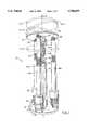
- FIG. 1is a perspective view of an extendible wrist mechanism made in accordance with one aspect of this invention
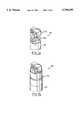
- FIG. lais a perspective fragmentary view of an alternate embodiment for the mechanism of FIG. 1,
- FIG. 1bis a perspective fragmentary view of a further alternate embodiment for the mechanism of FIG. 1,
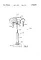
- FIG. 2is a partial perspective view of an extendible wrist mechanism made in accordance with another aspect of this invention.
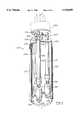
- FIG. 3is a partially sectioned perspective view of an extendible wrist mechanism made in accordance with a further aspect of this invention.
- FIG. 3ais a fragmentary side view of a portion of FIG. 3.
- an extendible wrist mechanism indicated generally at 10comprises a base 12 and an end plate 14.
- Three linear actuators 16a, 16b, and 16care disposed about a central axis C directed from the base to the end plate.
- Each linear actuatorcomprises a motor 22 and a ball screw 24.
- Linear actuators 16a, 16b, 16care an "off-the-shelf" item and will be well-understood to those skilled in the art.
- the motor 22 of each linear actuatoris mounted by a universal joint in the nature of U-joint 26 to base 12.
- Each U-jointis oriented such that it has a pivot axis R radially extending from axis C and a pivot axis P perpendicular to radial axis R.
- each U-jointpermits the end 29 of a linear actuator to pivot radially toward and away from axis C and also permits end 29 of each actuator to pivot tangentially with respect to a notional circle centered at axis C.
- End 29 of each linear actuatoris mounted to end plate 14 by a spherical joint 28 comprising a ball 30 received within a corresponding socket in end plate 14.
- An extendible means indicated generally at 32comprises a tube 34 extending rigidly from base 12 along axis C. The tube has internal splines 36.
- a shaft 38 with splines 40is telescopingly received within tube 34.
- Shaft 38terminates in a universal joint comprising U-joint 42 between the shaft 38 and end plate 14. It will be noted that the pivot centers of joints 28 and 42 lie in a common plane.
- An end effector(not shown) may be mounted to end plate 14 and base 12 may be mounted to the end of a robot arm.
- linear actuator 16cis operated to extend its ball screw at a faster rate than that of linear actuator 16a and 16b, or the latter linear actuators remain dormant or are operated in the opposite direction, then end plate 14 will be canted toward position 14-3.
- each spherical joint 28is a three degree of freedom joint, the spherical joints of the linear actuators allow the plate to cant.
- the U-joints 26 of the linear actuatorsallow these actuators to tilt radially inwardly toward axis C and to tilt about their radial axes R to accommodate the effective lateral foreshortening of the end plate.
- varying pitch and yaw combinations for the end platemay be achieved such as, for example, position 14-4 indicated in FIG. 1 for the end plate.
- the extendible means 32prevents rotation of end plate 14 with respect to the base during operation, as follows.
- U-joint 42has two degrees of freedom, in pitch and yaw, which permits canting of the end plate while preventing rotation of the end plate with respect to shaft 38.
- the splined connection between shaft 38 and tube 34prevents rotation of shaft 38 within tube 34. Therefore, since tube 34 is rigidly joined to base 12, the end plate cannot rotate with respect to the base.
- the U-joints 26are positioned so that the linear actuators are equally angularly spaced about axis C, 120 degrees apart from each other. This symmetrical arrangement optimizes the strength of the wrist mechanism for use when there are no operational restrictions for the orientations which will be assumed by end plate 14. However, other angular spacings between the linear actuators will provide a functioning mechanism. It is also preferred that the U-joint 42 of the extendible means be centered at axis C in order to simplify the kinematics of the mechanism 10.
- a spherical jointis a convenient inexpensive joint between the linear actuators and the end plate
- other three degree of freedom jointsare possible.
- three degree of freedom joint 58may be substituted.
- This jointcomprises a torsional joint, in the nature of a spring 60, affixed to a linear actuator 16, and a universal joint, in the nature of U-joint 62, affixed to the spring.
- the torsional joint of three degree of freedom joint 68comprises a flexural pivot 70.
- the structure of a flexural pivotwill be well understood by those skilled in the art and is described in U.S. Pat. No.
- U-joints 26could be replaced with clevis mounts each oriented to allow rotation of end 29 of an actuator about pivot axes P and the requisite tangential freedom provided by installing the clevis mounts on a modestly compliant footing.
- the needed tangential freedomcould be obtained by providing each pair of clevis mounts with spring loaded bearings to support pivot pins which extend from the linear actuator.
- any linear actuatorsuch as a roller screw or acme screw linear actuator, will suffice.
- any tool holdermay be attached to end plate 14 of extendible wrist mechanism 10.
- FIG. 2which illustrates an alternate embodiment of the invention, similarly to extendible wrist mechanism 10 of FIG. 1, mechanism 100 has a base 112 and an end member 114 with three linear actuators 116a, 116b, and 116c disposed about a central axis C' and joined to the end member 114 by spherical joints 128.
- Extendible meanscomprising a tube 134, is joined by a universal joint 180 to base 112 at central axis C'.
- the universal joint 180comprises a two degree of freedom pivoting U-joint.
- the universal joint 180provides the extendible means with a small amount of freedom to decline with respect to central axis C' which permits the end member 114 to be displaced transversely of axis C'.
- the required declinational freedomdepends upon the geometry of mechanism 100 but is typically between one and two degrees.
- the tube 134is slidingly keyed to shaft 138 and shaft 138 terminates in a universal joint in the nature of U-joint 142 joining shaft 138 to end member 114. Because of extension 182 of end member 114, it will be noted that the pivot centers of joints 128 lie in a plane above that of the pivot center of joint 142.
- the operation of the wrist mechanism 100 of FIG. 2is identical to that of mechanism 10 of FIG. 1 except that, because the pivot centers of joints 128 are not in the same plane as the pivot center of joint 142, extendible means 132 will decline by a small amount from axis C' as the end member 114 is canted. Universal joint 180 permits this declination while preventing rotation of the base plate 112 with respect to the end member 114.
- FIG. 3which illustrates a further alternate extendible wrist mechanism 200
- three linear actuators 216a, 216b, and 216care disposed about a central axis C" extending between base 212 and end plate 214.
- Clevis mounts 226extending from the motor 222 of each linear actuator receive pins extending from ears 294 of base 212 so as to permit the linear actuators to pivot toward and away from central axis C".
- a pin 290 extending from an ear 294 of base 212is received within the eye 292 of each clevis mount 226 and a spring 296 compliantly supports the pin 290 within eye 292.
- An extendible means 232comprises a sleeve 252 which is mounted to base 212 and surrounds the linear actuators 222.
- Sleeve 252telescopingly receives sleeve 254.
- Key 256 in sleeve 254is received within a keyway of sleeve 252.
- Sleeve 254has an end cap 258 with a U-joint 242 joining the end cap 258 to end plate 214 at central axis C".
- the end caphas openings 259 through which the linear actuators 216a, 216b, 216c extend.
- An end effector 260is shown in phantom attached to end plate 214.
- the end effectormay include a powered "roll axis" to provide an additional degree of freedom to the mechanism; this additional degree of freedom is typical of robot wrists.
- mechanism 200 of FIG. 3Operation of mechanism 200 of FIG. 3 is similar to that of FIG. 1. More particularly, extension of the linear actuators will extend end plate 214 as sleeve 254 telescopes within sleeve 252.
- the extendible means 232has the effect of preventing rotation of end plate 214 with respect to base 212.
- the U-joints 250 between the linear actuators and the end plateprovide two degrees of freedom, in pitch and yaw, between the linear actuators and the end plate; the play along the length of the actuators and in the clevis mounts provides a limited rotational degree of freedom.
- Clevis mounts 226allow the linear actuators to tilt toward and away from central axis C", and to tilt tangentially with respect to a notional circle centered about axis C", as necessary when the effective lateral extent of the end plate 214 changes as it pitches an/or yaws.
- the openings 259 in the end cap 258are sized to allow this tilting of the actuators.
- U-joint 242 of the extendible means 232permits pitch and yaw of the end plate 214 about central axis C".
- the extendible wrist mechanisms of this inventionallow for extension and retraction of an end effector as well as pitch and yaw of the end effector.
- the mechanismsare of simple construction and, therefore, of relatively low cost manufacture.
- the mechanismsdo not allow roll of the end effector about central axis C (FIG. 1), C' (FIG. 2), or C" (FIG. 3). If roll is a required degree of freedom for the end effector, the aforenoted powered roll axis may be provided.
- pitch and yawmay be imparted to the end plate with a minimum of three linear actuators, four or more linear actuators could be employed.
- the end plateIf only one angular degree of freedom (yaw or pitch) is required for the end plate (in addition to its translational freedom), then only two linear actuators are required. However, the two linear actuators must be equally angularly spaced about the axis between the base and end plate so that the axis and the two linear actuators lie in a common plane. Further, the joint between the extendible means and the end plate will be a pivot joint oriented to permit tilting of the end plate in this common plane.
Landscapes
- Engineering & Computer Science (AREA)
- Robotics (AREA)
- Mechanical Engineering (AREA)
- Manipulator (AREA)
Abstract
Description
Claims (19)
Priority Applications (2)
| Application Number | Priority Date | Filing Date | Title |
|---|---|---|---|
| US08/417,699US5740699A (en) | 1995-04-06 | 1995-04-06 | Wrist joint which is longitudinally extendible |
| JP8119451AJPH0929681A (en) | 1995-04-06 | 1996-04-05 | Extendable list mechanism |
Applications Claiming Priority (1)
| Application Number | Priority Date | Filing Date | Title |
|---|---|---|---|
| US08/417,699US5740699A (en) | 1995-04-06 | 1995-04-06 | Wrist joint which is longitudinally extendible |
Publications (1)
| Publication Number | Publication Date |
|---|---|
| US5740699Atrue US5740699A (en) | 1998-04-21 |
Family
ID=23655050
Family Applications (1)
| Application Number | Title | Priority Date | Filing Date |
|---|---|---|---|
| US08/417,699Expired - LifetimeUS5740699A (en) | 1995-04-06 | 1995-04-06 | Wrist joint which is longitudinally extendible |
Country Status (2)
| Country | Link |
|---|---|
| US (1) | US5740699A (en) |
| JP (1) | JPH0929681A (en) |
Cited By (105)
| Publication number | Priority date | Publication date | Assignee | Title |
|---|---|---|---|---|
| US6022047A (en)* | 1994-09-09 | 2000-02-08 | Nsk Ltd. | Universal joint and a yoke therefor for a steering apparatus |
| US6145405A (en)* | 1994-03-02 | 2000-11-14 | Renishaw Plc | Coordinate positioning machine |
| US6244086B1 (en)* | 2000-02-14 | 2001-06-12 | Ultra Dent Tools | Hand tool alignment device and method |
| US6257957B1 (en)* | 1999-12-01 | 2001-07-10 | Gerber Coburn Optical Inc. | Tactile feedback system |
| US6325808B1 (en) | 1998-12-08 | 2001-12-04 | Advanced Realtime Control Systems, Inc. | Robotic system, docking station, and surgical tool for collaborative control in minimally invasive surgery |
| US20030005786A1 (en)* | 2001-07-05 | 2003-01-09 | Microdexterity Systems, Inc. | Parallel mechanism |
| US20030018323A1 (en)* | 2001-06-29 | 2003-01-23 | Intuitive Surgical, Inc. | Platform link wrist mechanism |
| EP1256414A3 (en)* | 2001-05-10 | 2003-04-23 | Fundacion Fatronik | Kinematic system for machine tool headstock |
| US20030101838A1 (en)* | 2001-11-30 | 2003-06-05 | Junichiro Shinozaki | Manipulation unit |
| US20030121350A1 (en)* | 2000-02-10 | 2003-07-03 | Hakan Hvittfeldt | Industrial robot device |
| US20030163206A1 (en)* | 2002-02-28 | 2003-08-28 | Honda Giken Kogyo Kabushiki Kaisha | Parallel linkage and artificial joint device using the same |
| US20030178882A1 (en)* | 2002-02-13 | 2003-09-25 | Schmitz Johann Burkhard | Back support structure |
| US6679455B2 (en)* | 2000-09-18 | 2004-01-20 | Snecma Moteurs | Pointing device and an onboard pointing system |
| US6703725B2 (en)* | 2000-11-06 | 2004-03-09 | Hitachi, Ltd. | Joint driving apparatus |
| US20040111113A1 (en)* | 2002-12-09 | 2004-06-10 | The University Of Tokyo | High-rigidity forceps tip assembly for active forceps and active forceps equipped with the same |
| US20040143876A1 (en)* | 1998-12-03 | 2004-07-22 | Fredrik Persson | Industrial robot |
| US20040253079A1 (en)* | 2003-06-11 | 2004-12-16 | Dan Sanchez | Surgical instrument with a universal wrist |
| WO2005046500A1 (en)* | 2003-11-14 | 2005-05-26 | Massimo Bergamasco | Remotely actuated robotic wrist |
| US20050271955A1 (en)* | 2004-06-03 | 2005-12-08 | Board Of Regents, The University Of Texas System | System and method for improvement of alignment and overlay for microlithography |
| US20050275251A1 (en)* | 2004-06-01 | 2005-12-15 | Molecular Imprints, Inc. | Compliant device for nano-scale manufacturing |
| US20050274219A1 (en)* | 2004-06-01 | 2005-12-15 | Molecular Imprints, Inc. | Method and system to control movement of a body for nano-scale manufacturing |
| US20050275311A1 (en)* | 2004-06-01 | 2005-12-15 | Molecular Imprints, Inc. | Compliant device for nano-scale manufacturing |
| US20060005657A1 (en)* | 2004-06-01 | 2006-01-12 | Molecular Imprints, Inc. | Method and system to control movement of a body for nano-scale manufacturing |
| US20060086516A1 (en)* | 2004-10-27 | 2006-04-27 | Pegasus Sewing Machine Mfg. Co., Ltd. | Articulated arm |
| ES2257949A1 (en)* | 2004-11-30 | 2006-08-01 | Fundacion Fatronix | Solar tracker used in production of electric energy, has central arms and other arms connected to fixed platform and movable platform by respective gyro joints |
| US20060241810A1 (en)* | 2005-04-20 | 2006-10-26 | Dan Zhang | High stiffness, high accuracy, parallel kinematic, three degree of freedom motion platform |
| WO2007017245A1 (en)* | 2005-08-11 | 2007-02-15 | Abb Patent Gmbh | Positioning arrangement for an object and device for holding a car body part using such a positioning arrangement |
| US20070239203A1 (en)* | 2002-12-06 | 2007-10-11 | Intuitive Surgical, Inc. | Flexible wrist for surgical tool |
| US20070287081A1 (en)* | 2004-06-03 | 2007-12-13 | Molecular Imprints, Inc. | Method for obtaining force combinations for template deformation using nullspace and methods optimization techniques |
| WO2008011970A3 (en)* | 2006-07-26 | 2008-03-20 | Zeiss Ind Messtechnik Gmbh | Movable workpiece support for a machine, and machining system comprising a corresponding workpiece support |
| US20080070481A1 (en)* | 2006-09-15 | 2008-03-20 | Nihon Micro Coating Co., Ltd. | Probe cleaner and cleaning method |
| WO2008020459A3 (en)* | 2006-08-18 | 2008-04-03 | Zen Technologies Ltd | A motion platform system |
| US20080078266A1 (en)* | 2006-09-29 | 2008-04-03 | Abb Patent Gmbh | Jig particularly for the positioning of articles |
| WO2008048708A2 (en) | 2006-04-11 | 2008-04-24 | Koninklijke Philips Electronics, N.V. | A device for positioning an ultrasound transducer inside a mr scanner |
| US20080103524A1 (en)* | 1996-11-22 | 2008-05-01 | Intuitive Surgical, Inc. | Rigidly-linked articulating wrist with decoupled motion transmission |
| US20080150465A1 (en)* | 2003-09-12 | 2008-06-26 | Tmsuk Co., Ltd. | Lower Half Body Module of Bipedal Walking Robot |
| US20080312668A1 (en)* | 1996-11-22 | 2008-12-18 | Intuitive Surgical, Inc. | Rigidly-linked articulating wrist with decoupled motion transmission |
| US20090084219A1 (en)* | 2007-09-10 | 2009-04-02 | Ross-Hime Designs, Inc. | Robotic manipulator |
| US20090084216A1 (en)* | 2007-09-28 | 2009-04-02 | Intuitive Surgical, Inc. | Multiaxis Counterbalance and Positioning System Using a Spatial Linkage |
| US20090099576A1 (en)* | 2002-01-16 | 2009-04-16 | Intuitive Surgical, Inc. | Minimally invasive surgical training using robotics and telecollaboration |
| US20090248040A1 (en)* | 2008-03-31 | 2009-10-01 | Intuitive Surgical, Inc. | Coupler to Transfer Controller Motion from a Robotic Manipulator to an Attached Instrument |
| US20090248039A1 (en)* | 2008-03-31 | 2009-10-01 | Intuitive Surgical, Inc. | Sterile Drape Interface for Robotic Surgical Instrument |
| DE102008058644A1 (en)* | 2008-10-10 | 2010-04-15 | Num Industry Alliance Ag | cutter |
| US7785526B2 (en) | 2004-07-20 | 2010-08-31 | Molecular Imprints, Inc. | Imprint alignment method, system, and template |
| US20110071671A1 (en)* | 2009-09-22 | 2011-03-24 | Gm Global Technology Operations, Inc. | Dexterous humanoid robotic wrist |
| EP2301726A1 (en)* | 2009-09-24 | 2011-03-30 | CAMA 1 SpA | Telescopic shaft for an industrial robot according to the delta concept |
| US20110118709A1 (en)* | 2009-11-13 | 2011-05-19 | Intuitive Surgical Operations, Inc. | Surgical tool with a two degree of freedom wrist |
| US20110118707A1 (en)* | 2009-11-13 | 2011-05-19 | Intuititve Surgical Operations, Inc. | Wrist articulation by linked tension members |
| US20110118778A1 (en)* | 2009-11-13 | 2011-05-19 | Intuitive Surgical Operations, Inc. | End effector with redundant closing mechanisms |
| US20110137322A1 (en)* | 1998-11-20 | 2011-06-09 | Intuitive Surgical Operations | Cooperative Minimally Invasive Telesurgical System |
| US7982951B1 (en) | 2010-11-08 | 2011-07-19 | Robert Innes | Digital tracking platform for telescopes |
| US20110296944A1 (en)* | 2010-06-02 | 2011-12-08 | Disney Enterprises, Inc. | Three-axis robotic joint using four-bar linkages to drive differential side gears |
| US20120118097A1 (en)* | 2009-08-04 | 2012-05-17 | Majatronic Gmbh | Parallel Robot |
| CN102501246A (en)* | 2011-11-08 | 2012-06-20 | 北京邮电大学 | Three-drive extensible dexterous mechanical arm |
| US20130031764A1 (en)* | 2011-08-03 | 2013-02-07 | The Boeing Company | Robot including telescopic assemblies for positioning an end effector |
| US8870900B2 (en) | 1999-11-09 | 2014-10-28 | Intuitive Surgical Operations, Inc. | Endoscopic beating-heart stabilizer and vessel occlusion fastener |
| US8911428B2 (en) | 2001-06-29 | 2014-12-16 | Intuitive Surgical Operations, Inc. | Apparatus for pitch and yaw rotation |
| US20150020365A1 (en)* | 2012-02-13 | 2015-01-22 | Cvut V Praze, Fakulta Strojni | Method for setting positions of manipulating arms on a frame |
| US9005112B2 (en) | 2001-06-29 | 2015-04-14 | Intuitive Surgical Operations, Inc. | Articulate and swapable endoscope for a surgical robot |
| DE102014203409A1 (en)* | 2014-02-25 | 2015-08-27 | Matuschek Meßtechnik GmbH | Apparatus and method for grinding workpieces, in particular welding electrodes |
| US9119654B2 (en) | 1998-11-20 | 2015-09-01 | Intuitive Surgical Operations, Inc. | Stabilizer for robotic beating-heart surgery |
| US9271798B2 (en) | 1998-11-20 | 2016-03-01 | Intuitive Surgical Operations, Inc. | Multi-user medical robotic system for collaboration or training in minimally invasive surgical procedures |
| WO2016123083A1 (en)* | 2015-01-30 | 2016-08-04 | Irobot Corporation | Robotic arm and wrist mechanisms |
| CN106102630A (en)* | 2014-03-07 | 2016-11-09 | 剑桥医疗机器人技术有限公司 | surgical arm |
| US9573237B2 (en) | 2012-08-31 | 2017-02-21 | Matuschek Messtechnik Gmbh | Device and method for grinding workpieces, in particular welding electrodes |
| US20170221376A1 (en)* | 2014-05-08 | 2017-08-03 | Universite Laval | Parallel mechanism with kinematically redundant actuation |
| US9763740B2 (en) | 2009-11-13 | 2017-09-19 | Intuitive Surgical Operations, Inc. | Motor interface for parallel drive shafts within an independently rotating member |
| DE102016004328A1 (en)* | 2016-04-13 | 2017-10-19 | Satisloh Ag | Tool spindle for a device for fine machining of optically effective surfaces on workpieces |
| WO2018036634A1 (en)* | 2016-08-26 | 2018-03-01 | Abb Schweiz Ag | A parallel kinematics robot with a telescopic shaft |
| US20180125594A1 (en)* | 2016-11-08 | 2018-05-10 | Covidien Lp | Surgical systems including adapter assemblies for interconnecting electromechanical surgical devices and end effectors |
| CN108274478A (en)* | 2018-04-09 | 2018-07-13 | 上海方立数码科技有限公司 | A kind of intellect service robot head rotating mechanism |
| CN108340353A (en)* | 2018-03-12 | 2018-07-31 | 武汉理工大学 | A kind of imitative wrist joint submissive milling robot in parallel |
| US20180222727A1 (en)* | 2015-07-30 | 2018-08-09 | Ihc Engineering Business Limited | Load Control Apparatus |
| US10221894B2 (en) | 2014-08-29 | 2019-03-05 | Ulterra Drilling Technologies, L.P. | Universal joint |
| DE102017120333A1 (en)* | 2017-09-05 | 2019-03-07 | Schaeffler Technologies AG & Co. KG | Workpiece spindle for a grinding machine |
| USD847240S1 (en)* | 2017-07-18 | 2019-04-30 | Mitsubishi Electric Corporation | Joint driving member for robot |
| USD847242S1 (en)* | 2017-07-18 | 2019-04-30 | Mitsubishi Electric Corporation | Joint driving member for robot |
| USD847239S1 (en)* | 2017-07-18 | 2019-04-30 | Mitsubishi Electric Corporation | Joint driving member for robot |
| USD847241S1 (en)* | 2017-07-18 | 2019-04-30 | Mitsubishi Electric Corporation | Joint driving member for robot |
| USD847238S1 (en)* | 2017-07-18 | 2019-04-30 | Mitsubishi Electric Corporation | Joint driving member for robot |
| USD847891S1 (en)* | 2017-07-12 | 2019-05-07 | Mitsubishi Electric Corporation | Powered exoskeleton |
| US10316895B2 (en) | 2015-06-30 | 2019-06-11 | Ulterra Drilling Technologies, L.P. | Universal joint |
| US10337261B2 (en) | 2015-09-18 | 2019-07-02 | Ulterra Drilling Technologies, L.P. | Universal joint |
| US10508493B2 (en) | 2015-07-24 | 2019-12-17 | Ulterra Drilling Technologies | Universal joint |
| US20200009746A1 (en)* | 2018-07-03 | 2020-01-09 | Swift Engineering, Inc. | Robotic forearms |
| US10619678B2 (en) | 2015-05-22 | 2020-04-14 | Ulterra Drilling Technologies, L.P. | Universal joint |
| USD882658S1 (en)* | 2018-03-29 | 2020-04-28 | Mitsubishi Electric Corporation | Joint driving member for robot |
| USD882657S1 (en)* | 2018-03-29 | 2020-04-28 | Mitsubishi Electric Corporation | Joint driving member for robot |
| USD882659S1 (en)* | 2018-03-29 | 2020-04-28 | Mitsubishi Electric Corporation | Joint driving member for robot |
| USD882656S1 (en)* | 2018-03-29 | 2020-04-28 | Mitsubishi Electric Corporation | Joint driving member for robot |
| USD891492S1 (en)* | 2018-04-18 | 2020-07-28 | Mitsubishi Electric Corporation | Motion assistance apparatus |
| USD892186S1 (en)* | 2018-04-18 | 2020-08-04 | Mitsubishi Electric Corporation | Motion assistance apparatus |
| EP3858559A1 (en)* | 2020-01-31 | 2021-08-04 | MBDA Deutschland GmbH | Alignment platform, sensor system, aircraft and method for operating an alignment platform |
| US20210331310A1 (en)* | 2020-04-28 | 2021-10-28 | Ubtech Robotics Corp Ltd | Neck mechanism for robot |
| US11292137B2 (en)* | 2018-06-12 | 2022-04-05 | Shimizu Corporation | End effector and member mounting method |
| US11291516B2 (en) | 2015-05-14 | 2022-04-05 | Cmr Surgical Limited | Torque sensing in a surgical robotic wrist |
| CN114375183A (en)* | 2019-07-15 | 2022-04-19 | 史赛克公司 | Robotic handheld surgical instrument system and method |
| US11318626B1 (en)* | 2018-03-02 | 2022-05-03 | Empower Robotics Corporation | Compliant joint for a robotic arm |
| US11338453B2 (en)* | 2016-11-24 | 2022-05-24 | Kawasaki Jukogyo Kabushiki Kaisha | Joint structure for robot |
| US11510747B2 (en) | 2017-05-25 | 2022-11-29 | Covidien Lp | Robotic surgical systems and drapes for covering components of robotic surgical systems |
| CN115812024A (en)* | 2021-07-12 | 2023-03-17 | 谷歌有限责任公司 | Robotic Attachment Actuation |
| CN117301114A (en)* | 2023-09-27 | 2023-12-29 | 深圳市优世界机器人有限公司 | A kind of wrist-arm structure and robot |
| US12029523B2 (en) | 2017-12-01 | 2024-07-09 | Covidien Lp | Drape management assembly for robotic surgical systems |
| DE102023126054A1 (en)* | 2023-09-26 | 2025-03-27 | Nanyang Technological University | Joint arrangement for a robot and robot with such a joint arrangement |
| WO2025128996A1 (en)* | 2023-12-15 | 2025-06-19 | Boston Dynamics, Inc. | Screw actuator, a robor comprising the screw actuator and a method |
Families Citing this family (6)
| Publication number | Priority date | Publication date | Assignee | Title |
|---|---|---|---|---|
| KR20000063254A (en)* | 2000-06-07 | 2000-11-06 | 송치훈 | Parallel Mechanism Structure for 2 Degrees of Freedom Control in 3D Space |
| JP2004291215A (en)* | 2003-03-28 | 2004-10-21 | Rikogaku Shinkokai | On-vehicle type and traveling type operation arm/hand device |
| JP5397856B2 (en)* | 2009-08-28 | 2014-01-22 | 国立大学法人東京工業大学 | 6 DOF parallel mechanism |
| WO2015136648A1 (en)* | 2014-03-12 | 2015-09-17 | 株式会社安川電機 | Parallel link mechanism, robot and assembly device |
| CN107838913B (en)* | 2017-10-17 | 2020-10-02 | 安徽工程大学 | An automatic rotating clamping device for an industrial robot |
| CN109649610B (en)* | 2018-12-05 | 2020-10-09 | 山东大学 | Adaptive parallel folding gripper and underwater pipeline robot |
Citations (13)
| Publication number | Priority date | Publication date | Assignee | Title |
|---|---|---|---|---|
| US3813089A (en)* | 1972-09-08 | 1974-05-28 | Bendix Corp | Eccentric flexural pivot |
| US4407625A (en)* | 1981-05-15 | 1983-10-04 | Westinghouse Electric Corp. | Multi-arm robot |
| US4729253A (en)* | 1986-01-21 | 1988-03-08 | Rosheim Mark E | Wrist actuator |
| US4737048A (en)* | 1987-06-29 | 1988-04-12 | Herrstrom Timothy J | Resilient sign post attachment |
| US4739241A (en)* | 1986-10-09 | 1988-04-19 | Georgia Tech Research Corporation | Spherical motor particularly adapted for robotics |
| US4790718A (en)* | 1985-03-27 | 1988-12-13 | The English Electric Company Plc | Manipulators |
| US4819496A (en)* | 1987-11-17 | 1989-04-11 | The United States Of America As Represented By The Secretary Of The Air Force | Six degrees of freedom micromanipulator |
| US4872363A (en)* | 1986-01-20 | 1989-10-10 | Doy Rosenthal | Electric positioning apparatus |
| US5053687A (en)* | 1988-03-21 | 1991-10-01 | Inria Institut National De Recherche En Information Et En Automotique | Articulated device, for use in particular in robotics |
| US5114300A (en)* | 1989-03-02 | 1992-05-19 | Wovenwire Corporation | Robotic apparatus |
| US5317952A (en)* | 1991-11-22 | 1994-06-07 | Kinetic Sciences Inc. | Tentacle-like manipulators with adjustable tension lines |
| US5354158A (en)* | 1989-09-01 | 1994-10-11 | Kearney & Trecker Corporation | Six axis machine tool |
| US5378282A (en)* | 1993-06-28 | 1995-01-03 | Pollard; Willard L. | Robotic tool manipulating apparatus |
- 1995
- 1995-04-06USUS08/417,699patent/US5740699A/ennot_activeExpired - Lifetime
- 1996
- 1996-04-05JPJP8119451Apatent/JPH0929681A/enactivePending
Patent Citations (13)
| Publication number | Priority date | Publication date | Assignee | Title |
|---|---|---|---|---|
| US3813089A (en)* | 1972-09-08 | 1974-05-28 | Bendix Corp | Eccentric flexural pivot |
| US4407625A (en)* | 1981-05-15 | 1983-10-04 | Westinghouse Electric Corp. | Multi-arm robot |
| US4790718A (en)* | 1985-03-27 | 1988-12-13 | The English Electric Company Plc | Manipulators |
| US4872363A (en)* | 1986-01-20 | 1989-10-10 | Doy Rosenthal | Electric positioning apparatus |
| US4729253A (en)* | 1986-01-21 | 1988-03-08 | Rosheim Mark E | Wrist actuator |
| US4739241A (en)* | 1986-10-09 | 1988-04-19 | Georgia Tech Research Corporation | Spherical motor particularly adapted for robotics |
| US4737048A (en)* | 1987-06-29 | 1988-04-12 | Herrstrom Timothy J | Resilient sign post attachment |
| US4819496A (en)* | 1987-11-17 | 1989-04-11 | The United States Of America As Represented By The Secretary Of The Air Force | Six degrees of freedom micromanipulator |
| US5053687A (en)* | 1988-03-21 | 1991-10-01 | Inria Institut National De Recherche En Information Et En Automotique | Articulated device, for use in particular in robotics |
| US5114300A (en)* | 1989-03-02 | 1992-05-19 | Wovenwire Corporation | Robotic apparatus |
| US5354158A (en)* | 1989-09-01 | 1994-10-11 | Kearney & Trecker Corporation | Six axis machine tool |
| US5317952A (en)* | 1991-11-22 | 1994-06-07 | Kinetic Sciences Inc. | Tentacle-like manipulators with adjustable tension lines |
| US5378282A (en)* | 1993-06-28 | 1995-01-03 | Pollard; Willard L. | Robotic tool manipulating apparatus |
Non-Patent Citations (2)
| Title |
|---|
| Pp. 1 to 4 of an article entitled "Modeling of a Parallel Wrist Mechanism With Actuator Redundancy" by V. Hayward and R. Kurtz, printed in Advances in Robot Kinematics published by Springer Verlag. |
| Pp. 1 to 4 of an article entitled Modeling of a Parallel Wrist Mechanism With Actuator Redundancy by V. Hayward and R. Kurtz, printed in Advances in Robot Kinematics published by Springer Verlag.* |
Cited By (240)
| Publication number | Priority date | Publication date | Assignee | Title |
|---|---|---|---|---|
| US6336375B1 (en) | 1994-03-02 | 2002-01-08 | Renishaw, Plc | Coordinate positioning machine |
| US6145405A (en)* | 1994-03-02 | 2000-11-14 | Renishaw Plc | Coordinate positioning machine |
| US6022047A (en)* | 1994-09-09 | 2000-02-08 | Nsk Ltd. | Universal joint and a yoke therefor for a steering apparatus |
| US20080312668A1 (en)* | 1996-11-22 | 2008-12-18 | Intuitive Surgical, Inc. | Rigidly-linked articulating wrist with decoupled motion transmission |
| US9402619B2 (en) | 1996-11-22 | 2016-08-02 | Intuitive Surgical Operation, Inc. | Rigidly-linked articulating wrist with decoupled motion transmission |
| US8845681B2 (en) | 1996-11-22 | 2014-09-30 | Intuitive Surgical Operations, Inc. | Rigidly-linked articulating wrist with decoupled motion transmission |
| US20100217284A1 (en)* | 1996-11-22 | 2010-08-26 | Intuitive Surgical Operations, Inc. | Rigidly-linked articulating wrist with decoupled motion transmission |
| US8292916B2 (en) | 1996-11-22 | 2012-10-23 | Intuitive Surgical Operations, Inc. | Rigidly-linked articulating wrist with decoupled motion transmission |
| USRE43049E1 (en) | 1996-11-22 | 2011-12-27 | Intuitive Surgical Operations, Inc. | Rigidly-linked articulating wrist with decoupled motion transmission |
| US20080103524A1 (en)* | 1996-11-22 | 2008-05-01 | Intuitive Surgical, Inc. | Rigidly-linked articulating wrist with decoupled motion transmission |
| US8241306B2 (en) | 1996-11-22 | 2012-08-14 | Intuitive Surgical Operations, Inc. | Rigidly-linked articulating wrist with decoupled motion transmission |
| US8489235B2 (en) | 1998-11-20 | 2013-07-16 | Intuitive Surgical Operations, Inc. | Cooperative minimally invasive telesurgical system |
| US9666101B2 (en) | 1998-11-20 | 2017-05-30 | Intuitive Surgical Operations, Inc. | Multi-user medical robotic system for collaboration or training in minimally invasive surgical procedures |
| US8666544B2 (en) | 1998-11-20 | 2014-03-04 | Intuitive Surgical Operations, Inc. | Cooperative minimally invasive telesurgical system |
| US20110137322A1 (en)* | 1998-11-20 | 2011-06-09 | Intuitive Surgical Operations | Cooperative Minimally Invasive Telesurgical System |
| US8504201B2 (en) | 1998-11-20 | 2013-08-06 | Intuitive Sugrical Operations, Inc. | Cooperative minimally invasive telesurgical system |
| US9271798B2 (en) | 1998-11-20 | 2016-03-01 | Intuitive Surgical Operations, Inc. | Multi-user medical robotic system for collaboration or training in minimally invasive surgical procedures |
| US9119654B2 (en) | 1998-11-20 | 2015-09-01 | Intuitive Surgical Operations, Inc. | Stabilizer for robotic beating-heart surgery |
| US9867671B2 (en) | 1998-11-20 | 2018-01-16 | Intuitive Surgical Operations, Inc. | Multi-user medical robotic system for collaboration or training in minimally invasive surgical procedures |
| US9636186B2 (en) | 1998-11-20 | 2017-05-02 | Intuitive Surgical Operations, Inc. | Multi-user medical robotic system for collaboration or training in minimally invasive surgical procedures |
| US8914150B2 (en) | 1998-11-20 | 2014-12-16 | Intuitive Surgical Operations, Inc. | Cooperative minimally invasive telesurgical system |
| US20040143876A1 (en)* | 1998-12-03 | 2004-07-22 | Fredrik Persson | Industrial robot |
| US7188544B2 (en)* | 1998-12-03 | 2007-03-13 | Abb Ab | Industrial robot |
| US6325808B1 (en) | 1998-12-08 | 2001-12-04 | Advanced Realtime Control Systems, Inc. | Robotic system, docking station, and surgical tool for collaborative control in minimally invasive surgery |
| US20110112571A1 (en)* | 1999-04-07 | 2011-05-12 | Intuitive Surgical Operations, Inc. | Rigidly-linked articulating wrist with decoupled motion transmission |
| US8870900B2 (en) | 1999-11-09 | 2014-10-28 | Intuitive Surgical Operations, Inc. | Endoscopic beating-heart stabilizer and vessel occlusion fastener |
| US6257957B1 (en)* | 1999-12-01 | 2001-07-10 | Gerber Coburn Optical Inc. | Tactile feedback system |
| US6766711B2 (en)* | 2000-02-10 | 2004-07-27 | Abb Ab | Industrial robot device |
| US20030121350A1 (en)* | 2000-02-10 | 2003-07-03 | Hakan Hvittfeldt | Industrial robot device |
| US6244086B1 (en)* | 2000-02-14 | 2001-06-12 | Ultra Dent Tools | Hand tool alignment device and method |
| US6679455B2 (en)* | 2000-09-18 | 2004-01-20 | Snecma Moteurs | Pointing device and an onboard pointing system |
| US6703725B2 (en)* | 2000-11-06 | 2004-03-09 | Hitachi, Ltd. | Joint driving apparatus |
| EP1256414A3 (en)* | 2001-05-10 | 2003-04-23 | Fundacion Fatronik | Kinematic system for machine tool headstock |
| ES2205970A1 (en)* | 2001-05-10 | 2004-05-01 | Fundacion Fatronik | Kinematic system for machine tool headstock |
| ES2205970B1 (en)* | 2001-05-10 | 2005-07-16 | Fundacion Fatronik | CINEMATIC SYSTEM FOR MACHINE HEAD. |
| US8911428B2 (en) | 2001-06-29 | 2014-12-16 | Intuitive Surgical Operations, Inc. | Apparatus for pitch and yaw rotation |
| US10506920B2 (en) | 2001-06-29 | 2019-12-17 | Intuitive Surgical Operations, Inc. | Articulate and swappable endoscope for a surgical robot |
| US9730572B2 (en) | 2001-06-29 | 2017-08-15 | Intuitive Surgical Operations, Inc. | Articulate and swappable endoscope for a surgical robot |
| US6699235B2 (en)* | 2001-06-29 | 2004-03-02 | Intuitive Surgical, Inc. | Platform link wrist mechanism |
| US20040162547A1 (en)* | 2001-06-29 | 2004-08-19 | Intuitive Surgical, Inc. | Platform link wrist mechanism |
| US10105128B2 (en) | 2001-06-29 | 2018-10-23 | Intuitive Surgical Operations, Inc. | Apparatus for pitch and yaw rotation |
| US20070156119A1 (en)* | 2001-06-29 | 2007-07-05 | Intuitive Surgical, Inc. | Platform link wrist mechanism |
| US7691098B2 (en) | 2001-06-29 | 2010-04-06 | Intuitive Surgical, Inc. | Platform link wrist mechanism |
| US11051794B2 (en) | 2001-06-29 | 2021-07-06 | Intuitive Surgical Operations, Inc. | Apparatus for pitch and yaw rotation |
| US7066926B2 (en)* | 2001-06-29 | 2006-06-27 | Intuitive Surgical Inc | Platform link wrist mechanism |
| US9005112B2 (en) | 2001-06-29 | 2015-04-14 | Intuitive Surgical Operations, Inc. | Articulate and swapable endoscope for a surgical robot |
| US9717486B2 (en) | 2001-06-29 | 2017-08-01 | Intuitive Surgical Operations, Inc. | Apparatus for pitch and yaw rotation |
| EP1408846A4 (en)* | 2001-06-29 | 2008-07-09 | Intuitive Surgical Inc | Platform link wrist mechanism |
| US20030018323A1 (en)* | 2001-06-29 | 2003-01-23 | Intuitive Surgical, Inc. | Platform link wrist mechanism |
| US20030005786A1 (en)* | 2001-07-05 | 2003-01-09 | Microdexterity Systems, Inc. | Parallel mechanism |
| WO2003004223A3 (en)* | 2001-07-05 | 2003-11-27 | Microdexterity Systems Inc | Parallel manipulator |
| US20030101838A1 (en)* | 2001-11-30 | 2003-06-05 | Junichiro Shinozaki | Manipulation unit |
| US6860169B2 (en)* | 2001-11-30 | 2005-03-01 | Seiko Epson Corporation | Manipulation unit |
| US9039681B2 (en) | 2002-01-16 | 2015-05-26 | Intuitive Surgical Operations, Inc. | Minimally invasive surgical training using robotics and telecollaboration |
| US9786203B2 (en) | 2002-01-16 | 2017-10-10 | Intuitive Surgical Operations, Inc. | Minimally invasive surgical training using robotics and telecollaboration |
| US20090099576A1 (en)* | 2002-01-16 | 2009-04-16 | Intuitive Surgical, Inc. | Minimally invasive surgical training using robotics and telecollaboration |
| US20030178882A1 (en)* | 2002-02-13 | 2003-09-25 | Schmitz Johann Burkhard | Back support structure |
| US20030163206A1 (en)* | 2002-02-28 | 2003-08-28 | Honda Giken Kogyo Kabushiki Kaisha | Parallel linkage and artificial joint device using the same |
| EP1340478A3 (en)* | 2002-02-28 | 2006-03-29 | Honda Giken Kogyo Kabushiki Kaisha | Parallel linkage and artificial joint device using the same |
| US8790243B2 (en) | 2002-12-06 | 2014-07-29 | Intuitive Surgical Operations, Inc. | Flexible wrist for surgical tool |
| US11633241B2 (en) | 2002-12-06 | 2023-04-25 | Intuitive Surgical Operations, Inc. | Flexible wrist for surgical tool |
| US8690908B2 (en) | 2002-12-06 | 2014-04-08 | Intuitive Surgical Operations, Inc. | Flexible wrist for surgical tool |
| US9585641B2 (en) | 2002-12-06 | 2017-03-07 | Intuitive Surgical Operations, Inc. | Flexible wrist for surgical tool |
| US9095317B2 (en) | 2002-12-06 | 2015-08-04 | Intuitive Surgical Operations, Inc. | Flexible wrist for surgical tool |
| US10524868B2 (en) | 2002-12-06 | 2020-01-07 | Intuitive Surgical Operations, Inc. | Flexible wrist for surgical tool |
| US7862580B2 (en)* | 2002-12-06 | 2011-01-04 | Intuitive Surgical Operations, Inc. | Flexible wrist for surgical tool |
| US20070239203A1 (en)* | 2002-12-06 | 2007-10-11 | Intuitive Surgical, Inc. | Flexible wrist for surgical tool |
| US8337521B2 (en) | 2002-12-06 | 2012-12-25 | Intuitive Surgical Operations, Inc. | Flexible wrist for surgical tool |
| US20110125166A1 (en)* | 2002-12-06 | 2011-05-26 | Intuitive Surgical Operations, Inc. | Flexible Wrist for Surgical Tool |
| US20040111113A1 (en)* | 2002-12-09 | 2004-06-10 | The University Of Tokyo | High-rigidity forceps tip assembly for active forceps and active forceps equipped with the same |
| US7273488B2 (en)* | 2002-12-09 | 2007-09-25 | The University Of Tokyo | High-rigidity forceps tip assembly for active forceps and active forceps equipped with the same |
| US20070066986A1 (en)* | 2003-06-11 | 2007-03-22 | Intuitive Surgical Inc. | Surgical instrument with a universal wrist |
| US7121781B2 (en) | 2003-06-11 | 2006-10-17 | Intuitive Surgical | Surgical instrument with a universal wrist |
| US20040253079A1 (en)* | 2003-06-11 | 2004-12-16 | Dan Sanchez | Surgical instrument with a universal wrist |
| US8864794B2 (en) | 2003-06-11 | 2014-10-21 | Intuitive Surgical Operations, Inc. | Surgical instrument with a universal wrist |
| US20080150465A1 (en)* | 2003-09-12 | 2008-06-26 | Tmsuk Co., Ltd. | Lower Half Body Module of Bipedal Walking Robot |
| US7498758B2 (en)* | 2003-09-12 | 2009-03-03 | Tmsuk Co., Ltd. | Lower half body module of bipedal walking robot |
| US20080196533A1 (en)* | 2003-11-14 | 2008-08-21 | Massimo Bergamasco | Remotely Actuated Robotic Wrist |
| WO2005046500A1 (en)* | 2003-11-14 | 2005-05-26 | Massimo Bergamasco | Remotely actuated robotic wrist |
| US7387508B2 (en) | 2004-06-01 | 2008-06-17 | Molecular Imprints Inc. | Compliant device for nano-scale manufacturing |
| US20050275251A1 (en)* | 2004-06-01 | 2005-12-15 | Molecular Imprints, Inc. | Compliant device for nano-scale manufacturing |
| US20110048160A1 (en)* | 2004-06-01 | 2011-03-03 | Molecular Imprints. Inc. | Method and System to Control Movement of a Body for Nano-Scale Manufacturing |
| US8387482B2 (en) | 2004-06-01 | 2013-03-05 | Molecular Imprints, Inc. | Method and system to control movement of a body for nano-scale manufacturing |
| US20050274219A1 (en)* | 2004-06-01 | 2005-12-15 | Molecular Imprints, Inc. | Method and system to control movement of a body for nano-scale manufacturing |
| US20050275311A1 (en)* | 2004-06-01 | 2005-12-15 | Molecular Imprints, Inc. | Compliant device for nano-scale manufacturing |
| US20060005657A1 (en)* | 2004-06-01 | 2006-01-12 | Molecular Imprints, Inc. | Method and system to control movement of a body for nano-scale manufacturing |
| WO2005119395A3 (en)* | 2004-06-01 | 2007-03-08 | Molecular Imprints Inc | Method and system to control movement of a body for nano-scale manufacturing |
| US20070287081A1 (en)* | 2004-06-03 | 2007-12-13 | Molecular Imprints, Inc. | Method for obtaining force combinations for template deformation using nullspace and methods optimization techniques |
| US20050271955A1 (en)* | 2004-06-03 | 2005-12-08 | Board Of Regents, The University Of Texas System | System and method for improvement of alignment and overlay for microlithography |
| US7768624B2 (en) | 2004-06-03 | 2010-08-03 | Board Of Regents, The University Of Texas System | Method for obtaining force combinations for template deformation using nullspace and methods optimization techniques |
| US7535549B2 (en) | 2004-06-03 | 2009-05-19 | Board Of Regents, University Of Texas System | System and method for improvement of alignment and overlay for microlithography |
| US7785526B2 (en) | 2004-07-20 | 2010-08-31 | Molecular Imprints, Inc. | Imprint alignment method, system, and template |
| US8366434B2 (en)* | 2004-07-20 | 2013-02-05 | Molecular Imprints, Inc. | Imprint alignment method, system and template |
| US20100278955A1 (en)* | 2004-07-20 | 2010-11-04 | Molecular Imprints, Inc. | Imprint Alignment Method, System and Template |
| US7536931B2 (en)* | 2004-10-27 | 2009-05-26 | Pegasus Sewing Machine Mfg. Co., Ltd. | Articulated arm |
| US20060086516A1 (en)* | 2004-10-27 | 2006-04-27 | Pegasus Sewing Machine Mfg. Co., Ltd. | Articulated arm |
| ES2257949B1 (en)* | 2004-11-30 | 2007-07-16 | Fundacion Fatronix | SOLAR FOLLOWER BASED ON PARALLEL KINEMATICS. |
| ES2257949A1 (en)* | 2004-11-30 | 2006-08-01 | Fundacion Fatronix | Solar tracker used in production of electric energy, has central arms and other arms connected to fixed platform and movable platform by respective gyro joints |
| US20060241810A1 (en)* | 2005-04-20 | 2006-10-26 | Dan Zhang | High stiffness, high accuracy, parallel kinematic, three degree of freedom motion platform |
| WO2007017245A1 (en)* | 2005-08-11 | 2007-02-15 | Abb Patent Gmbh | Positioning arrangement for an object and device for holding a car body part using such a positioning arrangement |
| CN101484084B (en)* | 2006-04-11 | 2012-08-29 | 皇家飞利浦电子股份有限公司 | Device for positioning an ultrasound transducer inside an MR scanner |
| WO2008048708A2 (en) | 2006-04-11 | 2008-04-24 | Koninklijke Philips Electronics, N.V. | A device for positioning an ultrasound transducer inside a mr scanner |
| US9526515B2 (en) | 2006-04-11 | 2016-12-27 | Koninklijke Philips N.V. | Device for positioning an ultrasound transducer inside a MR scanner |
| US20090069667A1 (en)* | 2006-04-11 | 2009-03-12 | Koninklijke Philips Electronics N. V. | Device for positioning an ultrasound transducer inside a mr scanner |
| WO2008048708A3 (en)* | 2006-04-11 | 2008-11-27 | Koninkl Philips Electronics Nv | A device for positioning an ultrasound transducer inside a mr scanner |
| US20170079673A1 (en)* | 2006-04-11 | 2017-03-23 | Koninklijke Philips N.V. | Device for positioning an ultrasound transducer inside a mr scanner |
| WO2008011970A3 (en)* | 2006-07-26 | 2008-03-20 | Zeiss Ind Messtechnik Gmbh | Movable workpiece support for a machine, and machining system comprising a corresponding workpiece support |
| AU2007285356B2 (en)* | 2006-08-18 | 2011-07-14 | Zen Technologies Ltd. | A motion platform system |
| WO2008020459A3 (en)* | 2006-08-18 | 2008-04-03 | Zen Technologies Ltd | A motion platform system |
| US8403673B2 (en) | 2006-08-18 | 2013-03-26 | Zen Technologies Ltd. | Motion platform system |
| US20100273132A1 (en)* | 2006-08-18 | 2010-10-28 | Zen Technologies Ltd. | Motion platform system |
| EP2057614A4 (en)* | 2006-08-18 | 2014-01-22 | Zen Technologies Ltd | MOBILE PLATFORM SYSTEM |
| US20080070481A1 (en)* | 2006-09-15 | 2008-03-20 | Nihon Micro Coating Co., Ltd. | Probe cleaner and cleaning method |
| US20080078266A1 (en)* | 2006-09-29 | 2008-04-03 | Abb Patent Gmbh | Jig particularly for the positioning of articles |
| US20090084219A1 (en)* | 2007-09-10 | 2009-04-02 | Ross-Hime Designs, Inc. | Robotic manipulator |
| US7677129B2 (en)* | 2007-09-28 | 2010-03-16 | Intuitive Surgical, Inc. | Multiaxis counterbalance and positioning system using a spatial linkage |
| US20100116082A1 (en)* | 2007-09-28 | 2010-05-13 | Intuitive Surgical, Inc. | Multiaxis Counterbalance and Positioning System Using a Spatial Linkage |
| US8342054B2 (en) | 2007-09-28 | 2013-01-01 | Intuitive Surgical Operations, Inc. | Multiaxis counterbalance and positioning system using a spatial linkage |
| US20090084216A1 (en)* | 2007-09-28 | 2009-04-02 | Intuitive Surgical, Inc. | Multiaxis Counterbalance and Positioning System Using a Spatial Linkage |
| US7886743B2 (en) | 2008-03-31 | 2011-02-15 | Intuitive Surgical Operations, Inc. | Sterile drape interface for robotic surgical instrument |
| KR20110008189A (en)* | 2008-03-31 | 2011-01-26 | 인튜어티브 서지컬 오퍼레이션즈 인코포레이티드 | Coupler for transferring controller motion from the robot manipulator to the attached instrument |
| WO2009123925A1 (en)* | 2008-03-31 | 2009-10-08 | Intuitive Surgical, Inc. | Sterile drape interface for robotic surgical instrument |
| US8220468B2 (en) | 2008-03-31 | 2012-07-17 | Intuitive Surgical Operations, Inc. | Sterile drape interface for robotic surgical instrument |
| US9333045B2 (en) | 2008-03-31 | 2016-05-10 | Intuitive Surgical Operations, Inc. | Method and means for transferring controller motion from a robotic manipulator to an attached instrument |
| WO2009123924A1 (en) | 2008-03-31 | 2009-10-08 | Intuitive Surgical, Inc. | Coupler to transfer controller motion from a robotic manipulator to an attached instrument |
| JP2011519731A (en)* | 2008-03-31 | 2011-07-14 | インテュイティブ サージカル オペレーションズ, インコーポレイテッド | Couplers that transfer controller motion from the robot manipulator to the fixture |
| US20090248039A1 (en)* | 2008-03-31 | 2009-10-01 | Intuitive Surgical, Inc. | Sterile Drape Interface for Robotic Surgical Instrument |
| KR101651627B1 (en) | 2008-03-31 | 2016-08-26 | 인튜어티브 서지컬 오퍼레이션즈 인코포레이티드 | Coupler to transfer controller motion from a robotic manipulator to an attached instrument |
| US8333755B2 (en) | 2008-03-31 | 2012-12-18 | Intuitive Surgical Operations, Inc. | Coupler to transfer controller motion from a robotic manipulator to an attached instrument |
| US20090248040A1 (en)* | 2008-03-31 | 2009-10-01 | Intuitive Surgical, Inc. | Coupler to Transfer Controller Motion from a Robotic Manipulator to an Attached Instrument |
| US20110168189A1 (en)* | 2008-03-31 | 2011-07-14 | Intuitive Surgical Operations, Inc. | Sterile drape interface for robotic surgical instrument |
| US9144467B2 (en) | 2008-03-31 | 2015-09-29 | Intuitive Surgical Operations, Inc. | Method and means for transferring controller motion from a robotic manipulator to an attached instrument |
| DE102008058644A1 (en)* | 2008-10-10 | 2010-04-15 | Num Industry Alliance Ag | cutter |
| US9840011B2 (en) | 2009-08-04 | 2017-12-12 | Hartmut Ilch | Parallel robot |
| US20120118097A1 (en)* | 2009-08-04 | 2012-05-17 | Majatronic Gmbh | Parallel Robot |
| US9370867B2 (en)* | 2009-08-04 | 2016-06-21 | Majatronic Gmbh | Parallel robot |
| US8498741B2 (en) | 2009-09-22 | 2013-07-30 | Gm Global Technology Operations | Dexterous humanoid robotic wrist |
| US20110071671A1 (en)* | 2009-09-22 | 2011-03-24 | Gm Global Technology Operations, Inc. | Dexterous humanoid robotic wrist |
| EP2301726A1 (en)* | 2009-09-24 | 2011-03-30 | CAMA 1 SpA | Telescopic shaft for an industrial robot according to the delta concept |
| US20110118778A1 (en)* | 2009-11-13 | 2011-05-19 | Intuitive Surgical Operations, Inc. | End effector with redundant closing mechanisms |
| US12114941B2 (en) | 2009-11-13 | 2024-10-15 | Intuitive Surgical Operations, Inc. | Wrist articulation by linked tension members |
| US11304768B2 (en) | 2009-11-13 | 2022-04-19 | Intuitive Surgical Operations, Inc. | Wrist articulation by linked tension members |
| US11090119B2 (en) | 2009-11-13 | 2021-08-17 | Intuitive Surgical Operations, Inc. | Surgical tool with a two degree of freedom wrist |
| EP2594222A3 (en)* | 2009-11-13 | 2016-11-23 | Intuitive Surgical Operations, Inc. | Surgical tool with a compact wrist |
| US10898188B2 (en) | 2009-11-13 | 2021-01-26 | Intuitive Surgical Operations, Inc. | End effector with redundant closing mechanisms |
| US20110118707A1 (en)* | 2009-11-13 | 2011-05-19 | Intuititve Surgical Operations, Inc. | Wrist articulation by linked tension members |
| US10835331B2 (en) | 2009-11-13 | 2020-11-17 | Intuitive Surgical Operations, Inc. | Wrist articulation by linked tension members |
| US10779896B2 (en) | 2009-11-13 | 2020-09-22 | Intuitive Surgical Operations, Inc. | Motor interface for parallel drive shafts within an independently rotating member |
| US20110118709A1 (en)* | 2009-11-13 | 2011-05-19 | Intuitive Surgical Operations, Inc. | Surgical tool with a two degree of freedom wrist |
| US11357572B2 (en) | 2009-11-13 | 2022-06-14 | Intuitive Surgical Operations, Inc. | Double universal joint |
| US8852174B2 (en) | 2009-11-13 | 2014-10-07 | Intuitive Surgical Operations, Inc. | Surgical tool with a two degree of freedom wrist |
| US9259275B2 (en)* | 2009-11-13 | 2016-02-16 | Intuitive Surgical Operations, Inc. | Wrist articulation by linked tension members |
| US9226761B2 (en) | 2009-11-13 | 2016-01-05 | Intuitive Surgical Operations, Inc. | End effector with redundant closing mechanisms |
| US11660152B2 (en) | 2009-11-13 | 2023-05-30 | Intuitive Surgical Operations, Inc. | Motor interface for parallel drive shafts within an independently rotating member |
| US11717290B2 (en) | 2009-11-13 | 2023-08-08 | Intuitive Surgical Operations, Inc. | End effector with redundant closing mechanisms |
| US8876857B2 (en) | 2009-11-13 | 2014-11-04 | Intuitive Surgical Operations, Inc. | End effector with redundant closing mechanisms |
| US10292767B2 (en) | 2009-11-13 | 2019-05-21 | Intuitive Surgical Operations, Inc. | Double universal joint |
| US9763740B2 (en) | 2009-11-13 | 2017-09-19 | Intuitive Surgical Operations, Inc. | Motor interface for parallel drive shafts within an independently rotating member |
| US9101381B2 (en)* | 2009-11-13 | 2015-08-11 | Intuitive Surgical Operations, Inc. | Double universal joint |
| US11744645B2 (en) | 2009-11-13 | 2023-09-05 | Intuitive Surgical Operations, Inc. | Surgical tool with a two degree of freedom wrist |
| US12082894B2 (en) | 2009-11-13 | 2024-09-10 | Intuitive Surgical Operations, Inc. | Motor interface for parallel drive shafts within an independently rotating member |
| EP3444075A1 (en)* | 2009-11-13 | 2019-02-20 | Intuitive Surgical Operations Inc. | Surgical tool with a compact wrist |
| US10206748B2 (en) | 2009-11-13 | 2019-02-19 | Intuitive Surgical Operations, Inc. | Wrist articulation by linked tension members |
| US10098635B2 (en) | 2009-11-13 | 2018-10-16 | Intuitive Surgical Operations, Inc. | End effector with redundant closing mechanisms |
| US10045823B2 (en) | 2009-11-13 | 2018-08-14 | Intuitive Surgical Operations, Inc. | Surgical tool with a two degree of freedom wrist |
| US8336420B2 (en)* | 2010-06-02 | 2012-12-25 | Disney Enterprises, Inc. | Three-axis robotic joint using four-bar linkages to drive differential side gears |
| US20110296944A1 (en)* | 2010-06-02 | 2011-12-08 | Disney Enterprises, Inc. | Three-axis robotic joint using four-bar linkages to drive differential side gears |
| US7982951B1 (en) | 2010-11-08 | 2011-07-19 | Robert Innes | Digital tracking platform for telescopes |
| US20130031764A1 (en)* | 2011-08-03 | 2013-02-07 | The Boeing Company | Robot including telescopic assemblies for positioning an end effector |
| US9764464B2 (en)* | 2011-08-03 | 2017-09-19 | The Boeing Company | Robot including telescopic assemblies for positioning an end effector |
| CN102501246A (en)* | 2011-11-08 | 2012-06-20 | 北京邮电大学 | Three-drive extensible dexterous mechanical arm |
| US9358646B2 (en)* | 2012-02-13 | 2016-06-07 | Cvut V Praze, Fakulta Strojni | Supporting structure for repositionable and reconfigurable manipulating arms |
| US20150020365A1 (en)* | 2012-02-13 | 2015-01-22 | Cvut V Praze, Fakulta Strojni | Method for setting positions of manipulating arms on a frame |
| US9573237B2 (en) | 2012-08-31 | 2017-02-21 | Matuschek Messtechnik Gmbh | Device and method for grinding workpieces, in particular welding electrodes |
| DE102014203409B4 (en)* | 2014-02-25 | 2017-08-24 | Matuschek Meßtechnik GmbH | Apparatus and method for grinding rigid metallic welding electrodes for resistance welding |
| DE102014203409A1 (en)* | 2014-02-25 | 2015-08-27 | Matuschek Meßtechnik GmbH | Apparatus and method for grinding workpieces, in particular welding electrodes |
| US9579770B2 (en) | 2014-02-25 | 2017-02-28 | Matuschek Messtechnik Gmbh | Device and method for grinding workpieces using a control unit |
| CN106102630B (en)* | 2014-03-07 | 2019-10-18 | Cmr外科有限公司 | surgical arm |
| CN106102630A (en)* | 2014-03-07 | 2016-11-09 | 剑桥医疗机器人技术有限公司 | surgical arm |
| US9937012B2 (en)* | 2014-03-07 | 2018-04-10 | Cmr Surgical Limited | Surgical arm |
| US12414825B2 (en) | 2014-03-07 | 2025-09-16 | Cmr Surgical Limited | Surgical arm |
| US20160361123A1 (en)* | 2014-03-07 | 2016-12-15 | Cambridge Medical Robotics Limited | Surgical arm |
| CN110680504B (en)* | 2014-03-07 | 2022-06-14 | Cmr外科有限公司 | Surgical arm |
| US11224488B2 (en) | 2014-03-07 | 2022-01-18 | Cmr Surgical Limited | Surgical arm |
| CN110680504A (en)* | 2014-03-07 | 2020-01-14 | Cmr外科有限公司 | surgical arm |
| US11077547B2 (en)* | 2014-05-08 | 2021-08-03 | Universite Laval | Parallel mechanism with kinematically redundant actuation |
| US20170221376A1 (en)* | 2014-05-08 | 2017-08-03 | Universite Laval | Parallel mechanism with kinematically redundant actuation |
| US10221894B2 (en) | 2014-08-29 | 2019-03-05 | Ulterra Drilling Technologies, L.P. | Universal joint |
| US10578197B2 (en) | 2015-01-30 | 2020-03-03 | Irobot Corporation | Robotic arm and wrist mechanisms |
| US20160221197A1 (en)* | 2015-01-30 | 2016-08-04 | Irobot Corporation | Robotic Arm and Wrist Mechanisms |
| US9845850B2 (en)* | 2015-01-30 | 2017-12-19 | Irobot Corporation | Robotic arm and wrist mechanisms |
| WO2016123083A1 (en)* | 2015-01-30 | 2016-08-04 | Irobot Corporation | Robotic arm and wrist mechanisms |
| US11291516B2 (en) | 2015-05-14 | 2022-04-05 | Cmr Surgical Limited | Torque sensing in a surgical robotic wrist |
| US11903668B2 (en) | 2015-05-14 | 2024-02-20 | Cmr Surgical Limited | Torque sensing in a surgical robotic wrist |
| US12364564B2 (en) | 2015-05-14 | 2025-07-22 | Cmr Surgical Limited | Torque sensing in a surgical robotic wrist |
| US10619678B2 (en) | 2015-05-22 | 2020-04-14 | Ulterra Drilling Technologies, L.P. | Universal joint |
| US10316895B2 (en) | 2015-06-30 | 2019-06-11 | Ulterra Drilling Technologies, L.P. | Universal joint |
| US10508493B2 (en) | 2015-07-24 | 2019-12-17 | Ulterra Drilling Technologies | Universal joint |
| US20180222727A1 (en)* | 2015-07-30 | 2018-08-09 | Ihc Engineering Business Limited | Load Control Apparatus |
| US10822206B2 (en)* | 2015-07-30 | 2020-11-03 | Ihc Engineering Business Limited | Load control apparatus and method for controlling movement of a suspended load |
| US10337261B2 (en) | 2015-09-18 | 2019-07-02 | Ulterra Drilling Technologies, L.P. | Universal joint |
| US11426837B2 (en) | 2016-04-13 | 2022-08-30 | Satisloh Ag. | Tool spindle for a device for fine machining of optically active surfaces on workpieces |
| DE102016004328A1 (en)* | 2016-04-13 | 2017-10-19 | Satisloh Ag | Tool spindle for a device for fine machining of optically effective surfaces on workpieces |
| WO2018036634A1 (en)* | 2016-08-26 | 2018-03-01 | Abb Schweiz Ag | A parallel kinematics robot with a telescopic shaft |
| US12064203B2 (en) | 2016-11-08 | 2024-08-20 | Covidien Lp | Surgical systems including adapter assemblies for interconnecting electromechanical surgical devices and end effectors |
| US20180125594A1 (en)* | 2016-11-08 | 2018-05-10 | Covidien Lp | Surgical systems including adapter assemblies for interconnecting electromechanical surgical devices and end effectors |
| US11116594B2 (en)* | 2016-11-08 | 2021-09-14 | Covidien Lp | Surgical systems including adapter assemblies for interconnecting electromechanical surgical devices and end effectors |
| US11338453B2 (en)* | 2016-11-24 | 2022-05-24 | Kawasaki Jukogyo Kabushiki Kaisha | Joint structure for robot |
| US11510747B2 (en) | 2017-05-25 | 2022-11-29 | Covidien Lp | Robotic surgical systems and drapes for covering components of robotic surgical systems |
| USD847891S1 (en)* | 2017-07-12 | 2019-05-07 | Mitsubishi Electric Corporation | Powered exoskeleton |
| USD847242S1 (en)* | 2017-07-18 | 2019-04-30 | Mitsubishi Electric Corporation | Joint driving member for robot |
| USD847238S1 (en)* | 2017-07-18 | 2019-04-30 | Mitsubishi Electric Corporation | Joint driving member for robot |
| USD847240S1 (en)* | 2017-07-18 | 2019-04-30 | Mitsubishi Electric Corporation | Joint driving member for robot |
| USD847239S1 (en)* | 2017-07-18 | 2019-04-30 | Mitsubishi Electric Corporation | Joint driving member for robot |
| USD847241S1 (en)* | 2017-07-18 | 2019-04-30 | Mitsubishi Electric Corporation | Joint driving member for robot |
| DE102017120333A1 (en)* | 2017-09-05 | 2019-03-07 | Schaeffler Technologies AG & Co. KG | Workpiece spindle for a grinding machine |
| US12029523B2 (en) | 2017-12-01 | 2024-07-09 | Covidien Lp | Drape management assembly for robotic surgical systems |
| US11318626B1 (en)* | 2018-03-02 | 2022-05-03 | Empower Robotics Corporation | Compliant joint for a robotic arm |
| CN108340353A (en)* | 2018-03-12 | 2018-07-31 | 武汉理工大学 | A kind of imitative wrist joint submissive milling robot in parallel |
| USD882656S1 (en)* | 2018-03-29 | 2020-04-28 | Mitsubishi Electric Corporation | Joint driving member for robot |
| USD882659S1 (en)* | 2018-03-29 | 2020-04-28 | Mitsubishi Electric Corporation | Joint driving member for robot |
| USD882657S1 (en)* | 2018-03-29 | 2020-04-28 | Mitsubishi Electric Corporation | Joint driving member for robot |
| USD882658S1 (en)* | 2018-03-29 | 2020-04-28 | Mitsubishi Electric Corporation | Joint driving member for robot |
| CN108274478A (en)* | 2018-04-09 | 2018-07-13 | 上海方立数码科技有限公司 | A kind of intellect service robot head rotating mechanism |
| USD892186S1 (en)* | 2018-04-18 | 2020-08-04 | Mitsubishi Electric Corporation | Motion assistance apparatus |
| USD891492S1 (en)* | 2018-04-18 | 2020-07-28 | Mitsubishi Electric Corporation | Motion assistance apparatus |
| US11292137B2 (en)* | 2018-06-12 | 2022-04-05 | Shimizu Corporation | End effector and member mounting method |
| US20200009746A1 (en)* | 2018-07-03 | 2020-01-09 | Swift Engineering, Inc. | Robotic forearms |
| CN114375183A (en)* | 2019-07-15 | 2022-04-19 | 史赛克公司 | Robotic handheld surgical instrument system and method |
| US12232744B2 (en) | 2019-07-15 | 2025-02-25 | Stryker Corporation | Robotic hand-held surgical instrument systems and methods |
| EP3858559A1 (en)* | 2020-01-31 | 2021-08-04 | MBDA Deutschland GmbH | Alignment platform, sensor system, aircraft and method for operating an alignment platform |
| US20210331310A1 (en)* | 2020-04-28 | 2021-10-28 | Ubtech Robotics Corp Ltd | Neck mechanism for robot |
| WO2021219036A1 (en)* | 2020-04-28 | 2021-11-04 | 深圳市优必选科技股份有限公司 | Neck mechanism of robot |
| US20240198541A1 (en)* | 2021-07-12 | 2024-06-20 | Google Llc | Robot appendage actuation |
| US12325121B2 (en)* | 2021-07-12 | 2025-06-10 | Google Llc | Robot appendage actuation |
| CN115812024A (en)* | 2021-07-12 | 2023-03-17 | 谷歌有限责任公司 | Robotic Attachment Actuation |
| DE102023126054A1 (en)* | 2023-09-26 | 2025-03-27 | Nanyang Technological University | Joint arrangement for a robot and robot with such a joint arrangement |
| DE102023126054B4 (en)* | 2023-09-26 | 2025-05-08 | Nanyang Technological University | Joint arrangement for a robot and robot with such a joint arrangement |
| CN117301114A (en)* | 2023-09-27 | 2023-12-29 | 深圳市优世界机器人有限公司 | A kind of wrist-arm structure and robot |
| WO2025128996A1 (en)* | 2023-12-15 | 2025-06-19 | Boston Dynamics, Inc. | Screw actuator, a robor comprising the screw actuator and a method |
Also Published As
| Publication number | Publication date |
|---|---|
| JPH0929681A (en) | 1997-02-04 |
Similar Documents
| Publication | Publication Date | Title |
|---|---|---|
| US5740699A (en) | Wrist joint which is longitudinally extendible | |
| US5243873A (en) | Two-axis motion mechanism | |
| EP0202206B1 (en) | Robot | |
| US6203438B1 (en) | Constant velocity joint | |
| US8047093B2 (en) | Parallel robot | |
| EP2535268A1 (en) | A method for relieving kinematic binding and oscillatory drive forces in a rotor head of a rotary-wing aircraft | |
| JPS5890492A (en) | Robot arm device with split ball type wrist manipulator | |
| CN1048079C (en) | steering column assembly | |
| US20080272728A1 (en) | Robotic joint | |
| US7823477B2 (en) | Setting device joint with a rotating wobbler | |
| US6540471B1 (en) | Device for relative displacement of two elements | |
| EP0666150A1 (en) | Wrist structure for articulated robots | |
| JPS6034518A (en) | Flexible joint | |
| US4516958A (en) | Flexible shaft coupling device | |
| JP2000126956A (en) | Parallel mechanism machine tool | |
| EP0361745A1 (en) | Universal joints | |
| BR102014010788A2 (en) | MULTI-FUNCTION TILT STEERING COLUMN | |
| JPS60146920A (en) | Synchronous rotary joint | |
| AU9232998A (en) | Feed shell positioning mechanism | |
| US3926012A (en) | Constant velocity universal joints | |
| JP4805301B2 (en) | Parallel mechanism | |
| JPH0453913Y2 (en) | ||
| JPS5871092A (en) | robot arm | |
| JP2867703B2 (en) | Wrist mechanism of articulated robot | |
| US20020177484A1 (en) | Pulley type constant velocity joint |
Legal Events
| Date | Code | Title | Description |
|---|---|---|---|
| AS | Assignment | Owner name:SPAR AEROSPACE LIMITED, ONTARIO Free format text:ASSIGNMENT OF ASSIGNORS INTEREST;ASSIGNORS:BALLANTYNE, WILLIAM JOHN;WALKER, BRUCE CLARKE;SAMJI, AL-AMYN;REEL/FRAME:007429/0227;SIGNING DATES FROM 19950328 TO 19950329 | |
| AS | Assignment | Owner name:BANK OF NOVA SCOTIA, THE, CANADA Free format text:SECURITY INTEREST;ASSIGNOR:SPAR AEROSPACE LIMITED;REEL/FRAME:008495/0439 Effective date:19970415 | |
| STCF | Information on status: patent grant | Free format text:PATENTED CASE | |
| CC | Certificate of correction | ||
| AS | Assignment | Owner name:MACDONALD DETTWILER SPACE AND ADVANCED ROBOTICS LT Free format text:ASSIGNMENT OF ASSIGNORS INTEREST;ASSIGNOR:SPAR AEROSPACE LIMITED;REEL/FRAME:010272/0708 Effective date:19990507 | |
| FPAY | Fee payment | Year of fee payment:4 | |
| FEPP | Fee payment procedure | Free format text:PAYOR NUMBER ASSIGNED (ORIGINAL EVENT CODE: ASPN); ENTITY STATUS OF PATENT OWNER: LARGE ENTITY | |
| FEPP | Fee payment procedure | Free format text:PAYOR NUMBER ASSIGNED (ORIGINAL EVENT CODE: ASPN); ENTITY STATUS OF PATENT OWNER: LARGE ENTITY Free format text:PAYER NUMBER DE-ASSIGNED (ORIGINAL EVENT CODE: RMPN); ENTITY STATUS OF PATENT OWNER: LARGE ENTITY | |
| FPAY | Fee payment | Year of fee payment:8 | |
| FPAY | Fee payment | Year of fee payment:12 | |
| AS | Assignment | Owner name:MACDONALD, DETTWILER AND ASSOCIATES INC., CANADA Free format text:CHANGE OF NAME;ASSIGNOR:MACDONALD DETTWILER SPACE AND ADVANCED ROBOTICS LTD.;REEL/FRAME:033721/0759 Effective date:20050425 |