US5738677A - Apparatus and method for performing eye surgery - Google Patents
Apparatus and method for performing eye surgeryDownload PDFInfo
- Publication number
- US5738677A US5738677AUS08/455,732US45573295AUS5738677AUS 5738677 AUS5738677 AUS 5738677AUS 45573295 AUS45573295 AUS 45573295AUS 5738677 AUS5738677 AUS 5738677A
- Authority
- US
- United States
- Prior art keywords
- lens
- probe
- laser
- eye
- nuclear material
- Prior art date
- Legal status (The legal status is an assumption and is not a legal conclusion. Google has not performed a legal analysis and makes no representation as to the accuracy of the status listed.)
- Expired - Fee Related
Links
Images


Classifications
- A—HUMAN NECESSITIES
- A61—MEDICAL OR VETERINARY SCIENCE; HYGIENE
- A61N—ELECTROTHERAPY; MAGNETOTHERAPY; RADIATION THERAPY; ULTRASOUND THERAPY
- A61N5/00—Radiation therapy
- A61N5/06—Radiation therapy using light
- G—PHYSICS
- G02—OPTICS
- G02B—OPTICAL ELEMENTS, SYSTEMS OR APPARATUS
- G02B6/00—Light guides; Structural details of arrangements comprising light guides and other optical elements, e.g. couplings
- G02B6/24—Coupling light guides
- G02B6/42—Coupling light guides with opto-electronic elements
- G02B6/4296—Coupling light guides with opto-electronic elements coupling with sources of high radiant energy, e.g. high power lasers, high temperature light sources
- A—HUMAN NECESSITIES
- A61—MEDICAL OR VETERINARY SCIENCE; HYGIENE
- A61F—FILTERS IMPLANTABLE INTO BLOOD VESSELS; PROSTHESES; DEVICES PROVIDING PATENCY TO, OR PREVENTING COLLAPSING OF, TUBULAR STRUCTURES OF THE BODY, e.g. STENTS; ORTHOPAEDIC, NURSING OR CONTRACEPTIVE DEVICES; FOMENTATION; TREATMENT OR PROTECTION OF EYES OR EARS; BANDAGES, DRESSINGS OR ABSORBENT PADS; FIRST-AID KITS
- A61F9/00—Methods or devices for treatment of the eyes; Devices for putting in contact-lenses; Devices to correct squinting; Apparatus to guide the blind; Protective devices for the eyes, carried on the body or in the hand
- A61F9/007—Methods or devices for eye surgery
- A61F9/008—Methods or devices for eye surgery using laser
- A61F9/00802—Methods or devices for eye surgery using laser for photoablation
- G—PHYSICS
- G02—OPTICS
- G02B—OPTICAL ELEMENTS, SYSTEMS OR APPARATUS
- G02B6/00—Light guides; Structural details of arrangements comprising light guides and other optical elements, e.g. couplings
- G02B6/24—Coupling light guides
- G02B6/241—Light guide terminations
- A—HUMAN NECESSITIES
- A61—MEDICAL OR VETERINARY SCIENCE; HYGIENE
- A61B—DIAGNOSIS; SURGERY; IDENTIFICATION
- A61B18/00—Surgical instruments, devices or methods for transferring non-mechanical forms of energy to or from the body
- A61B18/18—Surgical instruments, devices or methods for transferring non-mechanical forms of energy to or from the body by applying electromagnetic radiation, e.g. microwaves
- A61B18/20—Surgical instruments, devices or methods for transferring non-mechanical forms of energy to or from the body by applying electromagnetic radiation, e.g. microwaves using laser
- A61B18/22—Surgical instruments, devices or methods for transferring non-mechanical forms of energy to or from the body by applying electromagnetic radiation, e.g. microwaves using laser the beam being directed along or through a flexible conduit, e.g. an optical fibre; Couplings or hand-pieces therefor
- A61B18/26—Surgical instruments, devices or methods for transferring non-mechanical forms of energy to or from the body by applying electromagnetic radiation, e.g. microwaves using laser the beam being directed along or through a flexible conduit, e.g. an optical fibre; Couplings or hand-pieces therefor for producing a shock wave, e.g. laser lithotripsy
- A—HUMAN NECESSITIES
- A61—MEDICAL OR VETERINARY SCIENCE; HYGIENE
- A61B—DIAGNOSIS; SURGERY; IDENTIFICATION
- A61B18/00—Surgical instruments, devices or methods for transferring non-mechanical forms of energy to or from the body
- A61B2018/00005—Cooling or heating of the probe or tissue immediately surrounding the probe
- A61B2018/00011—Cooling or heating of the probe or tissue immediately surrounding the probe with fluids
- A61B2018/00029—Cooling or heating of the probe or tissue immediately surrounding the probe with fluids open
- A61B2018/00035—Cooling or heating of the probe or tissue immediately surrounding the probe with fluids open with return means
- A—HUMAN NECESSITIES
- A61—MEDICAL OR VETERINARY SCIENCE; HYGIENE
- A61F—FILTERS IMPLANTABLE INTO BLOOD VESSELS; PROSTHESES; DEVICES PROVIDING PATENCY TO, OR PREVENTING COLLAPSING OF, TUBULAR STRUCTURES OF THE BODY, e.g. STENTS; ORTHOPAEDIC, NURSING OR CONTRACEPTIVE DEVICES; FOMENTATION; TREATMENT OR PROTECTION OF EYES OR EARS; BANDAGES, DRESSINGS OR ABSORBENT PADS; FIRST-AID KITS
- A61F9/00—Methods or devices for treatment of the eyes; Devices for putting in contact-lenses; Devices to correct squinting; Apparatus to guide the blind; Protective devices for the eyes, carried on the body or in the hand
- A61F9/007—Methods or devices for eye surgery
- A61F9/008—Methods or devices for eye surgery using laser
- A61F2009/00861—Methods or devices for eye surgery using laser adapted for treatment at a particular location
- A61F2009/0087—Lens
- A—HUMAN NECESSITIES
- A61—MEDICAL OR VETERINARY SCIENCE; HYGIENE
- A61F—FILTERS IMPLANTABLE INTO BLOOD VESSELS; PROSTHESES; DEVICES PROVIDING PATENCY TO, OR PREVENTING COLLAPSING OF, TUBULAR STRUCTURES OF THE BODY, e.g. STENTS; ORTHOPAEDIC, NURSING OR CONTRACEPTIVE DEVICES; FOMENTATION; TREATMENT OR PROTECTION OF EYES OR EARS; BANDAGES, DRESSINGS OR ABSORBENT PADS; FIRST-AID KITS
- A61F9/00—Methods or devices for treatment of the eyes; Devices for putting in contact-lenses; Devices to correct squinting; Apparatus to guide the blind; Protective devices for the eyes, carried on the body or in the hand
- A61F9/007—Methods or devices for eye surgery
- A61F9/008—Methods or devices for eye surgery using laser
- A61F2009/00885—Methods or devices for eye surgery using laser for treating a particular disease
- A61F2009/00887—Cataract
- G—PHYSICS
- G02—OPTICS
- G02B—OPTICAL ELEMENTS, SYSTEMS OR APPARATUS
- G02B6/00—Light guides; Structural details of arrangements comprising light guides and other optical elements, e.g. couplings
- G02B6/24—Coupling light guides
- G02B6/36—Mechanical coupling means
- G02B6/38—Mechanical coupling means having fibre to fibre mating means
- G02B6/3807—Dismountable connectors, i.e. comprising plugs
- G02B6/3833—Details of mounting fibres in ferrules; Assembly methods; Manufacture
- G02B6/3863—Details of mounting fibres in ferrules; Assembly methods; Manufacture fabricated by using polishing techniques
Definitions
- the present inventionrelates generally to the field of laser probes for surgery. More specifically, the present invention relates to laser probes used in eye surgery and to surgical techniques for treating cataracts.
- ultrasonic devicesare used to remove the lens.
- ultrasonic energyis directed against the lens of the eye to separate the lens into large pieces which must be continuously broken down into smaller pieces before they can be removed.
- aspirationis provided through a coaxial aspiration port to attract large lens pieces to surface of the ultrasonic probe, and hold the lens pieces in place, so they can be broken down into smaller pieces by the ultrasonic waves. This process of attracting, and breaking the pieces of the lens is repeated until the pieces are small enough to fit through the aspiration port in the ultrasonic probe.
- the process of separating the lens into pieces, and breaking the pieces into smaller piecesrequires a high level of skill and is also very time consuming. Therefore an improved lens removal procedure is needed.
- cataractous lens tissueincluding hard nuclear material
- a laseroperating in a unique pulsed regime which simultaneously produces an acoustic (i.e., photo acoustic) effect and an ablative effect on the lens tissue.
- the ablative effectis limited to an ablation zone which generally corresponds in size to the diameter of the laser beam spot (typically no more than about 300 microns).
- the ablation zonetypically corresponds in size to the diameter of the laser beam spot (typically no more than about 300 microns).
- the ablationwill form a crater at that location.
- the acoustic effectis less confined.
- Acoustic energyin the form of shock waves generated during ablation by the pulsed laser energy, radiate beyond the ablation zone throughout an acoustic zone which may be many times the size of the ablation zone.
- shock wavescreate microfractures in the lens tissue, and effectively weaken the structure of the lens tissue, particularly the hard nuclear material.
- the microfractured tissueis significantly more reactive to the laser pulses than tissue which has not been microfractured.
- the microfractured lens tissuereadily disintegrates into small fragments.
- ablationerodes the lens tissue, resulting in a viscous milky fluid.
- emulsionincludes a substantially fluid suspension
- a laser surgery apparatusis used to perform the above-discussed phacoemulsification process.
- the apparatuscomprises an optical probe configured for insertion into the anterior chamber of an eye adjacent to the lens of the eye.
- An optical waveguideconnected to the probe, delivers optical radiation through the probe to the lens.
- An optical sourceproduces the optical radiation in the form of pulses. These pulses are at a repetition rate, wavelength and an optical energy selected to cause significant ablation-induced damage to the lens within an ablation zone, and significant acoustic-induced damage to the lens within an acoustic zone, with the acoustic zone being significantly larger in size than the ablation zone.
- the pulsespreferably have a repetition rate of 5-25 pulses per second, with an energy per pulse of 10-80 mJ and an energy density of about 35-70 J/cm 2 .
- the repetition rateis about 10 pulses per second
- the energy per pulseis about 35 mJ
- the energy densityis about 45 J/cm 2 .
- the wavelength of the optical radiationis preferably in the infrared region of the optical spectrum, and may be 2.94 microns, as produced by an Er:YAG laser.
- a further aspect of the inventionincludes a method of removing a lens of an eye.
- a probeis inserted into the anterior chamber of the eye, and pulses of laser radiation from the probe are directed onto nuclear material of the lens.
- the wavelength, repetition rate and pulse energy of the laser radiationsimultaneously ablate the lens within an ablation zone and generate shock waves which radiate from the location and propagate through the nuclear material to acoustically damage nuclear material within an acoustic zone that extends outside the ablation zone.
- the probeis moved such that the pulses of laser radiation are directed onto acoustically damaged material, whereby simultaneous ablation and shock wave generation readily transform the nuclear material into an emulsion.
- the methodalso includes aspirating the emulsion from the eye.
- Yet another aspect of the inventioncomprises a method of removing the lens of an eye in which lens tissue is microfractured by directing laser pulses onto the lens such that the lens is significantly more reactive to the pulses than prior to the microfracturing. Pulses are then directed onto the microfractured lens tissue.
- the pulses directed onto the microfractured tissuehave the same pulse parameters as the pulses used to microfracture the lens tissue.
- Still another aspect of the inventioninvolves a method of removing a lens of an eye by inserting an elongated laser probe through a primary incision in the eye, into the anterior chamber of the eye.
- a tip of the probeis positioned in proximity to the lens.
- Pulsed laser radiationis supplied to the probe, and the laser radiation is directed from the tip along a path to a location on the lens to emulsify lens tissue.
- An elongated aspiration probeis inserted through a side port incision in the eye, into the anterior chamber of the eye.
- a tip of the aspiration probeis positioned in proximity to the aforementioned location without occluding the pulsed laser radiation.
- Emulsified lens tissueis removed from the path of the laser radiation by drawing the lens tissue through the aspiration probe in a direction transverse to the path.
- the aspiration probeis used to mechanically stabilize the eye and prevent movement thereof while the pulsed laser radiation is directed on the aforesaid location.
- the aspiration probeis also used to manipulate intraocular tissue while the pulsed laser radiation is directed at such location.
- both probesmay be removed from the eye, and the aspiration probe may be inserted through the primary incision so as to retrieve small pieces of ablated or emulsified material from all "o'clock" positions within the anterior chamber of the eye, and to remove soft cortical remnants of cataract tissue, as well as to vacuum the internal surface of the lens capsule.
- a further aspect of the inventioninvolves an apparatus for removing a cataractous lens of an eye which comprises an elongated laser probe, configured for insertion into an anterior chamber of the eye.
- the probecomprises a focusing lens which is connected to a source of pulse laser energy.
- the focusing lenstightly focuses the laser energy to provide an energy density at a focal spot of at least tens of Joules per square centimeter.
- the tight focusingcauses the focal spot to be proximal to an output surface of the focusing lens, whereby the energy density rapidly decreases beyond the focal spot to avoid damage to the posterior capsule of the eye during removal of the lens.
- the pulse laser energyhas a repetition rate of about 5 to 25 pulses per second.
- the repetition rate at the aforementioned energy densitygenerates shock waves which radiate outwardly from the focal spot into nuclear cataractous lens tissue at an acoustic intensity sufficient to cause substantial acoustic damage to the nuclear cataractous lens tissue.
- the focusing lensis the forwardmost portion of the probe to permit the focusing lens to be placed directly against the cataractous lens.
- the focal spotis about 11/2 mm or less from the output surface of the lens, and the energy density at the focal spot is at least 35 Joules per square centimeter.
- FIG. 1is a diagram of a laser delivery apparatus used with the probe of the present invention.
- FIG. 1Ais an enlarged view in partial cross section of the laser coupling assembly of FIG. 1.
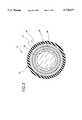
- FIG. 2is a cross-sectional view of an optical waveguide used with probe of the present invention, surrounded by a protective jacket.
- FIG. 3is a cross-sectional view of an alternate embodiment of the optical waveguide, surrounded by a protective jacket.
- FIG. 4is a diagram of a laser coupled to the coupling assembly of FIG. 1A.
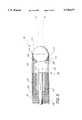
- FIG. 5is a view in partial cross section of one embodiment of the probe of the present invention which utilizes a micro-ball lens.
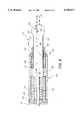
- FIG. 6is a view in partial cross section of another embodiment of the probe of the present invention which utilizes a silica fiber pigtail having an end formed in the shape of a micro-ball lens.
- FIG. 7is an illustration showing the probe attached to the handpiece of the apparatus of FIG. 1 and showing a tubing sleeve for delivering an irrigation fluid to the probe.
- FIG. 8is an enlarged view in partial cross section of the tubing sleeve and probe illustrated in FIG. 7.
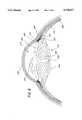
- FIG. 9is a cross-sectional view of the human eye.
- FIG. 10is an illustration of an eye undergoing the phacoemulsification procedure of the present invention.
- the present inventioncomprises an improved laser probe for eye surgery and improved surgical methods relating to emulsification of a cataractous lens.
- a medical laser delivery system 10comprises a handpiece 12, an optical waveguide 14 and an input coupling assembly 16 for attaching the waveguide 14 to a laser 17 (shown in FIG. 4).
- the handpiece 12has larger diameter than the waveguide 14 and is shaped so that it is easily manipulated by the hand of a user.
- the hand piece 12may possess ridges 18 on its exterior to secure a person's grip on the handpiece 12.
- the handpiece 12comprises a body portion 20, sized for grasping by the hand of a user, and a guide portion 22 which projects distally therefrom.
- the guide portion 22comprises a stainless steel tube through which a distal portion 24 of the waveguide 14 extends, and the guide portion 22 functions to provide rigidity to the distal end 24 of the waveguide 14.
- the distal end of the guide portion 22may be attached to a threaded housing so as to allow different embodiments of the improved laser probe of the present invention or other types of tips to be attached to the handpiece 12.
- the waveguide 14comprises a guiding structure 25 surrounded by a protective structure 26.
- the protective structure 26may be covered by an outer flexible sleeve or jacket 27.
- the guiding structure 25comprises a multimode optical fiber having an inner core 28 and an outer cladding 30.
- the core 28 and cladding 30are made of a fluoride-based material such a zirconium fluoride, aluminum fluoride, or hafnium fluoride.
- the core 28 and cladding 30are fluoride doped with impurities such that the cladding 30 has a lower index of refraction than the core 28.
- the refractive index of the core 28is 1.511 and the refractive index of the cladding 30 is 1.497.
- the guiding structureis manufactured using conventional optical fiber manufacturing techniques which are well known in the art.
- the protective structure 26 of the laser delivery systemcomprises a buffer material which is highly transmissive to infrared light, sufficiently strong to protect the fiber against breakage, flexible and moisture resistant.
- the preferred buffer materialcomprises a layer of thermoplastic polyimide having a thickness of 0.01 mm (such as PyralinTM, available from DuPont).
- the polyimidecomprises linear polymers having generally the imide group--CONCO--as part of the polymer chain.
- the polyimide buffer materialsurrounds and is bonded to the cladding 30 using conventional techniques.
- Polyimidehas a glass transition temperature of about 340° C., a tensile strength of about 19,000 psi, a thermal conductivity of about 0.00035 cal/(cm)(sec)(° C.), and an index of refraction of about 1.7 (e.g., 1.623). It has been found that, when used as a buffer for a fluoride-based fiber, polyimide dramatically increases the power handling capability of the fiber such that sustained transmission of infrared light having a wavelength of about 3 microns is possible at a power density of at least 4 kW/cm 2 over a fiber length of about 1 to 3 meters.
- the outer jacket 28, if used,may comprise PVC, polysulfone or other tubing material.
- the jacket 28is sized to fit over the protective structure 26 and slides thereon without being bonded thereto.
- FIG. 3A cross-sectional view of an alternative embodiment of the optical waveguide 14 is illustrated in FIG. 3.
- the alternative embodimentcomprises a double clad fiber 34 which comprises the core 28, surrounded by an inner cladding 36, which in turn is surrounded by an outer cladding 38.
- the double clad fiber 34is surrounded by the protective structure 26 and the jacket 28.
- the protective structure 26 of the preferred embodimentcomprises a layer of polyimide material, as described above, that has an index of refraction, higher than that of the claddings 36, 38.
- the outer cladding 38is provided to inhibit light propagating in leaky modes of the inner cladding 36 from reaching the polyimide protective structure 26, and the outer cladding 38 has a lower index of refraction than the inner cladding 36 for this purpose.
- the optical waveguide 14extends through the center of the handpiece 12 and emerges at the distal end 24, creating a path for laser light to travel through the handpiece 12 and out the distal end 24 to the tissue site T.
- the waveguide 14is protected from breakage at the point of entry to the handpiece 12 by a strain relief 40.
- the strain reliefis preferably made of PVC tubing.
- FIG. 1AA cross-sectional view of the input coupling assembly 16 is shown in FIG. 1A.
- the coupling assembly 16comprises a lock nut 42, a male fitting 44, a tubular sleeve 46 of IR grade silica and a strain relief 47.
- Both the male fitting 44 and the lock nut 42are made of stainless steel (i.e., an SMA-905 connector).
- the male fitting 44comprises a narrow tubular proximal end portion 48 which has a smaller diameter than a tubular distal portion 50.
- the exterior of the wider distal portion 50is partially threaded so that the lock nut 42 may be screwed over it.
- the inner diameter of the distal portion 50 of the fittingis approximately equal to the diameter of the waveguide 14 (including any outer jacket 28).
- the sleeve 46is located within the inner diameter of the narrow proximal end 48 of the mare fitting 44, and has a wall thickness which may be about 300% of the cladding thickness.
- the outer diameter of the sleeve 46is equal to the inner diameter of the fitting 44 in the proximal end portion 48. However, in the wide portion 50, the inner diameter of the fitting 44 becomes larger, leaving a recess 52 between the tubing 46 and the inner wall of the fitting 44.
- a proximal end portion of the waveguide 14is inserted into the sleeve 46. This portion has the jacket 28 (FIG. 2) and the polyimide buffer 26 removed, leaving only the guiding structure 25. The buffer 26 terminates at the inner end of the sleeve 46.
- the guiding structure 25is inserted within the sleeve 46, and the sleeve 46 is sized so that the guiding structure 25 is flush against the inner wall of the quartz sleeve 46 without intervening material such that it is not bonded to the sleeve 46.
- the waveguide 14is fastened to the sleeve 46 by epoxy glue 54 which is placed in the recess 42 between the inner wall of the fitting 44 and the waveguide 14.
- a proximal end 58 of the waveguide 14is cleaved or dry-polished with the sleeve 46 mounted thereon so that the input face formed by the sleeve and guiding structure is sufficiently smooth to prevent significant scattering of light as it enters the waveguide.
- the polishingis accomplished using 9 micron, 5 micron and 0.3 micron polishing paper.
- the polishingis accomplished "dry,” without water or by oil base polishing, since fluoride-based fibers have an affinity for water.
- FIG. 4illustrates the attachment of the coupling assembly 16 of the waveguide 14 to the laser 17.
- the laser 17comprises an infrared lasing medium 60 (e.g. a solid rod of Er:YAG) disposed between a rear reflector 61 and a front output coupler 63.
- the reflector 61reflects 99.5% of the light incident thereon while the output coupler 63 reflects about 90% of the light incident thereon to form a laser cavity.
- a beam combiner 65such as a dichromic mirror, is placed just outside the laser cavity to combine the invisible laser beam from the Er:YAG laser 17 with a visible aiming beam from a Helium Neon (HeNe) laser 67.
- HeNeHelium Neon
- the beam combiner 65transmits substantially all of the laser energy from the laser cavity and reflects substantially all of the energy from the HeNe laser 67 to form an output beam which is directed to a plano-convex focusing lens 62.
- the HeNe laser 67is within the visible spectrum and is used as an aiming beam to determine the location of the invisible infrared laser energy.
- the focusing lens 62focuses light from the beam combiner 65 for input to the coupling assembly 16.
- the laser medium 60 and the lens 62are contained within a chassis 64.
- the chassis 64has a female fitting 66 comprising a hole 68 having a slightly larger diameter than the narrow end 48 of the male fitting 44 to enable insertion of the narrow end 48 into the hole 68, and a threaded sleeve 70 having an inner diameter slightly larger than that of the hole 68, and an outer diameter sized to receive the lock nut 42 (FIG. 1A).
- the narrow end 48 of the male fitting 44is inserted into the hole 68, and the lock nut 42 is screwed onto the sleeve 70, thereby securing the male fitting 44 to the chassis 64.
- the axial length of the sleeve 70 and thickness of the chassis 64are such that the proximal end 58 of the waveguide 14 projects slightly past the interior surface of the chassis 64.
- the laser cavityemits a laser beam 72 which propagates through the beam combiner 65 and combines with the beam from the HeNe laser 67.
- the combined beamis transferred to the lens 62 and is focused at a focal point 74.
- the end 58 of the optical waveguide 14is located just past the focal length f of the lens.
- the focusing of the laser beam 72will produce a small beam spot on the end 58 of the waveguide 14. It is desirable that the laser beam's spot diameter be incident within 80% of core 28 to minimize the amount of the laser light incident on the sleeve 46 of the coupling 16.
- the positioning of the waveguide 14 in relation to the focal length f of the lensis important to insure that the infrared laser beam spot be incident within 80% of the core 28.
- the diameter of the beam spot at the focal point 74is a function of the focal length f of the lens 62 and the divergence angle of the laser beam 72.
- One embodiment of the inventionuses a lens with a 15 mm focal length f.
- the energy distribution within the spotis a function of the modes of the laser cavity.
- the TEM 00 mode of the laser cavityis the lowest order mode. It has an intensity distribution which follows a gaussian curve so that the peak energy is located at the center of the beam. The TEM 00 mode is therefore desirable because it produces maximum intensity at the center of the beam spot.
- a restricting aperture 76is placed in the path of the beam 72 inside the laser cavity between the laser medium 60 and the output coupler 63.
- the numerical aperture (N.A.) of the guiding structure for the TEM 00 modeis the sine of the maximum acceptance half angle within which light entering the core 28 will undergo total internal reflection and therefore remain within the core 28.
- the N.A. of the fiberis found by the equation: ##EQU1## where n 1 is the refractive index of the core 28 and n 2 is the refractive index of the cladding 30.
- the N.A. of the laser beam 72 entering the core 28is equal to the beam diameter before entering the lens 62 divided by twice the focal length of the lens.
- the numerical aperture of the waveguide 14be greater than the numerical aperture of the beam 72; or stated another way, that the convergence angle A of the beam 72 be less than the acceptance angle B of the waveguide 14.
- the restricting aperture 76additionally serves to reduce beam divergence and to keep the beam diameter within the limits needed to produce a numerical aperture within that of the guiding structure 25.
- the multimode laser beam 72is restricted by the aperture 76 to produce the TEM 00 mode, and focused by the lens 62 onto the end 58 of the fiber core 28 (FIG. 2).
- the lighttravels through the waveguide 14 to the distal end 24 where it may be further focused by a lens 62 or directly transmitted to the tissue site.
- the physician performing a surgical operationholds the handpiece 12 to direct the laser beam 72 to the desired target location T.
- the waveguide 14is capable of transmitting light having high power densities, at least 4 kilowatts per square centimeter at a wavelength of about 3.0 microns (2.94 ⁇ m for Er:YAG).
- the laser 17is a pulsed Er:YAG laser which produces pulses having a pulse duration of 250 ⁇ sec to 300 ⁇ sec. Each pulse is comprised of a train or burst of sub-pulses, each having a duration of about 200 nsec.
- the laser energy from the medical laser delivery system described aboveis delivered to the improved laser probe of the present invention.
- a small lens systemsuch as a micro-ball lens having a short focal length, is used to focus the laser energy to deliver the precise small spot diameter of high density laser energy.
- the waveguide 14 in this embodimentcomprises a fluoride based optical fiber 100 which extends from the laser source 17 to the handpiece 12 of the laser delivery system described above (FIGS. 1-4), and exits the guide portion 22.
- the guide portion 22for example may be formed of a piece of stainless steel tubing, henceforth referred to as hypo-tubing.
- a brass ferule housing 102is used to attach the laser probe 99 to the guide portion 22.
- the brass ferule housing 102comprises a proximal portion 104 and a distal portion 106.
- the proximal portion 104is threaded into the distal portion 106 to attach the two pieces.
- the proximal portion 104 of the brass ferule housing 102is placed inside the distal end 24 of the guide portion 22 and the two pieces are attached together at a crimp 107 using conventional crimping techniques.
- the proximal portion 104 of the brass ferule housing 102maintains the alignment of the fluoride fiber 100 within the brass ferule housing 102 using a fiber alignment sleeve 118.
- the distal portion 106 of the brass ferule housing 102comprises a hemispherical lens holder 108 which comprises stops designed to position and hold a micro-ball lens 110.
- the micro-ball lens 110is preferably a sapphire lens, an IR Quartz ball lens or a silica micro-sphere.
- the laser energy from the fluoride fiber 100will be transmitted from the exposed end 112 of the fluoride fiber 100 through an air gap 114 of 1 mm within the brass ferule housing 102 to the micro-ball lens 110 where it is focused to the desired spot size before transmission out of the probe 99.
- the micro-ball lens 110is epoxied into place in the hemispherical lens holder 108 against the stops using U.V.
- cured or 5 minute epoxy 116to fill in the space between the micro-ball lens 110 and the walls 111 of the hemispherical lens holder 108.
- the proximal portion 104 of the brass ferule housing 102is threaded into the distal portion 106 of the brass ferule housing 102, thereby aligning the micro-ball lens 110 with the fluoride fiber 100.
- An airtight sealing of both portions of the brass housing 102is maintained to prevent fluid or other debris from leaking into the housing 102 and damaging the fluoride fiber 100 or blocking the path of the laser energy.
- a short fiber 120is connected to one end of the fluoride based fiber 100.
- the fluoride based fiber 100is preferred for transmitting IR laser energy with an approximate wavelength of 3 microns, such as Er:YAG laser energy, over long distances.
- the fluoride fiber 100is toxic and has a low melting temperature which causes the fluoride fiber 100 to melt when it comes into contact with lased tissue debris.
- the fiber 120is comprised of non-toxic material which and has a high melting point, such as low OH silica having a low water content (e.g., 1-2 ppm) or sapphire.
- the preferred embodimentcomprises a short silica pigtail 120 which is positioned at the end of a fluoride based optical fiber 100 to provide the delivery of the IR laser energy to the desired internal target of the eye.
- a distal end 122 of the silica fiber 120is melted to form a micro-ball shaped surface 124 to focus the laser energy to the desired small spot size.
- a 0.2 N.A. fluoride based optical fiber with a 200-400 ⁇ m diameter core 28(FIG. 2) is used to deliver the laser energy.
- a 400 ⁇ m diameter core 28is used.
- the fiber pigtail 120comprises a silica low-OH 0.2 N.A.
- the silica fiberhas a 800-1000 ⁇ m diameter core 121 surrounded by a 40-50 ⁇ m thick cladding layer 123 on all sides, which is easily optically coupled to the preferred 400 ⁇ m diameter core 28 of the fluoride fiber 100.
- a brass ferule housing 126similar to the housing described above, is used to align the silica fiber pigtail 120 with the fluoride fiber 100.
- the brass ferule housing 126comprises two pieces which are threaded together to align the two fibers, a first proximal piece 128 and a second distal piece 130.
- the proximal piece 128 of the brass ferule housing 126is threaded into the distal piece 130 to align the fibers.
- the proximal piece 128 of the brass ferule housing 126is placed within the distal end 24 of the guide portion 22 of the handpiece 12 (FIG. 1), and the two pieces are attached together at a crimp 127 using conventional crimping techniques.
- the guide portion 22such as a piece of hypo-tubing, guides the fluoride fiber 100 into the brass ferule housing 126 and maintains the position of the fluoride fiber 100 with respect to the handpiece 12.
- the fluoride fiber 100is placed in a fiber alignment sleeve 132, such as a piece of quartz tubing, to position the fluoride fiber 100 with respect to the silica fiber pig tail 120.
- the silica fiber pigtail 120is encased within a separate positioning structure 134, i.e. a piece of hypo-tubing.
- the positioning structure 134abuts a positioning flange 136 inside the distal piece 130 of the brass ferule housing 126, and extends along the length of the silica fiber pigtail 120 before terminating proximal to the micro-ball shaped surface 124 of the silica pigtail 120.
- the positioned structure 134protects and supports the silica fiber 120 as it extends from the distal piece 130 of the brass ferule housing 126.
- the silica fiber pigtail 120 and fluoride fiber 100are positioned to allow for a 1 mm air gap 138 between a distal end 140 of the fluoride fiber 100 and a proximal end 142 of the silica fiber pigtail 120 within the brass ferule housing 126.
- the air gap 138is provided to prevent the distal end 140 of the fluoride fiber 100 from breaking down over long periods of continuous lasing, approximately 2-7 minutes in duration at high pulse repetition rates.
- the fluoride fiber 100has a low melting temperature caused by its low glass transition temperature Tg, therefore it can not withstand elevated temperatures for long periods of time.
- the silica fiber pigtail 120is capable of transmitting up to 80% of the output laser energy from the fluoride fiber 100, and the remaining 20% or more of the energy is reflected, refracted and absorbed. The energy that is absorbed by the fibers 100, 120 eventually is converted into heat. The accumulation of excessive heat at the distal end 140 of the fluoride fiber 100 can cause the breakdown of the fluoride fiber 100.
- the preferred 1 mm air gap 138 between the fluoride fiber 100 and the silica fiber pigtail 120was chosen to reduce heat damage of the fluoride fiber 100 while still enabling the coupling of the fluoride fiber 100 with the preferred 400 ⁇ m diameter core 28 with the silica fiber pigtail 120 with the preferred 800-1000 ⁇ m diameter core 121, both fibers with a 0.2 N.A. acceptance angle.
- proximal or input end 142 of the silica fiber pigtail 120is preferably covered with an anti-reflective coating, such as MgF 2 at 2.94 microns, to minimize the amount of energy that is reflected from the proximal end 142 of the silica fiber pigtail 120 to the distal end 140 of the fluoride fiber 100, thereby further reducing the damage to the fluoride fiber 100.
- an anti-reflective coatingsuch as MgF 2 at 2.94 microns
- the silica fiber pigtail 120is manufactured by cutting a low-OH silica fiber using a fiber cleaver to 10-15 mm in length. Both ends of the cut fiber are successively polished with 15, 9, 3, and 0.3 ⁇ m polishing papers. Next, the U.V. acrylate jacket 27 is removed from the entire length of the silica fiber.
- the support structure 134such as hypotubing, is attached to the silica fiber 120 using epoxy 144
- the support structure 134 with the silica fiber 120 enclosedis attached to a wall 146 of the distal piece 130 of the brass ferule housing 126 using epoxy 144 to prevent any fluid or debris from entering the housing 126.
- the distal end 122 of the silica fiber 120is fused, or melted, by a fusion splicer to create the proper configuration of the micro-ball surface 124.
- the radius of the micro-ball surface 124is controlled by the amount of current applied by the fusion splicer as well as the duration of exposure to the current of the fusion splicer.
- the radius and the position of the focal point 150 of the micro-ball surface 124 of the silica fiber pigtail 120is calculated using Paraxial theory
- F1the focal length of the probe
- F2is the distance from a proximal focal point 154 to the center 152 of the micro-ball
- n2the refractive index of the micro-ball
- Rsis the radius of the micro-ball 124.
- FIGS. 5 and 6respectively are preferably used with the improved lens phacoemulsification procedure of the present invention.
- the improved lens phacoemulsification methodit is also desirable to coaxially deliver irrigation fluid with the laser energy.
- FIG. 7an embodiment of the laser delivery system of FIG. 1 is coupled to a fluid delivery supply. Fluid 192 from the fluid supply is propelled by a pump which is controlled by a foot switch (not shown).
- a fitting 196 with an entrance port 197 and an exit port 198is attached over the handpiece 12 and extends just past the exit point of the guide support 22 from the handpiece 12.
- a flexible plastic tubing 191extends from a fluid supply into the entrance port 197 of the fitting 196.
- the fitting 196is provided to seal the fluid 192 within the space between the fitting 196 and the exterior walls of the handpiece 12.
- a first piece of PVC tubing 193overlaps the exit port 198 of the fitting 196 and extends coaxial to the guide support 22 and terminates at the proximal piece 128 of the brass ferule housing 126.
- the userselects an embodiment of the laser probe that is desired, and slips a second piece of PVC tubing 195 coaxially over the probe.
- the probeis connected to the guide support 22 by engaging the threads on the proximal piece 128 and distal piece 130 of the brass ferule housing 126.
- the second piece of PVC tubing 195 that is located coaxial to the laser probeis positioned to overlap the first piece of PVC tubing 193 coaxial to the brass ferule housing 126 thereby connecting the two pieces of tubing and forming a PVC sleeve 190.
- the fluid 192travels from the exit port 198 of the fitting 196 through the PVC sleeve 190 and is delivered coaxially with the laser energy.
- FIG. 8an enlarged view of the laser probe 119, as illustrated in FIGS. 6, is shown within the PVC thin walled sleeve 190.
- the fluid 192flows within an annular space 194 that is formed between the probe 119 and the PVC sleeve 190.
- the second piece of PVC tubing that forms the PVC sleeve 190terminates just before the microball surface 124 of the silica fiber pigtail to allow an outlet for the fluid at a distal end 195 of the PVC sleeve 190.
- the fluid upon exiting the PVC sleeveis delivered coaxially to the silica fiber pigtail 120 at the target location.
- the probe 99may be similarly adapted to provide coaxial delivery of fluid.
- a tough outer membrane known as the sclera 200surrounds all of the eye except the portion covered by the cornea 202, the thin transparent membrane which covers the iris 204. Outside the sclera 200 is a layer of tissue called conjunctiva 206. The cornea 202 merges with into the sclera 200 at a juncture referred to as the limbus 208.
- the ciliary body 210begins at the limbus 208 and extends along the interior of the sclera 200 and becomes the choroid 212.
- the choroid 212is the vascular membrane which extends along the retina (not shown) back towards the optic nerve (not shown).
- the anterior chamber 214 of the eyeis the space between the cornea 202 and the lens 216 of the eye which is filled with aqueous humor 218.
- the trabecular mesh work 220removes excess aqueous humor 218 from the anterior chamber 214 through Schlemm's canal 222 through veins which merge with blood carrying veins to take the aqueous 218 away from the eye.
- the crystalline lens 216 of the eyeis situated between the iris of the eye 204 and the vitreous body.
- the lens 216 of the eyeis enclosed in a transparent membrane called a lens capsule 224.
- the lens 216 of the eyeis a bi-convex lens that is slightly more concave on the anterior side of the lens.
- the lensis made up of an outer cortex 226, which is a softer tissue, and a firm central portion, or nucleus 228 of the lens. When a cataract forms, the nucleus 228 becomes quite dense and hard.
- a capsulotomyis performed to expose a portion of the lens 216 underlying the lens capsule 224.
- a preferred apparatus and method for performing a capsulotomyis discussed in co-pending application Ser. No. 680,815, filed Apr. 4, 1991, which is hereby incorporated by reference.
- the phacoemulsification procedureis performed using the probe 119 or the probe 99.
- the procedurewill be described in connection with the probe 119, however, it will be understood that the probe 99 may be utilized also.
- Two incisionsare made in either the sclera 200 or the cornea 202 of the eye to allow the entry of instruments into the anterior chamber 214.
- the laser probe 119 and coaxial PVC sleeve 190 illustrated in FIG. 11are introduced into the anterior chamber 214 through the primary incision 230.
- An aspiration probe 236comprising a 21-23 gauge needle connected to an aspirator is introduced into the anterior chamber 214 through the side port incision 232.
- the primary incision 234 and side-port incision 232can be made at any location around the circumference of the anterior chamber 214, or the circumference of the limbus 208.
- optical radiationis directed at the lens 216 of the eye through the laser probe 119 in the form of pulses.
- the pulsesare applied at a repetition rate, a wavelength and an optical energy to simultaneously ablate the lens 216 at the location where the pulses are applied, and to generate shock waves which radiate from the location where the pulses are applied through the nuclear material 228 of the lens 216 to acoustically damage the nuclear material 228 of the lens 216.
- the application of pulses at the repetition rate, wavelength and optical energy noted abovecause significant ablation-induced damage to the lens 216 and significant acoustic-induced damage to the lens 216, whereby the acoustic-induced damage is significantly more widespread than the ablation induced damage.
- the optical energy at the focal spotis sufficient to cut a crater in the cataractous nuclear material 228 of the lens.
- the ablation-induced damage of the lens 216is substantially within the focal spot region while the acoustic-induced damage radiates outwardly from the focal spot and into the nucleus 228 of the lens.
- the repetition ratemay be about 5-25 pulses per second, and in the preferred embodiment, the rate is 10 pulses per second.
- the energy of each pulsemay be about 10-80 mJ, and in the preferred embodiment, the energy of each pulse is about 35 mJ.
- the duration of each pulsemay be about 200 to 300 ⁇ sec, and in the preferred embodiment, is 250 ⁇ sec.
- the wavelength of the laser energy used in the preferred embodimentis in the infrared region of the optical spectrum at 2.94 microns.
- the spot size at the focal pointis between 250 and 350 microns in diameter, and the energy density at the focal spot is 35 to 70 J/cm 2 .
- the small spot diameterprovides the high energy densities that are required for the lens phacoemulsification procedure of the present invention.
- the optical probe 119generates a focal spot having a diameter of 300 microns with an energy density at the focal spot of about 45 J/cm 2 .
- the preferred focal length of the probe (F1)is from 1 to 2 mm and the radius of the micro-ball (RS) is about 0.7 mm, such that the working distance (WD) between the front end surface of the probe and the focal spot is 0.3 to 1.3 mm.
- the focal lengthis 1.5 mm, and the working distance (WD) is 0.8 mm.
- the short focal length of the probeenables delivery of the high density laser energy to the focal point, and causes the excess energy to diverge rapidly beyond the focal point.
- the energy output from the probediverges from its end in accordance with a numerical aperture (N.A.) of 0.2, and the focused energy beyond the focal point of the laser probe diverges in accordance with a numerical aperture in the range of 0.3-0.5.
- N.A.numerical aperture
- This rapid divergence beyond the focal pointis advantageous as it reduces the effect of the stray laser energy on the surrounding tissues of the eye that are not being lased, particularly the posterior capsule of the lens.
- the focal spot of the laser optical probe 119is initially positioned the anterior surface of the cortex of the lens.
- the soft cortex 226 of the lensquickly emulsifies in response to the laser pulses through ablation alone.
- dense, hard nuclear materialis encountered which is significantly less responsive to ablation than the cortex.
- the focal point of the probeis positioned proximal to epinuclear material, at a location which is substantially at the anterior surface of the nucleus (in some eyes about one-third the original thickness of the lens 216) to form a crater in the nucleus 228 of the lens.
- the pulses of the optical energygenerate shock waves in the lens 216 which radiate outwardly from the crater to cause micro-fractures in the cataractous nuclear material 228 of the lens, thereby causing the acoustically-induced damage outside the focal spot.
- the micro-fractured nuclear materialis sufficiently reactive to the pulses of optical energy to cause the nuclear material 228 to readily disintegrate upon exposure to the focal spot of the optical energy.
- the optical probe 119is moved along a path across the nuclear material 228 over the entire surface of the lens to "paint" the lens with the laser energy at a sufficiently slow rate to cause ablation of the lens material and form craters in the nucleus at multiple locations along the path.
- the ablationforcibly dislodges microscopic particles of lens tissue which produces the viscous milky fluid.
- the focal spot of the optical energyWhen the focal spot of the optical energy is placed on acoustically-damaged material, the lens material disintegrates into small fragments. In effect, the lens "falls apart,” creating fragments at least about an order of magnitude smaller in size than the original lens, and commonly no larger than the focal spot. These fragments mix with the milky fluid to form an emulsion which can be removed by aspiration through a 500 micron diameter aspiration probe.
- the laser probe 119is moved across the lens so as to prevent the lens from fracturing into large pieces. If the probe is held in a single location (e.g., at the middle of the lens) too long, the lens may divide into large pieces. If this occurs, the pieces may be held in a stable location by the aspiration probe, using the suction from the probe to draw the piece against the aspiration port in a manner similar to that used in ultrasonic emulsification techniques, and laser pulses are applied to emulsify each piece.
- the unemulsified portion of the lenswill remain as a unitary whole until the removal process is substantially completed. This procedure advantageously eliminates the need to manipulate multiple chunks of lens and enhances the efficiency of the lens removal technique.
- irrigation fluid 192is preferably constantly supplied through the primary incision 234 into the anterior chamber 214 of the eye to remove heat that may be generated during the emulsification process.
- the fluidflows through the annular area 194 between the coaxial PVC sleeve 190 and the probe 119.
- the fluid 192is preferably a Balanced Salt Solution (B.S.S.) which is close in composition to the solution Of the aqueous humor 218 of the eye.
- B.S.S.Balanced Salt Solution
- the application of fluid 192is simultaneous to the application of the aspiration through the aspiration probe 236 in the side-port 232 to maintain the proper pressure within the anterior chamber 214 of the eye. This process helps to maintain the proper anatomical relationships of the structures within the eye during lasing.
- the aspiration probe 236is used to remove the emulsified lens tissue from the anterior chamber 214.
- the milky fluid and the small debris suspended thereincan be readily drawn through the port in the end of the aspiration probe 236.
- irrigation and the aspirationoccur concurrently with application of the laser energy, either irrigation or aspiration or both may be interrupted for short intervals during lasing.
- fluidmay advantageously be drawn across the surface of the probe to wash lased material off the tip of the probe.
- This method of aspirationalso permits emulsion to be drawn away from the path of the laser energy, at an angle thereto, thus minimizing the possibility of relasing tissue that has already been emulsified.
- irrigation fluids 192such as B.S.S.
- the heating of the intraocular structureis reduced.
- the passage of fluid 192 over the tiphelps to keep the tip of the optical probe 119 cool, and minimizes the effects of thermal damage to the probe 119.
- Another advantage of aspirating through a side-port incision 232 rather than the primary incision 234is that it permits the size of the primary incision 234 to be reduced. Because the aspiration probe 236 is separate from the laser probe 119, the laser probe can be of a smaller diameter, and the incision through which the laser probe is inserted can also be smaller, such that it can be closed with minor suturing or with no suturing.
- the reduced size of the primary incisionallows the surgeon to take advantage of existing and advancing technologies with regard to small incision intraocular lenses to replace the emulsified lens. In addition, the smaller incision allows for more rapid visualization, and less astigmatism as a result of the surgical procedure.
- the size of the side-port incision 232is small enough that it can be self-healing and does not require suturing. Also, a separate aspiration probe and side-port incision allows the surgeon to use the aspiration probe 236 to manipulate intraocular tissue during lasing, or mechanically stabilize the eye to prevent movement thereof while lasing is occurring through the primary incision 234.
- the aspiration probe 236is used to remove any remnants of soft cortical tissue and emulsified material, as well as to vacuum the material surface of the lens capsule. During such removal and vacuuming, irrigation fluid is supplied through the laser probe 119. Thereafter, both probes 119, 236 are removed from the eye, and an irrigation sleeve is placed on the aspiration probe 236 to supply irrigation fluid circumferentially (i.e., coaxially) around the aspiration probe.
- the aspiration probe 236is then inserted into the eye through the primary incision 234 and any remnants of soft cortical tissue and emulsified material are removed from any remaining o'clock positions which could not be reached through the side port 232. Additionally, the internal surface of the lens capsule is again vacuumed such that all debris is removed from the eye. Irrigation fluid is supplied through the irrigation sleeve on the aspiration probe 236 during such removal and vacuuming.
Landscapes
- Health & Medical Sciences (AREA)
- Physics & Mathematics (AREA)
- Optics & Photonics (AREA)
- Engineering & Computer Science (AREA)
- Ophthalmology & Optometry (AREA)
- Biomedical Technology (AREA)
- General Physics & Mathematics (AREA)
- Public Health (AREA)
- Veterinary Medicine (AREA)
- General Health & Medical Sciences (AREA)
- Life Sciences & Earth Sciences (AREA)
- Animal Behavior & Ethology (AREA)
- Vascular Medicine (AREA)
- Heart & Thoracic Surgery (AREA)
- Nuclear Medicine, Radiotherapy & Molecular Imaging (AREA)
- Surgery (AREA)
- Pathology (AREA)
- Radiology & Medical Imaging (AREA)
- Laser Surgery Devices (AREA)
- Eye Examination Apparatus (AREA)
- Ultra Sonic Daignosis Equipment (AREA)
- Radiation-Therapy Devices (AREA)
Abstract
Description
F1=Rs n1/(n2-n1)
F2=Rs n2/(n2-n1)
Claims (6)
Priority Applications (1)
| Application Number | Priority Date | Filing Date | Title |
|---|---|---|---|
| US08/455,732US5738677A (en) | 1992-04-10 | 1995-05-31 | Apparatus and method for performing eye surgery |
Applications Claiming Priority (4)
| Application Number | Priority Date | Filing Date | Title |
|---|---|---|---|
| US86656292A | 1992-04-10 | 1992-04-10 | |
| US17421793A | 1993-12-28 | 1993-12-28 | |
| US33127494A | 1994-10-28 | 1994-10-28 | |
| US08/455,732US5738677A (en) | 1992-04-10 | 1995-05-31 | Apparatus and method for performing eye surgery |
Related Parent Applications (1)
| Application Number | Title | Priority Date | Filing Date |
|---|---|---|---|
| US33127494ADivision | 1992-04-10 | 1994-10-28 |
Publications (1)
| Publication Number | Publication Date |
|---|---|
| US5738677Atrue US5738677A (en) | 1998-04-14 |
Family
ID=25347884
Family Applications (1)
| Application Number | Title | Priority Date | Filing Date |
|---|---|---|---|
| US08/455,732Expired - Fee RelatedUS5738677A (en) | 1992-04-10 | 1995-05-31 | Apparatus and method for performing eye surgery |
Country Status (9)
| Country | Link |
|---|---|
| US (1) | US5738677A (en) |
| EP (1) | EP0634947B1 (en) |
| JP (1) | JPH08501224A (en) |
| KR (1) | KR950701536A (en) |
| AT (1) | ATE211008T1 (en) |
| AU (1) | AU678967B2 (en) |
| CA (1) | CA2117765A1 (en) |
| DE (1) | DE69331381T2 (en) |
| WO (1) | WO1993020895A1 (en) |
Cited By (120)
| Publication number | Priority date | Publication date | Assignee | Title |
|---|---|---|---|---|
| US5906611A (en)* | 1997-07-28 | 1999-05-25 | Dodick; Jack Murray | Surgical instrument with laser target |
| WO1999048557A1 (en)* | 1998-03-23 | 1999-09-30 | Duke University | Light instrument, in particular for use in ophthalmologic microsurgery |
| US6096031A (en)* | 1995-04-17 | 2000-08-01 | Coherent, Inc. | High repetition rate erbium:YAG laser for tissue ablation |
| US6179830B1 (en)* | 1996-07-24 | 2001-01-30 | J. Morita Manufacturing Corporation | Laser probe |
| US6241721B1 (en)* | 1998-10-09 | 2001-06-05 | Colette Cozean | Laser surgical procedures for treatment of glaucoma |
| US20020013572A1 (en)* | 2000-05-19 | 2002-01-31 | Berlin Michael S. | Delivery system and method of use for the eye |
| US6358260B1 (en) | 1998-04-20 | 2002-03-19 | Med-Logics, Inc. | Automatic corneal shaper with two separate drive mechanisms |
| US6425905B1 (en) | 2000-11-29 | 2002-07-30 | Med-Logics, Inc. | Method and apparatus for facilitating removal of a corneal graft |
| US6428508B1 (en) | 2000-02-01 | 2002-08-06 | Enlighten Technologies, Inc. | Pulsed vacuum cataract removal system |
| US6501980B1 (en)* | 2000-11-09 | 2002-12-31 | Koninklijke Philips Electronics N.V. | Easily decontaminated MRI endocavity coils |
| US6623477B1 (en)* | 1998-11-06 | 2003-09-23 | Asclepion-Meditec Ag | Medical instrument for phacoemulsification |
| US6663644B1 (en) | 2000-06-02 | 2003-12-16 | Med-Logics, Inc. | Cutting blade assembly for a microkeratome |
| US6699285B2 (en) | 1999-09-24 | 2004-03-02 | Scieran Technologies, Inc. | Eye endoplant for the reattachment of a retina |
| US6702832B2 (en) | 1999-07-08 | 2004-03-09 | Med Logics, Inc. | Medical device for cutting a cornea that has a vacuum ring with a slitted vacuum opening |
| US6733491B2 (en)* | 2001-09-07 | 2004-05-11 | Advanced Medical Optics | Cataract extraction apparatus and method |
| US6743221B1 (en)* | 2001-03-13 | 2004-06-01 | James L. Hobart | Laser system and method for treatment of biological tissues |
| US6770069B1 (en) | 2001-06-22 | 2004-08-03 | Sciton, Inc. | Laser applicator |
| US20040172013A1 (en)* | 2003-02-28 | 2004-09-02 | Nidek Co., Ltd. | Ophthalmic laser surgical apparatus |
| US20040199149A1 (en)* | 1996-03-21 | 2004-10-07 | Myers Raymond I. | Lenticular refractive surgery of presbyopia, other refractive errors, and cataract retardation |
| US20040215127A1 (en)* | 1997-01-22 | 2004-10-28 | Kadziauskas Kenneth E. | Micro-burst ultrasonic power delivery |
| US20040243111A1 (en)* | 2003-06-02 | 2004-12-02 | Mark Bendett | Method and apparatus for precision working of material |
| US20040249404A1 (en)* | 2001-11-22 | 2004-12-09 | Haefliger Eduard Anton | Device and method for the performance of ophthalmological operations |
| WO2004006749A3 (en)* | 2002-07-10 | 2005-05-12 | Synergetics Inc | Ophthalmic surgery light transmitting apparatus |
| GB2410338A (en)* | 2004-01-20 | 2005-07-27 | Ad Le Shirley Beale | Use of solid glass sphere to diagnose eg cataracts in the eye |
| US20050277802A1 (en)* | 2004-02-12 | 2005-12-15 | Larsen Charles E | Method and apparatus for intraocular brachytherapy |
| US6979328B2 (en) | 2001-01-18 | 2005-12-27 | The Regents Of The University Of California | Minimally invasive glaucoma surgical instrument and method |
| US20060084961A1 (en)* | 2001-09-07 | 2006-04-20 | Kadziauskas Kenneth E | Cataract extraction apparatus and method with rapid pulse phaco power |
| US20060200068A1 (en)* | 2002-10-21 | 2006-09-07 | Advanced Medical Optics, Inc. | Novel enhanced microburst ultrasonic power delivery system and method |
| US7135016B1 (en) | 2000-05-08 | 2006-11-14 | Optotech Ltd. | Non-penetrating filtration surgery |
| US20070070333A1 (en)* | 2005-09-26 | 2007-03-29 | Gary Klinkhammer | Light returning target for a photometer |
| US20070073309A1 (en)* | 1997-01-22 | 2007-03-29 | Advanced Medical Optics, Inc. | Control of pulse duty cycle based upon footswitch displacement |
| US20070118010A1 (en)* | 2005-02-11 | 2007-05-24 | Hillstead Richard A | Methods and apparatus for intraocular brachytherapy |
| US20070265485A1 (en)* | 2001-02-22 | 2007-11-15 | Dejuan Eugene Jr | Beta radiotherapy emitting surgical device and methods of use thereof |
| US7311700B2 (en) | 2000-11-29 | 2007-12-25 | Med-Logics, Inc. | LASIK laminar flow system |
| US20080033342A1 (en)* | 2006-08-01 | 2008-02-07 | Advanced Medical Optics, Inc. | Vacuum sense control for phaco pulse shaping |
| US20080082078A1 (en)* | 2001-05-21 | 2008-04-03 | Eyelight, Inc. | Glaucoma surgery methods and systems |
| US20080108938A1 (en)* | 2002-10-21 | 2008-05-08 | Advanced Medical Optics, Inc. | Modulated Pulsed ultrasonic power delivery system and method |
| US20080221416A1 (en)* | 2007-03-09 | 2008-09-11 | Nellcor Puritan Bennett Llc | System and method for detection of macular degeneration using spectrophotometry |
| US20090069805A1 (en)* | 2005-04-11 | 2009-03-12 | Klaus Fischer | Endoscopic Surgical Instrument |
| US20090137988A1 (en)* | 2007-11-02 | 2009-05-28 | Lensx Lasers, Inc | Methods And Apparatus For Improved Post-Operative Ocular Optical Performance |
| US20090137993A1 (en)* | 2007-09-18 | 2009-05-28 | Kurtz Ronald M | Methods and Apparatus for Integrated Cataract Surgery |
| US20090137991A1 (en)* | 2007-09-18 | 2009-05-28 | Kurtz Ronald M | Methods and Apparatus for Laser Treatment of the Crystalline Lens |
| US20090143772A1 (en)* | 2007-09-05 | 2009-06-04 | Kurtz Ronald M | Laser-Induced Protection Shield in Laser Surgery |
| US20090149841A1 (en)* | 2007-09-10 | 2009-06-11 | Kurtz Ronald M | Effective Laser Photodisruptive Surgery in a Gravity Field |
| US20090149840A1 (en)* | 2007-09-06 | 2009-06-11 | Kurtz Ronald M | Photodisruptive Treatment of Crystalline Lens |
| US20090171327A1 (en)* | 2007-09-06 | 2009-07-02 | Lensx Lasers, Inc. | Photodisruptive Laser Treatment of the Crystalline Lens |
| US20090177189A1 (en)* | 2008-01-09 | 2009-07-09 | Ferenc Raksi | Photodisruptive laser fragmentation of tissue |
| US7563222B2 (en) | 2004-02-12 | 2009-07-21 | Neovista, Inc. | Methods and apparatus for intraocular brachytherapy |
| US20100004642A1 (en)* | 2008-07-02 | 2010-01-07 | Lumpkin Christopher F | Selectively bendable laser fiber for surgical laser probe |
| US7842005B2 (en) | 2002-10-21 | 2010-11-30 | Abbott Medical Optics, Inc. | System and method for pulsed ultrasonic power delivery employing cavitational effects |
| US7886747B2 (en) | 2000-05-08 | 2011-02-15 | I Optima Ltd. | Non-penetrating filtration surgery |
| US20110060319A1 (en)* | 2009-09-04 | 2011-03-10 | David John Stocks | Illumination device and method of use for ophthalmic surgery |
| US20110200292A1 (en)* | 2010-02-17 | 2011-08-18 | Raytheon Company | Glass core planar waveguide laser amplifier |
| US20120083773A1 (en)* | 2010-10-04 | 2012-04-05 | Foster William J | Small diameter fragmatome for minimally traumatic retained lens fragments removal |
| US8262646B2 (en) | 2006-01-20 | 2012-09-11 | Lensar, Inc. | System and method for providing the shaped structural weakening of the human lens with a laser |
| WO2012170966A1 (en)* | 2011-06-09 | 2012-12-13 | Christopher Horvath | Laser delivery system for eye surgery |
| US8353812B2 (en) | 2008-06-04 | 2013-01-15 | Neovista, Inc. | Handheld radiation delivery system |
| US8382745B2 (en) | 2009-07-24 | 2013-02-26 | Lensar, Inc. | Laser system and method for astigmatic corrections in association with cataract treatment |
| US20130102922A1 (en)* | 2011-10-21 | 2013-04-25 | Optimedica Corporation | Patient interface for ophthalmologic diagnostic and interventional procedures |
| US8465478B2 (en) | 2009-07-24 | 2013-06-18 | Lensar, Inc. | System and method for performing LADAR assisted procedures on the lens of an eye |
| US8480659B2 (en) | 2008-07-25 | 2013-07-09 | Lensar, Inc. | Method and system for removal and replacement of lens material from the lens of an eye |
| US8500723B2 (en) | 2008-07-25 | 2013-08-06 | Lensar, Inc. | Liquid filled index matching device for ophthalmic laser procedures |
| US8556425B2 (en) | 2010-02-01 | 2013-10-15 | Lensar, Inc. | Purkinjie image-based alignment of suction ring in ophthalmic applications |
| USD694890S1 (en) | 2010-10-15 | 2013-12-03 | Lensar, Inc. | Laser system for treatment of the eye |
| USD695408S1 (en) | 2010-10-15 | 2013-12-10 | Lensar, Inc. | Laser system for treatment of the eye |
| US8617146B2 (en) | 2009-07-24 | 2013-12-31 | Lensar, Inc. | Laser system and method for correction of induced astigmatism |
| US8758332B2 (en) | 2009-07-24 | 2014-06-24 | Lensar, Inc. | Laser system and method for performing and sealing corneal incisions in the eye |
| US8801186B2 (en) | 2010-10-15 | 2014-08-12 | Lensar, Inc. | System and method of scan controlled illumination of structures within an eye |
| US8863749B2 (en) | 2011-10-21 | 2014-10-21 | Optimedica Corporation | Patient interface for ophthalmologic diagnostic and interventional procedures |
| US9050627B2 (en) | 2011-09-02 | 2015-06-09 | Abbott Medical Optics Inc. | Systems and methods for ultrasonic power measurement and control of phacoemulsification systems |
| US20150192674A1 (en)* | 2014-01-08 | 2015-07-09 | Sourav BANERJEE | Quantitative Acoustic Contrast Tomography for Studying Fungal Growth and Toxicity |
| US9180051B2 (en) | 2006-01-20 | 2015-11-10 | Lensar Inc. | System and apparatus for treating the lens of an eye |
| US9237967B2 (en) | 2011-10-21 | 2016-01-19 | Optimedica Corporation | Patient interface for ophthalmologic diagnostic and interventional procedures |
| US20160081749A1 (en)* | 2014-09-24 | 2016-03-24 | Ams Research, Llc | Surgical laser systems and laser lithotripsy techniques |
| US9351879B2 (en) | 2010-09-02 | 2016-05-31 | Optimedica Corporation | Patient interface for ophthalmologic diagnostic and interventional procedures |
| US9375349B2 (en) | 2006-01-20 | 2016-06-28 | Lensar, Llc | System and method for providing laser shot patterns to the lens of an eye |
| US9393154B2 (en) | 2011-10-28 | 2016-07-19 | Raymond I Myers | Laser methods for creating an antioxidant sink in the crystalline lens for the maintenance of eye health and physiology and slowing presbyopia development |
| US9453967B2 (en)* | 2014-10-17 | 2016-09-27 | Lumentum Operations Llc | High power misalignment-tolerant fiber assembly |
| US9498300B1 (en)* | 2015-07-30 | 2016-11-22 | Novartis Ag | Communication system for surgical devices |
| US20160341916A1 (en)* | 2014-01-17 | 2016-11-24 | Empire Technology Development Llc | Optical fibers without cladding |
| US9545338B2 (en) | 2006-01-20 | 2017-01-17 | Lensar, Llc. | System and method for improving the accommodative amplitude and increasing the refractive power of the human lens with a laser |
| US9603741B2 (en) | 2000-05-19 | 2017-03-28 | Michael S. Berlin | Delivery system and method of use for the eye |
| US20170246036A1 (en)* | 2014-09-18 | 2017-08-31 | Light Matter Interaction Inc. | Laser apparatus for treatment of a cataractous lens |
| US9757536B2 (en) | 2012-07-17 | 2017-09-12 | Novartis Ag | Soft tip cannula |
| US9889043B2 (en) | 2006-01-20 | 2018-02-13 | Lensar, Inc. | System and apparatus for delivering a laser beam to the lens of an eye |
| US10064757B2 (en) | 2011-05-05 | 2018-09-04 | Michael S. Berlin | Methods and apparatuses for the treatment of glaucoma using visible and infrared ultrashort laser pulses |
| US20180263693A1 (en)* | 2017-03-14 | 2018-09-20 | Covidien Lp | Surgical instruments incorporating light energy tissue treatment functionality |
| US10363168B2 (en) | 2011-06-14 | 2019-07-30 | Ivantis, Inc. | Ocular implants for delivery into the eye |
| US10406025B2 (en) | 2009-07-09 | 2019-09-10 | Ivantis, Inc. | Ocular implants and methods for delivering ocular implants into the eye |
| US10463541B2 (en) | 2011-03-25 | 2019-11-05 | Lensar, Inc. | System and method for correcting astigmatism using multiple paired arcuate laser generated corneal incisions |
| US10492949B2 (en) | 2009-07-09 | 2019-12-03 | Ivantis, Inc. | Single operator device for delivering an ocular implant |
| US10537474B2 (en) | 2008-03-05 | 2020-01-21 | Ivantis, Inc. | Methods and apparatus for treating glaucoma |
| US10709547B2 (en) | 2014-07-14 | 2020-07-14 | Ivantis, Inc. | Ocular implant delivery system and method |
| US10918522B2 (en) | 2017-06-08 | 2021-02-16 | Alcon Inc. | Photodisruption-based vitrectomy system |
| US11026836B2 (en) | 2012-04-18 | 2021-06-08 | Ivantis, Inc. | Ocular implants for delivery into an anterior chamber of the eye |
| US11076992B2 (en) | 2019-04-19 | 2021-08-03 | Elt Sight, Inc. | Methods of transverse placement in ELT |
| US11076933B2 (en) | 2019-04-19 | 2021-08-03 | Elt Sight, Inc. | Authentication systems and methods for an excimer laser system |
| US11103382B2 (en) | 2019-04-19 | 2021-08-31 | Elt Sight, Inc. | Systems and methods for preforming an intraocular procedure for treating an eye condition |
| US11135088B2 (en) | 2011-12-19 | 2021-10-05 | Ivantis Inc. | Delivering ocular implants into the eye |
| US20210369356A1 (en)* | 2020-05-27 | 2021-12-02 | Schwind Eye-Tech-Solutions Gmbh | Method for determining a position of a laser focus of a laser beam of an eye surgical laser, as well as treatment apparatus |
| US11197779B2 (en) | 2015-08-14 | 2021-12-14 | Ivantis, Inc. | Ocular implant with pressure sensor and delivery system |
| US11234866B2 (en) | 2019-04-19 | 2022-02-01 | Elios Vision, Inc. | Personalization of excimer laser fibers |
| US11389239B2 (en) | 2019-04-19 | 2022-07-19 | Elios Vision, Inc. | Enhanced fiber probes for ELT |
| US11464677B2 (en) | 2019-04-19 | 2022-10-11 | Elios Vision, Inc. | Combination treatment using ELT |
| US20220370130A1 (en)* | 2014-09-24 | 2022-11-24 | Boston Scientific Scimed, Inc. | Surgical laser systems and laser lithotripsy techniques |
| US11540940B2 (en) | 2021-01-11 | 2023-01-03 | Alcon Inc. | Systems and methods for viscoelastic delivery |
| US20230113339A1 (en)* | 2021-10-08 | 2023-04-13 | Alcon Inc. | Efficient lasers for tissue disruption |
| US11712369B2 (en) | 2012-11-28 | 2023-08-01 | Alcon Inc. | Apparatus for delivering ocular implants into an anterior chamber of the eye |
| US11744734B2 (en) | 2007-09-24 | 2023-09-05 | Alcon Inc. | Method of implanting an ocular implant |
| US11877951B1 (en) | 2022-08-30 | 2024-01-23 | Elios Vision, Inc. | Systems and methods for applying excimer laser energy with transverse placement in the eye |
| US11877953B2 (en) | 2019-12-26 | 2024-01-23 | Johnson & Johnson Surgical Vision, Inc. | Phacoemulsification apparatus |
| US11903876B1 (en) | 2022-08-30 | 2024-02-20 | Elios Vision, Inc. | Systems and methods for prophylactic treatment of an eye using an excimer laser unit |
| US11918516B1 (en) | 2022-08-30 | 2024-03-05 | Elios Vision, Inc. | Systems and methods for treating patients with closed-angle or narrow-angle glaucoma using an excimer laser unit |
| US11938058B2 (en) | 2015-12-15 | 2024-03-26 | Alcon Inc. | Ocular implant and delivery system |
| US12029683B2 (en) | 2018-02-22 | 2024-07-09 | Alcon Inc. | Ocular implant and delivery system |
| US12226309B2 (en) | 2013-03-15 | 2025-02-18 | Alcon Inc. | Intraocular lens storage and loading devices and methods of use |
| US12245930B2 (en) | 2023-06-30 | 2025-03-11 | Alcon Inc. | System and methods for compensating for intraocular lens tilt |
| US12318279B2 (en) | 2007-07-23 | 2025-06-03 | Alcon Inc. | Lens delivery system |
| US12409069B2 (en) | 2022-08-30 | 2025-09-09 | Elios Vision, Inc. | Systems and methods for a combined excimer laser and phacoemulsification unit |
| US12419738B2 (en) | 2010-02-23 | 2025-09-23 | Alcon Inc. | Fluid for accommodating intraocular lenses |
Families Citing this family (9)
| Publication number | Priority date | Publication date | Assignee | Title |
|---|---|---|---|---|
| WO1995024867A1 (en)* | 1994-03-15 | 1995-09-21 | Dodick Jack M | Laser energy concentration in laser powered surgical instrument |
| US5422899A (en)* | 1994-05-10 | 1995-06-06 | Premier Laser Systems, Inc. | High repetition rate mid-infrared laser |
| JP2010538703A (en) | 2007-09-10 | 2010-12-16 | アルコン レンゼックス, インコーポレーテッド | Apparatus, system and technique for providing an interface to the eye in laser surgery |
| KR101689250B1 (en)* | 2009-12-10 | 2016-12-23 | 알콘 리서치, 리미티드 | Multi-spot laser surgical probe using faceted optical elements |
| US8845624B2 (en) | 2010-06-25 | 2014-09-30 | Alcon LexSx, Inc. | Adaptive patient interface |
| US9089401B2 (en) | 2011-05-06 | 2015-07-28 | Alcon Lensx, Inc. | Adjusting ophthalmic docking system |
| US8939967B2 (en) | 2011-08-03 | 2015-01-27 | Alcon Lensx, Inc. | Patient interface defogger |
| US9044304B2 (en) | 2011-12-23 | 2015-06-02 | Alcon Lensx, Inc. | Patient interface with variable applanation |
| US10335315B2 (en) | 2013-02-01 | 2019-07-02 | Alcon Lensx, Inc. | Bi-radial patient interface |
Citations (39)
| Publication number | Priority date | Publication date | Assignee | Title |
|---|---|---|---|---|
| US3460538A (en)* | 1967-10-20 | 1969-08-12 | Edward T Armstrong | Hypothermia apparatus and method for treating the human body and the like |
| US3971382A (en)* | 1973-12-11 | 1976-07-27 | Krasnov Mikhail M | Method of non-surgical treatment of cataracts |
| US3982541A (en)* | 1974-07-29 | 1976-09-28 | Esperance Jr Francis A L | Eye surgical instrument |
| US4024866A (en)* | 1974-12-02 | 1977-05-24 | Hydro Pulse Corporation | Surgical apparatus for removal of tissue |
| US4221825A (en)* | 1978-07-31 | 1980-09-09 | Saint-Gobain Industries | Continuous production of synthetic silica doped with fluorine |
| US4309998A (en)* | 1978-06-08 | 1982-01-12 | Aron Rosa Daniele S | Process and apparatus for ophthalmic surgery |
| US4320761A (en)* | 1979-02-06 | 1982-03-23 | Haddad Heskel M | Surgical device for excision of tissue |
| US4391275A (en)* | 1979-11-28 | 1983-07-05 | Lasag Ag | Method for the surgical treatment of the eye |
| US4433692A (en)* | 1981-05-20 | 1984-02-28 | Olympus Optical Co., Ltd. | Ultrasonic diagnosis device |
| US4501274A (en)* | 1981-03-12 | 1985-02-26 | Finn Skjaerpe | Microsurgical instrument |
| US4517973A (en)* | 1981-07-07 | 1985-05-21 | Sumitomo Electric Industries, Ltd. | Laser scalpel |
| US4517974A (en)* | 1982-10-28 | 1985-05-21 | Hgm, Inc. | Disposable hand piece for surgical lasers |
| US4526170A (en)* | 1983-03-23 | 1985-07-02 | Hgm, Inc. | Detachable laser optical fiber assembly and method of adjustment |
| US4537193A (en)* | 1982-10-28 | 1985-08-27 | Hgm, Inc. | Laser endocoagulator apparatus |
| US4538608A (en)* | 1984-03-23 | 1985-09-03 | Esperance Jr Francis A L | Method and apparatus for removing cataractous lens tissue by laser radiation |
| US4551129A (en)* | 1983-04-08 | 1985-11-05 | Coleman D Jackson | Technique and apparatus for intraocular and microsurgery including lighter-irrigator hypodermic tube |
| US4558698A (en)* | 1984-03-01 | 1985-12-17 | Dell Lawrence W O | Laser canaliculostomy eye-treatment |
| US4559942A (en)* | 1984-02-29 | 1985-12-24 | William Eisenberg | Method utilizing a laser for eye surgery |
| US4564011A (en)* | 1982-03-22 | 1986-01-14 | Leon Goldman | Laser optic device and method |
| US4582405A (en)* | 1983-09-01 | 1986-04-15 | Carl-Zeiss-Stiftung | Ophthalmological combination instrument for diagnosis and treatment |
| US4583539A (en)* | 1982-01-12 | 1986-04-22 | Cornell Research Foundation, Inc. | Laser surgical system |
| EP0214712A1 (en)* | 1985-07-31 | 1987-03-18 | C.R. Bard, Inc. | Infrared laser catheter apparatus |
| US4686979A (en)* | 1984-01-09 | 1987-08-18 | The United States Of America As Represented By The United States Department Of Energy | Excimer laser phototherapy for the dissolution of abnormal growth |
| US4694828A (en)* | 1986-04-21 | 1987-09-22 | Eichenbaum Daniel M | Laser system for intraocular tissue removal |
| US4729373A (en)* | 1986-12-18 | 1988-03-08 | Peyman Gholam A | Laser-powered surgical device with a vibrating crystalline tip |
| WO1988003595A1 (en)* | 1986-11-14 | 1988-05-19 | Bona Richard R | Temporary isolation structure |
| US4784135A (en)* | 1982-12-09 | 1988-11-15 | International Business Machines Corporation | Far ultraviolet surgical and dental procedures |
| US4825865A (en)* | 1987-05-01 | 1989-05-02 | Jerry Zelman | Apparatus and method for extracting cataract tissue |
| US4846172A (en)* | 1987-05-26 | 1989-07-11 | Berlin Michael S | Laser-delivery eye-treatment method |
| EP0335714A2 (en)* | 1988-03-31 | 1989-10-04 | Site Microsurgical Systems, Inc. | Means for tissue removal using laser technology |
| US4887600A (en)* | 1986-04-22 | 1989-12-19 | The General Hospital Corporation | Use of lasers to break down objects |
| US4907586A (en)* | 1988-03-31 | 1990-03-13 | Intelligent Surgical Lasers | Method for reshaping the eye |
| WO1990006109A1 (en)* | 1988-11-28 | 1990-06-14 | The United States Of America, Represented By The Secretary, United States Department Of Commerce | Adhesion of mycoplasma pneumoniae and mycoplasma hominus to sulfatide |
| US4988163A (en)* | 1989-08-17 | 1991-01-29 | Quantronix Corp. | Infrared laser system for surgical purposes employing compound fiber probe |
| WO1991006271A1 (en)* | 1989-10-25 | 1991-05-16 | Jack Murray Dodick | Surgical instrument with input power transducer |
| US5041108A (en)* | 1981-12-11 | 1991-08-20 | Pillco Limited Partnership | Method for laser treatment of body lumens |
| US5044717A (en)* | 1990-01-18 | 1991-09-03 | Acculase, Inc. | Method and apparatus for coupling high energy laser to fiberoptic waveguide |
| WO1991017793A1 (en)* | 1990-05-16 | 1991-11-28 | Sunrise Technologies, Inc. | Optical fiber probe and laser sclerostomy procedure |
| US5071422A (en)* | 1985-04-24 | 1991-12-10 | Candela Laser Corporation | Use of lasers to break down objects |
- 1993
- 1993-04-01AUAU40486/93Apatent/AU678967B2/ennot_activeCeased
- 1993-04-01JPJP5518505Apatent/JPH08501224A/enactivePending
- 1993-04-01KRKR1019940703632Apatent/KR950701536A/ennot_activeAbandoned
- 1993-04-01EPEP93911621Apatent/EP0634947B1/ennot_activeExpired - Lifetime
- 1993-04-01ATAT93911621Tpatent/ATE211008T1/ennot_activeIP Right Cessation
- 1993-04-01WOPCT/US1993/003364patent/WO1993020895A1/enactiveIP Right Grant
- 1993-04-01DEDE69331381Tpatent/DE69331381T2/ennot_activeExpired - Fee Related
- 1993-04-01CACA002117765Apatent/CA2117765A1/ennot_activeAbandoned
- 1995
- 1995-05-31USUS08/455,732patent/US5738677A/ennot_activeExpired - Fee Related
Patent Citations (40)
| Publication number | Priority date | Publication date | Assignee | Title |
|---|---|---|---|---|
| US3460538A (en)* | 1967-10-20 | 1969-08-12 | Edward T Armstrong | Hypothermia apparatus and method for treating the human body and the like |
| US3971382A (en)* | 1973-12-11 | 1976-07-27 | Krasnov Mikhail M | Method of non-surgical treatment of cataracts |
| US3982541A (en)* | 1974-07-29 | 1976-09-28 | Esperance Jr Francis A L | Eye surgical instrument |
| US4024866A (en)* | 1974-12-02 | 1977-05-24 | Hydro Pulse Corporation | Surgical apparatus for removal of tissue |
| US4309998A (en)* | 1978-06-08 | 1982-01-12 | Aron Rosa Daniele S | Process and apparatus for ophthalmic surgery |
| US4221825A (en)* | 1978-07-31 | 1980-09-09 | Saint-Gobain Industries | Continuous production of synthetic silica doped with fluorine |
| US4320761A (en)* | 1979-02-06 | 1982-03-23 | Haddad Heskel M | Surgical device for excision of tissue |
| US4391275A (en)* | 1979-11-28 | 1983-07-05 | Lasag Ag | Method for the surgical treatment of the eye |
| US4501274A (en)* | 1981-03-12 | 1985-02-26 | Finn Skjaerpe | Microsurgical instrument |
| US4433692A (en)* | 1981-05-20 | 1984-02-28 | Olympus Optical Co., Ltd. | Ultrasonic diagnosis device |
| US4517973A (en)* | 1981-07-07 | 1985-05-21 | Sumitomo Electric Industries, Ltd. | Laser scalpel |
| US5041108A (en)* | 1981-12-11 | 1991-08-20 | Pillco Limited Partnership | Method for laser treatment of body lumens |
| US4583539A (en)* | 1982-01-12 | 1986-04-22 | Cornell Research Foundation, Inc. | Laser surgical system |
| US4564011A (en)* | 1982-03-22 | 1986-01-14 | Leon Goldman | Laser optic device and method |
| US4517974A (en)* | 1982-10-28 | 1985-05-21 | Hgm, Inc. | Disposable hand piece for surgical lasers |
| US4537193A (en)* | 1982-10-28 | 1985-08-27 | Hgm, Inc. | Laser endocoagulator apparatus |
| US4784135A (en)* | 1982-12-09 | 1988-11-15 | International Business Machines Corporation | Far ultraviolet surgical and dental procedures |
| US4526170A (en)* | 1983-03-23 | 1985-07-02 | Hgm, Inc. | Detachable laser optical fiber assembly and method of adjustment |
| US4551129A (en)* | 1983-04-08 | 1985-11-05 | Coleman D Jackson | Technique and apparatus for intraocular and microsurgery including lighter-irrigator hypodermic tube |
| US4582405A (en)* | 1983-09-01 | 1986-04-15 | Carl-Zeiss-Stiftung | Ophthalmological combination instrument for diagnosis and treatment |
| US4686979A (en)* | 1984-01-09 | 1987-08-18 | The United States Of America As Represented By The United States Department Of Energy | Excimer laser phototherapy for the dissolution of abnormal growth |
| US4559942A (en)* | 1984-02-29 | 1985-12-24 | William Eisenberg | Method utilizing a laser for eye surgery |
| US4558698A (en)* | 1984-03-01 | 1985-12-17 | Dell Lawrence W O | Laser canaliculostomy eye-treatment |
| US4538608A (en)* | 1984-03-23 | 1985-09-03 | Esperance Jr Francis A L | Method and apparatus for removing cataractous lens tissue by laser radiation |
| US5071422A (en)* | 1985-04-24 | 1991-12-10 | Candela Laser Corporation | Use of lasers to break down objects |
| EP0214712A1 (en)* | 1985-07-31 | 1987-03-18 | C.R. Bard, Inc. | Infrared laser catheter apparatus |
| US4694828A (en)* | 1986-04-21 | 1987-09-22 | Eichenbaum Daniel M | Laser system for intraocular tissue removal |
| US4887600A (en)* | 1986-04-22 | 1989-12-19 | The General Hospital Corporation | Use of lasers to break down objects |
| WO1988003595A1 (en)* | 1986-11-14 | 1988-05-19 | Bona Richard R | Temporary isolation structure |
| US4729373A (en)* | 1986-12-18 | 1988-03-08 | Peyman Gholam A | Laser-powered surgical device with a vibrating crystalline tip |
| US4825865A (en)* | 1987-05-01 | 1989-05-02 | Jerry Zelman | Apparatus and method for extracting cataract tissue |
| US4846172A (en)* | 1987-05-26 | 1989-07-11 | Berlin Michael S | Laser-delivery eye-treatment method |
| EP0335714A2 (en)* | 1988-03-31 | 1989-10-04 | Site Microsurgical Systems, Inc. | Means for tissue removal using laser technology |
| US4907586A (en)* | 1988-03-31 | 1990-03-13 | Intelligent Surgical Lasers | Method for reshaping the eye |
| WO1990006109A1 (en)* | 1988-11-28 | 1990-06-14 | The United States Of America, Represented By The Secretary, United States Department Of Commerce | Adhesion of mycoplasma pneumoniae and mycoplasma hominus to sulfatide |
| US4988163A (en)* | 1989-08-17 | 1991-01-29 | Quantronix Corp. | Infrared laser system for surgical purposes employing compound fiber probe |
| WO1991006271A1 (en)* | 1989-10-25 | 1991-05-16 | Jack Murray Dodick | Surgical instrument with input power transducer |
| US5044717A (en)* | 1990-01-18 | 1991-09-03 | Acculase, Inc. | Method and apparatus for coupling high energy laser to fiberoptic waveguide |
| WO1991017793A1 (en)* | 1990-05-16 | 1991-11-28 | Sunrise Technologies, Inc. | Optical fiber probe and laser sclerostomy procedure |
| US5129895A (en)* | 1990-05-16 | 1992-07-14 | Sunrise Technologies, Inc. | Laser sclerostomy procedure |
Non-Patent Citations (53)
| Title |
|---|
| "First Laser Phacolysis Heralds Advances in Cataract Removal", Clinical Laser Monthly, vol. 10, No. 3, Mar. 1992, pp. 33--52. |
| Akopyan, V.S., et al., "New Clinical Prospects for Applying Lasers with Q-Switching in Ophthalmology", Izvestiya Akademii Nauk SSSR, Seriya Fizicheskaya, vol. 46, No. 10, 1982, pp. 2000-4. |
| Akopyan, V.S., et al., New Clinical Prospects for Applying Lasers with Q Switching in Ophthalmology , Izvestiya Akademii Nauk SSSR, Seriya Fizicheskaya, vol. 46, No. 10, 1982, pp. 2000 4.* |
| Ando, Fumitaka, M.D., "Contact Lens Scalpel for Intraocular Surgery", American Journal of Ophthalmology, vol. 102 No. 5, Nov. 1986. |
| Ando, Fumitaka, M.D., Contact Lens Scalpel for Intraocular Surgery , American Journal of Ophthalmology, vol. 102 No. 5, Nov. 1986.* |
| Berlin, Michael S., M.D., et al. "Excimer Laser Photoablation in Glaucoma Filtering Surgery", American Journal of Opthalmology, May 1987. |
| Berlin, Michael S., M.D., et al. Excimer Laser Photoablation in Glaucoma Filtering Surgery , American Journal of Opthalmology, May 1987.* |
| Bonner, R.F., Esterwitz, Leon, et al., "Quantification of Tissue Effects due to a Pulsed Er:YAG Laser at 2.9 nm with Beam Delivery in a Wet Field via Zirconium Fluoride Fibers", SPIE, vol. 713, Optical Fibers in Medicine II, 1986. |
| Bonner, R.F., Esterwitz, Leon, et al., Quantification of Tissue Effects due to a Pulsed Er:YAG Laser at 2.9 nm with Beam Delivery in a Wet Field via Zirconium Fluoride Fibers , SPIE, vol. 713, Optical Fibers in Medicine II, 1986.* |
| Bruck, Laura B., Contributing Editor, "Special Section on Phacoemulsification", Ophthalmology Times, vol. 16, No. 10, May 15, 1992, pp. 1, 10-14, 16-17, 24, 26, 30. |
| Bruck, Laura B., Contributing Editor, Special Section on Phacoemulsification , Ophthalmology Times, vol. 16, No. 10, May 15, 1992, pp. 1, 10 14, 16 17, 24, 26, 30.* |
| Dodick, Jack M. M.D., "How Does the Nd:YAG Achieve Cataract Lysis?", Ophthalmology Times, vol. 17, No. 3, Feb. 1, 1992, pp. 1, 34-35. |
| Dodick, Jack M. M.D., How Does the Nd:YAG Achieve Cataract Lysis , Ophthalmology Times, vol. 17, No. 3, Feb. 1, 1992, pp. 1, 34 35.* |
| Esterwitz, Leon, "Er:Yag Laser Shows Promise for Medical Application", 1987. |
| Esterwitz, Leon, Er:Yag Laser Shows Promise for Medical Application , 1987.* |
| First Laser Phacolysis Heralds Advances in Cataract Removal , Clinical Laser Monthly, vol. 10, No. 3, Mar. 1992, pp. 33 52.* |
| Gaasterland, Douglas E., M.D., et al., "Ab Externo Filtering Operations by Laser Contact Surgery", Ophthalmic Surgery, vol. 18, No. 4, Apr. 1987. |
| Gaasterland, Douglas E., M.D., et al., Ab Externo Filtering Operations by Laser Contact Surgery , Ophthalmic Surgery, vol. 18, No. 4, Apr. 1987.* |
| Goldberg, Morton F., et al. "Hisopathological Characteristics of Neodymium-Yag Laser Iridotomy in the Human Eye", British Journal of Ophthalmology, vol. 18, No. 5, May 1987. |
| Goldberg, Morton F., et al. Hisopathological Characteristics of Neodymium Yag Laser Iridotomy in the Human Eye , British Journal of Ophthalmology, vol. 18, No. 5, May 1987.* |
| Guttman, Cheryl, Contributing Editor, "First Laser Phacolysis Proves a Success", Ophthalmology Times, vol. 16, No. 21, Nov. 1, 1992, pp. 1, 12. |
| Guttman, Cheryl, Contributing Editor, First Laser Phacolysis Proves a Success , Ophthalmology Times, vol. 16, No. 21, Nov. 1, 1992, pp. 1, 12.* |
| H. Loertscher, W.Q. Shi, and W.S. Grundfest "Tissue Ablation Through Water with Erbium: YAG Lasers", IEEE Transactions on Biomedical Engineering, vol. 39, No. 1, Jan. 1992. |
| H. Loertscher, W.Q. Shi, and W.S. Grundfest Tissue Ablation Through Water with Erbium: YAG Lasers , IEEE Transactions on Biomedical Engineering, vol. 39, No. 1, Jan. 1992.* |
| Karsnov, M.M., "Q-Switched Laser Iridectomy and Q-Switched Laser Goniopuncture", Adv. Ophthal, vol. 34, pp. 192-196, (Karger, Basel 1997). |
| Karsnov, M.M., M.D., "Q-Switched Laser Goniopuncture" Arch Ophthalmol, vol. 92, Jul. 1974, pp. 37-41. |
| Karsnov, M.M., M.D., Q Switched Laser Goniopuncture Arch Ophthalmol, vol. 92, Jul. 1974, pp. 37 41.* |
| Karsnov, M.M., Q Switched Laser Iridectomy and Q Switched Laser Goniopuncture , Adv. Ophthal, vol. 34, pp. 192 196, (Karger, Basel 1997).* |
| Krasnov, M.M., "Laser Phakopuncture in the Treatment of Soft Cataracts", British Journal of Ophthalmology, vol. 59, 1975, pp. 96-98. |
| Krasnov, M.M., Laser Phakopuncture in the Treatment of Soft Cataracts , British Journal of Ophthalmology, vol. 59, 1975, pp. 96 98.* |
| Krasnov, Michail M., Q Switched ( Cool ) Laser in Ophthalmology, Int l Ophthal Clinics, vol. 16, No. 4 1976, pp. 29 44.* |
| Krasnov, Michail M., Q-Switched ("Cool") Laser in Ophthalmology, Int'l Ophthal Clinics, vol. 16, No. 4 1976, pp. 29-44. |
| Maguen, Ezar, M.D., et al., "Excimer Laser Ablation of the Human Lens at 308 nm wit a Fiber Delivery System", J. Cataract Refract. Surg., vol. 14, Jul. 1989. |
| Maguen, Ezar, M.D., et al., Excimer Laser Ablation of the Human Lens at 308 nm wit a Fiber Delivery System , J. Cataract Refract. Surg., vol. 14, Jul. 1989.* |
| Nanevicz, Tania M., et al., "Excimer Laser Ablation of the Lens", Arch. Ophthalmol., vol. 104, Dec. 1986. |
| Nanevicz, Tania M., et al., Excimer Laser Ablation of the Lens , Arch. Ophthalmol., vol. 104, Dec. 1986.* |
| OSN Interview, "Dodick begins term as ASCRS president", Optical Surgery News, Apr. 1, 1991, pp. 16, 19-23, 26. |
| OSN Interview, Dodick begins term as ASCRS president , Optical Surgery News, Apr. 1, 1991, pp. 16, 19 23, 26.* |
| Pellin, Michael, PhD., et al., "Endoexcimer Laser Intraocular Ablative Photodecomposition", American Journal of Ophthalmology, Apr. 1985. |
| Pellin, Michael, PhD., et al., Endoexcimer Laser Intraocular Ablative Photodecomposition , American Journal of Ophthalmology, Apr. 1985.* |
| Peyman, Gholam A., M.D., et al., "Effects of XeC1 Excimer Laser on the Eyelid and Anterior Segment Structures", Arch. Opthalmol., vol. 104, Jan. 1986. |
| Peyman, Gholam A., M.D., et al., Effects of XeC1 Excimer Laser on the Eyelid and Anterior Segment Structures , Arch. Opthalmol., vol. 104, Jan. 1986.* |
| Puliafito, Carmen A., M.D., et al., "Excimer Laser Ablation of the Cornea and Lens, Experimental Studies", Ophthalmology, vol. 92, No. 6, Jun. 1985. |
| Puliafito, Carmen A., M.D., et al., Excimer Laser Ablation of the Cornea and Lens, Experimental Studies , Ophthalmology, vol. 92, No. 6, Jun. 1985.* |
| Richardson, Thomas M., M.D., et al., "Shock-Wave Effect on Anterior Segment Structures Following Experimental Neodymium: YAG Laser Iridectomy", Ophthalmology, vol. 92, No. 10, Oct. 1985. |
| Richardson, Thomas M., M.D., et al., Shock Wave Effect on Anterior Segment Structures Following Experimental Neodymium: YAG Laser Iridectomy , Ophthalmology, vol. 92, No. 10, Oct. 1985.* |
| The American Heritage Dictionary, 1982 p. 600.* |
| van der Zypen, Eugen, M.D., "Transscleral Iridotomy Using a Neodymium: YAG Laser Operated Both with Standard Equipment and an Optical Fiber System-A Preliminary Report: Part II-Light and Electron Microscopic Findings", Ophthalmology Surgery, vol. 18, No. 5, May 1987. |
| van der Zypen, Eugen, M.D., Transscleral Iridotomy Using a Neodymium: YAG Laser Operated Both with Standard Equipment and an Optical Fiber System A Preliminary Report: Part II Light and Electron Microscopic Findings , Ophthalmology Surgery, vol. 18, No. 5, May 1987.* |
| Wheeler, C.B., "Laser Iridectomy", Phys. Med. Biol., vol. 22, No. 6, 1977, pp. 1115-1135. |
| Wheeler, C.B., Laser Iridectomy , Phys. Med. Biol., vol. 22, No. 6, 1977, pp. 1115 1135.* |
| Wolbarst, Myron L., "Laser Surgery; Co2 or HF", IEEE Journal of Quantum Electronics, vol. QE-20, No. 12, Dec. 1984. |
| Wolbarst, Myron L., Laser Surgery; Co2 or HF , IEEE Journal of Quantum Electronics, vol. QE 20, No. 12, Dec. 1984.* |
Cited By (266)
| Publication number | Priority date | Publication date | Assignee | Title |
|---|---|---|---|---|
| US6096031A (en)* | 1995-04-17 | 2000-08-01 | Coherent, Inc. | High repetition rate erbium:YAG laser for tissue ablation |
| US7655002B2 (en) | 1996-03-21 | 2010-02-02 | Second Sight Laser Technologies, Inc. | Lenticular refractive surgery of presbyopia, other refractive errors, and cataract retardation |
| US20040199149A1 (en)* | 1996-03-21 | 2004-10-07 | Myers Raymond I. | Lenticular refractive surgery of presbyopia, other refractive errors, and cataract retardation |
| US6179830B1 (en)* | 1996-07-24 | 2001-01-30 | J. Morita Manufacturing Corporation | Laser probe |
| US8195286B2 (en)* | 1997-01-22 | 2012-06-05 | Abbott Medical Optics Inc. | Control of pulse duty cycle based upon footswitch displacement |
| US7485106B2 (en)* | 1997-01-22 | 2009-02-03 | Advanced Medical Optics, Inc. | Micro-burst ultrasonic power delivery |
| US8876747B2 (en) | 1997-01-22 | 2014-11-04 | Abbott Medical Optics Inc. | Micro-burst ultrasonic power delivery |
| US20070073309A1 (en)* | 1997-01-22 | 2007-03-29 | Advanced Medical Optics, Inc. | Control of pulse duty cycle based upon footswitch displacement |
| US20110160646A1 (en)* | 1997-01-22 | 2011-06-30 | Abbott Medical Optics Inc. | Micro-burst ultrasonic power delivery |
| US20070118071A1 (en)* | 1997-01-22 | 2007-05-24 | Advanced Medical Optics, Inc. | Micro-burst ultrasonic power delivery |
| US20040215127A1 (en)* | 1997-01-22 | 2004-10-28 | Kadziauskas Kenneth E. | Micro-burst ultrasonic power delivery |
| US7857783B2 (en) | 1997-01-22 | 2010-12-28 | Abbott Medical Optics Inc. | Micro-burst ultrasonic power delivery |
| US9788998B2 (en) | 1997-01-22 | 2017-10-17 | Abbott Medical Optics Inc. | Control of pulse duty cycle based upon footswitch displacement |
| US8197436B2 (en) | 1997-01-22 | 2012-06-12 | Abbott Medical Optics Inc. | Micro-burst ultrasonic power delivery |
| US5906611A (en)* | 1997-07-28 | 1999-05-25 | Dodick; Jack Murray | Surgical instrument with laser target |
| AU741736B2 (en)* | 1998-03-23 | 2001-12-06 | Duke University | Light instrument, in particular for use in ophthalmologic microsurgery |
| WO1999048557A1 (en)* | 1998-03-23 | 1999-09-30 | Duke University | Light instrument, in particular for use in ophthalmologic microsurgery |
| US6358260B1 (en) | 1998-04-20 | 2002-03-19 | Med-Logics, Inc. | Automatic corneal shaper with two separate drive mechanisms |
| US6241721B1 (en)* | 1998-10-09 | 2001-06-05 | Colette Cozean | Laser surgical procedures for treatment of glaucoma |
| US6623477B1 (en)* | 1998-11-06 | 2003-09-23 | Asclepion-Meditec Ag | Medical instrument for phacoemulsification |
| US6702832B2 (en) | 1999-07-08 | 2004-03-09 | Med Logics, Inc. | Medical device for cutting a cornea that has a vacuum ring with a slitted vacuum opening |
| US6699285B2 (en) | 1999-09-24 | 2004-03-02 | Scieran Technologies, Inc. | Eye endoplant for the reattachment of a retina |
| US6428508B1 (en) | 2000-02-01 | 2002-08-06 | Enlighten Technologies, Inc. | Pulsed vacuum cataract removal system |
| US7886747B2 (en) | 2000-05-08 | 2011-02-15 | I Optima Ltd. | Non-penetrating filtration surgery |
| US20110092965A1 (en)* | 2000-05-08 | 2011-04-21 | I Optima Ltd. | Non-penetrating filtration surgery |
| US7135016B1 (en) | 2000-05-08 | 2006-11-14 | Optotech Ltd. | Non-penetrating filtration surgery |
| US10159601B2 (en) | 2000-05-19 | 2018-12-25 | Ivantis, Inc. | Delivery system and method of use for the eye |
| US10390993B1 (en) | 2000-05-19 | 2019-08-27 | Ivantis, Inc. | Delivery system and method of use for the eye |
| US9820883B2 (en) | 2000-05-19 | 2017-11-21 | Michael S. Berlin | Method for treating glaucoma |
| US10687978B2 (en) | 2000-05-19 | 2020-06-23 | Ivantis, Inc. | Delivery system and method of use for the eye |
| US10383689B2 (en) | 2000-05-19 | 2019-08-20 | Michael S. Berlin | Delivery system and method of use for the eye |
| US9833357B2 (en) | 2000-05-19 | 2017-12-05 | Michael S. Berlin | Delivery system and method of use for the eye |
| US20020013572A1 (en)* | 2000-05-19 | 2002-01-31 | Berlin Michael S. | Delivery system and method of use for the eye |
| US10335314B2 (en) | 2000-05-19 | 2019-07-02 | Ivantis, Inc. | Delivery system and method of use for the eye |
| US9603741B2 (en) | 2000-05-19 | 2017-03-28 | Michael S. Berlin | Delivery system and method of use for the eye |
| US10195080B2 (en) | 2000-05-19 | 2019-02-05 | Michael S. Berlin | Glaucoma surgery methods and systems |
| US6663644B1 (en) | 2000-06-02 | 2003-12-16 | Med-Logics, Inc. | Cutting blade assembly for a microkeratome |
| US6501980B1 (en)* | 2000-11-09 | 2002-12-31 | Koninklijke Philips Electronics N.V. | Easily decontaminated MRI endocavity coils |
| US7311700B2 (en) | 2000-11-29 | 2007-12-25 | Med-Logics, Inc. | LASIK laminar flow system |
| US6425905B1 (en) | 2000-11-29 | 2002-07-30 | Med-Logics, Inc. | Method and apparatus for facilitating removal of a corneal graft |
| US9999544B2 (en) | 2001-01-18 | 2018-06-19 | The Regents Of The University Of California | Minimally invasive glaucoma surgical instrument and method |
| US9226850B2 (en) | 2001-01-18 | 2016-01-05 | The Regents Of The University Of California | Minimally invasive glaucoma surgical instrument and method |
| US8512321B2 (en) | 2001-01-18 | 2013-08-20 | The Regents Of The University Of California | Minimally invasive glaucoma surgical instrument and method |
| US10744033B2 (en) | 2001-01-18 | 2020-08-18 | The Regents Of The University Of California | Minimally invasive glaucoma surgical instrument and method |
| US10085885B2 (en) | 2001-01-18 | 2018-10-02 | The Regents Of The University Of California | Minimally invasive glaucoma surgical instrument and method |
| US7785321B2 (en) | 2001-01-18 | 2010-08-31 | The Regents Of The University Of California | Minimally invasive glaucoma surgical instrument and method |
| US20110077626A1 (en)* | 2001-01-18 | 2011-03-31 | The Regents Of The University Of California | Minimally invasive glaucoma surgical instrument and method |
| US6979328B2 (en) | 2001-01-18 | 2005-12-27 | The Regents Of The University Of California | Minimally invasive glaucoma surgical instrument and method |
| US20070265485A1 (en)* | 2001-02-22 | 2007-11-15 | Dejuan Eugene Jr | Beta radiotherapy emitting surgical device and methods of use thereof |
| US8100818B2 (en) | 2001-02-22 | 2012-01-24 | TDH Partners, Inc. | Beta radiotherapy emitting surgical device and methods of use thereof |
| US6743221B1 (en)* | 2001-03-13 | 2004-06-01 | James L. Hobart | Laser system and method for treatment of biological tissues |
| US20040133190A1 (en)* | 2001-03-13 | 2004-07-08 | Hobart James L. | Laser system and method for treatment of biological tissues |
| US7220256B2 (en)* | 2001-03-13 | 2007-05-22 | Hobart James L | Laser system and method for treatment of biological tissues |
| US8679089B2 (en) | 2001-05-21 | 2014-03-25 | Michael S. Berlin | Glaucoma surgery methods and systems |
| US9642746B2 (en) | 2001-05-21 | 2017-05-09 | Michael Berlin | Glaucoma surgery methods and systems |
| US20080082078A1 (en)* | 2001-05-21 | 2008-04-03 | Eyelight, Inc. | Glaucoma surgery methods and systems |
| US6770069B1 (en) | 2001-06-22 | 2004-08-03 | Sciton, Inc. | Laser applicator |
| US20040116911A1 (en)* | 2001-09-07 | 2004-06-17 | Kadziauskas Kenneth E | Cataract extraction apparatus and method with rapid pulse phaco power |
| US6962583B2 (en)* | 2001-09-07 | 2005-11-08 | Advanced Medical Optics, Inc. | Cataract extraction apparatus and method with rapid pulse phaco power |
| US6733491B2 (en)* | 2001-09-07 | 2004-05-11 | Advanced Medical Optics | Cataract extraction apparatus and method |
| US7182759B2 (en)* | 2001-09-07 | 2007-02-27 | Advanced Medical Optics, Inc. | Cataract extraction apparatus and method with rapid pulse phaco power |
| US20060084961A1 (en)* | 2001-09-07 | 2006-04-20 | Kadziauskas Kenneth E | Cataract extraction apparatus and method with rapid pulse phaco power |
| US20040249404A1 (en)* | 2001-11-22 | 2004-12-09 | Haefliger Eduard Anton | Device and method for the performance of ophthalmological operations |
| US20090112245A1 (en)* | 2001-11-22 | 2009-04-30 | Eduard Anton Haefliger | Device and method for the performance of ophthalmological operations |
| WO2004006749A3 (en)* | 2002-07-10 | 2005-05-12 | Synergetics Inc | Ophthalmic surgery light transmitting apparatus |
| US20090187170A1 (en)* | 2002-07-10 | 2009-07-23 | Auld Michael D | Ophthalmic surgery light transmitting apparatus |
| US7470269B2 (en)* | 2002-07-10 | 2008-12-30 | Synergetics, Inc. | Ophthalmic surgery light transmitting apparatus |
| US8945162B2 (en) | 2002-10-21 | 2015-02-03 | Abbott Medical Optics Inc. | System and method for pulsed ultrasonic power delivery employing cavitational effects |
| US20060200068A1 (en)* | 2002-10-21 | 2006-09-07 | Advanced Medical Optics, Inc. | Novel enhanced microburst ultrasonic power delivery system and method |
| US8020565B2 (en) | 2002-10-21 | 2011-09-20 | Abbott Medical Optics, Inc. | Modulated pulsed ultrasonic power delivery system and method |
| US20080108938A1 (en)* | 2002-10-21 | 2008-05-08 | Advanced Medical Optics, Inc. | Modulated Pulsed ultrasonic power delivery system and method |
| US9707127B2 (en) | 2002-10-21 | 2017-07-18 | Abbott Medical Optics Inc. | Modulated pulsed ultrasonic power delivery system and method |
| US8231564B2 (en) | 2002-10-21 | 2012-07-31 | Abbott Medical Optics Inc. | Modulated pulsed ultrasonic power delivery system and method |
| US7842005B2 (en) | 2002-10-21 | 2010-11-30 | Abbott Medical Optics, Inc. | System and method for pulsed ultrasonic power delivery employing cavitational effects |
| US9642745B2 (en) | 2002-10-21 | 2017-05-09 | Abbott Medical Optics Inc. | Modulated pulsed ultrasonic power delivery system and method |
| US8852138B2 (en) | 2002-10-21 | 2014-10-07 | Abbott Medical Optics Inc. | Modulated pulsed ultrasound power delivery system and method |
| US10245179B2 (en) | 2002-10-21 | 2019-04-02 | Johnson & Johnson Surgical Vision, Inc. | System and method for pulsed ultrasonic power delivery employing cavitation effects |
| US8887735B2 (en) | 2002-10-21 | 2014-11-18 | Abbott Medical Optics Inc. | Modulated pulsed ultrasonic power delivery system and method |
| US7938120B2 (en) | 2002-10-21 | 2011-05-10 | Abbott Medical Optics, Inc. | Enhanced microburst ultrasonic power delivery system and method |
| US10765557B2 (en) | 2002-10-21 | 2020-09-08 | Johnson & Johnson Surgical Vision, Inc. | Modulated pulsed ultrasonic power delivery system and method |
| US20110077583A1 (en)* | 2002-10-21 | 2011-03-31 | Abbott Medical Optics Inc. | System and method for pulsed ultrasonic power delivery employing cavitational effects |
| US6939343B2 (en)* | 2003-02-28 | 2005-09-06 | Nidex Co., Ltd. | Ophthalmic laser surgical apparatus |
| US20040172013A1 (en)* | 2003-02-28 | 2004-09-02 | Nidek Co., Ltd. | Ophthalmic laser surgical apparatus |
| US20040243111A1 (en)* | 2003-06-02 | 2004-12-02 | Mark Bendett | Method and apparatus for precision working of material |
| US7351241B2 (en)* | 2003-06-02 | 2008-04-01 | Carl Zeiss Meditec Ag | Method and apparatus for precision working of material |
| US9320650B2 (en) | 2003-06-02 | 2016-04-26 | Carl Zeiss Meditec Ag | Method and apparatus for precision working of an eye |
| US9844464B2 (en) | 2003-06-02 | 2017-12-19 | Carl Zeiss Meditec Ag | Method and apparatus for precision working of material |
| US20080147052A1 (en)* | 2003-06-02 | 2008-06-19 | Carl Zeiss Meditec Ag | Method and apparatus for precision working of material |
| US8171937B2 (en) | 2003-06-02 | 2012-05-08 | Carl Zeiss Meditec Ag | Method and apparatus for precision working of material |
| US10898381B2 (en) | 2003-06-02 | 2021-01-26 | Carl Zeiss Meditec Ag | Method and apparatus for precision working of material |
| GB2410338A (en)* | 2004-01-20 | 2005-07-27 | Ad Le Shirley Beale | Use of solid glass sphere to diagnose eg cataracts in the eye |
| US7951060B2 (en) | 2004-02-12 | 2011-05-31 | Neovista, Inc. | Methods and apparatus for intraocular brachytherapy |
| US8365721B2 (en) | 2004-02-12 | 2013-02-05 | Neovista Inc. | Methods and apparatus for intraocular brachytherapy |
| US20110004045A1 (en)* | 2004-02-12 | 2011-01-06 | Larsen Charles E | Methods And Apparatus for Intraocular Brachytherapy |
| US20100268013A1 (en)* | 2004-02-12 | 2010-10-21 | Larsen Charles E | Methods and apparatus for intraocular brachytherapy |
| US20050277802A1 (en)* | 2004-02-12 | 2005-12-15 | Larsen Charles E | Method and apparatus for intraocular brachytherapy |
| US7803102B2 (en) | 2004-02-12 | 2010-09-28 | Neovista, Inc. | Methods and apparatus for intraocular brachytherapy |
| US7744520B2 (en) | 2004-02-12 | 2010-06-29 | Neovista, Inc. | Method and apparatus for intraocular brachytherapy |
| US7563222B2 (en) | 2004-02-12 | 2009-07-21 | Neovista, Inc. | Methods and apparatus for intraocular brachytherapy |
| US20110021906A1 (en)* | 2005-02-11 | 2011-01-27 | Hillstead Richard A | Methods and Apparatus for Intraocular Brachytherapy |
| US7803103B2 (en) | 2005-02-11 | 2010-09-28 | Neovista Inc. | Methods and apparatus for intraocular brachytherapy |
| US8292795B2 (en) | 2005-02-11 | 2012-10-23 | Neovista, Inc. | Methods and apparatus for intraocular brachytherapy |
| US20070118010A1 (en)* | 2005-02-11 | 2007-05-24 | Hillstead Richard A | Methods and apparatus for intraocular brachytherapy |
| US10603095B2 (en)* | 2005-04-11 | 2020-03-31 | Erbe Elektromedizin Gmbh | Method for selectively elevating and separating tissue layers and surgical instrument for performing the method |
| US20200188009A1 (en)* | 2005-04-11 | 2020-06-18 | Erbe Elektromedizin Gmbh | Method for selectively elevating and separating tissue layers and surgical instrument for performing the method |
| US20090069805A1 (en)* | 2005-04-11 | 2009-03-12 | Klaus Fischer | Endoscopic Surgical Instrument |
| US8979836B2 (en)* | 2005-04-11 | 2015-03-17 | Erbe Elektromedizin Gmbh | Endoscopic surgical instrument |
| US12029468B2 (en)* | 2005-04-11 | 2024-07-09 | Erbe Elektromedizin Gmbh | Method for selectively elevating and separating tissue layers and surgical instrument for performing the method |
| US9980767B2 (en) | 2005-04-11 | 2018-05-29 | Erbe Elektromedizin Gmbh | Method for selectively elevating and separating tissue layers and surgical instrument for performing the method |
| US20170143402A1 (en)* | 2005-04-11 | 2017-05-25 | Erbe Elektromedizin Gmbh | Method for selectively elevating and separating tissue layers and surgical instrument for performing the method |
| US7411668B2 (en)* | 2005-09-26 | 2008-08-12 | Zaps Technologies Incorporated | Light returning target for a photometer |
| US20070070333A1 (en)* | 2005-09-26 | 2007-03-29 | Gary Klinkhammer | Light returning target for a photometer |
| US9180051B2 (en) | 2006-01-20 | 2015-11-10 | Lensar Inc. | System and apparatus for treating the lens of an eye |
| US8262646B2 (en) | 2006-01-20 | 2012-09-11 | Lensar, Inc. | System and method for providing the shaped structural weakening of the human lens with a laser |
| US9375349B2 (en) | 2006-01-20 | 2016-06-28 | Lensar, Llc | System and method for providing laser shot patterns to the lens of an eye |
| US9545338B2 (en) | 2006-01-20 | 2017-01-17 | Lensar, Llc. | System and method for improving the accommodative amplitude and increasing the refractive power of the human lens with a laser |
| US9889043B2 (en) | 2006-01-20 | 2018-02-13 | Lensar, Inc. | System and apparatus for delivering a laser beam to the lens of an eye |
| US10842675B2 (en) | 2006-01-20 | 2020-11-24 | Lensar, Inc. | System and method for treating the structure of the human lens with a laser |
| US8202287B2 (en) | 2006-08-01 | 2012-06-19 | Abbott Medical Optics Inc. | Vacuum sense control for phaco pulse shaping |
| US8366728B2 (en) | 2006-08-01 | 2013-02-05 | Abbott Medical Optics Inc. | Vacuum sense control for phaco pulse shaping |
| US9226849B2 (en) | 2006-08-01 | 2016-01-05 | Abbott Medical Optics Inc. | Vacuum sense control for phaco pulse shaping |
| US20080033342A1 (en)* | 2006-08-01 | 2008-02-07 | Advanced Medical Optics, Inc. | Vacuum sense control for phaco pulse shaping |
| US7998156B2 (en) | 2006-08-01 | 2011-08-16 | Abbott Medical Optics Inc. | Vacuum sense control for phaco pulse shaping |
| US20100114010A1 (en)* | 2006-08-01 | 2010-05-06 | Abbott Medical Optics Inc. | Vacuum sense control for phaco pulse shaping |
| US20100114009A1 (en)* | 2006-08-01 | 2010-05-06 | Abbott Medical Optics Inc. | Vacuum sense control for phaco pulse shaping |
| US8034067B2 (en) | 2006-08-01 | 2011-10-11 | Abbott Medical Optics Inc. | Vacuum sense control for phaco pulse shaping |
| US7785336B2 (en) | 2006-08-01 | 2010-08-31 | Abbott Medical Optics Inc. | Vacuum sense control for phaco pulse shaping |
| US20080221416A1 (en)* | 2007-03-09 | 2008-09-11 | Nellcor Puritan Bennett Llc | System and method for detection of macular degeneration using spectrophotometry |
| US12318279B2 (en) | 2007-07-23 | 2025-06-03 | Alcon Inc. | Lens delivery system |
| US8764736B2 (en) | 2007-09-05 | 2014-07-01 | Alcon Lensx, Inc. | Laser-induced protection shield in laser surgery |
| US20090143772A1 (en)* | 2007-09-05 | 2009-06-04 | Kurtz Ronald M | Laser-Induced Protection Shield in Laser Surgery |
| US20090171327A1 (en)* | 2007-09-06 | 2009-07-02 | Lensx Lasers, Inc. | Photodisruptive Laser Treatment of the Crystalline Lens |
| US9456925B2 (en) | 2007-09-06 | 2016-10-04 | Alcon Lensx, Inc. | Photodisruptive laser treatment of the crystalline lens |
| US20090149840A1 (en)* | 2007-09-06 | 2009-06-11 | Kurtz Ronald M | Photodisruptive Treatment of Crystalline Lens |
| US20090149841A1 (en)* | 2007-09-10 | 2009-06-11 | Kurtz Ronald M | Effective Laser Photodisruptive Surgery in a Gravity Field |
| US20090137991A1 (en)* | 2007-09-18 | 2009-05-28 | Kurtz Ronald M | Methods and Apparatus for Laser Treatment of the Crystalline Lens |
| US20090137993A1 (en)* | 2007-09-18 | 2009-05-28 | Kurtz Ronald M | Methods and Apparatus for Integrated Cataract Surgery |
| US12016796B2 (en) | 2007-09-24 | 2024-06-25 | Alcon Inc. | Methods and devices for increasing aqueous humor outflow |
| US11744734B2 (en) | 2007-09-24 | 2023-09-05 | Alcon Inc. | Method of implanting an ocular implant |
| US20090137988A1 (en)* | 2007-11-02 | 2009-05-28 | Lensx Lasers, Inc | Methods And Apparatus For Improved Post-Operative Ocular Optical Performance |
| US9427356B2 (en) | 2008-01-09 | 2016-08-30 | Alcon Lensx, Inc. | Photodisruptive laser fragmentation of tissue |
| US11026838B2 (en) | 2008-01-09 | 2021-06-08 | Alcon Inc. | Photodisruptive laser fragmentation of tissue |
| US20090177189A1 (en)* | 2008-01-09 | 2009-07-09 | Ferenc Raksi | Photodisruptive laser fragmentation of tissue |
| US11504275B2 (en) | 2008-03-05 | 2022-11-22 | Alcon Inc. | Methods and apparatus for treating glaucoma |
| US10537474B2 (en) | 2008-03-05 | 2020-01-21 | Ivantis, Inc. | Methods and apparatus for treating glaucoma |
| US8353812B2 (en) | 2008-06-04 | 2013-01-15 | Neovista, Inc. | Handheld radiation delivery system |
| US20100004642A1 (en)* | 2008-07-02 | 2010-01-07 | Lumpkin Christopher F | Selectively bendable laser fiber for surgical laser probe |
| US8480659B2 (en) | 2008-07-25 | 2013-07-09 | Lensar, Inc. | Method and system for removal and replacement of lens material from the lens of an eye |
| US8708491B2 (en) | 2008-07-25 | 2014-04-29 | Lensar, Inc. | Method and system for measuring an eye |
| US8500723B2 (en) | 2008-07-25 | 2013-08-06 | Lensar, Inc. | Liquid filled index matching device for ophthalmic laser procedures |
| US11918514B2 (en) | 2009-07-09 | 2024-03-05 | Alcon Inc. | Single operator device for delivering an ocular implant |
| US11596546B2 (en) | 2009-07-09 | 2023-03-07 | Alcon Inc. | Ocular implants and methods for delivering ocular implants into the eye |
| US10406025B2 (en) | 2009-07-09 | 2019-09-10 | Ivantis, Inc. | Ocular implants and methods for delivering ocular implants into the eye |
| US10492949B2 (en) | 2009-07-09 | 2019-12-03 | Ivantis, Inc. | Single operator device for delivering an ocular implant |
| US12409067B2 (en) | 2009-07-09 | 2025-09-09 | Alcon Inc. | Single operator device for delivering an ocular implant |
| US11464675B2 (en) | 2009-07-09 | 2022-10-11 | Alcon Inc. | Single operator device for delivering an ocular implant |
| US8617146B2 (en) | 2009-07-24 | 2013-12-31 | Lensar, Inc. | Laser system and method for correction of induced astigmatism |
| US8758332B2 (en) | 2009-07-24 | 2014-06-24 | Lensar, Inc. | Laser system and method for performing and sealing corneal incisions in the eye |
| US8465478B2 (en) | 2009-07-24 | 2013-06-18 | Lensar, Inc. | System and method for performing LADAR assisted procedures on the lens of an eye |
| US8382745B2 (en) | 2009-07-24 | 2013-02-26 | Lensar, Inc. | Laser system and method for astigmatic corrections in association with cataract treatment |
| US20110060319A1 (en)* | 2009-09-04 | 2011-03-10 | David John Stocks | Illumination device and method of use for ophthalmic surgery |
| US8287525B2 (en) | 2009-09-04 | 2012-10-16 | Bausch & Lomb Incorporated | Illumination device and method of use for ophthalmic surgery |
| EP2473128B2 (en)† | 2009-09-04 | 2019-03-13 | Bausch & Lomb Incorporated | Illumination device for use in an ophthalmic surgical apparatus |
| EP2473128B1 (en) | 2009-09-04 | 2016-04-20 | Bausch & Lomb Incorporated | Illumination device for use in an ophthalmic surgical apparatus |
| US8556425B2 (en) | 2010-02-01 | 2013-10-15 | Lensar, Inc. | Purkinjie image-based alignment of suction ring in ophthalmic applications |
| US20110200292A1 (en)* | 2010-02-17 | 2011-08-18 | Raytheon Company | Glass core planar waveguide laser amplifier |
| US8977097B2 (en)* | 2010-02-17 | 2015-03-10 | Raytheon Company | Glass core planar waveguide laser amplifier |
| US12419738B2 (en) | 2010-02-23 | 2025-09-23 | Alcon Inc. | Fluid for accommodating intraocular lenses |
| US10456296B2 (en) | 2010-09-02 | 2019-10-29 | Optimedica Corporation | Patient interface for ophthalmologic diagnostic and interventional procedures |
| US9351879B2 (en) | 2010-09-02 | 2016-05-31 | Optimedica Corporation | Patient interface for ophthalmologic diagnostic and interventional procedures |
| US10004639B2 (en) | 2010-09-02 | 2018-06-26 | Optimedica Corporation | Patient interface for ophthalmologic diagnostic and interventional procedures |
| US20120083773A1 (en)* | 2010-10-04 | 2012-04-05 | Foster William J | Small diameter fragmatome for minimally traumatic retained lens fragments removal |
| US9050171B2 (en)* | 2010-10-04 | 2015-06-09 | William J. Foster | Small diameter fragmatome for minimally traumatic retained lens fragments removal |
| USD694890S1 (en) | 2010-10-15 | 2013-12-03 | Lensar, Inc. | Laser system for treatment of the eye |
| US8801186B2 (en) | 2010-10-15 | 2014-08-12 | Lensar, Inc. | System and method of scan controlled illumination of structures within an eye |
| USD695408S1 (en) | 2010-10-15 | 2013-12-10 | Lensar, Inc. | Laser system for treatment of the eye |
| US10463541B2 (en) | 2011-03-25 | 2019-11-05 | Lensar, Inc. | System and method for correcting astigmatism using multiple paired arcuate laser generated corneal incisions |
| US11857463B2 (en) | 2011-05-05 | 2024-01-02 | Michael S. Berlin | Methods for the treatment of glaucoma using visible and infrared ultrashort laser pulses |
| US11039958B2 (en) | 2011-05-05 | 2021-06-22 | Michael S. Berlin | Methods and apparatuses for the treatment of glaucoma using visible and infrared ultrashort laser pulses |
| US10765559B2 (en) | 2011-05-05 | 2020-09-08 | Michael S. Berlin | Methods and apparatuses for the treatment of glaucoma using visible and infrared ultrashort laser pulses |
| US11974950B2 (en) | 2011-05-05 | 2024-05-07 | Michael S. Berlin | Methods and systems for the treatment of glaucoma using visible and infrared ultrashort laser pulses |
| US10064757B2 (en) | 2011-05-05 | 2018-09-04 | Michael S. Berlin | Methods and apparatuses for the treatment of glaucoma using visible and infrared ultrashort laser pulses |
| US12329684B2 (en) | 2011-05-05 | 2025-06-17 | Michael S. Berlin | Systems for the treatment of glaucoma using visible and infrared ultrashort laser pulses |
| US11510813B2 (en) | 2011-05-05 | 2022-11-29 | Michael S. Berlin | Methods and apparatuses for the treatment of glaucoma using visible and infrared ultrashort laser pulses |
| US20120316544A1 (en)* | 2011-06-09 | 2012-12-13 | KeloTec, LLC, a California Incorporated LLC | Laser delivery system for eye surgery |
| WO2012170966A1 (en)* | 2011-06-09 | 2012-12-13 | Christopher Horvath | Laser delivery system for eye surgery |
| US9259354B2 (en)* | 2011-06-09 | 2016-02-16 | KeLoTec, Inc. | Laser delivery system for eye surgery |
| US10363168B2 (en) | 2011-06-14 | 2019-07-30 | Ivantis, Inc. | Ocular implants for delivery into the eye |
| US9050627B2 (en) | 2011-09-02 | 2015-06-09 | Abbott Medical Optics Inc. | Systems and methods for ultrasonic power measurement and control of phacoemulsification systems |
| US9636257B2 (en) | 2011-10-21 | 2017-05-02 | Optimedica Corporation | Patient interface for ophthalmologic diagnostic and interventional procedures |
| US11602459B2 (en) | 2011-10-21 | 2023-03-14 | Amo Development, Llc | Patient interface for ophthalmologic diagnostic and interventional procedures |
| US10206818B2 (en) | 2011-10-21 | 2019-02-19 | Optimedica Corporation | Patient interface for ophthalmologic diagnostic and interventional procedures |
| US9451880B2 (en) | 2011-10-21 | 2016-09-27 | Optimedica Corporation | Patient interface for ophthalmologic diagnostic and interventional procedures |
| US10660794B2 (en) | 2011-10-21 | 2020-05-26 | Amo Development, Llc | Patient interface for ophthalmologic diagnostic and interventional procedures |
| US9237967B2 (en) | 2011-10-21 | 2016-01-19 | Optimedica Corporation | Patient interface for ophthalmologic diagnostic and interventional procedures |
| US9987166B2 (en) | 2011-10-21 | 2018-06-05 | Optimedica Corporation | Patient interface for ophthalmologic diagnostic and interventional procedures |
| US20130102922A1 (en)* | 2011-10-21 | 2013-04-25 | Optimedica Corporation | Patient interface for ophthalmologic diagnostic and interventional procedures |
| US9968486B2 (en)* | 2011-10-21 | 2018-05-15 | Optimedica Corporation | Patient interface for opthalmologic diagnostic and interventional procedures |
| US9642748B2 (en) | 2011-10-21 | 2017-05-09 | Optimedica Corporation | Patient interface for ophthalmologic diagnostic and interventional procedures |
| US20150190277A1 (en)* | 2011-10-21 | 2015-07-09 | Optimedica Corporation | Patient Interface for Opthalmologic Diagnostic and Interventional Procedures |
| US9895263B2 (en) | 2011-10-21 | 2018-02-20 | Optimedica Corporation | Patient interface for ophthalmologic diagnostic and interventional procedures |
| US9044302B2 (en)* | 2011-10-21 | 2015-06-02 | Optimedica Corp. | Patient interface for ophthalmologic diagnostic and interventional procedures |
| US9789004B2 (en) | 2011-10-21 | 2017-10-17 | Optimedica Corporation | Patient interface for ophthalmologic diagnostic and interventional procedures |
| US10905592B2 (en) | 2011-10-21 | 2021-02-02 | Amo Development, Llc | Patient interface for ophthalmologic diagnostic and interventional procedures |
| US8863749B2 (en) | 2011-10-21 | 2014-10-21 | Optimedica Corporation | Patient interface for ophthalmologic diagnostic and interventional procedures |
| US10434013B2 (en)* | 2011-10-21 | 2019-10-08 | Optimedica Corporation | Patient interface for ophthalmologic diagnostic and interventional procedures |
| US9937078B2 (en) | 2011-10-28 | 2018-04-10 | Raymond I Myers | Laser methods for creating an antioxidant sink in the crystalline lens for the maintenance of eye health and physiology and slowing presbyopia development |
| US9393154B2 (en) | 2011-10-28 | 2016-07-19 | Raymond I Myers | Laser methods for creating an antioxidant sink in the crystalline lens for the maintenance of eye health and physiology and slowing presbyopia development |
| US12076273B2 (en) | 2011-12-19 | 2024-09-03 | Alcon Inc. | Delivering ocular implants into the eye |
| US11135088B2 (en) | 2011-12-19 | 2021-10-05 | Ivantis Inc. | Delivering ocular implants into the eye |
| US11992437B2 (en) | 2012-04-18 | 2024-05-28 | Alcon Inc. | Ocular implants for delivery into an anterior chamber of the eye |
| US11026836B2 (en) | 2012-04-18 | 2021-06-08 | Ivantis, Inc. | Ocular implants for delivery into an anterior chamber of the eye |
| US9757536B2 (en) | 2012-07-17 | 2017-09-12 | Novartis Ag | Soft tip cannula |
| US11712369B2 (en) | 2012-11-28 | 2023-08-01 | Alcon Inc. | Apparatus for delivering ocular implants into an anterior chamber of the eye |
| US12376988B2 (en) | 2012-11-28 | 2025-08-05 | Alcon Inc. | Apparatus for delivering ocular implants into an anterior chamber of the eye |
| US12226309B2 (en) | 2013-03-15 | 2025-02-18 | Alcon Inc. | Intraocular lens storage and loading devices and methods of use |
| US10030259B2 (en) | 2014-01-08 | 2018-07-24 | University Of South Carolina | Quantitative acoustic contrast tomography for studying fungal growth and toxicity |
| US20150192674A1 (en)* | 2014-01-08 | 2015-07-09 | Sourav BANERJEE | Quantitative Acoustic Contrast Tomography for Studying Fungal Growth and Toxicity |
| US9670522B2 (en)* | 2014-01-08 | 2017-06-06 | University Of South Carolina | Quantitative acoustic contrast tomography for studying fungal growth and toxicity |
| US20160341916A1 (en)* | 2014-01-17 | 2016-11-24 | Empire Technology Development Llc | Optical fibers without cladding |
| US9946040B2 (en)* | 2014-01-17 | 2018-04-17 | Empire Technology Development Llc | Optical fibers without cladding |
| US10709547B2 (en) | 2014-07-14 | 2020-07-14 | Ivantis, Inc. | Ocular implant delivery system and method |
| US12396891B2 (en) | 2014-09-18 | 2025-08-26 | Light Matter Interaction Inc. | Laser apparatus for treatment of a cataractous lens |
| US11648150B2 (en)* | 2014-09-18 | 2023-05-16 | Light Matter Interaction Inc. | Laser apparatus for treatment of a cataractous lens |
| US10881551B2 (en)* | 2014-09-18 | 2021-01-05 | Light Matter Interaction Inc. | Laser apparatus for treatment of a cataractous lens |
| US20170246036A1 (en)* | 2014-09-18 | 2017-08-31 | Light Matter Interaction Inc. | Laser apparatus for treatment of a cataractous lens |
| US20210093483A1 (en)* | 2014-09-18 | 2021-04-01 | Light Matter Interaction Inc. | Laser apparatus for treatment of a cataractous lens |
| US12303193B2 (en)* | 2014-09-24 | 2025-05-20 | Boston Scientific Scimed, Inc. | Surgical laser systems and laser lithotripsy techniques |
| US11439465B2 (en)* | 2014-09-24 | 2022-09-13 | Boston Scientific Scimed, Inc. | Surgical laser systems and laser lithotripsy techniques |
| US20220370130A1 (en)* | 2014-09-24 | 2022-11-24 | Boston Scientific Scimed, Inc. | Surgical laser systems and laser lithotripsy techniques |
| US20160081749A1 (en)* | 2014-09-24 | 2016-03-24 | Ams Research, Llc | Surgical laser systems and laser lithotripsy techniques |
| US9453967B2 (en)* | 2014-10-17 | 2016-09-27 | Lumentum Operations Llc | High power misalignment-tolerant fiber assembly |
| US9498300B1 (en)* | 2015-07-30 | 2016-11-22 | Novartis Ag | Communication system for surgical devices |
| US11197779B2 (en) | 2015-08-14 | 2021-12-14 | Ivantis, Inc. | Ocular implant with pressure sensor and delivery system |
| US11938058B2 (en) | 2015-12-15 | 2024-03-26 | Alcon Inc. | Ocular implant and delivery system |
| US11771496B2 (en) | 2017-03-14 | 2023-10-03 | Covidien Lp | Surgical instruments incorporating light energy tissue treatment functionality |
| US20180263693A1 (en)* | 2017-03-14 | 2018-09-20 | Covidien Lp | Surgical instruments incorporating light energy tissue treatment functionality |
| US10918522B2 (en) | 2017-06-08 | 2021-02-16 | Alcon Inc. | Photodisruption-based vitrectomy system |
| US12029683B2 (en) | 2018-02-22 | 2024-07-09 | Alcon Inc. | Ocular implant and delivery system |
| US11076992B2 (en) | 2019-04-19 | 2021-08-03 | Elt Sight, Inc. | Methods of transverse placement in ELT |
| US11389239B2 (en) | 2019-04-19 | 2022-07-19 | Elios Vision, Inc. | Enhanced fiber probes for ELT |
| US11076933B2 (en) | 2019-04-19 | 2021-08-03 | Elt Sight, Inc. | Authentication systems and methods for an excimer laser system |
| US11103382B2 (en) | 2019-04-19 | 2021-08-31 | Elt Sight, Inc. | Systems and methods for preforming an intraocular procedure for treating an eye condition |
| US11974890B2 (en) | 2019-04-19 | 2024-05-07 | Elios Vision Inc. | Authentication systems and methods for an excimer laser system |
| US11234866B2 (en) | 2019-04-19 | 2022-02-01 | Elios Vision, Inc. | Personalization of excimer laser fibers |
| US11992264B2 (en) | 2019-04-19 | 2024-05-28 | Elios Vision, Inc. | Enhanced fiber probes for ELT |
| US11865045B2 (en) | 2019-04-19 | 2024-01-09 | Elios Vision, Inc. | Systems and methods for performing an intraocular procedure for treating an eye condition |
| US11672475B2 (en) | 2019-04-19 | 2023-06-13 | Elios Vision, Inc. | Combination treatment using ELT |
| US11666482B2 (en) | 2019-04-19 | 2023-06-06 | Elios Vision, Inc. | Personalization of excimer laser fibers |
| US11633234B2 (en) | 2019-04-19 | 2023-04-25 | Elios Vision, Inc. | Enhanced fiber probes for ELT |
| US12318330B2 (en) | 2019-04-19 | 2025-06-03 | Elios Vision, Inc. | Systems and methods for performing an intraocular procedure for treating an eye condition |
| US11464677B2 (en) | 2019-04-19 | 2022-10-11 | Elios Vision, Inc. | Combination treatment using ELT |
| US11529260B2 (en) | 2019-04-19 | 2022-12-20 | Elios Vision, Inc. | Systems and methods for performing an intraocular procedure for treating an eye condition |
| US12257189B2 (en) | 2019-04-19 | 2025-03-25 | Elios Vision, Inc. | Personalization of excimer laser fibers |
| US11877953B2 (en) | 2019-12-26 | 2024-01-23 | Johnson & Johnson Surgical Vision, Inc. | Phacoemulsification apparatus |
| US12239386B2 (en)* | 2020-05-27 | 2025-03-04 | Schwind Eye-Tech-Solutions Gmbh | Method for determining a position of a laser focus of a laser beam of an eye surgical laser, as well as treatment apparatus |
| US20210369356A1 (en)* | 2020-05-27 | 2021-12-02 | Schwind Eye-Tech-Solutions Gmbh | Method for determining a position of a laser focus of a laser beam of an eye surgical laser, as well as treatment apparatus |
| US11540940B2 (en) | 2021-01-11 | 2023-01-03 | Alcon Inc. | Systems and methods for viscoelastic delivery |
| US12336933B2 (en) | 2021-01-11 | 2025-06-24 | Alcon Inc. | Systems and methods for viscoelastic delivery |
| US20230113339A1 (en)* | 2021-10-08 | 2023-04-13 | Alcon Inc. | Efficient lasers for tissue disruption |
| US12364623B2 (en)* | 2021-10-08 | 2025-07-22 | Alcon Inc. | Efficient lasers for tissue disruption |
| US11918516B1 (en) | 2022-08-30 | 2024-03-05 | Elios Vision, Inc. | Systems and methods for treating patients with closed-angle or narrow-angle glaucoma using an excimer laser unit |
| US11877951B1 (en) | 2022-08-30 | 2024-01-23 | Elios Vision, Inc. | Systems and methods for applying excimer laser energy with transverse placement in the eye |
| US12409069B2 (en) | 2022-08-30 | 2025-09-09 | Elios Vision, Inc. | Systems and methods for a combined excimer laser and phacoemulsification unit |
| US11903876B1 (en) | 2022-08-30 | 2024-02-20 | Elios Vision, Inc. | Systems and methods for prophylactic treatment of an eye using an excimer laser unit |
| US12245930B2 (en) | 2023-06-30 | 2025-03-11 | Alcon Inc. | System and methods for compensating for intraocular lens tilt |
Also Published As
| Publication number | Publication date |
|---|---|
| EP0634947A4 (en) | 1995-08-23 |
| EP0634947A1 (en) | 1995-01-25 |
| EP0634947B1 (en) | 2001-12-19 |
| ATE211008T1 (en) | 2002-01-15 |
| AU678967B2 (en) | 1997-06-19 |
| WO1993020895A1 (en) | 1993-10-28 |
| DE69331381D1 (en) | 2002-01-31 |
| DE69331381T2 (en) | 2002-08-08 |
| AU4048693A (en) | 1993-11-18 |
| CA2117765A1 (en) | 1993-10-28 |
| JPH08501224A (en) | 1996-02-13 |
| KR950701536A (en) | 1995-04-28 |
Similar Documents
| Publication | Publication Date | Title |
|---|---|---|
| US5738677A (en) | Apparatus and method for performing eye surgery | |
| US5738676A (en) | Laser surgical probe for use in intraocular surgery | |
| US6620154B1 (en) | Laser surgical probe | |
| US5722970A (en) | Laser surgical method using transparent probe | |
| US4963142A (en) | Apparatus for endolaser microsurgery | |
| US5151098A (en) | Apparatus for controlled tissue ablation | |
| US5537499A (en) | Side-firing laser optical fiber probe and method of making same | |
| US7492987B2 (en) | Fiber optic laser energy delivery devices | |
| US5644585A (en) | High repetition rate Eribum-YAG laser for tissue ablation | |
| US4583539A (en) | Laser surgical system | |
| CA1301853C (en) | Method and apparatus for ablating and removing cataract lenses | |
| US5349590A (en) | Medical laser apparatus for delivering high power infrared light | |
| US5074861A (en) | Medical laser device and method | |
| US5496309A (en) | Catheter device utilizing a laser beam laterally directed by a high index prism in a liquid medium | |
| US4694828A (en) | Laser system for intraocular tissue removal | |
| US4641912A (en) | Excimer laser delivery system, angioscope and angioplasty system incorporating the delivery system and angioscope | |
| EP0637942B1 (en) | Medical device | |
| EP0578756B1 (en) | Laser surgical probe | |
| JPS6148953B2 (en) | ||
| JPH05502180A (en) | Sclerotomy treatment method using optical fiber probe and laser | |
| EP0397777A1 (en) | Method and apparatus for laser surgery | |
| JPH06174960A (en) | Laser beam transmission device | |
| US5549600A (en) | Surgical laser probe with thermal cutting | |
| US5222952A (en) | Method for laser sclerostomy | |
| AU699994B2 (en) | Apparatus and method for performing eye surgery |
Legal Events
| Date | Code | Title | Description |
|---|---|---|---|
| AS | Assignment | Owner name:PREMIER LASER SYSTEMS, INC., CALIFORNIA Free format text:ASSIGNMENT OF ASSIGNORS INTEREST;ASSIGNORS:COLVARD, MICHAEL;AMIRKHANIAN, VAROUJ D.;WESCOAT, HEEJUNG KOH;AND OTHERS;REEL/FRAME:008240/0930;SIGNING DATES FROM 19920601 TO 19920611 | |
| AS | Assignment | Owner name:STRONG RIVER INVESTMENTS, INC., NEW YORK Free format text:ASSIGNMENT OF ASSIGNORS INTEREST;ASSIGNOR:PREMIER LASER SYSTEMS, INC.;REEL/FRAME:009798/0128 Effective date:19990517 Owner name:HERKIMER L.L.C., CAYMAN ISLANDS Free format text:ASSIGNMENT OF ASSIGNORS INTEREST;ASSIGNOR:PREMIER LASER SYSTEMS, INC.;REEL/FRAME:009798/0128 Effective date:19990517 | |
| AS | Assignment | Owner name:PREMIER LASER SYSTEMS, INC., CALIFORNIA Free format text:CONSENT AND RELEASE OF COLLATERAL;ASSIGNORS:STRONG RIVER INVESTMENTS, INC.;HERKIMER LLC;REEL/FRAME:010859/0001 Effective date:20000307 | |
| FEPP | Fee payment procedure | Free format text:PAYER NUMBER DE-ASSIGNED (ORIGINAL EVENT CODE: RMPN); ENTITY STATUS OF PATENT OWNER: SMALL ENTITY Free format text:PAYOR NUMBER ASSIGNED (ORIGINAL EVENT CODE: ASPN); ENTITY STATUS OF PATENT OWNER: SMALL ENTITY | |
| AS | Assignment | Owner name:PREMIER LASER SYSTEMS, INC., SECURED PARTY, CALIFO Free format text:SECURITY INTEREST;ASSIGNOR:SURGILIGHT, INC., GRANTOR;REEL/FRAME:011347/0668 Effective date:20001018 | |
| AS | Assignment | Owner name:SURGILIGHT, INC., FLORIDA Free format text:PURCHASE AND SALE AGREEMENT;ASSIGNOR:PREMIER LASER SYSTEM, INC.;REEL/FRAME:012252/0837 Effective date:20010923 | |
| FPAY | Fee payment | Year of fee payment:4 | |
| AS | Assignment | Owner name:SURGILIGHT, INC., FLORIDA Free format text:ASSIGNMENT OF ASSIGNORS INTEREST;ASSIGNOR:PREMIER LASER SYSTEMS, INC.;REEL/FRAME:014250/0380 Effective date:20030613 | |
| AS | Assignment | Owner name:SURGILIGHT, INC., FLORIDA Free format text:RELEASE OF SECURITY INTEREST;ASSIGNOR:PREMIER LASER SYSTEMS, INC.;REEL/FRAME:014332/0316 Effective date:20030725 | |
| AS | Assignment | Owner name:COLLETTE COZEAN & STUART MICELSO, P, FLORIDA Free format text:SECURITY AGREEMENT;ASSIGNOR:SURGILIGHT, INC.;REEL/FRAME:016116/0842 Effective date:20020131 | |
| FPAY | Fee payment | Year of fee payment:8 | |
| AS | Assignment | Owner name:GEM SURGILIGHT INVESTORS, LLC, NEW YORK Free format text:SECURITY AGREEMENT;ASSIGNOR:SURGILIGHT, INC.;REEL/FRAME:019628/0717 Effective date:20070416 | |
| REMI | Maintenance fee reminder mailed | ||
| LAPS | Lapse for failure to pay maintenance fees | ||
| STCH | Information on status: patent discontinuation | Free format text:PATENT EXPIRED DUE TO NONPAYMENT OF MAINTENANCE FEES UNDER 37 CFR 1.362 | |
| FP | Lapsed due to failure to pay maintenance fee | Effective date:20100414 |