US5738270A - Brazeless ceramic-to-metal bonding for use in implantable devices - Google Patents
Brazeless ceramic-to-metal bonding for use in implantable devicesDownload PDFInfo
- Publication number
- US5738270A US5738270AUS08/625,513US62551396AUS5738270AUS 5738270 AUS5738270 AUS 5738270AUS 62551396 AUS62551396 AUS 62551396AUS 5738270 AUS5738270 AUS 5738270A
- Authority
- US
- United States
- Prior art keywords
- feedthrough
- positioning
- hole
- case
- hermetically sealed
- Prior art date
- Legal status (The legal status is an assumption and is not a legal conclusion. Google has not performed a legal analysis and makes no representation as to the accuracy of the status listed.)
- Expired - Lifetime
Links
Images

Classifications
- A—HUMAN NECESSITIES
- A61—MEDICAL OR VETERINARY SCIENCE; HYGIENE
- A61F—FILTERS IMPLANTABLE INTO BLOOD VESSELS; PROSTHESES; DEVICES PROVIDING PATENCY TO, OR PREVENTING COLLAPSING OF, TUBULAR STRUCTURES OF THE BODY, e.g. STENTS; ORTHOPAEDIC, NURSING OR CONTRACEPTIVE DEVICES; FOMENTATION; TREATMENT OR PROTECTION OF EYES OR EARS; BANDAGES, DRESSINGS OR ABSORBENT PADS; FIRST-AID KITS
- A61F2/00—Filters implantable into blood vessels; Prostheses, i.e. artificial substitutes or replacements for parts of the body; Appliances for connecting them with the body; Devices providing patency to, or preventing collapsing of, tubular structures of the body, e.g. stents
- A61F2/0095—Packages or dispensers for prostheses or other implants
- A—HUMAN NECESSITIES
- A61—MEDICAL OR VETERINARY SCIENCE; HYGIENE
- A61L—METHODS OR APPARATUS FOR STERILISING MATERIALS OR OBJECTS IN GENERAL; DISINFECTION, STERILISATION OR DEODORISATION OF AIR; CHEMICAL ASPECTS OF BANDAGES, DRESSINGS, ABSORBENT PADS OR SURGICAL ARTICLES; MATERIALS FOR BANDAGES, DRESSINGS, ABSORBENT PADS OR SURGICAL ARTICLES
- A61L31/00—Materials for other surgical articles, e.g. stents, stent-grafts, shunts, surgical drapes, guide wires, materials for adhesion prevention, occluding devices, surgical gloves, tissue fixation devices
- A61L31/02—Inorganic materials
- A61L31/026—Ceramic or ceramic-like structures, e.g. glasses
- A—HUMAN NECESSITIES
- A61—MEDICAL OR VETERINARY SCIENCE; HYGIENE
- A61N—ELECTROTHERAPY; MAGNETOTHERAPY; RADIATION THERAPY; ULTRASOUND THERAPY
- A61N1/00—Electrotherapy; Circuits therefor
- A61N1/18—Applying electric currents by contact electrodes
- A61N1/32—Applying electric currents by contact electrodes alternating or intermittent currents
- A61N1/36—Applying electric currents by contact electrodes alternating or intermittent currents for stimulation
- A61N1/372—Arrangements in connection with the implantation of stimulators
- A61N1/375—Constructional arrangements, e.g. casings
- A61N1/3752—Details of casing-lead connections
- A61N1/3754—Feedthroughs
- B—PERFORMING OPERATIONS; TRANSPORTING
- B23—MACHINE TOOLS; METAL-WORKING NOT OTHERWISE PROVIDED FOR
- B23K—SOLDERING OR UNSOLDERING; WELDING; CLADDING OR PLATING BY SOLDERING OR WELDING; CUTTING BY APPLYING HEAT LOCALLY, e.g. FLAME CUTTING; WORKING BY LASER BEAM
- B23K20/00—Non-electric welding by applying impact or other pressure, with or without the application of heat, e.g. cladding or plating
- B23K20/02—Non-electric welding by applying impact or other pressure, with or without the application of heat, e.g. cladding or plating by means of a press ; Diffusion bonding
- B23K20/023—Thermo-compression bonding
- B—PERFORMING OPERATIONS; TRANSPORTING
- B23—MACHINE TOOLS; METAL-WORKING NOT OTHERWISE PROVIDED FOR
- B23K—SOLDERING OR UNSOLDERING; WELDING; CLADDING OR PLATING BY SOLDERING OR WELDING; CUTTING BY APPLYING HEAT LOCALLY, e.g. FLAME CUTTING; WORKING BY LASER BEAM
- B23K20/00—Non-electric welding by applying impact or other pressure, with or without the application of heat, e.g. cladding or plating
- B23K20/22—Non-electric welding by applying impact or other pressure, with or without the application of heat, e.g. cladding or plating taking account of the properties of the materials to be welded
- C—CHEMISTRY; METALLURGY
- C23—COATING METALLIC MATERIAL; COATING MATERIAL WITH METALLIC MATERIAL; CHEMICAL SURFACE TREATMENT; DIFFUSION TREATMENT OF METALLIC MATERIAL; COATING BY VACUUM EVAPORATION, BY SPUTTERING, BY ION IMPLANTATION OR BY CHEMICAL VAPOUR DEPOSITION, IN GENERAL; INHIBITING CORROSION OF METALLIC MATERIAL OR INCRUSTATION IN GENERAL
- C23C—COATING METALLIC MATERIAL; COATING MATERIAL WITH METALLIC MATERIAL; SURFACE TREATMENT OF METALLIC MATERIAL BY DIFFUSION INTO THE SURFACE, BY CHEMICAL CONVERSION OR SUBSTITUTION; COATING BY VACUUM EVAPORATION, BY SPUTTERING, BY ION IMPLANTATION OR BY CHEMICAL VAPOUR DEPOSITION, IN GENERAL
- C23C26/00—Coating not provided for in groups C23C2/00 - C23C24/00
- A—HUMAN NECESSITIES
- A61—MEDICAL OR VETERINARY SCIENCE; HYGIENE
- A61F—FILTERS IMPLANTABLE INTO BLOOD VESSELS; PROSTHESES; DEVICES PROVIDING PATENCY TO, OR PREVENTING COLLAPSING OF, TUBULAR STRUCTURES OF THE BODY, e.g. STENTS; ORTHOPAEDIC, NURSING OR CONTRACEPTIVE DEVICES; FOMENTATION; TREATMENT OR PROTECTION OF EYES OR EARS; BANDAGES, DRESSINGS OR ABSORBENT PADS; FIRST-AID KITS
- A61F2/00—Filters implantable into blood vessels; Prostheses, i.e. artificial substitutes or replacements for parts of the body; Appliances for connecting them with the body; Devices providing patency to, or preventing collapsing of, tubular structures of the body, e.g. stents
- A61F2/02—Prostheses implantable into the body
- A61F2/30—Joints
- A61F2/3094—Designing or manufacturing processes
- A—HUMAN NECESSITIES
- A61—MEDICAL OR VETERINARY SCIENCE; HYGIENE
- A61F—FILTERS IMPLANTABLE INTO BLOOD VESSELS; PROSTHESES; DEVICES PROVIDING PATENCY TO, OR PREVENTING COLLAPSING OF, TUBULAR STRUCTURES OF THE BODY, e.g. STENTS; ORTHOPAEDIC, NURSING OR CONTRACEPTIVE DEVICES; FOMENTATION; TREATMENT OR PROTECTION OF EYES OR EARS; BANDAGES, DRESSINGS OR ABSORBENT PADS; FIRST-AID KITS
- A61F2/00—Filters implantable into blood vessels; Prostheses, i.e. artificial substitutes or replacements for parts of the body; Appliances for connecting them with the body; Devices providing patency to, or preventing collapsing of, tubular structures of the body, e.g. stents
- A61F2/02—Prostheses implantable into the body
- A61F2/30—Joints
- A61F2002/30001—Additional features of subject-matter classified in A61F2/28, A61F2/30 and subgroups thereof
- A61F2002/30003—Material related properties of the prosthesis or of a coating on the prosthesis
- A61F2002/30004—Material related properties of the prosthesis or of a coating on the prosthesis the prosthesis being made from materials having different values of a given property at different locations within the same prosthesis
- A61F2002/30037—Material related properties of the prosthesis or of a coating on the prosthesis the prosthesis being made from materials having different values of a given property at different locations within the same prosthesis differing in coefficient of thermal expansion or dila(ta)tion
- A—HUMAN NECESSITIES
- A61—MEDICAL OR VETERINARY SCIENCE; HYGIENE
- A61F—FILTERS IMPLANTABLE INTO BLOOD VESSELS; PROSTHESES; DEVICES PROVIDING PATENCY TO, OR PREVENTING COLLAPSING OF, TUBULAR STRUCTURES OF THE BODY, e.g. STENTS; ORTHOPAEDIC, NURSING OR CONTRACEPTIVE DEVICES; FOMENTATION; TREATMENT OR PROTECTION OF EYES OR EARS; BANDAGES, DRESSINGS OR ABSORBENT PADS; FIRST-AID KITS
- A61F2/00—Filters implantable into blood vessels; Prostheses, i.e. artificial substitutes or replacements for parts of the body; Appliances for connecting them with the body; Devices providing patency to, or preventing collapsing of, tubular structures of the body, e.g. stents
- A61F2/02—Prostheses implantable into the body
- A61F2/30—Joints
- A61F2002/30001—Additional features of subject-matter classified in A61F2/28, A61F2/30 and subgroups thereof
- A61F2002/30667—Features concerning an interaction with the environment or a particular use of the prosthesis
- A61F2002/30668—Means for transferring electromagnetic energy to implants
- A—HUMAN NECESSITIES
- A61—MEDICAL OR VETERINARY SCIENCE; HYGIENE
- A61F—FILTERS IMPLANTABLE INTO BLOOD VESSELS; PROSTHESES; DEVICES PROVIDING PATENCY TO, OR PREVENTING COLLAPSING OF, TUBULAR STRUCTURES OF THE BODY, e.g. STENTS; ORTHOPAEDIC, NURSING OR CONTRACEPTIVE DEVICES; FOMENTATION; TREATMENT OR PROTECTION OF EYES OR EARS; BANDAGES, DRESSINGS OR ABSORBENT PADS; FIRST-AID KITS
- A61F2250/00—Special features of prostheses classified in groups A61F2/00 - A61F2/26 or A61F2/82 or A61F9/00 or A61F11/00 or subgroups thereof
- A61F2250/0001—Means for transferring electromagnetic energy to implants
- A—HUMAN NECESSITIES
- A61—MEDICAL OR VETERINARY SCIENCE; HYGIENE
- A61F—FILTERS IMPLANTABLE INTO BLOOD VESSELS; PROSTHESES; DEVICES PROVIDING PATENCY TO, OR PREVENTING COLLAPSING OF, TUBULAR STRUCTURES OF THE BODY, e.g. STENTS; ORTHOPAEDIC, NURSING OR CONTRACEPTIVE DEVICES; FOMENTATION; TREATMENT OR PROTECTION OF EYES OR EARS; BANDAGES, DRESSINGS OR ABSORBENT PADS; FIRST-AID KITS
- A61F2310/00—Prostheses classified in A61F2/28 or A61F2/30 - A61F2/44 being constructed from or coated with a particular material
- A61F2310/00005—The prosthesis being constructed from a particular material
- A61F2310/00011—Metals or alloys
- A61F2310/00023—Titanium or titanium-based alloys, e.g. Ti-Ni alloys
- A—HUMAN NECESSITIES
- A61—MEDICAL OR VETERINARY SCIENCE; HYGIENE
- A61F—FILTERS IMPLANTABLE INTO BLOOD VESSELS; PROSTHESES; DEVICES PROVIDING PATENCY TO, OR PREVENTING COLLAPSING OF, TUBULAR STRUCTURES OF THE BODY, e.g. STENTS; ORTHOPAEDIC, NURSING OR CONTRACEPTIVE DEVICES; FOMENTATION; TREATMENT OR PROTECTION OF EYES OR EARS; BANDAGES, DRESSINGS OR ABSORBENT PADS; FIRST-AID KITS
- A61F2310/00—Prostheses classified in A61F2/28 or A61F2/30 - A61F2/44 being constructed from or coated with a particular material
- A61F2310/00005—The prosthesis being constructed from a particular material
- A61F2310/00179—Ceramics or ceramic-like structures
- A61F2310/00185—Ceramics or ceramic-like structures based on metal oxides
- A61F2310/00203—Ceramics or ceramic-like structures based on metal oxides containing alumina or aluminium oxide
- A—HUMAN NECESSITIES
- A61—MEDICAL OR VETERINARY SCIENCE; HYGIENE
- A61F—FILTERS IMPLANTABLE INTO BLOOD VESSELS; PROSTHESES; DEVICES PROVIDING PATENCY TO, OR PREVENTING COLLAPSING OF, TUBULAR STRUCTURES OF THE BODY, e.g. STENTS; ORTHOPAEDIC, NURSING OR CONTRACEPTIVE DEVICES; FOMENTATION; TREATMENT OR PROTECTION OF EYES OR EARS; BANDAGES, DRESSINGS OR ABSORBENT PADS; FIRST-AID KITS
- A61F2310/00—Prostheses classified in A61F2/28 or A61F2/30 - A61F2/44 being constructed from or coated with a particular material
- A61F2310/00005—The prosthesis being constructed from a particular material
- A61F2310/00179—Ceramics or ceramic-like structures
- A61F2310/00185—Ceramics or ceramic-like structures based on metal oxides
- A61F2310/00239—Ceramics or ceramic-like structures based on metal oxides containing zirconia or zirconium oxide ZrO2
Definitions
- the present inventionrelates to bonding of materials, and more particularly to brazeless bonding of dissimilar materials. Even more particularly, the present invention relates to brazeless hermetically sealed bonding of ceramic to metal for use in implantable devices.
- Stimulators that are to be implanted in living bodies and powered from external informational sourcesmust be housed in packages of biocompatible material. Such packages must protect the electronic circuitry within the implanted stimulator from body fluids and ions so that the circuitry can survive for extended periods without any significant changes in performance.
- the most commonly used metals for implantable packagesare titanium, stainless steel and cobalt-chromium alloys. These metals are biocompatible and corrosion resistant.
- the packageNormally, the package consists of two parts welded together to insure hermeticity. The electrical components inside the package are connected to stimulating leads by hermetic feedthroughs, which permit the flow of electrical currents through the package while maintaining hermeticity.
- the metal packagebecomes a hindrance. Specifically, transmission of power is substantially reduced by eddy currents generated in the metal package due to the alternating electromagnetic field. To solve that problem, receiving coils are often placed outside the metal package, increasing the size and complexity of the of the implanted device.
- the glasses and ceramicsare transparent to alternating electromagnetic fields and that receiving antennas can be placed inside a hermetic zone of a ceramic or glass package, creating an overall smaller and simpler implant device and reducing the possibility of antenna failure due to saline leakage.
- Glasses and ceramicsare inert and highly insoluble, which are favorable characteristics for long term implant materials.
- glasses and ceramicsare inelastic, they are subject to fracture not only from mechanical shock but also from differential thermal expansion if even a moderate temperature gradient exists thereacross. Therefore, welding is not a practical method of sealing glass or ceramic materials. Instead, virtually the entire package and its contents must be raised to the melting temperature of the glass, ceramic or metal braze used to effect a sealing of the glass or ceramic package. Such sealing methods are unsatisfactory.
- biocompatible glasses and ceramicsare characterized by high sealing temperatures that will damage electronic components commonly included in electronic devices implanted in living bodies. Low melting temperature glasses all have the property of being corroded by body fluids. Further, metal or glass frits and solders useful in brazing glasses and ceramics and having melting temperatures below the thermal damage limits of implanted electronic components are either not biocompatible or corrode easily in body solutions. Therefore, packages composed entirely of ceramic and/or glass are not considered practical for such implant applications.
- the metal solder used to seal the main body and cap portions thereofforms a closed loop that is very close to coaxial with, or in a plane parallel to, the receiving coil used as the antenna for the electronics housed in the implantable package.
- the closed metal loop or solderacts as a shunt to the alternating electromagnetic fields impressed upon the package to transmit power and/or data to the implanted electronics. This has resulted in the generation of undesired heat within the package and the reduction of power transfer efficiency.
- a packaged combination of one ceramic and two metal membersis shown in U.S. Pat. No. 4,991,582, issued to Byers et al. and incorporated herein by reference.
- the one ceramic memberis a ceramic case and one of the metal members is a metal band.
- the other metal memberis a header plate.
- the ceramic case and the metal bandare hermetically sealed together, each being characterized by similar coefficients of linear thermal expansion.
- the final package closureis effected by soldering the metal band to the ceramic case and the metal header plate to the metal band.
- the junction between the ceramic case and metal bandincludes a bond of flat and smooth non-interlocking geometries.
- the junction between the ceramic case and metal bandmay be interlocking to effect a self-jigging of the members during assembly.
- temperature changeswill produce corresponding changes in the geometries of the ceramic and metal members and undesired stresses on the junction will be minimized.
- the ceramic case shown in the '582 patentconsists of a hollow flattened ceramic sleeve having a closed end and side walls and an open end for receiving electronic components of an implantable device, which are adversely sensitive to high temperatures such as those components that receive and transmit electromagnetic energy from or to the outside of the package.
- the coils comprising the antennaare positioned within the ceramic sleeve remote from and in a plane transverse and preferably normal to a flat annular end surface around the open end of the ceramic sleeve where the metal band is bonded.
- the metal bandhas a flat annular edge hermetically sealed as by a biocompatible metallic braze or glass solder to the flat annular end surface of the ceramic sleeve.
- the closed metal loop formed by the metal band and/or metal solderdoes not act as a shunt to power and/or information conveying alternating electromagnetic fields impressed upon the package and antenna of the present invention.
- the header platecloses the package by means of an hermetic bond to the metal band.
- the header platecarries a plurality of electrical feedthrough connectors for connecting electrical leads to the electronic components within the package.
- the metal sleeveis bonded by high temperature welding, such as electron beam or laser welding, to the metal band after the electrical components are mounted in the ceramic sleeve (or case) and adequate heat sinking is applied to insure that there is no heat transfer to any heat sensitive electronic components or ceramic package component during the hermetic sealing operation.
- the package shown in the '582 patentstill requires the use of a hermetically sealed weld or solder joint between the ceramic case and the metal band that suffers from one or more the following problems: (a) lack of biocompatability; (b) lack of corrosion resistance; (c) lack of electrolytic compatibility; (d) susceptibility to cracking of the ceramic case; and/or (e) toxicity.
- improvementsare needed to overcome these problems with hermetically sealed bonds of ceramic to metal in packages for implantable devices.
- the present inventionadvantageously addresses the needs above as well as other needs by providing an apparatus and method for forming a brazeless hermetically sealed bond.
- the inventioncan be characterized as a method of forming a hermetically sealed electrical feedthrough by positioning a feedthrough in a hole in a structure, applying a compressive force directed at the structure to the feedthrough, applying an equal and opposite force directed at the feedthrough to the structure, and heating the feedthrough and the structure to a diffusion temperature whereat a first material in the feedthrough and a second material in the structure undergo diffusion. The diffusion results a hermetically sealed bond between the feedthrough and the structure.
- the inventioncan be characterized as a method of forming a hermetically sealed bond between a feedthrough and a structure.
- the methodemploys the steps of positioning the feedthrough in a hole, the hole passing through the structure; compressing isodynamically the feedthrough against the structure, so as to isodynamically press the feedthrough and the structure together at a bonding junction; and heating the feedthrough and the structure to a diffusion temperature.
- the feedthrough of this embodimentincludes a first material and the structure includes a second material that undergo diffusion in response to the heating. The diffusion results a hermetically sealed bond between the feedthrough and the structure.
- the inventioncan be characterized as a hermetically sealed bond between a feedthrough and a structure, wherein the hermetically sealed bond is made in accordance with either of the methods of the above-recited embodiments.
- FIG. 1is a cross-sectional view of a case and a band having been bonded together in accordance with one embodiment of the invention taken along a first sectional plane;
- FIG. 2is another cross-sectional view of the case and the band having been bonded together as in FIG. 1 taken along a second sectional plane that intersects line 2--2 of FIG. 1 and that is normal to the first sectional plane, which intersects line 1--1 in FIG. 2;
- FIG. 3is an end view of the band of FIGS. 1 and 2 showing a flat annular surface to which a similar flat annular surface of the case is bonded;
- FIG. 4is a perspective view of an outer jig that can be used in bonding together the case and band of FIGS. 1, 2 and 3;
- FIG. 5is a perspective view of an inner jig that can be used in conjunction with the outer jig of FIG. 4 when bonding together the case and band of FIGS. 1, 2 and 3;
- FIG. 6is a cross-sectional view of the inner jig of FIG. 5 taken along plane C of FIG. 5;
- FIG. 7is a side view of the inner jig of FIG. 5 shown perpendicular to plane C of FIG. 5;
- FIG. 8is a perspective view of a support surface that is utilized in conjunction with the outer jig of FIG. 4 and the inner jig of FIGS. 5, 6 and 7 in bonding together the case and band of FIGS. 1, 2 and 3;
- FIG. 9is a partial cross sectional view of the outer jig of FIG. 4, taken along plane D of FIG. 4, and the inner jig of FIGS. 5, 6 and 7;
- FIG. 10is a cross-sectional view of a case and an electrical feedthrough of a first variation having been bonded together in accordance with another embodiment of the invention.
- FIG. 11is a cross sectional view of a case and an electrical feedthrough of a second variation having been bonded together in accordance with the embodiment of the invention of FIG. 10;
- FIG. 12is a cross sectional view of a case, an electrical feedthrough of the first variation, and an outer mounting ring, wherein the electrical feedthrough and the mounting ring have been bonded to the case in accordance with a further embodiment of the invention.
- FIG. 13is a cross sectional view of the case, a plurality of electrical feedthroughs, a plurality of outer mounting rings,
- FIG. 1a cross-sectional view is shown of a case 10 and a band 12 (or case/band assembly 8) having been bonded together at a bonding site 14.
- FIG. 2a cross-sectional view is shown of the case 10 (or first structure) and the band 12 (or second structure) having been bonded together at the bonding site 14.
- the view shown in FIG. 1is taken along line 1--1 shown in FIG. 2, and the view shown in FIG. 2 is taken along line 2--2 shown in FIG. 1.
- the case 10is shown as having a "D" shaped cross section.
- Such cross sectionfacilitates implantation and accommodates any electronic components that are to be housed within the case/band assembly 8, as well as one or more coils that can be housed within the case/band assembly 8.
- the case 10is preferably made from a body-safe ceramic, e.g., Alumina (AlO 2 ) or Zirconium Oxide (ZO 2 ), and is open at its straight end, i.e., the straight end of the "D" shape while its curved end and side walls are closed. Walls 16 of the case 10 terminate around the open end forming a first annular surface 18.
- a body-safe ceramice.g., Alumina (AlO 2 ) or Zirconium Oxide (ZO 2 )
- Walls 16 of the case 10terminate around the open end forming a first annular surface 18.
- the band 12is preferably made from a body-safe metal, e.g., an alloy of Titanium-45 Niobium (i.e., 55% Ti and 45% Nb), available from Teledyne Wha Chang of Albany, New York, or numerous other sources, or any other metal or alloy that readily forms an instant oxide when heated, i.e., that readily oxidizes when heated in an oxygen-containing atmosphere.
- a body-safe metale.g., an alloy of Titanium-45 Niobium (i.e., 55% Ti and 45% Nb), available from Teledyne Wha Chang of Albany, New York, or numerous other sources, or any other metal or alloy that readily forms an instant oxide when heated, i.e., that readily oxidizes when heated in an oxygen-containing atmosphere. Note that both the alumina and the
- Titanium- 45 Niobiumhave thermal coefficients of expansion (TCEs) of between 8 and 9 mm 3 /°C. This minimizes the risk of cracking when the case 10 and band 12 are bonded together at high temperature and then cooled.
- the band 12has two open ends. Side walls 22 of the band case 12 terminate at each of the open ends, forming the second flat annular surface 20 at one of the ends, and having, e.g., a flanged edge 24 at another of the ends, which can be for receiving a header plate (not shown). See, e.g., U.S. Pat. No. 4,991,582, previously incorporated herein by reference.
- FIG. 4a perspective view is shown of an outer jig 30 that is used in bonding the case 10 and band 12 together.
- the outer jig 30has generally a rectangular three dimensional shape with a rectangular cavity 32 passing therethrough.
- the upper surface 34is identical to the lower surface 36 except for a channel 38 in the lower surface 36 that passes from the center of one of the outer side edges of the outer jig 30 to the center of one of the inner side edges of the cavity 32.
- the channel 38is also illustrated in FIG. 9 and is explained more fully below.
- the dimensions of the outer jig 30are dictated by the size and shape of the case 10 and band 12 that are bonded together.
- the outer jig 30is preferably made from ALUMINA, available from ICI Advanced Ceramics, and has the following outer dimensions: 8.97 ⁇ 7.06 ⁇ 3.81 cm.
- the dimensions of the cavity 32are preferably: 3.89 ⁇ 1.98 ⁇ 3.81 cm, and the channel preferably has a cross sectional area of 7.70 cm 2 .
- the outer jig 30preferably has beveled or rounded edges to improve its appearance and to facilitate its handling.
- FIG. 5a perspective view is shown of an inner jig 40 that is used in conjunction with the outer jig 30 in bonding together the case 10 and band 12.
- the inner jig 40has generally a rectangular three dimensional shape.
- the inner jig 40has a cavity 42 opening on one of its sides that is formed so as to receive the case 10. When the case 10 is inserted into the cavity 42 it to is held with all of the interior walls of the cavity 42 touching all of the exterior walls of the case 10.
- the inner jig 40is preferably made from ALUMINA, available from ICI Advanced Ceramics, and has the following outer dimensions: 3.81 ⁇ 1.90 ⁇ 3.81 cm so that the inner jig 40 can be slid into the cavity 32 of the outer jig 30.
- the inner jig 40preferably has beveled or rounded edges to improve its appearance and handling.
- the case 10is slid into the inner jig's cavity 42 until it becomes seated against a closed end 44 (FIG. 6) and side walls 46 (FIG. 6) of the cavity 42.
- the band 12is slid into the cavity 42 until the second flat annular surface 20 (FIGS. 1 and 2) seats against the first flat annular surface 18 (FIGS. 1 and 2) of the case 10.
- the band 12protrudes from the cavity 42 when it is seated against the case 10, as shown in FIG. 9 below.
- FIG. 6a cross sectional view of the inner jig is shown taken along plane C of FIG. 5.
- the cavity 42 in the inner jig 40is substantially "D" shaped so as to accommodate the "D"-shaped case/band assembly 8 of FIG. 1 (or case 10 and band 12, before they are bonded together).
- FIG. 7a side view is shown perpendicular to plane C of FIG. 5 of the inner jig.
- the inner jig 40is shown, and the cavity 42 is shown with dashed lines.
- the cavity 42also has a "D" shaped cross section as viewed in FIG. 7, which accommodates the "D"-shaped cross section of the case/band assembly 8 as viewed in FIG. 2 (or case 10 and band 12, before they are bonded together).
- FIG. 8a perspective view is shown of a support surface 50 that is utilized in conjunction with the outer jig 30 and the inner jig 40 in bonding the case 10 and band 12.
- the support surface 50has a lip 52 at the periphery of an upper side 51 of the support surface 50.
- the lip 52is used to keep powdered titanium oxide on the support surface 50. (Use of the powdered titanium oxide powder is described below.)
- a lower side 53 of the support surfaceis supported against, e.g., an alumina plate, which in turn rests against a rack or grill within a vacuum oven, described below.
- the support surface 50has a vent hole 54 near its center that allows gasses to readily enter and exit the case/band assembly 8 when the other open end of the band 12, i.e., not the end that is against the open end of the case 10, is aligned over the vent hole 54.
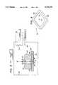
- FIG. 9a partial cross sectional view is shown of the outer jig 30, the inner jig 40, the support surface 50, and the case/band assembly 8.
- the lower surface 36 of the outer jig 30is held by gravity against the upper side 51 of the support surface 50 with the upper jig's channel 38 having a central longitudinal axis within the plane of the paper in FIG. 9, and shown to the left of the cavity 32 of the outer jig 30.
- the case 10is inserted into the inner jig's cavity 42 until it seats against the closed end 44 and sides 46 of the inner jig 40.
- the band 12is inserted into the cavity 42 until it seats against the case 10 and the sides 46 of the cavity 40.
- the band 12protrudes from the cavity when seated against the case 10 and sides 46.
- the interior surface of the cavity 42, as well as the upper side 51 of the support surface 50,is coated with powdered titanium oxide (TO 2 ) to prevent the case 10 and band 12 from bonding to the inner jig 40 and support surface 50.
- powdered titanium oxideTO 2
- the inner jig 40with the band 12 protruding therefrom, is inserted cavity-first into the outer jig 30 through the open end of the outer jig's cavity 32 at the upper surface 34 of the outer jig 30.
- the inner jig 40is inserted into the outer jig's cavity 32 until the band 12 protruding from the inner jig 30 seats against the support surface.
- the inner jig 30does not come into contact with the support surface 50.
- the inner jig 30While the inner jig 30 is sliding into the outer jig's cavity 32, the inner jig's movement is restricted to movement along a single coordinate axis, which is preferably normal to the support surface 34, i.e., the plane defining the upper side 51 of the support surface 50.
- the other open end of the bandi.e., the open end of the band 12 that is not seated against the case 10, is centered over the vent hole 54, and a chamber formed by the space within the outer jig's cavity 32, below the inner jig 40, above the support surface 50 and outside the band 12, is vented by the channel 38 in the outer jig 30.
- the support surface 50, outer jig 30, inner jig 40, case 10 and band 12are placed onto, e.g., a grate (not shown) in a vacuum oven 70, and a compressive force F is applied along the single coordinate axis to the inner jig 40 in a downward direction, as depicted in FIG. 9 by the downward pointing arrow.
- This forcemay be applied by placing weights subject to gravity on top of the inner jig 40.
- the weightscan be secured by wrapping stainless steel bands over the top of the weights and securing them under the support surface 50.
- four or more bands having a width of 1.27 cm and a thickness of 0.025 cmare used.
- the compressive force appliedshould be from between 950 N/m 2 to 1500 N/m 2 .
- the compressive force Fis translated to the case 10 by the inner jig 40. Note also that an equal force is applied by the support surface 50, to the band 12 along the single coordinate axis opposite the direction of the compressive force F.
- the compressive force F and the opposing equal forceisodynamically press the case 10 and band 12 together at the site where the second flat annular surface 20 of the band 12 is seated against the first flat annular surface 18 of the case 10.
- a sealed chamber of the vacuum oven 70is evacuated to at least 10 -5 , preferably 10 -6 , atmospheres using a vacuum pump 72.
- the vacuum oven 70is then heated by energizing a heating coil 74 using a power supply 76.
- the temperature in the vacuum ovenis heated at the rate of approximately 5° C./minute until it reaches a temperature of at least 1000° C., preferably to between 1000° C. and 1100° C. This temperature is maintained for about 2 hours, i.e., 120 minutes, by a thermostat 78 that is coupled to the power supply 76.
- the thermostat 78uses a temperature probe 80 to monitor the temperature within the vacuum oven 70.
- the vacuum oven 70is cooled at a rate of approximately 1° C./minute, which generally takes about 17 hours, e.g., 1000 minutes, at ambient temperature.
- no forced coolingis performed, i.e., no cold gas spray, or other exposure to a cold environment.
- the heating coil 74will generally remain energized, at least partially, in order to assure that the desired slow rate of cooling is achieved, i.e., 1° C./minute.
- titanium atoms from the banddiffuse into the alumina of the case 10. This is caused by an attraction of the titanium atoms to oxygen atoms that are loosely held by the alumina at the above-mentioned temperatures.
- the titanium atomsshare the oxygen atoms with the alumina.
- a hermetically sealed bondis formed between the case 10 and band 12, so that the case 10 and band 12 can be safely utilized to house an implantable electronic device.
- the bondingdoes not degrade or crack the metal or ceramic, and they each maintain their hermeticity.
- a header plate(not shown) is used to seal the other end of the band after electronic circuits, and, e.g., inductive pickup coils, are inserted into the case/band assembly 8.
- the header plateis bonded to the band by, e.g., welding, as is described in U.S. Pat. No. 4,991,582, previously incorporated herein by reference. Note that because the electronic circuits are not inserted into the case/band assembly 8 until after the cooling, and because the header plate can be sealed to the other open end of the band 12 without the need for heating the entire case/band assembly 8 to high temperatures, the electronics are much less prone to suffer heat damage than with many heretofore utilized techniques for bonding the ceramic case 10 to the metal band 12.
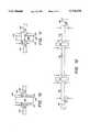
- FIG. 10a cross-sectional view is shown of a case 100 and an electrical feedthrough 102 of a first variation having been bonded together in accordance with another embodiment of the invention.
- the electrical feedthrough 102is generally cylindrical in shape with first and second end portions 104, 106, and a center portion 108.
- the center portion 108(or flange 108) has a radius greater than the radius at the first and second end portions 104, 106 so as to form a flange in the center of the electrical feedthrough 102.
- the case 100which is shown sectionally, has a circular hole 110 that passes therethrough.
- the circular hole 110has a radius larger than the radius of the first and second end portions 104, 106 of the electrical feedthrough 102, but smaller than the radius of the center portion 108 (or flange 108) of the electrical feedthrough 102.
- the first end portion 102 of the electrical feedthrough 102is passed through the hole 110 in the case 100 until a first side 112 of the center portion 108, which is adjacent to the first end portion 104, rests against the periphery 114 of the hole 110 in the case 100.
- a body-safe metale.g., an alloy of Titanium-45 Niobium (i.e., 55% Ti and 45% Nb), which is the same material used to make the band 12 (FIG.
- the first side 112 center portion 108 of the electrical feedthrough 102is compressed against the periphery 114 of the hole 110 in the case 100 at which the first side 112 of the center portion 108 contacts the periphery 114 of the hole 110.
- Such compressionis achieved by applying a compressive force as indicated by arrows in FIG. 10.
- the case 100which is preferably made from a body-safe ceramic, e.g., alumina (AlO 2 ) or zirconium oxide (ZO 2 ), and the electrical feedthrough 102 are placed into a vacuum oven, such as the vacuum oven 70 (FIG. 9) described above, and are heated while the compressive force is applied to compress the periphery 114 of the hole 110 and the first side 112 of the center portion 108 together.
- the compressive forceis preferably a force of from between 100-200 pounds per square inch, and the heating is to a temperature of from between 900°-1100° C. Both the compressive force and the temperature are maintained for approximately two hours, as described above. After the two hours, the vacuum oven 70 (FIG.
- the heating coil 74 (FIG. 9) of the vacuum oven 70 (FIG. 9)will generally remain energized, at least partially, during the cooling of the vacuum oven 70 (FIG. 9) in order to assure that the desired slow rate of cooling is achieved, i.e., 1° C. per minute.
- a number of different materialscan be used in the electrical feedthrough 102 and the case 100 of the present embodiment.
- metalssuch as Titanium, Niobium, Zirconium, and Tantalum can be used in the electrical feedthrough with favorable results.
- Both Alumina and/or Zirconiamay be used to form the case 100.
- Trace elementssuch as Yitria and Magnesia may also be included in the case 100.
- the particular alloy or metal selected for the electrical feedthrough 102, and the ceramic selected for the case 100should have thermal coefficients of expansion (TCE's) that are the same, or very close to one another.
- weights or clampsmay be used to compress the first surface 112 of the center portion 108 of the electrical feedthrough 102 against the periphery 114 of the hole 110 in the case 100.
- Such weights and clampscan be applied using a jig, similar to the jig 40 (FIG. 6) described above, which will be designed specifically for the application of the compressive force to the particular materials to which the teachings of the present embodiment are applied, e.g., the case 100 and electrical feedthrough 102.
- Boron Nitride powdercan be utilized as a masking material, coating the weights, clamps, jig and supporting structures.
- the electrical feedthrough 120which may be made from materials such as those from which the electrical feedthrough 102 of FIG. 10 can be made, includes first and second cylindrical end portions 124, 126 and a frustioconical center portion 128 (or flange 128) having a radius at one end 130 of the center portion equal to the radius of the first end portion 124, and a radius at another end 132 (i.e., outer edge) of the center portion 128 that is about twice as large as the radius of the second end portion 126.
- the first and second end portions 124, 128preferably have radiuses that are approximately equal to one another.
- the case 100which is shown sectionally, may be made from the ceramic materials described above in reference to FIG. 10, and includes a hole 134 therein.
- the hole 134 in the case 100has a frustioconical inner surface having a slope equal to the slope of the frustioconical center portion 128 of the electrical feedthrough 120.
- the first end portion 124 of the electrical feedthrough 120is placed through the hole 134 in a direction moving from that portion of the frustioconical inner surface of the hole 134 with a larger radius toward that portion of the frustioconical inner surface of the hole 134 with a smaller radius, such that the frustioconical center portion 128 of the electrical feedthrough 120 comes to rest (or seat) against the frustioconical inner surface of the hole 134 in the case 100.
- the frustioconical outer surface of the center portion 128 of the electrical feedthrough 120is then compressed against the frustioconical inner surface of the hole 134 in the case 100. Such compression is accomplished by applying a compressive force (represented by arrows) against the other edge 132 of the center portion 128 and against the opposing periphery 136 of the hole 134.
- the case 100 and electrical feedthrough 120are placed into the vacuum oven 70 (FIG. 9) and are heated.
- the amount of compressive force, the temperature to which the electrical feedthrough 120 and the case 100 are heated, the period of time of such heating, and the cooling period and rateare as described above in reference to FIG. 10.
- FIG. 12a cross sectional view is shown of a ceramic plug 142, a plurality of electrical feedthroughs 144, and an outer mounting ring 140, wherein the electrical feedthroughs 144 and the mounting ring 140 have been bonded to the ceramic plug 142 in accordance with a further embodiment of the invention.
- the electrical feedthroughs 144are of the variation depicted in FIG. 10 (but could be of the variation depicted in FIG. 11), and are bonded to the ceramic plug 142 as described in reference to FIG. 10 (except that the ceramic plug 142 replaces the case 100).
- the ceramic plug 142is further bonded to the outer mounting ring 140, in a manner similar to that in which the electrical feedthroughs 144 are bonded to the ceramic plug 142.
- Such bondingis achieved using the amount compressive force, temperature, and heating and cooling periods described above in reference to FIG. 10.
- the compressive forceis applied at the locations indicated in FIG. 12 with arrows.
- the outer mounting ring 140includes a recessed portion 146 designed to accommodate the ceramic plug 142, and to which the ceramic plug 142 is bonded.
- the outer mounting ring 140preferably forms an integral part of the header plate, mentioned above, which is used to close the metal band, also mentioned above.
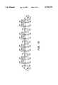
- FIG. 13a cross sectional view is shown of a plurality of ceramic plugs 142, a plurality of electrical feedthroughs 144, a plurality of outer mounting rings 140, a header plate 148, the metal band 12, and a plurality of connecting wires 150, 152.
- the electrical feedthroughs 144 and the mounting ring 140have been bonded to the ceramic plug 142 in accordance with the embodiment of the invention of FIG. 12.
- the electrical feedthroughs 144are of the variation depicted in FIG. 10 (but could be of the variation depicted in FIG. 11), and are bonded to the ceramic plugs 142, as described in reference to FIG. 12.
- the ceramic plugs 142are further bonded to the outer mounting ring 140, in a manner similar to that in which the electrical feedthroughs are bonded to the ceramic plugs 142. Such bonding is achieved using the amount compressive force, temperature, and heating and cooling periods described above in reference to FIG. 10.
- the outer mounting rings 140preferably form an integral part of the header plate 149 (see, e.g., U.S. Pat. No. 4,991,582, previously incorporated herein by reference), which is used to close the metal band 12, as mentioned above.
- Such closing of the metal band 12is achieved by welding the header plate into the flanged edge 24 (FIG. 2) of the metal band 12 (FIG. 2) using conventional welding techniques.
- the connecting wires 150, 152are welded to respective first and second cylindrical end portions 104, 106 (FIG. 10) of the electrical feedthroughs 144 (102 in FIG. 10) using conventional welding techniques.
- the connecting wiresare then used to electrically connect electronic circuitry housed within the ceramic case 10 (FIG. 1), such as an implantable cochlear stimulation circuit, to electronic circuitry external to the case 10 (FIG. 1), such as cochlear stimulation electrodes, while maintaining a hermetic seal between the contents of the case 10 and structures, such as physiological structures, outside the case.
- a hermetically sealed electrical feedthroughis provided for electrically connecting a first set of electronic components with a second set of electronic components, while maintain a hermetic barrier between such components.
Landscapes
- Health & Medical Sciences (AREA)
- Engineering & Computer Science (AREA)
- Chemical & Material Sciences (AREA)
- Life Sciences & Earth Sciences (AREA)
- Veterinary Medicine (AREA)
- Mechanical Engineering (AREA)
- Public Health (AREA)
- General Health & Medical Sciences (AREA)
- Animal Behavior & Ethology (AREA)
- Heart & Thoracic Surgery (AREA)
- Biomedical Technology (AREA)
- Vascular Medicine (AREA)
- Chemical Kinetics & Catalysis (AREA)
- Surgery (AREA)
- Metallurgy (AREA)
- Materials Engineering (AREA)
- Ceramic Engineering (AREA)
- Inorganic Chemistry (AREA)
- Radiology & Medical Imaging (AREA)
- Organic Chemistry (AREA)
- Nuclear Medicine, Radiotherapy & Molecular Imaging (AREA)
- Epidemiology (AREA)
- Cardiology (AREA)
- Oral & Maxillofacial Surgery (AREA)
- Transplantation (AREA)
- Ceramic Products (AREA)
Abstract
Description
Claims (19)
Priority Applications (1)
| Application Number | Priority Date | Filing Date | Title |
|---|---|---|---|
| US08/625,513US5738270A (en) | 1994-10-07 | 1996-03-25 | Brazeless ceramic-to-metal bonding for use in implantable devices |
Applications Claiming Priority (2)
| Application Number | Priority Date | Filing Date | Title |
|---|---|---|---|
| US08/319,580US5513793A (en) | 1994-10-07 | 1994-10-07 | Brazeless ceramic-to-metal bond for use in implantable devices |
| US08/625,513US5738270A (en) | 1994-10-07 | 1996-03-25 | Brazeless ceramic-to-metal bonding for use in implantable devices |
Related Parent Applications (1)
| Application Number | Title | Priority Date | Filing Date |
|---|---|---|---|
| US08/319,580Continuation-In-PartUS5513793A (en) | 1994-10-07 | 1994-10-07 | Brazeless ceramic-to-metal bond for use in implantable devices |
Publications (1)
| Publication Number | Publication Date |
|---|---|
| US5738270Atrue US5738270A (en) | 1998-04-14 |
Family
ID=46251870
Family Applications (1)
| Application Number | Title | Priority Date | Filing Date |
|---|---|---|---|
| US08/625,513Expired - LifetimeUS5738270A (en) | 1994-10-07 | 1996-03-25 | Brazeless ceramic-to-metal bonding for use in implantable devices |
Country Status (1)
| Country | Link |
|---|---|
| US (1) | US5738270A (en) |
Cited By (49)
| Publication number | Priority date | Publication date | Assignee | Title |
|---|---|---|---|---|
| WO2000056677A1 (en)* | 1999-03-24 | 2000-09-28 | Alfred E. Mann Foundation | Method and apparatus of a strong metal-ceramic braze bond |
| US6537201B1 (en) | 2001-09-28 | 2003-03-25 | Otologics Llc | Implantable hearing aid with improved sealing |
| US20040058186A1 (en)* | 2002-06-28 | 2004-03-25 | Jay Daulton | Self-centering braze assembly |
| US20050033370A1 (en)* | 2003-06-06 | 2005-02-10 | Jeff Jelen | Implantable medical device including a hermetic connector block extension |
| US20050075683A1 (en)* | 2003-10-03 | 2005-04-07 | Miesel Keith Alan | System, apparatus and method for interacting with a targeted tissue of a patient |
| US20050137670A1 (en)* | 2003-12-19 | 2005-06-23 | Christopherson Mark A. | Electrical lead body including an in-line hermetic electronic package and implantable medical device using the same |
| US20050148980A1 (en)* | 2003-12-30 | 2005-07-07 | Kimberly-Clark Worldwide, Inc. | Absorbent garment having outer shell and discreet absorbent assembly adapted for positioning therein |
| US20060105589A1 (en)* | 2004-11-12 | 2006-05-18 | Agc Automotive Americas R&D, Inc | Window pane and a method of bonding a connector to the window pane |
| US20060102610A1 (en)* | 2004-11-12 | 2006-05-18 | Agc Automotive Americas R&D, Inc. | Electrical connector for a window pane of a vehicle |
| US20060257636A1 (en)* | 2002-12-19 | 2006-11-16 | Mike Muhl | Thermally stable and liquid-tight joint between a first ceramic, metal, or plastic component and a second ceramic, metal or plastic component, and the use of one such joint |
| US20060283624A1 (en)* | 2001-03-30 | 2006-12-21 | Jerry Ok | Method and apparatus for providing hermetic electrical feedthrough |
| EP1897588A1 (en)* | 2006-09-07 | 2008-03-12 | BIOTRONIK CRM Patent AG | Feedthrough connection |
| US7498516B1 (en) | 2006-06-14 | 2009-03-03 | Boston Scientific Neuromodulation Corporation | Feedthru assembly |
| US7771838B1 (en) | 2004-10-12 | 2010-08-10 | Boston Scientific Neuromodulation Corporation | Hermetically bonding ceramic and titanium with a Ti-Pd braze interface |
| US20110034965A1 (en)* | 2009-08-04 | 2011-02-10 | W. C. Heraeus Gmbh | Cermet-containing bushing for an implantable medical device |
| US20110034966A1 (en)* | 2009-08-04 | 2011-02-10 | W. C. Heraeus Gmbh | Electrical bushing for an implantable medical device |
| US20110186349A1 (en)* | 2010-02-02 | 2011-08-04 | W. C. Heraeus Gmbh | Electrical bushing with gradient cermet |
| US20110190885A1 (en)* | 2010-02-02 | 2011-08-04 | W. C. Heraeus Gmbh | Method for sintering electrical bushings |
| US20120193118A1 (en)* | 2011-01-31 | 2012-08-02 | Heraeus Precious Materials Gmbh & Co. Kg | Directly applicable electrical bushing |
| WO2012082901A3 (en)* | 2010-12-15 | 2012-09-20 | Advanced Bionics Ag | Electrical feedthrough with a structured interface |
| US8329314B1 (en) | 2004-10-12 | 2012-12-11 | Boston Scientific Neuromodulation Corporation | Hermetically bonding ceramic and titanium with a palladium braze |
| US8386047B2 (en) | 2010-07-15 | 2013-02-26 | Advanced Bionics | Implantable hermetic feedthrough |
| US8552311B2 (en) | 2010-07-15 | 2013-10-08 | Advanced Bionics | Electrical feedthrough assembly |
| WO2014049089A1 (en)* | 2012-09-28 | 2014-04-03 | Csem Centre Suisse D'electronique Et De Microtechnique Sa - Recherche Et Developpement | Implantable devices |
| US9040819B2 (en) | 2011-01-31 | 2015-05-26 | Heraeus Precious Metals Gmbh & Co. Kg | Implantable device having an integrated ceramic bushing |
| US9088093B2 (en) | 2011-01-31 | 2015-07-21 | Heraeus Precious Metals Gmbh & Co. Kg | Head part for an implantable medical device |
| US9126053B2 (en) | 2011-01-31 | 2015-09-08 | Heraeus Precious Metals Gmbh & Co. Kg | Electrical bushing with cermet-containing connecting element for an active implantable medical device |
| CN105287047A (en)* | 2015-11-03 | 2016-02-03 | 深圳硅基仿生科技有限公司 | Sealing structure of implantable device and manufacturing method thereof |
| US9272371B2 (en) | 2013-05-30 | 2016-03-01 | Agc Automotive Americas R&D, Inc. | Solder joint for an electrical conductor and a window pane including same |
| US9306318B2 (en) | 2011-01-31 | 2016-04-05 | Heraeus Deutschland GmbH & Co. KG | Ceramic bushing with filter |
| US9403023B2 (en) | 2013-08-07 | 2016-08-02 | Heraeus Deutschland GmbH & Co. KG | Method of forming feedthrough with integrated brazeless ferrule |
| US9431801B2 (en) | 2013-05-24 | 2016-08-30 | Heraeus Deutschland GmbH & Co. KG | Method of coupling a feedthrough assembly for an implantable medical device |
| US9478959B2 (en) | 2013-03-14 | 2016-10-25 | Heraeus Deutschland GmbH & Co. KG | Laser welding a feedthrough |
| CN106145963A (en)* | 2015-12-31 | 2016-11-23 | 深圳硅基仿生科技有限公司 | There is the artificial retina sealing structure |
| US9504841B2 (en) | 2013-12-12 | 2016-11-29 | Heraeus Deutschland GmbH & Co. KG | Direct integration of feedthrough to implantable medical device housing with ultrasonic welding |
| US9504840B2 (en) | 2011-01-31 | 2016-11-29 | Heraeus Deutschland GmbH & Co. KG | Method of forming a cermet-containing bushing for an implantable medical device having a connecting layer |
| US9509272B2 (en) | 2011-01-31 | 2016-11-29 | Heraeus Deutschland GmbH & Co. KG | Ceramic bushing with filter |
| US9552899B2 (en) | 2011-01-31 | 2017-01-24 | Heraeus Deutschland GmbH & Co. KG | Ceramic bushing for an implantable medical device |
| US9610452B2 (en) | 2013-12-12 | 2017-04-04 | Heraeus Deutschland GmbH & Co. KG | Direct integration of feedthrough to implantable medical device housing by sintering |
| US9610451B2 (en) | 2013-12-12 | 2017-04-04 | Heraeus Deutschland GmbH & Co. KG | Direct integration of feedthrough to implantable medical device housing using a gold alloy |
| US20180050210A1 (en)* | 2016-08-17 | 2018-02-22 | Heraeus Deutschland GmbH & Co. KG | Cermet feedthrough in ceramic multilayer body |
| US10092766B2 (en) | 2011-11-23 | 2018-10-09 | Heraeus Deutschland GmbH & Co. KG | Capacitor and method to manufacture the capacitor |
| US10213611B2 (en)* | 2015-06-30 | 2019-02-26 | Osong Medical Innovation Foundation | Method of manufacturing feedthrough |
| US10263362B2 (en) | 2017-03-29 | 2019-04-16 | Agc Automotive Americas R&D, Inc. | Fluidically sealed enclosure for window electrical connections |
| US10849192B2 (en) | 2017-04-26 | 2020-11-24 | Agc Automotive Americas R&D, Inc. | Enclosure assembly for window electrical connections |
| US10888009B2 (en) | 2018-10-26 | 2021-01-05 | Medtronic, Inc. | Method of forming a sealed package |
| US11109985B2 (en) | 2016-02-23 | 2021-09-07 | Ottobock Se & Co. Kgaa | Method for making a mold of an amputation stump, and molding aid for such a method |
| US11701519B2 (en) | 2020-02-21 | 2023-07-18 | Heraeus Medical Components Llc | Ferrule with strain relief spacer for implantable medical device |
| US11894163B2 (en) | 2020-02-21 | 2024-02-06 | Heraeus Medical Components Llc | Ferrule for non-planar medical device housing |
Citations (17)
| Publication number | Priority date | Publication date | Assignee | Title |
|---|---|---|---|---|
| US3784726A (en)* | 1971-05-20 | 1974-01-08 | Hewlett Packard Co | Microcircuit package assembly |
| US3786559A (en)* | 1972-05-22 | 1974-01-22 | Hewlett Packard Co | Cold diffusion welds in a microcircuit package assembly |
| US4041955A (en)* | 1976-01-29 | 1977-08-16 | Pacesetter Systems Inc. | Implantable living tissue stimulator with an improved hermetic metal container |
| US4159075A (en)* | 1977-12-02 | 1979-06-26 | The Singer Company | Hermetic bonded seal |
| US4525766A (en)* | 1984-01-25 | 1985-06-25 | Transensory Devices, Inc. | Method and apparatus for forming hermetically sealed electrical feedthrough conductors |
| US4618802A (en)* | 1984-10-29 | 1986-10-21 | Gte Products Corporation | Hermetically sealed enclosure for thin film devices |
| US4627958A (en)* | 1983-12-27 | 1986-12-09 | Gray Tool Company | Densification of metal powder to produce cladding of valve interiors by isodynamic compression |
| US4693409A (en)* | 1982-06-29 | 1987-09-15 | Tokyo Shibarua Denki Kabushiki Kaisha | Method for directly bonding ceramic and metal members and laminated body of the same |
| US4725480A (en)* | 1985-09-24 | 1988-02-16 | John Fluke Mfg. Co., Inc. | Hermetically sealed electronic component |
| US4729504A (en)* | 1985-06-01 | 1988-03-08 | Mizuo Edamura | Method of bonding ceramics and metal, or bonding similar ceramics among themselves; or bonding dissimilar ceramics |
| US4861641A (en)* | 1987-05-22 | 1989-08-29 | Ceramics Process Systems Corporation | Substrates with dense metal vias |
| US4882298A (en)* | 1987-07-30 | 1989-11-21 | Messerschmitt-Boelkow-Blohm Gmbh | Method for encapsulating microelectronic semiconductor and thin film devices |
| US4906311A (en)* | 1985-09-24 | 1990-03-06 | John Fluke Co., Inc. | Method of making a hermetically sealed electronic component |
| US4991582A (en)* | 1989-09-22 | 1991-02-12 | Alfred E. Mann Foundation For Scientific Research | Hermetically sealed ceramic and metal package for electronic devices implantable in living bodies |
| USRE33859E (en)* | 1985-09-24 | 1992-03-24 | John Fluke Mfg. Co., Inc. | Hermetically sealed electronic component |
| US5181647A (en)* | 1990-12-14 | 1993-01-26 | Mcdonnell Douglas Corporation | Method and tooling for fabricating monolithic metal or metal matrix composite structures |
| WO1994008539A1 (en)* | 1992-10-20 | 1994-04-28 | Cochlear Pty. Ltd. | Package and method of construction |
- 1996
- 1996-03-25USUS08/625,513patent/US5738270A/ennot_activeExpired - Lifetime
Patent Citations (17)
| Publication number | Priority date | Publication date | Assignee | Title |
|---|---|---|---|---|
| US3784726A (en)* | 1971-05-20 | 1974-01-08 | Hewlett Packard Co | Microcircuit package assembly |
| US3786559A (en)* | 1972-05-22 | 1974-01-22 | Hewlett Packard Co | Cold diffusion welds in a microcircuit package assembly |
| US4041955A (en)* | 1976-01-29 | 1977-08-16 | Pacesetter Systems Inc. | Implantable living tissue stimulator with an improved hermetic metal container |
| US4159075A (en)* | 1977-12-02 | 1979-06-26 | The Singer Company | Hermetic bonded seal |
| US4693409A (en)* | 1982-06-29 | 1987-09-15 | Tokyo Shibarua Denki Kabushiki Kaisha | Method for directly bonding ceramic and metal members and laminated body of the same |
| US4627958A (en)* | 1983-12-27 | 1986-12-09 | Gray Tool Company | Densification of metal powder to produce cladding of valve interiors by isodynamic compression |
| US4525766A (en)* | 1984-01-25 | 1985-06-25 | Transensory Devices, Inc. | Method and apparatus for forming hermetically sealed electrical feedthrough conductors |
| US4618802A (en)* | 1984-10-29 | 1986-10-21 | Gte Products Corporation | Hermetically sealed enclosure for thin film devices |
| US4729504A (en)* | 1985-06-01 | 1988-03-08 | Mizuo Edamura | Method of bonding ceramics and metal, or bonding similar ceramics among themselves; or bonding dissimilar ceramics |
| US4725480A (en)* | 1985-09-24 | 1988-02-16 | John Fluke Mfg. Co., Inc. | Hermetically sealed electronic component |
| US4906311A (en)* | 1985-09-24 | 1990-03-06 | John Fluke Co., Inc. | Method of making a hermetically sealed electronic component |
| USRE33859E (en)* | 1985-09-24 | 1992-03-24 | John Fluke Mfg. Co., Inc. | Hermetically sealed electronic component |
| US4861641A (en)* | 1987-05-22 | 1989-08-29 | Ceramics Process Systems Corporation | Substrates with dense metal vias |
| US4882298A (en)* | 1987-07-30 | 1989-11-21 | Messerschmitt-Boelkow-Blohm Gmbh | Method for encapsulating microelectronic semiconductor and thin film devices |
| US4991582A (en)* | 1989-09-22 | 1991-02-12 | Alfred E. Mann Foundation For Scientific Research | Hermetically sealed ceramic and metal package for electronic devices implantable in living bodies |
| US5181647A (en)* | 1990-12-14 | 1993-01-26 | Mcdonnell Douglas Corporation | Method and tooling for fabricating monolithic metal or metal matrix composite structures |
| WO1994008539A1 (en)* | 1992-10-20 | 1994-04-28 | Cochlear Pty. Ltd. | Package and method of construction |
Cited By (81)
| Publication number | Priority date | Publication date | Assignee | Title |
|---|---|---|---|---|
| WO2000056677A1 (en)* | 1999-03-24 | 2000-09-28 | Alfred E. Mann Foundation | Method and apparatus of a strong metal-ceramic braze bond |
| US20060283624A1 (en)* | 2001-03-30 | 2006-12-21 | Jerry Ok | Method and apparatus for providing hermetic electrical feedthrough |
| US8163397B2 (en) | 2001-03-30 | 2012-04-24 | Second Sight Medical Products, Inc. | Method and apparatus for providing hermetic electrical feedthrough |
| US7989080B2 (en) | 2001-03-30 | 2011-08-02 | Second Sight Medical Products, Inc. | Method and apparatus for providing hermetic electrical feedthrough |
| US7480988B2 (en) | 2001-03-30 | 2009-01-27 | Second Sight Medical Products, Inc. | Method and apparatus for providing hermetic electrical feedthrough |
| US6537201B1 (en) | 2001-09-28 | 2003-03-25 | Otologics Llc | Implantable hearing aid with improved sealing |
| US7103408B2 (en) | 2002-06-28 | 2006-09-05 | Advanced Bionics Corporation | Electrode assembly for a microstimulator |
| US7132173B2 (en) | 2002-06-28 | 2006-11-07 | Advanced Bionics Corporation | Self-centering braze assembly |
| US20040058186A1 (en)* | 2002-06-28 | 2004-03-25 | Jay Daulton | Self-centering braze assembly |
| US20040088032A1 (en)* | 2002-06-28 | 2004-05-06 | Haller Matthew I. | Electrode assembly for a microstimulator |
| US7764505B2 (en) | 2002-12-19 | 2010-07-27 | Testo Ag | Thermally stable and liquid-tight joint between a first ceramic, metal, or plastic component and a second ceramic, metal or plastic component, and the use of one such joint |
| US20060257636A1 (en)* | 2002-12-19 | 2006-11-16 | Mike Muhl | Thermally stable and liquid-tight joint between a first ceramic, metal, or plastic component and a second ceramic, metal or plastic component, and the use of one such joint |
| US20050033370A1 (en)* | 2003-06-06 | 2005-02-10 | Jeff Jelen | Implantable medical device including a hermetic connector block extension |
| US7254443B2 (en) | 2003-06-06 | 2007-08-07 | Medtronic, Inc. | Implantable medical device including a hermetic connector block extension |
| US8489196B2 (en) | 2003-10-03 | 2013-07-16 | Medtronic, Inc. | System, apparatus and method for interacting with a targeted tissue of a patient |
| US20050075683A1 (en)* | 2003-10-03 | 2005-04-07 | Miesel Keith Alan | System, apparatus and method for interacting with a targeted tissue of a patient |
| US20050137670A1 (en)* | 2003-12-19 | 2005-06-23 | Christopherson Mark A. | Electrical lead body including an in-line hermetic electronic package and implantable medical device using the same |
| US7236834B2 (en) | 2003-12-19 | 2007-06-26 | Medtronic, Inc. | Electrical lead body including an in-line hermetic electronic package and implantable medical device using the same |
| US20050148980A1 (en)* | 2003-12-30 | 2005-07-07 | Kimberly-Clark Worldwide, Inc. | Absorbent garment having outer shell and discreet absorbent assembly adapted for positioning therein |
| US8329314B1 (en) | 2004-10-12 | 2012-12-11 | Boston Scientific Neuromodulation Corporation | Hermetically bonding ceramic and titanium with a palladium braze |
| US7771838B1 (en) | 2004-10-12 | 2010-08-10 | Boston Scientific Neuromodulation Corporation | Hermetically bonding ceramic and titanium with a Ti-Pd braze interface |
| US7223939B2 (en) | 2004-11-12 | 2007-05-29 | Agc Automotive Americas, R & D, Inc. | Electrical connector for a window pane of a vehicle |
| US20060105589A1 (en)* | 2004-11-12 | 2006-05-18 | Agc Automotive Americas R&D, Inc | Window pane and a method of bonding a connector to the window pane |
| US20060102610A1 (en)* | 2004-11-12 | 2006-05-18 | Agc Automotive Americas R&D, Inc. | Electrical connector for a window pane of a vehicle |
| US7134201B2 (en) | 2004-11-12 | 2006-11-14 | Agc Automotive Americas R&D, Inc. | Window pane and a method of bonding a connector to the window pane |
| US20090139765A1 (en)* | 2006-06-14 | 2009-06-04 | Boston Scientific Neuromodulation Corporation | Feedthru assembly |
| US7498516B1 (en) | 2006-06-14 | 2009-03-03 | Boston Scientific Neuromodulation Corporation | Feedthru assembly |
| US7939762B2 (en) | 2006-06-14 | 2011-05-10 | Boston Scientific Neuromodulation Corporation | Feedthru assembly |
| EP1897588A1 (en)* | 2006-09-07 | 2008-03-12 | BIOTRONIK CRM Patent AG | Feedthrough connection |
| US20080060834A1 (en)* | 2006-09-07 | 2008-03-13 | Stefan Eck | Electrical feedthrough |
| US20110034966A1 (en)* | 2009-08-04 | 2011-02-10 | W. C. Heraeus Gmbh | Electrical bushing for an implantable medical device |
| US10290400B2 (en) | 2009-08-04 | 2019-05-14 | Heraeus Deutschland GmbH & Co. KG | Method of producing a cermet-containing bushing for an implantable medical device |
| US9480168B2 (en) | 2009-08-04 | 2016-10-25 | Heraeus Deutschland GmbH & Co. KG | Method of producing a cermet-containing bushing for an implantable medical device |
| US20110034965A1 (en)* | 2009-08-04 | 2011-02-10 | W. C. Heraeus Gmbh | Cermet-containing bushing for an implantable medical device |
| US8929987B2 (en) | 2009-08-04 | 2015-01-06 | Heraeus Precious Metals Gmbh & Co. Kg | Electrical bushing for an implantable medical device |
| US8755887B2 (en) | 2009-08-04 | 2014-06-17 | Heraeus Precious Metals Gmbh & Co. Kg | Cermet-containing bushing for an implantable medical device |
| US20110190885A1 (en)* | 2010-02-02 | 2011-08-04 | W. C. Heraeus Gmbh | Method for sintering electrical bushings |
| US20110186349A1 (en)* | 2010-02-02 | 2011-08-04 | W. C. Heraeus Gmbh | Electrical bushing with gradient cermet |
| US9407076B2 (en) | 2010-02-02 | 2016-08-02 | Heraeus Precious Metals Gmbh & Co. Kg | Electrical bushing with gradient cermet |
| US8494635B2 (en) | 2010-02-02 | 2013-07-23 | W. C. Heraeus Gmbh | Method for sintering electrical bushings |
| US8528201B2 (en) | 2010-02-02 | 2013-09-10 | W. C. Heraeus Gmbh | Method of producing an electrical bushing with gradient cermet |
| US8886320B2 (en) | 2010-02-02 | 2014-11-11 | Heraeus Precious Metals Gmbh & Co. Kg | Sintered electrical bushings |
| US8552311B2 (en) | 2010-07-15 | 2013-10-08 | Advanced Bionics | Electrical feedthrough assembly |
| US8386047B2 (en) | 2010-07-15 | 2013-02-26 | Advanced Bionics | Implantable hermetic feedthrough |
| WO2012082901A3 (en)* | 2010-12-15 | 2012-09-20 | Advanced Bionics Ag | Electrical feedthrough with a structured interface |
| US20120193118A1 (en)* | 2011-01-31 | 2012-08-02 | Heraeus Precious Materials Gmbh & Co. Kg | Directly applicable electrical bushing |
| US9040819B2 (en) | 2011-01-31 | 2015-05-26 | Heraeus Precious Metals Gmbh & Co. Kg | Implantable device having an integrated ceramic bushing |
| US9088093B2 (en) | 2011-01-31 | 2015-07-21 | Heraeus Precious Metals Gmbh & Co. Kg | Head part for an implantable medical device |
| US9126053B2 (en) | 2011-01-31 | 2015-09-08 | Heraeus Precious Metals Gmbh & Co. Kg | Electrical bushing with cermet-containing connecting element for an active implantable medical device |
| US9306318B2 (en) | 2011-01-31 | 2016-04-05 | Heraeus Deutschland GmbH & Co. KG | Ceramic bushing with filter |
| US9552899B2 (en) | 2011-01-31 | 2017-01-24 | Heraeus Deutschland GmbH & Co. KG | Ceramic bushing for an implantable medical device |
| US9509272B2 (en) | 2011-01-31 | 2016-11-29 | Heraeus Deutschland GmbH & Co. KG | Ceramic bushing with filter |
| US9504840B2 (en) | 2011-01-31 | 2016-11-29 | Heraeus Deutschland GmbH & Co. KG | Method of forming a cermet-containing bushing for an implantable medical device having a connecting layer |
| US10092766B2 (en) | 2011-11-23 | 2018-10-09 | Heraeus Deutschland GmbH & Co. KG | Capacitor and method to manufacture the capacitor |
| WO2014049089A1 (en)* | 2012-09-28 | 2014-04-03 | Csem Centre Suisse D'electronique Et De Microtechnique Sa - Recherche Et Developpement | Implantable devices |
| US9478959B2 (en) | 2013-03-14 | 2016-10-25 | Heraeus Deutschland GmbH & Co. KG | Laser welding a feedthrough |
| US10418798B2 (en) | 2013-03-14 | 2019-09-17 | Heraeus Deutschland GmbH & Co. KG | Welded feedthrough |
| US10770879B2 (en) | 2013-03-14 | 2020-09-08 | Heraeus Deutschland GmbH & Co. KG | Welded feedthrough |
| US9653893B2 (en) | 2013-05-24 | 2017-05-16 | Heraeus Deutschland GmbH & Co. KG | Ceramic feedthrough brazed to an implantable medical device housing |
| US9431801B2 (en) | 2013-05-24 | 2016-08-30 | Heraeus Deutschland GmbH & Co. KG | Method of coupling a feedthrough assembly for an implantable medical device |
| US9272371B2 (en) | 2013-05-30 | 2016-03-01 | Agc Automotive Americas R&D, Inc. | Solder joint for an electrical conductor and a window pane including same |
| US9403023B2 (en) | 2013-08-07 | 2016-08-02 | Heraeus Deutschland GmbH & Co. KG | Method of forming feedthrough with integrated brazeless ferrule |
| US9814891B2 (en) | 2013-08-07 | 2017-11-14 | Heraeus Duetschland Gmbh & Co. Kg | Feedthrough with integrated brazeless ferrule |
| US9610452B2 (en) | 2013-12-12 | 2017-04-04 | Heraeus Deutschland GmbH & Co. KG | Direct integration of feedthrough to implantable medical device housing by sintering |
| US9849296B2 (en) | 2013-12-12 | 2017-12-26 | Heraeus Deutschland GmbH & Co. KG | Directly integrated feedthrough to implantable medical device housing |
| US9855008B2 (en) | 2013-12-12 | 2018-01-02 | Heraeus Deutschland GmbH & Co. LG | Direct integration of feedthrough to implantable medical device housing with ultrasonic welding |
| US9610451B2 (en) | 2013-12-12 | 2017-04-04 | Heraeus Deutschland GmbH & Co. KG | Direct integration of feedthrough to implantable medical device housing using a gold alloy |
| US9504841B2 (en) | 2013-12-12 | 2016-11-29 | Heraeus Deutschland GmbH & Co. KG | Direct integration of feedthrough to implantable medical device housing with ultrasonic welding |
| US10213611B2 (en)* | 2015-06-30 | 2019-02-26 | Osong Medical Innovation Foundation | Method of manufacturing feedthrough |
| CN106361464A (en)* | 2015-11-03 | 2017-02-01 | 深圳硅基仿生科技有限公司 | Seal structure of implanted device |
| CN105287047A (en)* | 2015-11-03 | 2016-02-03 | 深圳硅基仿生科技有限公司 | Sealing structure of implantable device and manufacturing method thereof |
| CN106145963B (en)* | 2015-12-31 | 2018-10-30 | 深圳硅基仿生科技有限公司 | Artificial retina with sealing structure |
| CN106145963A (en)* | 2015-12-31 | 2016-11-23 | 深圳硅基仿生科技有限公司 | There is the artificial retina sealing structure |
| US11109985B2 (en) | 2016-02-23 | 2021-09-07 | Ottobock Se & Co. Kgaa | Method for making a mold of an amputation stump, and molding aid for such a method |
| US20180050210A1 (en)* | 2016-08-17 | 2018-02-22 | Heraeus Deutschland GmbH & Co. KG | Cermet feedthrough in ceramic multilayer body |
| US9999777B2 (en)* | 2016-08-17 | 2018-06-19 | Heraeus Deutschland GmbH & Co. KG | Cermet feedthrough in ceramic multilayer body |
| US10263362B2 (en) | 2017-03-29 | 2019-04-16 | Agc Automotive Americas R&D, Inc. | Fluidically sealed enclosure for window electrical connections |
| US10849192B2 (en) | 2017-04-26 | 2020-11-24 | Agc Automotive Americas R&D, Inc. | Enclosure assembly for window electrical connections |
| US10888009B2 (en) | 2018-10-26 | 2021-01-05 | Medtronic, Inc. | Method of forming a sealed package |
| US11701519B2 (en) | 2020-02-21 | 2023-07-18 | Heraeus Medical Components Llc | Ferrule with strain relief spacer for implantable medical device |
| US11894163B2 (en) | 2020-02-21 | 2024-02-06 | Heraeus Medical Components Llc | Ferrule for non-planar medical device housing |
Similar Documents
| Publication | Publication Date | Title |
|---|---|---|
| US5738270A (en) | Brazeless ceramic-to-metal bonding for use in implantable devices | |
| US5513793A (en) | Brazeless ceramic-to-metal bond for use in implantable devices | |
| US4991582A (en) | Hermetically sealed ceramic and metal package for electronic devices implantable in living bodies | |
| US5817984A (en) | Implantable medical device wtih multi-pin feedthrough | |
| US5046242A (en) | Method of making feedthrough assemblies having hermetic seals between electrical feedthrough elements and ceramic carriers therefor | |
| US5272283A (en) | Feedthrough assembly for cochlear prosthetic package | |
| US5105811A (en) | Cochlear prosthetic package | |
| WO2000056677A1 (en) | Method and apparatus of a strong metal-ceramic braze bond | |
| US6411854B1 (en) | Implanted ceramic case with enhanced ceramic case strength | |
| US6011993A (en) | Method of making implanted ceramic case with enhanced ceramic case strength | |
| US10770879B2 (en) | Welded feedthrough | |
| US4152540A (en) | Feedthrough connector for implantable cardiac pacer | |
| US4816621A (en) | Ceramic-metal feedthrough lead assembly and method for making same | |
| US6586675B1 (en) | Feedthrough devices | |
| CN103842024A (en) | Method for interconnecting conductors and feedthroughs with pads of sufficient thickness | |
| CN103842026A (en) | Electrical conductors for feedthrough | |
| GB2124495A (en) | Prosthetic package and method of making same | |
| EP1171190B1 (en) | Ceramic case assembly for a microstimulator | |
| US5562716A (en) | Package and method of construction | |
| US6415182B1 (en) | Hermetic ground pin assembly and method of making | |
| JPH0574977A (en) | Crack eliminating method for alumina substrate | |
| US20160271399A1 (en) | Feedthrough of an Implantable Electronic Medical Device and Implantable Electronic Medical Device | |
| AU680634B2 (en) | Package and method of construction | |
| JP2002110265A (en) | Vacuum-tight terminal and electric pot |
Legal Events
| Date | Code | Title | Description |
|---|---|---|---|
| AS | Assignment | Owner name:ADVANCED BIONICS CORPORATION, CALIFORNIA Free format text:ASSIGNMENT OF ASSIGNORS INTEREST;ASSIGNOR:MALMGREN, RICHARD P.;REEL/FRAME:008037/0284 Effective date:19960612 | |
| STCF | Information on status: patent grant | Free format text:PATENTED CASE | |
| FEPP | Fee payment procedure | Free format text:PAYOR NUMBER ASSIGNED (ORIGINAL EVENT CODE: ASPN); ENTITY STATUS OF PATENT OWNER: LARGE ENTITY | |
| FEPP | Fee payment procedure | Free format text:PAYER NUMBER DE-ASSIGNED (ORIGINAL EVENT CODE: RMPN); ENTITY STATUS OF PATENT OWNER: LARGE ENTITY Free format text:PAYOR NUMBER ASSIGNED (ORIGINAL EVENT CODE: ASPN); ENTITY STATUS OF PATENT OWNER: LARGE ENTITY | |
| FEPP | Fee payment procedure | Free format text:PAT HLDR NO LONGER CLAIMS SMALL ENT STAT AS SMALL BUSINESS (ORIGINAL EVENT CODE: LSM2); ENTITY STATUS OF PATENT OWNER: LARGE ENTITY | |
| FPAY | Fee payment | Year of fee payment:4 | |
| FPAY | Fee payment | Year of fee payment:8 | |
| AS | Assignment | Owner name:BOSTON SCIENTIFIC NEUROMODULATION CORPORATION, CAL Free format text:CHANGE OF NAME;ASSIGNOR:ADVANCED BIONICS CORPORATION;REEL/FRAME:020299/0200 Effective date:20071116 | |
| AS | Assignment | Owner name:BOSTON SCIENTIFIC NEUROMODULATION CORPORATION, CAL Free format text:CHANGE OF NAME;ASSIGNOR:ADVANCED BIONICS CORPORATION;REEL/FRAME:020309/0361 Effective date:20071116 | |
| AS | Assignment | Owner name:ADVANCED BIONICS, LLC, CALIFORNIA Free format text:ASSIGNMENT OF ASSIGNORS INTEREST;ASSIGNOR:BOSTON SCIENTIFIC NEUROMODULATION CORPORATION;REEL/FRAME:020340/0713 Effective date:20080107 Owner name:ADVANCED BIONICS, LLC,CALIFORNIA Free format text:ASSIGNMENT OF ASSIGNORS INTEREST;ASSIGNOR:BOSTON SCIENTIFIC NEUROMODULATION CORPORATION;REEL/FRAME:020340/0713 Effective date:20080107 | |
| FPAY | Fee payment | Year of fee payment:12 | |
| AS | Assignment | Owner name:ADVANCED BIONICS AG, SWITZERLAND Free format text:ASSIGNMENT OF ASSIGNORS INTEREST;ASSIGNOR:ADVANCED BIONICS, LLC;REEL/FRAME:051063/0829 Effective date:20111130 |