US5738251A - Trigger sprayer - Google Patents
Trigger sprayerDownload PDFInfo
- Publication number
- US5738251A US5738251AUS08/768,096US76809696AUS5738251AUS 5738251 AUS5738251 AUS 5738251AUS 76809696 AUS76809696 AUS 76809696AUS 5738251 AUS5738251 AUS 5738251A
- Authority
- US
- United States
- Prior art keywords
- housing
- vent
- pump
- lever
- container
- Prior art date
- Legal status (The legal status is an assumption and is not a legal conclusion. Google has not performed a legal analysis and makes no representation as to the accuracy of the status listed.)
- Expired - Lifetime
Links
Images


Classifications
- B—PERFORMING OPERATIONS; TRANSPORTING
- B05—SPRAYING OR ATOMISING IN GENERAL; APPLYING FLUENT MATERIALS TO SURFACES, IN GENERAL
- B05B—SPRAYING APPARATUS; ATOMISING APPARATUS; NOZZLES
- B05B11/00—Single-unit hand-held apparatus in which flow of contents is produced by the muscular force of the operator at the moment of use
- B05B11/0005—Components or details
- B05B11/0062—Outlet valves actuated by the pressure of the fluid to be sprayed
- B05B11/007—Outlet valves actuated by the pressure of the fluid to be sprayed being opened by deformation of a sealing element made of resiliently deformable material, e.g. flaps, skirts, duck-bill valves
- B—PERFORMING OPERATIONS; TRANSPORTING
- B05—SPRAYING OR ATOMISING IN GENERAL; APPLYING FLUENT MATERIALS TO SURFACES, IN GENERAL
- B05B—SPRAYING APPARATUS; ATOMISING APPARATUS; NOZZLES
- B05B11/00—Single-unit hand-held apparatus in which flow of contents is produced by the muscular force of the operator at the moment of use
- B05B11/0005—Components or details
- B05B11/0027—Means for neutralising the actuation of the sprayer ; Means for preventing access to the sprayer actuation means
- B05B11/0032—Manually actuated means located downstream the discharge nozzle for closing or covering it, e.g. shutters
- B—PERFORMING OPERATIONS; TRANSPORTING
- B05—SPRAYING OR ATOMISING IN GENERAL; APPLYING FLUENT MATERIALS TO SURFACES, IN GENERAL
- B05B—SPRAYING APPARATUS; ATOMISING APPARATUS; NOZZLES
- B05B11/00—Single-unit hand-held apparatus in which flow of contents is produced by the muscular force of the operator at the moment of use
- B05B11/0005—Components or details
- B05B11/0037—Containers
- B05B11/0039—Containers associated with means for compensating the pressure difference between the ambient pressure and the pressure inside the container, e.g. pressure relief means
- B05B11/0044—Containers associated with means for compensating the pressure difference between the ambient pressure and the pressure inside the container, e.g. pressure relief means compensating underpressure by ingress of atmospheric air into the container, i.e. with venting means
- B05B11/00442—Containers associated with means for compensating the pressure difference between the ambient pressure and the pressure inside the container, e.g. pressure relief means compensating underpressure by ingress of atmospheric air into the container, i.e. with venting means the means being actuated by the difference between the atmospheric pressure and the pressure inside the container
- B—PERFORMING OPERATIONS; TRANSPORTING
- B05—SPRAYING OR ATOMISING IN GENERAL; APPLYING FLUENT MATERIALS TO SURFACES, IN GENERAL
- B05B—SPRAYING APPARATUS; ATOMISING APPARATUS; NOZZLES
- B05B11/00—Single-unit hand-held apparatus in which flow of contents is produced by the muscular force of the operator at the moment of use
- B05B11/01—Single-unit hand-held apparatus in which flow of contents is produced by the muscular force of the operator at the moment of use characterised by the means producing the flow
- B05B11/10—Pump arrangements for transferring the contents from the container to a pump chamber by a sucking effect and forcing the contents out through the dispensing nozzle
- B05B11/1028—Pumps having a pumping chamber with a deformable wall
- B05B11/1029—Pumps having a pumping chamber with a deformable wall actuated by a lever
- B05B11/103—Pumps having a pumping chamber with a deformable wall actuated by a lever without substantial movement of the nozzle in the direction of the pressure stroke
- B—PERFORMING OPERATIONS; TRANSPORTING
- B05—SPRAYING OR ATOMISING IN GENERAL; APPLYING FLUENT MATERIALS TO SURFACES, IN GENERAL
- B05B—SPRAYING APPARATUS; ATOMISING APPARATUS; NOZZLES
- B05B11/00—Single-unit hand-held apparatus in which flow of contents is produced by the muscular force of the operator at the moment of use
- B05B11/01—Single-unit hand-held apparatus in which flow of contents is produced by the muscular force of the operator at the moment of use characterised by the means producing the flow
- B05B11/10—Pump arrangements for transferring the contents from the container to a pump chamber by a sucking effect and forcing the contents out through the dispensing nozzle
- B05B11/1042—Components or details
- B05B11/1043—Sealing or attachment arrangements between pump and container
- B05B11/1045—Sealing or attachment arrangements between pump and container the pump being preassembled as an independent unit before being mounted on the container
- B—PERFORMING OPERATIONS; TRANSPORTING
- B05—SPRAYING OR ATOMISING IN GENERAL; APPLYING FLUENT MATERIALS TO SURFACES, IN GENERAL
- B05B—SPRAYING APPARATUS; ATOMISING APPARATUS; NOZZLES
- B05B1/00—Nozzles, spray heads or other outlets, with or without auxiliary devices such as valves, heating means
- B05B1/34—Nozzles, spray heads or other outlets, with or without auxiliary devices such as valves, heating means designed to influence the nature of flow of the liquid or other fluent material, e.g. to produce swirl
- B05B1/3405—Nozzles, spray heads or other outlets, with or without auxiliary devices such as valves, heating means designed to influence the nature of flow of the liquid or other fluent material, e.g. to produce swirl to produce swirl
- B05B1/341—Nozzles, spray heads or other outlets, with or without auxiliary devices such as valves, heating means designed to influence the nature of flow of the liquid or other fluent material, e.g. to produce swirl to produce swirl before discharging the liquid or other fluent material, e.g. in a swirl chamber upstream the spray outlet
- B05B1/3421—Nozzles, spray heads or other outlets, with or without auxiliary devices such as valves, heating means designed to influence the nature of flow of the liquid or other fluent material, e.g. to produce swirl to produce swirl before discharging the liquid or other fluent material, e.g. in a swirl chamber upstream the spray outlet with channels emerging substantially tangentially in the swirl chamber
- B05B1/3431—Nozzles, spray heads or other outlets, with or without auxiliary devices such as valves, heating means designed to influence the nature of flow of the liquid or other fluent material, e.g. to produce swirl to produce swirl before discharging the liquid or other fluent material, e.g. in a swirl chamber upstream the spray outlet with channels emerging substantially tangentially in the swirl chamber the channels being formed at the interface of cooperating elements, e.g. by means of grooves
- B—PERFORMING OPERATIONS; TRANSPORTING
- B05—SPRAYING OR ATOMISING IN GENERAL; APPLYING FLUENT MATERIALS TO SURFACES, IN GENERAL
- B05B—SPRAYING APPARATUS; ATOMISING APPARATUS; NOZZLES
- B05B11/00—Single-unit hand-held apparatus in which flow of contents is produced by the muscular force of the operator at the moment of use
- B05B11/0005—Components or details
- B05B11/0027—Means for neutralising the actuation of the sprayer ; Means for preventing access to the sprayer actuation means
Definitions
- Prior artincludes showing of triggers which are hinged to a housing by means of a "living" hinge. See, for instance, U.S. Pat. No. 4,199,083 which issued Apr. 22, 1980 to LoMaglio. Also in the past, doors for sealing the sprayer orifice have hinged to the front of the sprayer housing as shown in the Tada U.S. Pat. No. 4,230,277.
- FIG. 4is a front fragmentary elevational view of the housing mounted on a container and prior to having its front component joined to the housing;
- FIG. 6is an exploded view showing various parts of the sprayer including some of the parts which attach the housing to a container, and the bellows;
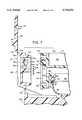
- FIG. 7is a greatly enlarged exploded fragmentary section of the front of the housing showing the front end parts prior to assembly;
- FIG. 12is a perspective exploded view of the modified form showing various parts of the housing including some of the parts which attach the housing to a container, and the bellows;
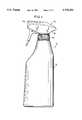
- FIG. 1A complete dispenser embodying the invention is shown in FIG. 1 and generally designated 10. It comprises a container 12 having a threaded finish 14 (FIG. 2). Usually the container will be blow-molded polyethylene. Other container shapes are, of course, envisioned.
- a resilient bowl-shaped bellows 46(FIG. 7) is provided and has an inward enlargement 48 around its mouth.
- the rim 40is deformed outward to clamp the enlargement 48 in position.
- An outward rib 50 on the bellowsfits against the shoulder 44 and the lower end of wall 42 is staked in at 52 to secure the bellows.
- the downward annular support wall 54(FIG. 2) serrated at its lower end. It concentrically circumposes the vertical tube 36.
- the wall 54is formed with a longitudinal slot 56 from its lower end facing the front of the housing. Inward of the wall 54 is a short concentric annular seal stabilizing wall 58.
- a vent seal 82is provided and formed with an outward peripheral outward flange 84 at its upper end (FIG. 6).
- the sealwhich may be made of a resilient elastic material, has a tubular body with an outward lip 86 at its lower end adapted to engage about the inside of the wall 64 below the slot 65.
- the sealis also formed with a laterally outward nose 88 which has a beveled-off end so that its upper end extends out from the body of the seal farther than the upper end.
- vent seal 82In assembly the vent seal 82 is inserted into the wall 64 (FIG. 2) and receives stabilizing wall 58. In further assembly as described already, the wall 54 is brought down over the wall 64. Serrations as shown help hold the parts together.
- the slots 56 and 65 in walls 54 and 64are aligned and provide ample passage of the radial nose 88. Nose 88 extends out beyond the wall of the boss 50 as shown in FIG. 2.
- the intermediate wall 32clamps the seal flange 84 against the top of the wall 64.
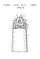
- the plate 120has door 133 attached to it by means of an integral "living" hinge 134.
- the front of the plate 120is formed with forwardly projecting sides 136 (only one shown in FIG. 7) to form a door-receiving recess and retainer.
- the top of the recessis beveled as at 138 and the door is complimentary shaped as at 140.
- the dooris formed with a sealing bump 142 and a hold-open head 144.
- the door 133has two extreme positions. In one the door 133 may be hinged all the way back against the top wall 26 (FIG. 2) so that the head 144 snaps into recess 28 thereby holding the door in the open position. In the other, the door 133 may be brought down so that it wedges or snaps between the side walls 136 in the door-receiving recess. The sealing bump 142 in this position closes the orifice 130 and seals it.
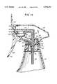
- dispenser 10' in the FIGS. 8-13 embodimentcomprises the container 12' having the threaded finish 14' to which is secured the trigger sprayer 16'.
- a cup-shaped mounting piece 210is fitted onto the lower end of the annular wall 208.
- the lower end of the wall 208may have an outward peripheral nib as shown and the inside surface of the cup-shaped piece 210 may have an undercut as shown, to achieve a snap-type installation.
- the cup-shaped mounting piece 210is formed with a central tubular spool or coupling, the upper part 76' of which fits into and mates with the downward extension 36'. These parts may carry nibs and undercuts for snap installation as with the piece 210 and wall 208. Intermediate its ends the coupling 70' is formed with a reduced internal diameter to define a seat 96'.
- Check ball 75'normally sits on the seat in the upper part 76' and prevents backflow. The ball check may rise with the discharge flow, its upward travel being stopped by the inward nibs as shown in the coupling and the downward stop 218 on the wall 202.
- a resilient discharge check valve disc 126'(FIG. 13) is disposed against the shoulder 110'.
- Resilient vent check disc 234is disposed against the rear face opening 232.
- the front component 22'is maneuvered so that ring 122' is inserted into the annular groove 106 and the nipple fits into opening 232.
- the stud 124'sandwiches the disc 126' between it and the shoulder 110' to form a check valve limiting a flow of liquid backward through the tube 34'.
- the vent nipple 230squeezes a lower portion of the check disc 234 against the bottom of the angled rear face of opening 232.
- the door 133'has two extreme positions. In one, the door 133' may be hinged folded all the way back against the top of the housing so that the head 144' snap into a recesses 28' in the housing (FIG. 11). This holds the door in the open position. In the other, the door 133' may be brought down so that it wedges between the side walls 136' in the door-receiving recess and the head 240 snaps into the socket in the front end of the passage through nipple 230. The sealing bump 142' in this position closes the discharge orifice 130' and seals it.
Landscapes
- Containers And Packaging Bodies Having A Special Means To Remove Contents (AREA)
- Closures For Containers (AREA)
- Agricultural Chemicals And Associated Chemicals (AREA)
- Nozzles (AREA)
- Reciprocating Pumps (AREA)
Abstract
Description
Claims (19)
Priority Applications (1)
| Application Number | Priority Date | Filing Date | Title |
|---|---|---|---|
| US08/768,096US5738251A (en) | 1993-12-11 | 1996-12-13 | Trigger sprayer |
Applications Claiming Priority (3)
| Application Number | Priority Date | Filing Date | Title |
|---|---|---|---|
| DE4342304ADE4342304A1 (en) | 1993-12-11 | 1993-12-11 | Spray pump |
| US08/352,146US5603434A (en) | 1993-12-11 | 1994-12-01 | Trigger sprayer |
| US08/768,096US5738251A (en) | 1993-12-11 | 1996-12-13 | Trigger sprayer |
Related Parent Applications (1)
| Application Number | Title | Priority Date | Filing Date |
|---|---|---|---|
| US08/352,146ContinuationUS5603434A (en) | 1993-12-11 | 1994-12-01 | Trigger sprayer |
Publications (1)
| Publication Number | Publication Date |
|---|---|
| US5738251Atrue US5738251A (en) | 1998-04-14 |
Family
ID=6504763
Family Applications (2)
| Application Number | Title | Priority Date | Filing Date |
|---|---|---|---|
| US08/352,146Expired - LifetimeUS5603434A (en) | 1993-12-11 | 1994-12-01 | Trigger sprayer |
| US08/768,096Expired - LifetimeUS5738251A (en) | 1993-12-11 | 1996-12-13 | Trigger sprayer |
Family Applications Before (1)
| Application Number | Title | Priority Date | Filing Date |
|---|---|---|---|
| US08/352,146Expired - LifetimeUS5603434A (en) | 1993-12-11 | 1994-12-01 | Trigger sprayer |
Country Status (6)
| Country | Link |
|---|---|
| US (2) | US5603434A (en) |
| EP (2) | EP0911083B1 (en) |
| JP (1) | JP3691095B2 (en) |
| AT (2) | ATE220573T1 (en) |
| CA (1) | CA2137532A1 (en) |
| DE (3) | DE4342304A1 (en) |
Cited By (21)
| Publication number | Priority date | Publication date | Assignee | Title |
|---|---|---|---|---|
| US5873496A (en)* | 1996-12-18 | 1999-02-23 | Monturas, S.A. | Assembly for non-removably fixing a closure cap to a dispenser body |
| USD419875S (en)* | 1998-07-16 | 2000-02-01 | Calmar Inc. | Sprayer shroud |
| USD420914S (en)* | 1999-04-30 | 2000-02-22 | Colgate-Palmolive Company | Pump head |
| USD424939S (en)* | 1999-07-29 | 2000-05-16 | Owens-Illinois Closure Inc. | Trigger sprayer |
| US6244473B1 (en)* | 1999-12-17 | 2001-06-12 | Owens-Illinois Closure Inc. | Pump dispenser having vent valve |
| US6257461B1 (en)* | 1998-03-25 | 2001-07-10 | Ing. Erich Pfeiffer Gmbh | Media dispenser having parts with shear faces for facilitating assembly |
| USD447415S1 (en) | 2000-05-31 | 2001-09-04 | Tolco Corporation | Trigger sprayer |
| USD451388S1 (en) | 2000-07-13 | 2001-12-04 | Tolco Corporation | Trigger sprayer |
| US20030213817A1 (en)* | 1995-04-10 | 2003-11-20 | Dispensing Patents International Llc | Spray dispensing device with nozzle closure |
| US7032841B1 (en)* | 2004-04-27 | 2006-04-25 | Swisher Steven L | Hand-held battery power sprayer |
| USD519836S1 (en)* | 2004-06-23 | 2006-05-02 | Swisher Steven L | Hand held, battery powered sprayer |
| US20060096149A1 (en)* | 2004-11-10 | 2006-05-11 | Wooden James D | Telescopic sight adjustment device |
| US20080083368A1 (en)* | 2006-10-06 | 2008-04-10 | Ward Jimmie C | Tire protectant applicator |
| US20090294480A1 (en)* | 2006-05-16 | 2009-12-03 | Seaquist Perfect Dispensing Gmbh | Dispensing device |
| US20100219207A1 (en)* | 2009-02-27 | 2010-09-02 | Seaquist Perfect Dispensing Gmbh | Lever spray pump |
| US20100252577A1 (en)* | 2006-06-08 | 2010-10-07 | Seaquist Perfect Dispensing Gmbh | Dispensing device |
| USD651089S1 (en)* | 2010-09-15 | 2011-12-27 | Monster Cable Products, Inc. | Spray bottle |
| US20170227269A1 (en)* | 2016-02-04 | 2017-08-10 | Wenling Jennfeng Industry Inc. | Freon Refilling Apparatus for Vehicles |
| US10159997B2 (en) | 2009-11-30 | 2018-12-25 | Silgan Dispensing Systems Corporation | Low cost trigger sprayer |
| USD880298S1 (en) | 2018-08-27 | 2020-04-07 | S. C. Johnson & Son, Inc. | Actuator |
| US11034507B2 (en) | 2018-08-27 | 2021-06-15 | S. C. Johnson & Son, Inc. | Trigger overcap assembly |
Families Citing this family (18)
| Publication number | Priority date | Publication date | Assignee | Title |
|---|---|---|---|---|
| JP3566368B2 (en)* | 1994-12-09 | 2004-09-15 | 株式会社吉野工業所 | Spring member of trigger sprayer |
| US6247613B1 (en)* | 1995-04-10 | 2001-06-19 | Philip Meshberg | Spray dispensing device with nozzle closure |
| US6739481B2 (en)* | 1995-04-10 | 2004-05-25 | Dispensing Patents International Llc | Spray dispensing device with nozzle closure |
| US5794822A (en)* | 1996-04-17 | 1998-08-18 | Contico International, Inc. | Reciprocating fluid pump with improved bottle seal |
| HUP0003502A3 (en) | 1997-09-04 | 2002-02-28 | Schuckmann Alfred | Spray pump capable of being actuated by a hand lever |
| US6032834A (en)* | 1998-10-22 | 2000-03-07 | Owens-Illinois Closure Inc. | Pump dispenser and method of making it |
| DE19916643A1 (en)* | 1999-04-14 | 2000-10-19 | Andreas Czech | Spray head for bottle has radial spray channels, fastening portion and seal which can be released by pressure on head, producing spray |
| US6286727B1 (en) | 2000-05-04 | 2001-09-11 | Owens-Illinois Closure Inc. | Pump dispenser having ergonomic overhang and method of making it |
| US6554211B1 (en)* | 2002-08-01 | 2003-04-29 | Saint-Gobain Calmar Inc. | Container vent control for battery operated sprayer |
| US7175111B2 (en)* | 2004-03-03 | 2007-02-13 | Meadwestvaco Corporation | Discharge/vent module for power sprayer |
| WO2006113685A2 (en)* | 2005-04-20 | 2006-10-26 | Dispensing Patents International, Llc | Spray dispensing device with nozzle closure |
| US7303150B2 (en)* | 2005-11-22 | 2007-12-04 | Meadwestvaco Corporation | Foam and spray nozzles having a hinged door and a trigger dispenser incorporating same |
| US20070132149A1 (en)* | 2005-11-29 | 2007-06-14 | Hildebrand George R | Methods of making foam nozzles for trigger dispensers |
| US7455198B2 (en)* | 2006-03-07 | 2008-11-25 | Meadwestvaco Calmar, Inc. | Trigger forward pivot limit for a trigger sprayer |
| US7891588B2 (en)* | 2006-05-31 | 2011-02-22 | Wagner Spray Tech Corporation | Quick disconnect for wetted parts in a paint spray gun |
| US8444019B2 (en) | 2009-08-07 | 2013-05-21 | Ecolab Usa Inc. | Wipe and seal product pump |
| CN107690412B (en) | 2015-04-06 | 2020-05-05 | 约翰逊父子公司 | distribution system |
| EP3774070A4 (en)* | 2018-04-13 | 2021-12-29 | Rieke LLC | Recyclable, pre-compression dispenser with trigger sprayer |
Citations (19)
| Publication number | Priority date | Publication date | Assignee | Title |
|---|---|---|---|---|
| US3726442A (en)* | 1971-02-17 | 1973-04-10 | Polypump Curacao Nv | Trigger pump and breather valve dispensing assembly |
| US3897006A (en)* | 1974-09-09 | 1975-07-29 | Tetsuya Tada | Sprayer |
| US3973700A (en)* | 1975-09-29 | 1976-08-10 | Schmidt Edward C | Bellows pump with extension having integral valves |
| US3986644A (en)* | 1975-05-21 | 1976-10-19 | Diamond International Corporation | Dispensing pump |
| US4101057A (en)* | 1976-12-02 | 1978-07-18 | Ethyl Corporation | Trigger actuated pump |
| US4138038A (en)* | 1977-07-21 | 1979-02-06 | Diamond International Corporation | Dispensing pump housing and operating lever assembly |
| US4155487A (en)* | 1977-09-09 | 1979-05-22 | Blake William S | Trigger sprayer |
| US4204614A (en)* | 1978-09-28 | 1980-05-27 | Diamond International Corporation | Fluid dispenser having a spring biased locking mechanism for a safety nozzle cap |
| USD256271S (en) | 1978-05-31 | 1980-08-05 | Tetsuya Tada | Sprayer |
| US4230277A (en)* | 1977-03-02 | 1980-10-28 | Tetsuya Tada | Trigger type sprayer with integrally formed locking nozzle cover |
| FR2461530A2 (en)* | 1979-07-16 | 1981-02-06 | Afa Corp | Hand-operated spray gun for pumping liq. out of a receptacle - has pump chamber and elastically-recovering bellows of PVC, EVA polyolefin polyester, rubber and/or polyurethane |
| US4558821A (en)* | 1983-03-03 | 1985-12-17 | Canyon Corporation | Trigger-type sprayer with integrally formed housing, trigger, nozzle and cylinder |
| US4898307A (en)* | 1988-08-25 | 1990-02-06 | Goody Products, Inc. | Spray caps |
| US4958754A (en)* | 1989-03-01 | 1990-09-25 | Continental Sprayers, Inc. | Dispenser or sprayer with vent system |
| US5114052A (en)* | 1988-08-25 | 1992-05-19 | Goody Products, Inc. | Manually actuated trigger sprayer |
| US5158233A (en)* | 1991-10-07 | 1992-10-27 | Contico International, Inc. | Foamer trigger dispenser with sealing device |
| USD332392S (en) | 1990-05-30 | 1993-01-12 | Contico International, Inc. | Sprayer bottle |
| WO1993017956A1 (en)* | 1992-03-09 | 1993-09-16 | Contico International, Inc. | Improved trigger sprayer apparatus |
| US5303867A (en)* | 1993-06-24 | 1994-04-19 | The Procter & Gamble Company | Trigger operated fluid dispensing device |
- 1993
- 1993-12-11DEDE4342304Apatent/DE4342304A1/ennot_activeWithdrawn
- 1994
- 1994-12-01USUS08/352,146patent/US5603434A/ennot_activeExpired - Lifetime
- 1994-12-07DEDE69420828Tpatent/DE69420828T2/ennot_activeExpired - Fee Related
- 1994-12-07EPEP99100631Apatent/EP0911083B1/ennot_activeExpired - Lifetime
- 1994-12-07EPEP94119355Apatent/EP0662350B1/ennot_activeExpired - Lifetime
- 1994-12-07ATAT99100631Tpatent/ATE220573T1/enactive
- 1994-12-07CACA002137532Apatent/CA2137532A1/ennot_activeAbandoned
- 1994-12-07DEDE69431004Tpatent/DE69431004T2/ennot_activeExpired - Fee Related
- 1994-12-07ATAT94119355Tpatent/ATE184811T1/ennot_activeIP Right Cessation
- 1994-12-12JPJP33136894Apatent/JP3691095B2/ennot_activeExpired - Fee Related
- 1996
- 1996-12-13USUS08/768,096patent/US5738251A/ennot_activeExpired - Lifetime
Patent Citations (20)
| Publication number | Priority date | Publication date | Assignee | Title |
|---|---|---|---|---|
| US3726442A (en)* | 1971-02-17 | 1973-04-10 | Polypump Curacao Nv | Trigger pump and breather valve dispensing assembly |
| US3897006A (en)* | 1974-09-09 | 1975-07-29 | Tetsuya Tada | Sprayer |
| US3986644A (en)* | 1975-05-21 | 1976-10-19 | Diamond International Corporation | Dispensing pump |
| US3973700A (en)* | 1975-09-29 | 1976-08-10 | Schmidt Edward C | Bellows pump with extension having integral valves |
| US4101057A (en)* | 1976-12-02 | 1978-07-18 | Ethyl Corporation | Trigger actuated pump |
| US4230277A (en)* | 1977-03-02 | 1980-10-28 | Tetsuya Tada | Trigger type sprayer with integrally formed locking nozzle cover |
| US4138038A (en)* | 1977-07-21 | 1979-02-06 | Diamond International Corporation | Dispensing pump housing and operating lever assembly |
| US4155487A (en)* | 1977-09-09 | 1979-05-22 | Blake William S | Trigger sprayer |
| USD256271S (en) | 1978-05-31 | 1980-08-05 | Tetsuya Tada | Sprayer |
| US4204614A (en)* | 1978-09-28 | 1980-05-27 | Diamond International Corporation | Fluid dispenser having a spring biased locking mechanism for a safety nozzle cap |
| FR2461530A2 (en)* | 1979-07-16 | 1981-02-06 | Afa Corp | Hand-operated spray gun for pumping liq. out of a receptacle - has pump chamber and elastically-recovering bellows of PVC, EVA polyolefin polyester, rubber and/or polyurethane |
| US4558821A (en)* | 1983-03-03 | 1985-12-17 | Canyon Corporation | Trigger-type sprayer with integrally formed housing, trigger, nozzle and cylinder |
| US4898307A (en)* | 1988-08-25 | 1990-02-06 | Goody Products, Inc. | Spray caps |
| US5114052A (en)* | 1988-08-25 | 1992-05-19 | Goody Products, Inc. | Manually actuated trigger sprayer |
| US4958754A (en)* | 1989-03-01 | 1990-09-25 | Continental Sprayers, Inc. | Dispenser or sprayer with vent system |
| USD332392S (en) | 1990-05-30 | 1993-01-12 | Contico International, Inc. | Sprayer bottle |
| US5158233A (en)* | 1991-10-07 | 1992-10-27 | Contico International, Inc. | Foamer trigger dispenser with sealing device |
| WO1993017956A1 (en)* | 1992-03-09 | 1993-09-16 | Contico International, Inc. | Improved trigger sprayer apparatus |
| US5294025A (en)* | 1992-03-09 | 1994-03-15 | Contico | Pump trigger assembly for a trigger spray |
| US5303867A (en)* | 1993-06-24 | 1994-04-19 | The Procter & Gamble Company | Trigger operated fluid dispensing device |
Cited By (28)
| Publication number | Priority date | Publication date | Assignee | Title |
|---|---|---|---|---|
| US20030213817A1 (en)* | 1995-04-10 | 2003-11-20 | Dispensing Patents International Llc | Spray dispensing device with nozzle closure |
| US6817488B2 (en)* | 1995-04-10 | 2004-11-16 | Dispensing Patents International Llc | Spray dispensing device with nozzle closure |
| US5873496A (en)* | 1996-12-18 | 1999-02-23 | Monturas, S.A. | Assembly for non-removably fixing a closure cap to a dispenser body |
| US6257461B1 (en)* | 1998-03-25 | 2001-07-10 | Ing. Erich Pfeiffer Gmbh | Media dispenser having parts with shear faces for facilitating assembly |
| USD419875S (en)* | 1998-07-16 | 2000-02-01 | Calmar Inc. | Sprayer shroud |
| USD420914S (en)* | 1999-04-30 | 2000-02-22 | Colgate-Palmolive Company | Pump head |
| USD424939S (en)* | 1999-07-29 | 2000-05-16 | Owens-Illinois Closure Inc. | Trigger sprayer |
| US6425501B1 (en)* | 1999-12-17 | 2002-07-30 | Owens-Llinois Closure Inc. | Pump dispenser having vent valve |
| US6244473B1 (en)* | 1999-12-17 | 2001-06-12 | Owens-Illinois Closure Inc. | Pump dispenser having vent valve |
| USD447415S1 (en) | 2000-05-31 | 2001-09-04 | Tolco Corporation | Trigger sprayer |
| USD451388S1 (en) | 2000-07-13 | 2001-12-04 | Tolco Corporation | Trigger sprayer |
| US7032841B1 (en)* | 2004-04-27 | 2006-04-25 | Swisher Steven L | Hand-held battery power sprayer |
| USD519836S1 (en)* | 2004-06-23 | 2006-05-02 | Swisher Steven L | Hand held, battery powered sprayer |
| US7246461B2 (en) | 2004-11-10 | 2007-07-24 | James Dale Wooden | Telescopic sight adjustment device |
| US20060096149A1 (en)* | 2004-11-10 | 2006-05-11 | Wooden James D | Telescopic sight adjustment device |
| US20090294480A1 (en)* | 2006-05-16 | 2009-12-03 | Seaquist Perfect Dispensing Gmbh | Dispensing device |
| US8573449B2 (en)* | 2006-06-08 | 2013-11-05 | Aptar Dortmund Gmbh | Dispensing device having an elastically deformable section for pumping a fluid |
| US20100252577A1 (en)* | 2006-06-08 | 2010-10-07 | Seaquist Perfect Dispensing Gmbh | Dispensing device |
| US20080083368A1 (en)* | 2006-10-06 | 2008-04-10 | Ward Jimmie C | Tire protectant applicator |
| US8365962B2 (en)* | 2009-02-27 | 2013-02-05 | Aptar Dortmund Gmbh | Lever spray pump |
| US20100219207A1 (en)* | 2009-02-27 | 2010-09-02 | Seaquist Perfect Dispensing Gmbh | Lever spray pump |
| US10159997B2 (en) | 2009-11-30 | 2018-12-25 | Silgan Dispensing Systems Corporation | Low cost trigger sprayer |
| USD651089S1 (en)* | 2010-09-15 | 2011-12-27 | Monster Cable Products, Inc. | Spray bottle |
| US20170227269A1 (en)* | 2016-02-04 | 2017-08-10 | Wenling Jennfeng Industry Inc. | Freon Refilling Apparatus for Vehicles |
| USD880298S1 (en) | 2018-08-27 | 2020-04-07 | S. C. Johnson & Son, Inc. | Actuator |
| USD908491S1 (en) | 2018-08-27 | 2021-01-26 | S. C. Johnson & Son, Inc. | Actuator |
| US11034507B2 (en) | 2018-08-27 | 2021-06-15 | S. C. Johnson & Son, Inc. | Trigger overcap assembly |
| US11708210B2 (en) | 2018-08-27 | 2023-07-25 | S. C. Johnson & Son, Inc. | Trigger overcap assembly |
Also Published As
| Publication number | Publication date |
|---|---|
| EP0911083B1 (en) | 2002-07-17 |
| EP0662350A3 (en) | 1995-09-20 |
| DE69431004D1 (en) | 2002-08-22 |
| EP0662350B1 (en) | 1999-09-22 |
| DE4342304A1 (en) | 1995-06-14 |
| JPH07251105A (en) | 1995-10-03 |
| DE69420828T2 (en) | 2000-04-20 |
| EP0911083A2 (en) | 1999-04-28 |
| EP0662350A2 (en) | 1995-07-12 |
| ATE184811T1 (en) | 1999-10-15 |
| EP0911083A3 (en) | 1999-08-11 |
| ATE220573T1 (en) | 2002-08-15 |
| DE69420828D1 (en) | 1999-10-28 |
| US5603434A (en) | 1997-02-18 |
| CA2137532A1 (en) | 1995-06-12 |
| JP3691095B2 (en) | 2005-08-31 |
| DE69431004T2 (en) | 2003-03-13 |
Similar Documents
| Publication | Publication Date | Title |
|---|---|---|
| US5738251A (en) | Trigger sprayer | |
| US5507437A (en) | Low cost trigger sprayer having housing with integral saddle | |
| EP0850695B1 (en) | Dispensers for liquid products | |
| US5553752A (en) | Spring for trigger sprayer | |
| US5938082A (en) | Container assembly having snap-fit container connection | |
| US4489890A (en) | Hand-operated pump | |
| US4982900A (en) | Trigger sprayer | |
| US5423460A (en) | Spray pump | |
| US4033487A (en) | Double trigger pump | |
| US5906301A (en) | Radially expanding tube valve in a liquid dispenser | |
| US4480768A (en) | Hand-operated pump | |
| US5575407A (en) | Low cost trigger sprayer having container with integral saddle | |
| US5887763A (en) | Reciprocating fluid pump with bottle closure having inner and outer rim seals | |
| EP0098508B1 (en) | Trigger sprayer |
Legal Events
| Date | Code | Title | Description |
|---|---|---|---|
| STCF | Information on status: patent grant | Free format text:PATENTED CASE | |
| FPAY | Fee payment | Year of fee payment:4 | |
| AS | Assignment | Owner name:CONTINENTALAFA DISPENSING COMPANY, MISSOURI Free format text:CORRECTIV;ASSIGNOR:OWENS ILLINOIS CLOSURE, INC.;REEL/FRAME:015886/0892 Effective date:20031107 | |
| AS | Assignment | Owner name:OAK HILL SECURITIES FUND, L.P., NEW YORK Free format text:ASSIGNMENT FOR SECURITY;ASSIGNORS:CONTINENTALAFA DISPENSING COMPANY;AFA PRODUCTS INC.;CONTINENTAL SPRAYERS INTERNATIONAL INC.;AND OTHERS;REEL/FRAME:014146/0907 Effective date:20031112 Owner name:OAK HILL SECURITIES FUND, L.P.,NEW YORK Free format text:ASSIGNMENT FOR SECURITY;ASSIGNORS:CONTINENTALAFA DISPENSING COMPANY;AFA PRODUCTS INC.;CONTINENTAL SPRAYERS INTERNATIONAL INC.;AND OTHERS;REEL/FRAME:014146/0907 Effective date:20031112 | |
| FEPP | Fee payment procedure | Free format text:PAYOR NUMBER ASSIGNED (ORIGINAL EVENT CODE: ASPN); ENTITY STATUS OF PATENT OWNER: LARGE ENTITY | |
| FPAY | Fee payment | Year of fee payment:8 | |
| AS | Assignment | Owner name:CONTINENTALAFA DISPENSING COMPANY,MISSOURI Free format text:TERMINATION OF SECURITY INTEREST AND RELEASE OF CO;ASSIGNOR:OAK HILL SECURITIES FUND, L.P.;REEL/FRAME:019331/0617 Effective date:20050715 Owner name:AFA PRODUCTS, INC., DELAWARE CORPORATION,NORTH CAR Free format text:TERMINATION OF SECURITY INTEREST AND RELEASE OF CO;ASSIGNOR:OAK HILL SECURITIES FUND, L.P.;REEL/FRAME:019331/0617 Effective date:20050715 Owner name:AFA PRODUCTS, INC., DELAWARE CORPORATION, NORTH CA Free format text:TERMINATION OF SECURITY INTEREST AND RELEASE OF CO;ASSIGNOR:OAK HILL SECURITIES FUND, L.P.;REEL/FRAME:019331/0617 Effective date:20050715 Owner name:CONTINENTALAFA DISPENSING COMPANY, MISSOURI Free format text:TERMINATION OF SECURITY INTEREST AND RELEASE OF CO;ASSIGNOR:OAK HILL SECURITIES FUND, L.P.;REEL/FRAME:019331/0617 Effective date:20050715 Owner name:CONTINENTAL SPRAYERS INTERNATIONAL, INC., A DELAWA Free format text:TERMINATION OF SECURITY INTEREST AND RELEASE OF CO;ASSIGNOR:OAK HILL SECURITIES FUND, L.P.;REEL/FRAME:019331/0617 Effective date:20050715 | |
| AS | Assignment | Owner name:THE CIT GROUP/BUSINESS CREDIT, INC. AS COLLATERAL Free format text:SECURITY AGREEMENT;ASSIGNOR:CONTINENTALAFA DISPENSING COMPANY;REEL/FRAME:016722/0012 Effective date:20050715 | |
| AS | Assignment | Owner name:THE CIT GROUP/BUSINESS CREDIT, INC. AS COLLATERAL Free format text:SECURITY AGREEMENT;ASSIGNOR:CONTINENTALAFA DISPENSING COMPANY;REEL/FRAME:016722/0349 Effective date:20050715 | |
| AS | Assignment | Owner name:OWENS-ILLINOIS CLOSURE INC., OHIO Free format text:ASSIGNMENT OF ASSIGNORS INTEREST;ASSIGNOR:VON SCHUCKMANN, ALFRED;REEL/FRAME:016793/0294 Effective date:19941109 | |
| AS | Assignment | Owner name:CONTINENTALAFA DISPENSING COMPANY,MISSOURI Free format text:RELEASE OF SECURITY INTEREST IN PATENTS AS RECORDED ON 11/2/2005 AT REEL 016722, FRAME 0012 AND ON 11/3/2005 REEL 016722, FRAME 0349;ASSIGNOR:THE CIT GROUP/ BUSINESS CREDIT, INC;REEL/FRAME:019362/0565 Effective date:20070515 Owner name:CONTINENTALAFA DISPENSING COMPANY, MISSOURI Free format text:RELEASE OF SECURITY INTEREST IN PATENTS AS RECORDED ON 11/2/2005 AT REEL 016722, FRAME 0012 AND ON 11/3/2005 REEL 016722, FRAME 0349;ASSIGNOR:THE CIT GROUP/ BUSINESS CREDIT, INC;REEL/FRAME:019362/0565 Effective date:20070515 | |
| AS | Assignment | Owner name:WACHOVIA CAPITAL FINANCE CORPORATION (CENTRAL),ILL Free format text:SECURITY AGREEMENT;ASSIGNOR:CONTINENTALAFA DISPENSING COMPANY;REEL/FRAME:019399/0087 Effective date:20070515 Owner name:WACHOVIA CAPITAL FINANCE CORPORATION (CENTRAL), IL Free format text:SECURITY AGREEMENT;ASSIGNOR:CONTINENTALAFA DISPENSING COMPANY;REEL/FRAME:019399/0087 Effective date:20070515 | |
| AS | Assignment | Owner name:HARBINGER CAPITAL PARTNERS MASTER FUND I, LTD.,NEW Free format text:PATENT COLLATERAL ASSIGNMENT AND SECURITY AGREEMENT;ASSIGNOR:CONTINENTALAFA DISPENSING COMPANY;REEL/FRAME:019432/0235 Effective date:20070515 Owner name:HARBINGER CAPITAL PARTNERS MASTER FUND I, LTD., NE Free format text:PATENT COLLATERAL ASSIGNMENT AND SECURITY AGREEMENT;ASSIGNOR:CONTINENTALAFA DISPENSING COMPANY;REEL/FRAME:019432/0235 Effective date:20070515 | |
| FPAY | Fee payment | Year of fee payment:12 | |
| AS | Assignment | Owner name:CONTINENTALAFA DISPENSING COMPANY, VIRGINIA Free format text:RELEASE BY SECURED PARTY;ASSIGNOR:WACHOVIA CAPITAL FINANCE CORPORATION (CENTRAL);REEL/FRAME:041511/0463 Effective date:20081016 | |
| AS | Assignment | Owner name:CONTINENTALAFA DISPENSING COMPANY, VIRGINIA Free format text:RELEASE BY SECURED PARTY;ASSIGNOR:HARBINGER CAPITAL PARTNERS MASTER FUND I, LTD.;REEL/FRAME:041518/0304 Effective date:20081015 |