US5737506A - Anatomical visualization system - Google Patents
Anatomical visualization systemDownload PDFInfo
- Publication number
- US5737506A US5737506AUS08/457,692US45769295AUS5737506AUS 5737506 AUS5737506 AUS 5737506AUS 45769295 AUS45769295 AUS 45769295AUS 5737506 AUS5737506 AUS 5737506A
- Authority
- US
- United States
- Prior art keywords
- software object
- database
- computer model
- slice
- image
- Prior art date
- Legal status (The legal status is an assumption and is not a legal conclusion. Google has not performed a legal analysis and makes no representation as to the accuracy of the status listed.)
- Expired - Lifetime
Links
Images


Classifications
- G—PHYSICS
- G06—COMPUTING OR CALCULATING; COUNTING
- G06T—IMAGE DATA PROCESSING OR GENERATION, IN GENERAL
- G06T17/00—Three dimensional [3D] modelling, e.g. data description of 3D objects
- G—PHYSICS
- G16—INFORMATION AND COMMUNICATION TECHNOLOGY [ICT] SPECIALLY ADAPTED FOR SPECIFIC APPLICATION FIELDS
- G16H—HEALTHCARE INFORMATICS, i.e. INFORMATION AND COMMUNICATION TECHNOLOGY [ICT] SPECIALLY ADAPTED FOR THE HANDLING OR PROCESSING OF MEDICAL OR HEALTHCARE DATA
- G16H30/00—ICT specially adapted for the handling or processing of medical images
- G16H30/20—ICT specially adapted for the handling or processing of medical images for handling medical images, e.g. DICOM, HL7 or PACS
Definitions
- This inventionrelates to medical apparatus in general, and more particularly to anatomical visualization systems.
- scanning devicestypically include CT scanners, MRI devices, X-ray machines, ultrasound devices and the like, and essentially serve to provide the physician with some sort of visualization of the patient's interior anatomical structure prior to commencing the actual medical procedure.
- the physiciancan then use this information to plan the medical procedure in advance, taking into account patient-specific anatomical structure.
- the physiciancan also use the information obtained from such preliminary scanning to more precisely identify the location of selected structures (e.g., tumors and the like) which may themselves be located within the interior of internal organs or other internal body structures. As a result, the physician can more easily "zero in” on such selected structures during the subsequent medical procedure. Furthermore, in many cases, the anatomical structures of interest to the physician may be quite small and/or difficult to identify with the naked eye. In these situations, preliminary scanning of the patient's interior anatomical structure using high resolution scanning devices can help the physician locate the structures of interest during the subsequent medical procedure.
- selected structurese.g., tumors and the like
- scanning devices of the sort described abovetend to generate two-dimensional (i.e., "2-D") images of the patient's anatomical structure.
- the scanning devicesare adapted to provide a set of 2-D images, with each 2-D image in the set being related to every other 2-D image in the set according to some pre-determined relationship.
- CT scannerstypically generate a series of 2-D images, with each 2-D image corresponding to a specific plane or "slice" taken through the patient's anatomical structure.
- each image plane or slicemay be set parallel to every other image plane or slice, and adjacent image planes or slices may be spaced a pre-determined distance apart.
- the parallel image planesmight be set 1 mm apart.
- the physiciancan view each 2-D image individually and, by viewing a series of 2-D images in proper sequence, can mentally generate a three-dimensional (i.e., "3-D") impression of the patient's interior anatomical structure.
- Some scanning devicesinclude, as part of their basic system, associated computer hardware and software for building a 3-D database of the patient's scanned anatomical structure using a plurality of the aforementioned 2-D images.
- some CT and MRI scannersinclude such associated computer hardware and software as part of their basic system.
- such associated computer hardware and softwaremay be provided independently of the scanning devices, as a sort of "add-on" to the system; in this case, the data from the scanned 2-D images is fed from the scanning device to the associated computer hardware and software in a separate step.
- a trained operator using the scanning devicecan create a set of scanned 2-D images, assemble the data from these scanned 2-D images into a 3-D database of the scanned anatomical structure, and then generate various additional images of the scanned anatomical structure using the 3-D database.
- This featureis a very powerful tool, since it essentially permits a physician to view the patient's scanned anatomical structure from a wide variety of different viewing positions. As a result, the physician's understanding of the patient's scanned anatomical structure is generally greatly enhanced.
- each scanned 2-D slice imageis displayed as a separate and distinct image, and each image generated from the 3-D database is displayed as a separate and distinct image.
- physicianscan sometimes have difficulty correlating what they see on a particular scanned 2-D slice image with what they see on a particular image generated from the 3-D database.
- one object of the present inventionis to provide an improved anatomical visualization system wherein a scanned 2-D slice image can be appropriately combined with an image generated from a 3-D database so as to create a single composite image.
- Another object of the present inventionis to provide an improved anatomical visualization system wherein a marker can be placed onto a 2-D slice image displayed on a screen, and this marker will be automatically incorporated, as appropriate, into a 3-D computer model maintained by the system, as well as into any other 2-D slice image data maintained by the system.
- Still another object of the present inventionis to provide an improved anatomical visualization system wherein a margin of pre-determined size can be associated with a marker of the sort described above, and further wherein the margin will be automatically incorporated into the 3-D computer model, and into any other 2-D slice image data, in association with that marker.
- Yet another object of the present inventionis to provide an improved anatomical visualization system wherein the periphery of objects contained in a 3-D computer model maintained by the system can be automatically identified in any 2-D slice image data maintained by the system, wherein the periphery of such objects can be highlighted as appropriate in 2-D slice images displayed by the system.
- Yet another object of the present inventionis to provide an improved method for visualizing anatomical structure.
- a visualization systemcomprising a first database that comprises a plurality of 2-D slice images generated by scanning a structure.
- the 2-D slice imagesare stored in a first data format.
- a second databaseis also provided that comprises a 3-D computer model of the scanned structure.
- the 3-D computer modelcomprises a first software object that is defined by a 3-D geometry database.
- Meansare provided for inserting a second software object into the 3-D computer model so as to augment the 3-D computer model.
- the second software objectis also defined by a 3-D geometry database, and includes a planar surface.
- Means for determining the specific 2-D slice image associated with the position of the planar surface of the second software object within the augmented 3-D computer modelare provided in a preferred embodiment of the invention.
- Meansare also provided for texture mapping the specific 2-D slice image onto the planar surface of the second software object.
- Display meansare provided for displaying an image of the augmented 3-D computer model so as to simultaneously provide a view of the first software object and the specific 2-D slice image texture mapped onto the planar surface of the second software object.
- a visualization systemcomprising a first database comprising a plurality of 2-D slice images generated by scanning a structure.
- the 2-D slice imagesare again stored in a first data format.
- a second databasecomprising a 3-D computer model of the scanned structure is also provided in which the 3-D computer model comprises a first software object that is defined by a 3-D geometry database.
- Meansare provided for selecting a particular 2-D slice image from the first database.
- Meansare also provided for inserting a second software object into the 3-D computer model so as to augment the 3-D computer model.
- the second software objectis defined by a 3-D geometry database, and also includes a planar surface.
- the second software objectis inserted into the 3-D computer model at the position corresponding to the position of the selected 2-D slice image relative to the scanned structure.
- Means for texture mapping the specific 2-D slice image onto the planar surface of the second software objectare also provided.
- Meansare provided for displaying an image of the augmented 3-D computer model so as to simultaneously provide a view of the first software object and the specific 2-D slice image texture mapped onto the planar surface of the second software object.
- the 3-D geometry databasemay comprise a surface model.
- the systemmay further comprise means for inserting a marker into the first database, whereby the marker will be automatically incorporated into the second database, and further wherein the marker will be automatically displayed where appropriate in any image displayed by the system.
- the systemmay further comprise a margin of pre-determined size associated with the marker.
- the systemmay further comprise means for automatically determining the periphery of any objects contained in the second database and for identifying the corresponding data points in the first database, whereby the periphery of such objects can be highlighted as appropriate in any image displayed by the system.
- the scanned structurewill comprise an anatomical structure.
- the present inventionalso comprises a method for visualizing an anatomical structure.
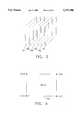
- FIG. 1is a schematic view showing a scanning device generating a set of 2-D images of the anatomy of a patient
- FIG. 2is a 2-D slice image corresponding to an axial slice taken through the abdomen of an individual
- FIG. 3shows a series of data frames corresponding to 2-D slice images arranged in a parallel array
- FIG. 4is a schematic view showing the scanning data contained within an exemplary data frame
- FIG. 5shows scanning data stored in a first storage device or medium being retrieved, processed and then stored again in a second data storage device or medium;
- FIG. 6is a schematic view of a system for retrieving and viewing scanning data
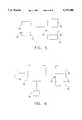
- FIG. 7is a schematic view of a unit cube for use in defining polygonal surface models
- FIG. 8illustrates the data file format of the polygonal surface model for the simple unit cube shown in FIG. 7;
- FIGS. 9A-9Fillustrate a variety of menu choices which may be utilized in connection with the present invention.
- FIG. 10illustrates an image drawn to a window using the data contained in the 3-D computer model associated with the present invention
- FIG. 11illustrates a 2-D slice image drawn to a window in accordance with the present invention
- FIG. 12illustrates a composite image formed from information contained in both the 3-D computer model and the 2-D image slice data structure
- FIG. 13is a schematic illustration showing the relationship between axial slices, sagittal slices and coronal slices
- FIG. 14illustrates three different 2-D slice images being displayed on a computer screen at the same time, with a marker being incorporated into each of the images;
- FIG. 15illustrates a marker shown in an image generated from the 3-D computer model, with the marker being surrounded by a margin of pre-determined size
- FIG. 16illustrates a 2-D slice image, wherein the periphery of an object has been automatically highlighted by the system.
- a scanning device 5is shown as it scans the interior anatomical structure of a patient 10, as that patient 10 lies on a scanning platform 15.
- Scanning device 5is of the sort adapted to generate scanning data corresponding to a series of 2-D images, where each 2-D image corresponds to a specific viewing plane or "slice" taken through the patient's body. Furthermore, scanning device 5 is adapted so that the angle and spacing between adjacent image planes or slices can be very well defined, e.g., each image plane or slice may be set parallel to every other image plane or slice, and adjacent image planes or slices may be spaced a pre-determined distance apart. By way of example, the parallel image planes might be set 1 mm apart.
- the scanning data obtained by scanning device 5can be displayed as a 2-D slice image on a display 20, and/or it can be stored in its 2-D slice image data form in a first section 23 of a data storage device or medium 25. Furthermore, additional information associated with the scanning data (e.g. patient name, age, etc.) can be stored in a second section 27 of data storage device or medium 25.
- scanning device 5might comprise a CT scanner of the sort manufactured by GE Medical Systems of Milwaukee, Wis.
- a 2-D slice image of the sort generated by scanning device 5 and displayed on display 20might comprise the 2-D slice image shown in FIG. 2.
- the 2-D slice image showncorresponds to an axial slice taken through an individual's abdomen and showing, among other things, that individual's liver.
- Scanning device 5may format its scanning data in any one of a number of different data structures.
- scanning device 5might format its scanning data in the particular data format used by a CT scanner of the sort manufactured by GE Medical Systems of Milwaukee, Wis. More specifically, with such a scanning device, the scanning data is generally held as a series of data "frames", where each data frame corresponds to a particular 2-D slice image taken through the patient's body. Furthermore, within each data frame, the scanning data is generally organized so as to represent the scanned anatomical structure at a particular location within that 2-D slice image.
- Such a data structureis fairly common for scanning devices of the sort associated with the present invention. However, it should be appreciated that the present invention is not dependent on the particlar data format utilized by scanning device 5.
- the scanning data provided by scanning device 5can be formatted in almost any desired data structure, so long as that data structure is well defined, whereby the scanning data can be retrieved and utilized as will hereinafter be disclosed in further detail.
- FIG. 3a series of data frames 30A, 30B, 30C, etc. are shown arranged in a parallel array.
- Each of these data frames 30A, 30B, 30C, etc.corresponds to a particular 2-D slice image taken through the patient's body by scanning device 5, where the 2-D slice images are taken parallel to one another.
- adjacent image planes or slicesare spaced apart by a constant, predetermined distance, e.g., 1 mm.
- the scanning data contained within an exemplary data frame 30Ais shown represented in an X-Y coordinate scheme so as to quickly and easily identify the scanned anatomical structure disposed at a particular location within that 2-D slice image.
- the scanning data relating to a particular X-Y coordinaterepresents an image intensity value. This image intensity value generally reflects some attribute of the specific anatomical structure being scanned, e.g., the tissue density.
- the scanning data generated by scanning device 5is stored in its 2-D slice image data form in first section 23 of data storage device or medium 25, with the scanning data being stored in a particular data format as determined by the manufacturer of scanning device 5.
- the scanning data stored in first section 23 of data storage device or medium 25is retrieved, processed and then stored again in a data storage device or medium 30.
- the scanning data stored in first section 23 of data storage device or medium 25is retrieved and processed so as to convert the scanning data generated by scanning device 5 from its 2-D slice image data form into a 3-D computer model of the patient's anatomical structure.
- This 3-D computer modelis then stored in a first section 35 of data storage device or medium 30.
- the scanning data stored in first section 23 of data storage device or medium 25is retrieved and processed as necessary so as to convert the scanning data into a preferred data format for the 2-D slice image data.
- the 2-D slice image datais then stored in this preferred data format in second section 40 of data storage device or medium 30.
- the additional information associated with the scanning data(e.g. patient name, age, etc.) which was previously stored in second section 27 of data storage device or medium 25 can be stored in a third section 42 of data storage device or medium 30.
- the 3-D computer modelhas been stored in first section 35 of data storage device or medium 30, and the 2-D slice image data has been stored in a preferred data format in second section 40 of data storage device or medium 30, a physician can then use an appropriately programmed computer to access the 3-D computer model stored in first section 35 of data storage device or medium 30, and/or the 2-D slice image data stored in second section 40 of data storage device or medium 30, to generate desired patient-specific images.
- a physiciancan use an appropriately programmed computer 50, operated by input devices 55, to access the 3-D computer model stored in first section 35 of data storage device or medium 30, and/or the 2-D slice image data stored in second section 40 of data storage device or medium 30, so as to generate the desired patient-specific images and display those images on a display 60.
- the 3-D computer model contained in first section 35 of data storage device or medium 30is preferably structured as a collection of software objects, with each software object being defined by a polygonal surface model of the sort well known in the art.
- a scanned anatomical structuresuch as a human liver might be modeled as three distinct software objects, with the outer surface of the general mass of the liver being one software object, the outer surface of the vascular structure of the liver being a second software object, and the outer surface of a tumor located in the liver being a third software object.
- FIGS. 7 and 8illustrate a typical manner of defining a software object by a polygonal surface model.
- FIG. 7illustrates the vertices of a unit cube set in an X-Y-Z coordinate system
- FIG. 8illustrates the data file format of the polygonal surface model for this simple unit cube.
- more complex shapessuch as human anatomical structure can be expressed in corresponding terms.
- the 3-D computer model contained in first section 35 of data storage device or medium 30is created by analyzing the 2-D slice image data stored in first section 23 of data storage device or medium 25 using techniques well known in the art.
- the 2-D slice image data stored in first section 23 of data storage device or medium 25might be processed using the well known "Marching Cubes" algorithm, which is a so-called "brute force” surface construction algorithm that extracts isodensity surfaces from volume data, producing from one to five triangles within voxels that contain the surface.
- the 2-D slice image data stored in first section 23 of data storage device or medium 25might be processed into the 3-D computer model stored in first section 35 of data storage device or medium 30 by some other appropriate modelling algorithm so as to yield the desired 3-D computer model.
- the specific data structure used to store the 2-D slice image data in second section 40 of data storage device or medium 30will also depend on the specific nature of computer 50 and on the particular operating system and application software being run on computer 50.
- the 2-D slice image data contained in second section 40 of data storage device or medium 30is preferably structured as a series of data "frames", where each data frame corresponds to a particular 2-D slice image taken through the patient's body, and where the scanning data within each data frame is organized so as to represent the scanned anatomical structure at a particular location within that 2-D slice image.
- computer 50comprise a Power PC-based, Macintosh operating system ("Mac OS") type of computer, e.g. a Power PC Macintosh 8100/80 of the sort manufactured by Apple Computer, Inc. of Cupertino, Calif.
- Mac OSPower PC-based, Macintosh operating system
- computer 50be running Macintosh operating system software, e.g. Mac OS Ver. 7.5.1, such that computer 50 can readily access a 3-D computer model formatted in Apple's well-known QuickDraw 3D data format and display images generated from that 3D computer model, and such that computer 50 can readily access and display 2-D images formatted in Apple's well-known QuickTime image data format.
- Input devices 55preferably comprise the usual computer input devices associated with a Power PC-based, Macintosh operating system computer, e.g., input devices 55 preferably comprise a keyboard, a mouse, etc.
- the 3-D computer model contained in first section 35 of data storage device or medium 30be formatted in Apple's QuickDraw 3D data format, whereby the Mac OS computer 50 can quickly and easily access the 3-D computer model contained in first section 35 of data storage device or medium 30 and display images generated from that 3-D computer model on display 60.
- the 2-D slice image data contained in second section 40 of data storage device or medium 30be formatted in Apple's QuickTime image data format.
- computer 50can quickly and easily display the scanned 2-D slice images obtained by scanning device 5.
- scanning device 5happens to format its scanning data in the preferred QuickTime image data format
- no reformatting of the 2-D slice image datawill be necessary prior to storing the 2-D slice image data in second section 40 of data storage device or medium 30.
- reformatting of the 2-D slice image datawill be necessary so as to put it into the preferred QuickTime image data format.
- Such image data reformattingis of the sort well known in the art.
- a physician operating computer 50 through input devices 55can generate a desired image from the 3-D computer model contained within first section 35 of data storage device or medium 30.
- the physiciancan use input devices 55 to (1) open a window on display 60, (2) instruct the computer as to the desired angle of view, (3) generate the corresponding image of the scanned anatomical structure from the desired angle of view, using the 3-D computer model contained within first section 35 of data storage device or medium 30, and (4) display that image in the open window on display 60.
- a physician operating computer 50 through input devices 55can display a desired 2-D slice image from the 2-D slice image data contained within second section 40 of data storage device or medium 30.
- the physiciancan use input devices 55 to (1) open a window on display 60, (2) select a particular 2-D slice image contained within second section 40 of data storage device or medium 30, and (3) display that slice image in the open window on display 60.
- computer 50is preferably programmed so as to provide a variety of pre-determined menu choices which may be selected by the physician operating computer 50 via input devices 55.
- FIG. 10illustrates an image drawn to a window using the data contained in the 3-D computer model stored in first section 35 of data storage device or medium 30.
- the physiciancan use input devices 55 to instruct the image rendering software as to the particular angle of view desired.
- the physiciancan depress a mouse key and then drag on the object so as to rotate the object into the desired angle of view.
- the physiciancan use menu choices such as those shown in FIGS. 9A-9F to open a window on the display 60 to display a desired 2-D image slice from second section 40 of data storage device or medium 30 in that window.
- the physiciancan select between different image slices utilizing input devices 55.
- FIG. 11illustrates a 2-D image slice drawn to a window by the operating system using the data contained in second section 40 of data storage device or medium 30.
- icon 70By dragging icon 70 back and forth along slider 75, the physician can "leaf" back and forth through the collection of axial slices, i.e., in the example of FIG.
- dragging icon 70 to the leftmight cause axial slice #20 to be displayed, and dragging icon 70 to the right might cause axial slice #22 to be displayed.
- Menu commandscan also be provided to change the slice window display directly to the first or last slice image in the 2-D slice image set, or to change the slice window display to a user-specified slice number. Programming to effect such computer operation is of the sort well known in the art.
- the aforementioned image rendering softwarei.e., the Mac OS, the Apple QuickDraw 3D data format and software, and the Apple QuickTime image data format and software, or some equivalent hardware and software
- an additional software objectinto the 3-D computer model contained within first section 35 of data storage device or medium 30.
- the computer's image rendering softwareit is possible to texture map a 2-D slice image from second section 40 of data storage device or medium 30 onto the blank planar surface of the software object.
- both 3-D model structure and 2-D image slice structurecan be simultaneously displayed in proper registration with one another, thereby providing a single composite image of the two separate images. See, for example, FIG. 12, which shows such a composite image.
- the physiciancan use input devices 55 to instruct the operating system's image rendering software as to where the aforementioned "additional" software object is to be inserted into the model and as to the particular angle of view desired. Programming to effect such computer operation is of the sort well known in the art.
- the 2-D slice image data generated by scanning device 5has generally been discussed in the context of the standard "axial" slice images normally generated by scanning devices of the type associated with this invention. However, it is to be appreciated that it is also possible to practice the present invention in connection with sagittal or coronal 2-D slice images.
- scanning device 5will normally generate axial slice image data when scanning a patent.
- scanning device 5will also assemble the axial slice data into a 3-D database of the scanned anatomical structure, and then use this 3-D database to generate a corresponding set of sagittal and/or coronal 2-D slice images.
- these 2-D slice imagesmay be generated from a set of the axial 2-D images in a subsequent operation, using computer hardware and software of the sort well known in the art.
- computer 50could be programmed to render such sagittal and/or coronal 2-D slices "on the fly" from the 2-D slice image data contained in second section 40 of data storage device or medium 30.
- the sagittal and coronal 2-D slice image datamay be stored with the axial slice image data in second section 40 of data storage device or medium 30.
- these sagittal and coronal slice imagesare stored in exactly the same data format as the 2-D axial slice images, whereby they may be easily accessed by computer 50 and displayed on display 60 in the same manner as has been previously discussed in connection with axial 2-D slice images.
- axial, sagittal and coronal 2-D slice imagescan be displayed on display 60, either individually or simultaneously in separate windows, in the manner shown in FIG. 14.
- FIG. 14when generating a composite image of the sort shown in FIG.
- the composite imagecan be created using axial, sagittal or coronal 2-D slice images, as preferred.
- system of the present inventioncould be configured to generate and utilize oblique 2-D slice image date in place of the axial, sagittal and coronal slice image data described above.
- a specific 2-D slice imagein a window opened on display 60, place a marker into that specific 2-D slice image using a mouse or other input device 55, and then have that marker automatically incorporated into both (i) the 3-D computer model contained in first section 35 of data storage device or medium 30, and (ii) any appropriate 2-D slice image data contained in second section 40 of data storage device or medium 30.
- imagesare thereafter generated from the 3-D computer model contained in first section 35 of data storage device or medium 30 and/or from the 2-D slice image data contained in second section 40 of data storage device or medium 30, these subsequent images will automatically display the marker where appropriate. See, for example, FIG.
- a marker 85displayed in its appropriate location in each of the three displayed 2-D slice images, i.e., in axial slice image 90, sagittal slice image 95, and coronal slice image 100. It is to be appreciated that it is also possible for a marker 85 to be displayed in an image generated from the 3-D computer model contained in first section 35 of data storage device or medium 30; see, for example, FIG. 15, which shows such a marker 85.
- margin 105In yet another aspect of the present invention, it is possible to generate a "margin" of some predetermined size around such a marker.
- a margin 105has been placed around marker 85.
- margin 105will appear as a 3-dimensional spherical shape around marker 85, just as marker 85 appears as a 3-dimensional shape, since the view of FIG. 15 is generated from the 3-D computer model contained in first section 35 of data storage device or medium 30.
- the marker and marginwill appear as simple circles.
- Margin 105can be used by a surgeon to determine certain spatial relationships in the context of the anatomical structure being displayed on the computer.
- first section 35 of data storage device or medium 30constitutes a plurality of software objects defined by polygonal surface models
- a boundary 110is shown outlining the periphery of an object 115 displayed in a 2-D slice image.
- the present inventionhas been described in the context of an anatomical visualization system, it is also to be appreciated that the system could be used in conjunction with inanimate objects, e.g., the system could be used to visualize substantially any object for which a 3-D computer model and a collection of 2-D slice image data can be assembled.
- surface modelis intended to include polygonal surface models, parametric surface models, such as B-spline surface models, quadralateral meshes, etc.
Landscapes
- Engineering & Computer Science (AREA)
- Health & Medical Sciences (AREA)
- Physics & Mathematics (AREA)
- Nuclear Medicine, Radiotherapy & Molecular Imaging (AREA)
- Epidemiology (AREA)
- General Physics & Mathematics (AREA)
- Theoretical Computer Science (AREA)
- Geometry (AREA)
- Computer Graphics (AREA)
- Radiology & Medical Imaging (AREA)
- Software Systems (AREA)
- General Health & Medical Sciences (AREA)
- Medical Informatics (AREA)
- Primary Health Care (AREA)
- Public Health (AREA)
- Processing Or Creating Images (AREA)
- Apparatus For Radiation Diagnosis (AREA)
- Measuring And Recording Apparatus For Diagnosis (AREA)
Abstract
Description
Claims (16)
Priority Applications (7)
| Application Number | Priority Date | Filing Date | Title |
|---|---|---|---|
| US08/457,692US5737506A (en) | 1995-06-01 | 1995-06-01 | Anatomical visualization system |
| PCT/US1996/008218WO1996038816A1 (en) | 1995-06-01 | 1996-05-31 | Anatomical visualization system |
| EP96916882AEP0834158A4 (en) | 1995-06-01 | 1996-05-31 | Anatomical visualization system |
| AU59609/96AAU5960996A (en) | 1995-06-01 | 1996-05-31 | Anatomical visualization system |
| US09/084,637US6151404A (en) | 1995-06-01 | 1998-05-26 | Anatomical visualization system |
| US10/095,292US6801643B2 (en) | 1995-06-01 | 2002-03-11 | Anatomical visualization system |
| US10/899,387US20050058327A1 (en) | 1995-06-01 | 2004-07-26 | Anatomical visualization system |
Applications Claiming Priority (1)
| Application Number | Priority Date | Filing Date | Title |
|---|---|---|---|
| US08/457,692US5737506A (en) | 1995-06-01 | 1995-06-01 | Anatomical visualization system |
Related Child Applications (1)
| Application Number | Title | Priority Date | Filing Date |
|---|---|---|---|
| US48906195AContinuation-In-Part | 1995-06-01 | 1995-06-09 |
Publications (1)
| Publication Number | Publication Date |
|---|---|
| US5737506Atrue US5737506A (en) | 1998-04-07 |
Family
ID=23817756
Family Applications (1)
| Application Number | Title | Priority Date | Filing Date |
|---|---|---|---|
| US08/457,692Expired - LifetimeUS5737506A (en) | 1995-06-01 | 1995-06-01 | Anatomical visualization system |
Country Status (4)
| Country | Link |
|---|---|
| US (1) | US5737506A (en) |
| EP (1) | EP0834158A4 (en) |
| AU (1) | AU5960996A (en) |
| WO (1) | WO1996038816A1 (en) |
Cited By (42)
| Publication number | Priority date | Publication date | Assignee | Title |
|---|---|---|---|---|
| US5986662A (en)* | 1996-10-16 | 1999-11-16 | Vital Images, Inc. | Advanced diagnostic viewer employing automated protocol selection for volume-rendered imaging |
| WO1999059106A1 (en)* | 1998-05-13 | 1999-11-18 | Acuscape International, Inc. | Method and apparatus for generating 3d models from medical images |
| WO2001064106A1 (en)* | 2000-03-03 | 2001-09-07 | True Life Creations (Sa) Pty Ltd | Animation technology |
| FR2824164A1 (en)* | 2001-04-26 | 2002-10-31 | Ge Med Sys Global Tech Co Llc | Medical imaging system with a display giving a three-dimensional representation, uses processing of two-dimensional image data to produce a three-dimensional display with the same view point as the capture device |
| US6549802B2 (en)* | 2001-06-07 | 2003-04-15 | Varian Medical Systems, Inc. | Seed localization system and method in ultrasound by fluoroscopy and ultrasound fusion |
| US6556695B1 (en) | 1999-02-05 | 2003-04-29 | Mayo Foundation For Medical Education And Research | Method for producing high resolution real-time images, of structure and function during medical procedures |
| US20040049109A1 (en)* | 2001-06-07 | 2004-03-11 | Thornton Kenneth B. | Seed localization system for use in an ultrasound system and method of using the same |
| WO2003005182A3 (en)* | 2001-07-02 | 2004-03-25 | Central Research Lab Ltd | Interactive display apparatus |
| US20040096033A1 (en)* | 2002-10-04 | 2004-05-20 | Varian Medical Systems Technologies, Inc. | Radiation process and apparatus |
| US6791563B2 (en)* | 2001-09-18 | 2004-09-14 | Bentley Systems, Incorporated | System, method and computer program product for global rendering |
| US6801643B2 (en)* | 1995-06-01 | 2004-10-05 | Medical Media Systems | Anatomical visualization system |
| WO2004091418A1 (en)* | 2003-04-15 | 2004-10-28 | Dror Nir | Method and system for selecting and recording biopsy sites in a body organ |
| US20050059887A1 (en)* | 2003-09-16 | 2005-03-17 | Hassan Mostafavi | Localization of a target using in vivo markers |
| US20050059879A1 (en)* | 2003-09-16 | 2005-03-17 | Robert Sutherland | Localization of a sensor device in a body |
| AU2001237138B2 (en)* | 2000-03-03 | 2006-03-16 | Macropace Products Pty Ltd | Animation technology |
| US20060085407A1 (en)* | 2004-10-15 | 2006-04-20 | Kabushiki Kaisha Toshiba | Medical image display apparatus |
| US20060184006A1 (en)* | 2004-12-07 | 2006-08-17 | David Chen | Intraoperative C-ARM fluoroscope datafusion system |
| US20070127792A1 (en)* | 2005-11-15 | 2007-06-07 | General Electric Company | System and method for 3D graphical prescription of a medical imaging volume |
| US7242402B1 (en)* | 1999-06-21 | 2007-07-10 | G.E. Medical Systems, S.A. | Method of visualization of a part of a three-dimensional image |
| US7400314B1 (en)* | 1999-01-27 | 2008-07-15 | Fujifilm Corporation | Display device |
| US20090099576A1 (en)* | 2002-01-16 | 2009-04-16 | Intuitive Surgical, Inc. | Minimally invasive surgical training using robotics and telecollaboration |
| US20100234857A1 (en)* | 1998-11-20 | 2010-09-16 | Intuitve Surgical Operations, Inc. | Medical robotic system with operatively couplable simulator unit for surgeon training |
| US20120128218A1 (en)* | 2008-09-25 | 2012-05-24 | Cae Healthcare Inc. | Simulation of Medical Imaging |
| US20140115872A1 (en)* | 2002-12-04 | 2014-05-01 | Conformis, Inc. | Fusion of Multiple Imaging Planes for Isotropic Imaging in MRI and Quantitative Image Analysis using Isotropic or Near-isotropic Imaging |
| US8870900B2 (en) | 1999-11-09 | 2014-10-28 | Intuitive Surgical Operations, Inc. | Endoscopic beating-heart stabilizer and vessel occlusion fastener |
| US8914150B2 (en) | 1998-11-20 | 2014-12-16 | Intuitive Surgical Operations, Inc. | Cooperative minimally invasive telesurgical system |
| US8998915B2 (en) | 2001-05-25 | 2015-04-07 | Conformis, Inc. | Joint arthroplasty devices and surgical tools |
| US9023050B2 (en) | 2001-05-25 | 2015-05-05 | Conformis, Inc. | Surgical tools for arthroplasty |
| US9055953B2 (en) | 2001-05-25 | 2015-06-16 | Conformis, Inc. | Methods and compositions for articular repair |
| US9066728B2 (en) | 2001-05-25 | 2015-06-30 | Conformis, Inc. | Surgical tools facilitating increased accuracy, speed and simplicity in performing joint arthroplasty |
| US9072531B2 (en) | 2001-05-25 | 2015-07-07 | Conformis, Inc. | Patient selectable joint arthroplasty devices and surgical tools |
| US9119654B2 (en) | 1998-11-20 | 2015-09-01 | Intuitive Surgical Operations, Inc. | Stabilizer for robotic beating-heart surgery |
| US9271798B2 (en) | 1998-11-20 | 2016-03-01 | Intuitive Surgical Operations, Inc. | Multi-user medical robotic system for collaboration or training in minimally invasive surgical procedures |
| US20160081642A1 (en)* | 2014-09-22 | 2016-03-24 | Fujifilm Corporation | Console device of portable type, control method and radiographic imaging system |
| US20160081650A1 (en)* | 2014-09-22 | 2016-03-24 | Fujifilm Corporation | Console device of portable type, control method and radiographic imaging system |
| US9308053B2 (en) | 2006-02-06 | 2016-04-12 | Conformis, Inc. | Patient-specific joint arthroplasty devices for ligament repair |
| US9326780B2 (en) | 2006-02-06 | 2016-05-03 | Conformis, Inc. | Patient selectable joint arthroplasty devices and surgical tools incorporating anatomical relief |
| US9495483B2 (en) | 2001-05-25 | 2016-11-15 | Conformis, Inc. | Automated Systems for manufacturing patient-specific orthopedic implants and instrumentation |
| US9579110B2 (en) | 2001-05-25 | 2017-02-28 | Conformis, Inc. | Patient selectable joint arthroplasty devices and surgical tools |
| US9950194B2 (en) | 2014-09-09 | 2018-04-24 | Mevion Medical Systems, Inc. | Patient positioning system |
| WO2020131970A1 (en)* | 2018-12-17 | 2020-06-25 | Bodygram, Inc. | Methods and systems for automatic generation of massive training data sets from 3d models for training deep learning networks |
| US11507781B2 (en) | 2018-12-17 | 2022-11-22 | Bodygram, Inc. | Methods and systems for automatic generation of massive training data sets from 3D models for training deep learning networks |
Citations (39)
| Publication number | Priority date | Publication date | Assignee | Title |
|---|---|---|---|---|
| US4722056A (en)* | 1986-02-18 | 1988-01-26 | Trustees Of Dartmouth College | Reference display systems for superimposing a tomagraphic image onto the focal plane of an operating microscope |
| US4729098A (en)* | 1985-06-05 | 1988-03-01 | General Electric Company | System and method employing nonlinear interpolation for the display of surface structures contained within the interior region of a solid body |
| US4882679A (en)* | 1987-11-27 | 1989-11-21 | Picker International, Inc. | System to reformat images for three-dimensional display |
| US4922909A (en)* | 1987-07-17 | 1990-05-08 | Little James H | Video monitoring and reapposition monitoring apparatus and methods |
| US4945478A (en)* | 1987-11-06 | 1990-07-31 | Center For Innovative Technology | Noninvasive medical imaging system and method for the identification and 3-D display of atherosclerosis and the like |
| US4965844A (en)* | 1985-04-03 | 1990-10-23 | Sony Corporation | Method and system for image transformation |
| US4985855A (en)* | 1987-08-24 | 1991-01-15 | International Business Machines Corp. | Method for producing installation instructions for three dimensional assemblies |
| US4989083A (en)* | 1989-06-29 | 1991-01-29 | Olympus Optical Co., Ltd. | Method of inspecting objects by image pickup means |
| US5005559A (en)* | 1989-07-27 | 1991-04-09 | Massachusetts Institute Of Technology | Video-graphic arthroscopy system |
| US5151856A (en)* | 1989-08-30 | 1992-09-29 | Technion R & D Found. Ltd. | Method of displaying coronary function |
| US5153721A (en)* | 1990-06-04 | 1992-10-06 | Olympus Optical Co., Ltd. | Method and apparatus for measuring an object by correlating displaced and simulated object images |
| US5179638A (en)* | 1990-04-26 | 1993-01-12 | Honeywell Inc. | Method and apparatus for generating a texture mapped perspective view |
| US5231483A (en)* | 1990-09-05 | 1993-07-27 | Visionary Products, Inc. | Smart tracking system |
| US5230623A (en)* | 1991-12-10 | 1993-07-27 | Radionics, Inc. | Operating pointer with interactive computergraphics |
| US5255352A (en)* | 1989-08-03 | 1993-10-19 | Computer Design, Inc. | Mapping of two-dimensional surface detail on three-dimensional surfaces |
| US5261404A (en)* | 1991-07-08 | 1993-11-16 | Mick Peter R | Three-dimensional mammal anatomy imaging system and method |
| US5274551A (en)* | 1991-11-29 | 1993-12-28 | General Electric Company | Method and apparatus for real-time navigation assist in interventional radiological procedures |
| US5291889A (en)* | 1991-05-23 | 1994-03-08 | Vanguard Imaging Ltd. | Apparatus and method for spatially positioning images |
| US5295199A (en)* | 1991-11-15 | 1994-03-15 | Sony Corporation | Image transforming apparatus and method |
| US5297215A (en)* | 1990-06-13 | 1994-03-22 | Kabushiki Kaisha Toshiba | Apparatus and method of displaying medical images of sliced tissue |
| US5319551A (en)* | 1989-10-27 | 1994-06-07 | Hitachi, Ltd. | Region extracting method and three-dimensional display method |
| US5329310A (en)* | 1992-06-30 | 1994-07-12 | The Walt Disney Company | Method and apparatus for controlling distortion of a projected image |
| US5363476A (en)* | 1992-01-28 | 1994-11-08 | Sony Corporation | Image converter for mapping a two-dimensional image onto a three dimensional curved surface created from two-dimensional image data |
| US5378915A (en)* | 1992-11-25 | 1995-01-03 | Adac Laboratories | Apparatus and method for automatic tracking of a zoomed scan area in a medical camera system |
| US5383454A (en)* | 1990-10-19 | 1995-01-24 | St. Louis University | System for indicating the position of a surgical probe within a head on an image of the head |
| US5398684A (en)* | 1988-12-23 | 1995-03-21 | Hardy; Tyrone L. | Method and apparatus for video presentation from scanner imaging sources |
| US5417210A (en)* | 1992-05-27 | 1995-05-23 | International Business Machines Corporation | System and method for augmentation of endoscopic surgery |
| US5448687A (en)* | 1988-09-13 | 1995-09-05 | Computer Design, Inc. | Computer-assisted design system for flattening a three-dimensional surface and for wrapping a flat shape to a three-dimensional surface |
| US5447154A (en)* | 1992-07-31 | 1995-09-05 | Universite Joseph Fourier | Method for determining the position of an organ |
| US5461706A (en)* | 1992-04-24 | 1995-10-24 | Sony United Kingdom Ltd. | Lighting effects for digital video effects system |
| US5491510A (en)* | 1993-12-03 | 1996-02-13 | Texas Instruments Incorporated | System and method for simultaneously viewing a scene and an obscured object |
| US5493595A (en)* | 1982-02-24 | 1996-02-20 | Schoolman Scientific Corp. | Stereoscopically displayed three dimensional medical imaging |
| US5497452A (en)* | 1991-03-14 | 1996-03-05 | International Business Machines Corporation | Method and apparatus for generating a geometric model |
| US5511153A (en)* | 1994-01-18 | 1996-04-23 | Massachusetts Institute Of Technology | Method and apparatus for three-dimensional, textured models from plural video images |
| US5526814A (en)* | 1993-11-09 | 1996-06-18 | General Electric Company | Automatically positioned focussed energy system guided by medical imaging |
| US5526812A (en)* | 1993-06-21 | 1996-06-18 | General Electric Company | Display system for enhancing visualization of body structures during medical procedures |
| US5531227A (en)* | 1994-01-28 | 1996-07-02 | Schneider Medical Technologies, Inc. | Imaging device and method |
| US5537638A (en)* | 1991-10-25 | 1996-07-16 | Hitachi, Ltd. | Method and system for image mapping |
| US5558619A (en)* | 1991-04-23 | 1996-09-24 | Olympus Optical Co., Ltd. | Endoscope system with automatic control according to movement of an operator |
- 1995
- 1995-06-01USUS08/457,692patent/US5737506A/ennot_activeExpired - Lifetime
- 1996
- 1996-05-31AUAU59609/96Apatent/AU5960996A/ennot_activeAbandoned
- 1996-05-31EPEP96916882Apatent/EP0834158A4/ennot_activeWithdrawn
- 1996-05-31WOPCT/US1996/008218patent/WO1996038816A1/enactiveApplication Filing
Patent Citations (41)
| Publication number | Priority date | Publication date | Assignee | Title |
|---|---|---|---|---|
| US5493595A (en)* | 1982-02-24 | 1996-02-20 | Schoolman Scientific Corp. | Stereoscopically displayed three dimensional medical imaging |
| US4965844A (en)* | 1985-04-03 | 1990-10-23 | Sony Corporation | Method and system for image transformation |
| US4729098A (en)* | 1985-06-05 | 1988-03-01 | General Electric Company | System and method employing nonlinear interpolation for the display of surface structures contained within the interior region of a solid body |
| US4722056A (en)* | 1986-02-18 | 1988-01-26 | Trustees Of Dartmouth College | Reference display systems for superimposing a tomagraphic image onto the focal plane of an operating microscope |
| US4922909A (en)* | 1987-07-17 | 1990-05-08 | Little James H | Video monitoring and reapposition monitoring apparatus and methods |
| US4985855A (en)* | 1987-08-24 | 1991-01-15 | International Business Machines Corp. | Method for producing installation instructions for three dimensional assemblies |
| US4945478A (en)* | 1987-11-06 | 1990-07-31 | Center For Innovative Technology | Noninvasive medical imaging system and method for the identification and 3-D display of atherosclerosis and the like |
| US4882679A (en)* | 1987-11-27 | 1989-11-21 | Picker International, Inc. | System to reformat images for three-dimensional display |
| US5448687A (en)* | 1988-09-13 | 1995-09-05 | Computer Design, Inc. | Computer-assisted design system for flattening a three-dimensional surface and for wrapping a flat shape to a three-dimensional surface |
| US5398684A (en)* | 1988-12-23 | 1995-03-21 | Hardy; Tyrone L. | Method and apparatus for video presentation from scanner imaging sources |
| US4989083A (en)* | 1989-06-29 | 1991-01-29 | Olympus Optical Co., Ltd. | Method of inspecting objects by image pickup means |
| US5005559A (en)* | 1989-07-27 | 1991-04-09 | Massachusetts Institute Of Technology | Video-graphic arthroscopy system |
| US5255352A (en)* | 1989-08-03 | 1993-10-19 | Computer Design, Inc. | Mapping of two-dimensional surface detail on three-dimensional surfaces |
| US5151856A (en)* | 1989-08-30 | 1992-09-29 | Technion R & D Found. Ltd. | Method of displaying coronary function |
| US5319551A (en)* | 1989-10-27 | 1994-06-07 | Hitachi, Ltd. | Region extracting method and three-dimensional display method |
| US5179638A (en)* | 1990-04-26 | 1993-01-12 | Honeywell Inc. | Method and apparatus for generating a texture mapped perspective view |
| US5153721A (en)* | 1990-06-04 | 1992-10-06 | Olympus Optical Co., Ltd. | Method and apparatus for measuring an object by correlating displaced and simulated object images |
| US5297215A (en)* | 1990-06-13 | 1994-03-22 | Kabushiki Kaisha Toshiba | Apparatus and method of displaying medical images of sliced tissue |
| US5231483A (en)* | 1990-09-05 | 1993-07-27 | Visionary Products, Inc. | Smart tracking system |
| US5384594A (en)* | 1990-09-05 | 1995-01-24 | Sieber; Jonathan D. | Smart tracking system |
| US5383454A (en)* | 1990-10-19 | 1995-01-24 | St. Louis University | System for indicating the position of a surgical probe within a head on an image of the head |
| US5383454B1 (en)* | 1990-10-19 | 1996-12-31 | Univ St Louis | System for indicating the position of a surgical probe within a head on an image of the head |
| US5497452A (en)* | 1991-03-14 | 1996-03-05 | International Business Machines Corporation | Method and apparatus for generating a geometric model |
| US5558619A (en)* | 1991-04-23 | 1996-09-24 | Olympus Optical Co., Ltd. | Endoscope system with automatic control according to movement of an operator |
| US5291889A (en)* | 1991-05-23 | 1994-03-08 | Vanguard Imaging Ltd. | Apparatus and method for spatially positioning images |
| US5261404A (en)* | 1991-07-08 | 1993-11-16 | Mick Peter R | Three-dimensional mammal anatomy imaging system and method |
| US5537638A (en)* | 1991-10-25 | 1996-07-16 | Hitachi, Ltd. | Method and system for image mapping |
| US5295199A (en)* | 1991-11-15 | 1994-03-15 | Sony Corporation | Image transforming apparatus and method |
| US5274551A (en)* | 1991-11-29 | 1993-12-28 | General Electric Company | Method and apparatus for real-time navigation assist in interventional radiological procedures |
| US5230623A (en)* | 1991-12-10 | 1993-07-27 | Radionics, Inc. | Operating pointer with interactive computergraphics |
| US5363476A (en)* | 1992-01-28 | 1994-11-08 | Sony Corporation | Image converter for mapping a two-dimensional image onto a three dimensional curved surface created from two-dimensional image data |
| US5461706A (en)* | 1992-04-24 | 1995-10-24 | Sony United Kingdom Ltd. | Lighting effects for digital video effects system |
| US5417210A (en)* | 1992-05-27 | 1995-05-23 | International Business Machines Corporation | System and method for augmentation of endoscopic surgery |
| US5329310A (en)* | 1992-06-30 | 1994-07-12 | The Walt Disney Company | Method and apparatus for controlling distortion of a projected image |
| US5447154A (en)* | 1992-07-31 | 1995-09-05 | Universite Joseph Fourier | Method for determining the position of an organ |
| US5378915A (en)* | 1992-11-25 | 1995-01-03 | Adac Laboratories | Apparatus and method for automatic tracking of a zoomed scan area in a medical camera system |
| US5526812A (en)* | 1993-06-21 | 1996-06-18 | General Electric Company | Display system for enhancing visualization of body structures during medical procedures |
| US5526814A (en)* | 1993-11-09 | 1996-06-18 | General Electric Company | Automatically positioned focussed energy system guided by medical imaging |
| US5491510A (en)* | 1993-12-03 | 1996-02-13 | Texas Instruments Incorporated | System and method for simultaneously viewing a scene and an obscured object |
| US5511153A (en)* | 1994-01-18 | 1996-04-23 | Massachusetts Institute Of Technology | Method and apparatus for three-dimensional, textured models from plural video images |
| US5531227A (en)* | 1994-01-28 | 1996-07-02 | Schneider Medical Technologies, Inc. | Imaging device and method |
Non-Patent Citations (18)
| Title |
|---|
| Applicants' "IRS Magaziner Demo (SEE™)", displayed Jun. 1993 (24 minutes). |
| Applicants IRS Magaziner Demo (SEE ) , displayed Jun. 1993 (24 minutes).* |
| Chen et al., "Left Ventricle Global Motion And Shape From CT Volumetric Data", IEEE Apr. 1993, pp. V-101 to V-104 (reprint). |
| Chen et al., Left Ventricle Global Motion And Shape From CT Volumetric Data , IEEE Apr. 1993, pp. V 101 to V 104 (reprint).* |
| Fowler, "Computers May Drive Revolution in Neurosurgery Techniques", Washington Post, Science, 15 Aug. 1994. |
| Fowler, Computers May Drive Revolution in Neurosurgery Techniques , Washington Post, Science, 15 Aug. 1994.* |
| Kawata et al., "Three-Dimensional Imaging Of Blood Vessels Using Cone-Beam CT", IEEE Comput. Soc. Press, Proceedings ICIP-94, vol. 2, pp. 140-144. |
| Kawata et al., Three Dimensional Imaging Of Blood Vessels Using Cone Beam CT , IEEE Comput. Soc. Press, Proceedings ICIP 94, vol. 2, pp. 140 144.* |
| Klein et al., "Identifying Vascular Features With Orientation Specific Filters And B-Spline Snakes", IEEE Comput. Soc. Press, Computers in Cardiology 1994, pp. 113-116. |
| Klein et al., Identifying Vascular Features With Orientation Specific Filters And B Spline Snakes , IEEE Comput. Soc. Press, Computers in Cardiology 1994, pp. 113 116.* |
| Roberts et al., "A frameless Stereotaxis integration of computerized tomographic imaging and the operating microscope", J. Neurosurg./vol. 65/Oct., 1986, pp. 545-549. |
| Roberts et al., A frameless Stereotaxis integration of computerized tomographic imaging and the operating microscope , J. Neurosurg./vol. 65/Oct., 1986, pp. 545 549.* |
| Shaley et al., "Pseudo-3D imaging with DICON-8", SPIE vol. 555 Medical Imaging and Instrumentation '85 (1985), pp. 63-66. |
| Shaley et al., Pseudo 3D imaging with DICON 8 , SPIE vol. 555 Medical Imaging and Instrumentation 85 (1985), pp. 63 66.* |
| VanRoden, "Don't Look Now, But a Body Has Been Found in the Basement of Cummings Hall", Dartmouth Thayer School of Engineering Directions, a periodical published by the Trustees of Dartmouth College, Hanover, New Hampshire, vol. 8, No. 1, Fall 1993, pp. 30-36. |
| VanRoden, Don t Look Now, But a Body Has Been Found in the Basement of Cummings Hall , Dartmouth Thayer School of Engineering Directions, a periodical published by the Trustees of Dartmouth College, Hanover, New Hampshire, vol. 8, No. 1, Fall 1993, pp. 30 36.* |
| Weisburn et al., "An interactive graphics editor for 3D surgical simulation", SPIE vol. 626 medicine XIV/PACS IV (1986), pp. 483-490. |
| Weisburn et al., An interactive graphics editor for 3D surgical simulation , SPIE vol. 626 medicine XIV/PACS IV (1986), pp. 483 490.* |
Cited By (76)
| Publication number | Priority date | Publication date | Assignee | Title |
|---|---|---|---|---|
| US20050058327A1 (en)* | 1995-06-01 | 2005-03-17 | Pieper Steven D. | Anatomical visualization system |
| US6801643B2 (en)* | 1995-06-01 | 2004-10-05 | Medical Media Systems | Anatomical visualization system |
| US5986662A (en)* | 1996-10-16 | 1999-11-16 | Vital Images, Inc. | Advanced diagnostic viewer employing automated protocol selection for volume-rendered imaging |
| US6219059B1 (en) | 1996-10-16 | 2001-04-17 | Vital Images, Inc. | Interactive control of voxel attributes using selectable characteristics |
| WO1999059106A1 (en)* | 1998-05-13 | 1999-11-18 | Acuscape International, Inc. | Method and apparatus for generating 3d models from medical images |
| US8914150B2 (en) | 1998-11-20 | 2014-12-16 | Intuitive Surgical Operations, Inc. | Cooperative minimally invasive telesurgical system |
| US9867671B2 (en) | 1998-11-20 | 2018-01-16 | Intuitive Surgical Operations, Inc. | Multi-user medical robotic system for collaboration or training in minimally invasive surgical procedures |
| US9666101B2 (en) | 1998-11-20 | 2017-05-30 | Intuitive Surgical Operations, Inc. | Multi-user medical robotic system for collaboration or training in minimally invasive surgical procedures |
| US9119654B2 (en) | 1998-11-20 | 2015-09-01 | Intuitive Surgical Operations, Inc. | Stabilizer for robotic beating-heart surgery |
| US9271798B2 (en) | 1998-11-20 | 2016-03-01 | Intuitive Surgical Operations, Inc. | Multi-user medical robotic system for collaboration or training in minimally invasive surgical procedures |
| US20100234857A1 (en)* | 1998-11-20 | 2010-09-16 | Intuitve Surgical Operations, Inc. | Medical robotic system with operatively couplable simulator unit for surgeon training |
| US9636186B2 (en) | 1998-11-20 | 2017-05-02 | Intuitive Surgical Operations, Inc. | Multi-user medical robotic system for collaboration or training in minimally invasive surgical procedures |
| US8600551B2 (en)* | 1998-11-20 | 2013-12-03 | Intuitive Surgical Operations, Inc. | Medical robotic system with operatively couplable simulator unit for surgeon training |
| US7400314B1 (en)* | 1999-01-27 | 2008-07-15 | Fujifilm Corporation | Display device |
| US6556695B1 (en) | 1999-02-05 | 2003-04-29 | Mayo Foundation For Medical Education And Research | Method for producing high resolution real-time images, of structure and function during medical procedures |
| US7242402B1 (en)* | 1999-06-21 | 2007-07-10 | G.E. Medical Systems, S.A. | Method of visualization of a part of a three-dimensional image |
| US8870900B2 (en) | 1999-11-09 | 2014-10-28 | Intuitive Surgical Operations, Inc. | Endoscopic beating-heart stabilizer and vessel occlusion fastener |
| WO2001064106A1 (en)* | 2000-03-03 | 2001-09-07 | True Life Creations (Sa) Pty Ltd | Animation technology |
| AU2001237138B2 (en)* | 2000-03-03 | 2006-03-16 | Macropace Products Pty Ltd | Animation technology |
| FR2824164A1 (en)* | 2001-04-26 | 2002-10-31 | Ge Med Sys Global Tech Co Llc | Medical imaging system with a display giving a three-dimensional representation, uses processing of two-dimensional image data to produce a three-dimensional display with the same view point as the capture device |
| US20030018250A1 (en)* | 2001-04-26 | 2003-01-23 | Yves Trousset | Method and system for medical image display of a three-dimensional representation |
| US7123255B2 (en) | 2001-04-26 | 2006-10-17 | Ge Medical Systems Global Technology Company Llc | Method and system for medical image display of a three-dimensional representation |
| US9066728B2 (en) | 2001-05-25 | 2015-06-30 | Conformis, Inc. | Surgical tools facilitating increased accuracy, speed and simplicity in performing joint arthroplasty |
| US9023050B2 (en) | 2001-05-25 | 2015-05-05 | Conformis, Inc. | Surgical tools for arthroplasty |
| US9216025B2 (en) | 2001-05-25 | 2015-12-22 | Conformis, Inc. | Joint arthroplasty devices and surgical tools |
| US9186161B2 (en) | 2001-05-25 | 2015-11-17 | Conformis, Inc. | Surgical tools for arthroplasty |
| US9125672B2 (en) | 2001-05-25 | 2015-09-08 | Conformis, Inc. | Joint arthroplasty devices and surgical tools |
| US9125673B2 (en) | 2001-05-25 | 2015-09-08 | Conformis, Inc. | Joint arthroplasty devices and surgical tools |
| US9295482B2 (en) | 2001-05-25 | 2016-03-29 | Conformis, Inc. | Patient selectable joint arthroplasty devices and surgical tools |
| US9579110B2 (en) | 2001-05-25 | 2017-02-28 | Conformis, Inc. | Patient selectable joint arthroplasty devices and surgical tools |
| US9495483B2 (en) | 2001-05-25 | 2016-11-15 | Conformis, Inc. | Automated Systems for manufacturing patient-specific orthopedic implants and instrumentation |
| US9107679B2 (en) | 2001-05-25 | 2015-08-18 | Conformis, Inc. | Patient selectable joint arthroplasty devices and surgical tools |
| US9107680B2 (en) | 2001-05-25 | 2015-08-18 | Conformis, Inc. | Patient selectable joint arthroplasty devices and surgical tools |
| US9084617B2 (en) | 2001-05-25 | 2015-07-21 | Conformis, Inc. | Patient selectable joint arthroplasty devices and surgical tools |
| US9072531B2 (en) | 2001-05-25 | 2015-07-07 | Conformis, Inc. | Patient selectable joint arthroplasty devices and surgical tools |
| US8998915B2 (en) | 2001-05-25 | 2015-04-07 | Conformis, Inc. | Joint arthroplasty devices and surgical tools |
| US9358018B2 (en) | 2001-05-25 | 2016-06-07 | Conformis, Inc. | Joint arthroplasty devices and surgical tools |
| US9055953B2 (en) | 2001-05-25 | 2015-06-16 | Conformis, Inc. | Methods and compositions for articular repair |
| US20040049109A1 (en)* | 2001-06-07 | 2004-03-11 | Thornton Kenneth B. | Seed localization system for use in an ultrasound system and method of using the same |
| US6549802B2 (en)* | 2001-06-07 | 2003-04-15 | Varian Medical Systems, Inc. | Seed localization system and method in ultrasound by fluoroscopy and ultrasound fusion |
| US7853312B2 (en) | 2001-06-07 | 2010-12-14 | Varian Medical Systems, Inc. | Seed localization system for use in an ultrasound system and method of using the same |
| WO2003005182A3 (en)* | 2001-07-02 | 2004-03-25 | Central Research Lab Ltd | Interactive display apparatus |
| US6791563B2 (en)* | 2001-09-18 | 2004-09-14 | Bentley Systems, Incorporated | System, method and computer program product for global rendering |
| US9039681B2 (en) | 2002-01-16 | 2015-05-26 | Intuitive Surgical Operations, Inc. | Minimally invasive surgical training using robotics and telecollaboration |
| US20090099576A1 (en)* | 2002-01-16 | 2009-04-16 | Intuitive Surgical, Inc. | Minimally invasive surgical training using robotics and telecollaboration |
| US9786203B2 (en) | 2002-01-16 | 2017-10-10 | Intuitive Surgical Operations, Inc. | Minimally invasive surgical training using robotics and telecollaboration |
| US20040096033A1 (en)* | 2002-10-04 | 2004-05-20 | Varian Medical Systems Technologies, Inc. | Radiation process and apparatus |
| US20140115872A1 (en)* | 2002-12-04 | 2014-05-01 | Conformis, Inc. | Fusion of Multiple Imaging Planes for Isotropic Imaging in MRI and Quantitative Image Analysis using Isotropic or Near-isotropic Imaging |
| US9687945B2 (en)* | 2002-12-04 | 2017-06-27 | Conformis, Inc. | Fusion of multiple imaging planes for isotropic imaging in MRI and quantitative image analysis using isotropic or near-isotropic imaging |
| WO2004091418A1 (en)* | 2003-04-15 | 2004-10-28 | Dror Nir | Method and system for selecting and recording biopsy sites in a body organ |
| US20050059887A1 (en)* | 2003-09-16 | 2005-03-17 | Hassan Mostafavi | Localization of a target using in vivo markers |
| US20050059879A1 (en)* | 2003-09-16 | 2005-03-17 | Robert Sutherland | Localization of a sensor device in a body |
| US9295481B2 (en) | 2003-11-25 | 2016-03-29 | Conformis, Inc. | Patient selectable joint arthroplasty devices and surgical tools |
| US9381025B2 (en) | 2003-11-25 | 2016-07-05 | Conformis, Inc. | Patient selectable joint arthroplasty devices and surgical tools |
| US9314256B2 (en) | 2003-11-25 | 2016-04-19 | Conformis, Inc. | Patient selectable joint arthroplasty devices and surgical tools |
| US9308005B2 (en) | 2003-11-25 | 2016-04-12 | Conformis, Inc. | Patient selectable joint arthroplasty devices and surgical tools |
| US9113921B2 (en) | 2003-11-25 | 2015-08-25 | Conformis, Inc. | Patient selectable joint arthroplasty devices and surgical tools |
| US20060085407A1 (en)* | 2004-10-15 | 2006-04-20 | Kabushiki Kaisha Toshiba | Medical image display apparatus |
| US20060184006A1 (en)* | 2004-12-07 | 2006-08-17 | David Chen | Intraoperative C-ARM fluoroscope datafusion system |
| US7725165B2 (en) | 2004-12-07 | 2010-05-25 | M2S, Inc. | Method and apparatus for visualizing anatomical structures |
| US20110130651A1 (en)* | 2004-12-07 | 2011-06-02 | David Chen | Intraoperative C-arm fluoroscope datafusion system |
| US8199168B2 (en)* | 2005-11-15 | 2012-06-12 | General Electric Company | System and method for 3D graphical prescription of a medical imaging volume |
| US20070127792A1 (en)* | 2005-11-15 | 2007-06-07 | General Electric Company | System and method for 3D graphical prescription of a medical imaging volume |
| US9326780B2 (en) | 2006-02-06 | 2016-05-03 | Conformis, Inc. | Patient selectable joint arthroplasty devices and surgical tools incorporating anatomical relief |
| US9220517B2 (en) | 2006-02-06 | 2015-12-29 | Conformis, Inc. | Patient selectable joint arthroplasty devices and surgical tools |
| US9220516B2 (en) | 2006-02-06 | 2015-12-29 | Conformis, Inc. | Patient selectable joint arthroplasty devices and surgical tools |
| US9308053B2 (en) | 2006-02-06 | 2016-04-12 | Conformis, Inc. | Patient-specific joint arthroplasty devices for ligament repair |
| US20120128218A1 (en)* | 2008-09-25 | 2012-05-24 | Cae Healthcare Inc. | Simulation of Medical Imaging |
| US9020217B2 (en)* | 2008-09-25 | 2015-04-28 | Cae Healthcare Canada Inc. | Simulation of medical imaging |
| US9950194B2 (en) | 2014-09-09 | 2018-04-24 | Mevion Medical Systems, Inc. | Patient positioning system |
| US20160081642A1 (en)* | 2014-09-22 | 2016-03-24 | Fujifilm Corporation | Console device of portable type, control method and radiographic imaging system |
| US20160081650A1 (en)* | 2014-09-22 | 2016-03-24 | Fujifilm Corporation | Console device of portable type, control method and radiographic imaging system |
| US10039509B2 (en)* | 2014-09-22 | 2018-08-07 | Fujifilm Corporation | Console device of portable type, control method and radiographic imaging system |
| US10045751B2 (en)* | 2014-09-22 | 2018-08-14 | Fujifilm Corporation | Console device of portable type, control method and radiographic imaging system |
| WO2020131970A1 (en)* | 2018-12-17 | 2020-06-25 | Bodygram, Inc. | Methods and systems for automatic generation of massive training data sets from 3d models for training deep learning networks |
| US11507781B2 (en) | 2018-12-17 | 2022-11-22 | Bodygram, Inc. | Methods and systems for automatic generation of massive training data sets from 3D models for training deep learning networks |
Also Published As
| Publication number | Publication date |
|---|---|
| AU5960996A (en) | 1996-12-18 |
| EP0834158A1 (en) | 1998-04-08 |
| WO1996038816A1 (en) | 1996-12-05 |
| EP0834158A4 (en) | 2001-10-24 |
Similar Documents
| Publication | Publication Date | Title |
|---|---|---|
| US5737506A (en) | Anatomical visualization system | |
| US6801643B2 (en) | Anatomical visualization system | |
| US5825908A (en) | Anatomical visualization and measurement system | |
| JP5130529B2 (en) | Information processing apparatus and program | |
| Robb et al. | ANALYZE: A software system for biomedical image analysis | |
| US7408546B2 (en) | System and method for displaying and comparing 3D models (“3D matching”) | |
| US6049622A (en) | Graphic navigational guides for accurate image orientation and navigation | |
| US20050228250A1 (en) | System and method for visualization and navigation of three-dimensional medical images | |
| CN101925924B (en) | Interactive Image Segmentation | |
| US7397475B2 (en) | Interactive atlas extracted from volume data | |
| US8077948B2 (en) | Method for editing 3D image segmentation maps | |
| JP2001502453A (en) | State-of-the-art diagnostic viewer | |
| JP2004534584A (en) | Image processing method for interacting with 3D surface displayed on 3D image | |
| CN113645896A (en) | System for surgical planning, surgical navigation and imaging | |
| WO2006107599A2 (en) | Radiographic imaging display apparatus and method | |
| EP0836729B1 (en) | Anatomical visualization system | |
| JPH05189543A (en) | Three-dimensional image information presenting method | |
| Wang et al. | An evaluation of using real-time volumetric display of 3D ultrasound data for intracardiac catheter manipulation tasks | |
| JPH07230540A (en) | Method and device for displaying three-dimensional image | |
| US20230419602A1 (en) | Rendering and displaying a 3d representation of an anatomical structure | |
| Skabek et al. | Applications of computer vision in medicine and protection of monuments | |
| Wróbel et al. | Three dimensional image projections and its measurement using the vrml technique | |
| Afeez Mayowa et al. | Visualization of Voxel Volume Emission and Absorption of Light in Medical Biology. Curr Tre Biosta & Biometr 1 (3)-2019 |
Legal Events
| Date | Code | Title | Description |
|---|---|---|---|
| AS | Assignment | Owner name:MEDICAL MEDIA SYSTEMS, NEW HAMPSHIRE Free format text:ASSIGNMENT OF ASSIGNORS INTEREST;ASSIGNORS:MCKENNA, MICHAEL A.;CHEN, DAVID T.;PIEPER, STEVEN D.;REEL/FRAME:007628/0647;SIGNING DATES FROM 19950821 TO 19950823 | |
| STCF | Information on status: patent grant | Free format text:PATENTED CASE | |
| AS | Assignment | Owner name:A-VIEW CORPORATION, NEW HAMPSHIRE Free format text:ASSIGNMENT OF ASSIGNORS INTEREST;ASSIGNOR:TOMSIE, TAIL A. CHAPTER 7 TRUSTEE OF INTERACT MEDICAL TECHNOLOGIES CORPORATION;REEL/FRAME:009367/0774 Effective date:19980617 | |
| FPAY | Fee payment | Year of fee payment:4 | |
| AS | Assignment | Owner name:LEDYARD NATIONAL BANK, NEW HAMPSHIRE Free format text:SECURITY AGREEMENT;ASSIGNOR:MEDICAL MEDIA SYSTEMS, INC.;REEL/FRAME:012322/0162 Effective date:20011018 | |
| FPAY | Fee payment | Year of fee payment:8 | |
| AS | Assignment | Owner name:LEDYARD NATIONAL BANK, NEW HAMPSHIRE Free format text:CHANGE OF NAME;ASSIGNOR:M2S, INC.;REEL/FRAME:019047/0698 Effective date:20070301 | |
| FPAY | Fee payment | Year of fee payment:12 |