US5737436A - Earphones with eyeglass attatchments - Google Patents
Earphones with eyeglass attatchmentsDownload PDFInfo
- Publication number
- US5737436A US5737436AUS08/826,477US82647797AUS5737436AUS 5737436 AUS5737436 AUS 5737436AUS 82647797 AUS82647797 AUS 82647797AUS 5737436 AUS5737436 AUS 5737436A
- Authority
- US
- United States
- Prior art keywords
- ear
- audio
- set forth
- wearer
- module
- Prior art date
- Legal status (The legal status is an assumption and is not a legal conclusion. Google has not performed a legal analysis and makes no representation as to the accuracy of the status listed.)
- Expired - Lifetime
Links
- 230000007246mechanismEffects0.000claimsabstractdescription24
- 239000000463materialSubstances0.000claimsabstractdescription16
- 238000004891communicationMethods0.000claimsdescription12
- 239000006260foamSubstances0.000claimsdescription8
- 239000012780transparent materialSubstances0.000claimsdescription5
- 230000005540biological transmissionEffects0.000claimsdescription4
- 210000000613ear canalAnatomy0.000abstractdescription11
- 239000011521glassSubstances0.000description13
- 210000005069earsAnatomy0.000description12
- 230000004044responseEffects0.000description8
- 230000007613environmental effectEffects0.000description6
- 238000000034methodMethods0.000description5
- 239000006261foam materialSubstances0.000description4
- 239000000853adhesiveSubstances0.000description3
- 230000001070adhesive effectEffects0.000description3
- 230000000295complement effectEffects0.000description3
- 238000013016dampingMethods0.000description3
- 230000006870functionEffects0.000description3
- 230000005236sound signalEffects0.000description3
- 230000008901benefitEffects0.000description2
- 230000001413cellular effectEffects0.000description2
- 230000008859changeEffects0.000description2
- 239000011248coating agentSubstances0.000description2
- 238000000576coating methodMethods0.000description2
- 238000010586diagramMethods0.000description2
- 230000000694effectsEffects0.000description2
- 239000000945fillerSubstances0.000description2
- 238000001914filtrationMethods0.000description2
- 230000001771impaired effectEffects0.000description2
- 230000010354integrationEffects0.000description2
- 230000013011matingEffects0.000description2
- 230000002572peristaltic effectEffects0.000description2
- 229920003023plasticPolymers0.000description2
- 238000012545processingMethods0.000description2
- 238000005070samplingMethods0.000description2
- 238000012546transferMethods0.000description2
- 229920004943Delrin®Polymers0.000description1
- CWYNVVGOOAEACU-UHFFFAOYSA-NFe2+Chemical compound[Fe+2]CWYNVVGOOAEACU-UHFFFAOYSA-N0.000description1
- 239000002033PVDF binderSubstances0.000description1
- NIXOWILDQLNWCW-UHFFFAOYSA-Nacrylic acid groupChemical groupC(C=C)(=O)ONIXOWILDQLNWCW-UHFFFAOYSA-N0.000description1
- 229910052782aluminiumInorganic materials0.000description1
- XAGFODPZIPBFFR-UHFFFAOYSA-NaluminiumChemical compound[Al]XAGFODPZIPBFFR-UHFFFAOYSA-N0.000description1
- 230000001668ameliorated effectEffects0.000description1
- 230000000903blocking effectEffects0.000description1
- 230000001934delayEffects0.000description1
- 238000013461designMethods0.000description1
- 238000011161developmentMethods0.000description1
- 230000018109developmental processEffects0.000description1
- 238000006073displacement reactionMethods0.000description1
- 229920002457flexible plasticPolymers0.000description1
- 238000003780insertionMethods0.000description1
- 230000037431insertionEffects0.000description1
- 230000007794irritationEffects0.000description1
- 239000007769metal materialSubstances0.000description1
- 238000012986modificationMethods0.000description1
- 230000004048modificationEffects0.000description1
- 229920002981polyvinylidene fluoridePolymers0.000description1
- 230000008569processEffects0.000description1
- 230000008707rearrangementEffects0.000description1
- 230000009467reductionEffects0.000description1
- 239000005336safety glassSubstances0.000description1
- 230000008054signal transmissionEffects0.000description1
- 239000007787solidSubstances0.000description1
- 238000001228spectrumMethods0.000description1
- 238000006467substitution reactionMethods0.000description1
- 210000000707wristAnatomy0.000description1
Images

Classifications
- H—ELECTRICITY
- H04—ELECTRIC COMMUNICATION TECHNIQUE
- H04R—LOUDSPEAKERS, MICROPHONES, GRAMOPHONE PICK-UPS OR LIKE ACOUSTIC ELECTROMECHANICAL TRANSDUCERS; DEAF-AID SETS; PUBLIC ADDRESS SYSTEMS
- H04R1/00—Details of transducers, loudspeakers or microphones
- H04R1/10—Earpieces; Attachments therefor ; Earphones; Monophonic headphones
- H04R1/1058—Manufacture or assembly
- H04R1/1066—Constructional aspects of the interconnection between earpiece and earpiece support
- G—PHYSICS
- G02—OPTICS
- G02C—SPECTACLES; SUNGLASSES OR GOGGLES INSOFAR AS THEY HAVE THE SAME FEATURES AS SPECTACLES; CONTACT LENSES
- G02C11/00—Non-optical adjuncts; Attachment thereof
- G02C11/06—Hearing aids
- G—PHYSICS
- G02—OPTICS
- G02C—SPECTACLES; SUNGLASSES OR GOGGLES INSOFAR AS THEY HAVE THE SAME FEATURES AS SPECTACLES; CONTACT LENSES
- G02C11/00—Non-optical adjuncts; Attachment thereof
- G02C11/10—Electronic devices other than hearing aids
- G—PHYSICS
- G02—OPTICS
- G02C—SPECTACLES; SUNGLASSES OR GOGGLES INSOFAR AS THEY HAVE THE SAME FEATURES AS SPECTACLES; CONTACT LENSES
- G02C2200/00—Generic mechanical aspects applicable to one or more of the groups G02C1/00 - G02C5/00 and G02C9/00 - G02C13/00 and their subgroups
- G02C2200/02—Magnetic means
- H—ELECTRICITY
- H04—ELECTRIC COMMUNICATION TECHNIQUE
- H04R—LOUDSPEAKERS, MICROPHONES, GRAMOPHONE PICK-UPS OR LIKE ACOUSTIC ELECTROMECHANICAL TRANSDUCERS; DEAF-AID SETS; PUBLIC ADDRESS SYSTEMS
- H04R1/00—Details of transducers, loudspeakers or microphones
- H04R1/10—Earpieces; Attachments therefor ; Earphones; Monophonic headphones
- H04R1/1016—Earpieces of the intra-aural type
- H—ELECTRICITY
- H04—ELECTRIC COMMUNICATION TECHNIQUE
- H04R—LOUDSPEAKERS, MICROPHONES, GRAMOPHONE PICK-UPS OR LIKE ACOUSTIC ELECTROMECHANICAL TRANSDUCERS; DEAF-AID SETS; PUBLIC ADDRESS SYSTEMS
- H04R25/00—Deaf-aid sets, i.e. electro-acoustic or electro-mechanical hearing aids; Electric tinnitus maskers providing an auditory perception
- H04R25/40—Arrangements for obtaining a desired directivity characteristic
- H04R25/405—Arrangements for obtaining a desired directivity characteristic by combining a plurality of transducers
- H—ELECTRICITY
- H04—ELECTRIC COMMUNICATION TECHNIQUE
- H04R—LOUDSPEAKERS, MICROPHONES, GRAMOPHONE PICK-UPS OR LIKE ACOUSTIC ELECTROMECHANICAL TRANSDUCERS; DEAF-AID SETS; PUBLIC ADDRESS SYSTEMS
- H04R25/00—Deaf-aid sets, i.e. electro-acoustic or electro-mechanical hearing aids; Electric tinnitus maskers providing an auditory perception
- H04R25/60—Mounting or interconnection of hearing aid parts, e.g. inside tips, housings or to ossicles
- H04R25/607—Mounting or interconnection of hearing aid parts, e.g. inside tips, housings or to ossicles of earhooks
- H—ELECTRICITY
- H04—ELECTRIC COMMUNICATION TECHNIQUE
- H04R—LOUDSPEAKERS, MICROPHONES, GRAMOPHONE PICK-UPS OR LIKE ACOUSTIC ELECTROMECHANICAL TRANSDUCERS; DEAF-AID SETS; PUBLIC ADDRESS SYSTEMS
- H04R25/00—Deaf-aid sets, i.e. electro-acoustic or electro-mechanical hearing aids; Electric tinnitus maskers providing an auditory perception
- H04R25/65—Housing parts, e.g. shells, tips or moulds, or their manufacture
- H04R25/652—Ear tips; Ear moulds
- H04R25/656—Non-customized, universal ear tips, i.e. ear tips which are not specifically adapted to the size or shape of the ear or ear canal
- H—ELECTRICITY
- H04—ELECTRIC COMMUNICATION TECHNIQUE
- H04R—LOUDSPEAKERS, MICROPHONES, GRAMOPHONE PICK-UPS OR LIKE ACOUSTIC ELECTROMECHANICAL TRANSDUCERS; DEAF-AID SETS; PUBLIC ADDRESS SYSTEMS
- H04R25/00—Deaf-aid sets, i.e. electro-acoustic or electro-mechanical hearing aids; Electric tinnitus maskers providing an auditory perception
- H04R25/65—Housing parts, e.g. shells, tips or moulds, or their manufacture
- H04R25/658—Manufacture of housing parts
- H—ELECTRICITY
- H04—ELECTRIC COMMUNICATION TECHNIQUE
- H04R—LOUDSPEAKERS, MICROPHONES, GRAMOPHONE PICK-UPS OR LIKE ACOUSTIC ELECTROMECHANICAL TRANSDUCERS; DEAF-AID SETS; PUBLIC ADDRESS SYSTEMS
- H04R5/00—Stereophonic arrangements
- H04R5/033—Headphones for stereophonic communication
- H04R5/0335—Earpiece support, e.g. headbands or neckrests
Definitions
- the present inventionrelates to portable entertainment and personal communication systems, particularly wearable audio systems which use earphones.
- audio outputfor personal use to be worn or carried near the body.
- This audio outputcan be used for portable entertainment, personal communications, hearing prosthesis and the like.
- personal and portable communications and entertainment productsinclude, for example, cellular and portable telephones, AM and FM radios, cassette tape players, CD players, and audio portions of portable video systems and personal monitors.
- Earphonesoffer privacy, easier integration with clothing, and address concerns for fashion and social acceptability. Earphones also have the additional advantage that when used in conjunction with microphones, the problem of feedback control is greatly ameliorated. Further, they are efficient in terms of sound pressure level (SPL) delivered for a given electrical output.
- SPLsound pressure level
- Headphonesthat is wearable devices which cover the wearer's ears, can provide excellent high fidelity audio and are reasonably comfortable.
- the headphonesare rather obtrusive for many social circumstances and attenuate environmental sounds.
- Earphonesas well as headphones, are often uncomfortable to wear for long periods of time. Also, earphones and headphones block or attenuate environmental sounds causing the wearer to lose contact with his or her surroundings. In this regard, this can compromise safety considerations if the wearer is engaging in activity such as running, driving a vehicle, or operating machinery.
- Earbudearphones are also in use today with portable entertainment systems. These earphones are placed immediately adjacent the ear canal and provide good audio fidelity, although their placement is sensitive in order to obtain the best performance. Earbuds also generally become uncomfortable after extended use and often block and attenuate environmental sounds at the expense of safety and loss of audio contact with the wearer's surroundings.
- Stereois particularly used for entertainment purposes and for other applications of spatialized audio.
- Stereo audio outputis usually provided to provide a better high fidelity sound for the system.
- Small loud speakersare inadequate to create broad-band high fidelity sound, however, particularly in the low frequency ranges.
- an enclosure of some typeis required to secure the necessary reduction of net radiated intensity, especially in the low frequency audio ranges, in order to achieve optimum high fidelity sound.
- the requirement of an enclosurecreates a problem. In general, the volume of the enclosure will be quite small and its acoustic stiffness will dominate the speaker behavior. The result will be a high resonant frequency and consequently a poor low frequency response.
- hearing aidsOther devices commonly used to provide audio to wearer's ears include hearing aids. Developments in this area have led to devices which are comfortable for long periods of time, but they are usually designed specifically to exclude sounds that might directly enter the ear canal in order to control feedback. Also, hearing aids are directed specifically to providing good audio response over the primary speech frequencies and often specifically de-emphasize low and high frequencies in order to enhance speech intelligibility. Some hearing aids utilize an electronic or transducer module which is positioned behind the ear of the wearer or is integrated into the earpiece portion of the temple of a pair of glasses.
- a still further object of the present inventionis to provide a wearable audio system which allows quick and convenient changing of eyeglasses or sunglasses without requiring multiple electronic audio modules.
- the present inventionfulfills these objects and overcomes the problems with known systems by providing a personal audio system which provides high quality sound and maintains contact with the wearer's environment even though an insert is used in the wearer's ear.
- the present inventionutilizes a module with one or more sealed chambers, each with two cavities, positioned to provide audio emissions to the wearer's ears through a small tube.
- the cavitiesare separated by a common wall in which is mounted one or more transducers whose diaphragms communicate directly with the two cavities. When the transducer is driven at acoustic frequencies, it produces acoustic pressure within the cavities.
- the chambercan be positioned in a module positioned either behind the ear of the wearer or in the temple portion of the wearer's eyeglasses.
- one of the modulesis provided for each of the wearer's ears.
- the electronics modulecan be included as part of the module, or alternatively situated at another position on the wearer's body or clothing and hard wired to one or more chambers positioned adjacent the wearer's ears, such as behind the ears or incorporated in eyeglasses.
- a tubular member(“tube”) is used to transmit the audio signals to the wearer's ears.
- the distal end of the tubeis arranged so that its open end is near the entrance of the ear canal.
- the open endis held and stabilized in position in the ear with an acoustically transparent support member which is inserted into the ear.
- the support memberis preferably made from an open cell foam material and can be coated for increased comfort. If a coating is utilized, it is perforated in order to maintain overall acoustic transparency.
- the acoustic pressure at the open end of the tube of a chamber-tube configuration, for constant transducer input,will be nominally constant from sub-audio frequencies up to the chamber tube Helmholtz resonance frequency, where there will occur a peak. Above that frequency, typically 1-4 kHz for small earphone modules, the asymptotic: response is a 6 db per octave rolloff in pressure (12 db in acoustic intensity). Superimposed on this asymptote are a series of resonant peaks whose frequencies are determined by the cavity-tube geometry. These resonances can be substantially reduced by using known acoustic compensation techniques.
- This compensationcould involve the use of a parallel tube, which is closed at the end, and acoustic damping elements. It is also possible to compensate the resonances by using complementary electrical filtering, e.g. with DSP (Digital Signal Processing). For high fidelity reproduction of the audio source it is necessary to compensate for the high frequency rolloff. This can be done electrically with an active filter or with DSP, using well known techniques.
- DSPDigital Signal Processing
- compensation for the high frequency acoustical rolloffcan be accomplished by providing another transducer in addition to the one in the chamber-tube mode, the additional transducer being placed directly in the ear insert.
- This transduceris preferably fabricated from perforated piezoelectric material.
- the piezo materialcould also be positioned around the end of the tube and further could be divided into annular portions and act as an acoustic peristaltic pump.
- the two transducer systemis preferably driven from a cross-over network which directs the low frequencies to the chamber transducer and the high frequencies to the ear insert transducer, the relative drive levels being set to achieve a substantially uniform response.
- a behind-the-ear modulewhich is adapted to be quickly attached to and released from the wearer's eyeglasses.
- An adapter mechanismis provided which connects the ends of the eyeglass temples to the module such that the eyeglasses can be quickly and easily removed and exchanged as desired.
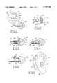
- FIG. 1illustrates an embodiment of the present invention which uses a sample chamber, a tubular member and an ear insert member;
- FIG. 2illustrates an alternate embodiment of an ear insert member for use with the present invention
- FIG. 3illustrates an alternate embodiment of the present invention which incorporates an additional transducer in the ear insert member
- FIG. 4illustrates an alternate embodiment which also uses an additional transducer in or adjacent to the ear insert member
- FIG. 5illustrates still another embodiment of the invention utilizing an additional transducer adjacent the ear insert member
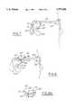
- FIG. 6illustrates use of the present invention with a behind-the-ear electronics module
- FIG. 7illustrates use of the present invention with an electronics module incorporated into the temple of a pair of eyeglasses
- FIGS. 8 and 8Aillustrate a quick-change adapter mechanism for use with the present invention
- FIG. 9depicts an alternate embodiment of an ear insert member
- FIG. 10depicts a cross-over network for use with the present invention.
- sampling chambersare used to produce the low frequency audio.
- the sampling chambershave a pair of cavities and acoustical pressure is provided through a tube connected to one or both of the cavities.
- acoustical pressureis provided through a tube connected to one or both of the cavities.
- the acoustic pressure at the open end of the tube of a chamber-tube configuration, for constant transducer input,will be nominally constant from sub-audio frequencies up to the chamber tube Helmholtz resonance frequency, where there will occur a peak. Above that frequency, typically 1-4 kHz for small earphone modules, the asymptotic response is a 6 db per octave rolloff in pressure (12 db in acoustic intensity). Superimposed on this asymptote are a series of resonant peaks whose frequencies are determined by the cavity-tube geometry. These resonances can be substantially reduced by using known acoustic compensation techniques.
- This compensationcould involve the use of a parallel tube, which is closed at the end, and acoustic damping elements. It is also possible to compensate the resonances by using complementary electrical filtering, e.g. with DSP (Digital Signal Processing). For high fidelity reproduction of the audio source it is necessary to compensate for the high frequency rolloff. This can be done electrically with an active filter or with DSP, using well known techniques.
- DSPDigital Signal Processing
- the sample chambersare combined with separate high frequency transducers in an audio system.
- the additional transducersprovide better high frequency audio performance where desired.
- the sample chamberstransfer the low frequency audio very well. However, above the cavity Helmholtz resonance, the pressure transfer falls at 6 dB per octave (12 dB for intensity).
- the resonant frequencyis typically on the order of 100-200 Hz or higher.
- a transducer or array of transducers in a sample chamber with the audio output being supplied through a tubular memberis sufficient to produce high quality sound.
- Various networks and circuit diagrams for combining the sample chamber and additional transducersare shown in U.S. patent application Ser. No. 482,759.
- the audio signalsare produced by a module having a sample chamber, as well as a tubular member which is positioned and stabilized in the ear canal with an ear insert member.
- a schematic diagram of such a systemis shown in FIG. 1.
- the sample chamber 10is incorporated into a module 12.
- a tubular member 14is attached to the sample chamber at one end 16 and attached to an ear insert member 20 at its other end 18.
- a small transducer 22is positioned in the chamber 10 which is divided into two cavities 24 and 26. Cavity 24 is sealed, except for a small leak to equalize atmospheric pressure changes.
- the second cavity 26is coupled to the outside by tubular member 14.
- the transducer 22is mounted on a common wall 28 separating the two cavities 24 and 26.
- the diaphragm of the transducerfunctions as a moving boundary between the two cavities.
- the volumes of the cavities 24 and 26are designed for minimum volume consistent with using a transducer with adequate volume displacement to produce the desired acoustic pressure within the cavities and consequently at the open end of the tube 14.
- the module 12also contains electronic circuitry 13, including amplifiers, equalizers and the like, as well as the power source, which preferably is a long life battery, which are standard in the art. Also, the module 12 could be formed as a behind-the-ear module 100, as shown in FIG. 6, or included as an electronics module 120 positioned on the end of the temple 122 of a pair of glasses 124, as shown in FIG. 7.
- the present inventionis adaptable for use either as a personal communication system for one ear of the wearer or as a stereo high fidelity system for both ears of the wearer.
- a behind-the-ear module or eyeglass temple moduleis situated adjacent both of the ears of the wearer.
- the two modulesare connected by appropriate wiring to a common control system.
- the control systemcould be positioned at another part of the wearer's body, such as at the waist or at the wrist.
- the end 18 of the tube 14 emerging from the open cavity 26is arranged so that its open end is positioned at or near the entrance to the ear canal of the wearer.
- the open end of the tubeis stabilized in position in the ear with ear insert member 20.
- the ear insert member 20can be molded to fit the individual wearer's ears, or can be an insert which is formable and usable for a wide variety of sizes and shapes of ear canals.
- the ear insert and support member 20is made from an acoustically transparent material, such as an open cell foam material.
- Acoustically transparent materialsare materials which allow essentially 100% transmission of sounds through them. In this manner, the wearer has the ability to hear sounds connected with his or her environment at the same time that audio from the personal communication system is being supplied through the tubular member 14.
- Foam materialsare available which have negligible acoustic loss up to several centimeters in thickness.
- the tubular member 14is secured to the foam insert 20 either directly, for example, with an adhesive, or by pressing the tube over or onto a fitting which has been secured into the foam piece.
- a fitting 30 of this typeis shown, for example, in FIG. 2.
- FIG. 9Another embodiment of ear insert member 150 is shown in FIG. 9.
- a molded or formed housing 152is attached to the end 18 of the tubular member 14.
- the circular housing 152has a socket 154 for insertion of the end of the tubular member, an annular groove 156 and a circular disc 158.
- the foam insert member 20has a central cavity 160, a first portion 162 which fits over groove 156 and a second portion 164 which fits over the disc 158.
- the foam insert member 20is releasably held in place on the housing 132 in this manner, and can be easily removed for replacement or the like by manipulation of the soft foam material.
- the housing 152can be made of any conventional plastic or metal material, such as Delrin or aluminum, but preferably is made from an acrylic material.
- the foam or other acoustically transparent material used for the ear insertis shaped to fit comfortably in the wearer's ear.
- the foam or other material forming the ear insert membercan be covered with a thin layer 32 of highly flexible plastic material. This is shown in FIG. 2. If a coating 32 is utilized, it is extensively perforated with openings 34 in order to maintain the overall acoustic transparency of the insert. In this regard, it may be preferable to only coat the areas of the insert which contact the ear of the wearer. This also makes it possible to maintain maximum malleability of the insert to conform comfortably to the wearer's ear. Further, full transparency of the insert can be maintained if there are not two opposed perforated walls which may cause attenuating resonances.
- an additional transducer 40is integrated into the tubular member and ear insert member. This is shown in FIG. 3. This embodiment provides better high frequency response. As explained above, even though low frequencies are transferred very well by the present invention, the cavity Helmholtz resonance may reduce the efficiency of the system at high frequencies.
- an additional transducer 40it preferably is made from a piezoelectric material.
- a satisfactory plastic piezo materialis PVDF, although other equivalent materials could be utilized.
- the transduceris preferably on the order of 25 microns in thickness, and approximately 0.5 cm in diameter.
- the transducer 40is preferably molded directly into the foam ear insert member or bonded to it. Also, the electrical wires or connectors 42 and 43 from the electronics module to the transducer are protected in this manner from contact with the wearer's skin.
- the piezoelectric transducer 40also is perforated with a plurality of small holes or openings 44 in order to maintain acoustical transparency of the entire ear insert member for external sounds. With appropriate perforations, the system loses less than one dB of acoustical loss over the entire audible spectrum.
- additional resonant compensating tubular members with acoustic damping resisterscan be added to the system. These are known in the art. Also, as indicated above, these additional components preferably, but not necessarily, are situated in appropriate housings, such as the modules 100 and 120 (shown in FIGS. 6 and 7).
- the piezoelectric material forming the additional transducer 50is wrapped around the end 18 of the tubular member 14.
- the transducer 50is preferably positioned in the ear insert member 20 or molded into it as desired.
- the open end of tube 14is positioned to maintain proximity to the entrance of the wearer's ear canal.
- Poweris supplied to the transducer 50 by appropriate wires or connectors 52 and 53. If voltage is supplied so as to squeeze the tubular member 14, as is known, for example, in inkjet printers, the tube 14 will shrink and expand in diameter and generate pressure within the tube. This can produce the desired high frequency audio for the system.
- the piezo materialcan be divided into annular sections or members 54 as shown in FIG. 5.
- the annular membersare secured or molded onto the end 18 of the tubular member 14 and connected by wires or connectors 56 to the electronics module.
- an effective acoustic peristaltic pumpis created. This also could be used to produce the requisite audio frequencies desired for the system.
- the two transducer systemis preferably driven from a cross-over network which directs the low frequencies to the chamber transducer and the high frequencies to the ear insert transducer.
- the relative drive levels of the two frequenciesare preferably set to achieve an overall subjectively uniform response.
- a cross-over network 180which can be used in accordance with the present invention is shown in FIG. 10.
- the audio signals Sare split by band pass fillers 181 and 182 into a first frequency band 184 which are the lower frequency signals, and a second frequency band 186 which are the higher frequency signals.
- the higher frequency signalsare amplified by amplifier 188 and used to drive the piezoelectric transducer (PET) 190.
- the lower frequency signalsare amplified by amplifier 192 and used to drive the transducer 22 in the sampler chamber 10.
- Tubular member 14is connected to the chamber 10.
- the fillers 181 and 182can have either an analog or digital implementation.
- the electronic components of the present systemcould be provided in a wide variety of shapes and sizes and positioned at a wide variety of positions on the wearer.
- the componentsare all integrated into an module 100 which fits behind the ear 80 of the wearer, as shown in FIG. 6, or into an eyeglass module 120, as shown in FIG. 7.
- the module 100contains the sample chamber 10 and the electronic components 13, such as the power supply, amplifiers, and the like.
- the tubular member 14is connected to the module 100 at one end and stabilized and positioned in the ear canal with ear insert member 20 at the other end.
- the ear of the weareris referred to by the reference numeral 80.
- the module 120is incorporated onto the ends of the temples 122 of a pair of eyeglasses 124 and preferably contains all of the electronics 13.
- the tubular member 14is connected at one end to the module 120 and positioned in proximity to the entrance of the ear canal of the wearer's ear 80 within ear insert member 20.
- the present inventionprovides improved systems for personal communication and entertainment devices and hearing aid devices which are lightweight, easily portable, wearable by the user, and provide high quality audio.
- the audio for the systemscould be provided by a number of various electronic devices and mechanisms known today. These include, but are not limited to, cellular and portable telephones, personal communications systems (PCS), AM and FM radios, cassette tape players, CD players, personal monitors and paging systems, and portable video systems.
- problemsare often encountered by wearers who want to utilize portable, wearable communication, entertainment and/or hearing aid systems incorporated in behind-the-ear modules, or as part of a pair of eyeglasses. Problems are encountered with behind-the-ear modules since they interfere with placement of the earpieces of eyeglasses. Also, if the module is incorporated into the temples of a pair of eyeglasses, then problems are encountered when the wearer wants to switch to a pair of sunglasses, reading glasses, etc. If the module is integrated into one pair of glasses, then the audio function of the system is removed every time the eyeglasses are taken off or the wearer must secure duplicates of possibly expensive electronics and acoustics modules. Also, this may require removing the ear insert at the same time, which may be awkward.
- the temple of the glasses and a behind-the-ear modulecould interfere and cause discomfort, or position the glasses such that vision is impaired or distorted.
- the problembecomes especially troublesome when the audio system is required or desired to be used for long periods of time and several changes of glasses or removal of the glasses for one reason or another are required.
- an adapter mechanism 60is utilized, as shown in FIGS. 8 and 8A.
- the adapter 60incorporates a first attachment member 62, a second attachment member 64, and mating connector members 66 and 68.
- the attachment member 62is secured to the tubular member 14 (or alternately to the module 100).
- the attachment member 64is attached to the end of the temple 122' of eyeglasses 124'.
- the temples 122'have been shortened by removal of the earpiece and a tubular member 70 is connected to the shortened end.
- the attachment member 64is attached to or integrated as part of the tubular connector 70.
- the connecting members 66 and 68are preferably made from Velcro-type connecting hook and loop members, but can be of any conventional releasable connector mechanisms known today. For example, a combination of a permanent magnet and a mating ferrous material could be utilized. With the quick change adapter mechanism 60, the eyeglasses 124' can be connected to the module 100 or tubular member 14 in a relatively quick and easy manner, simply by attaching and detaching the fasteners.
- the adapter member 62can be glued or otherwise affixed to the tubular member 14.
- a "peel-off" type of adhesivecould be used to secure the member 62 to the member 14.
- the module 100 and tubular member 14could be manufactured with adapter member 62 molded or otherwise integrated into its structure.
- the tubular adapter 70is provided to facilitate use of the adapter member 60 with various sizes and shapes of eyeglass frames.
- the temple 122'is cut off at an appropriate point and the tubing 70 slipped over the end, designed for a snug fit. If necessary, an adhesive may be supplied inside the tubing 70 to insure a permanent fitting.
- both temples of the pair of eyeglasseswould need to be modified.
- the connector materials forming the connector members 66 and 68should be selected to provide the best compromise between a solid, reliable connection and one which is easily disengaged without dislodging the behind-the-ear module 100.
Landscapes
- Physics & Mathematics (AREA)
- Health & Medical Sciences (AREA)
- Acoustics & Sound (AREA)
- Engineering & Computer Science (AREA)
- General Health & Medical Sciences (AREA)
- Otolaryngology (AREA)
- General Physics & Mathematics (AREA)
- Ophthalmology & Optometry (AREA)
- Optics & Photonics (AREA)
- Manufacturing & Machinery (AREA)
- Signal Processing (AREA)
- Headphones And Earphones (AREA)
Abstract
Description
Claims (10)
Priority Applications (1)
| Application Number | Priority Date | Filing Date | Title |
|---|---|---|---|
| US08/826,477US5737436A (en) | 1995-09-19 | 1997-03-27 | Earphones with eyeglass attatchments |
Applications Claiming Priority (2)
| Application Number | Priority Date | Filing Date | Title |
|---|---|---|---|
| US53076095A | 1995-09-19 | 1995-09-19 | |
| US08/826,477US5737436A (en) | 1995-09-19 | 1997-03-27 | Earphones with eyeglass attatchments |
Related Parent Applications (1)
| Application Number | Title | Priority Date | Filing Date |
|---|---|---|---|
| US53076095AContinuation | 1995-09-19 | 1995-09-19 |
Publications (1)
| Publication Number | Publication Date |
|---|---|
| US5737436Atrue US5737436A (en) | 1998-04-07 |
Family
ID=24114844
Family Applications (1)
| Application Number | Title | Priority Date | Filing Date |
|---|---|---|---|
| US08/826,477Expired - LifetimeUS5737436A (en) | 1995-09-19 | 1997-03-27 | Earphones with eyeglass attatchments |
Country Status (5)
| Country | Link |
|---|---|
| US (1) | US5737436A (en) |
| EP (1) | EP0852105A4 (en) |
| JP (1) | JP2002515197A (en) |
| AU (1) | AU7154196A (en) |
| WO (1) | WO1997011574A1 (en) |
Cited By (100)
| Publication number | Priority date | Publication date | Assignee | Title |
|---|---|---|---|---|
| US6021207A (en)* | 1997-04-03 | 2000-02-01 | Resound Corporation | Wireless open ear canal earpiece |
| WO2000005924A1 (en)* | 1998-07-22 | 2000-02-03 | Resound Corporation | Two-way communication earpiece |
| US6038329A (en)* | 1996-07-08 | 2000-03-14 | Lee; Youn M. | Earphone device |
| USD421755S (en)* | 1999-02-17 | 2000-03-21 | Unicon Incorporated | Telephone headset ear hook |
| WO2001042847A1 (en)* | 1999-12-09 | 2001-06-14 | C-Kesp Limited | Visual aid |
| FR2820936A1 (en)* | 2001-02-15 | 2002-08-16 | Michel Roger Emanuel | NEW CONCEPT OF HEARING DEVICES ON GLASSES WITH THEIR DIFFERENT ACCESSORIES MAKING THEIR WEAR AESTHETIC AND MORE COMFORTABLE |
| US6554097B2 (en)* | 2000-09-13 | 2003-04-29 | Koenig Florian Meinhard | Low-radiation headphone |
| US20030095679A1 (en)* | 1997-11-06 | 2003-05-22 | Tom Rickards | Industrial hearing protection and communication assembly |
| US6690807B1 (en)* | 1999-04-20 | 2004-02-10 | Erika Köchler | Hearing aid |
| US20040132509A1 (en)* | 2003-03-07 | 2004-07-08 | Cardo Systems Inc. | Wireless communication headset with exchangeable attachments |
| US20040157649A1 (en)* | 2002-07-26 | 2004-08-12 | James Jannard | Wireless interactive headset |
| US20040160573A1 (en)* | 2000-06-02 | 2004-08-19 | James Jannard | Wireless interactive headset |
| US20050078847A1 (en)* | 2002-01-07 | 2005-04-14 | Dobras David Q. | High comfort sound delivery system |
| US20050078274A1 (en)* | 2003-04-15 | 2005-04-14 | Ipventure, Inc. | Tethered electrical components for eyeglasses |
| US20050201585A1 (en)* | 2000-06-02 | 2005-09-15 | James Jannard | Wireless interactive headset |
| US20050230596A1 (en)* | 2004-04-15 | 2005-10-20 | Howell Thomas A | Radiation monitoring system |
| US20050274404A1 (en)* | 2004-06-15 | 2005-12-15 | Paul Bergman | Walking aid device |
| US20060003803A1 (en)* | 2003-04-15 | 2006-01-05 | Thomas C D | Eyeglasses for wireless communications |
| USD514613S1 (en) | 2004-12-02 | 2006-02-07 | Oakley, Inc. | Eyeglass and eyeglass components |
| US7013009B2 (en) | 2001-06-21 | 2006-03-14 | Oakley, Inc. | Eyeglasses with wireless communication features |
| EP1093700A4 (en)* | 1998-06-29 | 2006-04-26 | Resound Corp | High quality open-canal sound transduction device and method |
| USD523461S1 (en) | 1906-12-02 | 2006-06-20 | Oakley, Inc. | Eyeglass component |
| US20060215864A1 (en)* | 2005-03-16 | 2006-09-28 | Widex A/S | Earpiece for a hearing aid and a hearing aid |
| US20070009130A1 (en)* | 2001-08-10 | 2007-01-11 | Clear-Tone Hearing Aid | BTE/CIC auditory device and modular connector system therefor |
| US20070030442A1 (en)* | 2003-10-09 | 2007-02-08 | Howell Thomas A | Eyeglasses having a camera |
| US20070046889A1 (en)* | 2005-08-24 | 2007-03-01 | Miller Kenneth C | Eyewear with weighted flexible temples |
| USD538836S1 (en) | 2005-02-11 | 2007-03-20 | Oakley, Inc. | Eyewear module |
| US20070064969A1 (en)* | 2005-09-21 | 2007-03-22 | Chou Chia L | Glasses with an audio transceiver |
| US20070064966A1 (en)* | 2001-08-10 | 2007-03-22 | Hear-Wear Technologies, Llc | BTE/CIC auditory device and modular connector system therefor |
| US20070109491A1 (en)* | 2003-10-09 | 2007-05-17 | Howell Thomas A | Eyeglasses with a heart rate monitor |
| US20070116318A1 (en)* | 2000-01-10 | 2007-05-24 | Tom Rickards | Hearing protection and communication assembly |
| US20070121987A1 (en)* | 2005-11-29 | 2007-05-31 | Fielding Jerry Jr | Lanyard assembly for audio device |
| DE102005062577B3 (en)* | 2005-12-27 | 2007-07-05 | Siemens Audiologische Technik Gmbh | Hearing aid behind ear, has two parts and one of two parts of connecting mechanism is partly spherical and other part is partly spherical cage shaped, so that both parts can be rotated relative to each other in connecting state |
| US7255437B2 (en) | 2003-10-09 | 2007-08-14 | Howell Thomas A | Eyeglasses with activity monitoring |
| USD548767S1 (en) | 2005-08-22 | 2007-08-14 | Oakley, Inc. | Eyeglass and eyeglass components |
| EP1329084A4 (en)* | 2000-10-26 | 2007-10-10 | Orrin Klitzner | User interface for a portable communication device |
| EP1847868A1 (en) | 2006-04-19 | 2007-10-24 | Siemens Audiologische Technik GmbH | Behind the ear hearing device including a spectacles adapter with a thin acoustic tube |
| US20080068559A1 (en)* | 2006-09-20 | 2008-03-20 | Howell Thomas A | Eyeglasses with activity monitoring and acoustic dampening |
| US7380936B2 (en) | 2003-10-09 | 2008-06-03 | Ipventure, Inc. | Eyeglasses with a clock or other electrical component |
| US20080151179A1 (en)* | 2003-10-09 | 2008-06-26 | Howell Thomas A | Tethered electrical components for eyeglasses |
| US20080218684A1 (en)* | 2004-07-28 | 2008-09-11 | Howell Thomas A | Eyeglasses with RFID tags |
| US7461936B2 (en) | 2000-06-02 | 2008-12-09 | Oakley, Inc. | Eyeglasses with detachable adjustable electronics module |
| US20090059159A1 (en)* | 2004-04-15 | 2009-03-05 | Howell Thomas A | Eyewear with radiation detection system |
| US20090058611A1 (en)* | 2006-02-28 | 2009-03-05 | Takashi Kawamura | Wearable device |
| US7500747B2 (en) | 2003-10-09 | 2009-03-10 | Ipventure, Inc. | Eyeglasses with electrical components |
| US7581833B2 (en) | 2003-10-09 | 2009-09-01 | Ipventure, Inc. | Eyewear supporting after-market electrical components |
| US20090226022A1 (en)* | 2005-12-15 | 2009-09-10 | Petteri Vairio | Carrying Arrangement for Fastening a Headset for a Mobile Terminal at the User's Ear |
| EP2101512A1 (en) | 2008-03-12 | 2009-09-16 | AKG Acoustics GmbH | In-ear earphone with multiple transducers |
| US20100061579A1 (en)* | 2008-09-09 | 2010-03-11 | Rickards Thomas M | Communication eyewear assembly |
| US7760898B2 (en) | 2003-10-09 | 2010-07-20 | Ip Venture, Inc. | Eyeglasses with hearing enhanced and other audio signal-generating capabilities |
| US20100206925A1 (en)* | 2007-07-23 | 2010-08-19 | Fielding Jr Jerry | Lanyard assembly for audio device |
| US20100309426A1 (en)* | 2003-04-15 | 2010-12-09 | Howell Thomas A | Eyewear with multi-part temple for supporting one or more electrical components |
| US20110051981A1 (en)* | 2009-09-03 | 2011-03-03 | Akg Acoustics Gmbh | In-Ear Earphone |
| EP1980134A4 (en)* | 2006-01-30 | 2011-03-23 | Etymotic Res Inc | Insert earphone using a moving coil driver |
| US7922321B2 (en) | 2003-10-09 | 2011-04-12 | Ipventure, Inc. | Eyewear supporting after-market electrical components |
| US20110280425A1 (en)* | 2010-05-17 | 2011-11-17 | Gibbons Wayne M | Open Ear Fitting |
| US8109629B2 (en) | 2003-10-09 | 2012-02-07 | Ipventure, Inc. | Eyewear supporting electrical components and apparatus therefor |
| US20120189155A1 (en)* | 2011-01-26 | 2012-07-26 | TrackThings LLC | Apparatus for Electrically Coupling Contacts by Magnetic Forces |
| US20130077043A1 (en)* | 2011-09-23 | 2013-03-28 | Sean Thomas Moran | Modular Eye Wear System with Multi-Functional Interchangeable Accessories and Method for System Component Selection, Assembly and Use |
| ITTV20120033A1 (en)* | 2012-03-01 | 2013-09-02 | Trevi Coliseum S R L | FRAME FOR GLASSES |
| US8588448B1 (en) | 2008-09-09 | 2013-11-19 | Energy Telecom, Inc. | Communication eyewear assembly |
| US8744113B1 (en) | 2012-12-13 | 2014-06-03 | Energy Telecom, Inc. | Communication eyewear assembly with zone of safety capability |
| US8876285B2 (en) | 2006-12-14 | 2014-11-04 | Oakley, Inc. | Wearable high resolution audio visual interface |
| FR3005394A1 (en)* | 2013-05-13 | 2014-11-14 | Genevieve Baril | EARMUFFS. |
| JP5719057B1 (en)* | 2014-04-28 | 2015-05-13 | 幸重 足田 | Earphone cord holder |
| US9088848B2 (en) | 2005-12-13 | 2015-07-21 | Geelux Holdings, Ltd. | Biologically fit wearable electronics apparatus and methods |
| US20150245131A1 (en)* | 2014-02-21 | 2015-08-27 | Earlens Corporation | Contact hearing system with wearable communication apparatus |
| US20160057545A1 (en)* | 2014-08-21 | 2016-02-25 | National Chiao Tung University | Piezoelectric speaker driving system and method thereof |
| US9282393B2 (en) | 2004-07-06 | 2016-03-08 | Kaddan Entertainment, Inc. | System and method for securing headphone transducers |
| US9299348B2 (en) | 2011-01-26 | 2016-03-29 | TrackThings LLC | Method and apparatus for obtaining information from the web |
| US9402121B2 (en) | 2014-01-10 | 2016-07-26 | Geelux Holdings, Ltd. | Wearable electronic device |
| US9405135B2 (en) | 2011-09-15 | 2016-08-02 | Ipventure, Inc. | Shutter eyewear |
| CN105959851A (en)* | 2016-06-14 | 2016-09-21 | 常州市武进晶丰电子有限公司 | Ear type treble compensation headphone |
| US9606375B2 (en) | 2005-12-13 | 2017-03-28 | Geelux Holdings, Ltd. | Biologically fit wearable electronics apparatus |
| US9619201B2 (en) | 2000-06-02 | 2017-04-11 | Oakley, Inc. | Eyewear with detachable adjustable electronics module |
| EP1871141B2 (en)† | 2006-06-19 | 2017-04-19 | Sonion Nederland B.V. | Hearing aid having two receivers each amplifying a different frequency range |
| US9648407B2 (en) | 2014-06-12 | 2017-05-09 | Kaddan Entertainment, Inc. | System and method for managing headphone wires |
| US9720258B2 (en) | 2013-03-15 | 2017-08-01 | Oakley, Inc. | Electronic ornamentation for eyewear |
| US9720260B2 (en) | 2013-06-12 | 2017-08-01 | Oakley, Inc. | Modular heads-up display system |
| US9807493B1 (en) | 2016-04-21 | 2017-10-31 | Human, Incorporated | Attachment apparatus |
| US9864211B2 (en) | 2012-02-17 | 2018-01-09 | Oakley, Inc. | Systems and methods for removably coupling an electronic device to eyewear |
| EP2941224B1 (en) | 2013-01-02 | 2018-02-28 | The Children's Hospital of Philadelphia | Apparatus for correcting auricular deformities |
| US10042186B2 (en) | 2013-03-15 | 2018-08-07 | Ipventure, Inc. | Electronic eyewear and display |
| US10222617B2 (en) | 2004-12-22 | 2019-03-05 | Oakley, Inc. | Wearable electronically enabled interface system |
| US10310296B2 (en) | 2003-10-09 | 2019-06-04 | Ingeniospec, Llc | Eyewear with printed circuit board |
| US10345625B2 (en) | 2003-10-09 | 2019-07-09 | Ingeniospec, Llc | Eyewear with touch-sensitive input surface |
| US10624790B2 (en) | 2011-09-15 | 2020-04-21 | Ipventure, Inc. | Electronic eyewear therapy |
| USD894154S1 (en)* | 2016-10-18 | 2020-08-25 | Samson Technologies Corp. | Head-worn microphone |
| US10777048B2 (en) | 2018-04-12 | 2020-09-15 | Ipventure, Inc. | Methods and apparatus regarding electronic eyewear applicable for seniors |
| CN113267906A (en)* | 2021-06-22 | 2021-08-17 | 深圳添翼精密电子有限公司 | Changeable mirror leg of broadcast state and intelligent glasses |
| US11513371B2 (en) | 2003-10-09 | 2022-11-29 | Ingeniospec, Llc | Eyewear with printed circuit board supporting messages |
| US11592689B2 (en) | 2020-05-01 | 2023-02-28 | Ferris State University | Adaptor system for eyewear and cochlear implants |
| US11630331B2 (en) | 2003-10-09 | 2023-04-18 | Ingeniospec, Llc | Eyewear with touch-sensitive input surface |
| US11644693B2 (en) | 2004-07-28 | 2023-05-09 | Ingeniospec, Llc | Wearable audio system supporting enhanced hearing support |
| US11733549B2 (en) | 2005-10-11 | 2023-08-22 | Ingeniospec, Llc | Eyewear having removable temples that support electrical components |
| US11829518B1 (en) | 2004-07-28 | 2023-11-28 | Ingeniospec, Llc | Head-worn device with connection region |
| US11852901B2 (en) | 2004-10-12 | 2023-12-26 | Ingeniospec, Llc | Wireless headset supporting messages and hearing enhancement |
| US12044901B2 (en) | 2005-10-11 | 2024-07-23 | Ingeniospec, Llc | System for charging embedded battery in wireless head-worn personal electronic apparatus |
| US20240259725A1 (en)* | 2022-10-28 | 2024-08-01 | Shenzhen Shokz Co., Ltd. | Headphones |
| US12339521B2 (en) | 2020-10-27 | 2025-06-24 | Skullcandy, Inc. | Eyeglasses with associated true wireless earbuds |
Families Citing this family (4)
| Publication number | Priority date | Publication date | Assignee | Title |
|---|---|---|---|---|
| EP1810548B1 (en)* | 2005-05-24 | 2008-09-17 | Varibel B.V. | Connector assembly for connecting an earpiece of a hearing aid to a glasses temple |
| EP1727393A1 (en)* | 2005-05-24 | 2006-11-29 | Varibel B.V. | Connector assembly for connecting an earpiece of a hearing aid to a glasses temple |
| EP1971894B1 (en)* | 2006-01-06 | 2015-08-26 | Marcio Marc Abreu | Biologically fit wearable electronics apparatus and methods |
| FR2915049A1 (en)* | 2007-04-10 | 2008-10-17 | Richard Chene | ELEMENT FOR THE EARLY TRANSMISSION OF THE SOUND OF A SPEAKER AND EQUIPMENT PROVIDED WITH SUCH A ELEMENT |
Family Cites Families (8)
| Publication number | Priority date | Publication date | Assignee | Title |
|---|---|---|---|---|
| US3588384A (en)* | 1968-12-16 | 1971-06-28 | Electro Voice | Headset incorporating a microphone and an earphone |
| US3789164A (en)* | 1970-08-17 | 1974-01-29 | R Ryder | Earphone assembly |
| DE3627117A1 (en)* | 1986-08-06 | 1988-02-11 | Siemens Ag | HOEREREET WITH A HOUSING TO BE WEARED BEHIND THE EAR |
| CA1336295C (en)* | 1988-09-21 | 1995-07-11 | Masayoshi Miura | Sound reproducing apparatus |
| US5276740A (en)* | 1990-01-19 | 1994-01-04 | Sony Corporation | Earphone device |
| US5327178A (en)* | 1991-06-17 | 1994-07-05 | Mcmanigal Scott P | Stereo speakers mounted on head |
| US5412736A (en)* | 1992-03-23 | 1995-05-02 | Keliiliki; Shawn P. | Personal audio system and earphone for same |
| US5357585A (en)* | 1993-07-09 | 1994-10-18 | Khyber Technologies Corporation | Headphone assembly |
- 1996
- 1996-09-03AUAU71541/96Apatent/AU7154196A/ennot_activeAbandoned
- 1996-09-03JPJP51273097Apatent/JP2002515197A/enactivePending
- 1996-09-03WOPCT/US1996/014099patent/WO1997011574A1/ennot_activeApplication Discontinuation
- 1996-09-03EPEP96932951Apatent/EP0852105A4/ennot_activeWithdrawn
- 1997
- 1997-03-27USUS08/826,477patent/US5737436A/ennot_activeExpired - Lifetime
Cited By (229)
| Publication number | Priority date | Publication date | Assignee | Title |
|---|---|---|---|---|
| USD523461S1 (en) | 1906-12-02 | 2006-06-20 | Oakley, Inc. | Eyeglass component |
| US6038329A (en)* | 1996-07-08 | 2000-03-14 | Lee; Youn M. | Earphone device |
| US20050185815A1 (en)* | 1996-09-06 | 2005-08-25 | Tom Rickards | Hearing protection and communication assembly |
| US7133532B2 (en)* | 1996-09-06 | 2006-11-07 | Energy Telecom, Inc. | Hearing protection and communication assembly |
| US6021207A (en)* | 1997-04-03 | 2000-02-01 | Resound Corporation | Wireless open ear canal earpiece |
| US20030095679A1 (en)* | 1997-11-06 | 2003-05-22 | Tom Rickards | Industrial hearing protection and communication assembly |
| US6950531B2 (en)* | 1997-11-06 | 2005-09-27 | Energy Telecom, Inc. | Industrial hearing protection and communication assembly |
| EP1093700A4 (en)* | 1998-06-29 | 2006-04-26 | Resound Corp | High quality open-canal sound transduction device and method |
| US6681022B1 (en)* | 1998-07-22 | 2004-01-20 | Gn Resound North Amerca Corporation | Two-way communication earpiece |
| WO2000005924A1 (en)* | 1998-07-22 | 2000-02-03 | Resound Corporation | Two-way communication earpiece |
| USD421755S (en)* | 1999-02-17 | 2000-03-21 | Unicon Incorporated | Telephone headset ear hook |
| US6690807B1 (en)* | 1999-04-20 | 2004-02-10 | Erika Köchler | Hearing aid |
| WO2001042847A1 (en)* | 1999-12-09 | 2001-06-14 | C-Kesp Limited | Visual aid |
| US20070116318A1 (en)* | 2000-01-10 | 2007-05-24 | Tom Rickards | Hearing protection and communication assembly |
| US7682018B2 (en) | 2000-06-02 | 2010-03-23 | Oakley, Inc. | Eyeglasses with detachable adjustable electronics module |
| US20090086159A1 (en)* | 2000-06-02 | 2009-04-02 | Jannard James H | Eyeglasses with Detachable Adjustable Electronics Module |
| US7278734B2 (en) | 2000-06-02 | 2007-10-09 | Oakley, Inc. | Wireless interactive headset |
| US7988283B2 (en) | 2000-06-02 | 2011-08-02 | Oakley, Inc. | Eyeglasses with detachable adjustable electronics module |
| US9619201B2 (en) | 2000-06-02 | 2017-04-11 | Oakley, Inc. | Eyewear with detachable adjustable electronics module |
| US8020989B2 (en) | 2000-06-02 | 2011-09-20 | Oakley, Inc. | Wireless interactive headset |
| US20040160573A1 (en)* | 2000-06-02 | 2004-08-19 | James Jannard | Wireless interactive headset |
| US7150526B2 (en) | 2000-06-02 | 2006-12-19 | Oakley, Inc. | Wireless interactive headset |
| US20050201585A1 (en)* | 2000-06-02 | 2005-09-15 | James Jannard | Wireless interactive headset |
| US7461936B2 (en) | 2000-06-02 | 2008-12-09 | Oakley, Inc. | Eyeglasses with detachable adjustable electronics module |
| US6554097B2 (en)* | 2000-09-13 | 2003-04-29 | Koenig Florian Meinhard | Low-radiation headphone |
| EP1329084A4 (en)* | 2000-10-26 | 2007-10-10 | Orrin Klitzner | User interface for a portable communication device |
| WO2002065198A1 (en)* | 2001-02-15 | 2002-08-22 | Michel Emanuel | Novel design of hearing aids clipped on spectacles with their various accessories for aesthetic and more comfortable wear |
| FR2820936A1 (en)* | 2001-02-15 | 2002-08-16 | Michel Roger Emanuel | NEW CONCEPT OF HEARING DEVICES ON GLASSES WITH THEIR DIFFERENT ACCESSORIES MAKING THEIR WEAR AESTHETIC AND MORE COMFORTABLE |
| US8010156B2 (en) | 2001-06-21 | 2011-08-30 | Oakley, Inc. | Eyeglasses with electronic components |
| US8473004B2 (en) | 2001-06-21 | 2013-06-25 | Oakley, Inc. | Eyeglasses with electronic components |
| US7013009B2 (en) | 2001-06-21 | 2006-03-14 | Oakley, Inc. | Eyeglasses with wireless communication features |
| US7231038B2 (en) | 2001-06-21 | 2007-06-12 | Oakley, Inc. | Eyeglasses with wireless communication features |
| US8787970B2 (en) | 2001-06-21 | 2014-07-22 | Oakley, Inc. | Eyeglasses with electronic components |
| US20060183427A1 (en)* | 2001-06-21 | 2006-08-17 | Peter Warren | Eyeglasses with wireless communication features |
| US9451068B2 (en) | 2001-06-21 | 2016-09-20 | Oakley, Inc. | Eyeglasses with electronic components |
| US20100309427A1 (en)* | 2001-06-21 | 2010-12-09 | Oakley, Inc. | Eyeglasses with electronic components |
| US20100226520A1 (en)* | 2001-08-10 | 2010-09-09 | Hear-Wear Technologies, Llc | BTE/CIC Auditory Device and Modular Connector System Therefor |
| US9591393B2 (en) | 2001-08-10 | 2017-03-07 | Hear-Wear Technologies, Llc | BTE/CIC auditory device and modular connector system therefor |
| US20070009130A1 (en)* | 2001-08-10 | 2007-01-11 | Clear-Tone Hearing Aid | BTE/CIC auditory device and modular connector system therefor |
| US8976991B2 (en) | 2001-08-10 | 2015-03-10 | Hear-Wear Technologies, Llc | BTE/CIC auditory device and modular connector system therefor |
| US20090296969A1 (en)* | 2001-08-10 | 2009-12-03 | Hear-Wear Technologies, Llc | Bte/cic auditory device and modular connector system therefor |
| US8094850B2 (en) | 2001-08-10 | 2012-01-10 | Hear-Wear Technologies, Llc | BTE/CIC auditory device and modular connector system therefor |
| US7606382B2 (en) | 2001-08-10 | 2009-10-20 | Hear-Wear Technologies LLC | BTE/CIC auditory device and modular connector system therefor |
| US20070064966A1 (en)* | 2001-08-10 | 2007-03-22 | Hear-Wear Technologies, Llc | BTE/CIC auditory device and modular connector system therefor |
| US20070064967A1 (en)* | 2001-08-10 | 2007-03-22 | Hear-Wear Technologies, Llc | BTE/CIC auditory device and modular connector system therefor |
| US8050437B2 (en) | 2001-08-10 | 2011-11-01 | Hear-Wear Technologies, Llc | BTE/CIC auditory device and modular connector system therefor |
| US20050078847A1 (en)* | 2002-01-07 | 2005-04-14 | Dobras David Q. | High comfort sound delivery system |
| US7522743B2 (en)* | 2002-01-07 | 2009-04-21 | Step Communications | High comfort sound delivery system |
| US20050128431A1 (en)* | 2002-07-26 | 2005-06-16 | James Jannard | Multi-directional adjustment devices for speaker mounts for eyeglass with MP3 player |
| US7264350B2 (en) | 2002-07-26 | 2007-09-04 | Oakley, Inc. | Multi-directional adjustment devices for speaker mounts for eyeglass with MP3 player |
| US7213917B2 (en) | 2002-07-26 | 2007-05-08 | Oakley, Inc. | Electronically enabled eyewear |
| US20060146277A1 (en)* | 2002-07-26 | 2006-07-06 | James Jannard | Electronically enabled eyewear |
| US7445332B2 (en) | 2002-07-26 | 2008-11-04 | Oakley, Inc. | Wireless interactive headset |
| US7512414B2 (en) | 2002-07-26 | 2009-03-31 | Oakley, Inc. | Wireless interactive headset |
| US20050046790A1 (en)* | 2002-07-26 | 2005-03-03 | James Jannard | Speaker mounts for eyeglass with MP3 player |
| US7004582B2 (en) | 2002-07-26 | 2006-02-28 | Oakley, Inc. | Electronically enabled eyewear |
| US20050046789A1 (en)* | 2002-07-26 | 2005-03-03 | James Jannard | Actuator configuration for eyeglass with MP3 player |
| US20040160572A1 (en)* | 2002-07-26 | 2004-08-19 | James Jannard | Eyeglass with MP3 player |
| US7147324B2 (en) | 2002-07-26 | 2006-12-12 | Oakley, Inc. | Speaker mounts for eyeglass with MP3 player |
| US7216973B2 (en) | 2002-07-26 | 2007-05-15 | Oakley, Inc. | Eyeglass with MP3 player |
| US20040157649A1 (en)* | 2002-07-26 | 2004-08-12 | James Jannard | Wireless interactive headset |
| US20040160571A1 (en)* | 2002-07-26 | 2004-08-19 | James Jannard | Electronically enabled eyewear |
| US7409234B2 (en)* | 2003-03-07 | 2008-08-05 | Cardo Systems, Inc. | Wireless communication headset with exchangeable attachments |
| US20040132509A1 (en)* | 2003-03-07 | 2004-07-08 | Cardo Systems Inc. | Wireless communication headset with exchangeable attachments |
| US20100309426A1 (en)* | 2003-04-15 | 2010-12-09 | Howell Thomas A | Eyewear with multi-part temple for supporting one or more electrical components |
| US12078870B2 (en) | 2003-04-15 | 2024-09-03 | Ingeniospec, Llc | Eyewear housing for charging embedded battery in eyewear frame |
| US20060003803A1 (en)* | 2003-04-15 | 2006-01-05 | Thomas C D | Eyeglasses for wireless communications |
| US7792552B2 (en) | 2003-04-15 | 2010-09-07 | Ipventure, Inc. | Eyeglasses for wireless communications |
| US9690121B2 (en) | 2003-04-15 | 2017-06-27 | Ingeniospec, Llc | Eyewear supporting one or more electrical components |
| US7192136B2 (en) | 2003-04-15 | 2007-03-20 | Howell Thomas A | Tethered electrical components for eyeglasses |
| US20050078274A1 (en)* | 2003-04-15 | 2005-04-14 | Ipventure, Inc. | Tethered electrical components for eyeglasses |
| US8465151B2 (en) | 2003-04-15 | 2013-06-18 | Ipventure, Inc. | Eyewear with multi-part temple for supporting one or more electrical components |
| US7500747B2 (en) | 2003-10-09 | 2009-03-10 | Ipventure, Inc. | Eyeglasses with electrical components |
| US8905542B2 (en) | 2003-10-09 | 2014-12-09 | Ingeniospec, Llc | Eyewear supporting bone conducting speaker |
| US9547184B2 (en) | 2003-10-09 | 2017-01-17 | Ingeniospec, Llc | Eyewear supporting embedded electronic components |
| US10061144B2 (en) | 2003-10-09 | 2018-08-28 | Ingeniospec, Llc | Eyewear supporting embedded electronic components |
| US7481531B2 (en) | 2003-10-09 | 2009-01-27 | Ipventure, Inc. | Eyeglasses with user monitoring |
| US7438410B1 (en) | 2003-10-09 | 2008-10-21 | Ip Venture, Inc. | Tethered electrical components for eyeglasses |
| US10310296B2 (en) | 2003-10-09 | 2019-06-04 | Ingeniospec, Llc | Eyewear with printed circuit board |
| US7401918B2 (en) | 2003-10-09 | 2008-07-22 | Ipventure, Inc. | Eyeglasses with activity monitoring |
| US20090141233A1 (en)* | 2003-10-09 | 2009-06-04 | Howell Thomas A | Eyewear with monitoring capability |
| US12164180B2 (en) | 2003-10-09 | 2024-12-10 | Ingeniospec, Llc | Eyewear supporting distributed and embedded electronic components |
| US7581833B2 (en) | 2003-10-09 | 2009-09-01 | Ipventure, Inc. | Eyewear supporting after-market electrical components |
| US10330956B2 (en) | 2003-10-09 | 2019-06-25 | Ingeniospec, Llc | Eyewear supporting electrical components and apparatus therefor |
| US20080151179A1 (en)* | 2003-10-09 | 2008-06-26 | Howell Thomas A | Tethered electrical components for eyeglasses |
| US10345625B2 (en) | 2003-10-09 | 2019-07-09 | Ingeniospec, Llc | Eyewear with touch-sensitive input surface |
| US7380936B2 (en) | 2003-10-09 | 2008-06-03 | Ipventure, Inc. | Eyeglasses with a clock or other electrical component |
| US7621634B2 (en) | 2003-10-09 | 2009-11-24 | Ipventure, Inc. | Tethered electrical components for eyeglasses |
| US9033493B2 (en) | 2003-10-09 | 2015-05-19 | Ingeniospec, Llc | Eyewear supporting electrical components and apparatus therefor |
| US20070030442A1 (en)* | 2003-10-09 | 2007-02-08 | Howell Thomas A | Eyeglasses having a camera |
| US11086147B2 (en) | 2003-10-09 | 2021-08-10 | Ingeniospec, Llc | Eyewear supporting electrical components and apparatus therefor |
| US7677723B2 (en) | 2003-10-09 | 2010-03-16 | Ipventure, Inc. | Eyeglasses with a heart rate monitor |
| US11204512B2 (en) | 2003-10-09 | 2021-12-21 | Ingeniospec, Llc | Eyewear supporting embedded and tethered electronic components |
| US11243416B2 (en) | 2003-10-09 | 2022-02-08 | Ingeniospec, Llc | Eyewear supporting embedded electronic components |
| US7760898B2 (en) | 2003-10-09 | 2010-07-20 | Ip Venture, Inc. | Eyeglasses with hearing enhanced and other audio signal-generating capabilities |
| US7771046B2 (en) | 2003-10-09 | 2010-08-10 | I p Venture, Inc. | Eyewear with monitoring capability |
| US11513371B2 (en) | 2003-10-09 | 2022-11-29 | Ingeniospec, Llc | Eyewear with printed circuit board supporting messages |
| US20070279584A1 (en)* | 2003-10-09 | 2007-12-06 | Howell Thomas A | Eyeglasses with activity monitoring |
| US11536988B2 (en) | 2003-10-09 | 2022-12-27 | Ingeniospec, Llc | Eyewear supporting embedded electronic components for audio support |
| US7806525B2 (en) | 2003-10-09 | 2010-10-05 | Ipventure, Inc. | Eyeglasses having a camera |
| US8500271B2 (en) | 2003-10-09 | 2013-08-06 | Ipventure, Inc. | Eyewear supporting after-market electrical components |
| US11630331B2 (en) | 2003-10-09 | 2023-04-18 | Ingeniospec, Llc | Eyewear with touch-sensitive input surface |
| US8434863B2 (en) | 2003-10-09 | 2013-05-07 | Thomas A. Howell | Eyeglasses with a printed circuit board |
| US8430507B2 (en) | 2003-10-09 | 2013-04-30 | Thomas A. Howell | Eyewear with touch-sensitive input surface |
| US7922321B2 (en) | 2003-10-09 | 2011-04-12 | Ipventure, Inc. | Eyewear supporting after-market electrical components |
| US11762224B2 (en) | 2003-10-09 | 2023-09-19 | Ingeniospec, Llc | Eyewear having extended endpieces to support electrical components |
| US20110187990A1 (en)* | 2003-10-09 | 2011-08-04 | Howell Thomas A | Eyewear supporting after-market electrical components |
| US7255437B2 (en) | 2003-10-09 | 2007-08-14 | Howell Thomas A | Eyeglasses with activity monitoring |
| US11803069B2 (en) | 2003-10-09 | 2023-10-31 | Ingeniospec, Llc | Eyewear with connection region |
| US8109629B2 (en) | 2003-10-09 | 2012-02-07 | Ipventure, Inc. | Eyewear supporting electrical components and apparatus therefor |
| US20070109491A1 (en)* | 2003-10-09 | 2007-05-17 | Howell Thomas A | Eyeglasses with a heart rate monitor |
| US9488520B2 (en) | 2004-04-12 | 2016-11-08 | Ingeniospec, Llc | Eyewear with radiation detection system |
| US10060790B2 (en) | 2004-04-12 | 2018-08-28 | Ingeniospec, Llc | Eyewear with radiation detection system |
| US11644361B2 (en) | 2004-04-15 | 2023-05-09 | Ingeniospec, Llc | Eyewear with detection system |
| US10359311B2 (en) | 2004-04-15 | 2019-07-23 | Ingeniospec, Llc | Eyewear with radiation detection system |
| US20090059159A1 (en)* | 2004-04-15 | 2009-03-05 | Howell Thomas A | Eyewear with radiation detection system |
| US10539459B2 (en) | 2004-04-15 | 2020-01-21 | Ingeniospec, Llc | Eyewear with detection system |
| US20050230596A1 (en)* | 2004-04-15 | 2005-10-20 | Howell Thomas A | Radiation monitoring system |
| US11326941B2 (en) | 2004-04-15 | 2022-05-10 | Ingeniospec, Llc | Eyewear with detection system |
| US8770742B2 (en) | 2004-04-15 | 2014-07-08 | Ingeniospec, Llc | Eyewear with radiation detection system |
| US7500746B1 (en) | 2004-04-15 | 2009-03-10 | Ip Venture, Inc. | Eyewear with radiation detection system |
| US20050274404A1 (en)* | 2004-06-15 | 2005-12-15 | Paul Bergman | Walking aid device |
| US9282393B2 (en) | 2004-07-06 | 2016-03-08 | Kaddan Entertainment, Inc. | System and method for securing headphone transducers |
| US9510080B2 (en) | 2004-07-06 | 2016-11-29 | Kaddan Entertainment, Inc. | System and method for securing headphone transducers |
| US9820031B2 (en) | 2004-07-06 | 2017-11-14 | Kaddan Entertainment, Inc. | System and method for securing headphone transducers |
| US10200777B2 (en) | 2004-07-06 | 2019-02-05 | Kaddan Entertainment, Inc. | System and method for securing headphone transducers |
| US12025855B2 (en) | 2004-07-28 | 2024-07-02 | Ingeniospec, Llc | Wearable audio system supporting enhanced hearing support |
| US11829518B1 (en) | 2004-07-28 | 2023-11-28 | Ingeniospec, Llc | Head-worn device with connection region |
| US12238494B1 (en) | 2004-07-28 | 2025-02-25 | Ingeniospec, Llc | Head-worn device with connection region |
| US11921355B2 (en) | 2004-07-28 | 2024-03-05 | Ingeniospec, Llc | Head-worn personal audio apparatus supporting enhanced hearing support |
| US12140819B1 (en) | 2004-07-28 | 2024-11-12 | Ingeniospec, Llc | Head-worn personal audio apparatus supporting enhanced audio output |
| US8337013B2 (en) | 2004-07-28 | 2012-12-25 | Ipventure, Inc. | Eyeglasses with RFID tags or with a strap |
| US12001599B2 (en) | 2004-07-28 | 2024-06-04 | Ingeniospec, Llc | Head-worn device with connection region |
| US11644693B2 (en) | 2004-07-28 | 2023-05-09 | Ingeniospec, Llc | Wearable audio system supporting enhanced hearing support |
| US20080218684A1 (en)* | 2004-07-28 | 2008-09-11 | Howell Thomas A | Eyeglasses with RFID tags |
| US11852901B2 (en) | 2004-10-12 | 2023-12-26 | Ingeniospec, Llc | Wireless headset supporting messages and hearing enhancement |
| US12242138B1 (en) | 2004-10-12 | 2025-03-04 | Ingeniospec, Llc | Wireless headset supporting messages and hearing enhancement |
| USD514613S1 (en) | 2004-12-02 | 2006-02-07 | Oakley, Inc. | Eyeglass and eyeglass components |
| US10222617B2 (en) | 2004-12-22 | 2019-03-05 | Oakley, Inc. | Wearable electronically enabled interface system |
| US10120646B2 (en) | 2005-02-11 | 2018-11-06 | Oakley, Inc. | Eyewear with detachable adjustable electronics module |
| USD538836S1 (en) | 2005-02-11 | 2007-03-20 | Oakley, Inc. | Eyewear module |
| US20060215864A1 (en)* | 2005-03-16 | 2006-09-28 | Widex A/S | Earpiece for a hearing aid and a hearing aid |
| US7720244B2 (en)* | 2005-03-16 | 2010-05-18 | Widex A/S | Earpiece for a hearing aid and a hearing aid |
| USD548767S1 (en) | 2005-08-22 | 2007-08-14 | Oakley, Inc. | Eyeglass and eyeglass components |
| USD561816S1 (en) | 2005-08-22 | 2008-02-12 | Oakley, Inc. | Eyeglass component |
| US20070046889A1 (en)* | 2005-08-24 | 2007-03-01 | Miller Kenneth C | Eyewear with weighted flexible temples |
| US20070064969A1 (en)* | 2005-09-21 | 2007-03-22 | Chou Chia L | Glasses with an audio transceiver |
| US12248198B2 (en) | 2005-10-11 | 2025-03-11 | Ingeniospec, Llc | Eyewear having flexible printed circuit substrate supporting electrical components |
| US12044901B2 (en) | 2005-10-11 | 2024-07-23 | Ingeniospec, Llc | System for charging embedded battery in wireless head-worn personal electronic apparatus |
| US12313913B1 (en) | 2005-10-11 | 2025-05-27 | Ingeniospec, Llc | System for powering head-worn personal electronic apparatus |
| US11733549B2 (en) | 2005-10-11 | 2023-08-22 | Ingeniospec, Llc | Eyewear having removable temples that support electrical components |
| US12345955B2 (en) | 2005-10-11 | 2025-07-01 | Ingeniospec, Llc | Head-worn eyewear structure with internal fan |
| WO2007064684A3 (en)* | 2005-11-29 | 2007-11-22 | Jerry Fielding | Lanyard assembly for audio device |
| US7643646B2 (en) | 2005-11-29 | 2010-01-05 | Fielding Jr Jerry | Lanyard assembly for audio device |
| US20070121987A1 (en)* | 2005-11-29 | 2007-05-31 | Fielding Jerry Jr | Lanyard assembly for audio device |
| US10021474B2 (en) | 2005-12-13 | 2018-07-10 | Geelux Holdings, Ltd. | Biologically fit wearable electronics apparatus and methods |
| US10015577B2 (en) | 2005-12-13 | 2018-07-03 | Geelux Holdings, Ltd. | Biologically fit wearable electronics apparatus and methods |
| US10466510B2 (en) | 2005-12-13 | 2019-11-05 | Geelux Holdings, Ltd. | Biologically fit wearable electronics apparatus |
| US9088848B2 (en) | 2005-12-13 | 2015-07-21 | Geelux Holdings, Ltd. | Biologically fit wearable electronics apparatus and methods |
| US9723391B2 (en) | 2005-12-13 | 2017-08-01 | Geelux Holdings, Ltd. | Biologically fit wearable electronics apparatus and methods |
| US9122082B2 (en) | 2005-12-13 | 2015-09-01 | Geelux Holdings, Ltd. | Biologically fit wearable electronics apparatus and methods |
| US9606375B2 (en) | 2005-12-13 | 2017-03-28 | Geelux Holdings, Ltd. | Biologically fit wearable electronics apparatus |
| US20090226022A1 (en)* | 2005-12-15 | 2009-09-10 | Petteri Vairio | Carrying Arrangement for Fastening a Headset for a Mobile Terminal at the User's Ear |
| DE102005062577B3 (en)* | 2005-12-27 | 2007-07-05 | Siemens Audiologische Technik Gmbh | Hearing aid behind ear, has two parts and one of two parts of connecting mechanism is partly spherical and other part is partly spherical cage shaped, so that both parts can be rotated relative to each other in connecting state |
| EP1980134A4 (en)* | 2006-01-30 | 2011-03-23 | Etymotic Res Inc | Insert earphone using a moving coil driver |
| US20090058611A1 (en)* | 2006-02-28 | 2009-03-05 | Takashi Kawamura | Wearable device |
| US8581700B2 (en)* | 2006-02-28 | 2013-11-12 | Panasonic Corporation | Wearable device |
| US20070253586A1 (en)* | 2006-04-19 | 2007-11-01 | Siemens Audiologische Technik Gmbh | Behind-the-ear hearing device including eyeglass adapter with thin sound tube |
| EP1847868A1 (en) | 2006-04-19 | 2007-10-24 | Siemens Audiologische Technik GmbH | Behind the ear hearing device including a spectacles adapter with a thin acoustic tube |
| EP1871141B2 (en)† | 2006-06-19 | 2017-04-19 | Sonion Nederland B.V. | Hearing aid having two receivers each amplifying a different frequency range |
| US7543934B2 (en) | 2006-09-20 | 2009-06-09 | Ipventures, Inc. | Eyeglasses with activity monitoring and acoustic dampening |
| US20080068559A1 (en)* | 2006-09-20 | 2008-03-20 | Howell Thomas A | Eyeglasses with activity monitoring and acoustic dampening |
| US8876285B2 (en) | 2006-12-14 | 2014-11-04 | Oakley, Inc. | Wearable high resolution audio visual interface |
| US10288886B2 (en) | 2006-12-14 | 2019-05-14 | Oakley, Inc. | Wearable high resolution audio visual interface |
| US9494807B2 (en) | 2006-12-14 | 2016-11-15 | Oakley, Inc. | Wearable high resolution audio visual interface |
| US9720240B2 (en) | 2006-12-14 | 2017-08-01 | Oakley, Inc. | Wearable high resolution audio visual interface |
| US20100206925A1 (en)* | 2007-07-23 | 2010-08-19 | Fielding Jr Jerry | Lanyard assembly for audio device |
| US20090232341A1 (en)* | 2008-03-12 | 2009-09-17 | Bernhard Pinter | In-ear earphone |
| CN101534461B (en)* | 2008-03-12 | 2013-10-30 | Akg声学有限公司 | In-ear earphone with multiple transducers |
| US8311259B2 (en) | 2008-03-12 | 2012-11-13 | Akg Acoustics Gmbh | In-ear earphone |
| EP2101512A1 (en) | 2008-03-12 | 2009-09-16 | AKG Acoustics GmbH | In-ear earphone with multiple transducers |
| US8243973B2 (en) | 2008-09-09 | 2012-08-14 | Rickards Thomas M | Communication eyewear assembly |
| US8588448B1 (en) | 2008-09-09 | 2013-11-19 | Energy Telecom, Inc. | Communication eyewear assembly |
| US20100061579A1 (en)* | 2008-09-09 | 2010-03-11 | Rickards Thomas M | Communication eyewear assembly |
| US20110051981A1 (en)* | 2009-09-03 | 2011-03-03 | Akg Acoustics Gmbh | In-Ear Earphone |
| US8280094B2 (en) | 2009-09-03 | 2012-10-02 | Akg Acoustics Gmbh | In-ear earphone |
| US8462973B2 (en)* | 2010-05-17 | 2013-06-11 | W.L. Gore & Associates, Inc. | Ear fitting |
| US20110280425A1 (en)* | 2010-05-17 | 2011-11-17 | Gibbons Wayne M | Open Ear Fitting |
| US20120189155A1 (en)* | 2011-01-26 | 2012-07-26 | TrackThings LLC | Apparatus for Electrically Coupling Contacts by Magnetic Forces |
| US9299348B2 (en) | 2011-01-26 | 2016-03-29 | TrackThings LLC | Method and apparatus for obtaining information from the web |
| US9368884B2 (en)* | 2011-01-26 | 2016-06-14 | TrackThings LLC | Apparatus for electrically coupling contacts by magnetic forces |
| US9405135B2 (en) | 2011-09-15 | 2016-08-02 | Ipventure, Inc. | Shutter eyewear |
| US10624790B2 (en) | 2011-09-15 | 2020-04-21 | Ipventure, Inc. | Electronic eyewear therapy |
| US20130077043A1 (en)* | 2011-09-23 | 2013-03-28 | Sean Thomas Moran | Modular Eye Wear System with Multi-Functional Interchangeable Accessories and Method for System Component Selection, Assembly and Use |
| US9864211B2 (en) | 2012-02-17 | 2018-01-09 | Oakley, Inc. | Systems and methods for removably coupling an electronic device to eyewear |
| ITTV20120033A1 (en)* | 2012-03-01 | 2013-09-02 | Trevi Coliseum S R L | FRAME FOR GLASSES |
| US8744113B1 (en) | 2012-12-13 | 2014-06-03 | Energy Telecom, Inc. | Communication eyewear assembly with zone of safety capability |
| EP2941224B1 (en) | 2013-01-02 | 2018-02-28 | The Children's Hospital of Philadelphia | Apparatus for correcting auricular deformities |
| US11185446B2 (en) | 2013-01-02 | 2021-11-30 | The Children's Hospital Of Philadelphia | Method and apparatus for correcting auricular deformities |
| US10042186B2 (en) | 2013-03-15 | 2018-08-07 | Ipventure, Inc. | Electronic eyewear and display |
| US9720258B2 (en) | 2013-03-15 | 2017-08-01 | Oakley, Inc. | Electronic ornamentation for eyewear |
| US11042045B2 (en) | 2013-03-15 | 2021-06-22 | Ingeniospec, Llc | Electronic eyewear and display |
| FR3005394A1 (en)* | 2013-05-13 | 2014-11-14 | Genevieve Baril | EARMUFFS. |
| US9720260B2 (en) | 2013-06-12 | 2017-08-01 | Oakley, Inc. | Modular heads-up display system |
| US10288908B2 (en) | 2013-06-12 | 2019-05-14 | Oakley, Inc. | Modular heads-up display system |
| US9752724B2 (en) | 2014-01-10 | 2017-09-05 | Geelux Holdings, Ltd. | Wearable electronic device |
| US10132444B2 (en) | 2014-01-10 | 2018-11-20 | Geelux Holdings, Ltd. | Wearable electronic device |
| US10941900B2 (en) | 2014-01-10 | 2021-03-09 | Geelux Holdings, Ltd. | Wearable electronic device |
| US9402121B2 (en) | 2014-01-10 | 2016-07-26 | Geelux Holdings, Ltd. | Wearable electronic device |
| US20150245131A1 (en)* | 2014-02-21 | 2015-08-27 | Earlens Corporation | Contact hearing system with wearable communication apparatus |
| US9544675B2 (en)* | 2014-02-21 | 2017-01-10 | Earlens Corporation | Contact hearing system with wearable communication apparatus |
| US11070902B2 (en) | 2014-02-21 | 2021-07-20 | Earlens Corporation | Contact hearing system with wearable communication apparatus |
| US10003877B2 (en) | 2014-02-21 | 2018-06-19 | Earlens Corporation | Contact hearing system with wearable communication apparatus |
| JP5719057B1 (en)* | 2014-04-28 | 2015-05-13 | 幸重 足田 | Earphone cord holder |
| US9648407B2 (en) | 2014-06-12 | 2017-05-09 | Kaddan Entertainment, Inc. | System and method for managing headphone wires |
| US20160057545A1 (en)* | 2014-08-21 | 2016-02-25 | National Chiao Tung University | Piezoelectric speaker driving system and method thereof |
| US9723411B2 (en)* | 2014-08-21 | 2017-08-01 | National Chiao Tung University | Piezoelectric speaker driving system and method thereof |
| US10382855B2 (en) | 2016-04-21 | 2019-08-13 | Human, Incorporated | Attachment apparatus |
| US9807493B1 (en) | 2016-04-21 | 2017-10-31 | Human, Incorporated | Attachment apparatus |
| CN105959851B (en)* | 2016-06-14 | 2019-04-19 | 常州市武进晶丰电子有限公司 | In-Ear high pitch compensates earphone |
| CN105959851A (en)* | 2016-06-14 | 2016-09-21 | 常州市武进晶丰电子有限公司 | Ear type treble compensation headphone |
| USD894154S1 (en)* | 2016-10-18 | 2020-08-25 | Samson Technologies Corp. | Head-worn microphone |
| US10777048B2 (en) | 2018-04-12 | 2020-09-15 | Ipventure, Inc. | Methods and apparatus regarding electronic eyewear applicable for seniors |
| US11721183B2 (en) | 2018-04-12 | 2023-08-08 | Ingeniospec, Llc | Methods and apparatus regarding electronic eyewear applicable for seniors |
| US11592689B2 (en) | 2020-05-01 | 2023-02-28 | Ferris State University | Adaptor system for eyewear and cochlear implants |
| US12339521B2 (en) | 2020-10-27 | 2025-06-24 | Skullcandy, Inc. | Eyeglasses with associated true wireless earbuds |
| CN113267906A (en)* | 2021-06-22 | 2021-08-17 | 深圳添翼精密电子有限公司 | Changeable mirror leg of broadcast state and intelligent glasses |
| US12244996B2 (en)* | 2022-10-28 | 2025-03-04 | Shenzhen Shokz Co., Ltd. | Headphones |
| US20240259725A1 (en)* | 2022-10-28 | 2024-08-01 | Shenzhen Shokz Co., Ltd. | Headphones |
Also Published As
| Publication number | Publication date |
|---|---|
| EP0852105A4 (en) | 1999-11-17 |
| AU7154196A (en) | 1997-04-09 |
| EP0852105A1 (en) | 1998-07-08 |
| JP2002515197A (en) | 2002-05-21 |
| WO1997011574A1 (en) | 1997-03-27 |
Similar Documents
| Publication | Publication Date | Title |
|---|---|---|
| US5737436A (en) | Earphones with eyeglass attatchments | |
| US5694475A (en) | Acoustically transparent earphones | |
| US7310427B2 (en) | Recreational bone conduction audio device, system | |
| AU701453B2 (en) | Wearable audio system with enhanced performance | |
| KR101176827B1 (en) | Audio apparatus | |
| US6301367B1 (en) | Wearable audio system with acoustic modules | |
| JPS6113440B2 (en) | ||
| JP2004205839A (en) | Hearing aid | |
| US11523230B2 (en) | Earpiece with moving coil transducer and acoustic back volume | |
| AU706208B2 (en) | Sampled chamber transducer with enhanced low frequency response | |
| JPS6031350Y2 (en) | Sound collection and playback equipment system | |
| CN119404517A (en) | Hearing Devices | |
| HK1094749B (en) | Audio apparatus |
Legal Events
| Date | Code | Title | Description |
|---|---|---|---|
| STCF | Information on status: patent grant | Free format text:PATENTED CASE | |
| FPAY | Fee payment | Year of fee payment:4 | |
| FEPP | Fee payment procedure | Free format text:PAYOR NUMBER ASSIGNED (ORIGINAL EVENT CODE: ASPN); ENTITY STATUS OF PATENT OWNER: LARGE ENTITY | |
| AS | Assignment | Owner name:VULCAN PATENTS LLC, WASHINGTON Free format text:ASSIGNMENT OF ASSIGNORS INTEREST;ASSIGNOR:INTERVAL RESEARCH CORPORATION;REEL/FRAME:016353/0606 Effective date:20041229 | |
| FPAY | Fee payment | Year of fee payment:8 | |
| FPAY | Fee payment | Year of fee payment:12 | |
| FEPP | Fee payment procedure | Free format text:PAYER NUMBER DE-ASSIGNED (ORIGINAL EVENT CODE: RMPN); ENTITY STATUS OF PATENT OWNER: LARGE ENTITY Free format text:PAYOR NUMBER ASSIGNED (ORIGINAL EVENT CODE: ASPN); ENTITY STATUS OF PATENT OWNER: LARGE ENTITY | |
| AS | Assignment | Owner name:INTERVAL LICENSING LLC,WASHINGTON Free format text:MERGER;ASSIGNOR:VULCAN PATENTS LLC;REEL/FRAME:024160/0182 Effective date:20091223 Owner name:INTERVAL LICENSING LLC, WASHINGTON Free format text:MERGER;ASSIGNOR:VULCAN PATENTS LLC;REEL/FRAME:024160/0182 Effective date:20091223 | |
| AS | Assignment | Owner name:INTERVAL RESEARCH CORPORATION,CALIFORNIA Free format text:ASSIGNMENT OF ASSIGNORS INTEREST;ASSIGNOR:BOYDEN, JAMES H.;REEL/FRAME:024244/0616 Effective date:19950912 | |
| AS | Assignment | Owner name:VINTELL APPLICATIONS NY, LLC, DELAWARE Free format text:ASSIGNMENT OF ASSIGNORS INTEREST;ASSIGNOR:INTERVAL LICENSING, LLC;REEL/FRAME:024927/0865 Effective date:20100416 | |
| AS | Assignment | Owner name:CALLAHAN CELLULAR L.L.C., DELAWARE Free format text:MERGER;ASSIGNOR:VINTELL APPLICATIONS NY, LLC;REEL/FRAME:037540/0811 Effective date:20150826 |