US5737320A - Methods of communication for expandable telecommunication system - Google Patents
Methods of communication for expandable telecommunication systemDownload PDFInfo
- Publication number
- US5737320A US5737320AUS08/454,411US45441195DUS5737320AUS 5737320 AUS5737320 AUS 5737320AUS 45441195 DUS45441195 DUS 45441195DUS 5737320 AUS5737320 AUS 5737320A
- Authority
- US
- United States
- Prior art keywords
- packet
- node
- switched data
- information
- payload
- Prior art date
- Legal status (The legal status is an assumption and is not a legal conclusion. Google has not performed a legal analysis and makes no representation as to the accuracy of the status listed.)
- Expired - Lifetime
Links
- 238000000034methodMethods0.000titleclaimsabstractdescription129
- 230000006854communicationEffects0.000titledescription24
- 238000004891communicationMethods0.000titledescription24
- 230000015654memoryEffects0.000claimsdescription80
- 238000012546transferMethods0.000claimsdescription33
- 230000005540biological transmissionEffects0.000claimsdescription8
- 230000008569processEffects0.000abstractdescription53
- 238000012423maintenanceMethods0.000abstractdescription11
- 238000012545processingMethods0.000description33
- 238000010586diagramMethods0.000description18
- 238000013459approachMethods0.000description12
- 230000006870functionEffects0.000description12
- 238000006243chemical reactionMethods0.000description6
- 230000009977dual effectEffects0.000description6
- 230000004044responseEffects0.000description6
- 230000000694effectsEffects0.000description5
- 238000010276constructionMethods0.000description4
- 238000009432framingMethods0.000description4
- 230000008901benefitEffects0.000description3
- 230000000903blocking effectEffects0.000description3
- 238000001514detection methodMethods0.000description3
- RGNPBRKPHBKNKX-UHFFFAOYSA-NhexaflumuronChemical compoundC1=C(Cl)C(OC(F)(F)C(F)F)=C(Cl)C=C1NC(=O)NC(=O)C1=C(F)C=CC=C1FRGNPBRKPHBKNKX-UHFFFAOYSA-N0.000description3
- 230000008859changeEffects0.000description2
- 238000013461designMethods0.000description2
- 239000000284extractSubstances0.000description2
- 230000002452interceptive effectEffects0.000description2
- 238000002955isolationMethods0.000description2
- 238000012986modificationMethods0.000description2
- 230000004048modificationEffects0.000description2
- 238000013519translationMethods0.000description2
- 230000002411adverseEffects0.000description1
- 230000007175bidirectional communicationEffects0.000description1
- 230000002301combined effectEffects0.000description1
- 230000006835compressionEffects0.000description1
- 238000007906compressionMethods0.000description1
- 238000012937correctionMethods0.000description1
- 230000007812deficiencyEffects0.000description1
- 230000000593degrading effectEffects0.000description1
- 238000005516engineering processMethods0.000description1
- 230000007257malfunctionEffects0.000description1
- 230000002093peripheral effectEffects0.000description1
- 238000009877renderingMethods0.000description1
- 238000005070samplingMethods0.000description1
- 230000011664signalingEffects0.000description1
Images


Classifications
- H—ELECTRICITY
- H04—ELECTRIC COMMUNICATION TECHNIQUE
- H04L—TRANSMISSION OF DIGITAL INFORMATION, e.g. TELEGRAPHIC COMMUNICATION
- H04L49/00—Packet switching elements
- H04L49/10—Packet switching elements characterised by the switching fabric construction
- H04L49/104—Asynchronous transfer mode [ATM] switching fabrics
- H04L49/105—ATM switching elements
- H—ELECTRICITY
- H04—ELECTRIC COMMUNICATION TECHNIQUE
- H04L—TRANSMISSION OF DIGITAL INFORMATION, e.g. TELEGRAPHIC COMMUNICATION
- H04L12/00—Data switching networks
- H04L12/28—Data switching networks characterised by path configuration, e.g. LAN [Local Area Networks] or WAN [Wide Area Networks]
- H04L12/42—Loop networks
- H04L12/427—Loop networks with decentralised control
- H04L12/43—Loop networks with decentralised control with synchronous transmission, e.g. time division multiplex [TDM], slotted rings
- H—ELECTRICITY
- H04—ELECTRIC COMMUNICATION TECHNIQUE
- H04L—TRANSMISSION OF DIGITAL INFORMATION, e.g. TELEGRAPHIC COMMUNICATION
- H04L12/00—Data switching networks
- H04L12/64—Hybrid switching systems
- H04L12/6418—Hybrid transport
- H—ELECTRICITY
- H04—ELECTRIC COMMUNICATION TECHNIQUE
- H04Q—SELECTING
- H04Q11/00—Selecting arrangements for multiplex systems
- H04Q11/04—Selecting arrangements for multiplex systems for time-division multiplexing
- H04Q11/0428—Integrated services digital network, i.e. systems for transmission of different types of digitised signals, e.g. speech, data, telecentral, television signals
- H04Q11/0478—Provisions for broadband connections
- H—ELECTRICITY
- H04—ELECTRIC COMMUNICATION TECHNIQUE
- H04Q—SELECTING
- H04Q3/00—Selecting arrangements
- H04Q3/0016—Arrangements providing connection between exchanges
- H04Q3/002—Details
- H—ELECTRICITY
- H04—ELECTRIC COMMUNICATION TECHNIQUE
- H04L—TRANSMISSION OF DIGITAL INFORMATION, e.g. TELEGRAPHIC COMMUNICATION
- H04L12/00—Data switching networks
- H04L12/54—Store-and-forward switching systems
- H04L12/56—Packet switching systems
- H04L12/5601—Transfer mode dependent, e.g. ATM
- H04L2012/5603—Access techniques
- H04L2012/5609—Topology
- H04L2012/5612—Ring
- H—ELECTRICITY
- H04—ELECTRIC COMMUNICATION TECHNIQUE
- H04L—TRANSMISSION OF DIGITAL INFORMATION, e.g. TELEGRAPHIC COMMUNICATION
- H04L12/00—Data switching networks
- H04L12/64—Hybrid switching systems
- H04L12/6418—Hybrid transport
- H04L2012/6432—Topology
- H04L2012/6437—Ring
- H—ELECTRICITY
- H04—ELECTRIC COMMUNICATION TECHNIQUE
- H04L—TRANSMISSION OF DIGITAL INFORMATION, e.g. TELEGRAPHIC COMMUNICATION
- H04L12/00—Data switching networks
- H04L12/64—Hybrid switching systems
- H04L12/6418—Hybrid transport
- H04L2012/6443—Network Node Interface, e.g. Routing, Path finding
- H—ELECTRICITY
- H04—ELECTRIC COMMUNICATION TECHNIQUE
- H04L—TRANSMISSION OF DIGITAL INFORMATION, e.g. TELEGRAPHIC COMMUNICATION
- H04L12/00—Data switching networks
- H04L12/64—Hybrid switching systems
- H04L12/6418—Hybrid transport
- H04L2012/6445—Admission control
- H04L2012/6459—Multiplexing, e.g. TDMA, CDMA
- H—ELECTRICITY
- H04—ELECTRIC COMMUNICATION TECHNIQUE
- H04L—TRANSMISSION OF DIGITAL INFORMATION, e.g. TELEGRAPHIC COMMUNICATION
- H04L12/00—Data switching networks
- H04L12/64—Hybrid switching systems
- H04L12/6418—Hybrid transport
- H04L2012/6475—N-ISDN, Public Switched Telephone Network [PSTN]
- H—ELECTRICITY
- H04—ELECTRIC COMMUNICATION TECHNIQUE
- H04L—TRANSMISSION OF DIGITAL INFORMATION, e.g. TELEGRAPHIC COMMUNICATION
- H04L12/00—Data switching networks
- H04L12/64—Hybrid switching systems
- H04L12/6418—Hybrid transport
- H04L2012/6481—Speech, voice
- H—ELECTRICITY
- H04—ELECTRIC COMMUNICATION TECHNIQUE
- H04L—TRANSMISSION OF DIGITAL INFORMATION, e.g. TELEGRAPHIC COMMUNICATION
- H04L12/00—Data switching networks
- H04L12/64—Hybrid switching systems
- H04L12/6418—Hybrid transport
- H04L2012/6486—Signalling Protocols
- Y—GENERAL TAGGING OF NEW TECHNOLOGICAL DEVELOPMENTS; GENERAL TAGGING OF CROSS-SECTIONAL TECHNOLOGIES SPANNING OVER SEVERAL SECTIONS OF THE IPC; TECHNICAL SUBJECTS COVERED BY FORMER USPC CROSS-REFERENCE ART COLLECTIONS [XRACs] AND DIGESTS
- Y10—TECHNICAL SUBJECTS COVERED BY FORMER USPC
- Y10S—TECHNICAL SUBJECTS COVERED BY FORMER USPC CROSS-REFERENCE ART COLLECTIONS [XRACs] AND DIGESTS
- Y10S379/00—Telephonic communications
- Y10S379/909—Alternatives
Definitions
- the present inventionrelates generally to the field of telecommunications and, more specifically, to an architecture for connecting a plurality of programmable telecommunications switches to provide an expandable switching system and direct access for diverse communications applications.
- Switching capacitymust be analyzed in terms of current demand and projected demand in order to find a solution that is cost effective for both present and future service. For example, assume that a developing country is in the process of building a basic telecommunications system and intends to provide service to most of its current population. Such a population is most likely geographically distributed among small areas of high density (cities) and larger areas of low density (suburban and rural). In addition, the population is probably growing, but at different rates in different areas. Thus, the challenge for a telecommunications system designer is to provide sufficient switching capacity to support satisfactory service to most or all of the population while also anticipating likely increases in future demand and providing for economical expansion.
- PCNpersonal communications network
- bus extensionIn many conventional telecommunications switches, one or more internal buses are provided for carrying information, including voice, data and control information, between various parts of the switch. Buses are well suited for carrying such information since, by definition, multiple devices (e.g., circuit boards or cards) may interface with the buses and share them in accordance with a defined communication protocol. In a telecommunications switch, it is typical to find one or more buses interconnecting a series of cards which physically terminate telephone lines or trunks with other cards which perform switching, control or other functions.
- the concept underlying the bus extension approachis simply to connect additional cards, which provide additional switching capacity or other functions, with the existing buses.
- additional cardswhich provide additional switching capacity or other functions
- bus structures found in many, if not most, conventional switching systemsare generally designed solely for carrying out basic call processing and switching functions and do not provide ready, direct access to the ports for integrating new features and services.
- bus structuresare typically incapable of carrying packet switched data or other types of information.
- a second approachmay be referred to as the "modular" approach for shorthand.
- the conceptis to provide a switching system which is constructed from a series of essentially identical modules. Each module provides a finite amount of switching capacity which may be added to an existing system (one or more at a time) to increase the overall capacity of the system.
- each and every module as builtmust have the capability to receive circuit switched data from every other module up to whatever the maximum number of modules may be.
- itis the maximum switching capacity of the fully expanded system which determines the size of the memory that each module must have. For larger systems (i.e., on the order of a few thousand ports or larger), constructing such a memory becomes impractical due to both the accompanying number of physical network/line interfaces as well as the additional circuitry needed to control the memory.
- the modular approachis oriented toward performing basic switching operations and does not generally offer direct access to all the ports nor the capability of handling packet switched data or other types of information.
- the present inventionprovides an open, high speed, high bandwidth digital communication network for connecting multiple programmable telecommunications switches to form a large capacity, non-blocking switching system.
- the networkis implemented using one or more rings which provide a medium for transferring information over the network, and a plurality of programmable switches, each of which appears as a node on the network and serves a group of ports. Additional switches (nodes) may be added to the network as desired to increase the system's switching capacity.
- Each nodeincludes circuitry for transmitting and receiving variable-length, packetized information over the network, thus enabling each node to receive information from or transmit information to all other nodes.
- the networkmay carry any type of information present in the system including voice, data, video, multimedia, control, configuration and maintenance, and the bandwidth of the network may be divided or shared across various information types.
- devices or resources other than programmable switchesmay also act as nodes on the network, thereby gaining direct access to all information passing through the network.
- voice processing resourcessuch as voice mail/message systems or other enhanced services platforms may, by becoming nodes, gain direct access to all ports served by the system without the need for a large central switch.
- the present invention's ability to transfer information of any type, in a readily usable form, at high speed across the networkenables any service, feature or voice processing resource which is available at a given node to be provided to any port of the same or any other node.
- the present inventionalso provides methods and packet structures for communicating information over the network.
- different packet structuresare provided for communicating circuit switched information, voice processing information, data or maintenance information.
- all packetscontain a control portion or header, which typically includes address, status and other control information, and a payload portion for carrying data.
- ATMasynchronous transfer mode
- each nodeuses the network to transmit one or more packets, each of which has an "empty" payload, which are received first by an adjacent node.
- the adjacent nodedetermines the source of the received packet and the packet's status by the information contained in the control portion of the packet. If that adjacent node has information to send to the node which transmitted the packet, the adjacent node inserts such information into the payload of the packet, then allows the packet to pass to the next adjacent node on the network. If the adjacent node has no information for the node that originated the packet, the packet simply passes to the next adjacent node on the network.
- This processis repeated at each node until the packet traverses the complete network and returns with a "full" payload to the node from which it originated. At that point, information which was inserted into the packet by other nodes is captured by the node which originated the packet. In turn, each node transmits an "empty" packet which traverses the network and returns with information from other nodes. In this fashion, information of any type originating from any port served by any node may be transferred to any other port of the same or different node in the system.
- each nodeuses the network to transmit one or more packets, each of which has a "full" payload that contains information originating from that node.
- Each such packetis initially received by an adjacent node which determines the origin of the packet and whether any of the information contained therein is needed by that adjacent node. If so, such information is captured from the payload before the packet passes to the next adjacent node. If no information is needed, the packet simply passes to the next adjacent node. Again, this process is repeated until each node on the network has transmitted one or more packets with a "full" payload and each such packet has traversed the complete network, thereby allowing each node access to the information originated by each other node.
- each node to transfer information over the networkmay be advantageously established independently from the other nodes. Further, a given node need only contain a memory which is sufficiently large to accommodate that node's switching (or voice processing) capacity and not the entire capacity of the system.
- a second ringis used to connect all of the nodes, thereby providing a second network.
- the second networkeffectively doubles the maximum switching capacity of the system and also provides fault isolation in the event of a failure of the first network or one of the nodes.
- one or more additional networksare added to the nodes, further increasing the maximum switching capacity of the system and providing redundancy.
- one or more nodesmay be used to "bridge" one network to another.
- a bridge nodeis common to two networks and is capable of exchanging information bidirectionally between such networks.
- a bridge nodemay also be used to connect networks which operate at different speeds.
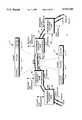
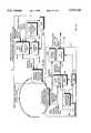
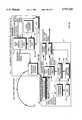
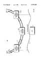
- FIGS. 1A and 1Bare a block diagram of an expandable telecommunications system which employs a ring-type inter-nodal network to transfer information between programmable switching nodes, all of which is constructed in accordance with a preferred embodiment of the present invention
- FIGS. 1C and 1Dare a block diagram of another embodiment of the present invention which employs a two-ring inter-nodal network to transfer information between programmable switching nodes;
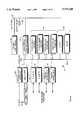
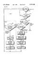
- FIG. 1Eshows various types of packets which may be used to transfer information over the networks of FIGS. 1A through 1D;
- FIG. 2Ais a block diagram of a one type of programmable switching node that may be used in the systems of FIGS. 1A through 1D;
- FIGS. 2B and 2Care a block diagram of a second type of programmable switching node that may be used in the systems of FIGS. 1A through 1D;
- FIGS. 3A, 3B, 3C, 3D and 3Eare a block diagram of the nodal switch shown in FIGS. 2A through 2C are;
- FIG. 3Fis a detailed diagram of the transmitter and receiver memories shown in FIGS. 3B and 3C;
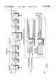
- FIG. 4Ais a block diagram which shows the receiving and transmitting functions involved in one method of transferring information over the inter-nodal networks of FIGS. 1A through 1D;
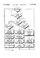
- FIG. 4Bis a flowchart showing the detailed steps of transferring circuit switched information in accordance with the method depicted in FIG. 4A;
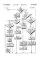
- FIGS. 4C and 4Dare a flowchart showing the detailed steps of transferring both circuit switched data and packet switched data in accordance with the method depicted in FIG. 4A;
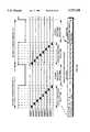
- FIG. 4Eis a timing diagram showing the time relationships between nodes for transferring both circuit switched data and packet switched data
- FIG. 5Ais a block diagram which depicts a second method of transferring information over the inter-nodal networks of FIGS. 1A through 1D;
- FIGS. 5B and 5Care a flowchart which depicts the detailed steps of transferring both circuit switched data and packet switched data in accordance with the method depicted in FIG. 5A;
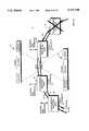
- FIGS. 6A and 6Bare a block diagram of an expandable telecommunications system which shows how communication may be maintained in event of a failure of one of the programmable switching nodes or a portion of the inter-nodal network;
- FIG. 7is a block diagram of another embodiment of the present invention which employs two two-ring inter-nodal networks, one for redundancy, to transfer information between programmable switching nodes;
- FIGS. 8A and 8Bare a block diagram of another embodiment of the present invention which employs an inter-nodal network to transfer information between one or more programmable switching nodes and one or more voice processing resources nodes;
- FIG. 8Cis a block diagram of one of the voice processing resource nodes shown in FIGS. 8A and 8B;
- FIGS. 9A and 9Bare a block diagram of another embodiment of the present invention which employs a programmable switching node as a bridge between two inter-nodal networks;
- FIG. 9Cis a block diagram of the bridge node shown in FIGS. 9A and 9B;
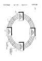
- FIG. 10Ais a block diagram of another embodiment of the present invention which employs eight rings to transfer information between programmable switching nodes, demonstrating the further expandability of the switching system;
- FIGS. 10B and 10Care a block diagram of one of the switching nodes of FIG. 10A.
- FIGS. 1A and 1Bshow a large capacity, expandable, fully programmable telecommunications switching system 2.
- the system 2includes a host 4 and a series of programmable switching nodes 6a-6h.
- Each of nodes 6a-6hincludes a host interface which is connected in communicating relationship with host 4 by a local area network (LAN) such as Ethernet or by multiple asynchronous communication (RS-232) links 8.
- LANlocal area network
- RS-232asynchronous communication
- LAN 8to provide host/node communications permits multiple hosts to control the system 2 (or parts thereof) by configuring each host as a "client” and each node as a "server.”
- clientthe host interfaces of nodes 6a and 6f-6h are truncated.
- Each of nodes 6a-6hincludes digital network/line interfaces for connection with the public switched telephone network (PSTN) or a private network 10.
- PSTNpublic switched telephone network
- private networkis intended in a broad sense to refer to any network or line or other interface other than the PSTN.
- the network/line interfaces of nodes 6b-6eare truncated.
- the network/line interfacesmay terminate either digital networks or analog trunks/lines, or combinations of both types.
- the network/line interfaces of a given nodemay include suitable interfaces for performing communications using ATM, Signalling System 7 (SS7), ISDN, T1/robbed bit, E1/CAS or other communication protocols.
- Node 6gis nominally designated “master node A” (active master node) and node 6h is nominally designated “master node B" (standby master node for redundancy).
- a synchronization reference line(ref 1 . . . ref n) extends from active master node 6g to each other switching node, although some such lines are truncated for clarity.
- any of nodes 6a-6hmay be configured as the active master node or the standby master node. However, at any given time, there may be one and only one active master node.
- Inter-nodal network 12which provides for high speed, high bandwidth digital communications between the nodes.
- inter-nodal network 12may be implemented using a ring which enables each of nodes 6a-6h to exchange packetized information with each other node served by network 12.
- Inter-nodal network 12may also be implemented with any of a variety of other types of communications networks, including Ethernet or other types of LANs, wireless communications networks and the PSTN (ATM/SONET). Using the PSTN for inter-nodal network 12 permits the nodes to be geographically distributed over large areas.
- a general packet structure 14 for exchanging information over the inter-nodal network 12consists of a control portion 16, a payload portion 18 and a status and control portion 19. Details of various packet structures for transferring different types of information are described below in connection with FIG. 1E.
- inter-nodal network 12Using inter-nodal network 12, a port of any given node may be connected to any other port of the same node or any other node in a fully non-blocking manner.
- each of nodes 6a-6hoperates independently with respect to the network/line interfaces terminated thereon. That is, any node may be removed or added to inter-nodal network 12 without impairing the operations or network/line interfaces of the other nodes. Further, the switching capacity of each switching node may be established independently from the switching capacities of other nodes (i.e., "small” switches may be combined with “large” switches on the same inter-nodal network 12). Thus, the overall switching capacity of the system 2 may be increased simply by adding additional switching nodes to the inter-nodal network 12, subject to certain limitations regarding the data transmission rate of that network, or additional inter-nodal networks 12 which are discussed below.
- system 2The overall operation of system 2 is controlled by host 4, which is commonly implemented with a personal computer (PC), workstation, fault tolerant or other computer on which a user's application software runs.
- Host 4 and each of nodes 6a-6hexchange messages over LAN/RS-232 links 8. Such messages are typically used to configure the nodes as well as direct call processing functions such as making connections and providing communications services (i.e., tone detection, tone generation and conferencing).
- FIGS. 1C and 1Dshow an expandable telecommunications switching system 17 which is similar to system 2 of FIGS. 1A and 1B, except that two rings are used to form the inter-nodal network 12 which connects nodes 6a-6h. PSTN/private network 10 is omitted for clarity.
- each of the two ringsmay be considered a separate inter-nodal network (or, alternatively, may be considered separate channels within a single network) since information may be transferred between nodes using either ring independently from the other, thereby effectively doubling the maximum switching capacity as compared to that of system 2.
- use of two ringsprovides fault isolation for the system 17. That is, should one ring fail (which would render the entire, single ring system 2 inoperable), the second ring may continue to transfer information between nodes, thereby keeping the system 17 at least partially operational.
- FIG. 1Eshows preferred embodiments for several packets which may be used to transfer information over inter-nodal network 12.
- a circuit switched data packet 3 and a voice processing packet 5are similarly constructed and each includes a control portion which contains a busy indicator (BI) followed by address and control information.
- the busy indicatormay be used, as described in detail below, to denote the current status of a given packet as either "busy" (meaning the packet may not be used by a node to transfer information) or "free".
- the address informationpreferably includes an address for either the source (SRC) node from which the packet originates or the destination (DEST) node for which the packet is intended, or both.
- Each address (source or destination)preferably includes a "network address" which uniquely identifies a particular inter-nodal network. Such identification is necessary since, as described below, multiple inter-nodal networks may be used to connect the same or different groups of nodes.
- Each address (source or destination)preferably also includes a "nodal address" which uniquely identifies a particular node on a particular inter-nodal network. Additional address information may include an explicit "port address" for uniquely identifying a particular port or groups of ports.
- packets 3 and 5which carry circuit switched data, require "port addresses” since such data is subject to distribution across multiple nodes and/or ports.
- implicit "port addresses”may be determined by maintaining a predetermined order of the circuit switched data within the payload.
- packets 3 and 5are depicted as having sufficient payload capacities to carry a total of 2,048 bytes of circuit switched data. When such bytes are placed in the payload, they are preferably arranged in an order which corresponds exactly with the sequence of time slots at a given node.
- any given nodemay either load circuit switched data into or extract data from the payload and, by simply counting the position of a particular byte relative to the first byte in the payload, know exactly the time slot with which the byte corresponds.
- packets 7 and 9do not generally require "port addresses" since the information carried by those types of packets is not circuit switched data.
- control portion 16may include additional information to specify the packet type, the length of the packet, a packet sequence number or other information.
- each packet typemay be varied depending upon which node transmits a given packet.
- the payload capacities of packets 3 and 5may be different so long as they provide sufficient capacity to carry circuit switched data up to the maximum number of ports switched or processed by a given node.
- a particular nodeis capable of switching or processing a maximum of 2,048 ports
- that nodepreferably transmits packets 3 and 5 with payloads having capacity for up to 2,048 bytes of circuit switched data.
- a different nodeis capable of switching only 512 ports, that node preferably transmits packets 3 and 5 with payloads having capacity for up to 512 bytes of circuit switched data.
- the payload portions of all packet typesare preferably followed by status and control information, which may include a checksum or other information for error detection and correction.
- a packet switched data packet 7 and a maintenance packet 9are similarly constructed (their lengths or payload capacities are variable), except that these types of packets do not carry circuit switched data but, as described below, are intended to transfer packet switched data which originates from a single point (source) and is destined to be transferred to another single point (destination) or to multiple single points ("broadcast").
- the status and control portions of packets 7 and 9may include information which indicates whether a destination node for a given packet was able to accept the packet or was busy at the time of receipt and unable to accept the packet.
- FIG. 2Ashows the major functional components of a preferred embodiment of one type of programmable switching node which may be used in the systems of FIGS. 1A through 1D.
- Digital or analog network/line interfacesare terminated on a series of line card input/output (IO) cards 20.
- IOinput/output
- network/line interfaces representing a total of 2,048 portsmay be terminated by line card IO cards 20.
- a redundant line card IO card 22 and redundant IO bus 24may optionally be provided to permit continued operation of the switching node in the event of a failure of one of line card IO cards 20.
- a series of digital network T1, E1, J1 or analog trunk/line line cards 26communicate with line card IO cards 20 over line card (LC) IO lines 28.
- Line cards 26are also interfaced with redundant switching buses 30a and 30b.
- an optional redundant line card 32may be provided, which communicates with redundant line card IO card 22 over redundant LC IO lines 34.
- Other types of network/line interfacessuch as DS3, SONET or others may also be provided.
- MFDSPmultifunction digital signal processing
- a particular nodemay operate independently from other nodes in terms of performing diverse communications services.
- only one node(or a subset of all of the nodes) may be equipped with cards 36 or 38, and inter-nodal network 12 may be used to provide communications services to other nodes which are not so equipped.
- a ring (network) IO card 40aserves as an interface between one pair of rings (designated Set A, Rings 1 and 2), which together are designated inter-nodal network 12a, and a nodal switch 44a that is designated the "local bus master," the significance of which is described below.
- a first host interface 42ahandles all communication between host 4 and the node of FIG. 2A.
- a second, redundant ring (network) IO card 40bserves as an interface between a redundant pair of rings (designated Set B, Rings 3 and 4) which together form a second inter-nodal network 12b, and a redundant nodal switch 44b, which is preferably of the same construction as nodal switch 44a.
- a second host interface 42bprovides a communication link with host 4.
- a link 46provides for communication between nodal switches 44a and 44b. Link 46 is used only to connect a nodal switch which is operating as the local bus master with another nodal switch which is operating as a redundant local bus master.
- line cards 26perform real time call processing functions which are required by network/line interfaces, including analog to digital conversion, if necessary.
- Line cards 26transmit and receive time division multiplex (TDM) circuit switched data over switching buses 30a and 30b.
- TDMtime division multiplex
- Each of nodal switches 44a and 44b, MFDSP cards 36 and ISDN-24 cards 38receive, over the buses 30a and 30b, circuit switched data transmitted in all time slots from all line cards 26.
- Each of nodal switches 44a and 44b, MFDSP cards 36 and ISDN-24 cards 38has the ability, under the direction of the local bus master (i.e., nodal switch 44a), to transmit circuit switched data to the line cards 26, over buses 30a and 30b, during predetermined time slots.
- switching buses 30a and 30beach include a high level data link control (HDLC) bus over which CPUs in nodal switches 44a and 44b, MFDSP cards 36 and ISDN-24 cards 38 exchange control messages.
- HDLChigh level data link control
- the term "local port”shall be used to refer, with respect to a given node, to a time slot containing circuit switched data transmitted from a line card 26 to all nodal switches 44, MFDSP cards 36 and ISDN-24 cards 38 (if any), or a time slot containing data transmitted from any nodal switch 44, MFDSP card 36 or ISDN-24 card 38 to a line card 26.
- the term “remote port”shall be used to refer, with respect to a given node, to a local port of a different node.
- each node 6a-6his capable of time switching up to 2,048 local ports.
- each of nodal switches 44a and 44bincludes a time switch capable of switching 2,048 time slots.
- the switching memory of each nodal switch 44a and 44bneed only be sufficiently large to accommodate the maximum number of local ports and not the switching capacity of the entire system. A significant advantage of this aspect of the present invention may be appreciated by momentarily referring again to FIGS. 1A and 1B.
- a preferred embodiment of the system 2is capable of switching a total of 16,384 ports.
- the switch (nodal switch 44a) within each of nodes 6a-6hneed only contain a switching memory which is large enough to switch 2,048 local ports, not 16,384 ports of the entire system 2.
- FIGS. 2B and 2Cshow a preferred embodiment of a second type of programmable switching node.
- This type of nodeis preferably based on an off-the-shelf PC which includes a PC-486 (or equivalent) and peripherals 48, an ISA (AT) bus 50 and a mass storage device 52.
- the PC-486 48may be used to run a user's application software and effectively operate as a host 4.
- an optional host interface 42amay be used to connect an "external" host (such as host 4 in FIGS. 1A through 1D) to control the node.
- an "external" hostsuch as host 4 in FIGS. 1A through 1D
- several additional componentsare provided in this embodiment.
- a voice processing resources bus interface 54provides bidirectional communication between switching bus 30a and two voice processing buses, PEB bus 60 and/or MVIP bus 62.
- PEB bus 60 and MVIP bus 62represent well known, "standard" interfaces for communicating with commercially available, widely used voice processing resources 56 and 58, respectively.
- voice processing resources 56 and 58For example, Dialogic Corporation of New Jersey produces a family of voice processing resource boards or cards which plug directly into PEB bus 60 and may be used in diverse applications including voice mail, fax mail, interactive voice response and others.
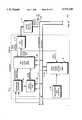
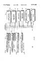
- FIGS. 3A through 3EThe detailed construction of a preferred embodiment of nodal switch 44a is shown in FIGS. 3A through 3E.
- a central processing unit (CPU) with associated RAM/ROM 64is connected in communicating relationship with a CPU address bus 114 and a CPU data bus 116.
- CPU 64is also connected in communicating relationship with an HDLC bus (part of switching buses 30a and 30b) and may, depending upon the configuration of nodal switch 44a discussed below, also be connected in communicating relationship with host 4.
- HDLC buspart of switching buses 30a and 30b
- a data transmitter 66is connected in communicating relationship with CPU address and data buses 114 and 116 and two packet handling circuits 78a and 78b. Transmitter 66 is also connected to receive circuit switched data for local ports over switching bus 30a (redundant switching bus 30b is omitted for clarity). As explained below, depending upon its mode of operation, transmitter 66 may receive and time switch circuit switched data which is flowing in a direction from a Line card to a Switch (LSDATA) or, alternatively, may receive and time switch data which is flowing in a direction from a Switch to a Line card (SLDATA). Transmitter 66 includes two ring maps 96, 98, corresponding to rings 1 and 2, respectively, a local sequential counter/map 100 and a quad-port local transmitter memory 102.
- LSDATALine card to a Switch
- SLDATASwitch to a Line card
- a data receiver 68is connected in communicating relationship with CPU data and address buses 114 and 116, and with a space switch control circuit 112 whose output is transmitted over switching bus 30a. Receiver 68 may, in conjunction with space switch control circuit 112, depending upon its mode of operation, output circuit switched data which flows in either the SLDATA or LSDATA direction (e.g., whichever is opposite to that of the data input to transmitter 66). Receiver 68 includes a sequential count/map 104, a local time slot map 106, a tri-port local receiver memory 108, a pad lookup memory 110, a dual-port local data packet receiver memory 118 and a sequential map/control 120.
- a high speed data receiver 70ais physically interfaced with ring 1 for receiving information in packet form from that ring.
- Receiver 70ais preferably implemented with a Hewlett-Packard Company HDMP-1014 receiver chip, which is an emitter coupled logic (ECL) device.
- Conversion circuit 72ais connected to receive the output signals of receiver 70a and produce output signals that are compatible with transistor-transistor logic (TTL).
- TTLtransistor-transistor logic
- the output of conversion circuit 72ais applied to a multiplexer 74a, which converts 16 bit data received from receiver 70a to 32 bit format.
- the output of multiplexer 74ais applied to a first-in-first-out (FIFO) memory 76a, a packet control circuit 92a and a ring select circuit 94.
- FIFOfirst-in-first-out
- a transmit flag (XF) circuit 90ais connected to packet control circuit 92a.
- the output of FIFO 76ais connected to packet handling circuit 78a.
- a demultiplexer circuit 80a, conversion circuit 82a and high speed data transmitter 84aperform functions which are the complements of multiplexer 74a, conversion circuit 72a and data receiver 70a, respectively.
- Transmitter 84ais preferably implemented with a Hewlett-Packard Company HDMP-1012 transmitter chip.
- circuitryfor interfacing with and transferring information to or from ring 2.
- Like reference numbersare used to identify corresponding components.
- the output of transmitter 84bis effectively connected to the input of receiver 70a, as indicated in phantom and reference number 71a.
- the input of receiver 70bis effectively connected to the output of transmitter 84a, as indicated by reference number 71b.
- Nodal switch 44aincludes additional components for timing and synchronization functions, which are grouped together as master node options 65 and local bus master options 71.
- Master node options 65include an inter-nodal synchronization circuit 67 and a master ring oscillator 69.
- Synchronization circuit 67generates reference signals ref 1 . . . ref n, each of which is supplied to one other switching node (see FIGS. 1A through 1D).
- Synchronization circuit 67also generates a nodal frame synchronization signal and a master ring clock signal, both of which are supplied to the packet control circuits 92a and 92b.
- Local bus master options 71include a local bus HDLC control 73 and a local synchronization circuit 75.
- Local bus HDLC control 73is connected in communicating relationship with CPU address and data buses 114 and 116, respectively, and generates a series of control signals 1 . . . . n which are supplied to all other cards (i.e., other nodal switches, line cards, MFDSP cards and ISDN-24 cards) associated with a given node for controlling access to the HDLC bus.
- Local synchronization circuit 75receives two input signals.
- One input signalis either one of the ref 1 . . . ref n signals (if another nodal switch is configured as the master node) or a loop timing source (if the nodal switch of FIGS. 3A through 3D is itself configured as the master node).
- the frame synchronization signal to circuit 75is obtained from either inter-nodal network (ring) 12 or one of ref 1 . . . ref n signals (if another nodal switch is configured as the master node). Circuit 75 will self-generate the frame synchronization signal if it is itself configured as the master node.
- Receive memory 108 and transmitter memory 102are shown in FIG. 3F.
- Transmitter memory 102is organized into dual circuit switched data banks 122 and 126, and dual constant areas 124 and 128.
- receiver memory 108is organized into dual circuit switched data banks 130 and 134, and dual constant areas 132 and 136.
- the dual circuit switched data banks of each memoryare operable, in conjunction with their respective maps and counters, to time switch circuit switched data.
- circuit switched data stored in the other circuit switched data bankis read "selectively."
- selectiveis used in this description to refer a process of applying addresses which are supplied by a map. During alternate 125 ⁇ s time periods, the roles of the circuit switched data banks reverse, thus interchanging the time slots to effect time switching.
- the constant areas of each memoryare generally available for storage of packet switched data by CPU 64, although the CPU 64 may access any location in either memory.
- each switchmay be configured to operate and what its responsibilities are in terms of system synchronization and initialization.
- each programmable switching node 6a-6hmust contain at least one, but may contain more than one, nodal switch 44a.
- two types of synchronizationmust be considered: inter-nodal network synchronization and PSTN (or private network) synchronization.
- Each nodal switch 44ais preferably configurable, by software, to operate as (1) a combination master node and local bus master, (2) a local bus master only, or (3) neither a master node nor a local bus master, but simply a "standard" switch.
- the configuration rulesare as follows. For each inter-nodal network 12, there must at any given time be one and only nodal switch which is operating as the master node. Whichever nodal switch is operating as the master node may also operate as the local bus master for its node. Within a given node, there must at any given time be one and only one nodal switch which is operating as the local bus master for that node. Lastly, within a given node, at any given time there may be one or more nodal switches operating as standard switches.
- a nodal switch operating as the master nodeThe responsibilities of a nodal switch operating as the master node are: (1) interface to PSTN for loop timing source (via circuit 75) for bit synchronization to digital networks of the PSTN; (2) generate system wide maintenance packets which all other nodes use for frame synchronization to digital networks of PSTN (based upon the nodal frame synchronization signal generated by circuit 67); (3) generate a switching reference clocking source (ref 1 . . . ref n) for bit synchronization of all non-master nodes; (4) optionally transmit a master framing signal over ref 1 . . . ref n; (5) generate a master clock for the inter-nodal network (master ring clock); (6) break the network (ring) clocking; and (7) keep the integrity of the inter-nodal network intact.
- a nodal switch operating as a local bus masterare: (1) interface to PSTN loop timing source or ref 1 . . . ref n from master node for bit synchronization to digital networks of the PSTN; (2) accept system wide maintenance packets generated by the master node for frame synchronization to digital networks of the PSTN; (3) communicate with the host; (4) communicate with all other cards in the node (other nodal switches, line cards, MFDSP cards and ISDN-24 cards) over the HDLC bus (controlled by controls signals 1 . . . n from HDLC control 73); and (5) generate nodal clock and flaming for all other cards in the node (local bus dock and local bus frame synchronization signals from circuit 75).
- a nodal switch operating as a standard switchaccept local bus clock and local bus frame synchronization signals from local bus master.
- the master nodeis responsible for initializing and configuring the system, which involves verifying the integrity and operability of the inter-nodal network 12 and, optionally, either assigning a nodal address to each node or polling the nodes to determine their previously assigned addresses. Once a node's address is assigned or determined, the master node may interrogate that node (i.e., using maintenance packets over inter-nodal network 12) to obtain configuration information such as nodal type, types of PSTN interfaces and/or protocols, switching capacity or other information. The master node may also have responsibilities for performing maintenance and administration functions. In addition, if multiple rings are used to implement any inter-nodal network, the master node may assign each nodal switch a particular ring for transmitting and receiving packets.
- the LSDATA(or SLDATA) which is input to transmitter memory 102 represents bytes of circuit switched data for local ports served by a given node. These bytes are written sequentially into the circuit switched data banks 122 and 126. Accordingly, the capacities of those data banks effectively determine the maximum number time slots which can be time switched by nodal switch 44a. For purposes of this overview, it is assumed that each data bank has a capacity of 2,048 bytes, meaning that a maximum of 2,048 local ports can be time switched by transmitter memory 102.
- transmitter 66 and packet handling circuit 78aformulate a packet whose payload is "empty" (meaning that the payload contains no circuit switched data, except for data from local ports which are connected to other local ports), but which has sufficient capacity to hold up to 2,048 bytes of circuit switched data.
- Transmitter 84athen transmits the "empty" packet.
- node 6dwill be the first node to receive that packet (i.e., the first adjacent node in the direction of flow around the ring is the first to receive the "empty" packet).
- Packet handling circuit 78areceives circuit switched data which is read selectively from circuit switched data banks 122 and 126 in response to addresses supplied by map (ring 1) 96.
- map (ring 1) 96addresses supplied by map (ring 1) 96.
- ring map 96causes particular bytes (or possibly all of the bytes or none of the bytes) of "local" circuit switched data stored in banks 122 and 126 to be selectively read from those banks and passed to the packet handling circuit 78a.
- map (ring 2) 98, memory 102 and packet handling circuit 78bA similar process occurs in parallel with map (ring 2) 98, memory 102 and packet handling circuit 78b.
- Packet handling circuit 78ainserts the "local" circuit switched data it receives (if any) into the payload of the received "empty" packet while that packet is passing to the transmitter 84a for transmission to the next node on the inter-nodal network 12. This process is repeated such that each other node, in succession, has the opportunity to insert its own “local” circuit switched data in the payload of the packet which originated from node 6c. If a particular node has no "local” circuit switched data to insert in the payload, the received packet passes unaltered to the next node. Eventually, the packet which was sent out “empty” traverses the entire ring on which it was transmitted and returns "full” to the node from which it was transmitted (originated).
- circuit switched data from the payload of the "full" packetis passed through ring select circuit 94, written sequentially into receiver memory 108 and then time switched out as LSDATA or SLDATA.
- This methodis referred to as the "Empty Send/Full Return” or ESFR method for shorthand.
- the ESFR methodis repeated such that each node, in turn, transmits an "empty" packet and receives a "full" return packet (on the node's assigned ring), thereby enabling "local" circuit switched data originating from any port at any node to be effectively transferred to any other port of the same or different node. All circuit switched data is preferably transferred in less than 125 ⁇ s to avoid loss of samples. As explained below, it should also be understood that the ESFR method may be used to "broadcast” or transfer information originating from one port to more than one other port.
- the conceptis for each node, in turn, to originate (transmit) a packet whose payload is "full" when sent, but "empty" upon return.
- a shorthand name for this methodis the "Full Send/Empty Return” or FSER method.
- FSER methodall of the "local" circuit switched data stored in circuit switched data banks 122 and 126 of transmitter memory 102 is read sequentially and supplied to packet handling circuit 78a.
- a "full" packetis constructed whose payload includes all of the "local” circuit switched data for a given node.
- the "full" packetis transmitted by transmitter 84a and is received by the first adjacent node.
- the data in the payloadis selectively extracted and passed, via ring select circuit 94, to receiver 68. That data is then selectively written into data banks 130 and 134 of receiver memory 108. This process is repeated until a "full" packet transmitted by each node has been received by every other node, thus achieving the same overall result of enabling "local" circuit switched data originating from any port at any node to be effectively transferred to any other port of the same or different node.
- inter-nodal network 12may also be used to transfer packet switched data.
- packet switched dataare data or maintenance information needed to control the switching system itself, X.25 packets, LAPB or LAPD packets.
- Packet switched dataappears at the output of ring select circuit 94, but is written into packet receiver memory 118, as opposed to memory 108. Once stored in memory 118, packet switched data is accessible by CPU 64 via CPU data bus 116.
- FIGS. 3A through 3E, 4A and 4Bfurther details of the ESFR method will be described. It should be understood that the flowchart of FIG. 4B represents the steps which are performed, in parallel, at each node by that node's packet control circuits (92a and 92b), the packet handling circuits 78a and 78b and related circuitry. If should be kept in mind that when the ESFR method is used, "empty" packets are transmitted on only one ring and received on only one ring (assigned during initialization). For this example, it is assumed that node 6i in FIG. 4A is preparing to transmit an "empty" packet over the inter-nodal network 12 for the purpose of collecting circuit switched data from other nodes, including node 6j.
- the processbegins at start on reset step 138, which is a state in which the node is essentially waiting for a frame (which contains a packet) to arrive on the inter-nodal network 12.
- a determinationis made whether the start of a frame has been detected. If a start of frame is not detected, the process returns to start 138. Alternatively, if the start of a frame is detected, meaning that a packet was received by node 6i, then the contents of the control portion of the packet are checked to determine if the packet is "busy” at step 142. A packet's "busy” or not busy (“free") status is indicated by the busy indicator (BI) in the control portion of the packet (FIG. 1E).
- BIbusy indicator
- step 144a determination is made whether the circuit switched data (CSD) window for node 6i is open.
- the "CSD window”refers to a designated period of time which is allocated for all of the nodes to transmit "empty" circuit switched data packets.
- step 148node 6i must insert "local connect data" (if any) into the payload of the "empty" packet while transmission continues.
- local connect datarefers to circuit switched data which is both originating from and destined for one or more local ports of a given node which is sending an "empty" packet.
- local connect datais circuit switched data which is to be switched from one local port to another local port of the same node over inter-nodal network 12.
- the transmit flag (XF) 90a(FIG. 3A) is set to serve as a reminder to node 6i that it has transmitted an "empty" packet over the network 12 and that it should receive the return "full" packet in the future.
- step 154a determination is made as to whether the transmit flag is set. If XF is not set, meaning that the packet which was just received originated from another node, then the process proceeds to step 162 where address information contained in the control portion of the packet is checked to determine the (nodal) source of the packet.
- the processwould advance to step 162 because node 6j's transmit flag would not be set.
- node 6jmust insert appropriate circuit switched data into the payload of the packet.
- the appropriate circuit switched datais data pertaining to any of node 6j's local ports which already are (or are about to be) connected to any of node 6i's local ports. As shown in FIG. 4A, this is accomplished by CPU 64a in node 6j writing address and control data into one of the address maps 96,98 such that the appropriate circuit switched data is written selectively into the payload of the received packet at step 164.
- This steprepresents the beginning of a second stage of switching (node to node) performed by the system 17. Error status information is then placed in the status and control portion of the packet at step 165.
- the processadvances through steps 138, 140 and 142, to step 154 where again a determination is made (this time by node 6i) as to the status of the transmit flag. Since node 6i previously set its transmit flag (at step 152 when the "empty" packet was transmitted), that node determines that the flag is indeed set.
- the busy indicator in the control portion of the packetis changed so that the packet, when passed to the next node, is "free" and may be used by another node.
- circuit switched data contained in the payloadwhich consists of any local connect data that was inserted at step 148 along with all circuit switched data inserted by each other node (including node 6j), is then written sequentially into the receiver memory 108. Finally, the transmit flag is reared at step 160 and error status information is checked at step 161 before the process returns to start 138.
- circuit switched datais eventually time switched out of memory 108, it is processed by pad lookup circuit 110 which operates in a conventional manner to perform A-law to ⁇ -law (or vice versa) conversions.
- FIGS. 4C and 4Dshow an embodiment of the ESFR method in which both circuit switched data and packet switched data may be transferred between nodes.
- the initial stepsare the same as those shown in FIG. 4B.
- step 144when a particular node determines that the CSD window is not open, meaning that its circuit switched data was already transmitted (in the current 125 ⁇ s frame), the process advances to step 155 instead of returning immediately to start 138.
- step 155a determination is made whether an "empty" data packet, which will be used to collect packet switching information from other nodes, is ready for transmission and the receiver memory is ready. If the "empty" data packet is not ready or the receiver memory is full (not ready), the process returns to start 138. Otherwise, the process advances to step 157 at which information in the control portion of that packet is changed to designate the packet as "empty”.
- the "empty" packetis then transmitted at step 159, the transmit flag is set at step 161, and the process returns to start 138.
- the processadvances through steps 138, 140 and 142. Assuming that the received packet (within the frame) is designated "busy,” the process advances to step 154 where the status of the transmit flag is checked. If the transmit flag is set, meaning that the node receiving this packet previously transmitted either an "empty" packet to collect packet switched data (at steps 159, 161) or an "empty" packet to collect circuit switched data (at steps 148-152), then the process advances to step 166 where a determination is made of what type of packet has just been received, again by examining information in the control portion of the packet. The type of packet is indicative of whether the packet's payload contains circuit switched data, packet switched data or possibly other types of data (e.g., voice processing or maintenance).
- the processadvances through steps 158 and 160, just as described in connection with FIG. 4B. If the packet is the type that carries packet switched data, the process advances to step 168 where a determination is made whether the packet is full. If the packet is not full, it means that no other node had any packet switched data to send (at least during the period of time it took for the packet to traverse the network) to the node which originally transmitted (and has just received) that packet. In that event, the transmit flag is reared at step 171 and the process returns to start 138.
- step 168if it is determined that the packet is full at step 168, then the process advances to step 170 where a buffer counter is incremented.
- the packetis copied into the data packet receiver memory 118 (FIG. 3C) where it is temporarily stored awaiting further processing.
- the transmit flagis then cleared at step 174.
- the CPU 64bis notified of the arrival of a packet switched data packet by an interrupt at step 176.
- step 154if a determination is made that the transmit flag is not set, meaning that the packet which was just received originated from another node, then the process advances to step 182 where, like step 166, a determination is made regarding the packet type. If the packet is of the type that carries circuit switched data, the process proceeds through steps 162, 164 and 165, just as in FIG. 4B. If the packet is the type that carries packet switched data, then the process advances to step 188 where a determination is made whether the packet is "empty.” If the packet is not "empty,” meaning that another node already filled the payload, the packet passes to the next node and the process returns to start 138.
- the processadvances to step 190 where the node which has received the packet determines whether it has any packet switched data to send to the node which originally transmitted the packet. If not, the "empty" packet is passed to the next node and the process returns to start 138. If so, the packet is marked “full” at step 192, the packet switched data is placed in the payload and the "full" packet is transmitted to the next node at step 194.
- FIG. 4Eis a timing diagram showing a preferred embodiment for allocating the bandwidth of the inter-nodal network 12 to allow transfers of both circuit switched data and packet switched data by all nodes.
- transfers of data over the inter-nodal networkare made within framing windows, each of which is 125 ⁇ s in duration.
- a period of 125 ⁇ sis preferred since it corresponds with the sampling rate (8 kHz) of most widely used network protocols, meaning that the values of circuit switched data may change every 125 ⁇ s. Therefore, by requiring that all inter-nodal transfers of circuit switched data take place in less than 125 ⁇ s, inter-nodal network 12 ensures that all such data is transferred before any values change. This also permits the inter-nodal network 12 to operate asynchronously with respect to the PSTN (or private network) 10.
- each framing windowapproximately one-half of the available time (i.e., 62.5 ⁇ s) is allocated for all nodes, in round-robin fashion, to transfer circuit switched data to other nodes. Such transfers may be made using either the ESFR or FSER method, or both, and may involve any type of packet carrying packet switched data (or even circuit switched data which is being used for another purpose), including packets 5, 7 and 9 of FIG. 1E.
- the remaining time within each windowis allocated for nodes to transfer packet switched data (if any) to other nodes. Note that "priority" is given to the circuit switched data, since all such data from all nodes is transferred before any packet switched data may be transferred.
- the ESFR methodmay also be used to "broadcast" circuit switched data to multiple ports of the same node or across multiple nodes. For example, if there is "local" circuit switched data which is intended for broadcast to multiple local ports, multiple copies of that data is simply inserted into the payload of the "empty" packet at step 148 (FIGS. 4B and 4C). In other words, multiple copies of the byte of data that is intended for broadcast are selectively placed in the payload in locations corresponding to the local ports which are to receive the broadcast.
- circuit switched data from a remote portis intended for broadcast
- multiple copies of that dataare inserted at step 164 into locations in the payload(s) (i.e., one packet/payload is needed for each node which has a port that is supposed to receive the broadcast) corresponding to the intended ports.
- each node in round-robin fashiontransmits an "empty" packet for the purpose of collecting data from all other nodes served by the inter-nodal network 12.
- each nodeUpon receipt of an "empty" packet transmitted by another node, each node operates to selectively read data from one of its memories and place it in the payload of the "empty" packet.
- the now "full" packeteventually returns to the node which transmitted it, the data contained within the payload is sequentially written into one of that node's receiver memories. This step marks the completion of the second stage of switching (one-way node to node) performed by the system.
- FIGS. 5A through 5Cfurther details of the FSER method will be described in the context of a preferred embodiment of a "combined" method in which the FSER method is used to transfer packet switched data and the EFSR method is used to transfer circuit switched data.
- the portions of FIGS. 5B and 5C which represent the FSER methodare enclosed with broken lines.
- the portions of FIGS. 5B and 5C which represent the EFSR methodlie outside of the broken lines and are identical to the steps of FIGS. 4C and 4D which are denoted by like reference numbers.
- step 144if a determination is made that the CSD window is not open, meaning that it is not the appropriate time to collect circuit switched data from other nodes, the process advances to step 196 where a determination is made whether a "full" data packet (containing packet switched data) is ready for transmission to another node. If not, the process returns to start 138 to await the arrival of another frame. If a data packet is ready, meaning that the payload of the packet is loaded with the packet switched data and an appropriate (nodal) destination address is placed in the control portion of the packet, the packet is marked “full” at step 198. The "full" data packet is then transmitted at step 200. Next, the transmit flag is set at step 202 and the process returns to start 138 to await the arrival of another frame.
- step 154a determination is made as to whether the receiving node's transmit flag is set. If that flag is not set, meaning that the packet originated from a different node, the process advances to step 182 where it is determined, in this example, that the packet contains packet switched data as opposed to circuit switched data.
- step 214the nodal destination address of the packet is checked to determine whether the receiving node is the intended recipient of the packet. If not, the process returns to start 138. If so, the receiving node checks to see if its packet receiver memory 118 (FIG.
- step 216If memory 118 is not ready to accept (e.g., because the memory is currently full), the process advances to step 220 where information is inserted into the status and control portion of the packet to indicate that the node was busy and was unable to accept the packet. The process then returns to start 138.
- step 216if memory 118 is ready to accept the packet, the process advances to step 218 where the packet is copied into that memory.
- step 222the CPU 64b is notified of the arrival of a packet switched data packet by an interrupt.
- step 154the process advances from step 138 to step 154 where it is determined that the receiving node's transmit flag is indeed set.
- step 156the packet's busy indicator is released (changed to "free") followed by a determination at step 166 of what type of data the packet contains. In this example, the packet contains packet switched data, so the process advances to step 204 where the transmit flag is cleared.
- step 206a determination is made, based on information contained within the status and control portion of the packet, as to whether the node to whom the packet was addressed was busy.
- the processreturns to start 138 to make another attempt to deliver the packet to its destination. If not, the packet transmitter memory (constant areas 124 and 128 in FIG. 3F) is marked empty at step 208. A determination is then made at step 210 whether the packet was accepted by the destination node to which it was addressed. If so, the process returns to start 138. If not, errors are logged at step 212 before returning to start 138.
- each nodetransmits a "full" packet whose payload is filled with circuit switched data (for all local ports) which is read sequentially from the transmitter memory 102.
- circuit switched datafor all local ports
- the given nodetakes appropriate data from the payload of each such packet and selectively writes data into its receiver memory 108 in response to addresses supplied by sequential counter/map 104.
- addresses supplied by counter/map 104are "global" addresses (i.e., the combination of the implicit port address and the nodal source address), meaning each may represent any port of any node in the entire system. Because the circuit switched data corresponding to these global addresses is written to locations in memory 108 (which correspond to local ports), an address translation must be performed in order to eventually read such data out of memory 108 in the correct order.
- An address map translation circuit 105receives as inputs the addresses produced by sequential counter/map 104 of memory 108 where data is stored. The addresses produced by address map local 107 are used to select constant areas within memory 108 and pad values from pad lookup 110.
- the FSER methodmay be used to broadcast circuit switched data to multiple ports. At a given single node, this is accomplished by making multiple copies of the data intended for broadcast from the payload of a "full" packet and selectively writing such data into multiple locations of that node's receiver memory. Similarly, different nodes may be instructed to copy the same broadcast data from the payload of a "full” packet and selectively write such data into one or more locations of those nodes' respective receiver memories, thereby effecting broadcasting across multiple nodes.
- each node 6a-6hnecessarily includes at least one nodal switch 44a.
- a calling partywhose line is interfaced with node 6h goes off-hook and dials a number which corresponds to a called party whose line is interfaced with node 6e.
- the host 4receives a "request for service" message (which may include the dialed digits) from CPU 64 in node 6h.
- the host 4determines that a connection must be established between nodes 6h and 6e and, in response, issues a "connect" message (with port address information) to both nodes' CPUs 64 to connect to each other.
- Circuit switched data from the calling party's lineis initially passed, via bus 30a, from one of the line cards 20 to nodal switch 44a. For purposes of this example, we shall further assume that that data is stored in transmitter memory 102.
- the circuit switched data from the calling partyis time switched out of memory 102 and inserted into the payload of that packet, which will eventually return to node 6e.
- a one-way circuit switched connectionexists between the calling party (node 6h) and node 6e, a "time” portion executed by the transmitter memory 102 and a second stage portion executed by the inter-nodal network 12.
- node 6e's receiver 68receives its return "full" packet containing the circuit switched data from the calling party. That data is time switched through receiver memory 108 and passed via bus 30a to the line card 20 to which the called party is interfaced.
- a complete one-way connectionexists between the calling party (node 6h) and the called party (node 6e). Exactly the same process is repeated, in reverse, to establish the other half of the desired two-way connection.
- transmitter 102 in node 6htime switches the calling party's circuit switched data into a "full" packet which is transmitted over the inter-nodal network 12.
- Node 6eupon receipt of the "full" packet, extracts the calling party's circuit switched data, stores the data in receiver memory 108, and time switches the data to the line card to which the called party is interfaced. Again, the process is carried out in reverse to establish the other half of a two-way connection.
- FIGS. 6A and 6Bshow the expandable telecommunications system 17 (FIGS. 1C and 1D) modified to illustrate the effect of a failure of programmable switching node or a portion of the inter-nodal network 12.
- node 6fhas failed or a portion of inter-nodal network 12 has failed (or possibly a malfunction was detected and the node was taken out of service by the host 4).
- the nodes 6e and 6g which are adjacent to the failed node 6fbegin to operate in "loopback" mode.
- loopback modethe circuitry within a node which is normally used to receive information from one ring is connected to the circuitry which is normally used to transmit information on the other ring, as denoted by reference numbers 71a and 71b in both FIGS. 3A, 6A and 6B.
- reference numbers 71a and 71bin both FIGS. 3A, 6A and 6B.
- the fault created by the failure of node 6fis effectively isolated from the rest of the system 17. That is, only the local ports of node 6f suffer a loss of service due to the failure of that node.
- FIG. 7shows another alternative embodiment of the present invention in which four programmable switching nodes 6k-6n are connected together by an inter-nodal network 12 which consists of one pair of rings, pair A, and one redundant pair of rings, pair B.
- inter-nodal network 12which consists of one pair of rings, pair A, and one redundant pair of rings, pair B.
- the bandwidth of pair Ais preferably sufficiently large that under normal operating conditions, all data (i.e., circuit switched and packet switched) may be transferred by that pair alone.
- Pair Bpreferably has comparable bandwidth to that of pair A and remains in a "standby" mode under normal conditions. In the event of a failure of either of pair A's rings, pair B enters a regular operating mode and assumes responsibility for transferring all of the data.
- FIGS. 8A and 8Bdepict another alternative embodiment of the present invention in which a two-ring inter-nodal network 12 is used to connect a plurality of voice processing resources 224a-224e with a plurality of programmable switching nodes 6p and 6q to provide a voice processing system 226.
- Voice processing resources 224a-224emay represent the same or different call processing or communications services including voice mail, interactive voice response, fax mail, voice messaging or other enhanced services or data processing services. Because voice processing resources 224a-224e do not include any network/line interfaces (and therefore require no framing information), those resources may advantageously operate asynchronously with respect to the PSTN (or private network) 10.
- resources 224a-224emay be configured to appear as servers with respect to each client host 4.
- FIG. 8Cshows a preferred embodiment of voice processing resource 224a. Note that the components of resource 224a are essentially the same as those of the switching node 6 shown in FIGS. 2B and 2C, except that resource 224a does not require and does not have any line cards or other cards (i.e., MFDSP and ISDN-24) normally needed for network/line interfaces.
- MFDSP and ISDN-24line cards or other cards
- All voice processing resources 224a-224epreferably appear as nodes on the inter-nodal network 12 and have the same access to the bandwidth as other (switching) nodes. Such access is highly advantageous because it permits any resource 224a-224e to dynamically provide desired services to any port served by the system 226. For example, assume that a caller on a local port of node 6q wishes to access a voice mail system to either leave a message for someone who did not answer or to retrieve messages. Using either the ESFR or FSER method, the caller may be connected with any of voice processing resources 224a-224e. Assuming that one of those resources is a voice mail system, the caller is provided with the desired service. Of course, the caller may likewise be connected to any of the other voice processing resources which are served by the inter-nodal network 12.
- FIGS. 9A and 9Bshow yet another embodiment of the present invention in which multiple inter-nodal networks are connected together to form a system 228 having even greater switching capacity or combined switching/voice processing capacity.
- a first two-ring inter-nodal network 12c(which provides switching capacity through programmable switching nodes 6r and 6s), is connected to a second two-ring inter-nodal network 12d (which provides voice processing capacity through nodes 224f-224i and switching capacity through node 6t) by a programmable switching node bridge 230.
- a programmable switching node bridge 230For purposes of enhanced clarity, an additional pair of redundant rings for each of networks 12c and 12d is omitted from this figure.
- Bridge 230appears as a node on both inter-nodal networks 12c and 12d and is therefore interfaced with each of rings 1, 2, 5 and 6. By virtue of its access to both inter-nodal networks, bridge 230 is operable to exchange information bidirectionally between networks 12c and 12d. For example, bridge 230 may effectively connect any local port of node 6r or 6s (or any other node of network 12c) to any voice processing resource 224f-224i or local port of switching node 6t of network 12d. Inter-nodal networks 12c and 12d may operate at different speeds without adversely affecting bridge 230.
- bridge 230includes essentially the same components as a programmable switching node, but also includes two additional ring IO cards 40c and 40d, and two additional nodal switches 44e and 44d which permit bridge 230 to interface with two additional inter-nodal networks 12e and 12f. Although only two additional nodal switches 44c and 44d are shown, it is possible to add even more such switches, all of which will cooperate in the manner about to be described. Also, bridge 230 does not require any network/line interfaces (or associated IO cards and line cards), although it may optionally include such components.
- FIGS. 3A through 3Eillustrate the basic hardware each of nodal switches 44a-44d of bridge 230. That is, each nodal switch 44a-44d is essentially a replica of the switch disclosed in FIGS. 3A through 3E.
- Nodal switch 44ais configured as the local bus master (active), and nodal switch 44b is configured as a redundant local bus master.
- Nodal switch 44cis configured as a standard nodal switch (active), and nodal switch 44d is configured as a redundant standard nodal switch.
- each nodal switch 44a-44dincludes a transmitter memory 102 which is operable for storing circuit switched data that is flowing in a direction from a line card to a switch (LSDATA) or, alternately, from a switch to a line card (SLDATA).
- each switch's receiver memory 108is operable for outputting either LSDATA or SLDATA.
- LSDATAcircuit switched data which is flowing in a direction from nodal switch 44c (and 44d) to nodal switch 44a (and 44b)
- SLDATAcircuit switched data which is flowing in a direction from nodal switch 44a (and 44b) to nodal switch 44c (and 44d).
- nodal switches 44a and 44bare actually configured to accept and store LSDATA in their transmitter memories 102 and to output SLDATA from their receiver memories 108.
- nodal switches 44c and 44dare configured to accept and store SLDATA in their transmitter memories 102 and to output LSDATA from their receiver memories 108.
- circuit switched dataincluding data received from inter-nodal network 12c
- nodal switch 44cis operable to transfer data it receives from switch 44a onto inter-nodal network 12d.
- all circuit switched dataincluding data received from inter-nodal network 12d
- nodal switch 44aor 44d, if it becomes active
- circuit switched datawhich originates from any node on either inter-nodal network 12c or 12d may be transferred to any other node on either network.
- Packet switched datais transferred by bridge 230 from nodal switch to nodal switch across the bridge's HDLC bus.
- space switch control circuit 112(FIG. 3C) is instrumental.
- the function of circuit 112is to permit, on a time slot-by-time slot basis, one and only one device of all of the nodal switches 44, MFDSP cards 36 and IDSN-24 cards 38 to transmit circuit switched data over bus 30a.
- circuit 112has the following effect. When nodal switch 44a is active and functioning properly, circuit 112 within redundant switch 44b will effectively prevent switch 44b from transmitting any circuit switched data over bus 30a, although 44a is permitted to receive all data passing over that bus.
- circuit 112would permit redundant switch 44b to commence transmitting data over bus 30a during those time slots in which switch 44a, if functioning properly, would normally transmit.
- switch 44c and its redundant pair switch 44dare same considerations.
- circuit 112operates to dynamically prevent nodal switches 44a and 44c from effectively transmitting circuit switched data over bus 30a during time slots in which a service is being provided by any of cards 36 or 38. Details of how "ownership" or the authority to transmit data during a given time slot may be dynamically passed from one device to another (and back again) are disclosed in co-pending application Ser. No. 08/001,113, incorporated by reference above.
- circuit 112in connection with even further expansion of a telecommunications system is described in connection with FIGS. 10B and 10C.
- FIG. 10Ashows another embodiment of the present invention in which up to sixteen programmable switching nodes 234 are connected together by four inter-nodal networks 12g-12j (a total of eight rings) to form an expanded telecommunications switching system 232.
- inter-nodal networks 12g-12ja total of eight rings
- inter-nodal networks 12g and 12iare preferably active and are used to transfer all information between all nodes.
- the remaining inter-nodal networks 12h and 12jpreferably have comparable bandwidth to that of 12g and 12i and transfer information is parallel with 12h and 12j, but remain in a "standby" mode. In the event of a failure of either of the rings of networks 12g and 12i, the corresponding redundant network becomes active.
- FIGS. 10B and 10Cshow the major components of one of nodes 234. The components and their operation are comparable to those discussed earlier in connection with other figures. Note that by adding additional ring IO cards 40 and nodal switches 44, additional inter-nodal networks 12k may be added to system 234, thereby even further expanding the switching capacity of system 232.
- space switch control circuit 112plays a role in system 234.
- Circuit 112's functionis to ensure, on a time slot-by-time slot basis, that one and only one of the multiple, non-redundant nodal switches 44a, 44c and 44d present (as well as any MFDSP cards 36 and ISDN-24 cards 38 which are present) effectively transmits circuit switched data over bus 30a.
- control circuit 112enables multiple nodal switches (even beyond those shown) to be added to a node, even further increasing the overall switching capacity of the system.
Landscapes
- Computer Networks & Wireless Communication (AREA)
- Engineering & Computer Science (AREA)
- Signal Processing (AREA)
- Data Exchanges In Wide-Area Networks (AREA)
- Telephonic Communication Services (AREA)
- Small-Scale Networks (AREA)
- Two-Way Televisions, Distribution Of Moving Picture Or The Like (AREA)
- Superconductors And Manufacturing Methods Therefor (AREA)
- Input Circuits Of Receivers And Coupling Of Receivers And Audio Equipment (AREA)
- Exchange Systems With Centralized Control (AREA)
- Screw Conveyors (AREA)
- Investigation Of Foundation Soil And Reinforcement Of Foundation Soil By Compacting Or Drainage (AREA)
- Surgical Instruments (AREA)
- Ropes Or Cables (AREA)
- Laying Of Electric Cables Or Lines Outside (AREA)
- Artificial Fish Reefs (AREA)
- Piles And Underground Anchors (AREA)
Abstract
Description
Claims (29)
Priority Applications (1)
| Application Number | Priority Date | Filing Date | Title |
|---|---|---|---|
| US08/454,411US5737320A (en) | 1994-03-08 | 1995-05-30 | Methods of communication for expandable telecommunication system |
Applications Claiming Priority (2)
| Application Number | Priority Date | Filing Date | Title |
|---|---|---|---|
| US08/207,931US5544163A (en) | 1994-03-08 | 1994-03-08 | Expandable telecommunications system |
| US08/454,411US5737320A (en) | 1994-03-08 | 1995-05-30 | Methods of communication for expandable telecommunication system |
Publications (1)
| Publication Number | Publication Date |
|---|---|
| US5737320Atrue US5737320A (en) | 1998-04-07 |
Family
ID=22772553
Family Applications (6)
| Application Number | Title | Priority Date | Filing Date |
|---|---|---|---|
| US08/207,931Expired - LifetimeUS5544163A (en) | 1994-03-08 | 1994-03-08 | Expandable telecommunications system |
| US08/454,411Expired - LifetimeUS5737320A (en) | 1994-03-08 | 1995-05-30 | Methods of communication for expandable telecommunication system |
| US08/455,935Expired - LifetimeUS5864551A (en) | 1994-03-08 | 1995-05-31 | Method of operating a bridge for expandable telecommunications system |
| US09/092,763Expired - LifetimeUS6002683A (en) | 1994-03-08 | 1998-06-05 | Bridge for expandable telecommunications system |
| US09/137,496Expired - LifetimeUS6118779A (en) | 1994-03-08 | 1998-08-20 | Apparatus and method for interfacing processing resources to a telecommunications switching system |
| US09/343,949Expired - Fee RelatedUS6522646B1 (en) | 1994-03-08 | 1999-06-30 | Expandable telecommunications system |
Family Applications Before (1)
| Application Number | Title | Priority Date | Filing Date |
|---|---|---|---|
| US08/207,931Expired - LifetimeUS5544163A (en) | 1994-03-08 | 1994-03-08 | Expandable telecommunications system |
Family Applications After (4)
| Application Number | Title | Priority Date | Filing Date |
|---|---|---|---|
| US08/455,935Expired - LifetimeUS5864551A (en) | 1994-03-08 | 1995-05-31 | Method of operating a bridge for expandable telecommunications system |
| US09/092,763Expired - LifetimeUS6002683A (en) | 1994-03-08 | 1998-06-05 | Bridge for expandable telecommunications system |
| US09/137,496Expired - LifetimeUS6118779A (en) | 1994-03-08 | 1998-08-20 | Apparatus and method for interfacing processing resources to a telecommunications switching system |
| US09/343,949Expired - Fee RelatedUS6522646B1 (en) | 1994-03-08 | 1999-06-30 | Expandable telecommunications system |
Country Status (20)
| Country | Link |
|---|---|
| US (6) | US5544163A (en) |
| EP (1) | EP0749653B1 (en) |
| JP (5) | JP3302367B2 (en) |
| KR (1) | KR100337960B1 (en) |
| CN (3) | CN1116752C (en) |
| AT (1) | ATE229716T1 (en) |
| AU (1) | AU693182B2 (en) |
| BG (1) | BG63358B1 (en) |
| BR (1) | BR9507002A (en) |
| CA (1) | CA2184726C (en) |
| CZ (5) | CZ288177B6 (en) |
| DE (1) | DE69529155T2 (en) |
| FI (1) | FI963516A7 (en) |
| HU (1) | HUT76610A (en) |
| MX (1) | MX9603836A (en) |
| NO (1) | NO963730L (en) |
| NZ (1) | NZ283096A (en) |
| PL (2) | PL180237B1 (en) |
| RU (2) | RU99107134A (en) |
| WO (1) | WO1995024788A2 (en) |
Cited By (30)
| Publication number | Priority date | Publication date | Assignee | Title |
|---|---|---|---|---|
| US6016307A (en)* | 1996-10-31 | 2000-01-18 | Connect One, Inc. | Multi-protocol telecommunications routing optimization |
| US6028867A (en)* | 1998-06-15 | 2000-02-22 | Covad Communications Group, Inc. | System, method, and network for providing high speed remote access from any location connected by a local loop to a central office |
| WO2000042750A1 (en)* | 1999-01-15 | 2000-07-20 | Mattathil George P | Bandwidth transfer switching system |
| US6442169B1 (en) | 1998-11-20 | 2002-08-27 | Level 3 Communications, Inc. | System and method for bypassing data from egress facilities |
| US20020147831A1 (en)* | 2001-03-28 | 2002-10-10 | Richard Bachfischer | Method and apparatus for proprietary data interface in a distributed telecommunications system |
| US6473404B1 (en) | 1998-11-24 | 2002-10-29 | Connect One, Inc. | Multi-protocol telecommunications routing optimization |
| US20030055900A1 (en)* | 2000-02-02 | 2003-03-20 | Siemens Aktiengesellschaft | Network and associated network subscriber having message route management between a microprocessor interface and ports of the network subscriber |
| US6614781B1 (en) | 1998-11-20 | 2003-09-02 | Level 3 Communications, Inc. | Voice over data telecommunications network architecture |
| US6674749B1 (en) | 1999-01-15 | 2004-01-06 | George Mattathil | Bandwidth transfer switching system |
| US6681001B1 (en) | 1996-02-14 | 2004-01-20 | Nortel Networks Limited | Computer integrated telecommunications systems and methods |
| US6834139B1 (en)* | 2001-10-02 | 2004-12-21 | Cisco Technology, Inc. | Link discovery and verification procedure using loopback |
| US6853647B1 (en) | 1999-02-17 | 2005-02-08 | Covad Communications Group, Inc. | System method and network for providing high speed remote access from any location connected by a local loop to a central office |
| US6865181B1 (en)* | 1999-03-22 | 2005-03-08 | Cisco Technology, Inc. | Method and apparatus for routing telecommunications signals |
| US20060009425A1 (en)* | 2004-05-28 | 2006-01-12 | Leticia Delgado-Herrera | Oral formulations of paricalcitol |
| US7035204B1 (en) | 2000-07-26 | 2006-04-25 | Cicso Technology, Inc. | Method and apparatus for rerouting telecommunications signals |
| US20060120342A1 (en)* | 2002-06-21 | 2006-06-08 | Thomson Licensing S.A. | Fully redundant linearly expandable broadcast router |
| US20060134196A1 (en)* | 2002-12-17 | 2006-06-22 | Abbott Gmbh & Co. Kg | Formulation comprising fenofibric acid, a physiologically acceptable salt or derivative thereof |
| US20060239438A1 (en)* | 2000-05-04 | 2006-10-26 | Telemaze Llc | Tandem Access Controller Within the Public Switched Telephone Network |
| US7154882B1 (en)* | 1999-03-11 | 2006-12-26 | Siemens Aktiengesellschaft | Method of transmitting data via a packet-oriented communications network |
| US7233592B1 (en)* | 1999-06-08 | 2007-06-19 | Fujitsu Limited | Packet transfer control circuit |
| US20070186008A1 (en)* | 1995-07-21 | 2007-08-09 | Reed Coke S | Multiple level minimum logic network |
| US7259186B2 (en) | 2002-12-17 | 2007-08-21 | Abbott Laboratories | Salts of fenofibric acid and pharmaceutical formulations thereof |
| US20080051411A1 (en)* | 2002-12-17 | 2008-02-28 | Cink Russell D | Salts of Fenofibric Acid and Pharmaceutical Formulations Thereof |
| US20080152714A1 (en)* | 2005-04-08 | 2008-06-26 | Yi Gao | Pharmaceutical Formulations |
| US20090083465A1 (en)* | 2004-05-05 | 2009-03-26 | Ralf Schaetzle | Method for Automatic Configuration of a Process Control System and Corresponding Process Control System |
| EP2074992A1 (en) | 2005-04-08 | 2009-07-01 | Abbott Laboratories | Pharmaceutical formulations |
| US7924706B1 (en) | 1999-03-22 | 2011-04-12 | Cisco Technology, Inc. | Method and apparatus for controlling the operation of a flexible cross-connect system |
| WO2014179453A1 (en) | 2013-04-30 | 2014-11-06 | Abbvie, Inc. | Methods for improving lipid profiles using atrasentan |
| WO2014194226A2 (en) | 2013-05-31 | 2014-12-04 | Takeda Pharmaceuticals U.S.A., Inc. | Methods of treatment and compositions with xanthine oxidase inhibitors |
| US20210306285A1 (en)* | 2018-08-07 | 2021-09-30 | Nippon Telegraph And Telephone Corporation | Transfer device, transfer system, transfer method, and program |
Families Citing this family (162)
| Publication number | Priority date | Publication date | Assignee | Title |
|---|---|---|---|---|
| EP0803156B1 (en)* | 1994-05-05 | 2004-12-01 | Sprint Communications Company, L.P. | Method, system and apparatus for telecommunications control |
| US5920562A (en) | 1996-11-22 | 1999-07-06 | Sprint Communications Co. L.P. | Systems and methods for providing enhanced services for telecommunication call |
| US6631133B1 (en)* | 1994-05-05 | 2003-10-07 | Sprint Communications Company L.P. | Broadband telecommunications system |
| US6181703B1 (en) | 1995-09-08 | 2001-01-30 | Sprint Communications Company L. P. | System for managing telecommunications |
| US6430195B1 (en)* | 1994-05-05 | 2002-08-06 | Sprint Communications Company L.P. | Broadband telecommunications system interface |
| US5991301A (en)* | 1994-05-05 | 1999-11-23 | Sprint Communications Co. L.P. | Broadband telecommunications system |
| US5926482A (en)* | 1994-05-05 | 1999-07-20 | Sprint Communications Co. L.P. | Telecommunications apparatus, system, and method with an enhanced signal transfer point |
| US5724347A (en)* | 1994-06-10 | 1998-03-03 | Harris Corporation | Integrated network switch having universal shelf architecture with flexible shelf mapping |
| US5742670A (en)* | 1995-01-09 | 1998-04-21 | Ncr Corporation | Passive telephone monitor to control collaborative systems |
| US5838683A (en) | 1995-03-13 | 1998-11-17 | Selsius Systems Inc. | Distributed interactive multimedia system architecture |
| US7058067B1 (en) | 1995-03-13 | 2006-06-06 | Cisco Technology, Inc. | Distributed interactive multimedia system architecture |
| GB9509616D0 (en)* | 1995-05-12 | 1995-07-05 | Baxall Security Ltd | Closed circuit television system |
| US5737333A (en)* | 1995-06-23 | 1998-04-07 | Lucent Technologies Inc. | Method and apparatus for interconnecting ATM-attached hosts with telephone-network attached hosts |
| US6449730B2 (en) | 1995-10-24 | 2002-09-10 | Seachange Technology, Inc. | Loosely coupled mass storage computer cluster |
| US5862312A (en)* | 1995-10-24 | 1999-01-19 | Seachange Technology, Inc. | Loosely coupled mass storage computer cluster |
| US5946315A (en)* | 1995-12-28 | 1999-08-31 | Dynarc Inc. | Method and device for synchronizing dynamic synchronous transfer mode in a ring topology |
| WO1997028622A1 (en)* | 1996-02-02 | 1997-08-07 | Sprint Communications Company, L.P. | Atm gateway system |
| US6381239B1 (en) | 1996-02-13 | 2002-04-30 | Taqua Systems, Inc. | Multiple application switching platform and method |
| US6237029B1 (en) | 1996-02-26 | 2001-05-22 | Argosystems, Inc. | Method and apparatus for adaptable digital protocol processing |
| US6041345A (en)* | 1996-03-08 | 2000-03-21 | Microsoft Corporation | Active stream format for holding multiple media streams |
| US5781530A (en)* | 1996-04-01 | 1998-07-14 | Motorola, Inc. | Redundant local area network |
| GB2317533A (en)* | 1996-07-29 | 1998-03-25 | Northern Telecom Ltd | Communications network |
| US6278718B1 (en)* | 1996-08-29 | 2001-08-21 | Excel, Inc. | Distributed network synchronization system |
| US6002689A (en)* | 1996-11-22 | 1999-12-14 | Sprint Communications Co. L.P. | System and method for interfacing a local communication device |
| KR100459306B1 (en) | 1996-11-22 | 2004-12-03 | 스프린트 커뮤니케이숀스 컴파니 리미티드 파트너쉽 | System and method for transporting a call in a telecommunication network |
| US6014378A (en)* | 1996-11-22 | 2000-01-11 | Sprint Communications Company, L.P. | Telecommunications tandem system for circuit-based traffic |
| US6667982B2 (en)* | 1996-11-22 | 2003-12-23 | Sprint Communications Company, L.P. | Broadband telecommunications system interface |
| US6011476A (en)* | 1996-11-27 | 2000-01-04 | Dkl International, Inc. | Metering circuit to detect dielectrokinetic response |
| US6005841A (en)* | 1997-02-11 | 1999-12-21 | Excel Switching Corporation | Redundancy arrangement for telecommunications system |
| US5923643A (en)* | 1997-02-27 | 1999-07-13 | Excel, Inc. | Redundancy, expanded switching capacity and fault isolation arrangements for expandable telecommunications system |
| US5920546A (en)* | 1997-02-28 | 1999-07-06 | Excel Switching Corporation | Method and apparatus for conferencing in an expandable telecommunications system |
| US6137800A (en)* | 1997-05-09 | 2000-10-24 | Sprint Communications Company, L. P. | System and method for connecting a call |
| US6178170B1 (en) | 1997-05-13 | 2001-01-23 | Sprint Communications Company, L. P. | System and method for transporting a call |
| US6324183B1 (en) | 1998-12-04 | 2001-11-27 | Tekelec | Systems and methods for communicating messages among signaling system 7 (SS7) signaling points (SPs) and internet protocol (IP) nodes using signal transfer points (STPS) |
| US7050456B1 (en) | 1998-12-04 | 2006-05-23 | Tekelec | Methods and systems for communicating signaling system 7 (SS7) user part messages among SS7 signaling points (SPs) and internet protocol (IP) nodes using signal transfer points (STPs) |
| US6944184B1 (en)* | 1998-12-04 | 2005-09-13 | Tekelec | Methods and systems for providing database node access control functionality in a communications network routing node |
| EP0895430A1 (en)* | 1997-07-30 | 1999-02-03 | Nortel Networks Corporation | Communications switching network |
| AU9208198A (en) | 1997-08-28 | 1999-03-16 | Harris Corporation | Modular digital telephone system and method including a universal telephony shelf |
| US6226288B1 (en) | 1997-09-10 | 2001-05-01 | Excel Switching Corporation | Sub-rate switching telecommunications switch |
| US6041228A (en)* | 1997-10-27 | 2000-03-21 | Telefonaktiebolaget Lm Ericsson | Open `plug and play` O and M architecture for a radio base station |
| FR2774242B1 (en)* | 1998-01-26 | 2000-02-11 | Alsthom Cge Alcatel | SYSTEM AND METHOD FOR ASYNCHRONOUS SWITCHING OF COMPOSITE CELLS, AND CORRESPONDING INPUT PORT AND OUTPUT PORT MODULES |
| US6285670B1 (en) | 1998-02-02 | 2001-09-04 | Excel Switching Corporation | Telecommunications switch with multiple ports for host-node communications |
| US6490294B1 (en) | 1998-03-23 | 2002-12-03 | Siemens Information & Communication Networks, Inc. | Apparatus and method for interconnecting isochronous systems over packet-switched networks |
| US6137801A (en)* | 1998-05-05 | 2000-10-24 | Excel Switching Corporation | Telecommunication switching system administrative and management tools |
| US6526050B1 (en)* | 1998-06-08 | 2003-02-25 | Excel Switching Co. | Programming call-processing application in a switching system |
| US6373849B1 (en)* | 1998-06-08 | 2002-04-16 | Excel Switching Corporation | Resource interface unit for telecommunications switching node |
| US6661800B1 (en)* | 1998-06-10 | 2003-12-09 | Kabushiki Kaisha Toshiba | Communication network system and loopback control method |
| US6587890B1 (en) | 1998-06-12 | 2003-07-01 | Mci Communications Corporation | Switch controller application programmer interface |
| US7142650B1 (en) | 1998-06-12 | 2006-11-28 | Mci Communication Corporation | System and method for resource management |
| US6480597B1 (en) | 1998-06-12 | 2002-11-12 | Mci Communications Corporation | Switch controller for a telecommunications network |
| US7929516B2 (en)* | 1998-06-12 | 2011-04-19 | Mci Communications Corporation | Intelligent services network using a switch controller |
| US6353609B1 (en)* | 1998-06-19 | 2002-03-05 | Marconi Communications, Inc. | Digital packet network for the local access loop |
| US6370146B1 (en)* | 1998-06-29 | 2002-04-09 | Lucent Technologies Inc. | Method and apparatus for non-disruptive addition of a new node to an inter-nodal network |
| US6567518B1 (en) | 1998-08-28 | 2003-05-20 | Teltronics, Inc. | Method of field programmable gate array configuration |
| DE19845031B4 (en)* | 1998-09-30 | 2005-03-31 | Siemens Ag | Method for connecting switching systems via a packet-oriented communication network |
| DE19845876A1 (en)* | 1998-10-06 | 2000-04-13 | Jetter Ag | Process control |
| KR20010112222A (en)* | 1998-11-30 | 2001-12-20 | 추후보정 | Method and software for user interface device in a last mile telecommunications cabling |
| US6987781B1 (en) | 1998-12-04 | 2006-01-17 | Tekelec | Methods and systems for routing signaling messages in a communications network using circuit identification code (CIC) information |
| US7002988B1 (en) | 1998-12-04 | 2006-02-21 | Tekelec | Methods and systems for communicating SS7 messages over packet-based network using transport adapter layer interface |
| US6714217B2 (en) | 1998-12-18 | 2004-03-30 | Sprint Communication Company, L.P. | System and method for providing a graphical user interface to, for building, and/or for monitoring a telecommunication network |
| US7079530B1 (en) | 1999-02-25 | 2006-07-18 | Sprint Communications Company L.P. | System and method for caching toll free number information |
| US6370136B1 (en)* | 1999-03-18 | 2002-04-09 | Lucent Technologies Inc. | Dialing plan arrangement for expandable telecommunications system |
| US6463056B1 (en) | 1999-03-18 | 2002-10-08 | Excel Switching Corp. | Arrangement for providing network protocol data independence in an expandable telecommunications system |
| US6898199B1 (en) | 1999-03-18 | 2005-05-24 | Excel Switching Corporation | Architecture for providing flexible, programmable supplementary services in an expandable telecommunications system |
| US7095759B1 (en)* | 1999-03-19 | 2006-08-22 | At Comm Corporation | Combined telephone PBX and computer data router with pooled resources |
| US7031324B1 (en)* | 1999-03-22 | 2006-04-18 | Cisco Technology, Inc. | Local area network/wide area network switch |
| US6603757B1 (en)* | 1999-04-14 | 2003-08-05 | Excel Switching Corporation | Voice-data access concentrator for node in an expandable telecommunications system |
| US7103068B1 (en)* | 1999-05-04 | 2006-09-05 | Sprint Communication Company L.P. | System and method for configuring bandwidth transmission rates for call connections |
| US6396909B1 (en)* | 1999-05-07 | 2002-05-28 | Unisys Corporation | Inter-system call transfer |
| US6460182B1 (en)* | 1999-05-11 | 2002-10-01 | Marconi Communications, Inc. | Optical communication system for transmitting RF signals downstream and bidirectional telephony signals which also include RF control signals upstream |
| US20030128983A1 (en)* | 1999-05-11 | 2003-07-10 | Buabbud George H. | Digital RF return over fiber |
| US7103907B1 (en)* | 1999-05-11 | 2006-09-05 | Tellabs Bedford, Inc. | RF return optical transmission |
| US6895088B1 (en) | 1999-05-21 | 2005-05-17 | Sprint Communications Company L.P. | System and method for controlling a call processing system |
| US6397385B1 (en) | 1999-07-16 | 2002-05-28 | Excel Switching Corporation | Method and apparatus for in service software upgrade for expandable telecommunications system |
| US7256684B1 (en)* | 1999-09-27 | 2007-08-14 | Cisco Technology, Inc. | Method and apparatus for remote powering of device connected to network |
| US6762675B1 (en)* | 1999-09-27 | 2004-07-13 | Cisco Technology, Inc. | Method and apparatus for remote powering of device connected to network |
| SE9904553D0 (en)* | 1999-12-13 | 1999-12-13 | Ericsson Telefon Ab L M | A telecommunication device |
| US6704314B1 (en)* | 1999-12-15 | 2004-03-09 | Sprint Communications Company, L.P. | Method and apparatus to control cell substitution |
| CN1197296C (en)* | 2000-03-10 | 2005-04-13 | 黎明网络有限公司 | An information switch |
| US7009980B1 (en)* | 2000-03-13 | 2006-03-07 | Lucent Technologies Inc. | Apparatus and method for automatic port identity discovery in hierarchical heterogenous systems |
| US7020161B1 (en) | 2000-03-31 | 2006-03-28 | Sun Microsystems, Inc. | Prescheduling arbitrated resources |
| US7085237B1 (en) | 2000-03-31 | 2006-08-01 | Alcatel | Method and apparatus for routing alarms in a signaling server |
| US7065580B1 (en)* | 2000-03-31 | 2006-06-20 | Sun Microsystems, Inc. | Method and apparatus for a pipelined network |
| US7061929B1 (en) | 2000-03-31 | 2006-06-13 | Sun Microsystems, Inc. | Data network with independent transmission channels |
| US6975626B1 (en) | 2000-03-31 | 2005-12-13 | Sun Microsystems, Inc. | Switched network for low latency communication |
| AU2001251366A1 (en)* | 2000-04-05 | 2001-10-23 | Active Telco, Inc. | Method and apparatus for network telephony and messaging |
| US7035229B1 (en) | 2000-04-07 | 2006-04-25 | Lucent Technologies Inc. | Method and apparatus for dynamic allocation of conferencing resources in a telecommunications system |
| AU2001255546A1 (en) | 2000-04-21 | 2001-11-07 | Tekelec | Methods and systems for providing dynamic routing key registration |
| US7318091B2 (en) | 2000-06-01 | 2008-01-08 | Tekelec | Methods and systems for providing converged network management functionality in a gateway routing node to communicate operating status information associated with a signaling system 7 (SS7) node to a data network node |
| US6963575B1 (en)* | 2000-06-07 | 2005-11-08 | Yipes Enterprise Services, Inc. | Enhanced data switching/routing for multi-regional IP over fiber network |
| DE10031177B4 (en)* | 2000-06-27 | 2005-11-03 | Siemens Ag | Method and arrangement for secure packet-oriented information transmission |
| US6912060B1 (en)* | 2000-07-05 | 2005-06-28 | Lexmark International, Inc. | Photoprinter control of peripheral devices |
| US6967956B1 (en) | 2000-07-18 | 2005-11-22 | Tekelec | Methods and systems for providing message translation, accounting and routing service in a multi-protocol communications network environment |
| US7530070B1 (en)* | 2000-08-10 | 2009-05-05 | Agere Systems Inc. | Dynamically configurable architecture for mixed data processing |
| US6992975B1 (en)* | 2000-08-15 | 2006-01-31 | Cisco Technology, Inc. | Multiple ring support within a single network element |
| US7227927B1 (en) | 2000-09-08 | 2007-06-05 | Tekelec | Scalable call processing node |
| US7324500B1 (en)* | 2000-10-31 | 2008-01-29 | Jeremy Benjamin As Receiver For Chiaro Networks Ltd. | Router network protection using multiple facility interfaces |
| US6725312B1 (en) | 2000-11-02 | 2004-04-20 | Cml Versatel Inc. | Bus architecture for high reliability communications in computer system |
| ITPI20010039A1 (en)* | 2001-05-14 | 2002-11-14 | Cdc Srl | APPARATUS AND METHOD FOR SELECTION AUTOMATICALLY AT THE PHONE CONNECTION OF A TELEPHONE DEVICE FIXED WITH THE |
| US6990089B2 (en) | 2000-12-12 | 2006-01-24 | Telelec | Methods and systems for routing messages in a radio access network |
| US6965592B2 (en) | 2001-01-24 | 2005-11-15 | Tekelec | Distributed signaling system 7 (SS7) message routing gateway |
| US7321981B1 (en)* | 2001-02-28 | 2008-01-22 | Cisco Technology, Inc. | Multi-port line card redundancy technique for an intermediate network node |
| RU2201346C2 (en)* | 2001-05-23 | 2003-03-27 | Ермачков Вячеслав Владимирович | Vulcanizer with wireless communication interface (versions) |
| RU2299516C2 (en)* | 2001-09-20 | 2007-05-20 | Сименс Акциенгезелльшафт | Limiting traffic for network transmitting at quality-of-service levels |
| US7257620B2 (en)* | 2001-09-24 | 2007-08-14 | Siemens Energy & Automation, Inc. | Method for providing engineering tool services |
| CA2358019A1 (en)* | 2001-09-27 | 2003-03-27 | Alcatel Canada Inc. | System and method for configuring a network element |
| US6982964B2 (en) | 2001-10-15 | 2006-01-03 | Beering David R | High performance ECL-to-ATM protocol network gateway |
| US7274702B2 (en)* | 2001-11-27 | 2007-09-25 | 4198638 Canada Inc. | Programmable interconnect system for scalable router |
| US7145904B2 (en)* | 2002-01-03 | 2006-12-05 | Integrated Device Technology, Inc. | Switch queue predictive protocol (SQPP) based packet switching technique |
| US7020133B2 (en)* | 2002-01-03 | 2006-03-28 | Integrated Device Technology | Switch queue predictive protocol (SQPP) based packet switching method |
| JP3937855B2 (en)* | 2002-02-06 | 2007-06-27 | 日本電気株式会社 | Multi-ring control method, node using the same, and control program |
| US7352741B2 (en)* | 2002-02-21 | 2008-04-01 | Sun Microsystems, Inc. | Method and apparatus for speculative arbitration |
| US7209492B2 (en)* | 2002-04-15 | 2007-04-24 | Alcatel | DSO timing source transient compensation |
| US7941559B2 (en)* | 2002-04-23 | 2011-05-10 | Tellabs Bedford, Inc. | Media access control address translation for a fiber to the home system |
| WO2004028066A2 (en)* | 2002-09-20 | 2004-04-01 | Tekelec | Methods and systems for locating redundant telephony call processing hosts in geographically separate locations |
| CN1505299A (en)* | 2002-12-03 | 2004-06-16 | 深圳市中兴通讯股份有限公司上海第二 | A Spread Spectrum Communication System |
| RU2295149C2 (en)* | 2002-12-27 | 2007-03-10 | Телефонактиеболагет Лм Эрикссон (Пабл) | Method for decreasing load on bus in synchronous data bus system |
| EP1621018B1 (en)* | 2003-04-29 | 2009-10-14 | Koninklijke Philips Electronics N.V. | Device and method for recording information |
| US7724671B2 (en)* | 2003-05-13 | 2010-05-25 | Intel-Tel, Inc. | Architecture for resource management in a telecommunications network |
| CN1299469C (en)* | 2003-08-06 | 2007-02-07 | 中兴通讯股份有限公司 | Exchange system basedon business grade exchange and its exchange method |
| BRPI0413978A (en)* | 2003-09-01 | 2006-10-31 | Koninkl Philips Electronics Nv | transcoding system, host device for an application platform, request, and response |
| EP1515505A1 (en)* | 2003-09-12 | 2005-03-16 | Siemens Aktiengesellschaft | Reachability maintainance of a moving network based on temporary name identifiers |
| US20050091304A1 (en)* | 2003-10-27 | 2005-04-28 | Advanced Premise Technologies, Llc | Telecommunications device and method |
| US7573898B2 (en)* | 2003-12-29 | 2009-08-11 | Fujitsu Limited | Method and apparatus to double LAN service unit bandwidth |
| RU2255429C1 (en)* | 2003-12-29 | 2005-06-27 | Варакин Леонид Егорович | Burst-switching distribution communication system for stationary and fixed subscribers |
| EP1564975B1 (en)* | 2004-02-12 | 2006-11-15 | Alcatel | Service request handling method and storage system |
| US7804789B2 (en) | 2004-03-18 | 2010-09-28 | Tekelec | Methods, systems, and computer program products for organizing, managing, and selectively distributing routing information in a signaling message routing node |
| RU2264042C1 (en)* | 2004-04-12 | 2005-11-10 | Открытое акционерное общество "Центральная телекоммуникационная компания" | Broadcasting network |
| EP1587241A3 (en)* | 2004-04-15 | 2007-04-11 | VEGA Grieshaber KG | Method, protocol, and system for bidirectional communication in a communication system |
| US7532647B2 (en) | 2004-07-14 | 2009-05-12 | Tekelec | Methods and systems for auto-correlating message transfer part (MTP) priority and internet protocol (IP) type of service in converged networks |
| US7684374B2 (en)* | 2004-07-28 | 2010-03-23 | Broadcom Corporation | Handling of multimedia call sessions and attachments using multi-network simulcasting |
| FR2879866B1 (en)* | 2004-12-22 | 2007-07-20 | Sagem | METHOD AND DEVICE FOR PERFORMING A CRYPTOGRAPHIC CALCULATION |
| EP1856622A2 (en)* | 2005-02-04 | 2007-11-21 | CBL Systems Llc. | Redundant ethernet packet network management |
| WO2006121378A1 (en)* | 2005-05-11 | 2006-11-16 | Telefonaktiebolaget L M Ericsson (Publ) | Synchronization of vodsl for dslam connected only to ethernet |
| RU2369015C2 (en)* | 2005-05-11 | 2009-09-27 | Телефонактиеболагет Лм Эрикссон (Пабл) | Synchronisation of vodsl for dslam, connected to ethernet only |
| GB0514492D0 (en)* | 2005-07-14 | 2005-08-17 | Ntnu Technology Transfer As | Secure media streaming |
| US8265061B1 (en)* | 2005-10-31 | 2012-09-11 | Verizon Services Corp. | Optimal expansion of a telecommunications network |
| US7529241B2 (en)* | 2005-12-20 | 2009-05-05 | Matsushita Electric Works, Ltd. | Systems and methods for providing a network bridge for UDP multicast traffic |
| US8107492B2 (en) | 2006-02-24 | 2012-01-31 | Qualcomm Incorporated | Cooperative writes over the address channel of a bus |
| US8108563B2 (en) | 2006-02-24 | 2012-01-31 | Qualcomm Incorporated | Auxiliary writes over address channel |
| US7911239B2 (en)* | 2006-06-14 | 2011-03-22 | Qualcomm Incorporated | Glitch-free clock signal multiplexer circuit and method of operation |
| CN1870707B (en)* | 2006-06-21 | 2010-05-12 | 北京北大方正电子有限公司 | A method for establishing a device link |
| US7983177B2 (en)* | 2006-06-30 | 2011-07-19 | Mitsubishi Electric Corporation | Communication node, and ring configuration method and ring establishment method in communication system |
| US8788076B2 (en)* | 2007-03-16 | 2014-07-22 | Savant Systems, Llc | Distributed switching system for programmable multimedia controller |
| US7836360B2 (en)* | 2007-04-09 | 2010-11-16 | International Business Machines Corporation | System and method for intrusion prevention high availability fail over |
| US20080285436A1 (en)* | 2007-05-15 | 2008-11-20 | Tekelec | Methods, systems, and computer program products for providing site redundancy in a geo-diverse communications network |
| RU2423007C1 (en)* | 2007-07-04 | 2011-06-27 | Эирбус Операсьон Гмбх | Determined communications system |
| US9043451B2 (en) | 2007-07-31 | 2015-05-26 | Tekelec, Inc. | Methods, systems, and computer readable media for managing the flow of signaling traffic entering a signaling system 7 (SS7) based network |
| US20100010356A1 (en)* | 2008-07-09 | 2010-01-14 | Raymond Chan | Blood pressure monitor with remote display |
| US8046519B2 (en)* | 2008-10-20 | 2011-10-25 | Daniel Measurement And Control, Inc. | Coupling a specialty system, such as a metering system, to multiple control systems |
| WO2010083509A2 (en) | 2009-01-16 | 2010-07-22 | Tekelec | Methods, systems, and computer readable media for centralized routing and call instance code management for bearer independent call control (bicc) signaling messages |
| ES2618864T3 (en)* | 2009-03-10 | 2017-06-22 | Baylor Research Institute | Vaccines targeting antigen presenting cells |
| FR2954839B1 (en)* | 2009-12-30 | 2016-11-18 | Thales Sa | METHOD FOR MANAGING RESOURCES IN A TELECOMMUNICATION NETWORK OR A COMPUTER SYSTEM |
| WO2011100610A2 (en) | 2010-02-12 | 2011-08-18 | Tekelec | Methods, systems, and computer readable media for providing local application routing at a diameter node |
| RU2449485C1 (en)* | 2010-12-10 | 2012-04-27 | Оксана Владимировна Ермоленко | Three-port node of network interface |
| RU2458383C1 (en)* | 2011-03-11 | 2012-08-10 | Андрей Андреевич Катанович | Time-spatial switching method |
| US10212747B2 (en)* | 2012-01-27 | 2019-02-19 | Qualcomm Incorporated | Systems and methods for priority based session and mobility management |
| US9313564B2 (en)* | 2012-04-19 | 2016-04-12 | Broadcom Corporation | Line interface unit with feedback control |
| JP5903533B1 (en)* | 2013-03-11 | 2016-04-13 | コーニンクレッカ フィリップス エヌ ヴェKoninklijke Philips N.V. | Multi-user wireless docking |
| CN104425001A (en)* | 2013-08-22 | 2015-03-18 | 北京卓越信通电子股份有限公司 | System for simultaneously burning multiple switches, method thereof and corresponding switches |
| KR102056752B1 (en)* | 2019-06-10 | 2020-01-22 | (주)스페이스 | A drawing data system for collecting geographical information with connecting leveling device |
| US12388718B2 (en) | 2022-10-26 | 2025-08-12 | T-Mobile Usa, Inc. | Predicting a likelihood of a predetermined action associated with a mobile device |
Citations (28)
| Publication number | Priority date | Publication date | Assignee | Title |
|---|---|---|---|---|
| GB1243464A (en)* | 1969-01-17 | 1971-08-18 | Plessey Telecomm Res Ltd | Stored-programme controlled data-processing systems |
| US4038638A (en)* | 1976-06-01 | 1977-07-26 | Bell Telephone Laboratories, Incorporated | Efficient rearrangeable multistage switching networks |
| US4173713A (en)* | 1977-02-07 | 1979-11-06 | International Telephone & Telegraph Corporation | Continuously expandable switching network |
| US4228536A (en)* | 1979-05-29 | 1980-10-14 | Redcom Laboratories, Inc. | Time division digital communication system |
| US4229816A (en)* | 1979-05-29 | 1980-10-21 | Redcom Laboratories, Inc. | Timing signal generation and distribution system for TDM telecommunications systems |
| US4456987A (en)* | 1982-03-22 | 1984-06-26 | International Telephone And Telegraph Corporation | Digital switching network |
| FR2538662A1 (en)* | 1982-12-22 | 1984-06-29 | Trt Telecom Radio Electr | TELEPHONE SWITCHING SYSTEM |
| USRE31852E (en)* | 1967-11-23 | 1985-03-19 | Willemijn Houdstermaatschappij BV | Data transmission system |
| US4527012A (en)* | 1983-01-31 | 1985-07-02 | Redcom Laboratories Inc. | Communications switching system with modular switching communications peripheral and host computer |
| US4539676A (en)* | 1982-05-03 | 1985-09-03 | At&T Bell Laboratories | Bulk/interactive data switching system |
| US4569041A (en)* | 1983-03-17 | 1986-02-04 | Nec Corporation | Integrated circuit/packet switching system |
| US4757497A (en)* | 1986-12-03 | 1988-07-12 | Lan-Tel, Inc. | Local area voice/data communications and switching system |
| US4792947A (en)* | 1986-04-11 | 1988-12-20 | Hitachi, Ltd. | Method of multi-address communication |
| US4805172A (en)* | 1987-04-10 | 1989-02-14 | Redeom Laboratories, Inc. | Time division multiplex (TDM) switching system especially for pulse code modulated (PCM) telephony signals |
| US4962497A (en)* | 1989-09-21 | 1990-10-09 | At&T Bell Laboratories | Building-block architecture of a multi-node circuit-and packet-switching system |
| US5003533A (en)* | 1988-07-25 | 1991-03-26 | Mitsubishi Denki Kabushiki Kaisha | Node processing system |
| US5008663A (en)* | 1986-07-24 | 1991-04-16 | British Telecommunications Public Company Limited | Communications systems |
| US5029199A (en)* | 1989-08-10 | 1991-07-02 | Boston Technology | Distributed control and storage for a large capacity messaging system |
| US5051987A (en)* | 1988-07-20 | 1991-09-24 | Racal-Milgo Limited | Information transmission network including a plurality of nodes interconnected by links and methods for the transmission of information through a network including a plurality of nodes interconnected by links |
| US5105424A (en)* | 1988-06-02 | 1992-04-14 | California Institute Of Technology | Inter-computer message routing system with each computer having separate routinng automata for each dimension of the network |
| US5111198A (en)* | 1988-03-24 | 1992-05-05 | Thinking Machines Corporation | Method of routing a plurality of messages in a multi-node computer network |
| US5119370A (en)* | 1989-09-28 | 1992-06-02 | Northern Telecom Limited | Switching node for a communications switching network |
| US5151900A (en)* | 1991-06-14 | 1992-09-29 | Washington Research Foundation | Chaos router system |
| US5253252A (en)* | 1989-01-10 | 1993-10-12 | The Foxboro Company | Token device for distributed time scheduling in a data processing system |
| US5278848A (en)* | 1990-06-28 | 1994-01-11 | Noboru Yamaguchi | Bidirectional communication method |
| US5353283A (en)* | 1993-05-28 | 1994-10-04 | Bell Communications Research, Inc. | General internet method for routing packets in a communications network |
| US5477530A (en)* | 1994-01-31 | 1995-12-19 | International Business Machines Corporation | Method and apparatus for managing communications between multi-node quota-based communication systems |
| US5542047A (en)* | 1991-04-23 | 1996-07-30 | Texas Instruments Incorporated | Distributed network monitoring system for monitoring node and link status |
Family Cites Families (18)
| Publication number | Priority date | Publication date | Assignee | Title |
|---|---|---|---|---|
| US31852A (en)* | 1861-03-26 | S J Olmsted | Gate-hinge | |
| US4501021A (en)* | 1982-05-03 | 1985-02-19 | General Signal Corporation | Fiber optic data highway |
| US4654654A (en)* | 1983-02-07 | 1987-03-31 | At&T Bell Laboratories | Data network acknowledgement arrangement |
| US4547880A (en)* | 1983-05-13 | 1985-10-15 | Able Computer | Communication control apparatus for digital devices |
| JPH0642753B2 (en)* | 1984-12-12 | 1994-06-01 | 日本電気株式会社 | Time division multiple time switch circuit |
| US4799216A (en)* | 1985-02-27 | 1989-01-17 | Srx Corporation | Distributed switching system |
| US4675865A (en)* | 1985-10-04 | 1987-06-23 | Northern Telecom Limited | Bus interface |
| JPH0754933B2 (en)* | 1986-08-14 | 1995-06-07 | 日本電気株式会社 | Circuit switching method and device in packet network |
| SU1626444A1 (en)* | 1988-11-23 | 1991-02-07 | Московский институт связи | Electronic commutator |
| US4959356A (en)* | 1989-05-26 | 1990-09-25 | The United States Of America As Represented By The United States Department Of Energy | Porphyrins for boron neutron capture therapy |
| DE69017198T2 (en)* | 1990-05-15 | 1995-08-17 | International Business Machines Corp., Armonk, N.Y. | Hybrid switching system for a communication node. |
| EP0472380B1 (en)* | 1990-08-18 | 1999-06-09 | Kabushiki Kaisha Toshiba | ATM broadband switching networks having access nodes connected by a ring |
| US5187740A (en)* | 1991-10-01 | 1993-02-16 | Mci Communications Corporation | Method and apparatus for telephone call reorigination |
| JP3075809B2 (en)* | 1991-11-12 | 2000-08-14 | 株式会社東芝 | Received data transfer control device in data transmission system |
| JP2812834B2 (en)* | 1992-03-18 | 1998-10-22 | 富士通株式会社 | Node device for multi-ring circuit and multi-ring network using the node device |
| US5349579A (en)* | 1993-01-05 | 1994-09-20 | Excel, Inc. | Telecommunication switch with programmable communications services |
| JPH0795231A (en)* | 1993-07-29 | 1995-04-07 | Toshiba Corp | LAN connection device |
| US5923643A (en)* | 1997-02-27 | 1999-07-13 | Excel, Inc. | Redundancy, expanded switching capacity and fault isolation arrangements for expandable telecommunications system |
- 1994
- 1994-03-08USUS08/207,931patent/US5544163A/ennot_activeExpired - Lifetime
- 1995
- 1995-03-06PLPL95336026Apatent/PL180237B1/enunknown
- 1995-03-06CNCN95192874Apatent/CN1116752C/ennot_activeExpired - Lifetime
- 1995-03-06ATAT95913805Tpatent/ATE229716T1/ennot_activeIP Right Cessation
- 1995-03-06DEDE69529155Tpatent/DE69529155T2/ennot_activeExpired - Lifetime
- 1995-03-06CZCZ19962493Apatent/CZ288177B6/enunknown
- 1995-03-06MXMX9603836Apatent/MX9603836A/enunknown
- 1995-03-06WOPCT/US1995/003568patent/WO1995024788A2/ennot_activeApplication Discontinuation
- 1995-03-06JPJP52371195Apatent/JP3302367B2/ennot_activeExpired - Lifetime
- 1995-03-06KRKR1019960704969Apatent/KR100337960B1/ennot_activeExpired - Lifetime
- 1995-03-06CNCN200610100719Apatent/CN100576828C/ennot_activeExpired - Lifetime
- 1995-03-06CACA002184726Apatent/CA2184726C/ennot_activeExpired - Lifetime
- 1995-03-06CNCNB031452671Apatent/CN1294727C/ennot_activeExpired - Lifetime
- 1995-03-06HUHU9602423Apatent/HUT76610A/enunknown
- 1995-03-06RURU99107134/09Apatent/RU99107134A/ennot_activeApplication Discontinuation
- 1995-03-06RURU96118606/09Apatent/RU2154346C2/enactive
- 1995-03-06AUAU21051/95Apatent/AU693182B2/ennot_activeExpired
- 1995-03-06EPEP95913805Apatent/EP0749653B1/ennot_activeExpired - Lifetime
- 1995-03-06NZNZ283096Apatent/NZ283096A/enunknown
- 1995-03-06BRBR9507002Apatent/BR9507002A/ennot_activeApplication Discontinuation
- 1995-03-06PLPL95316841Apatent/PL179602B1/enunknown
- 1995-05-30USUS08/454,411patent/US5737320A/ennot_activeExpired - Lifetime
- 1995-05-31USUS08/455,935patent/US5864551A/ennot_activeExpired - Lifetime
- 1996
- 1996-09-02BGBG100814Apatent/BG63358B1/enunknown
- 1996-09-06NONO963730Apatent/NO963730L/enunknown
- 1996-09-06FIFI963516Apatent/FI963516A7/enunknown
- 1998
- 1998-06-05USUS09/092,763patent/US6002683A/ennot_activeExpired - Lifetime
- 1998-08-20USUS09/137,496patent/US6118779A/ennot_activeExpired - Lifetime
- 1999
- 1999-04-06JPJP11099431Apatent/JPH11341067A/enactivePending
- 1999-04-06JPJP11099434Apatent/JPH11341070A/enactivePending
- 1999-04-06JPJP11099432Apatent/JPH11341068A/enactivePending
- 1999-04-06JPJP09943399Apatent/JP3712562B2/ennot_activeExpired - Lifetime
- 1999-06-30USUS09/343,949patent/US6522646B1/ennot_activeExpired - Fee Related
- 1999-10-01CZCZ19993497Apatent/CZ349799A3/enunknown
- 1999-10-01CZCZ19993495Apatent/CZ349599A3/enunknown
- 1999-10-01CZCZ19993496Apatent/CZ349699A3/enunknown
- 1999-10-01CZCZ19993491Apatent/CZ349199A3/enunknown
Patent Citations (31)
| Publication number | Priority date | Publication date | Assignee | Title |
|---|---|---|---|---|
| USRE31852E (en)* | 1967-11-23 | 1985-03-19 | Willemijn Houdstermaatschappij BV | Data transmission system |
| USRE31852F1 (en)* | 1967-11-23 | 1992-10-20 | Data transmission system | |
| GB1243464A (en)* | 1969-01-17 | 1971-08-18 | Plessey Telecomm Res Ltd | Stored-programme controlled data-processing systems |
| US4038638A (en)* | 1976-06-01 | 1977-07-26 | Bell Telephone Laboratories, Incorporated | Efficient rearrangeable multistage switching networks |
| US4173713A (en)* | 1977-02-07 | 1979-11-06 | International Telephone & Telegraph Corporation | Continuously expandable switching network |
| US4228536A (en)* | 1979-05-29 | 1980-10-14 | Redcom Laboratories, Inc. | Time division digital communication system |
| US4229816A (en)* | 1979-05-29 | 1980-10-21 | Redcom Laboratories, Inc. | Timing signal generation and distribution system for TDM telecommunications systems |
| US4456987A (en)* | 1982-03-22 | 1984-06-26 | International Telephone And Telegraph Corporation | Digital switching network |
| US4539676A (en)* | 1982-05-03 | 1985-09-03 | At&T Bell Laboratories | Bulk/interactive data switching system |
| US4686330A (en)* | 1982-12-22 | 1987-08-11 | Telecommunications Radioelectriques Et Telephoniques Trt | Telephone switching system |
| FR2538662A1 (en)* | 1982-12-22 | 1984-06-29 | Trt Telecom Radio Electr | TELEPHONE SWITCHING SYSTEM |
| US4527012A (en)* | 1983-01-31 | 1985-07-02 | Redcom Laboratories Inc. | Communications switching system with modular switching communications peripheral and host computer |
| US4527012B1 (en)* | 1983-01-31 | 1994-12-13 | Redcom Laboraties Inc | Communications switching system with modular switching communicatons peripheral and host computer |
| US4569041A (en)* | 1983-03-17 | 1986-02-04 | Nec Corporation | Integrated circuit/packet switching system |
| US4792947A (en)* | 1986-04-11 | 1988-12-20 | Hitachi, Ltd. | Method of multi-address communication |
| US5008663A (en)* | 1986-07-24 | 1991-04-16 | British Telecommunications Public Company Limited | Communications systems |
| US4757497A (en)* | 1986-12-03 | 1988-07-12 | Lan-Tel, Inc. | Local area voice/data communications and switching system |
| US4805172A (en)* | 1987-04-10 | 1989-02-14 | Redeom Laboratories, Inc. | Time division multiplex (TDM) switching system especially for pulse code modulated (PCM) telephony signals |
| US5111198A (en)* | 1988-03-24 | 1992-05-05 | Thinking Machines Corporation | Method of routing a plurality of messages in a multi-node computer network |
| US5105424A (en)* | 1988-06-02 | 1992-04-14 | California Institute Of Technology | Inter-computer message routing system with each computer having separate routinng automata for each dimension of the network |
| US5051987A (en)* | 1988-07-20 | 1991-09-24 | Racal-Milgo Limited | Information transmission network including a plurality of nodes interconnected by links and methods for the transmission of information through a network including a plurality of nodes interconnected by links |
| US5003533A (en)* | 1988-07-25 | 1991-03-26 | Mitsubishi Denki Kabushiki Kaisha | Node processing system |
| US5253252A (en)* | 1989-01-10 | 1993-10-12 | The Foxboro Company | Token device for distributed time scheduling in a data processing system |
| US5029199A (en)* | 1989-08-10 | 1991-07-02 | Boston Technology | Distributed control and storage for a large capacity messaging system |
| US4962497A (en)* | 1989-09-21 | 1990-10-09 | At&T Bell Laboratories | Building-block architecture of a multi-node circuit-and packet-switching system |
| US5119370A (en)* | 1989-09-28 | 1992-06-02 | Northern Telecom Limited | Switching node for a communications switching network |
| US5278848A (en)* | 1990-06-28 | 1994-01-11 | Noboru Yamaguchi | Bidirectional communication method |
| US5542047A (en)* | 1991-04-23 | 1996-07-30 | Texas Instruments Incorporated | Distributed network monitoring system for monitoring node and link status |
| US5151900A (en)* | 1991-06-14 | 1992-09-29 | Washington Research Foundation | Chaos router system |
| US5353283A (en)* | 1993-05-28 | 1994-10-04 | Bell Communications Research, Inc. | General internet method for routing packets in a communications network |
| US5477530A (en)* | 1994-01-31 | 1995-12-19 | International Business Machines Corporation | Method and apparatus for managing communications between multi-node quota-based communication systems |
Cited By (70)
| Publication number | Priority date | Publication date | Assignee | Title |
|---|---|---|---|---|
| US7426214B2 (en)* | 1995-07-21 | 2008-09-16 | Interactic Holdings, Llc | Multiple level minimum logic network |
| US20070186008A1 (en)* | 1995-07-21 | 2007-08-09 | Reed Coke S | Multiple level minimum logic network |
| US6681001B1 (en) | 1996-02-14 | 2004-01-20 | Nortel Networks Limited | Computer integrated telecommunications systems and methods |
| US9806988B2 (en) | 1996-10-31 | 2017-10-31 | Patentmarks Communications, Llc | Multi-protocol telecommunications routing optimization |
| US9036499B2 (en) | 1996-10-31 | 2015-05-19 | Patentmarks Communications, Llc | Multi-protocol telecommunications routing optimization |
| US6456594B1 (en) | 1996-10-31 | 2002-09-24 | Connect One, Llp | Multi-protocol communications routing optimization |
| US6016307A (en)* | 1996-10-31 | 2000-01-18 | Connect One, Inc. | Multi-protocol telecommunications routing optimization |
| US7307956B2 (en) | 1996-10-31 | 2007-12-11 | Connectel, Llc | Multi-protocol telecommunications routing optimization |
| US6028867A (en)* | 1998-06-15 | 2000-02-22 | Covad Communications Group, Inc. | System, method, and network for providing high speed remote access from any location connected by a local loop to a central office |
| US8085761B2 (en) | 1998-11-20 | 2011-12-27 | Level 3 Communications, Llc | Voice over data telecommunications network architecture |
| US20080025295A1 (en)* | 1998-11-20 | 2008-01-31 | Elliott Isaac K | Voice over data telecommunications network architecture |
| US20030198216A1 (en)* | 1998-11-20 | 2003-10-23 | Level 3 Communications, Inc. | System and method for bypassing data from egress facilities |
| US20040022237A1 (en)* | 1998-11-20 | 2004-02-05 | Level 3 Communications, Inc. | Voice over data telecommunications network architecture |
| US20080025294A1 (en)* | 1998-11-20 | 2008-01-31 | Elliott Isaac K | Voice over data telecommunications network architecture |
| US7200150B2 (en) | 1998-11-20 | 2007-04-03 | Level 3 Communications, Inc. | System and method for bypassing data from egress facilities |
| US20080013531A1 (en)* | 1998-11-20 | 2008-01-17 | Elliott Isaac K | Voice over data telecommunications network architecture |
| US7564840B2 (en) | 1998-11-20 | 2009-07-21 | Level 3 Communications, Llc | Voice over data telecommunications network architecture |
| US6442169B1 (en) | 1998-11-20 | 2002-08-27 | Level 3 Communications, Inc. | System and method for bypassing data from egress facilities |
| US8953585B2 (en) | 1998-11-20 | 2015-02-10 | Level 3 Communications, Llc | System and method for bypassing data from egress facilities |
| US8693347B2 (en) | 1998-11-20 | 2014-04-08 | Level 3 Communications, Llc | Voice over data telecommunications network architecture |
| US8416769B2 (en) | 1998-11-20 | 2013-04-09 | Level 3 Communications, Llc | System and method for bypassing data from egress facilities |
| US8270421B2 (en) | 1998-11-20 | 2012-09-18 | Level 3 Communications, Llc | Voice over data telecommunications network architecture |
| US20100296508A1 (en)* | 1998-11-20 | 2010-11-25 | Lewis Shawn M | System and method for bypassing data from egress facilities |
| US8089958B2 (en) | 1998-11-20 | 2012-01-03 | Level 3 Communications, Llc | Voice over data telecommunications network architecture |
| US8036214B2 (en) | 1998-11-20 | 2011-10-11 | Level 3 Communications, Llc | Voice over data telecommunications network architecture |
| US6614781B1 (en) | 1998-11-20 | 2003-09-02 | Level 3 Communications, Inc. | Voice over data telecommunications network architecture |
| US6473404B1 (en) | 1998-11-24 | 2002-10-29 | Connect One, Inc. | Multi-protocol telecommunications routing optimization |
| US6674749B1 (en) | 1999-01-15 | 2004-01-06 | George Mattathil | Bandwidth transfer switching system |
| WO2000042750A1 (en)* | 1999-01-15 | 2000-07-20 | Mattathil George P | Bandwidth transfer switching system |
| AU770481B2 (en)* | 1999-01-15 | 2004-02-19 | George P. Mattathil | Bandwidth transfer switching system |
| US6853647B1 (en) | 1999-02-17 | 2005-02-08 | Covad Communications Group, Inc. | System method and network for providing high speed remote access from any location connected by a local loop to a central office |
| US7154882B1 (en)* | 1999-03-11 | 2006-12-26 | Siemens Aktiengesellschaft | Method of transmitting data via a packet-oriented communications network |
| US7924706B1 (en) | 1999-03-22 | 2011-04-12 | Cisco Technology, Inc. | Method and apparatus for controlling the operation of a flexible cross-connect system |
| US6865181B1 (en)* | 1999-03-22 | 2005-03-08 | Cisco Technology, Inc. | Method and apparatus for routing telecommunications signals |
| US7233592B1 (en)* | 1999-06-08 | 2007-06-19 | Fujitsu Limited | Packet transfer control circuit |
| US20030055900A1 (en)* | 2000-02-02 | 2003-03-20 | Siemens Aktiengesellschaft | Network and associated network subscriber having message route management between a microprocessor interface and ports of the network subscriber |
| US8155298B2 (en) | 2000-05-04 | 2012-04-10 | Telemaze Llc | Tandem access controller within the public switched telephone network |
| US20060239438A1 (en)* | 2000-05-04 | 2006-10-26 | Telemaze Llc | Tandem Access Controller Within the Public Switched Telephone Network |
| US20080075262A1 (en)* | 2000-05-04 | 2008-03-27 | Telemaze Llc | Branch Calling and Caller ID Based Call Routing Telephone Features |
| US9083719B2 (en) | 2000-05-04 | 2015-07-14 | Focal Ip, Llc | Controller for the intelligent interconnection of two communication networks, and method of use for same |
| US7324635B2 (en) | 2000-05-04 | 2008-01-29 | Telemaze Llc | Branch calling and caller ID based call routing telephone features |
| US8848894B2 (en) | 2000-05-04 | 2014-09-30 | Focal Ip, Llc | Tandem access controller within the public switched telephone network |
| US8718252B2 (en) | 2000-05-04 | 2014-05-06 | Focal Ip, Llc | Tandem access controller within the public switched telephone network |
| US8457113B2 (en) | 2000-05-04 | 2013-06-04 | Telemaze Llc | Branch calling and caller ID based call routing telephone features |
| US7587036B2 (en) | 2000-05-04 | 2009-09-08 | Telemaze Llc | Tandem access controller within the public switched telephone network |
| US7764777B2 (en) | 2000-05-04 | 2010-07-27 | Telemaze Llc | Branch calling and caller ID based call routing telephone features |
| US20100254376A1 (en)* | 2000-05-04 | 2010-10-07 | Telemaze Llc | Branch calling and caller id based call routing telephone features |
| US8175240B2 (en) | 2000-05-04 | 2012-05-08 | Telemaze Llc | Tandem access controller within the public switched telephone network |
| US20060239437A1 (en)* | 2000-05-04 | 2006-10-26 | Telemaze Llc | Tandem Access Controller Within the Public Switched Telephone Network |
| US20060239436A1 (en)* | 2000-05-04 | 2006-10-26 | Telemaze Llc | Tandem access controller within the public switched telephone network |
| US7035204B1 (en) | 2000-07-26 | 2006-04-25 | Cicso Technology, Inc. | Method and apparatus for rerouting telecommunications signals |
| US7159006B2 (en)* | 2001-03-28 | 2007-01-02 | Siemens Communications, Inc. | Method and apparatus for proprietary data interface in a distributed telecommunications system |
| US20020147831A1 (en)* | 2001-03-28 | 2002-10-10 | Richard Bachfischer | Method and apparatus for proprietary data interface in a distributed telecommunications system |
| US20050083835A1 (en)* | 2001-10-02 | 2005-04-21 | Cisco Technology, Inc. | Link discovery and verification procedure using loopback |
| US7065268B2 (en) | 2001-10-02 | 2006-06-20 | Cisco Technology, Inc. | Link discovery and verification procedure using loopback |
| US6834139B1 (en)* | 2001-10-02 | 2004-12-21 | Cisco Technology, Inc. | Link discovery and verification procedure using loopback |
| US20060120342A1 (en)* | 2002-06-21 | 2006-06-08 | Thomson Licensing S.A. | Fully redundant linearly expandable broadcast router |
| US8000230B2 (en) | 2002-06-21 | 2011-08-16 | Gvbb Holdings S.A.R.L. | Fully redundant linearly expandable broadcast router |
| US20080051411A1 (en)* | 2002-12-17 | 2008-02-28 | Cink Russell D | Salts of Fenofibric Acid and Pharmaceutical Formulations Thereof |
| US7259186B2 (en) | 2002-12-17 | 2007-08-21 | Abbott Laboratories | Salts of fenofibric acid and pharmaceutical formulations thereof |
| US20060134196A1 (en)* | 2002-12-17 | 2006-06-22 | Abbott Gmbh & Co. Kg | Formulation comprising fenofibric acid, a physiologically acceptable salt or derivative thereof |
| US20090083465A1 (en)* | 2004-05-05 | 2009-03-26 | Ralf Schaetzle | Method for Automatic Configuration of a Process Control System and Corresponding Process Control System |
| US20060009425A1 (en)* | 2004-05-28 | 2006-01-12 | Leticia Delgado-Herrera | Oral formulations of paricalcitol |
| US20080152714A1 (en)* | 2005-04-08 | 2008-06-26 | Yi Gao | Pharmaceutical Formulations |
| US20110237675A1 (en)* | 2005-04-08 | 2011-09-29 | Abbott Laboratories | Pharmaceutical formulations |
| EP2074992A1 (en) | 2005-04-08 | 2009-07-01 | Abbott Laboratories | Pharmaceutical formulations |
| WO2014179453A1 (en) | 2013-04-30 | 2014-11-06 | Abbvie, Inc. | Methods for improving lipid profiles using atrasentan |
| WO2014194226A2 (en) | 2013-05-31 | 2014-12-04 | Takeda Pharmaceuticals U.S.A., Inc. | Methods of treatment and compositions with xanthine oxidase inhibitors |
| US20210306285A1 (en)* | 2018-08-07 | 2021-09-30 | Nippon Telegraph And Telephone Corporation | Transfer device, transfer system, transfer method, and program |
| US11799801B2 (en)* | 2018-08-07 | 2023-10-24 | Nippon Telegraph And Telephone Corporation | Transfer device, transfer system, transfer method, and program |
Also Published As
Similar Documents
| Publication | Publication Date | Title |
|---|---|---|
| US5737320A (en) | Methods of communication for expandable telecommunication system | |
| Gallagher | Digital time division switching for military communications | |
| CA2144402A1 (en) | Efficient point to point and multi point routing mechanism for programmable packet switching nodes in high speed data transmission networks | |
| US6594685B1 (en) | Universal application programming interface having generic message format | |
| US6181696B1 (en) | Method and apparatus for controlling network switches | |
| US6522669B1 (en) | Devices and methods relating to telecommunications equipment | |
| AU744573B2 (en) | Devices and methods relating to telecommunications equipment |
Legal Events
| Date | Code | Title | Description |
|---|---|---|---|
| AS | Assignment | Owner name:EXCEL SWITCHING CORPORATION, MASSACHUSETTS Free format text:CHANGE OF NAME;ASSIGNOR:EXCEL, INC.;REEL/FRAME:008855/0605 Effective date:19970916 | |
| STCF | Information on status: patent grant | Free format text:PATENTED CASE | |
| FEPP | Fee payment procedure | Free format text:PAT HLDR NO LONGER CLAIMS SMALL ENT STAT AS SMALL BUSINESS (ORIGINAL EVENT CODE: LSM2); ENTITY STATUS OF PATENT OWNER: LARGE ENTITY | |
| FEPP | Fee payment procedure | Free format text:PAYOR NUMBER ASSIGNED (ORIGINAL EVENT CODE: ASPN); ENTITY STATUS OF PATENT OWNER: LARGE ENTITY | |
| FPAY | Fee payment | Year of fee payment:4 | |
| SULP | Surcharge for late payment | ||
| FPAY | Fee payment | Year of fee payment:8 | |
| AS | Assignment | Owner name:EXCEL SWITCHING CORPORATION, MASSACHUSETTS Free format text:RELEASE BY SECURED PARTY;ASSIGNOR:COMERICA BANK;REEL/FRAME:019920/0425 Effective date:20060615 Owner name:BROOKTROUT, INC, MASSACHUSETTS Free format text:RELEASE BY SECURED PARTY;ASSIGNOR:COMERICA BANK;REEL/FRAME:019920/0425 Effective date:20060615 Owner name:EAS GROUP, INC., MASSACHUSETTS Free format text:RELEASE BY SECURED PARTY;ASSIGNOR:COMERICA BANK;REEL/FRAME:019920/0425 Effective date:20060615 | |
| FPAY | Fee payment | Year of fee payment:12 |