US5737189A - High performance mass storage subsystem - Google Patents
High performance mass storage subsystemDownload PDFInfo
- Publication number
- US5737189A US5737189AUS08/760,726US76072696AUS5737189AUS 5737189 AUS5737189 AUS 5737189AUS 76072696 AUS76072696 AUS 76072696AUS 5737189 AUS5737189 AUS 5737189A
- Authority
- US
- United States
- Prior art keywords
- enclosure
- sled
- cavity
- enclosures
- peripheral
- Prior art date
- Legal status (The legal status is an assumption and is not a legal conclusion. Google has not performed a legal analysis and makes no representation as to the accuracy of the status listed.)
- Expired - Fee Related
Links
Images


Classifications
- G—PHYSICS
- G11—INFORMATION STORAGE
- G11B—INFORMATION STORAGE BASED ON RELATIVE MOVEMENT BETWEEN RECORD CARRIER AND TRANSDUCER
- G11B33/00—Constructional parts, details or accessories not provided for in the other groups of this subclass
- G11B33/12—Disposition of constructional parts in the apparatus, e.g. of power supply, of modules
- G11B33/125—Disposition of constructional parts in the apparatus, e.g. of power supply, of modules the apparatus comprising a plurality of recording/reproducing devices, e.g. modular arrangements, arrays of disc drives
- G11B33/127—Mounting arrangements of constructional parts onto a chassis
- G11B33/128—Mounting arrangements of constructional parts onto a chassis of the plurality of recording/reproducing devices, e.g. disk drives, onto a chassis
- G—PHYSICS
- G06—COMPUTING OR CALCULATING; COUNTING
- G06F—ELECTRIC DIGITAL DATA PROCESSING
- G06F1/00—Details not covered by groups G06F3/00 - G06F13/00 and G06F21/00
- G06F1/16—Constructional details or arrangements
- G06F1/18—Packaging or power distribution
- G—PHYSICS
- G06—COMPUTING OR CALCULATING; COUNTING
- G06F—ELECTRIC DIGITAL DATA PROCESSING
- G06F1/00—Details not covered by groups G06F3/00 - G06F13/00 and G06F21/00
- G06F1/16—Constructional details or arrangements
- G06F1/18—Packaging or power distribution
- G06F1/183—Internal mounting support structures, e.g. for printed circuit boards, internal connecting means
- G06F1/184—Mounting of motherboards
- G—PHYSICS
- G06—COMPUTING OR CALCULATING; COUNTING
- G06F—ELECTRIC DIGITAL DATA PROCESSING
- G06F1/00—Details not covered by groups G06F3/00 - G06F13/00 and G06F21/00
- G06F1/16—Constructional details or arrangements
- G06F1/18—Packaging or power distribution
- G06F1/183—Internal mounting support structures, e.g. for printed circuit boards, internal connecting means
- G06F1/187—Mounting of fixed and removable disk drives
- G—PHYSICS
- G06—COMPUTING OR CALCULATING; COUNTING
- G06F—ELECTRIC DIGITAL DATA PROCESSING
- G06F1/00—Details not covered by groups G06F3/00 - G06F13/00 and G06F21/00
- G06F1/16—Constructional details or arrangements
- G06F1/20—Cooling means
- G—PHYSICS
- G06—COMPUTING OR CALCULATING; COUNTING
- G06F—ELECTRIC DIGITAL DATA PROCESSING
- G06F13/00—Interconnection of, or transfer of information or other signals between, memories, input/output devices or central processing units
- G06F13/38—Information transfer, e.g. on bus
- G06F13/40—Bus structure
- G06F13/4063—Device-to-bus coupling
- G06F13/409—Mechanical coupling
- G06F13/4095—Mechanical coupling in incremental bus architectures, e.g. bus stacks
Definitions
- This inventionrelates to the field of computer peripheral enclosures. More particularly, it pertains to a mass storage subsystem using interlocking modular stackability.
- the individual unitsare not built for physical strength so that they cannot be stacked but must be placed individually on a desk top. Employment of three or more such units causes a general cluttering about the desk top. As this "foot print" becomes enlarged, the work space on the desk top shrinks to the point where the units must be stacked one on top of another to save desk top space.
- the unitsare generally connected in series which causes substantial drain on the computer power supply, to serve the separate power supplies, and which tends to create voltage fluctuations in the units and possible degradation in computer functions. While these units may remain cool using their own internal cooling fans, interconnecting the units with a computer often increases the workload on the individual unit giving rise to heat problems. Modern designs in computer peripherals stress minimized silhouetting which reduces the internal volume of the peripheral and degrades air cooling. As the cables tangle, heat problems and other difficulties continue without relief and the efficient use of peripherals is degraded.
- This inventionis a high performance, mass storage, subsystem utilizing peripheral containment sleds for housing computer peripherals and a subsystem comprising stackable, interlocking, modular peripheral containment enclosures for joining the sled- mounted peripherals together in unique and efficient geometries.
- the novel sledshouse the peripherals, such as DAT units and floppy disk drives, in a strong, well-ventilated containment sled that is easily and safely insertable into containment enclosures that isolate the peripherals with their own separate power supply and a novel exhaust air cooling system to produce an extremely handleable and reliable unit.
- the SCSI cablesare replaced in large part by printed circuit boards to reduce the impedance and noise problems virtually to extinction.
- the containment enclosuresare stackable, both horizontally and vertically, into a multitude of closely-spaced peripherals having an extremely small desk-top foot print, while at the same time, being contained in a physically strong structure having expanded cooling facilities that allow the individual peripherals to be loaded to their maximum potential.
- the stackable unitsare interlockable through a novel latching system that eliminates the need for screws and screwdrivers.
- the latching systemutilizes finger tip control.
- the stackable unitsmay be set in horizontal or vertical arrangement, on a flat desk surface, and the unique interconnection establishes a controlled space between the desk surface and the closest wall of the enclosure to insure a free path for air to pass during its cooling activity.
- one or more peripheralsmay be disconnected from the stack without interfering with the on-going transactions taking place within the computer. This "hot disk" removability saves significant down time on the computer.
- Each sledcontains its own power supply thereby reducing strain on the computer power supply and eliminating the potential for lost or damaged data due to voltage fluctuation.
- the overall mass storage subsystemis presented as a clean and neat industrial design bringing order to an otherwise chaotic practice.
- Unique jumpers, using short SCSI and power cablesare used to interconnect the various enclosures.
- a sledmay contain a LCD along with a keypad for target ID setting, device power on/off, status and diagnostic messages.
- a unique feature of this inventionis that the LCD and keypad may be rotated to accommodate horizontal as well as vertical stacking to retain the readouts in easily readable, vertical format.
- a novel insertion deviceis incorporated in the sled to allow it to be brought into controlled electrical connection with the internal electronics of the enclosure. Without this device, the tendency to ram the sled home in the enclosure would present significant potential for damage to the pins of the interconnecting multi-pin connector. Utilizing this unique insertion device prevents anything other than controlled interconnection between the connectors so as to prolong the useful life of the sled.
- the main object of this inventionis a high-performance, mass storage, subsystem that provides controlled stackability of computer peripherals in a manner that maximizes their individual potential and minimizes the problems presently encountered with interconnection of these peripherals.
- Other objects of the inventioninclude a mass storage subsystem that is useful with rackmounted enclosures for work stations and servers; a storage subsystem that enhances the usability of various peripherals for computer work stations; a subsystem that incorporates interlocking modular stackability, in both horizontal and vertical arrangements, to decrease the overall footprint of the stacked peripherals while maximizing the utilization thereof; a subsystem that eliminates tangles from SCSI cables and the impedance and heating problems associated therewith by using extremely short-length external SCSI and AC jumpers whose bends are controlled into neat, geometric curves; a peripheral enclosure utilizing a front-panel LCD and keypad for status and diagnostic messages that may be rotated to remain upright when the peripherals are stacked either horizontally or vertically; a mass storage subsystem from which various peripherals and power supplies may be removed by "hot
- FIG. 1is an illustrative view of a plurality of peripheral enclosures stacked horizontally together;
- FIG. 2is an illustrative view of the rear of a pair of enclosures stacked together in a subsystem showing the use of AC and SCSI jumpers to replace cables;
- FIG. 3is an illustrative view of a modular power supply that is insertable in a sled that will become part of a stackable subsystem;
- FIG. 3ais an illustrative of the rear of the modular power supply shown in FIG. 3;
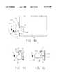
- FIGS. 4, 4a, 4b and 4care illustrative views of the handle swinging between first and second position when inserting a peripheral sled into an enclosure;
- FIG. 5is an illustrative view of a plurality of peripheral enclosures stacked horizontally together
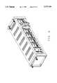
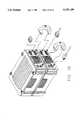
- FIG. 6is an illustrative view of a plurality of peripheral sleds shown loaded into a mass storage enclosure
- FIG. 7is an illustrative view of a typical air-flow pattern in a peripheral enclosure
- FIG. 8is an illustrative view showing how a power supply is inserted into a peripheral enclosure
- FIGS. 9a and 9bare illustrative views of a typical removable power supply showing the latching positions available for use when inserting, retaining and removing the power supply from the enclosure;
- FIG. 10is an illustrative view of a portion of a stack of enclosures showing the means for interconnecting the enclosures;
- FIG. 10ais an illustrative view of the latching mechanism that holds a plurality of stacked enclosures in interlocked connection
- FIG. 11is an illustrative view of a typical rear wall of an enclosure showing the various parts of the cooling means
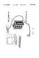
- FIG. 12is an illustrative view showing four enclosures in vertical, stacked arrangement and their interconnection and connection to other computer hardware;
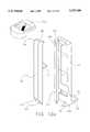
- FIG. 13is an illustrative view of a sled being aligned for insertion into an enclosure
- FIG. 13ais an illustrative view of the rear of the sled shown in FIG. 13;
- FIG. 14is a front plan view of the LCD and keypad that is associated with the peripheral sled;
- FIG. 15is an illustrative view in sequence of the steps needed to rotate the LCD to retain the display in upright orientation when the peripheral sled is stacked vertically as opposed to horizontally;
- FIG. 16is a isometric view showing the internal printed circuit card technology in place of internal cables
- FIGS. 17a and 17bare illustrative views of the two types of SCSI jumper cables used in this invention.
- FIG. 18is an illustrative view of a typical AC jumper cable used in this invention.
- FIGS. 1 and 13the computer subsystem of this invention is shown in FIGS. 1 and 13 to comprise an enclosure 1 formed by broad top and bottom flat walls 3 and 5, respectively, preferably in the size of 6.75 inches wide and 10.75 inches long, held in spaced-apart arrangement by opposed shorter side walls 7 and 9, preferably 2.6 inches high and as long as top and bottom walls 3 and 5, and a rear wall 11 (see FIG. 10) that are all joined along their respective marginal edges 13 to form an enclosure cavity 15 inside said enclosure that is accessible through a front opening 17 that is formed about its periphery by the front edges of top and bottom walls 3 and 5 and side walls 7 and 9.
- Cavity 15may be designed to receive therein an optional peripheral containment sled 19 (see FIG. 13a) and a power supply 21.
- Enclosure 1is preferably made of injection moldable plastic parts so that it is lightweight, yet strong enough to support a plurality of enclosures in vertically stacked arrangement.
- Peripheral containment sled 19is shown in FIG. 13a to comprise broad top and bottom walls 23 and 25, respectively, that are held in spaced-apart arrangement by opposed side walls 27 and 29, a rear wall 31 and a front wall 33, all of said walls joined along their respective marginal edges 35 to form a sled cavity 37 for receipt of a computer peripheral, such as a 4mm DAT or a floppy drive unit, and an elongated power supply 21. More will be said about the peripheral sled 19 later in this description.
- a computer peripheralsuch as a 4mm DAT or a floppy drive unit
- a means 45is provided in enclosure 1 extending rearward from front opening 17 interior of cavity 15 toward rear wall 11 for receiving therealong enclosed sled 19 in controlled alignment.
- means 45preferably comprises a narrow curbing 47 extending interior cavity 15 and raised upward out of bottom wall 5 a short distance, such as 1/4 to 1/2 inch, to confine the path of movement of sled 19 as it is moved into and out of cavity 15.
- Narrow curbing 47may also be extended downward from the interior of top enclosure wall 3 the same or a similar distance to aid in controlling the position of sled 19 in cavity 15.
- another curbing 47may be conveniently placed on the floor of bottom wall 3 adjacent side wall 7 to help confine peripheral sled 19 to one side of cavity 15.
- a radiation shield 49in the form of a foil or similar radiation shield material, be placed inside cavity 15 to completely surround the interior surfaces of top and bottom walls 3 and 5, side walls 7 and 9 and rear wall 11 to reduce the emission of electronic radiation from the enclosure when the peripheral is in use.
- elongated power supply 21comprises elongated top and bottom, narrow walls 53 and 55, respectively, held in spaced-apart relation by spaced-apart side walls 57 and 59, and terminated by a front wall 61 and a rear wall 63, so as to form an elongated, rectangular enclosure having a height designed to fit closely between top and bottom enclosure walls 3 and 5.
- Top, bottom and side walls 53 through 59are preferably made of metal to aid in reducing electronic emissions and in bringing heat, generated in said power supply, out to the surface for ease in cooling.
- a means 65is shown in FIG. 8 and is provided adjacent and aligned with means 45 and also extends rearward from said front opening 17 interior cavity 15 for receiving therealong power supply 21 in modular form to provide power to the peripheral contained in the specific sled 19 inserted in cavity 15.
- sled 19 and power supply 21be positioned in cavity 15 in side-by-side arrangement.
- means 45 and means 65take the form of a common curb 47 between the sled and the power supply to hold both items in controlled alignment.
- means 45 and means 65positioned independent of one another to separately maintain alignment of these items in cavity 15. These separate means may extend upward from the floor of cavity 15 or downward from top wall 3, or they may be a combination of both.
- front wall 33 of sled 19 and front wall 61 of power supply 21are designed to be aligned flush with front opening 17 of enclosure 1 when these items are fully seated in cavity 15. This provides for a convenient, efficient and aesthetically pleasing design to have the peripheral and its own power supply aligned in side-by-side arrangement within one sled. This allows enclosures 1 to be stacked in multiple arrangement as will more clearly be described.
- a means 69is provided in cavity 15 of enclosure 1 for interconnecting the peripheral, housed in sled 19, and power supply 21 interior enclosure 1.
- the preferred embodiment of means 69is a printed circuit board 71 mounted across cavity 15 near rear cavity wall 11.
- On circuit board 71is mounted a forwardly-facing first multipin connector 73 arranged for registered mating engagement with a similar but opposite-sexed (connectable) multipin connector 75 located on sled rear wall 31 and facing aft or outward therefrom (see FIG. 3a).
- a second forwardly-facing multipin connector 77is mounted on printed circuit board 71 and arranged for registered mating engagement with a similar, connectable multipin connector 79 located on rear power supply wall 63, and facing aft or outward therefrom.
- first connector 73 and its counterpart 75are SCSI multipin connectors such as the 80-pin "one-connector" advocated by certain computer groups such as Seagate and Sun Microsystems. Said first and second multipin connectors are interconnected through circuitry contained in printed circuit board 71 to eliminate, almost entirely, the need for SCSI connecting cables that heretofore have become a tangled mass and created heating and impedance problems.
- Means 83is provided in enclosure 1 for air cooling all of the heat generating elements contained within the enclosure.
- Means 83comprises at least one, but preferably a series, of slotted apertures 85 formed in the upper part of enclosure side walls 7 and preferably spanning approximately one-third the length of enclosure 1.
- means 83includes a powerful air fan 87 located inside enclosure rear wall 11, preferably centrally thereof, and adjacent a series of slotted apertures 89 formed in enclosure rear wall 11. Air is drawn by fan 87 in through said apertures 89 and out through the fan assembly.
- both sled 19 and the walls of power supply 21be heavily fenestrated with numerous slots and other apertures so that the powerful draft of air drawn out of cavity 15 by fan 87 is forced about all areas of the peripherals contained in sled 19 and the interior of power supply 21 to carry the heat generated therein out thereof and retain these components and the power supply within their temperature-tolerant levels.
- Thisis especially important when power supply 21 is an autosensing power supply; this is the preferred type of power supply for use in this invention.
- This "suction-type" coolinginsures that cooling air is passed by all areas of the peripheral and the power supply, to eliminate hot spots therein.
- a means 95is provided for interconnecting a plurality of enclosures 1, either horizontally or vertically, to create a small foot print on whatever surface the interconnected enclosures are positioned.
- the vertical stackis shown in FIGS. 1 and 10 while the horizontal stack is shown in FIG. 5.
- Means 95comprises a pair of bars 97, of terminal length, in spaced-apart arrangement on the outside of enclosure side walls 7 and 9, extending from enclosure bottom wall 5 to top wall 3.
- a flange 99extends inward from bar bottom end 101 along the outside of enclosure bottom wall 5. Bars 97 and flanges 99 include exterior surfaces 100 at least a portion of which are spaced-apart from enclosure side walls 7 and 9 and bottom wall 5.
- a channel 103is formed axially along the outside surface of bars 97 for receipt therein of an elongated latch 105 in slideable engagement therewith.
- a hook 107is formed at upper end 109 of latch 105 and arranged to rise above top enclosure wall 3 when said latch is moved to its uppermost position, against a stop 110 situated under said latch.
- a notch 111is formed in lower end 113 of channel 103 for receipt therein of a hook 107 extending upward from a latch 105 carried in a bar 97 of another enclosure 1 positioned therebelow.
- said enclosuresare set one atop another, in aligned arrangement, so that bars 97 of one are aligned with bars 97 of the other enclosure as shown in FIGS. 1 and 10.
- Latch 105 from the lower enclosureis moved upward, by finger pressure, in its channel 103 until hook 107, at the top of said latch, rises to the next set of bars 97 and engages notch 111 at the lower end of the upper bar.
- a ramped depression 115is formed in the lower part of latch 105 and contains a surface irregularity, such as molded dimples 117, to aid the user in sliding latch 105 upward to engage hook 107 with notch 111.
- a small depression 119is formed in top enclosure wall 3 and bars 97 are offset downward the depth of said depression. Flange 99 therefore may be easily made in monolithic form with the bottom end of bar 97 and extend inward over bottom wall 5 as shown.
- a plurality of small, elastomeric pads 121are provided, one in each depression 119, to provide vibration isolation to each enclosure and to insure separation of the bottom wall of one enclosure from the top wall of a lower, interconnected enclosure.
- Bars 97 and latches 105extend outward from the surfaces of enclosure 1 along sidewalls 7 and 9.
- interconnected enclosuresmay be stacked vertically or stacked horizontally.
- elastomeric pads 121set the bottom enclosure above the resting surface to isolate vibration from the peripheral and the cooling air fan.
- the elastomeric nature of bars 97also provide both separation of side walls 7 and 9 from the resting surface but isolate the vibration created inside the enclosure from the surface on which the interlocked enclosures are positioned. In either arrangement, the foot print of the interconnected enclosures is maintained at a minimum to allow the user to have the maximum amount of desk top space for use with other aspects of his/her project.
- jumpers 125are comprised of a short length of multiple conductor wires 127. Over said wire is an elastomeric covering 129. A plurality of closely spaced, plate-like ribs 131 are formed in covering 129 extending outward therefrom about the entire circumference of wire 127 and along the length thereof.
- wire 127 and its covering 129are made wider than thick so that the cross section of jumpers 125 take on a rectangular shape.
- a pair of plugs 133terminates the ends of jumpers 125.
- a jumper containing two multipin SCSI plugsare used to interconnect the data ports of two interconnected enclosures.
- the connectable counterpart plugs or receptacles, to which the SCSI male plugs are attached,are located in enclosure rear wall 11 and are arranged to face outward, one above the other, so that jumper 125 interconnects the plugs in vertical arrangement.
- a pair of widely-spaced screws 135is provided for threadable seating into counterpart threaded bores in rear enclosure wall 11 to retain the plugs in place.
- FIG. 17banother jumper 125 containing similar wire 127, a covering 129, and a smooth covering 132 in preferably rectangular cross section, are terminated with a pair of AC plugs 136, or more preferably one male plug and one female plug, to allow the interconnected enclosures to be plugged in series.
- a skirt or hood 137is formed around the exposed prongs to help in preventing inadvertent physical contact with the user.
- a complementary slot(not shown) is formed inward about the female counterpart of the AC receptacle for receipt therein of skirt 137.
- jumpers 125are arranged to bend about the long axis x--x of the rectangular cross-section of the ribs, as shown in FIG. 17a, so that the curves formed in wires 127 are controlled by ribs 131 into pure 180° bends.
- FIG. 13aAn option in this invention is for sled 19 to be able to be moved into and out of cavity 15 of enclosure 1. As shown in FIG. 13a, this option involves a locking mechanism 141 provided at front sled wall 33.
- FIGS. 4a, 4b and 4cshow mechanism 141 to include a handle 143 that is moveable between a first position, noted as "A” in FIGS. 4a and 4c, wherein sled 39 is inserted in cavity 15 and the peripheral is ready to be interconnected therewith, and a second position, noted as "B" in FIG.
- locking mechanism 141shows a portion of handle 143 being of terminal length for movement through an arc of approximately 900 between first and second positions "A" and "B".
- a pair of handle support lugs 145is connected to the terminal ends of handle 143 and, in turn, are pivotally mounted to sled 19 by pins 147 extending outward from the front portion of side walls 27 and 29 for receipt thereover of a pair of apertures 149 formed in lugs 145.
- a first camming surface 151is formed on the rearward end of lugs 145 and arranged for abutment against a surface 153 formed in enclosure 1 near front opening 17 to retain sled 19 at a specific distance from electrical interconnection when handle 143 is in first position "A".
- a second clasping surface 155is formed on lugs 145 spaced-apart from first camming surface 151 for gradual movement into clasping contact with another locking surface 157 formed on enclosure 1 when handle 143 is moved from first position "A" to second position "B".
- Handle 143is shown to have two elongated ribs 159a and 159b that are positioned at 90° to each other so that one rib is facing forward from sled 19 regardless of the position of handle 143.
- locking mechanism 141is both to obtain positive electrical and physical interconnection between the peripheral and power supply 21 and, simultaneously therewith, insure that sled 19 may achieve this positive interconnection without damage to any of the pins in the SCSI multipin connector.
- Those skilled in the artrealize that the pins of a SCSI multipin connector are rather fragile. Most interconnection between these connectors is accomplished very carefully so as not to bend or otherwise damage any of the pins. Should a pin be damaged, such as by fracture, that particular conductor is not interconnected down the line and therefore, the data stream that is planned for travel along that conductor will not take place. In this event, the computer function will suffer accordingly.
- Surfaces 153 and 157may also be formed on the forward side wall of power supply 21 so that lugs 145 lock against both one enclosure side wall 7 or 9 and the other side wall 57 or 59 of power supply 21. Further, as disclosed in our previous patent application titled, "RACKMOUNT FOR COMPUTER AND MASS STORAGE ENCLOSURE", sled 19 is also fully insertable into electrical interengagement in the mass storage unit disclosed and claimed therein as shown in FIG. 6.
- Another unique feature of this inventionis an LCD display 165 and associated keypad 167 formed in sled front wall 33 for displaying status, diagnostics, and other data.
- a frame 169is provided surrounding LCD 165 and keypad 167 and supports these devices by frictional fit in an aperture 171 formed in sled front wall 33 preferably centered in sled 19.
- a flexible cable 173is attached to the rear of LCD display 165 and keypad 167 and extends inward into the interior of sled 19 into connection with the peripheral housed therein.
- a novel feature of this inventionis that frame 169 is made square as is aperture 171 and cable 173 is of sufficient length to allow said frame to be pried, by finger pressure, out of aperture 171 and rotated 90° and reassembled therein so that LCD display 165 shows the information thereon, in upright form, when enclosures 1 are interlocked and set vertically on a resting surface. This prevents the user from having to turn his/her head sideways to read the display information when the enclosure is rotated from horizontal to vertical.
- Other two-dimensional geometric shapesare also useful therein such as circles and equilateral triangles. As shown in FIG.
- lock 177When the option is provided to withdraw power supply 21 and sled 19 from enclosure cavity 15, a unique lock 177 is employed to prevent unwanted withdrawals of either item from enclosure cavity 15.
- lock 177comprises a cylindrical element or wheel 179 pivotally mounted in a similar-sized aperture 181 formed in power supply front wall 33 for twisting movement through a wheel turning fitting 183 that is shown in FIG. 9b to be a slot 185 for receipt of the edge of a coin.
- a camming surface 187is formed on wheel 179, interior of power supply front wall 33, and rotates in a first slot 189 formed therein.
- Said camming surface 187moves as a function of the position of slot 185 and indicia 191 are provided on power supply front wall 33 such as “lock” and “unlock” to show the position which one would turn slot 185 to in order to achieve the locking or unlocking of power supply 21 in enclosure cavity 15.
- Second and third slots 193 and 195are formed in bottom enclosure wall 5, adjacent front opening 17, and side wall 27 of sled 19. These slots are aligned with first slot 189 so that camming surface 187 can be rotated into either one or both of said slots, by turning slot 185 with a coin, to lock the power supply or the power supply and the sled in the enclosure.
- Wheel 179is normally made of plastic, for cost savings and ease in turning in aperture 181. However, for security reasons, wheel 179 may be made from metal and may contain a common lock and key arrangement, including tumblers (not shown) that is common in the art, so that power supply 21 and/or sled 19 may be locked securely in enclosure 1.
Landscapes
- Engineering & Computer Science (AREA)
- Theoretical Computer Science (AREA)
- General Engineering & Computer Science (AREA)
- Physics & Mathematics (AREA)
- General Physics & Mathematics (AREA)
- Human Computer Interaction (AREA)
- Power Engineering (AREA)
- Computer Hardware Design (AREA)
- Cooling Or The Like Of Electrical Apparatus (AREA)
Abstract
Description
This application is a Continuation-in-Part of our previously filed patent applications, one titled, "SELF-CAPTURING ARTICULATING CHEST HANDLE", filed Jan. 10, 1994 and given Ser. No. 08/179,082 now U.S. Pat. No. 5,400,470; and the other titled, "RACKMOUNT FOR COMPUTER AND MASS STORAGE ENCLOSURE", filed Jun. 24, 1994, and given Ser. No. 08/265,208 now U.S. Pat. No. 5,505,533 and a continuation of our previously filed patent application titled HIGH PERFORMANCE MASS STORAGE SUBSYSTEM, filed Aug. 24, 1994 and given Ser. No. 08/295,280.
1. Field of the Invention
This invention relates to the field of computer peripheral enclosures. More particularly, it pertains to a mass storage subsystem using interlocking modular stackability.
2. Description of the Prior Art
The growth rate in computer usage has been tremendous. There appears no end in sight and growth should continue at its astounding rate. In response thereto, work station performance has doubled each year for at least the last decade. Device capacity and transfer rates have also doubled approximately each year over the same period of time. Unfortunately, mass storage enclosures have not kept pace.
It has become common to use more than one peripheral, such as a disk drive, than that which is provided with the personal computer or work station. It is also common to employ DAT drives, disk drives and CDs with the computer. At present, these devices are purchased individually and require interconnection with the computer through elongated multiconductor cables having multipin connectors located at each end. These are SCSI or "scuzzy" cables. The utilization of these plug-in type units, in their individual form, has caused many problems.
The individual units are not built for physical strength so that they cannot be stacked but must be placed individually on a desk top. Employment of three or more such units causes a general cluttering about the desk top. As this "foot print" becomes enlarged, the work space on the desk top shrinks to the point where the units must be stacked one on top of another to save desk top space.
Even if they are stacked, the SCSI cables become twisted and tangled, giving rise to impedance and noise problems. This can result in unpredictable and random errors that can both crash the entire system and/or corrupt data. The units are generally connected in series which causes substantial drain on the computer power supply, to serve the separate power supplies, and which tends to create voltage fluctuations in the units and possible degradation in computer functions. While these units may remain cool using their own internal cooling fans, interconnecting the units with a computer often increases the workload on the individual unit giving rise to heat problems. Modern designs in computer peripherals stress minimized silhouetting which reduces the internal volume of the peripheral and degrades air cooling. As the cables tangle, heat problems and other difficulties continue without relief and the efficient use of peripherals is degraded.
With present interconnected peripherals, the extraction of one peripheral from the stack requires shut-down of the entire computer system and realignment of the remaining units. This causes significant down time and introduces a serious potential for lost data.
This invention is a high performance, mass storage, subsystem utilizing peripheral containment sleds for housing computer peripherals and a subsystem comprising stackable, interlocking, modular peripheral containment enclosures for joining the sled- mounted peripherals together in unique and efficient geometries. The novel sleds house the peripherals, such as DAT units and floppy disk drives, in a strong, well-ventilated containment sled that is easily and safely insertable into containment enclosures that isolate the peripherals with their own separate power supply and a novel exhaust air cooling system to produce an extremely handleable and reliable unit.
The SCSI cables are replaced in large part by printed circuit boards to reduce the impedance and noise problems virtually to extinction. The containment enclosures are stackable, both horizontally and vertically, into a multitude of closely-spaced peripherals having an extremely small desk-top foot print, while at the same time, being contained in a physically strong structure having expanded cooling facilities that allow the individual peripherals to be loaded to their maximum potential.
The stackable units are interlockable through a novel latching system that eliminates the need for screws and screwdrivers. The latching system utilizes finger tip control. The stackable units may be set in horizontal or vertical arrangement, on a flat desk surface, and the unique interconnection establishes a controlled space between the desk surface and the closest wall of the enclosure to insure a free path for air to pass during its cooling activity. With this novel stacking arrangement, one or more peripherals may be disconnected from the stack without interfering with the on-going transactions taking place within the computer. This "hot disk" removability saves significant down time on the computer.
Each sled contains its own power supply thereby reducing strain on the computer power supply and eliminating the potential for lost or damaged data due to voltage fluctuation. The overall mass storage subsystem is presented as a clean and neat industrial design bringing order to an otherwise chaotic practice. Unique jumpers, using short SCSI and power cables are used to interconnect the various enclosures. As an option, a sled may contain a LCD along with a keypad for target ID setting, device power on/off, status and diagnostic messages. A unique feature of this invention is that the LCD and keypad may be rotated to accommodate horizontal as well as vertical stacking to retain the readouts in easily readable, vertical format.
A novel insertion device is incorporated in the sled to allow it to be brought into controlled electrical connection with the internal electronics of the enclosure. Without this device, the tendency to ram the sled home in the enclosure would present significant potential for damage to the pins of the interconnecting multi-pin connector. Utilizing this unique insertion device prevents anything other than controlled interconnection between the connectors so as to prolong the useful life of the sled.
Accordingly, the main object of this invention is a high-performance, mass storage, subsystem that provides controlled stackability of computer peripherals in a manner that maximizes their individual potential and minimizes the problems presently encountered with interconnection of these peripherals. Other objects of the invention include a mass storage subsystem that is useful with rackmounted enclosures for work stations and servers; a storage subsystem that enhances the usability of various peripherals for computer work stations; a subsystem that incorporates interlocking modular stackability, in both horizontal and vertical arrangements, to decrease the overall footprint of the stacked peripherals while maximizing the utilization thereof; a subsystem that eliminates tangles from SCSI cables and the impedance and heating problems associated therewith by using extremely short-length external SCSI and AC jumpers whose bends are controlled into neat, geometric curves; a peripheral enclosure utilizing a front-panel LCD and keypad for status and diagnostic messages that may be rotated to remain upright when the peripherals are stacked either horizontally or vertically; a mass storage subsystem from which various peripherals and power supplies may be removed by "hot disk" state-of-the-art electronic processes to increase computer time and reduce down time; a mass storage system that integrates extra disk and tape subsystems into a computer work station for increasing the capacity thereof; a mass storage subsystem utilizing internal printed circuit cards and external jumpers in substitution for presently utilized elongated SCSI cables for both data transfer and power transfer; a subsystem utilizing an exhaust air-cooling system that insures the units to be operated within factory tolerances; a mass storage subsystem that is modular in concept and easily expandable wherein the stacking is done without the need for screws and other threaded devices; and a storage subsystem that insures the peripherals are maintained above the plane of whatever surface they are placed upon.
These and other objects of the invention will become more apparent when reading the following Description of the Preferred Embodiment taken together with the drawings appended hereto. The scope of protection sought by the inventors may be gleaned from a fair reading of the Claims that conclude this Specification.
FIG. 1 is an illustrative view of a plurality of peripheral enclosures stacked horizontally together;
FIG. 2 is an illustrative view of the rear of a pair of enclosures stacked together in a subsystem showing the use of AC and SCSI jumpers to replace cables;
FIG. 3 is an illustrative view of a modular power supply that is insertable in a sled that will become part of a stackable subsystem;
FIG. 3a is an illustrative of the rear of the modular power supply shown in FIG. 3;
FIGS. 4, 4a, 4b and 4c are illustrative views of the handle swinging between first and second position when inserting a peripheral sled into an enclosure;
FIG. 5 is an illustrative view of a plurality of peripheral enclosures stacked horizontally together;
FIG. 6 is an illustrative view of a plurality of peripheral sleds shown loaded into a mass storage enclosure;
FIG. 7 is an illustrative view of a typical air-flow pattern in a peripheral enclosure;
FIG. 8 is an illustrative view showing how a power supply is inserted into a peripheral enclosure;
FIGS. 9a and 9b are illustrative views of a typical removable power supply showing the latching positions available for use when inserting, retaining and removing the power supply from the enclosure;
FIG. 10 is an illustrative view of a portion of a stack of enclosures showing the means for interconnecting the enclosures;
FIG. 10a is an illustrative view of the latching mechanism that holds a plurality of stacked enclosures in interlocked connection;
FIG. 11 is an illustrative view of a typical rear wall of an enclosure showing the various parts of the cooling means;
FIG. 12 is an illustrative view showing four enclosures in vertical, stacked arrangement and their interconnection and connection to other computer hardware;
FIG. 13 is an illustrative view of a sled being aligned for insertion into an enclosure;
FIG. 13a is an illustrative view of the rear of the sled shown in FIG. 13;
FIG. 14 is a front plan view of the LCD and keypad that is associated with the peripheral sled;
FIG. 15 is an illustrative view in sequence of the steps needed to rotate the LCD to retain the display in upright orientation when the peripheral sled is stacked vertically as opposed to horizontally;
FIG. 16 is a isometric view showing the internal printed circuit card technology in place of internal cables;
FIGS. 17a and 17b are illustrative views of the two types of SCSI jumper cables used in this invention;
FIG. 18 is an illustrative view of a typical AC jumper cable used in this invention;
Turning now to the drawings wherein like elements are identified with like numerals throughout the twenty-five figures, the computer subsystem of this invention is shown in FIGS. 1 and 13 to comprise anenclosure 1 formed by broad top and bottomflat walls shorter side walls bottom walls marginal edges 13 to form anenclosure cavity 15 inside said enclosure that is accessible through afront opening 17 that is formed about its periphery by the front edges of top andbottom walls side walls Cavity 15 may be designed to receive therein an optional peripheral containment sled 19 (see FIG. 13a) and apower supply 21.Enclosure 1 is preferably made of injection moldable plastic parts so that it is lightweight, yet strong enough to support a plurality of enclosures in vertically stacked arrangement.
A means 45 is provided inenclosure 1 extending rearward from front opening 17 interior ofcavity 15 towardrear wall 11 for receiving therealong enclosedsled 19 in controlled alignment. As shown in FIG. 13, means 45 preferably comprises a narrow curbing 47 extendinginterior cavity 15 and raised upward out of bottom wall 5 a short distance, such as 1/4 to 1/2 inch, to confine the path of movement ofsled 19 as it is moved into and out ofcavity 15. Narrow curbing 47 may also be extended downward from the interior oftop enclosure wall 3 the same or a similar distance to aid in controlling the position ofsled 19 incavity 15. In addition, another curbing 47 may be conveniently placed on the floor ofbottom wall 3adjacent side wall 7 to help confineperipheral sled 19 to one side ofcavity 15.
It is preferred that aradiation shield 49, in the form of a foil or similar radiation shield material, be placed insidecavity 15 to completely surround the interior surfaces of top andbottom walls side walls rear wall 11 to reduce the emission of electronic radiation from the enclosure when the peripheral is in use.
As shown in FIG. 3,elongated power supply 21 comprises elongated top and bottom,narrow walls side walls front wall 61 and arear wall 63, so as to form an elongated, rectangular enclosure having a height designed to fit closely between top andbottom enclosure walls side walls 53 through 59, are preferably made of metal to aid in reducing electronic emissions and in bringing heat, generated in said power supply, out to the surface for ease in cooling.
A means 65 is shown in FIG. 8 and is provided adjacent and aligned withmeans 45 and also extends rearward from said front opening 17interior cavity 15 for receivingtherealong power supply 21 in modular form to provide power to the peripheral contained in thespecific sled 19 inserted incavity 15. As shown in FIGS. 8 and 13, it is preferred thatsled 19 andpower supply 21 be positioned incavity 15 in side-by-side arrangement. In this preferred arrangement, means 45 and means 65 take the form of acommon curb 47 between the sled and the power supply to hold both items in controlled alignment. However, it is within the spirit and scope of this invention to havemeans 45 and means 65 positioned independent of one another to separately maintain alignment of these items incavity 15. These separate means may extend upward from the floor ofcavity 15 or downward fromtop wall 3, or they may be a combination of both.
As shown in FIG. 1,front wall 33 ofsled 19 andfront wall 61 ofpower supply 21 are designed to be aligned flush withfront opening 17 ofenclosure 1 when these items are fully seated incavity 15. This provides for a convenient, efficient and aesthetically pleasing design to have the peripheral and its own power supply aligned in side-by-side arrangement within one sled. This allowsenclosures 1 to be stacked in multiple arrangement as will more clearly be described.
As shown in FIG. 16, ameans 69 is provided incavity 15 ofenclosure 1 for interconnecting the peripheral, housed insled 19, andpower supply 21interior enclosure 1. The preferred embodiment ofmeans 69 is a printedcircuit board 71 mounted acrosscavity 15 nearrear cavity wall 11. Oncircuit board 71 is mounted a forwardly-facing firstmultipin connector 73 arranged for registered mating engagement with a similar but opposite-sexed (connectable)multipin connector 75 located on sledrear wall 31 and facing aft or outward therefrom (see FIG. 3a). A second forwardly-facingmultipin connector 77 is mounted on printedcircuit board 71 and arranged for registered mating engagement with a similar, connectablemultipin connector 79 located on rearpower supply wall 63, and facing aft or outward therefrom. It is preferred thatfirst connector 73 and itscounterpart 75 are SCSI multipin connectors such as the 80-pin "one-connector" advocated by certain computer groups such as Seagate and Sun Microsystems. Said first and second multipin connectors are interconnected through circuitry contained in printedcircuit board 71 to eliminate, almost entirely, the need for SCSI connecting cables that heretofore have become a tangled mass and created heating and impedance problems.
As shown in FIGS. 7 and 11, means 83 is provided inenclosure 1 for air cooling all of the heat generating elements contained within the enclosure. Means 83 comprises at least one, but preferably a series, of slottedapertures 85 formed in the upper part ofenclosure side walls 7 and preferably spanning approximately one-third the length ofenclosure 1. In addition, means 83 includes apowerful air fan 87 located inside enclosurerear wall 11, preferably centrally thereof, and adjacent a series of slotted apertures 89 formed in enclosurerear wall 11. Air is drawn byfan 87 in through said apertures 89 and out through the fan assembly. It is preferred that bothsled 19 and the walls ofpower supply 21 be heavily fenestrated with numerous slots and other apertures so that the powerful draft of air drawn out ofcavity 15 byfan 87 is forced about all areas of the peripherals contained insled 19 and the interior ofpower supply 21 to carry the heat generated therein out thereof and retain these components and the power supply within their temperature-tolerant levels. This is especially important whenpower supply 21 is an autosensing power supply; this is the preferred type of power supply for use in this invention. This "suction-type" cooling insures that cooling air is passed by all areas of the peripheral and the power supply, to eliminate hot spots therein.
As shown in FIGS. 10 and 10a, ameans 95 is provided for interconnecting a plurality ofenclosures 1, either horizontally or vertically, to create a small foot print on whatever surface the interconnected enclosures are positioned. The vertical stack is shown in FIGS. 1 and 10 while the horizontal stack is shown in FIG. 5.Means 95 comprises a pair ofbars 97, of terminal length, in spaced-apart arrangement on the outside ofenclosure side walls bottom wall 5 totop wall 3. Aflange 99 extends inward from barbottom end 101 along the outside of enclosurebottom wall 5.Bars 97 andflanges 99 includeexterior surfaces 100 at least a portion of which are spaced-apart fromenclosure side walls bottom wall 5. Achannel 103 is formed axially along the outside surface ofbars 97 for receipt therein of anelongated latch 105 in slideable engagement therewith. Ahook 107 is formed atupper end 109 oflatch 105 and arranged to rise abovetop enclosure wall 3 when said latch is moved to its uppermost position, against astop 110 situated under said latch. Anotch 111 is formed inlower end 113 ofchannel 103 for receipt therein of ahook 107 extending upward from alatch 105 carried in abar 97 of anotherenclosure 1 positioned therebelow. To interlock two or more enclosures, said enclosures are set one atop another, in aligned arrangement, so thatbars 97 of one are aligned withbars 97 of the other enclosure as shown in FIGS. 1 and 10. Latch 105 from the lower enclosure is moved upward, by finger pressure, in itschannel 103 untilhook 107, at the top of said latch, rises to the next set ofbars 97 and engages notch 111 at the lower end of the upper bar. A ramped depression 115 is formed in the lower part oflatch 105 and contains a surface irregularity, such as moldeddimples 117, to aid the user in slidinglatch 105 upward to engagehook 107 withnotch 111. Asmall depression 119 is formed intop enclosure wall 3 and bars 97 are offset downward the depth of said depression.Flange 99 therefore may be easily made in monolithic form with the bottom end ofbar 97 and extend inward overbottom wall 5 as shown. A plurality of small,elastomeric pads 121 are provided, one in eachdepression 119, to provide vibration isolation to each enclosure and to insure separation of the bottom wall of one enclosure from the top wall of a lower, interconnected enclosure.
The stacked enclosures are shown interconnected through one ormore jumpers 125. These jumpers are short in length and do not intertangle. They reduce impedance and noise problems to virtual elimination. As shown in FIGS. 2, 10, 12, 17b and 18, two kinds of jumpers are utilized in this invention, both having similar characteristics, and are provided in two kinds of designs.Jumpers 125 are comprised of a short length ofmultiple conductor wires 127. Over said wire is anelastomeric covering 129. A plurality of closely spaced, plate-like ribs 131 are formed in covering 129 extending outward therefrom about the entire circumference ofwire 127 and along the length thereof. It is preferred thatwire 127 and its covering 129 are made wider than thick so that the cross section ofjumpers 125 take on a rectangular shape. A pair ofplugs 133 terminates the ends ofjumpers 125. As shown in FIG. 10, a jumper containing two multipin SCSI plugs are used to interconnect the data ports of two interconnected enclosures. The connectable counterpart plugs or receptacles, to which the SCSI male plugs are attached, are located in enclosurerear wall 11 and are arranged to face outward, one above the other, so thatjumper 125 interconnects the plugs in vertical arrangement. As with most SCSI plugs, a pair of widely-spacedscrews 135 is provided for threadable seating into counterpart threaded bores inrear enclosure wall 11 to retain the plugs in place.
In another embodiment, shown in FIG. 17b anotherjumper 125 containingsimilar wire 127, a covering 129, and asmooth covering 132 in preferably rectangular cross section, are terminated with a pair of AC plugs 136, or more preferably one male plug and one female plug, to allow the interconnected enclosures to be plugged in series. With respect to the plug containing exposed prongs, as shown in FIG. 17b, a skirt orhood 137 is formed around the exposed prongs to help in preventing inadvertent physical contact with the user. A complementary slot (not shown) is formed inward about the female counterpart of the AC receptacle for receipt therein ofskirt 137. In the case ofribs 131, it is preferred thatjumpers 125 are arranged to bend about the long axis x--x of the rectangular cross-section of the ribs, as shown in FIG. 17a, so that the curves formed inwires 127 are controlled byribs 131 into pure 180° bends.
An option in this invention is forsled 19 to be able to be moved into and out ofcavity 15 ofenclosure 1. As shown in FIG. 13a, this option involves alocking mechanism 141 provided atfront sled wall 33. FIGS. 4a, 4b and 4cshow mechanism 141 to include ahandle 143 that is moveable between a first position, noted as "A" in FIGS. 4a and 4c, whereinsled 39 is inserted incavity 15 and the peripheral is ready to be interconnected therewith, and a second position, noted as "B" in FIG. 4b, whereinsled 19 is locked intoenclosure 1 and the peripheral contained in said sled is electrically interconnected therewith and further, wherein the movement ofhandle 143 between first and second positions "A" and "B", respectively, accomplishes the act of lockingsled 19 and interconnecting the peripheral.
As shown, the preferred embodiment oflocking mechanism 141 shows a portion ofhandle 143 being of terminal length for movement through an arc of approximately 900 between first and second positions "A" and "B". A pair of handle support lugs 145 is connected to the terminal ends ofhandle 143 and, in turn, are pivotally mounted tosled 19 bypins 147 extending outward from the front portion ofside walls apertures 149 formed inlugs 145. Afirst camming surface 151 is formed on the rearward end oflugs 145 and arranged for abutment against asurface 153 formed inenclosure 1 near front opening 17 to retainsled 19 at a specific distance from electrical interconnection whenhandle 143 is in first position "A".
Asecond clasping surface 155 is formed onlugs 145 spaced-apart fromfirst camming surface 151 for gradual movement into clasping contact with another lockingsurface 157 formed onenclosure 1 whenhandle 143 is moved from first position "A" to second position "B". Handle 143 is shown to have two elongatedribs sled 19 regardless of the position ofhandle 143.
The purpose of lockingmechanism 141 is both to obtain positive electrical and physical interconnection between the peripheral andpower supply 21 and, simultaneously therewith, insure thatsled 19 may achieve this positive interconnection without damage to any of the pins in the SCSI multipin connector. Those skilled in the art realize that the pins of a SCSI multipin connector are rather fragile. Most interconnection between these connectors is accomplished very carefully so as not to bend or otherwise damage any of the pins. Should a pin be damaged, such as by fracture, that particular conductor is not interconnected down the line and therefore, the data stream that is planned for travel along that conductor will not take place. In this event, the computer function will suffer accordingly.
Whensled 19 is inserted intocavity 15 and pushed inward, the two interconnectable multipin connectors located respectively on sledrear wall 31 and fixedconnector 73, are prevented from interconnecting through the abutment offirst camming surface 151 againstsurface 153 inmechanism 141. This brings the motion ofsled 19 to a full stop. At this point, handle 143 is in its first position. To complete the insertion ofsled 19 intocavity 15 and achieve electrical and physical interconnection between the respective SCSI connectors, handle 143 is moved downward towards its second position "B". During this travel,second clasping surface 155 formed onlugs 145 will move into clasping engagement withsecond clasping surface 155 and slowly drawsled 19 into final insertion incavity 15. It is this controlled movement ofsled 19 only by the movement ofhandle 143 that causes physical and electrical interconnection ofsled 19 incavity 15. This smooth connecting movement also prevents the individual pins of the SCSI connectors from entering into interfering motion with each other and accordingly prolongs the life and the viability of the interconnection. In addition, the use ofhandle 143 and software contained inPC board 71 allows a peripheral to be disconnected through movement ofhandle 143 and removed from its sled without shutting down the entire computer network. This is referred to as "hot disk" removability and allows additions and deletions of peripherals to the system while the system is fully functional.
Another unique feature of this invention is anLCD display 165 and associatedkeypad 167 formed insled front wall 33 for displaying status, diagnostics, and other data. As shown in FIGS. 1, and13a 15, aframe 169 is provided surroundingLCD 165 andkeypad 167 and supports these devices by frictional fit in anaperture 171 formed insled front wall 33 preferably centered insled 19. Aflexible cable 173 is attached to the rear ofLCD display 165 andkeypad 167 and extends inward into the interior ofsled 19 into connection with the peripheral housed therein.
A novel feature of this invention is thatframe 169 is made square as isaperture 171 andcable 173 is of sufficient length to allow said frame to be pried, by finger pressure, out ofaperture 171 and rotated 90° and reassembled therein so thatLCD display 165 shows the information thereon, in upright form, whenenclosures 1 are interlocked and set vertically on a resting surface. This prevents the user from having to turn his/her head sideways to read the display information when the enclosure is rotated from horizontal to vertical. Other two-dimensional geometric shapes are also useful therein such as circles and equilateral triangles. As shown in FIG. 15, to changeLCD display 165 from horizontal to vertical orientation, one need only pry one oflugs 145 off of its associatedpin 147 and displacehandle 143 outward from thefront wall 33 ofsled 19, then simply pryLCD display frame 169 from its frictional fit inaperture 171, rotate said frame 90° and then press it back into frictional fit inaperture 171.
When the option is provided to withdrawpower supply 21 andsled 19 fromenclosure cavity 15, aunique lock 177 is employed to prevent unwanted withdrawals of either item fromenclosure cavity 15. As shown in FIGS. 9a and 9b,lock 177 comprises a cylindrical element orwheel 179 pivotally mounted in a similar-sized aperture 181 formed in powersupply front wall 33 for twisting movement through a wheel turning fitting 183 that is shown in FIG. 9b to be aslot 185 for receipt of the edge of a coin. Acamming surface 187 is formed onwheel 179, interior of powersupply front wall 33, and rotates in afirst slot 189 formed therein. Saidcamming surface 187 moves as a function of the position ofslot 185 andindicia 191 are provided on powersupply front wall 33 such as "lock" and "unlock" to show the position which one would turnslot 185 to in order to achieve the locking or unlocking ofpower supply 21 inenclosure cavity 15.
Second andthird slots bottom enclosure wall 5,adjacent front opening 17, andside wall 27 ofsled 19. These slots are aligned withfirst slot 189 so thatcamming surface 187 can be rotated into either one or both of said slots, by turningslot 185 with a coin, to lock the power supply or the power supply and the sled in the enclosure.Wheel 179 is normally made of plastic, for cost savings and ease in turning inaperture 181. However, for security reasons,wheel 179 may be made from metal and may contain a common lock and key arrangement, including tumblers (not shown) that is common in the art, so thatpower supply 21 and/orsled 19 may be locked securely inenclosure 1.
While this invention has been described with respect to a preferred embodiment, one may modify the various elements and still remain within the scope of the claims that conclude this specification. It is the inventors' position that any modification which performs substantially the same function in substantially the same way to produce substantially the same result is within the scope and spirit of this invention and the claims.
Claims (2)
1. A computer subsystem comprising at least two individual modular peripheral containment enclosures for stacking in horizontal or vertical alignment, each enclosure comprising:
a) broad top and bottom walls held in spaced-apart arrangement by opposed shorter side walls and a rear wall, said walls joined along their respective marginal edges to form a front opening and a cavity in said enclosure accessible through said front opening;
b) a sled for receipt therein of a computer peripheral, said sled receivable in said cavity through said front opening in said enclosure;
c) means extending rearward from said front enclosure opening interior said cavity for receiving therealong said sled in controlled alignment, said sled including a front face that aligns flush against said enclosure front opening when said sled is fully seated in said cavity;
d) means for electrically interconnecting the peripheral in said enclosure to the rest of the computer subsystem including a connector interior said cavity mateable with the peripheral in said sled and with the computer subsystem exterior said sled;
e) means for providing air cooling throughout said cavity, unimpeded by the stacking arrangement of said enclosures, including an aperture formed in at least one of said walls of each said enclosure for passage of air therethrough; and,
f) means for interconnecting multiples of said enclosures in fixed horizontal or vertical, self-supporting arrangement for positioning on a surface, that does not adversely affect the cooling throughout said cavity by said cooling means, including means for maintaining a space between said surface and said enclosure wall nearest said surface wherein said means for interconnecting multiples of said enclosures includes:
i) first and second bars in spaced-apart engagement attached along the outside of said first enclosure side walls and extending from said bottom wall to said top wall;
ii) a flange extending from said first bar inward, along said bottom wall;
iii) said first bar and said flange including exterior surfaces, at least a portion of which are spaced from said first enclosure wall;
iv) an elongated latch and a channel formed in said first and second bars for receipt therein of said elongated latch in slidable engagement therewith; and,
v) a hook formed in the upper end of said elongated latch extending above said first enclosure top wall and a notch formed in the lower portion of the first bar of a second enclosure stacked atop said first enclosure so that said elongated latch may be moved upward to engage said notch in said first bar for interconnecting said first and second said enclosures.
2. The subsystem of claim 1 further including a depression formed in said top wall adjacent each said bar and further including soft pads having a thickness greater than the depths of said depressions and of a size to fit in said depressions for insertion therein to provide vibration isolation to said enclosures and to space said enclosures apart from each other when arranged in stacked, interlocked attachment therebetween.
Priority Applications (1)
| Application Number | Priority Date | Filing Date | Title |
|---|---|---|---|
| US08/760,726US5737189A (en) | 1994-01-10 | 1996-12-05 | High performance mass storage subsystem |
Applications Claiming Priority (4)
| Application Number | Priority Date | Filing Date | Title |
|---|---|---|---|
| US08/179,082US5400470A (en) | 1994-01-10 | 1994-01-10 | Self-capturing articulating chest handle |
| US08/265,208US5505533A (en) | 1994-01-10 | 1994-06-24 | Rackmount for computer and mass storage enclosure |
| US29528094A | 1994-08-24 | 1994-08-24 | |
| US08/760,726US5737189A (en) | 1994-01-10 | 1996-12-05 | High performance mass storage subsystem |
Related Parent Applications (3)
| Application Number | Title | Priority Date | Filing Date |
|---|---|---|---|
| US08/179,082Continuation-In-PartUS5400470A (en) | 1994-01-10 | 1994-01-10 | Self-capturing articulating chest handle |
| US08/265,208Continuation-In-PartUS5505533A (en) | 1994-01-10 | 1994-06-24 | Rackmount for computer and mass storage enclosure |
| US29528094AContinuation | 1994-01-10 | 1994-08-24 |
Publications (1)
| Publication Number | Publication Date |
|---|---|
| US5737189Atrue US5737189A (en) | 1998-04-07 |
Family
ID=27391068
Family Applications (1)
| Application Number | Title | Priority Date | Filing Date |
|---|---|---|---|
| US08/760,726Expired - Fee RelatedUS5737189A (en) | 1994-01-10 | 1996-12-05 | High performance mass storage subsystem |
Country Status (1)
| Country | Link |
|---|---|
| US (1) | US5737189A (en) |
Cited By (84)
| Publication number | Priority date | Publication date | Assignee | Title |
|---|---|---|---|---|
| US5801448A (en)* | 1996-05-20 | 1998-09-01 | Micron Technology, Inc. | Conductive lines on the back side of wafers and dice for semiconductor interconnects |
| US5909357A (en)* | 1997-04-24 | 1999-06-01 | Orr; Tom | Vertically stacked computer modules shaped to indicate compatibility with vertical cooling shaft extending throughout |
| USD412322S (en)* | 1998-09-28 | 1999-07-27 | Commercial & Industrial Design Co., Inc. | Data port coupler |
| US5940274A (en)* | 1996-02-05 | 1999-08-17 | Hitachi, Ltd. | Casing for computer and computer employing the same casing with removable rear cable cover |
| US5955700A (en)* | 1997-12-30 | 1999-09-21 | Motorola, Inc. | Housing unit including a latching mechanism with a cam |
| USD418816S (en)* | 1998-09-28 | 2000-01-11 | Commercial & Industrial Design Co., Inc. | Modular power connector |
| US6050658A (en)* | 1998-02-23 | 2000-04-18 | Richmount Computer Limited | Carrier for an electronic device |
| US6056256A (en)* | 1998-12-18 | 2000-05-02 | Ponce; Karen Elizabeth Rivera | Method for separating electronic equipment modules using spacer devices |
| US6061321A (en)* | 1997-09-09 | 2000-05-09 | Fujitsu Limited | Deck lock mechanism and library apparatus |
| US6073333A (en)* | 1997-04-24 | 2000-06-13 | Orr; Tom | Method for manufacture and assembly of computers |
| US6104445A (en)* | 1997-10-23 | 2000-08-15 | Samsung Electronics Co., Ltd. | Monitor housing with integral rack for storing recording media |
| US6141221A (en)* | 1999-08-03 | 2000-10-31 | Belkin Components | Universal serial bus docking station |
| US6148352A (en)* | 1997-12-24 | 2000-11-14 | International Business Machines Corporation | Scalable modular data storage system |
| US6172875B1 (en)* | 1998-11-17 | 2001-01-09 | Rockwell Technologies, Llc | Programmable logic controller module assembly and locking system |
| WO2001004764A1 (en)* | 1999-07-08 | 2001-01-18 | Xircom, Inc. | Modular, user configurable port expansion system |
| WO2001014979A1 (en)* | 1999-08-23 | 2001-03-01 | Honeywell Inc. | Scalable data collection and computing apparatus |
| US6201692B1 (en)* | 1999-03-31 | 2001-03-13 | International Business Machines Corporation | Disk drive enclosure optimized for mixed slim and half high drive size |
| US6249671B1 (en)* | 1998-06-05 | 2001-06-19 | Lxe, Inc. | Aesthetic enclosure for a wireless network access point |
| US6272573B1 (en) | 1997-12-24 | 2001-08-07 | International Business Machines Corporation | Scalable modular data storage system |
| USD447483S1 (en) | 2000-02-24 | 2001-09-04 | Jeff Wu | Stackable rack server |
| US6310779B1 (en)* | 1999-03-08 | 2001-10-30 | Asustek Computer Inc. | System for attaching cartridge-type CPU to a board |
| US6456492B1 (en)* | 1999-07-09 | 2002-09-24 | Asustek Computer Inc. | Expansion apparatus for a portable computer |
| US6462953B2 (en) | 1999-08-03 | 2002-10-08 | Belkin Components | Universal serial bus module and system |
| US6469901B1 (en) | 2000-05-15 | 2002-10-22 | 3C Interactive, Inc. | System and method for cartridge-based, geometry-variant scalable electronic systems |
| WO2002088974A1 (en)* | 2001-05-01 | 2002-11-07 | Sun Microsystems Inc. | Method for interconnecting modular computer system components |
| US20030161101A1 (en)* | 2001-06-29 | 2003-08-28 | Hillyard David R. | High availability small foot-print server |
| US6628513B1 (en)* | 2001-06-07 | 2003-09-30 | Emc Corporation | Mass storage device mounting system |
| US6650535B1 (en)* | 1999-07-23 | 2003-11-18 | Dell Products L.P. | Fanless power supply |
| US20040070923A1 (en)* | 2002-10-10 | 2004-04-15 | D-Link Corporation | Housing structure of network device |
| US20040246672A1 (en)* | 2003-07-21 | 2004-12-09 | Chia-Jen Wang | External connection device for a storage device |
| US20050047099A1 (en)* | 2003-08-26 | 2005-03-03 | Belkin Corporation | Universal serial bus hub and method of manufacturing same |
| US20050094355A1 (en)* | 2003-08-26 | 2005-05-05 | Belkin Corporation | Universal serial bus hub and method of manufacturing same |
| USD510091S1 (en) | 2003-08-26 | 2005-09-27 | Belkin Corporation | Universal serial bus hub |
| USD512718S1 (en) | 2003-08-26 | 2005-12-13 | Belkin Corporation | Universal serial bus hub |
| USD518704S1 (en)* | 2002-08-06 | 2006-04-11 | Quanta Computer Inc. | Bracket for stackable device |
| USD523014S1 (en)* | 2005-03-03 | 2006-06-13 | Cisco Technology, Inc. | Single height housing |
| USD524815S1 (en)* | 2005-03-03 | 2006-07-11 | Cisco Technology, Inc. | Double height housing |
| USD529903S1 (en) | 2005-03-03 | 2006-10-10 | Cisco Technology, Inc. | Gateway housing |
| USD530717S1 (en) | 2005-04-15 | 2006-10-24 | Belkin Corporation | USB hub |
| US20060242339A1 (en)* | 2005-04-20 | 2006-10-26 | Inostor Corporation | Reconfigurable computing array without chassis |
| US20060286840A1 (en)* | 2005-06-20 | 2006-12-21 | Belkin Corporation | Multi-standard connection hub and method of manufacturing same |
| USD536333S1 (en) | 2005-03-03 | 2007-02-06 | Cisco Technology, Inc. | Single height gateway housing |
| USD536696S1 (en) | 2005-03-03 | 2007-02-13 | Cisco Technology, Inc. | Double height gateway housing |
| US20070177294A1 (en)* | 2006-01-30 | 2007-08-02 | Nobuhiro Adachi | Method for solving heat dissipation problems of computer system and modularized computer system for performing the method |
| US7293135B1 (en) | 2004-12-30 | 2007-11-06 | Emc Corporation | Invertible disk drive connection scheme |
| US7304855B1 (en)* | 2003-03-03 | 2007-12-04 | Storage Technology Corporation | Canister-based storage system |
| US20070297150A1 (en)* | 2004-11-23 | 2007-12-27 | Linak A/S | Control Box For Electrical Actuators,Especially For Adjustable Furniture |
| US20080061661A1 (en)* | 2006-08-09 | 2008-03-13 | Aopen Inc. | Common framework for stackable modulator personal computer |
| US20080178080A1 (en)* | 2007-01-22 | 2008-07-24 | Winston Bumpus | Removable hard disk with display information |
| US20080200064A1 (en)* | 2007-01-05 | 2008-08-21 | Belkin International, Inc. | Electrical Grommet Device |
| US20080235440A1 (en)* | 2007-03-22 | 2008-09-25 | Le Trung V | Memory device |
| US20080285221A1 (en)* | 2007-04-02 | 2008-11-20 | Bruce Imsand | Portable Computer with Space Efficient Cubic Configuration |
| US20100224689A1 (en)* | 2009-03-06 | 2010-09-09 | Henrik Waninger | Modular communal heating and power station |
| US20100317224A1 (en)* | 2005-05-11 | 2010-12-16 | Belkin International, Inc. | In-Desk USB HUB and Connectivity System |
| USD632299S1 (en)* | 2008-06-13 | 2011-02-08 | King Dennis J | Cartridge for a wireless gateway system |
| US20110069436A1 (en)* | 2009-09-18 | 2011-03-24 | Hon Hai Precision Industry Co., Ltd. | Server cabinet and computer server system using same |
| US8014170B2 (en) | 2003-08-26 | 2011-09-06 | Belkin International, Inc. | Cable management device and method of cable management |
| USRE42860E1 (en) | 1995-09-18 | 2011-10-18 | Velez-Mccaskey Ricardo E | Universal storage management system |
| US20110266229A1 (en)* | 2010-04-30 | 2011-11-03 | M&A Technology, Inc. | Stackable modular personal computer array |
| US20120075795A1 (en)* | 2009-06-02 | 2012-03-29 | Petruzzo Stephen E | Modular Re-Configurable Computers and Storage Systems and Methods |
| US20120147558A1 (en)* | 2010-12-09 | 2012-06-14 | Dunn Jr Richard Anthony | Scalable electronics, computer, router, process control and other module/enclosures employing approximated tesselation(s)/tiling(s) or electronics and other modules from tow modules to columns, rows and arrays with optional deployment utilizing palletization for build out of existing industrial space and/or new construction with nestable wiring applicable from module and assembly level to molecular and atomic levels |
| USD666617S1 (en) | 2010-08-02 | 2012-09-04 | SpecOps Systems, Inc. | Portable computer arm unit |
| USD667005S1 (en)* | 2010-08-02 | 2012-09-11 | SpecOps Systems, Inc. | Portable computer central processing unit |
| US20120243160A1 (en)* | 2011-03-21 | 2012-09-27 | NCS Technologies, Inc. | Adaptive computing system with modular control, switching, and power supply architecture |
| KR101401210B1 (en) | 2012-11-30 | 2014-05-28 | 주식회사 포스코아이씨티 | Controlling system for multi level inverter and controlling method for the same |
| US20140204521A1 (en)* | 2012-03-02 | 2014-07-24 | Dell Products L.P. | System and method for a convertible tower-to-rack enclosure |
| US8860259B1 (en)* | 2010-11-18 | 2014-10-14 | Brian Mazzilli | Auxiliary electrical power system |
| US20140307373A1 (en)* | 2002-10-22 | 2014-10-16 | Jason A. Sullivan | Non-peripherals processing control module having improved heat dissipating properties |
| US20140334084A1 (en)* | 2013-05-07 | 2014-11-13 | Advanced Micro Devices, Inc. | Server system with interlocking cells |
| USD733118S1 (en)* | 2013-11-27 | 2015-06-30 | GDC Technology Limited | Data storage device |
| US9185833B2 (en)* | 2014-03-12 | 2015-11-10 | Lenovo Enterprise Solutions (Singapore) Pte. Ltd. | Electronic device housing |
| CN105065247A (en)* | 2015-09-01 | 2015-11-18 | 珠海格力电器股份有限公司 | Modular electric control cabinet and compressor unit control system comprising same |
| US9252534B2 (en)* | 2014-06-20 | 2016-02-02 | Schneider Electric USA, Inc. | Swing mount for terminal blocks |
| US9596772B2 (en)* | 2015-01-15 | 2017-03-14 | Dell Products L.P. | Stackable switch cooling system |
| US20170244197A1 (en)* | 2016-02-18 | 2017-08-24 | Omron Corporation | Connection structure and apparatus unit |
| EP3288353A3 (en)* | 2016-08-25 | 2018-03-21 | Formosa Electronic Industries Inc. | Connector assembly for stacked electric power modules |
| JP2018534717A (en)* | 2015-08-31 | 2018-11-22 | マーポス、ソチエタ、ペル、アツィオーニMarposs S.P.A. | Measurement and / or inspection system comprising at least two units and method for managing relative electrical connections |
| US10642319B2 (en)* | 2018-01-05 | 2020-05-05 | Quanta Computer Inc. | Flexible stacked up chassis |
| US10664025B2 (en)* | 2017-01-20 | 2020-05-26 | Fujitsu Client Computing Limited | Information processing device |
| US10916934B2 (en)* | 2018-07-30 | 2021-02-09 | Telect, Inc. | Modular power distribution panel |
| CN112996328A (en)* | 2021-02-24 | 2021-06-18 | 杨德成 | Storage rack for new-generation information technology case |
| DE102020114703A1 (en) | 2020-06-03 | 2021-12-09 | Phoenix Contact Gmbh & Co. Kg | Battery system for the modular arrangement of battery modules |
| EP4250057A1 (en)* | 2022-03-25 | 2023-09-27 | Thermal Grizzly Holding GmbH | Electrical plug-in connection device, plug-in connection system, computer having a power supply and a graphic card, and use of the plug-in connection device |
| EP4402998A4 (en)* | 2021-09-21 | 2025-08-06 | Benjamin K Sharfi | MODULAR STACKABLE ELECTRONIC EQUIPMENT SYSTEM AND ASSOCIATED EQUIPMENT |
Citations (21)
| Publication number | Priority date | Publication date | Assignee | Title |
|---|---|---|---|---|
| US3430662A (en)* | 1964-09-21 | 1969-03-04 | Stephen Guarnaschelli | Flexible segmented tube |
| US3751127A (en)* | 1970-09-10 | 1973-08-07 | Telecommunication Technology I | Modular instrument housing |
| US3999818A (en)* | 1975-06-20 | 1976-12-28 | Microfilm Enterprises Corporation | Modular storage system |
| US4558914A (en)* | 1982-09-23 | 1985-12-17 | Gould Inc. | Readily expandable input/output construction for programmable controller |
| US4702535A (en)* | 1986-02-24 | 1987-10-27 | Northern Telecom Limited | Electronic equipment drawer |
| US4870643A (en)* | 1987-11-06 | 1989-09-26 | Micropolis Corporation | Parallel drive array storage system |
| US4996628A (en)* | 1989-10-19 | 1991-02-26 | Ncr Corporation | Base for stackable assemblies |
| US5112119A (en)* | 1989-10-27 | 1992-05-12 | International Business Machines Corp. | Support structure for devices in a computer apparatus |
| US5131272A (en)* | 1990-03-15 | 1992-07-21 | Harris Corporation | Portable deployable automatic test system |
| US5193050A (en)* | 1990-07-03 | 1993-03-09 | International Business Machines Corporation | Enclosure for electronic subsystems in a data processing system |
| US5206772A (en)* | 1989-10-02 | 1993-04-27 | Hitachi, Ltd. | Magnetic disk apparatus having improved arrangement of head disk assemblies |
| US5227957A (en)* | 1992-05-14 | 1993-07-13 | Deters John B | Modular computer system with passive backplane |
| US5247427A (en)* | 1992-08-26 | 1993-09-21 | Data General Corporation | Disk array subsystem having elongated T-shaped guides for use in a data processing system |
| US5251106A (en)* | 1992-03-06 | 1993-10-05 | Everex Systems, Inc. | Stackable enclosure for electronic devices |
| US5254809A (en)* | 1990-10-26 | 1993-10-19 | W. L. Gore & Associates, Inc. | Segmented flexible housing |
| US5282678A (en)* | 1991-03-01 | 1994-02-01 | Artromick International, Inc. | Cart for medication |
| US5333097A (en)* | 1992-06-18 | 1994-07-26 | Digital Equipment Corporation | Disk drive holder and interconnection system |
| US5379184A (en)* | 1991-08-30 | 1995-01-03 | Unisys Corporation | Pry-in/pry-out disk drive receptacle |
| US5381315A (en)* | 1993-03-09 | 1995-01-10 | Fujitsu Limited | Shelf assembly in electronic switching system |
| US5412534A (en)* | 1993-03-20 | 1995-05-02 | International Business Machines Corporation | Modular housing |
| US5414591A (en)* | 1991-04-15 | 1995-05-09 | Hitachi, Ltd. | Magnetic disk storage system |
- 1996
- 1996-12-05USUS08/760,726patent/US5737189A/ennot_activeExpired - Fee Related
Patent Citations (21)
| Publication number | Priority date | Publication date | Assignee | Title |
|---|---|---|---|---|
| US3430662A (en)* | 1964-09-21 | 1969-03-04 | Stephen Guarnaschelli | Flexible segmented tube |
| US3751127A (en)* | 1970-09-10 | 1973-08-07 | Telecommunication Technology I | Modular instrument housing |
| US3999818A (en)* | 1975-06-20 | 1976-12-28 | Microfilm Enterprises Corporation | Modular storage system |
| US4558914A (en)* | 1982-09-23 | 1985-12-17 | Gould Inc. | Readily expandable input/output construction for programmable controller |
| US4702535A (en)* | 1986-02-24 | 1987-10-27 | Northern Telecom Limited | Electronic equipment drawer |
| US4870643A (en)* | 1987-11-06 | 1989-09-26 | Micropolis Corporation | Parallel drive array storage system |
| US5206772A (en)* | 1989-10-02 | 1993-04-27 | Hitachi, Ltd. | Magnetic disk apparatus having improved arrangement of head disk assemblies |
| US4996628A (en)* | 1989-10-19 | 1991-02-26 | Ncr Corporation | Base for stackable assemblies |
| US5112119A (en)* | 1989-10-27 | 1992-05-12 | International Business Machines Corp. | Support structure for devices in a computer apparatus |
| US5131272A (en)* | 1990-03-15 | 1992-07-21 | Harris Corporation | Portable deployable automatic test system |
| US5193050A (en)* | 1990-07-03 | 1993-03-09 | International Business Machines Corporation | Enclosure for electronic subsystems in a data processing system |
| US5254809A (en)* | 1990-10-26 | 1993-10-19 | W. L. Gore & Associates, Inc. | Segmented flexible housing |
| US5282678A (en)* | 1991-03-01 | 1994-02-01 | Artromick International, Inc. | Cart for medication |
| US5414591A (en)* | 1991-04-15 | 1995-05-09 | Hitachi, Ltd. | Magnetic disk storage system |
| US5379184A (en)* | 1991-08-30 | 1995-01-03 | Unisys Corporation | Pry-in/pry-out disk drive receptacle |
| US5251106A (en)* | 1992-03-06 | 1993-10-05 | Everex Systems, Inc. | Stackable enclosure for electronic devices |
| US5227957A (en)* | 1992-05-14 | 1993-07-13 | Deters John B | Modular computer system with passive backplane |
| US5333097A (en)* | 1992-06-18 | 1994-07-26 | Digital Equipment Corporation | Disk drive holder and interconnection system |
| US5247427A (en)* | 1992-08-26 | 1993-09-21 | Data General Corporation | Disk array subsystem having elongated T-shaped guides for use in a data processing system |
| US5381315A (en)* | 1993-03-09 | 1995-01-10 | Fujitsu Limited | Shelf assembly in electronic switching system |
| US5412534A (en)* | 1993-03-20 | 1995-05-02 | International Business Machines Corporation | Modular housing |
Cited By (128)
| Publication number | Priority date | Publication date | Assignee | Title |
|---|---|---|---|---|
| USRE42860E1 (en) | 1995-09-18 | 2011-10-18 | Velez-Mccaskey Ricardo E | Universal storage management system |
| US5940274A (en)* | 1996-02-05 | 1999-08-17 | Hitachi, Ltd. | Casing for computer and computer employing the same casing with removable rear cable cover |
| US5801448A (en)* | 1996-05-20 | 1998-09-01 | Micron Technology, Inc. | Conductive lines on the back side of wafers and dice for semiconductor interconnects |
| US5909357A (en)* | 1997-04-24 | 1999-06-01 | Orr; Tom | Vertically stacked computer modules shaped to indicate compatibility with vertical cooling shaft extending throughout |
| US6073333A (en)* | 1997-04-24 | 2000-06-13 | Orr; Tom | Method for manufacture and assembly of computers |
| US6061321A (en)* | 1997-09-09 | 2000-05-09 | Fujitsu Limited | Deck lock mechanism and library apparatus |
| US6104445A (en)* | 1997-10-23 | 2000-08-15 | Samsung Electronics Co., Ltd. | Monitor housing with integral rack for storing recording media |
| US6272573B1 (en) | 1997-12-24 | 2001-08-07 | International Business Machines Corporation | Scalable modular data storage system |
| US6148352A (en)* | 1997-12-24 | 2000-11-14 | International Business Machines Corporation | Scalable modular data storage system |
| US5955700A (en)* | 1997-12-30 | 1999-09-21 | Motorola, Inc. | Housing unit including a latching mechanism with a cam |
| US6050658A (en)* | 1998-02-23 | 2000-04-18 | Richmount Computer Limited | Carrier for an electronic device |
| US6249671B1 (en)* | 1998-06-05 | 2001-06-19 | Lxe, Inc. | Aesthetic enclosure for a wireless network access point |
| USD418816S (en)* | 1998-09-28 | 2000-01-11 | Commercial & Industrial Design Co., Inc. | Modular power connector |
| USD412322S (en)* | 1998-09-28 | 1999-07-27 | Commercial & Industrial Design Co., Inc. | Data port coupler |
| US6418027B1 (en)* | 1998-11-17 | 2002-07-09 | Rockwell Automation Technologies, Inc. | Programmable logic controller module assembly and locking system |
| US6172875B1 (en)* | 1998-11-17 | 2001-01-09 | Rockwell Technologies, Llc | Programmable logic controller module assembly and locking system |
| US6056256A (en)* | 1998-12-18 | 2000-05-02 | Ponce; Karen Elizabeth Rivera | Method for separating electronic equipment modules using spacer devices |
| US6310779B1 (en)* | 1999-03-08 | 2001-10-30 | Asustek Computer Inc. | System for attaching cartridge-type CPU to a board |
| US6201692B1 (en)* | 1999-03-31 | 2001-03-13 | International Business Machines Corporation | Disk drive enclosure optimized for mixed slim and half high drive size |
| US6934788B2 (en) | 1999-07-08 | 2005-08-23 | Intel Corporation | Port expansion peripheral module system |
| WO2001004764A1 (en)* | 1999-07-08 | 2001-01-18 | Xircom, Inc. | Modular, user configurable port expansion system |
| US6697892B1 (en) | 1999-07-08 | 2004-02-24 | Intel Corporation | Port expansion system |
| US6456492B1 (en)* | 1999-07-09 | 2002-09-24 | Asustek Computer Inc. | Expansion apparatus for a portable computer |
| US6650535B1 (en)* | 1999-07-23 | 2003-11-18 | Dell Products L.P. | Fanless power supply |
| US6462953B2 (en) | 1999-08-03 | 2002-10-08 | Belkin Components | Universal serial bus module and system |
| US6141221A (en)* | 1999-08-03 | 2000-10-31 | Belkin Components | Universal serial bus docking station |
| US6678747B2 (en) | 1999-08-23 | 2004-01-13 | Honeywell International Inc. | Scalable data collection and computing apparatus |
| WO2001014979A1 (en)* | 1999-08-23 | 2001-03-01 | Honeywell Inc. | Scalable data collection and computing apparatus |
| AU756676B2 (en)* | 1999-08-23 | 2003-01-23 | Honeywell Inc. | Scalable data collection and computing apparatus |
| USD447483S1 (en) | 2000-02-24 | 2001-09-04 | Jeff Wu | Stackable rack server |
| US6469901B1 (en) | 2000-05-15 | 2002-10-22 | 3C Interactive, Inc. | System and method for cartridge-based, geometry-variant scalable electronic systems |
| US6560102B1 (en) | 2000-10-23 | 2003-05-06 | Belkin Components | Universal serial bus docking station |
| US6760637B2 (en) | 2001-05-01 | 2004-07-06 | Sun Microsystems, Inc. | Method for interconnecting modular computer system components |
| WO2002088974A1 (en)* | 2001-05-01 | 2002-11-07 | Sun Microsystems Inc. | Method for interconnecting modular computer system components |
| US6628513B1 (en)* | 2001-06-07 | 2003-09-30 | Emc Corporation | Mass storage device mounting system |
| US6654241B2 (en)* | 2001-06-29 | 2003-11-25 | Intel Corporation | High availability small foot-print server |
| US20030161101A1 (en)* | 2001-06-29 | 2003-08-28 | Hillyard David R. | High availability small foot-print server |
| USD518704S1 (en)* | 2002-08-06 | 2006-04-11 | Quanta Computer Inc. | Bracket for stackable device |
| US20040070923A1 (en)* | 2002-10-10 | 2004-04-15 | D-Link Corporation | Housing structure of network device |
| US6788526B2 (en)* | 2002-10-10 | 2004-09-07 | D-Link Corporation | Housing structure of network device |
| US9961788B2 (en)* | 2002-10-22 | 2018-05-01 | Atd Ventures, Llc | Non-peripherals processing control module having improved heat dissipating properties |
| US20140307373A1 (en)* | 2002-10-22 | 2014-10-16 | Jason A. Sullivan | Non-peripherals processing control module having improved heat dissipating properties |
| US7400510B1 (en) | 2003-03-03 | 2008-07-15 | Storage Technology Corporation | Canister-based storage system |
| US7304855B1 (en)* | 2003-03-03 | 2007-12-04 | Storage Technology Corporation | Canister-based storage system |
| US6992885B2 (en)* | 2003-07-21 | 2006-01-31 | Datastor Technology Co., Ltd. | External connection device for a storage device |
| US20040246672A1 (en)* | 2003-07-21 | 2004-12-09 | Chia-Jen Wang | External connection device for a storage device |
| US20080133813A1 (en)* | 2003-08-26 | 2008-06-05 | Belkin International, Inc. | Universal Serial Bus Hub Attachably Stackable In Multiple Orientations, And Method |
| USD510091S1 (en) | 2003-08-26 | 2005-09-27 | Belkin Corporation | Universal serial bus hub |
| USD512718S1 (en) | 2003-08-26 | 2005-12-13 | Belkin Corporation | Universal serial bus hub |
| US20050047099A1 (en)* | 2003-08-26 | 2005-03-03 | Belkin Corporation | Universal serial bus hub and method of manufacturing same |
| US20060256539A1 (en)* | 2003-08-26 | 2006-11-16 | Belkin Corporation | Universal serial bus hub and method of manufacturing same |
| US20060256538A1 (en)* | 2003-08-26 | 2006-11-16 | Belkin Corporation | Universal serial bus hub and method of connecting peripheral devices to computers |
| US8014170B2 (en) | 2003-08-26 | 2011-09-06 | Belkin International, Inc. | Cable management device and method of cable management |
| US7167372B2 (en) | 2003-08-26 | 2007-01-23 | Belkin Corporation | Universal serial bus hub and method of manufacturing same |
| US7329152B2 (en) | 2003-08-26 | 2008-02-12 | Belkin International, Inc. | Universal serial bus hub and method of manufacturing same |
| US20050094355A1 (en)* | 2003-08-26 | 2005-05-05 | Belkin Corporation | Universal serial bus hub and method of manufacturing same |
| US20070297150A1 (en)* | 2004-11-23 | 2007-12-27 | Linak A/S | Control Box For Electrical Actuators,Especially For Adjustable Furniture |
| AU2005309163B2 (en)* | 2004-11-23 | 2010-01-28 | Linak A/S | Control box for electrical actuators, especially for adjustable furniture |
| US7619898B2 (en)* | 2004-11-23 | 2009-11-17 | Linak A/S | Control box for electrical actuators, especially for adjustable furniture |
| US7293135B1 (en) | 2004-12-30 | 2007-11-06 | Emc Corporation | Invertible disk drive connection scheme |
| USD524815S1 (en)* | 2005-03-03 | 2006-07-11 | Cisco Technology, Inc. | Double height housing |
| USD536696S1 (en) | 2005-03-03 | 2007-02-13 | Cisco Technology, Inc. | Double height gateway housing |
| USD536333S1 (en) | 2005-03-03 | 2007-02-06 | Cisco Technology, Inc. | Single height gateway housing |
| USD529903S1 (en) | 2005-03-03 | 2006-10-10 | Cisco Technology, Inc. | Gateway housing |
| USD523014S1 (en)* | 2005-03-03 | 2006-06-13 | Cisco Technology, Inc. | Single height housing |
| USD530717S1 (en) | 2005-04-15 | 2006-10-24 | Belkin Corporation | USB hub |
| US7512718B2 (en) | 2005-04-20 | 2009-03-31 | Lawrence J. Dickson | Reconfigurable computing array without chassis |
| US20090150590A1 (en)* | 2005-04-20 | 2009-06-11 | Lawrence John Dickson | Reconfigurable computing array without chassis |
| US7822882B2 (en) | 2005-04-20 | 2010-10-26 | Lawrence John Dickson | Reconfigurable computing array without chassis |
| US20060242339A1 (en)* | 2005-04-20 | 2006-10-26 | Inostor Corporation | Reconfigurable computing array without chassis |
| US20100317224A1 (en)* | 2005-05-11 | 2010-12-16 | Belkin International, Inc. | In-Desk USB HUB and Connectivity System |
| US7381095B2 (en) | 2005-06-20 | 2008-06-03 | Belkin International, Inc. | Multi-standard connection hub and method of manufacturing same |
| US20060286840A1 (en)* | 2005-06-20 | 2006-12-21 | Belkin Corporation | Multi-standard connection hub and method of manufacturing same |
| US20070177294A1 (en)* | 2006-01-30 | 2007-08-02 | Nobuhiro Adachi | Method for solving heat dissipation problems of computer system and modularized computer system for performing the method |
| US7529096B2 (en)* | 2006-08-09 | 2009-05-05 | Aopen Inc. | Common framework for stackable modulator personal computer |
| US20080061661A1 (en)* | 2006-08-09 | 2008-03-13 | Aopen Inc. | Common framework for stackable modulator personal computer |
| US7806723B2 (en) | 2007-01-05 | 2010-10-05 | Belkin International, Inc. | Electrical grommet device |
| US20080200064A1 (en)* | 2007-01-05 | 2008-08-21 | Belkin International, Inc. | Electrical Grommet Device |
| US20080178080A1 (en)* | 2007-01-22 | 2008-07-24 | Winston Bumpus | Removable hard disk with display information |
| US7861168B2 (en)* | 2007-01-22 | 2010-12-28 | Dell Products L.P. | Removable hard disk with display information |
| US20080235440A1 (en)* | 2007-03-22 | 2008-09-25 | Le Trung V | Memory device |
| US20080285221A1 (en)* | 2007-04-02 | 2008-11-20 | Bruce Imsand | Portable Computer with Space Efficient Cubic Configuration |
| USD632299S1 (en)* | 2008-06-13 | 2011-02-08 | King Dennis J | Cartridge for a wireless gateway system |
| US20100224689A1 (en)* | 2009-03-06 | 2010-09-09 | Henrik Waninger | Modular communal heating and power station |
| US9267706B2 (en)* | 2009-03-06 | 2016-02-23 | Lichtblick Zuhausekraftwerk Gmbh | Modular communal heating and power station |
| US20120075795A1 (en)* | 2009-06-02 | 2012-03-29 | Petruzzo Stephen E | Modular Re-Configurable Computers and Storage Systems and Methods |
| US9019703B2 (en)* | 2009-06-02 | 2015-04-28 | Greentec-Usa, Inc. | Modular re-configurable computers and storage systems |
| US8077455B2 (en)* | 2009-09-18 | 2011-12-13 | Hon Hai Precision Industry Co., Ltd. | Server cabinet and computer server system using same |
| US20110069436A1 (en)* | 2009-09-18 | 2011-03-24 | Hon Hai Precision Industry Co., Ltd. | Server cabinet and computer server system using same |
| US10201109B2 (en) | 2009-12-10 | 2019-02-05 | Richard Anthony Dunn, JR. | Systems and methods for scalable parallel data processing and process control |
| US20110266229A1 (en)* | 2010-04-30 | 2011-11-03 | M&A Technology, Inc. | Stackable modular personal computer array |
| US10117361B2 (en) | 2010-04-30 | 2018-10-30 | M&A Technology, Inc. | Computer storage array |
| US8561814B2 (en) | 2010-04-30 | 2013-10-22 | M&A Technology, Inc. | Stackable modular personal computer array |
| USD667005S1 (en)* | 2010-08-02 | 2012-09-11 | SpecOps Systems, Inc. | Portable computer central processing unit |
| USD666617S1 (en) | 2010-08-02 | 2012-09-04 | SpecOps Systems, Inc. | Portable computer arm unit |
| US8860259B1 (en)* | 2010-11-18 | 2014-10-14 | Brian Mazzilli | Auxiliary electrical power system |
| US20120147558A1 (en)* | 2010-12-09 | 2012-06-14 | Dunn Jr Richard Anthony | Scalable electronics, computer, router, process control and other module/enclosures employing approximated tesselation(s)/tiling(s) or electronics and other modules from tow modules to columns, rows and arrays with optional deployment utilizing palletization for build out of existing industrial space and/or new construction with nestable wiring applicable from module and assembly level to molecular and atomic levels |
| US9220180B2 (en)* | 2010-12-09 | 2015-12-22 | Richard Anthony Dunn, JR. | System and methods for scalable parallel data processing and process control |
| US9335799B2 (en)* | 2011-03-21 | 2016-05-10 | NCS Technologies, Inc. | Adaptive computing system with modular control, switching, and power supply architecture |
| US8576570B2 (en)* | 2011-03-21 | 2013-11-05 | NCS Technologies, Inc. | Adaptive computing system with modular control, switching, and power supply architecture |
| US20140068286A1 (en)* | 2011-03-21 | 2014-03-06 | NCS Technologies, Inc. | Adaptive computing system with modular control, switching, and power supply architecture |
| US20120243160A1 (en)* | 2011-03-21 | 2012-09-27 | NCS Technologies, Inc. | Adaptive computing system with modular control, switching, and power supply architecture |
| US8885339B2 (en)* | 2012-03-02 | 2014-11-11 | Dell Products L.P. | System and method for a convertible tower-to-rack enclosure |
| US20140204521A1 (en)* | 2012-03-02 | 2014-07-24 | Dell Products L.P. | System and method for a convertible tower-to-rack enclosure |
| KR101401210B1 (en) | 2012-11-30 | 2014-05-28 | 주식회사 포스코아이씨티 | Controlling system for multi level inverter and controlling method for the same |
| US20140334084A1 (en)* | 2013-05-07 | 2014-11-13 | Advanced Micro Devices, Inc. | Server system with interlocking cells |
| US9380702B2 (en)* | 2013-05-07 | 2016-06-28 | Advanced Micro Devices, Inc. | Server system with interlocking cells |
| USD733118S1 (en)* | 2013-11-27 | 2015-06-30 | GDC Technology Limited | Data storage device |
| US9185833B2 (en)* | 2014-03-12 | 2015-11-10 | Lenovo Enterprise Solutions (Singapore) Pte. Ltd. | Electronic device housing |
| US9252534B2 (en)* | 2014-06-20 | 2016-02-02 | Schneider Electric USA, Inc. | Swing mount for terminal blocks |
| US10405454B2 (en)* | 2015-01-15 | 2019-09-03 | Dell Products L.P. | Stackable switch cooling system |
| US9596772B2 (en)* | 2015-01-15 | 2017-03-14 | Dell Products L.P. | Stackable switch cooling system |
| JP2018534717A (en)* | 2015-08-31 | 2018-11-22 | マーポス、ソチエタ、ペル、アツィオーニMarposs S.P.A. | Measurement and / or inspection system comprising at least two units and method for managing relative electrical connections |
| CN105065247A (en)* | 2015-09-01 | 2015-11-18 | 珠海格力电器股份有限公司 | Modular electric control cabinet and compressor unit control system comprising same |
| US9882310B2 (en)* | 2016-02-18 | 2018-01-30 | Omron Corporation | Connection structure and apparatus unit |
| US20170244197A1 (en)* | 2016-02-18 | 2017-08-24 | Omron Corporation | Connection structure and apparatus unit |
| EP3288353A3 (en)* | 2016-08-25 | 2018-03-21 | Formosa Electronic Industries Inc. | Connector assembly for stacked electric power modules |
| US10664025B2 (en)* | 2017-01-20 | 2020-05-26 | Fujitsu Client Computing Limited | Information processing device |
| US10642319B2 (en)* | 2018-01-05 | 2020-05-05 | Quanta Computer Inc. | Flexible stacked up chassis |
| US11522359B2 (en) | 2018-07-30 | 2022-12-06 | Telect, Inc. | Modular power distribution panel |
| US10916934B2 (en)* | 2018-07-30 | 2021-02-09 | Telect, Inc. | Modular power distribution panel |
| US12206236B2 (en) | 2018-07-30 | 2025-01-21 | Amphenol Network Solutions | Modular power distribution panel |
| DE102020114703A1 (en) | 2020-06-03 | 2021-12-09 | Phoenix Contact Gmbh & Co. Kg | Battery system for the modular arrangement of battery modules |
| WO2021245112A1 (en) | 2020-06-03 | 2021-12-09 | Phoenix Contact Gmbh & Co. Kg | Battery system for arranging battery modules in a modular manner |
| CN112996328A (en)* | 2021-02-24 | 2021-06-18 | 杨德成 | Storage rack for new-generation information technology case |
| CN112996328B (en)* | 2021-02-24 | 2022-07-15 | 广西电网有限责任公司 | Storage rack for new-generation information technology case |
| EP4402998A4 (en)* | 2021-09-21 | 2025-08-06 | Benjamin K Sharfi | MODULAR STACKABLE ELECTRONIC EQUIPMENT SYSTEM AND ASSOCIATED EQUIPMENT |
| EP4250057A1 (en)* | 2022-03-25 | 2023-09-27 | Thermal Grizzly Holding GmbH | Electrical plug-in connection device, plug-in connection system, computer having a power supply and a graphic card, and use of the plug-in connection device |
Similar Documents
| Publication | Publication Date | Title |
|---|---|---|
| US5737189A (en) | High performance mass storage subsystem | |
| US5612854A (en) | Computer power supply apparatus | |
| US5227957A (en) | Modular computer system with passive backplane | |
| USRE34369E (en) | Adapter and a removable slide-in cartridge for an information storage system | |
| US4941841A (en) | Adapter and a removable slide-in cartridge for an information storage system | |
| US5505533A (en) | Rackmount for computer and mass storage enclosure | |
| US5299944A (en) | Universal bracket and assembly slide for storage devices | |
| US5975735A (en) | Method and apparatus for mounting a peripheral device | |
| CA1297975C (en) | Plugable interposer and printed circuit card carrier | |
| US5808871A (en) | Modular computer tower assembly | |
| US4853807A (en) | Attachable hard-disk drive and housing therefor | |
| US5333097A (en) | Disk drive holder and interconnection system | |
| US6205020B1 (en) | Modular desktop computer having enhanced serviceability | |
| AU2011215672B2 (en) | Mobile computing device charging and networking system and method | |
| US5119497A (en) | Enclosure for computer control unit | |
| US4996628A (en) | Base for stackable assemblies | |
| US5515239A (en) | Stackable modular storage tower | |
| KR910007513Y1 (en) | Pluggable Assemblies for Printed Circuit Cards | |
| US5963431A (en) | Desktop computer having enhanced motherboard/riser card assembly configuration | |
| US4936785A (en) | Interchangeable adapter module for electronic devices | |
| US5335144A (en) | Modular stacked housing arrangement | |
| US5040993A (en) | Interchangeable adapter module for electronic devices | |
| WO2002082213A2 (en) | Portable computer | |
| US5507650A (en) | Universal slide mounted adaptor for storage devices | |
| US6614651B2 (en) | Server bezel |
Legal Events
| Date | Code | Title | Description |
|---|---|---|---|
| AS | Assignment | Owner name:LASALLE NATIONAL BANK, AS AGENT, ILLINOIS Free format text:SECURITY INTEREST;ASSIGNOR:ARTECON CALIFORNIA;REEL/FRAME:009245/0008 Effective date:19980505 | |
| AS | Assignment | Owner name:LASALLE NATIONAL BANK, AS AGENT, ILLINOIS Free format text:SECURITY AGREEMENT;ASSIGNOR:ARTECON, INC.;REEL/FRAME:009314/0472 Effective date:19980625 | |
| FPAY | Fee payment | Year of fee payment:4 | |
| AS | Assignment | Owner name:DOT HILL SYSTEMS CORP., CALIFORNIA Free format text:ASSIGNMENT OF ASSIGNORS INTEREST;ASSIGNOR:ARTECON INC.;REEL/FRAME:013813/0074 Effective date:20001101 | |
| REMI | Maintenance fee reminder mailed | ||
| LAPS | Lapse for failure to pay maintenance fees | ||
| STCH | Information on status: patent discontinuation | Free format text:PATENT EXPIRED DUE TO NONPAYMENT OF MAINTENANCE FEES UNDER 37 CFR 1.362 | |
| FP | Lapsed due to failure to pay maintenance fee | Effective date:20060407 |