US5737109A - Thermal down-mixing in diode laser transmitters to suppress stimulated brillouin scattering - Google Patents
Thermal down-mixing in diode laser transmitters to suppress stimulated brillouin scatteringDownload PDFInfo
- Publication number
- US5737109A US5737109AUS08/587,046US58704696AUS5737109AUS 5737109 AUS5737109 AUS 5737109AUS 58704696 AUS58704696 AUS 58704696AUS 5737109 AUS5737109 AUS 5737109A
- Authority
- US
- United States
- Prior art keywords
- signal
- frequency
- laser
- dither
- component
- Prior art date
- Legal status (The legal status is an assumption and is not a legal conclusion. Google has not performed a legal analysis and makes no representation as to the accuracy of the status listed.)
- Expired - Lifetime
Links
Images

Classifications
- H—ELECTRICITY
- H04—ELECTRIC COMMUNICATION TECHNIQUE
- H04B—TRANSMISSION
- H04B10/00—Transmission systems employing electromagnetic waves other than radio-waves, e.g. infrared, visible or ultraviolet light, or employing corpuscular radiation, e.g. quantum communication
- H04B10/25—Arrangements specific to fibre transmission
- H04B10/2507—Arrangements specific to fibre transmission for the reduction or elimination of distortion or dispersion
- H04B10/2537—Arrangements specific to fibre transmission for the reduction or elimination of distortion or dispersion due to scattering processes, e.g. Raman or Brillouin scattering
- H—ELECTRICITY
- H01—ELECTRIC ELEMENTS
- H01S—DEVICES USING THE PROCESS OF LIGHT AMPLIFICATION BY STIMULATED EMISSION OF RADIATION [LASER] TO AMPLIFY OR GENERATE LIGHT; DEVICES USING STIMULATED EMISSION OF ELECTROMAGNETIC RADIATION IN WAVE RANGES OTHER THAN OPTICAL
- H01S2301/00—Functional characteristics
- H01S2301/02—ASE (amplified spontaneous emission), noise; Reduction thereof
Definitions
- This inventionis directed to an optical transmission system and more particularly to an optical transmission system for carrying a multi-channel signal in analog format over a single mode low loss fiber optic link.
- Low loss fiber optic linksare often used to send cable television (CATV) signals over long distances, to avoid the alternative of using a cascade of coaxial cable repeaters.
- CATVcable television
- the terminal electronicscan be relatively inexpensive, this analog signal format has demanding requirements for signal quality. It is necessary that the signal be relatively noise-free, in other words to have a high Carrier-to-Noise Ratio (CNR), and that the distortion be low as well.
- CNRCarrier-to-Noise Ratio
- a laser diode transmittercan either be directly modulated with the CATV signal, or it can be externally modulated.
- Direct modulation of a diode laser transmittercan achieve fairly good CNR and distortion performance when measured right at the transmitter output.
- direct modulation of the laser diode with the CATV signalcauses substantial variation of the laser wavelength, called chirping, due to the associated variations in carrier density and temperature.
- this unintentional chirpingwill interact with the chromatic dispersion of the single-mode fiber to generate "second order distortion".
- a description of this phenomenonis beyond the scope of this disclosure, but further details regarding this type of distortion may be found in literature, for example in the publication by Blauvelt, H. A., Journal of Lightwave Technology, Vol. 11, #1, January 1993, pp. 55-59.
- the direct modulation approachis generally not used for long fiber runs unless extraordinary steps are undertaken, such as sub-octave grouping, dispersion cancellation, etc.
- the transmitter output powershould be as high as possible.
- power boostingcan be done using Erbium Doped Fiber Amplifiers (EDFA).
- EDFAErbium Doped Fiber Amplifiers
- Such amplifiersare capable of boosting the optical power to 50-100 mW.
- SBSStimulated Brillouin Scattering
- the threshold power for SBScan otherwise be as low as 2.4 mW (see for example Chraplyvy, A. R., Journal of Lightwave Technology, Vol. 8, #10, October 1990, pp. 1548-1557), there is a need for a mechanism to reduce or suppress the SBS when using high power out of the EDFA.
- SBS suppressionis used to indicate a reduction or suppression of the SBS within the power range of interest.
- SBSis generally considered to occur whenever the power contained within the 20 MHz SBS linewidth exceeds a certain threshold. Fortunately, the physics of the SBS interaction itself can be exploited in order to achieve SBS suppression. The acoustic phonons that are involved with the SBS interaction have long lifetimes, resulting in a narrow linewidth for SBS, typically about 20 MHz. This means that if the linewidth of the laser source is wider than this SBS linewidth, it is only a small fraction of the laser line which lies within each 20 MHz portion that can encounter SBS. The power levels which can be used without exciting SBS can then be increased considerably.
- the DFB lasers which are used in many current optical transmission systemstend to have natural linewidths at high power of the same order as the SBS linewidth or narrower.
- any dither current that is applied to the lasermust take place at a frequency which is at least twice that of the highest frequency of the CATV channels being carried. In this way, the intensity modulation which is associated with the dither can be filtered out electrically. Since the usable CATV spectrum can conceivably be considered to extend up to the bandwidth limit of the coaxial cable plant, typically taken as 1 GHz, then the applied laser dither must be at 2 GHz or higher. This is currently most easily done by using a simple sinusoidal modulation of constant amplitude at the desired frequency of 2 GHz or more, as for example the solution disclosed in U.S. Pat. No. 5,359,450 (Ramachandran et al, issued on Oct.
- the frequency modulation provoked by this dithercan be described by a finite number, generally less than 10, of sidebands whose amplitudes are determined by Bessel functions.
- the spacing between these sidebandsis equal to the dither frequency, i.e. 2 GHz or more, which is very wide compared to the 20 MHz SBS linewidth.
- each sidebandmay hit its own SBS threshold.
- Each of these sidebandsretains the narrow inherent linewidth, so that the strength of any SBS interaction is dominated by the amplitude of the largest sideband. Since the total optical power is distributed over a relatively small number of sidebands, the ultimate SBS suppression may only be 10 dB or so.
- the dither frequencyis 2 GHz or higher, there is no large thermal contribution to the wavelength chirp and only the smaller carrier density chirp, which is typically of the order of 100 MHz/mA, remains. With this small chirp, large laser dither currents at high frequency are required in order to achieve SBS suppression for analog AM-VSB applications.
- the main problem with high frequency sinusoidal dither of the laser, and any phase modulation as well,is that the onset of SBS will be determined by the largest of a relatively small number of sidebands over which the optical power is distributed. The number of these sidebands can be increased with diminishing effect only by using extremely large dither.
- the inventionprovides a mechanism to distribute some of the optical power into the intervening gaps between the sidebands of the optical spectrum.
- the gapsare 100 times the width of the SBS linewidth, considerable SBS suppression may be obtained by re-distributing the power in the spectrum.
- the down-mixing approach of this inventionexploits the dynamic thermal properties of the laser diode, such that a low frequency modulation of the laser temperature is generated by the thermally nonlinear response of the laser to an appropriate dither waveform.
- “Appropriate”means that the differ current waveform should have substantial sidebands offset from the center frequency by a small frequency difference, while always remaining centered at 2 GHz or above.
- the temperature modulation at low frequencycauses the laser linewidth to broaden in an effectively continuous fashion.
- thermal modulation componentdefines herein the low frequency component of the laser temperature that is generated when a high frequency dither is applied to the laser current due to the nonlinearity of the "I-V" characteristic of the laser.
- the low frequency modulation componentleads to a thermal modulation in the active region of the laser.
- low frequencyin this disclosure defines frequencies that are approximately three or more orders of magnitude less than the frequency of the CATV channels being carried over the optical fiber link.
- the dithered laser's optical spectrum according to this inventionis continuous relative to the 20 MHz SBS linewidth, rather than discrete multi-line, so that the spacing between sidebands is less than the 20 MHz SBS linewidth.
- the low frequencywould be down towards 10-20 kHz, so that thermal contributions will start to enhance the FM chirp of the laser.
- the "thermal down-mixing" approach to ditheris a way of obtaining an effectively continuous laser spectrum without applying a low frequency dither current to the laser. Again, this is in contrast to the discrete multi-line spectrum which is necessarily generated with conventional dither. As explained above, this difference in shape of the dithered laser spectrum is far from being just a cosmetic feature.
- the inventionprovides a method for transmitting an analog signal over an optical fiber cable comprising the steps of: modulating the current of a semiconductor laser with a dither signal comprising a first component of frequency f C and a second component of frequency f S ; obtaining a thermal modulation component in the active region of the semiconductor laser, the thermal modulation component having a frequency f T determined by the frequencies f C and f S ; thermally modulating the semiconductor laser with the thermal modulation component for reshaping the spectrum of the semiconductor laser to obtain a higher SBS threshold; and generating with the semiconductor laser an optical carrier having a power level according to the higher SBS threshold.
- the inventionalso provides an optical transmission system for transmitting an information bearing analog signal comprising: a semiconductor laser for providing an optical carrier, the laser having a natural linewidth at high power of the same order as the SBS linewidth or less, and a dither generator for generating a dither signal having at least a first spectral component at a first frequency f C and a second spectral component at a second frequency f S .
- the first frequency f Cis selected to be at least twice the maximum frequency of the analog signal and the second frequency is selected to be separated from said first frequency by a frequency difference f T .
- a thermal modulation component of frequency f Tis obtained due to the nonlinearity of the laser "I-V" characteristic, which thermally modulates the laser with the frequency difference.
- the inventionprovides a method for reshaping the spectrum of a semiconductor laser for increasing the SBS threshold, comprising the steps of: generating a dither signal comprising a first signal of a first frequency f C and a second signal of a second frequency f S , and superposing the dither signal over the laser current to obtain a thermal modulation spectral component having a difference frequency f T equal to the difference between the first and second frequencies.
- the inventionprovides a method that is simple and inexpensive and can be adapted to DFB lasers presently in use.
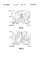
- FIGS. 1a to 1dshow the spectra of the laser output for various dither frequencies: FIG. 1a is a plot for a 10 MHz dither; FIG. 1b is a plot for a 100 MHz dither; FIG. 1c is a plot for a 990 MHz dither; and FIG. 1d is a plot for a 2 GHz dither;
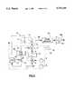
- FIG. 2illustrates a block diagram of the transmitter according to this invention
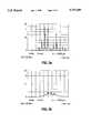
- FIG. 3ashows the spectrum of the laser optical output obtained experimentally with a dither according to prior art methods for SBS suppression
- FIG. 3bshows the spectrum of the laser optical output obtained experimentally according to this invention.
- the horizontal scaleis 1 GHz/div. in FIGS. 1a to 1c, the vertical scale is 20 nw/div. in FIGS. 1a and 1b and 50 nw/div. in FIG. 1c.
- FIG. 1dillustrates the spectrum for a 2 GHz dither.
- a relatively low frequency dither of up to 100 MHzleads to a continuous distribution of the optical power--at least continuous relative to the 20 MHz SBS linewidth.
- low frequency dithercannot be used for AM-VSB format because of the residual low frequency intensity modulation that would be left on the light.
- FIG. 1dillustrates a Power-frequency characteristic for a 2 GHz dither for carrying a CATV signal over the fiber.
- the spectrumis discontinuous, presenting spikes of various amplitudes and gaps of 2 GHz between adjacent sidebands. Since the gaps are 100 times the width of the SBS linewidth, considerable improvement of the SBS suppression may be obtained if the power in the sidebands is redistributed into the gaps between the sidebands.
- the present inventionprovides a method of achieving low frequency modulation of the temperature of the diode laser active region, to generate a wavelength chirp without actually applying a low frequency current.
- the frequency that may provoke a thermal modulation of the active region of the semiconductor lasermay be about 20 kHz.
- laser diode transmittersincorporate a temperature control element which is used to maintain a constant laser temperature despite environmental temperature changes. While this could be used to alter the laser temperature, the package thermal time constants are typically between 0.1-1 seconds, which means that there will not be a usable response at 20 kHz. Therefore, the laser package's temperature control element cannot be readily used to modulate the laser temperature.
- an amplitude modulationis directly applied to the semiconductor laser.
- One possibilityis to have a separate electrical contact and current path close to the active region of the laser diode just to generate a thermal modulation of f T at the active region, without effectively applying a current of frequency f T through the active region. This method would require a considerable re-design, and result in a very specialized laser product.
- Another methodwhich is more practical, is to take advantage of the thermal properties of the laser itself, using a technique to generate the required thermal modulation for any generally available laser.
- FIG. 2illustrates a block diagram of the optical transmitter according to this invention.
- a coherent light source 10generally comprises a laser diode 1, a laser drive unit, and a temperature control unit.
- the laser drive unitis not illustrated in FIG. 2, as it is a conventional unit and does not directly intervene in the invention.
- a light transducer 2commonly called back facet monitor (BFM), is typically installed inside laser sources for monitoring the parameters of the light emitted by laser 1.
- Light emitted by light source 10is transmitted over optical fiber 20 and is modulated with the CATV signal in external modulator 40.
- the CATV signalis provided by generator 30.
- the post-modulation optical amplifier 50is used to amplify the signal before it is transmitted over the fiber cable 60 to subscribers.
- Laser 1is biased with a DC current which is modulated with a dither signal 3 generated in dither generator 70.
- a counterbalancing unit 80is provided for suppressing any residual low frequency component that may appear in the emitted laser light.
- the electrical power that is dissipated in the diode laser 1can be modeled to first order by the following expression:
- Iis the applied current
- Vis the junction voltage of the laser diode considered to be clamped when biased above threshold, at a typical value of 0.8 volts;
- Ris the series resistance of the laser diode which is typically 5 ohms.
- the first two terms aboverepresent the power that is added to the active region by electrical dissipation (Joule heating).
- the last termrepresents the removal of power from the active region by the emitted light.
- the second term of the equationis not linearly dependent on the current, but rather depends upon the square of the current.
- This non-linearitymeans that if a signal with a pure f C frequency is applied, there will also be an associated response at the second harmonic and at DC.
- the nonlinear behavior of the second termbecomes more useful if the applied dither waveform is not a pure sine wave of frequency f C , but instead is centered around f C and has at least two spectral components that are separated by a low frequency, f T .
- the non-linearitywill generate sum and difference components in the power dissipation. The difference component will then be at f T in the power dissipation, leading to a component of frequency f T in the thermal modulation.
- the dither signal 3 output by generator 70is obtained by mixing a dither carrier (f C ) with a low frequency (f T ) signal.
- the mixer outputdoes not have an f T component and therefore there is no direct generation of the F T component on the optical output of the laser. Rather, as indicated above, a difference signal of frequency f T is generated from these sideband components by the nonlinearity of the laser "I-V" characteristic.
- the difference signal f Twill thermally modulate the laser to reshape the laser spectrum to a relatively continuous spectrum.
- a high pass filter 17may be used which will suppress low frequency components in the amplitude modulated current signal 8.
- the amplitude modulated signal 8is then corrected with a variable magnitude error signal 9 for suppressing any components having the frequency f T that may appear in the emitted laser light.
- the variable magnitude error signal 9is applied to a summation block 11, together with amplitude modulated signal 8, to form dither signal 3 which is applied over the control current of the laser 1.
- the dither carrier frequency f Cis selected to be at least twice the frequency band of the information signal.
- f C⁇ 2 GHz.
- the frequency of the modulating signalis selected to give a difference signal f T in a range between 10 to 20 kHz.
- thermal down-mixinghas led to a thermal modulation without ever modulating the current with frequency f T and its unacceptable intensity modulation.
- the thermal modulationalters the laser linewidth enough to provide substantial SBS suppression.
- a dither waveformwhich is centered at f C but which has components separated by f T .
- AMamplitude modulated
- the second term in Equation (1)will generate a 20 kHz thermal component, similar to the envelope detection process used in AM radios.
- Another method of generating spectral components which are separated by f Tis to strongly AM modulate a carrier f C with a signal having a frequency f T .
- the signalmay be a sine wave, a triangle or a square wave. If f C is 2 GHz, and f T is 20 kHz, this will also result in a 20 kHz envelope on the 2 GHz carrier, which will ultimately lead to a 20 kHz thermal contribution.
- DSBSCDouble Sideband Suppressed Carrier Modulation
- the particular hardware used for the dither generator 70is not limited to the embodiment illustrated and disclosed herein, but it is at the discretion of any person skilled in the art. It is important that a first signal generated with unit 70 for modulating the laser current has a frequency f C which is higher than twice the band of the information signal. It is also important that a second signal having a frequency which alone, or combined with the frequency of the first signal, gives a low frequency component which effects thermal modulation of the laser at a low frequency determined by the difference between the two signals.
- Counterbalance unit 80is provided for neutralizing this residual component from the output signal.
- the light emitted by laser diode 1is detected with light transducer 2, and a sample signal 12 is diverted from the light source.
- Sample signal 12will include any eventual residual optical fluctuations of frequency f T .
- a variable magnitude cancellation signal 9 at frequency f Tis applied to the summation block 11 with a phase opposite to the phase of the detected 20 kHz component, to cancel out the residual intensity fluctuations in a closed loop manner.
- This sampling of the emitted lightis most conveniently done using the signal from the BFM photodiode 2 which is typically installed inside laser packages, but could also be done by sampling a fraction of the front facet light going to the external modulator.
- the amplitude of the cancellation signal 9is applied in a closed loop manner, and thereby tracks out any variations due to slight changes in the thermal down-mixing.
- the analysis of the sampling signal 12is done with a phase sensitive detector (PSD) 13, which receives the sample signal and the modulating signal.
- a DC signal 14 proportional to the residual BFM component at f Tis generated at the output of the PSD 13.
- This signalis used to control the amplitude of the output of generator 6 which is added as variable amplitude cancellation signal 9 to the modulated dither signal 8 in summation block 11.
- the amplitude of the attenuated output of generator 6is adjusted with block 15, which may be a potentiometer.
- Phase adjust block 16provides the correct phase for the cancellation signal 9. In this way, the amplitude and the phase of the error signal 9 may be adjusted to substantially compensate for the residual component in the output signal.
- FIGS. 3a and 3bshow two experimental optical spectrum analyzer outputs of one implementation with a trial 750 MHz dither carrier current applied to the laser.
- the vertical scaleis identical between the two plots.
- FIG. 3ashows the spectrum of the output signal with the AM off. Several skinny sideband spikes separated by large gaps of 750 MHz are seen in this Figure.
- FIG. 3billustrates the spectrum of the output signal when a strong AM modulation is applied to the dither carrier of 750 MHz.
- the modulating signal for this experimentis a 10 kHz triangle wave at 81% modulation index. It is apparent that an important part of the power that was in the few strong sideband spikes has been redistributed in a continuous background due to the thermal down-mixing.
Landscapes
- Physics & Mathematics (AREA)
- Electromagnetism (AREA)
- Engineering & Computer Science (AREA)
- Computer Networks & Wireless Communication (AREA)
- Signal Processing (AREA)
- Optical Communication System (AREA)
- Semiconductor Lasers (AREA)
Abstract
Description
P.sub.diss =I*V+I.sup.2 R-aI Equation (1)
Claims (20)
Priority Applications (6)
| Application Number | Priority Date | Filing Date | Title |
|---|---|---|---|
| US08/587,046US5737109A (en) | 1996-01-16 | 1996-01-16 | Thermal down-mixing in diode laser transmitters to suppress stimulated brillouin scattering |
| EP96939793AEP0876716B1 (en) | 1996-01-16 | 1996-12-06 | Thermal down-mixing in diode laser transmitters to suppress stimulated brillouin scattering |
| PCT/CA1996/000818WO1997026723A1 (en) | 1996-01-16 | 1996-12-06 | Thermal down-mixing in diode laser transmitters to suppress stimulated brillouin scattering |
| DE69611799TDE69611799T2 (en) | 1996-01-16 | 1996-12-06 | THERMAL DOWN-MIXING IN LASER DIODE TRANSMITTERS FOR SUPPRESSING STIMULATED BRILLOUIN SCATTERING |
| CA002236115ACA2236115C (en) | 1996-01-16 | 1996-12-06 | Thermal down-mixing in diode laser transmitters to suppress stimulated brillouin scattering |
| JP9525544AJPH11502996A (en) | 1996-01-16 | 1996-12-06 | Thermal downmixing in a diode laser transmitter to suppress stimulated Brillouin scattering |
Applications Claiming Priority (1)
| Application Number | Priority Date | Filing Date | Title |
|---|---|---|---|
| US08/587,046US5737109A (en) | 1996-01-16 | 1996-01-16 | Thermal down-mixing in diode laser transmitters to suppress stimulated brillouin scattering |
Publications (1)
| Publication Number | Publication Date |
|---|---|
| US5737109Atrue US5737109A (en) | 1998-04-07 |
Family
ID=24348112
Family Applications (1)
| Application Number | Title | Priority Date | Filing Date |
|---|---|---|---|
| US08/587,046Expired - LifetimeUS5737109A (en) | 1996-01-16 | 1996-01-16 | Thermal down-mixing in diode laser transmitters to suppress stimulated brillouin scattering |
Country Status (6)
| Country | Link |
|---|---|
| US (1) | US5737109A (en) |
| EP (1) | EP0876716B1 (en) |
| JP (1) | JPH11502996A (en) |
| CA (1) | CA2236115C (en) |
| DE (1) | DE69611799T2 (en) |
| WO (1) | WO1997026723A1 (en) |
Cited By (25)
| Publication number | Priority date | Publication date | Assignee | Title |
|---|---|---|---|---|
| US6151145A (en)* | 1997-02-13 | 2000-11-21 | Lucent Technologies Inc. | Two-wavelength WDM Analog CATV transmission with low crosstalk |
| WO2000072451A3 (en)* | 1999-05-20 | 2001-03-01 | Ortel Corp | Apparatus and method for reducing impairments from nonlinear fiber effects in 1550 nanometer external modulation links |
| US6252692B1 (en)* | 1996-06-07 | 2001-06-26 | Nortel Networks Limited | Optical fibre transmission systems |
| US20010036206A1 (en)* | 1999-09-20 | 2001-11-01 | Jerman John H. | Tunable laser with microactuator |
| US6434173B1 (en) | 1998-09-11 | 2002-08-13 | New Focus, Inc. | Open loop wavelength control system for a tunable laser |
| US20020172239A1 (en)* | 1999-07-27 | 2002-11-21 | Mcdonald Mark E. | Tunable external cavity laser |
| US20030007522A1 (en)* | 2001-07-06 | 2003-01-09 | Hua Li | External cavity laser with orthogonal tuning of laser wavelength and cavity optical path length |
| WO2002011322A3 (en)* | 2000-07-28 | 2003-01-23 | Adc Telecommunications Inc | Suppression of stimulated brillouin scattering in optical transmissions |
| US20030016707A1 (en)* | 2000-07-27 | 2003-01-23 | Mcdonald Mark | Wavelength reference apparatus and method |
| US20030072869A1 (en)* | 2001-10-12 | 2003-04-17 | International Business Machines Corporation | Real-time process control for optical component fabrication |
| US6553043B1 (en)* | 1998-03-02 | 2003-04-22 | Jds Uniphase Corporation | Overcoming L-I kink effects in a laser diode feedback control |
| US6658031B2 (en) | 2001-07-06 | 2003-12-02 | Intel Corporation | Laser apparatus with active thermal tuning of external cavity |
| US6661815B1 (en)* | 2002-12-31 | 2003-12-09 | Intel Corporation | Servo technique for concurrent wavelength locking and stimulated brillouin scattering suppression |
| US20040001520A1 (en)* | 2001-12-12 | 2004-01-01 | General Instrument Corporation | Return path transmitter having a closed laser control loop that is employed in a hybrid fiber / coax transmission system |
| US6724797B2 (en) | 2001-07-06 | 2004-04-20 | Intel Corporation | External cavity laser with selective thermal control |
| US6804278B2 (en) | 2001-07-06 | 2004-10-12 | Intel Corporation | Evaluation and adjustment of laser losses according to voltage across gain medium |
| US6822979B2 (en) | 2001-07-06 | 2004-11-23 | Intel Corporation | External cavity laser with continuous tuning of grid generator |
| US6856632B1 (en) | 1999-09-20 | 2005-02-15 | Iolon, Inc. | Widely tunable laser |
| US6879619B1 (en) | 1999-07-27 | 2005-04-12 | Intel Corporation | Method and apparatus for filtering an optical beam |
| US7209498B1 (en)* | 2000-05-04 | 2007-04-24 | Intel Corporation | Method and apparatus for tuning a laser |
| US7230959B2 (en) | 2002-02-22 | 2007-06-12 | Intel Corporation | Tunable laser with magnetically coupled filter |
| US20080175278A1 (en)* | 2007-01-23 | 2008-07-24 | Peter Dragic | Narrow linewidth injection seeded Q-switched fiber ring laser based on a low-SBS fiber |
| US20090324256A1 (en)* | 2008-06-27 | 2009-12-31 | Fujitsu Limited | Optical transmitter |
| US20110081151A1 (en)* | 2009-09-30 | 2011-04-07 | Nec Laboratories America, Inc. | Generation and Coherent Detection of High-Speed Orthogonal DWDM Optical Signal |
| US20110206076A1 (en)* | 2007-01-18 | 2011-08-25 | Pyrophotonics Lasers, Inc. | Seed source for high power optical fiber amplifier |
Families Citing this family (1)
| Publication number | Priority date | Publication date | Assignee | Title |
|---|---|---|---|---|
| US8340531B2 (en)* | 2009-12-18 | 2012-12-25 | General Instrument Corporation | Method and apparatus for improved SBS suppression in optical fiber communication systems |
Citations (7)
| Publication number | Priority date | Publication date | Assignee | Title |
|---|---|---|---|---|
| EP0581525A1 (en)* | 1992-07-31 | 1994-02-02 | AT&T Corp. | Suppression of brillouin scattering in lightwave transmission system |
| US5329396A (en)* | 1992-10-28 | 1994-07-12 | At&T Bell Laboratories | Reduction of stimulated brillouin scattering in a fiber optic transmission system |
| US5359450A (en)* | 1992-06-25 | 1994-10-25 | Synchronous Communications, Inc. | Optical transmission system |
| US5373385A (en)* | 1993-11-12 | 1994-12-13 | At&T Corp. | Method and apparatus for reduction of optical communication system impairments |
| US5473625A (en)* | 1994-09-26 | 1995-12-05 | At&T Corp. | Tunable distributed Bragg reflector laser for wavelength dithering |
| US5477368A (en)* | 1994-12-29 | 1995-12-19 | At&T Corp. | High power lightwave transmitter using highly saturated amplifier for residual AM suppression |
| US5550667A (en)* | 1992-08-22 | 1996-08-27 | Alcatel N.V. | Optical transmitter |
- 1996
- 1996-01-16USUS08/587,046patent/US5737109A/ennot_activeExpired - Lifetime
- 1996-12-06WOPCT/CA1996/000818patent/WO1997026723A1/enactiveIP Right Grant
- 1996-12-06DEDE69611799Tpatent/DE69611799T2/ennot_activeExpired - Fee Related
- 1996-12-06EPEP96939793Apatent/EP0876716B1/ennot_activeExpired - Lifetime
- 1996-12-06JPJP9525544Apatent/JPH11502996A/enactivePending
- 1996-12-06CACA002236115Apatent/CA2236115C/ennot_activeExpired - Fee Related
Patent Citations (7)
| Publication number | Priority date | Publication date | Assignee | Title |
|---|---|---|---|---|
| US5359450A (en)* | 1992-06-25 | 1994-10-25 | Synchronous Communications, Inc. | Optical transmission system |
| EP0581525A1 (en)* | 1992-07-31 | 1994-02-02 | AT&T Corp. | Suppression of brillouin scattering in lightwave transmission system |
| US5550667A (en)* | 1992-08-22 | 1996-08-27 | Alcatel N.V. | Optical transmitter |
| US5329396A (en)* | 1992-10-28 | 1994-07-12 | At&T Bell Laboratories | Reduction of stimulated brillouin scattering in a fiber optic transmission system |
| US5373385A (en)* | 1993-11-12 | 1994-12-13 | At&T Corp. | Method and apparatus for reduction of optical communication system impairments |
| US5473625A (en)* | 1994-09-26 | 1995-12-05 | At&T Corp. | Tunable distributed Bragg reflector laser for wavelength dithering |
| US5477368A (en)* | 1994-12-29 | 1995-12-19 | At&T Corp. | High power lightwave transmitter using highly saturated amplifier for residual AM suppression |
Non-Patent Citations (8)
| Title |
|---|
| "Harmonic Distortion Caused by Stimulated Brillouin Scattering Suppression in Externally Modulated Lightwave AM-CATV Systems", F.W. Willems et al., Electronics Letters, vol. 30, #4, Feb. 17, 1994, pp. 343-345. |
| "Limitations on Lightwave Communications Imposed by Optical-Fiber Nonlinearities", A.R. Chraplyvy, Journal of Lightwave Technology, vol. 8, #10, Oct.90, pp. 1548-1557. |
| "Optimum Range for DFB Laser Chirp for Fiber-Optic AM Video Transmission", H.A. Blauvelt et al., Journal of Lightwave Technology, vol. 11, #1, Jan.93, pp. 55-59. |
| "Suppression of Brillouin Scattering in Lightwave AM-VSB CATV Transmission Systems", S.P. Mao et al., Conference on Optical Fiber Communications (OFC), Paper W18, 1993. |
| Harmonic Distortion Caused by Stimulated Brillouin Scattering Suppression in Externally Modulated Lightwave AM CATV Systems , F.W. Willems et al., Electronics Letters, vol. 30, 4, Feb. 17, 1994, pp. 343 345.* |
| Limitations on Lightwave Communications Imposed by Optical Fiber Nonlinearities , A.R. Chraplyvy, Journal of Lightwave Technology, vol. 8, 10, Oct.90, pp. 1548 1557.* |
| Optimum Range for DFB Laser Chirp for Fiber Optic AM Video Transmission , H.A. Blauvelt et al., Journal of Lightwave Technology, vol. 11, 1, Jan.93, pp. 55 59.* |
| Suppression of Brillouin Scattering in Lightwave AM VSB CATV Transmission Systems , S.P. Mao et al., Conference on Optical Fiber Communications (OFC), Paper W18, 1993.* |
Cited By (45)
| Publication number | Priority date | Publication date | Assignee | Title |
|---|---|---|---|---|
| US6252692B1 (en)* | 1996-06-07 | 2001-06-26 | Nortel Networks Limited | Optical fibre transmission systems |
| US6151145A (en)* | 1997-02-13 | 2000-11-21 | Lucent Technologies Inc. | Two-wavelength WDM Analog CATV transmission with low crosstalk |
| US6553043B1 (en)* | 1998-03-02 | 2003-04-22 | Jds Uniphase Corporation | Overcoming L-I kink effects in a laser diode feedback control |
| US6434173B1 (en) | 1998-09-11 | 2002-08-13 | New Focus, Inc. | Open loop wavelength control system for a tunable laser |
| US6493365B1 (en) | 1998-09-11 | 2002-12-10 | New Focus, Inc. | Passive thermal stabilization of the optical path length in a tunable laser |
| US6614829B1 (en) | 1998-09-11 | 2003-09-02 | New Focus, Inc. | Mechanically grounded tunable laser |
| WO2000072451A3 (en)* | 1999-05-20 | 2001-03-01 | Ortel Corp | Apparatus and method for reducing impairments from nonlinear fiber effects in 1550 nanometer external modulation links |
| US6252693B1 (en)* | 1999-05-20 | 2001-06-26 | Ortel Corporation | Apparatus and method for reducing impairments from nonlinear fiber effects in 1550 nanometer external modulation links |
| US6879619B1 (en) | 1999-07-27 | 2005-04-12 | Intel Corporation | Method and apparatus for filtering an optical beam |
| US20020172239A1 (en)* | 1999-07-27 | 2002-11-21 | Mcdonald Mark E. | Tunable external cavity laser |
| US6888856B2 (en) | 1999-07-27 | 2005-05-03 | Intel Corporation | Method and apparatus for filtering an optical beam |
| US6853654B2 (en) | 1999-07-27 | 2005-02-08 | Intel Corporation | Tunable external cavity laser |
| US20010036206A1 (en)* | 1999-09-20 | 2001-11-01 | Jerman John H. | Tunable laser with microactuator |
| US20080259972A1 (en)* | 1999-09-20 | 2008-10-23 | Iolon, Inc. | Widely tunable laser |
| US6856632B1 (en) | 1999-09-20 | 2005-02-15 | Iolon, Inc. | Widely tunable laser |
| US6847661B2 (en) | 1999-09-20 | 2005-01-25 | Iolon, Inc. | Tunable laser with microactuator |
| US7443891B1 (en) | 1999-09-20 | 2008-10-28 | Coherent, Inc. | Widely tunable laser |
| US7209498B1 (en)* | 2000-05-04 | 2007-04-24 | Intel Corporation | Method and apparatus for tuning a laser |
| US20030016707A1 (en)* | 2000-07-27 | 2003-01-23 | Mcdonald Mark | Wavelength reference apparatus and method |
| US7120176B2 (en) | 2000-07-27 | 2006-10-10 | Intel Corporation | Wavelength reference apparatus and method |
| WO2002011322A3 (en)* | 2000-07-28 | 2003-01-23 | Adc Telecommunications Inc | Suppression of stimulated brillouin scattering in optical transmissions |
| US6813448B1 (en) | 2000-07-28 | 2004-11-02 | Adc Telecommunications, Inc. | Suppression of stimulated brillouin scattering in optical transmissions |
| US7042917B2 (en) | 2001-07-06 | 2006-05-09 | Intel Corporation | Laser apparatus with active thermal tuning of external cavity |
| US6658031B2 (en) | 2001-07-06 | 2003-12-02 | Intel Corporation | Laser apparatus with active thermal tuning of external cavity |
| US6804278B2 (en) | 2001-07-06 | 2004-10-12 | Intel Corporation | Evaluation and adjustment of laser losses according to voltage across gain medium |
| US6724797B2 (en) | 2001-07-06 | 2004-04-20 | Intel Corporation | External cavity laser with selective thermal control |
| US6704332B2 (en) | 2001-07-06 | 2004-03-09 | Intel Corporation | Tunable external cavity laser |
| US20050078717A1 (en)* | 2001-07-06 | 2005-04-14 | Intel Corporation | Laser apparatus with active thermal tuning of external cavity |
| US20030007522A1 (en)* | 2001-07-06 | 2003-01-09 | Hua Li | External cavity laser with orthogonal tuning of laser wavelength and cavity optical path length |
| US6901088B2 (en) | 2001-07-06 | 2005-05-31 | Intel Corporation | External cavity laser apparatus with orthogonal tuning of laser wavelength and cavity optical pathlength |
| US20050135439A1 (en)* | 2001-07-06 | 2005-06-23 | Chapman William B. | External cavity laser method and apparatus with orthogonal tuning of laser wavelength and cavity optical path length |
| US6822979B2 (en) | 2001-07-06 | 2004-11-23 | Intel Corporation | External cavity laser with continuous tuning of grid generator |
| US7218652B2 (en) | 2001-07-06 | 2007-05-15 | Intel Corporation | External cavity laser method and apparatus with orthogonal tuning of laser wavelength and cavity optical path length |
| US6911090B2 (en)* | 2001-10-12 | 2005-06-28 | International Business Machines Corporation | Real-time process control for optical component fabrication |
| US20030072869A1 (en)* | 2001-10-12 | 2003-04-17 | International Business Machines Corporation | Real-time process control for optical component fabrication |
| US20040001520A1 (en)* | 2001-12-12 | 2004-01-01 | General Instrument Corporation | Return path transmitter having a closed laser control loop that is employed in a hybrid fiber / coax transmission system |
| US6934310B2 (en) | 2001-12-12 | 2005-08-23 | General Instrument Corporation | Return path transmitter having a closed laser control loop that is employed in a hybrid fiber / coax transmission |
| WO2003050572A3 (en)* | 2001-12-12 | 2004-01-29 | Gen Instrument Corp | Return path transmitter having a closed laser control loop |
| US7230959B2 (en) | 2002-02-22 | 2007-06-12 | Intel Corporation | Tunable laser with magnetically coupled filter |
| US6661815B1 (en)* | 2002-12-31 | 2003-12-09 | Intel Corporation | Servo technique for concurrent wavelength locking and stimulated brillouin scattering suppression |
| US20110206076A1 (en)* | 2007-01-18 | 2011-08-25 | Pyrophotonics Lasers, Inc. | Seed source for high power optical fiber amplifier |
| US20080175278A1 (en)* | 2007-01-23 | 2008-07-24 | Peter Dragic | Narrow linewidth injection seeded Q-switched fiber ring laser based on a low-SBS fiber |
| US7577178B2 (en)* | 2007-01-23 | 2009-08-18 | Peter Dragic | Narrow linewidth injection seeded Q-switched fiber ring laser based on a low-SBS fiber |
| US20090324256A1 (en)* | 2008-06-27 | 2009-12-31 | Fujitsu Limited | Optical transmitter |
| US20110081151A1 (en)* | 2009-09-30 | 2011-04-07 | Nec Laboratories America, Inc. | Generation and Coherent Detection of High-Speed Orthogonal DWDM Optical Signal |
Also Published As
| Publication number | Publication date |
|---|---|
| EP0876716B1 (en) | 2001-02-14 |
| WO1997026723A1 (en) | 1997-07-24 |
| JPH11502996A (en) | 1999-03-09 |
| DE69611799D1 (en) | 2001-03-22 |
| CA2236115A1 (en) | 1997-07-24 |
| DE69611799T2 (en) | 2001-05-31 |
| CA2236115C (en) | 2001-08-14 |
| EP0876716A1 (en) | 1998-11-11 |
Similar Documents
| Publication | Publication Date | Title |
|---|---|---|
| US5737109A (en) | Thermal down-mixing in diode laser transmitters to suppress stimulated brillouin scattering | |
| US7349637B1 (en) | Optical transmitter with SBS suppression | |
| US6252693B1 (en) | Apparatus and method for reducing impairments from nonlinear fiber effects in 1550 nanometer external modulation links | |
| Willems et al. | Simultaneous suppression of stimulated Brillouin scattering and interferometric noise in externally modulated lightwave AM-SCM systems | |
| US6282003B1 (en) | Method and apparatus for optimizing SBS performance in an optical communication system using at least two phase modulation tones | |
| EP0595536B1 (en) | Reduction of stimulated brillouin scattering in a fiber optic transmission system | |
| Phillips et al. | Nonlinear distortion generated by dispersive transmission of chirped intensity-modulated signals | |
| US5828477A (en) | Multi-tone phase modulation for light wave communication system | |
| Smith et al. | Technique for optical SSB generation to overcome dispersion penalties in fibre-radio systems | |
| US5430569A (en) | Suppression of noise and distortion in fiber-optic systems | |
| US8340531B2 (en) | Method and apparatus for improved SBS suppression in optical fiber communication systems | |
| US6535315B1 (en) | Optical fiber transmitter for simultaneously suppressing stimulated brillouin scattering and self/external-phase modulation-induced nolinear distortions in a long-distance broadband distribution system | |
| US7031050B2 (en) | Method and system for precision cross-talk cancellation in optical amplifiers | |
| JP3405046B2 (en) | Laser light generator | |
| EP0653854A1 (en) | Method and apparatus for reduction of optical communication system impairments | |
| US7127182B2 (en) | Efficient optical transmission system | |
| JPH07114305B2 (en) | Interferometer device for reducing harmonic distortion in laser communication systems | |
| US5617239A (en) | Optical source for communications system | |
| GB2359684A (en) | Reduction of stimulated Brillouin backscattering (SBS) in optical transmission systems | |
| Junker et al. | High quality millimeter wave generation via stimulated Brillouin scattering | |
| JP3388956B2 (en) | Optical transmission equipment | |
| Trisno et al. | Video multicast using a VSB-AM external modulator at 1.5 mu m | |
| Chen | Enhanced analog transmission over fiber using sampled amplitude modulation |
Legal Events
| Date | Code | Title | Description |
|---|---|---|---|
| AS | Assignment | Owner name:NORTHERN TELECOM LIMITED, CANADA Free format text:ASSIGNMENT OF ASSIGNORS INTEREST;ASSIGNOR:BELL-NORTHERN RESEARCH LTD.;REEL/FRAME:007933/0173 Effective date:19960429 Owner name:BELL-NORTHERN RESEARCH LTD., CANADA Free format text:ASSIGNMENT OF ASSIGNORS INTEREST;ASSIGNOR:GOODWIN JOHN CHARLES;REEL/FRAME:007937/0583 Effective date:19960104 | |
| STCF | Information on status: patent grant | Free format text:PATENTED CASE | |
| AS | Assignment | Owner name:NORTEL NETWORKS CORPORATION, CANADA Free format text:CHANGE OF NAME;ASSIGNOR:NORTHERN TELECOM LIMITED;REEL/FRAME:010567/0001 Effective date:19990429 | |
| AS | Assignment | Owner name:NORTEL NETWORKS LIMITED, CANADA Free format text:CHANGE OF NAME;ASSIGNOR:NORTEL NETWORKS CORPORATION;REEL/FRAME:011195/0706 Effective date:20000830 Owner name:NORTEL NETWORKS LIMITED,CANADA Free format text:CHANGE OF NAME;ASSIGNOR:NORTEL NETWORKS CORPORATION;REEL/FRAME:011195/0706 Effective date:20000830 | |
| FPAY | Fee payment | Year of fee payment:4 | |
| FPAY | Fee payment | Year of fee payment:8 | |
| FPAY | Fee payment | Year of fee payment:12 | |
| AS | Assignment | Owner name:ROCKSTAR BIDCO, LP, NEW YORK Free format text:ASSIGNMENT OF ASSIGNORS INTEREST;ASSIGNOR:NORTEL NETWORKS LIMITED;REEL/FRAME:027164/0356 Effective date:20110729 | |
| AS | Assignment | Owner name:ROCKSTAR CONSORTIUM US LP, TEXAS Free format text:ASSIGNMENT OF ASSIGNORS INTEREST;ASSIGNOR:ROCKSTAR BIDCO, LP;REEL/FRAME:032388/0467 Effective date:20120509 | |
| AS | Assignment | Owner name:RPX CLEARINGHOUSE LLC, CALIFORNIA Free format text:ASSIGNMENT OF ASSIGNORS INTEREST;ASSIGNORS:ROCKSTAR CONSORTIUM US LP;ROCKSTAR CONSORTIUM LLC;BOCKSTAR TECHNOLOGIES LLC;AND OTHERS;REEL/FRAME:034924/0779 Effective date:20150128 |